

Page 1

THE POWER OF PERFORMANCE
RADIO CONTROLS
C4
Service Manual
Rev. 2
07-2008
GB
Page 2

Radio controls
THE POWER OF PERFORMANCE
2
Page 3
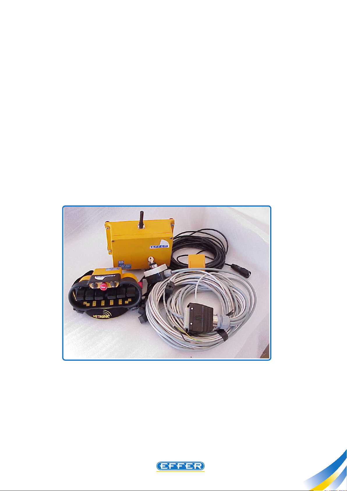
Radio controls HETRONIC BMS1
THE POWER OF PERFORMANCE
HETRONIC
Radio control BMS 1
GA610 BMS NOVA - 6L
C4.1
Features: Working Range approx. 100 m
Operating temperature -20° ÷ +70° C
Transmission speed 4800 Baud
Watertight Degree IP 65
836
3
Page 4

Radio controls HETRONIC BMS1
THE POWER OF PERFORMANCE
4
C4.1
Radio controls HETRONIC BMS1
Page 5
Radio controls HETRONIC BMS1
THE POWER OF PERFORMANCE
C4.1
1 - Operation
u The radio remote controls tted on the EFFER cranes consist with a transmitter, (also called key-board), of very
reduced size and weight, supplied with adjustable support and carrying belt to help the operator in his/her work,
and with a receiver applied on the crane, connected electrically to the controlbank.
u The electric signals sent to the receiver by the operator whenever he/she moves the transmitter paddles, are
transformed by the receiver itself into small shifts of the levers of the crane controlbank.
u Many crane movements may occur simultaneously. Moreover, as the movements are proportional, small shifts
of the transmitter paddles performed by the operator correspond to low speed crane movements, whereas the
higher is the shift of the joystick, the higher is the crane operating speed.
u The dialogue between the transmitter and the receiver occurs thru a preset radio frequency. In order to avoid
possible interferences with other radio control units, which might cause an accidental operation of the crane,
the radio remote control is equipped with an electronic device. That device will send the received signal to the
controlbank only after having checked that it really came from the combined transmitter.
NOTE: Read in whole the following sections before trying any modication or repair to the radio remote
controls. You might nd these modications unnecessary once you know how the whole system works and
how the settings are carried out!
1930744
5
Page 6

Radio controls HETRONIC BMS1
THE POWER OF PERFORMANCE
6
C4.1
Radio controls HETRONIC BMS1
2 - Radio remote control,
u This radio remote control is specially appreciated for the reduced size of its receiver unit (160 x 210, depth: 90
mm). It is available with either 12 V. DC or 24 V. DC.
u In case of 24 V. DC power supply, when six functions are selected simultaneously, the max. absorption is 3.8
Ampere.
u The safety fuse located in the receiver, is sized to max. 7.5 A.
u The transmitter features the typical “Binoculars” shape of Hetronic.
u The standard supply includes:
1 Receiver unit see section 2.1
2 Transmitter unit see section 2.2
3 Battery charger with spare battery see section 2.3
4 Emergency cable, length: 20 mt. see section 2.4
5 Programming red key see section 2.5
type“GA610 BMS NOVA - 6 L”
2
1
4
5
029
3
Page 7
Radio controls HETRONIC BMS1
THE POWER OF PERFORMANCE
C4.1
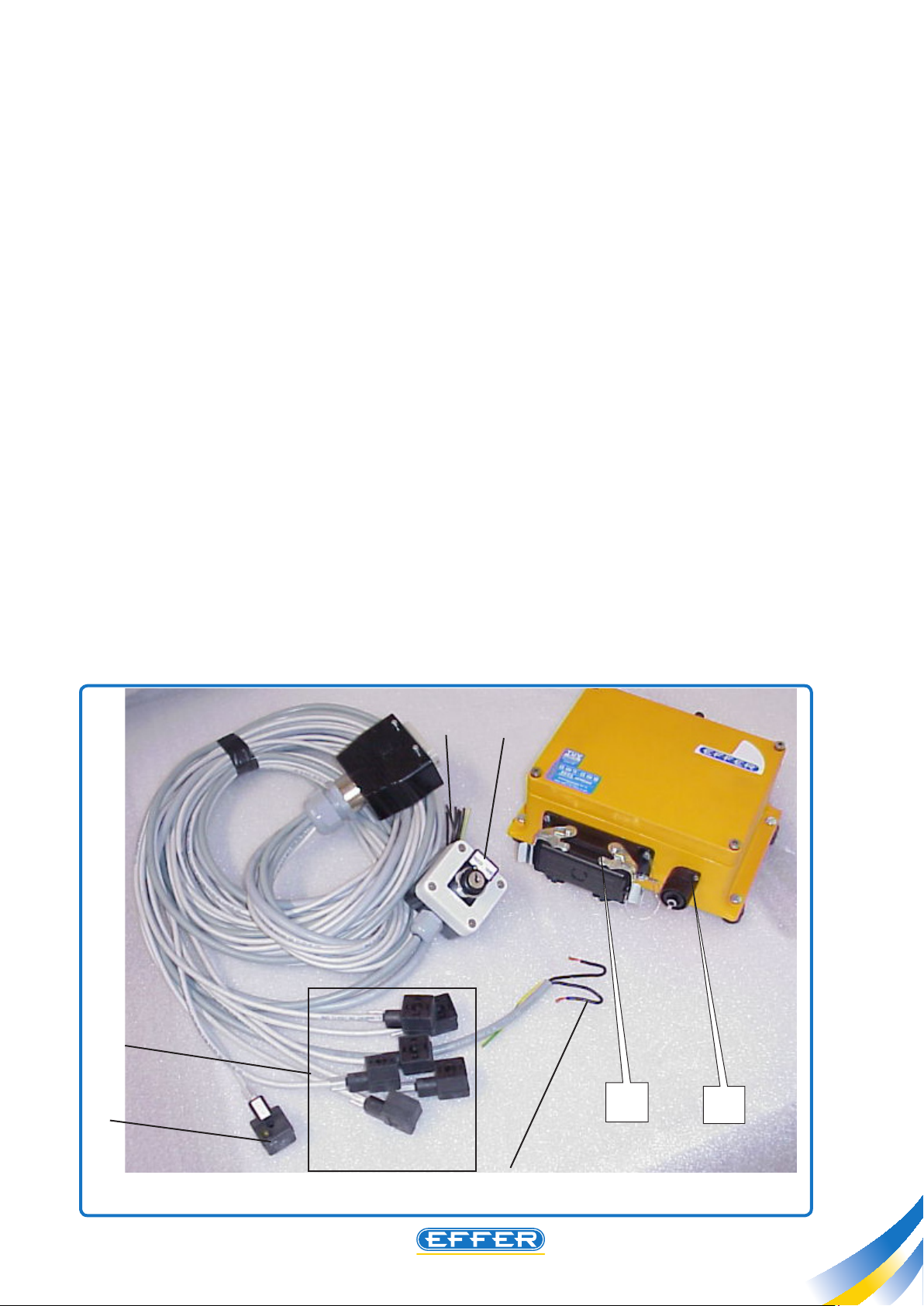
2.1 Receiver unit
The receiver unit features two electric connectors:
A- to connect the wires for the controlbank operation and for the power supply
B- to connect the emergency cable (see information on this cable in section 2.4)
THE CONNECTOR APPLIED ON THE POINT “A” HAS 32 PINS SOME OF THEM VOID FOR THE FOLLOWING
CONNECTIONS:
u Six equal electric connectors, to connect six proportional activators located on the crane hydraulic controlbank
(ref. M).
u Additional electric connector (ref. N), with a LED included, to supply the main oil relief valve on the
controlbank.
u Electric supply, connected to the cable (ref. O) with three pins (marked: 1-2-yellow / green). The negative polarity
shall be connected to the wire marked 1, whereas the positive polarity goes to the wire marked 2. The yellow/green
pin is not employed for the normal use of the radio control as it was designed for special accessories such as for
example aerial platforms, or warning signals indicating that the radio-controls are at use.
u The box (ref. P) with key for the selection of the type of crane operation (manual operation / radio remote
control operation) is connected to the same group of wires mentioned above and is applied to the point “A” on
the receiver.
u When selecting the manual operation, the connector ref. N is powered up continuously, whereas in radio remote
control operation, that connecter is powered up only when a transmitter paddle is activated.
u An additional cable (ref. Q) of 10-mm diameter, is applied to the same connector “A”; six black wires marked
from 1 to 6, and one yellow/green wire are gathered inside the cable. The output wires of the radio remote control,
marked from 1 to 5, are to be connected to the truck accessories: by selecting the corresponding controls on the
transmitter, these wires will convey an electric signal.
Q
P
M
N
O
A
B
030
7
Page 8
Radio controls HETRONIC BMS1
THE POWER OF PERFORMANCE
8
C4.1
Radio controls HETRONIC BMS1
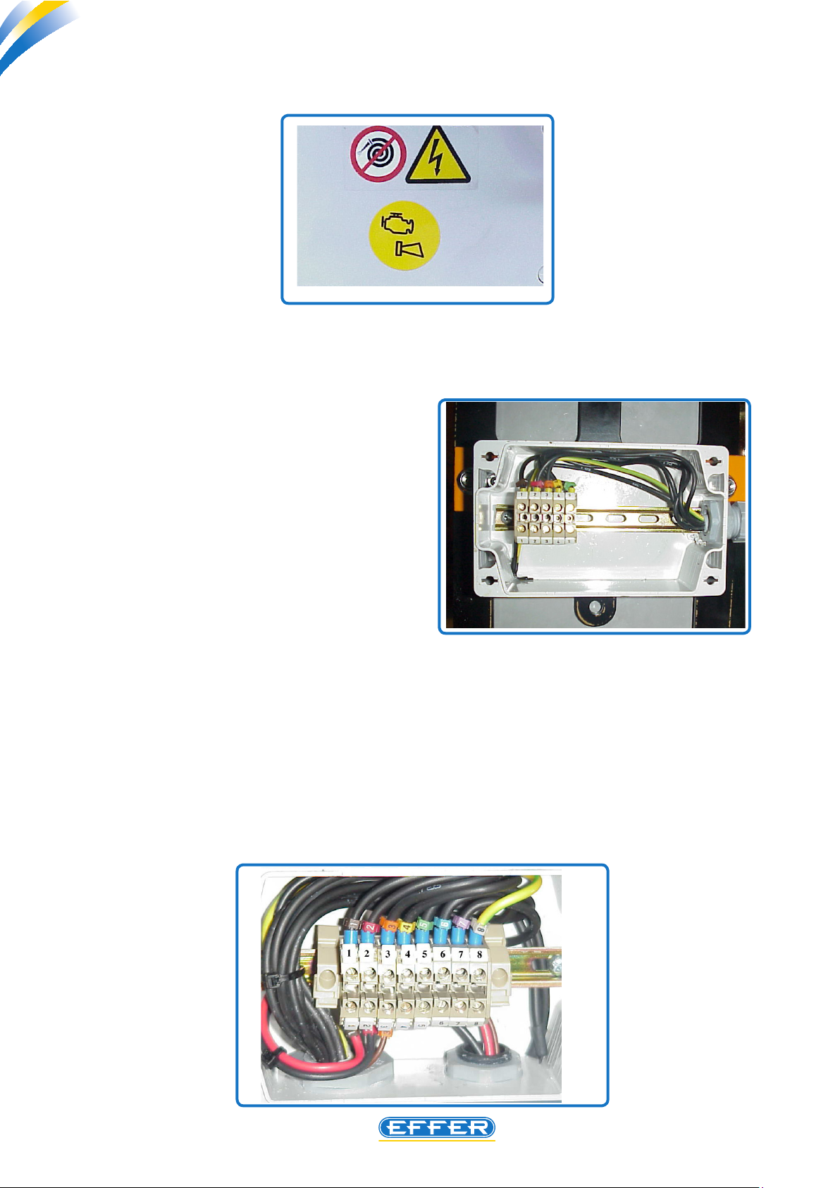
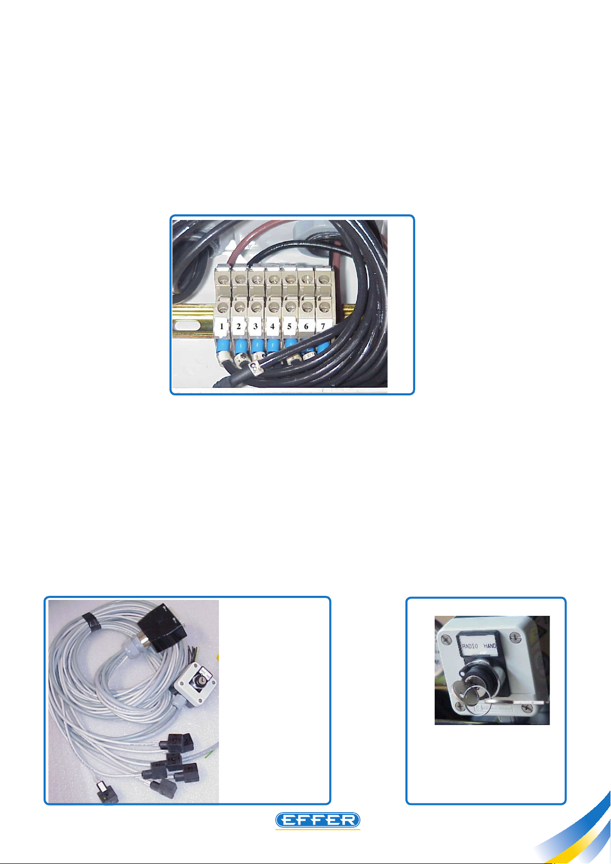
Box for electric accessory connection
272
1st example:
u Crane with bottom-side controlbank (mounted on the crane base). The a.m. connections are inside the electric
box (ref. W) mounted on the crane base. The terminal board bears the number/markings of the single wires.
Terminal 1: Signal for buzzer connection. When
connected, it operates if activated by the operator
(see transmitter unit instructions, section 2.2.8) or
while programming the radio control (see section
2.5/2.6).
Terminal 2: Signal for truck engine start
Terminal 3: Signal for truck engine stop
Terminal 4: Signal for truck engine RPM increase
Terminal 5: Sign al for truck engine RPM
decrease
Spare wire: Signal available for special accessories
(excluding PFI version cranes).
2nd example:
u Crane with controlbank on the column (mounted on the column side) - no operator’s seat, supplied or
not with the anti-tilting device, or with top-seat controls (but only when an anti-tilting device is tted to the crane
as well).
A terminal board is located inside the box (ref. T) applied on the crane base and the terminals for the connection
of the truck accessories are the following:
T
Page 9
Radio controls HETRONIC BMS1
THE POWER OF PERFORMANCE
Terminal 4: Signal for buzzer connection. When connected, it operates if activated by the operator (see transmitter
unit instructions, section 2.2.8) or while programming the radio control (see section 2.5/2.6 ).
Terminal 5: Signal for truck engine start
Terminal 6: Signal for truck engine stop
Terminal 7: Signal for truck engine RPM increase
Terminal 8: Signal for truck engine RPM decrease
C4.1
3rd example:
u Crane with top-seat controls, with operator’s seat but no anti-tilting device
Y
A terminal board is located inside the box (ref. Y) on the crane base and the terminals for the connection of the
truck accessories are the following:
Terminal 3: Signal for buzzer connection. When connected, it operates if activated by the operator (see transmitter
unit instructions, section 2.2.8) or while programming the radio control (see section 2.5/2.6).
Terminal 4: Signal for truck engine start
Terminal 5: Signal for truck engine stop
Terminal 6: Signal for truck engine RPM increase
Terminal 7: Signal for truck engine RPM decrease.
NOTE: These signals have been designed for relay activation. Their direct connection to claxson, solenoid valves
or to any device with absorption more than 0.5 Ampere is not possible.
The above mentioned signals have positive polarity.
EFFER Parts Numbers:
E FF E R p a r t #
899 123 5 - wi re
for the connection
“A ”, c o m p l e te
with conne cting
p lu g, b o x f or
cran e ope ration
selection, and cable
fo r ac cess or ies
connection.
EFFER part # 8990768
box ref. P with key switch.
9
Page 10
Radio controls HETRONIC BMS1
THE POWER OF PERFORMANCE
10
C4.1
Radio controls HETRONIC BMS1
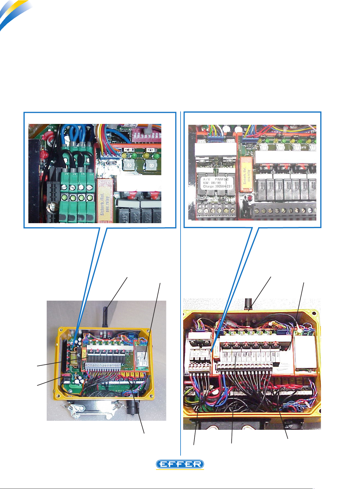
On the receiver unit the following parts can be identied :
1. Radio antenna (see section 2.1.1)
2. Fuse 7.5 A
3. Electronic module for the activation of the Hawe controlbank levers
4. Radio receiver Module
5. Electronic module transforming the signals from the transmitter into controls to the controlbank
6. Module for the activation of the 7
th
/ 8th function
OPTIONAL
1
4
900x
OPTIONAL
1
4
3
3
2
2
5
2
3
5
Page 11
Radio controls HETRONIC BMS1
THE POWER OF PERFORMANCE
C4.1
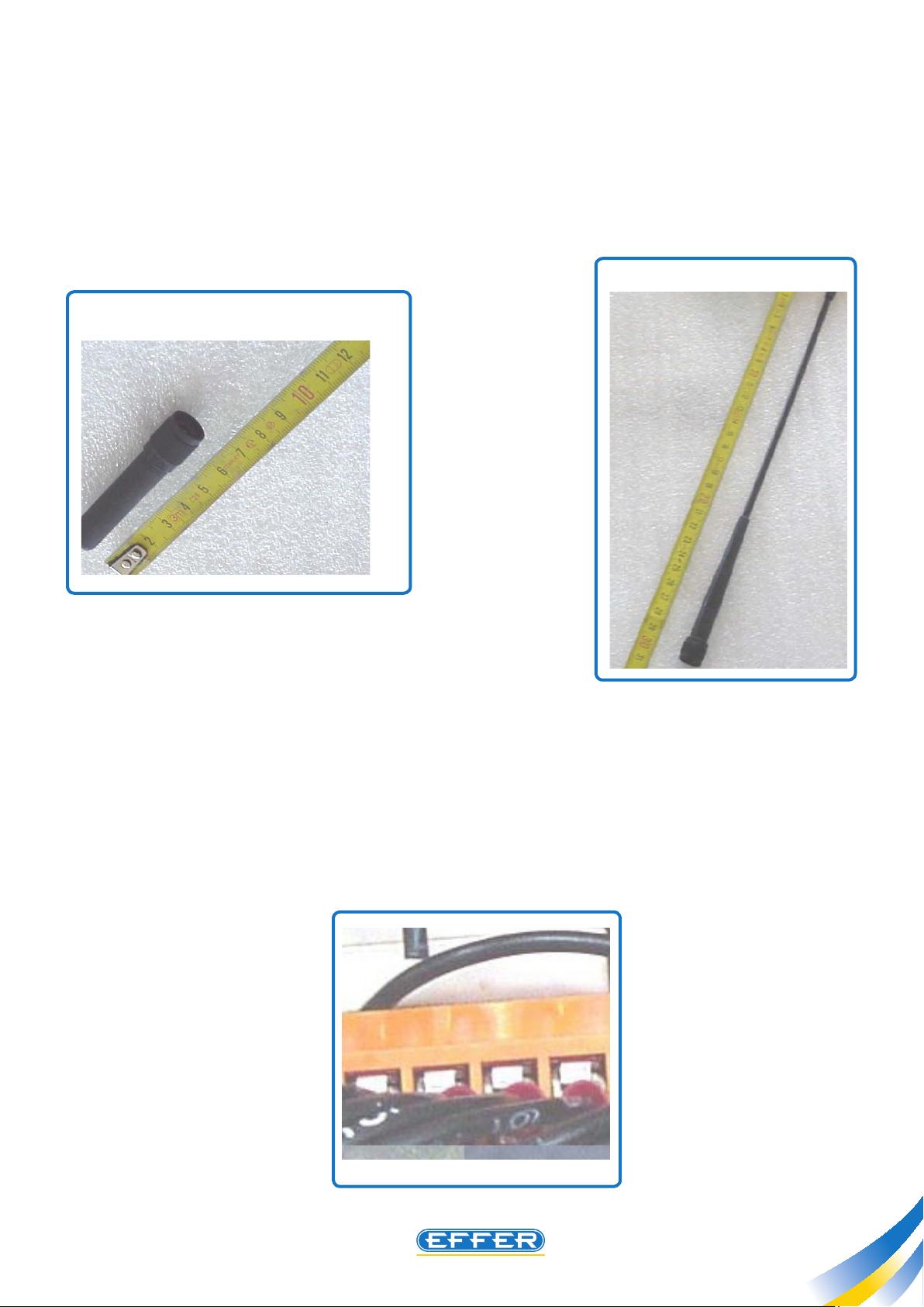
2.1.1 Radio remote control antenna, EFFER part # 8990710
u We recommend that you do not crash or bend it. In order to avoid damaging the thread, do not over-fasten
the lock ring nut.
The inner contact should be clean. As it is a gold-plated contact, no protective antioxidant treatment is required.
EFFER part # 8991442
EFFER part # 8990710
234L
231L
2.1.2 Fuse, EFFER part # 9394876
u This fuse is of a standard Automotive type, with bayonet joint.
Safety Standards for Fire Prevention command that a fuse is applied to the whole system. Do not exceed the
Amperage limit of 7.5 Ampere.
038
11
Page 12
Radio controls HETRONIC BMS1
THE POWER OF PERFORMANCE
12
C4.1
Radio controls HETRONIC BMS1
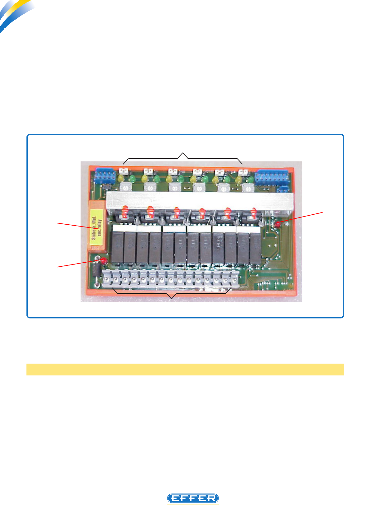
2.1.3 Electronic module for controlbank paddle operation, EFFER part # 8991236
for HAWE, EFFER part # 8991380 for DANFOSS
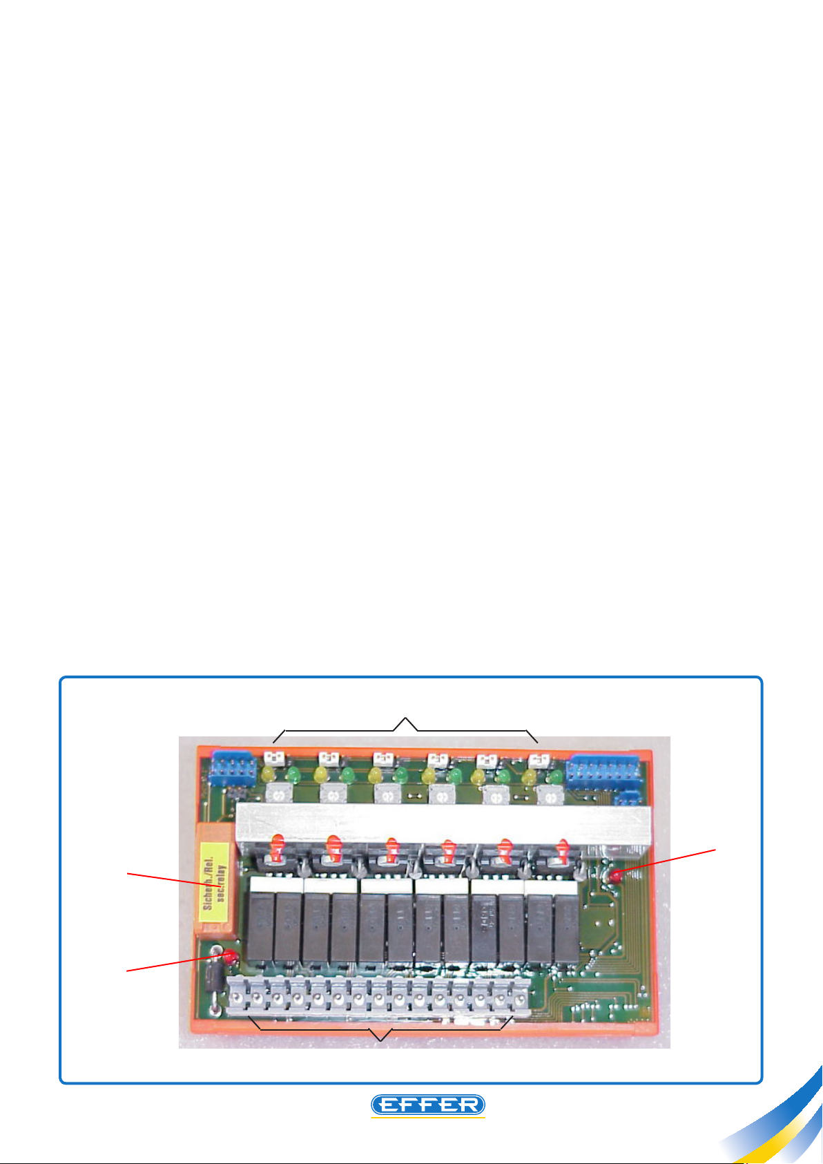
u A red LED (ref. Y) is located on the module bottom, on its left side. It lights up whenever any paddle of the
transmitter is moved, indicating that there is actually a power supply to the main solenoid valve tted on the
controlbank.
The signal output is on the terminal 3, marked YO.
of the main solenoid valve on the controlbank light up. If the LED does not light up, check the electric connection
or the correct operation of the relay (ref. Z).
The same signal makes also the LED tted on the connector
T
V
Z
Y
033
S
Six yellow LEDs and six green LEDs are located on the upper side of the electronic module (ref. T): they light up when
one of the paddle is moved. Starting from the left, you nd the LEDs connected to the paddles corresponding to
the following functions: crane slewing, rst (main) boom, second (knuckle) boom, extension, 1st supplementary
control, and 2nd supplementary control.
NOTE: When the crane is equipped with a winch, this is activated by the 2nd supplementary control.
u The yellow LEDs light up when a function is occurring, sending oil to the port B of the controlbank, while
the green LEDs light up when oil is sent to the port A of the controlbank (see also Service manual of the HAWE
controlbanks).
u Under the LEDs row, six small potentiometers control the feathering intensity of the controlbank lever. The
feathering of the lever is necessary to perform even very small movements, avoiding the interference of mechanic
frictions at the start-up stage.
u Note however, that HAWE levers shall not vibrate visibly (they’ll rather look steady while moving by radio); you’ll
just feel they slightly vibrate while touching the levers when radio-controlling the crane.
In general, we can state that adjusting the potentiometer at half stroke grants the best performance of the HAWE
controlbank.
Page 13
Radio controls HETRONIC BMS1
THE POWER OF PERFORMANCE
12 more electric connections (ref. S) are located on the lower side of the electronic module. These are connected
to the cables conveying the signals to the six functions of the crane controlbank. These connections are marked
by numbers 4 to 15 on the female connectors and bear the references marked A1, A2 etc. on the male connectors.
They are connected to the 12 LEDs ref. T , upwards, in the same position order.
The transmitted electric signal of these connections is dened as “under power”.
In order to verify the presence of this signal, use a tester for power check (or even a simple test lamp), providing
a connection at the point 2 (negative cable connection).
As a consequence of what has been explained above, when a transmitter paddle is activated, the red LED and the
LED corresponding to the selected manoeuvre will light up.
If many manoeuvres are performed simultaneously, many LEDs will light up on the upper side.
u On the right side of the board, an additional red LED is tted (ref. V). It lights up when a short-circuit occurs. If
it lights up while a specic manoeuvre is occurring, check the electric circuit corresponding to that manoeuvre,
included the activator tted to the corresponding lever on the crane controlbank.
On the upper side of the board, above the LEDs ref. T, six jumpers are tted.
u When jumpers are located between the central pin and the left pin, the radio remote control can operate
controlbanks equipped with 24-volt coils, while if the jumpers are located between the central pin and the right
pin, the radio remote control can operate controlbanks equipped with 12-volt coils.
C4.1
Z
Y
T
V
033
S
13
Page 14
Radio controls HETRONIC BMS1
THE POWER OF PERFORMANCE
14
C4.1
Radio controls HETRONIC BMS1
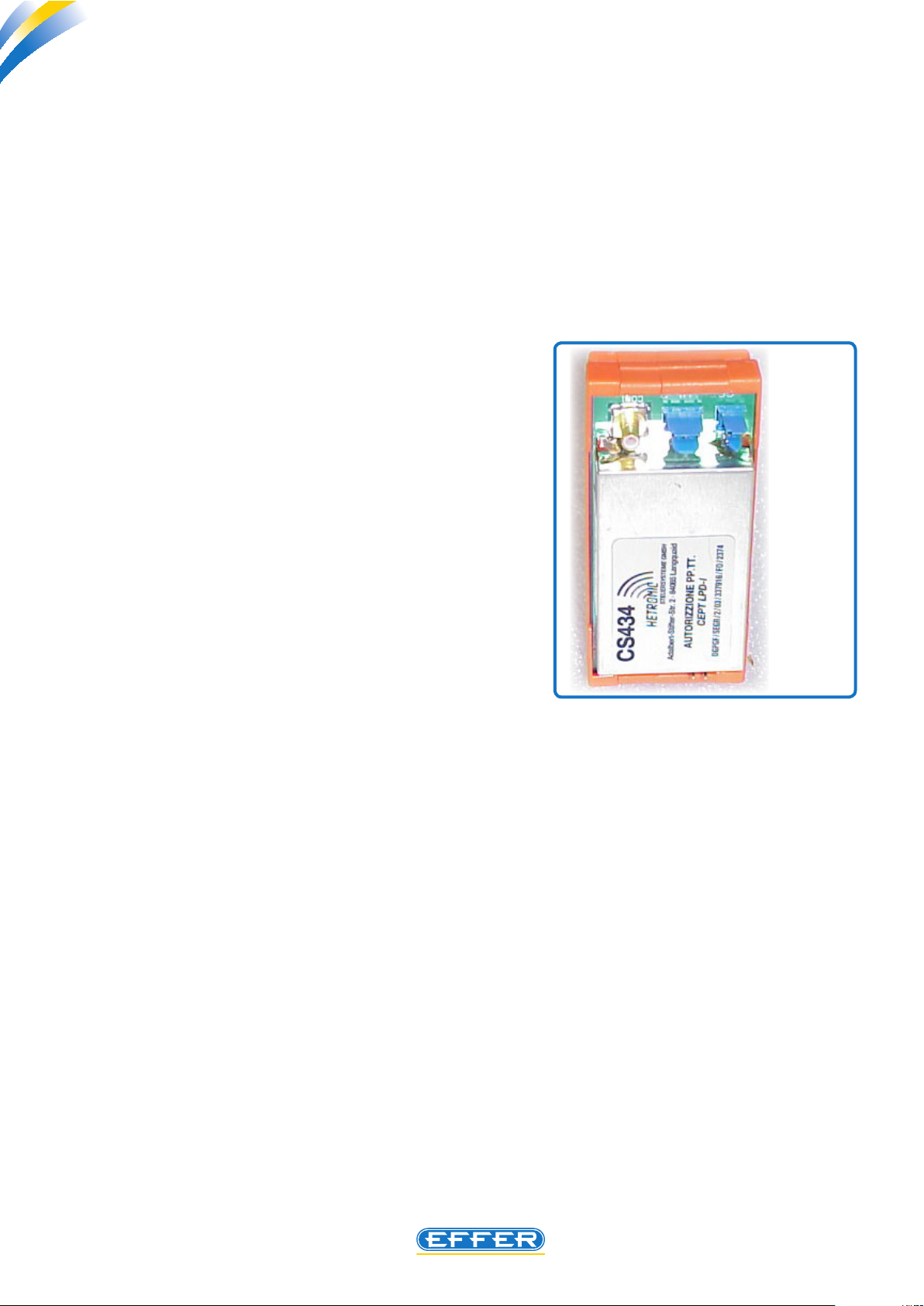
2.1.4 Receiver radio module:
EFFER part # 8991237 (European Frequency and other countries Ref. CS434)
EFFER part # 8991238 (American Frequency and other countries Ref. CS458)
NOTE: The two references above indicate the type of radio transmission frequency, according to the
homologation obtained by Hetronic in your country.
u Upon specic request, the EFFER Technical Department will give you the exact reference code according to
the country in which the radio remote control shall be used. This module receives the signals transmitted to the
radio antenna.
This module is excluded when you operate with the emergency cable (see section 4).
u In case of a fault occurred to the radio remote
control, where there is no physical damage to the
antenna, and the fault disappears when using the
emergency cable, the most probable cause has to be
investigated in the receiver radio module (or in the
transmitter module located inside the transmitter,
see section 2.2.13), or in a wire disconnected in the
electric circuit.
034
2.1.5 Electronic basic module, to turn the transmitter output signals into
controls to the controlbank
EFFER part # 8991239 until rst months 2001 (Fig. A),
EFFER part # 8991239A since rst months 2001 (Photo B, not shown)
This module is tted with twelve relays, each of them having a small red lamp on the upper side to show when
they are being activated electrically.
Those relays (ref. E) not only send the signals to the wires of the accessories (k2=buzzer; k3=truck engine rpm
increase; k4= truck engine rpm decrease; k8= truck engine start; k9= truck engine stop), but also control the
operation of the radio remote control or of the crane (k5 or K6 =enabling the 7th and 8th function; k10= for crane
equipped with the
On the upper side of the module of the radio remote controls delivered until the beginning of 2001, 16 switches
(ref. F) are located. They dene the dialogue Code between the transmitter unit and the receiver unit. 16 more
similar switches are tted in the transmitter unit to the same purpose.
That Code must never be changed, as no trouble can be solved by changing the dialogue Code. Electronic module
EFFER part # 8991239.
The radio remote controls delivered since the beginning of 2001 are equipped with a single part with xed code
“Ref. F” instead of the switches. Electronic module EFFER part # 8991239A.
Four LEDs visible from the outside too, are located on the upper side, on the right. They have the following
meaning:
Yellow: turning the key applied to the box ref. P (see section 2.1).
OperatiOn- It starts ashing after approximately 3 sec. since the radio remote control is powered up, by
FPI device only). The remaining relays are not used normally (k1, k7, k11, k12).
Page 15

Radio controls HETRONIC BMS1
THE POWER OF PERFORMANCE
Green: -Signal- It starts ashing when the transmitter is turned ON. It blinks faster when the emergency stop push-
button on the transmitter unit is pressed, or when the battery tted on the transmitter unit is exhausted.
errOr- It starts ashing when the transmitter unit is activated by a lever control paddle or with an accessory
Red: control switch left “on” from previous operations. (control for truck engine rpm increase/decrease, and -if suppliedcontrol for 7th and 8th function, see the last section of the description of the transmitter unit). It also ashes when
a manoeuvre for the activation of the dialogue between the transmitter unit and the receiver was carried out too
fast. Exit the error mode by repeating the complete starting procedure. Finally, it might also indicate there are
electric faults in the receiver unit.
C4.1
Yellow: when the green LED is OFF or ashes continuously.
nOrmal- When lit, it means the whole system works correctly. It lights o when the red LED lights up, or
F’
F’’
036
E
Fig. A
037
15
Page 16

Radio controls HETRONIC BMS1
THE POWER OF PERFORMANCE
16
C4.1
Radio controls HETRONIC BMS1
2.1.6 Module for the activation of the 7th /8th function
When the radio remote control is designed for the activation of the 7th or 8th lever of the hydraulic controlbank,
the transmitter is provided with a switch (see section 2.2.6) and inside the receiver, an electronic module, through
the shift of the 5th and 6th control lever paddle, controls the corresponding 8th and the 7th control lever movements.
When the controlbank seventh lever needs to be activated by the radio remote control, the tted module is connected to the 6th transmitter control lever only.
The fuse amperage does not change.
Module Ref. 6’
The mentioned module has 4 relays with
corresponding green LEDs that light up
when the shift is occurring.
Operating speeds of the 7th and the
8th lever are the same as the 6th and
the 5th lever.
6’
EFFER part # 8991240 for 12-volt version
EFFER part # 8991241 for 24-volt version
The radio remote controls delivered since
the beginning of 2001 are equipped with a
receiver with an electronic module Ref. 6”.
EFFER part # 8991322, valid for both 12
volt and 24 volt version
This electronic module controls dierent
operating speeds for the 5th and the 8th
lever, and for the 6th and the 7th lever.
900x
6’’
NOTE: A push-button for the system
Reset is tted inside the receiver unit
(Pos. R).
The use of this push-button should be
avoided, to prevent all the programmed
functions from being reset totally.
R
Page 17

Radio controls HETRONIC BMS1
THE POWER OF PERFORMANCE
C4.1
2.2 Transmitter unit
The transmitter unit is provided with the following functions:
2.2.1 A- Push-button for emergency stop – EFFER part #8991242 -. Press this push-button to turn o the radio
remote control, and to cut out the main solenoid valve applied to the controlbank inlet. As a consequence, all
crane movements will be stopped immediately. To go back to work, turn the push-button clockwise, as shown by
the arrows on the red knob.
2.2.2 B- Proportional paddles – EFFER part #8991130 -. These paddles, all alike, activate the hydraulic controlbank
levers, according to the paddle shift performed by the operator, providing proportional and progressive crane
movements.
2.2.3 C- Green LED – EFFER part #8991243 - It starts ashing when the radio remote control is turned ON. It ashes
faster to indicate that the transmitter battery is exhausted, and in such case, after 30 seconds, the transmission
with the receiver will be interrupted. When the LED ashes fast, the transmitter buzzer beeps too.
2.2.4 D- Three-steps switch – EFFER part #8991244 - When the switch is turned in central position, all crane
movements run at max. speed. When it is turned on the left, all crane movements run at low speed. When it is
turned on the right (by impulse), it turns ON and OFF an optional function, if available (a positive signal is sent to
the wire no. 6, see the “receiver unit”, section 2.1, to identify the corresponding terminal). When the crane comes
in an FPI version, if the switch is in the central position, all crane movements run at low speed, while when it is
on the left, all crane movements run at max. speed and, when it is turned on the right (by impulse), it turns ON or
OFF the FPI device. For the electric connection of the FPI device, see the corresponding manual.
2.2.5 E- Three-steps switch, of impulse type – EFFER part # 8991245 - Push it to one side to start the truck
engine, or push it to the other side to stop the engine. Inside the transmitter unit the main following components
are present:
D
C
A
E
B
J
(optional)
163
17
Page 18
Radio controls HETRONIC BMS1
THE POWER OF PERFORMANCE
18
C4.1
Radio controls HETRONIC BMS1
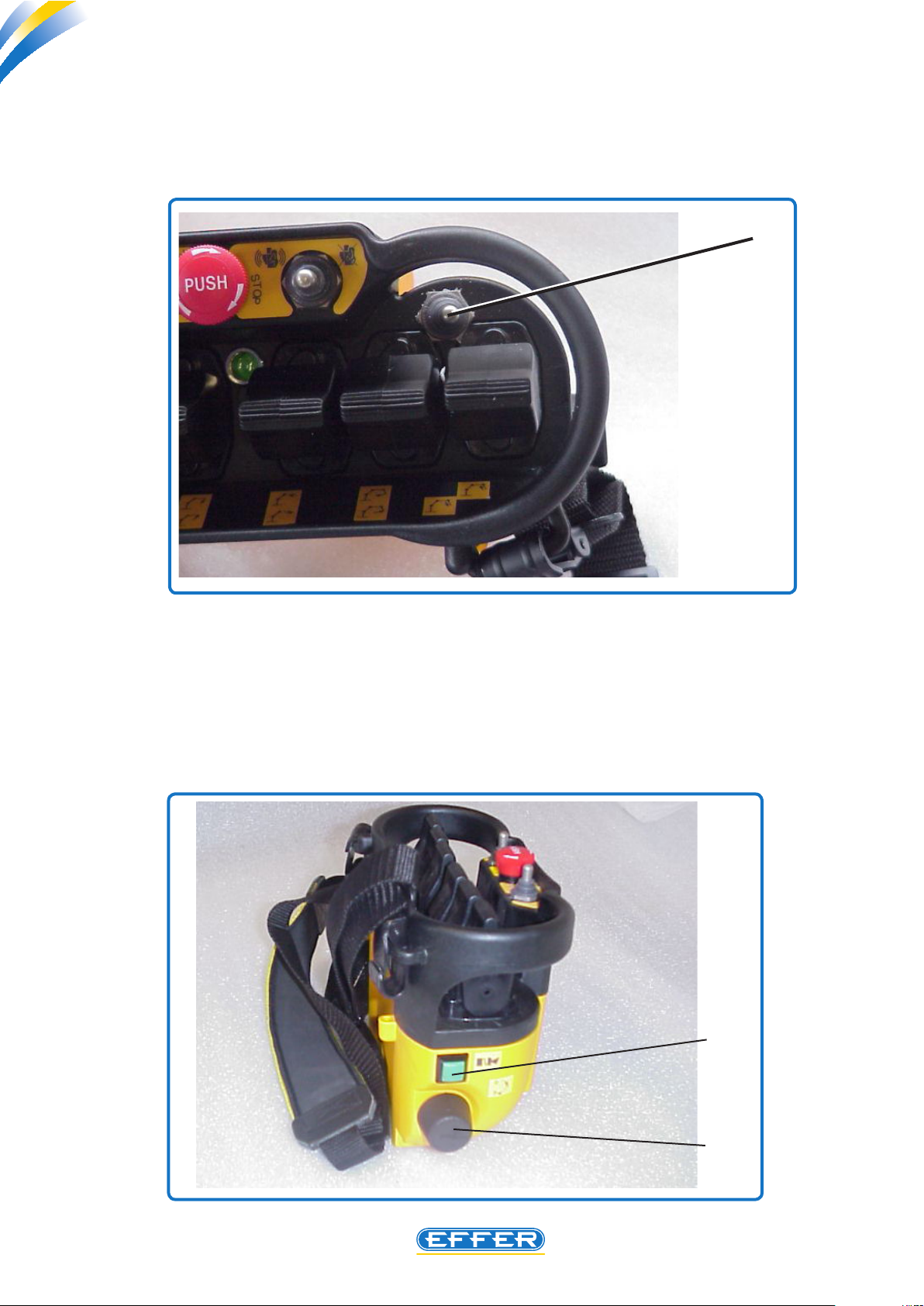
2.2.6 J- Push-button to activate the 7th and 8th function – EFFER part # 8991402 -. This
two-positions push-button is tted only in radio remote controls arranged for the operation of seven or eight
functions of the controlbank. The corresponding module is provided together with this push-button, as explained
in section 2.1.6 regarding the receiver unit.
J
899
2.2.7 F- Key to turn ON the radio remote control – EFFER part #8991246 -. Turn the key to
90° clockwise to turn ON the radio remote control: the transmitter will send a continuous beep for approximate
three seconds, then a shorter one, while the LED “C” starts ashing.
2.2.8 G- Green push-button – EFFER part #8991247 - Pressing this button after having turned the
a.m.black key, and having heard the two a.m. acoustic signals, completes the start-up procedure of the radio
remote control activation. Moreover, a positive signal is sent to a terminal inside the box for the electric accessory
connection to connect the buzzer (to identify the terminal, see section 2.1)
G
F
050
Page 19
Radio controls HETRONIC BMS1
THE POWER OF PERFORMANCE
C4.1
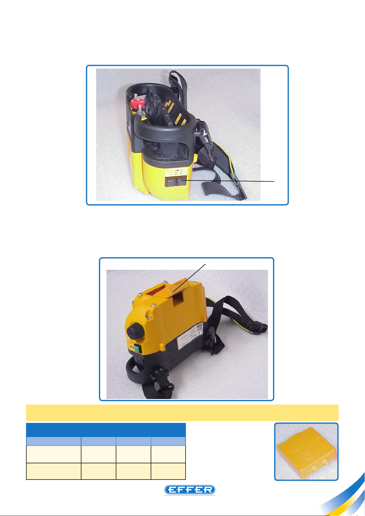
2.2.9 H- Black push-buttons – (EFFER part # 8991248 – for one push-button only). These push-but-
tons increase/decrease the truck engine rpm (positive signal sent to the wires no. 4 and no. 5 – see the section
about the receiver unit).
H
049
2.2.10 I- Battery – EFFER part # 8991007- The radio remote control is delivered with two batteries. The bat-
tery has to be slot in the compartment located below the receiver unit. The operating time of the charged batteries
is approximately 12 hours. As explained in section 2.2.3, when the capacity of the battery is nearly exhausted, the
LED “C” ashes faster than the usual, and an acoustic signal sounds. The exhausted battery inserted in the battery
charger compartment fully charges approximately in 3.5 hours. We recommend that you do not leave a charged
battery in the battery charger for a long time.
I
Note: a battery with a reduced voltage and smaller dimensions is used from the radio controls EFFER part
# 85340. The order code with the relative charger changes.
Battery code
8991007 61mm 64mm 9,6 V
8991433 61mm 54mm 3,6 V
Battery size Voltage
A B
785
B
A
19
Page 20

Radio controls HETRONIC BMS1
THE POWER OF PERFORMANCE
20
C4.1
Radio controls HETRONIC BMS1
2.2.11 L- Electronic Module – It turns the signals received by the paddles into signals that can be
transmitted via radio. On the lower side of the module of the radio remote controls delivered until the beginning
of 2001, 16 switches (ref. Z’) are located. They dene the dialogue code between the transmitter unit and the
receiver unit. In section 2.1.5, we mentioned similar switches located in the receiver unit, and we explained that
for no reason the code resulting from the switch combination should be altered. We recommend again that the
code must never be changed, as no kind of trouble can be solved by changing the dialogue code. (Electronic
module EFFER part # 8991249).
The radio remote controls delivered since the beginning of 2001 are equipped with a single part with xed code
Ref. Z’’. Electronic module EFFER part # 8991249A.
2.2.12 M- Buzzer – EFFER part # 8991250- It starts beeping when the radio remote control is turned on
and keeps on beeping for 30 seconds before the battery in the transmitter unit is exhausted.
2.2.13 N- Transmitter radio module – (EFFER part # 8991251A European Frequency and other
countries Ref. CS434) (EFFER part # 8991253A American Frequency and other countries Ref. CS458). It
transmits the radio signals processed by the module L, and sends them via radio to the receiver unit. This module
is complete with an antenna (black cable inside the transmitter, not visible from the outside).
2.2.14 O- Transmitter operation module by emergency cable - EFFER part # 8991252-
It is meant to identify the insertion of the false battery connected to the emergency cable, into the compartment
under the transmitter, instead of the standard battery. When this occurs, the module turns the signals of the paddles
from signals via radio to signals via cable (the description of this cable is explained in section 2.4).
O
N
L
Z’
897
M
Z’’
Page 21
Radio controls HETRONIC BMS1
THE POWER OF PERFORMANCE
C4.1
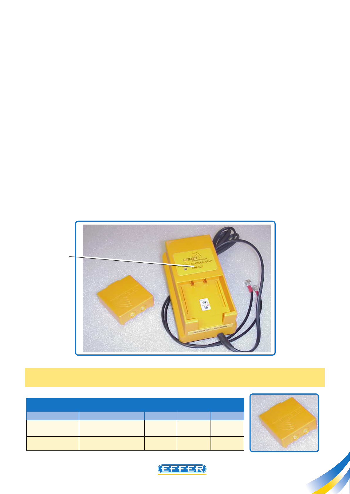
2.3 Battery charger with spare battery
The battery charger and an additional spare battery are delivered together with the radio remote control.
The battery charger operates with an operating voltage of 12 volt or 24 volt. The adjustment to the charging
voltage is performed by the battery-charger automatically, according to the input voltage. The electric connection
of the battery charger can be performed using the two black cables pre-arranged (no specic recommendations
regarding the polarity).
After a charging time of approximately 3,5 hours, the green ashing LED - ref. X - indicates that the charging
process is nished.
When the battery is fully charged, the LED starts ashing, indicating that a “preserving” charge is in progress.
However, it is advisable not to leave the charged batteries in the battery charger.
To get a long operating time out of the batteries, we recommend that you charge any battery only when it is
completely exhausted.
As already mentioned, the battery charger is protected against power polarity reversal. However, it is essential
to connect it in a position sheltered by a fuse, with voltage ON even with the truck key in the OFF position: the
voltage consumption is so small that it will not aect the truck batteries.
Alternatively, we recommend mounting an additional 5-Ampere fuse between the battery charger cable and the
connecting point on the truck.
The battery charger should be mounted inside the truck cabin, in an area sheltered by accidental hits.
As the electric contacts between the battery charger and battery are gold-plated, they do not require any special
maintenance. However, keep the two spring-contacts on the battery charger clean, and check for smooth sliding
in and out.
X
900s
Note: a battery with a reduced voltage and smaller dimensions is used from the radio controls EFFER part
# 85340. The order code with the relative charger changes.
Battery code Battery charger code Battery size Voltage
A B
8991007 8990976 61mm 64mm 9,6 V
8991433 8991434 61mm 54mm 3,6 V
B
A
21
Page 22

Radio controls HETRONIC BMS1
THE POWER OF PERFORMANCE
22
C4.1
Radio controls HETRONIC BMS1
2.4 Emergency cable
u The emergency cable allows using the radio remote control in case of faults arisen in the radio transmission
system.
It may also be used in case of exhausted batteries, so as to keep-on using the transmitter.
The cable connection point is located on the lower side of the receiver unit – see point B, section 2.1.
The false battery must be tted in the compartment located on the bottom of the transmitter unit – see section
2.2.10.
The cable length is 20 metres.
The start-up procedure for the radio remote control does not change: always follow the instructions written in
the previous sections.
u Also the pre-set adjustments and all the other optional functions t to the ado-controls do not change when
the emergency cable is used. When not at use, the cable should be stored in a compartment inside the truck
cabin. Do not store however the false battery applied to the cable end in an area subject to magnetic elds since
this could damage it denitively.
Emergency cable depends on battery size:
Battery code
Battery size Emergency cable
A B
8991007 61mm 64mm 8991254
8991433 61mm 54mm 8991477
001
Page 23
Radio controls HETRONIC BMS1
THE POWER OF PERFORMANCE
C4.1
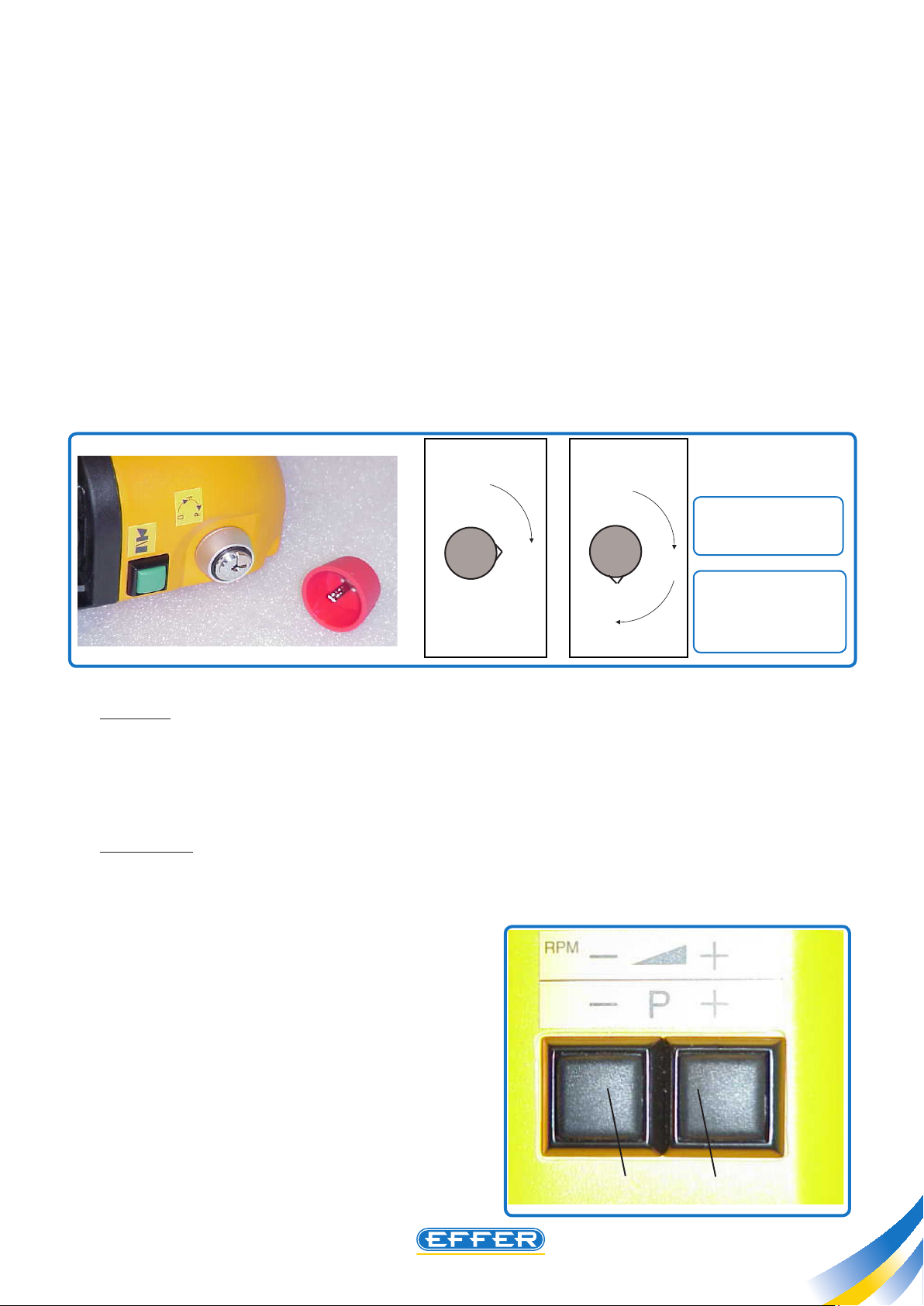
2.5 Programming red key
u Insert this key (Pos. T) to programme and customize the control paddles operation in such elds as:
-crane motions start point;
-max. speed achievable during a certain movement either at normal speed or at a reduced speed.
This key, unlike the black key, turns one quarter of rev. more, i.e: in total a rotation of half a rev.
Turn the key to the rst snap
it.
The correct procedure for the operation test and the possible adjustments is reported below.
Start the truck engine and clutch on the hydraulic pump. Provide for crane correct stabilisation and turn the radio
remote control on.
Turn the red key to the setting position- (i.e.: half a rev.), and make sure the switch on the transmitter is set at the
max. speed position (“rabbit”).
(Pos. I) to start the system, then turn it to the second snap (Pos. P) to start customizing
Switch electric
connection:
red
red wire
I
yellow/orange grey
wire
Start
T
0
T T
I
P
0
P
Programming
u First test: The rst test checks the non-operative stroke of the paddle. All crane movements must start after
performing a short “idle” stroke with all the paddles. This stroke should be as equal as possible for all the paddles,
so as to make the operator’s job easier. If you need to increase or reduce the stroke, act on the two push-buttons
placed at the left of the transmitter. While moving the paddle, press the button ref. “A” to decrease the idle stroke,
or the push-button ref. “B” to increase it. This test shall be performed for all the paddles, on both directions of
operation.
u Second test: The second test concerns the maximum stroke of the controlbank lever. At the max. operating
speed, the mechanical lever must complete the whole stroke. The test requires that you move the paddle until
its end, so as to achieve the max. speed available for that movement, and that you shift simultaneously the same
mechanical controlbank lever, thus testing that no further stroke is possible.
If both end-strokes occur simultaneously, no further
setting is required, while if there is still some mechanical
stroke available on the controlbank lever, then press the
push-button “B” until the stroke of the controlbank lever
increases up to its max. allowed position.
u Third test: The third test concerns the non-operative
stroke of the paddle, when the speed switch is turned to
the low speed position (“snail”). In order to carry out this
test, repeat in whole the a.m. procedure described for the
rst test.
A
003
B
23
Page 24
Radio controls HETRONIC BMS1
THE POWER OF PERFORMANCE
24
C4.1
Radio controls HETRONIC BMS1
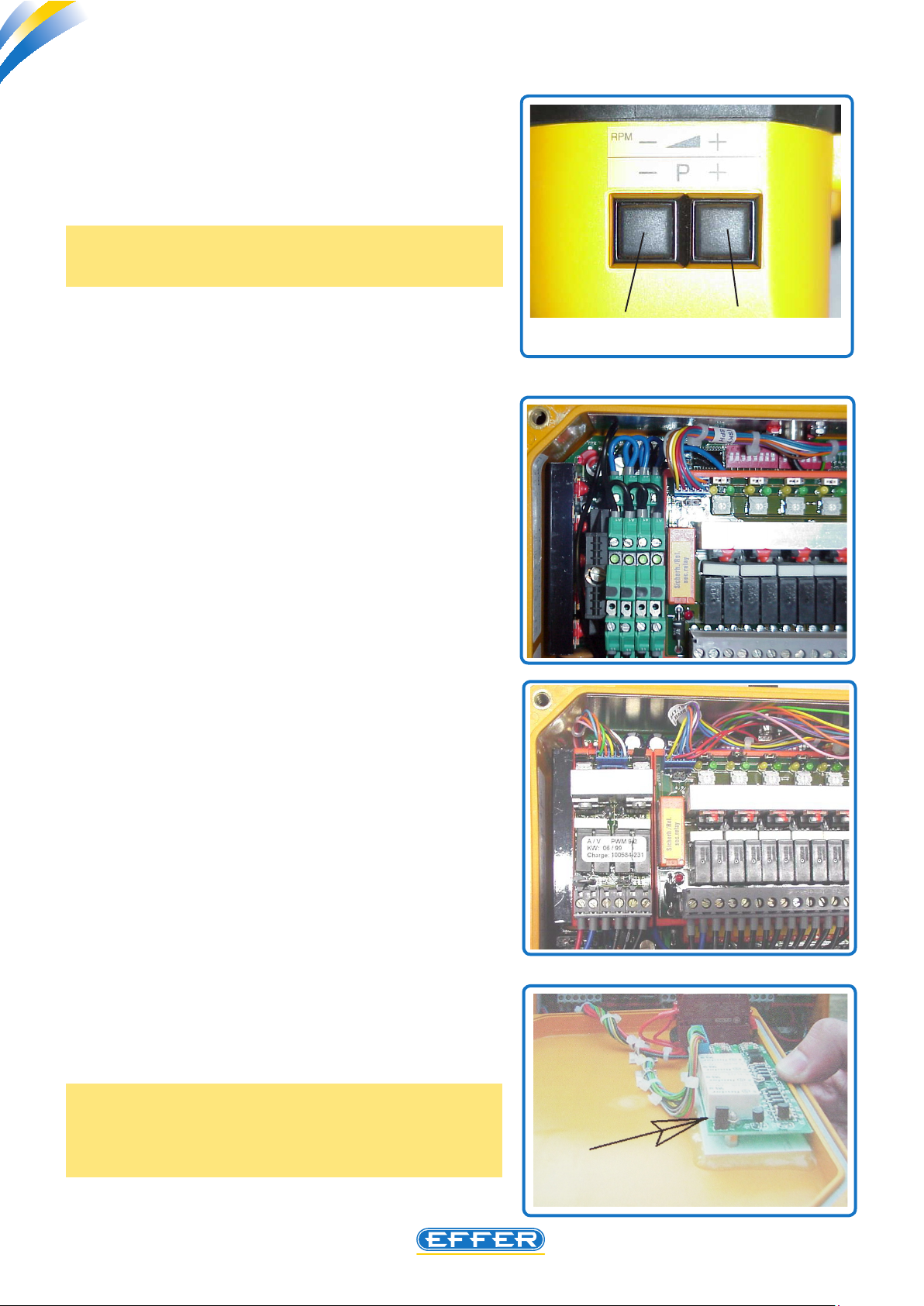
u Fourth test: The fourth test concerns the max. speed of
each movement when operating the crane at low speed. In most
of the cases, the operator wishes to adapt it to the specic jobs
he carries out.
To perform the adjustment, move a paddle, then act on the
push-buttons “A” and “B”.
Important: After any adjustment, wait for at least 10 seconds
before starting a new adjustment (this time is necessary for the
system to save in its memory the new setting data).
003
u The radio remote controls delivered until the beginning of
2001 are equipped with a receiver with an electronic module
Ref. 6’ (cap. 2.1.6). Operating speeds of the 7th and the 8th lever
are the same as the 6th and the 5th lever.
Until the beginning of 2001
u The radio remote controls delivered since the beginning
of 2001 are equipped with a receiver with an electronic module
Ref. 6’’. Operating speed adjustment for the 7th and the 8th
lever leva does not depend on the 6th and the 5th lever.
A
B
Since the beginning of 2001
When all adjustments have been completed, turn the red key
anticlockwise, then replace the red key with the black one. Finally, turn on the radio remote control, and make a whole test
of the unit.
It is recommended not to leave the red key to an un-expert
operator to avoid jeopardising the correct crane operation.
NOTE: If you have to change the operating speeds during the
work of the crane in FPI mode, before you start programming
you should apply an electrical bridge as shown in the photo
beside.
Page 25

Radio controls HETRONIC BMS1
THE POWER OF PERFORMANCE
C4.1
2.6 Procedure for the radio remote controls operation
Herebelow we summarize the procedure to be explained to the nal operator for the use of the radio remote
control:
- Turn ON the crane electric system.
- Run the truck engine, then turn on the hydraulic pump and provide for crane correct stabilisation. Make sure the
key switch (ref. P) is turned to the “radio” position.
- Make sure the emergency stop push-buttons were not pressed accidentally, especially the button located on the
transmitter (ref. A). Otherwise, the radio remote control will not operate.
- In case of radio remote controls supplied with switch for the 7th and 8th function (ref. J), make sure the switch is turned to
the position in which the supplementary functions are disabled. Otherwise, the radio remote control will not operate.
- Turn by 90° the black key (ref. F) and wait until you hear a continuous sound coming from the transmitter, then
the second faster sound. The green LED located on the transmitter will start ashing.
- Wait for at least three seconds before pushing the green push-button (ref. G) to conclude the starting
procedure.
The yellow LED (normal) will light up, while the green LED (signal), and the yellow LED (operation) will be ashing
on the receiver unit.
NOTE: This procedure is valid even if you use the emergency cable.
Turn o the radio remote control by turning the black key (ref. F) 90° anticlockwise.
RADIO
HAND
P
A
J
163
G
F
0
F
I
P
25
Page 26

Radio controls HETRONIC BMS1
THE POWER OF PERFORMANCE
C4.1
26
Page 27
Radio controls - HETRONIC BMS2
THE POWER OF PERFORMANCE
C4.2
Radio Control HETRONIC
BMS 2
GA610 BMS NOVA - XL
Features: Outreach about 100 m
Working temperature -30° ÷ +70° C
Transmission Power < 10 mW
Data size 2400/4800 baud
Frequency Band 70 cm (400÷470 MHz, 868÷870 MHz)
Protection degree IP 65
27
Page 28
THE POWER OF PERFORMANCE
Radio controls - HETRONIC BMS2
Radio controls - HETRONIC BMS2
C4.2
1- Operation
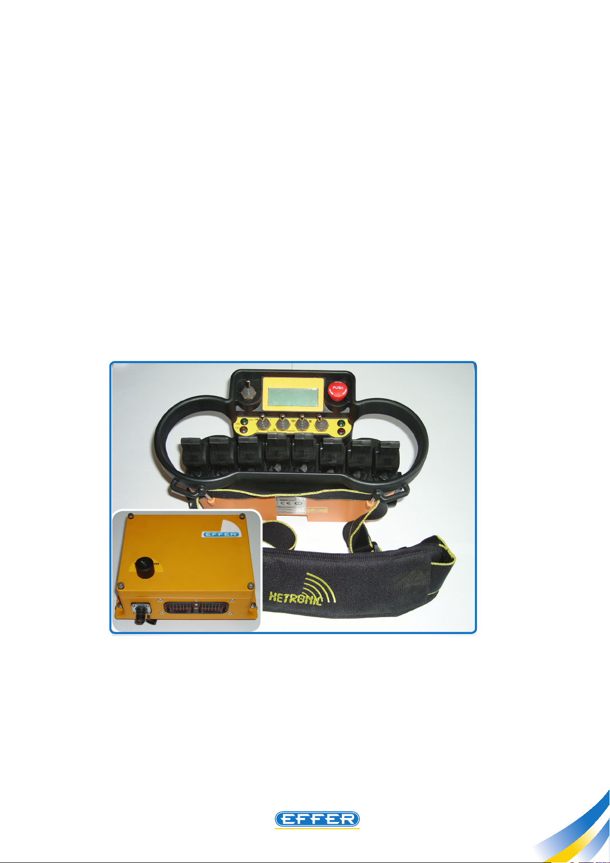
u The radio control is made up of a transmitting unit, also called pushbutton panel, which is equipped with a
support to be attached to the belt. As a standard feature the pushbutton has 8 single control levers to carry out
8 crane functions.
u The receiving unit, positioned near the manual control bank, dialogues only with its respective transmitting
unit: the recognition code is inserted into ADMO, and ensures that the crane can move only after an intentional
action by the crane operator.
u Whenever you operate a control lever or one of the operation switches of ancillary functions (placed on the
pushbutton panel), this information is transmitted, through the radio signal, to the receiving unit.
The receiving unit decodes the radio signal and changes it into an electrical control that operates the crane control
bank or one of the ancillary functions - if connected
u During the work, the operator can carry out more movements at the same time and the crane handling occurs
in a proportional way: if small shifts on the control levers of the pushbutton panel are made, with respect to the
neutral position, crane movements at low speed will consistently be run, and the more the control lever is shifted,
the higher is the crane operating speed.
N.B: It is recommended to perform any technical operation on radio control only after having completely
read the following chapters. Therefore, you will have the sucient technical knowledge to carry out all
the necessary settings for optimal operation and to carry out some operations in case of any operating
failures.
N.B: We remind you that power supply to radio control must be cut o, by removing electrical cables from
truck batteries, in case welding operations on crane or truck are required.
28
1930744
Page 29

Radio controls - HETRONIC BMS2
THE POWER OF PERFORMANCE
C4.2
2 - Radiocontrol, type “GA610 BMS NOVA – X L”
u his radio control is particularly appreciated for the small size of the receiving unit (160 x 210, depth 90 mm)
It may be supplied with direct current, both 12 volt and 24 volt.
u In case of 24-volt connection by operating six functions at the same time, the maximum absorption is 3.8
amp.
u The protection fuse inside the receiving unit, has a size of a maximum of 7.5 A.
u The transmitting unit has a form which ressembles a binocular.
u The standard equipment includes:
1 Receiving unit Refer to paragraph 2.1
2 Transmitting unit Refer to paragraph 2.2
3 Battery charger with spare battery Refer to paragraph 2.3
4 A 20-m long emergency cable Refer to paragraph 2.4
5 A red key required to run programming Refer to paragraph 2.5
6 Antenna on receiving unit
1
2
5
3
4
6
29
Page 30

THE POWER OF PERFORMANCE
Radio controls - HETRONIC BMS2
Radio controls - HETRONIC BMS2
C4.2
2.1 Receiving unit
u This radio remote control is specially appreciated for the reduced size of its receiver unit (160 x 210, depth:
90 mm). It is available with either 12 V. DC or 24 V. DC.
u Three possible receiver unit congurations are available:
1) for HAWE CONTROL BANK, no. 8 outputs with current signals (Ampere)
2) for DANFOSS CONTROL BANK, no. 8 outputs with voltage signals (Volt)
3) Both HAWE CONTROL BANK and DANFOSS CONTROL BANK, are equipped with signal trasmission between receiver and DMU by CAN BUS system
u There are two dierent versions of receiving modules according to frequency (Europe 434MHz or America
458 Mhz )
u Display on a side, to view Error codes or receiving unit state
The receiving unit is provided with two electrical connectors:
A - For cable connection to operate the control bank and for power supply of the receiver
B - For the electrical cable connection for the emergency operation
- For the electrical cable connection for programming through computer
THE CONNECTOR FITTED TO POINT A IS PROVIDED WITH 70 POLES: HERE FOLLOW THE FUNCTIONS OF MAIN
POLES
30
B
A
Page 31

Radio controls - HETRONIC BMS2
THE POWER OF PERFORMANCE
C4.2
2.2 Electrical connections
u There are two types of receiving units for DANFOSS and HAWE control banks. The connector conguration
changes according to the two cases.
u The two tables in the following pages refer to pins on
connectors and to the function of the electric wire.
The rst column shows the numbers on the connector, the third
column shows the marks printed on the wire ends.
70-pole connector for DANFOSS control bank (refer to table 1)
NOTE: the proportional signal of the two directions ranges from 6V to 18V; the proportional signal of the two
directions shifts from 6 Volts to 18 Volts.
When the lever is in the middle postion the signal sent to the control bank coil is 12 Volts.
70-pole connector for HAWE control bank (refer to table 2)
NOTE: When the lever is at the two maxium ends of stroke, sthe proportional signal of the two directions shifts
from 0.4 A. to 1A. , considering a 24-Volt voltage.
31
Page 32

THE POWER OF PERFORMANCE
Radio controls - HETRONIC BMS2
Radio controls - HETRONIC BMS2
C4.2
TABLE 1
n° Pin
70-pin
Function Wire end mark
connector
57 GND
X10 pin ANA (GND) Input negative signal
59 +24V X10 pin B Input positive signal
45
17
61
30
62
60
18
32
19
33
31
EM. radio X10 pin C Input positive signal
HSS (output) X13 pin 1 Output positive signal
PLE (input) X13 pin 2 Input positive signal
FPI (output) X13 pin 3 Output positive signal
FPI (input) X13 pin 4 Input positive signal
Block 2 (input) X13 pin 5 Input positive signal
Start Engine X14 pin 1 Output positive signal
Stop Engine X14 pin 2 Output positive signal
RPM+ X14 pin 3 Output positive signal
RPM- X14 pin 4 Output positive signal
AUTORPM X14 pin 5 Output positive signal
DANFOSS
Description
34
15
29
20/4
21
63
35
22
64
36
23
65
37
24
66
38
25
67
39
26
68
40
27
69
41
28
70
42
11
12
CLAXON X14 pin 6 Output positive signal
Aux 1 X14 pin 7
Aux 2 X14 pin 8
Spare signal
Spare signal
Dump Valve NA (activ.) Output positive signal
8° Channel (V8) 3 G/V (GND) Output negative signal
1 Black (Prop. Signal) Output positive signal for directions
2 Red ( + 24V) Output positive signal
7° Channel (V7) 3 G/V (GND) Output negative signal
1 Black (Prop. Signal) Output positive signal for directions
2 Red ( + 24V) Output positive signal
6° Channel (V6) 3 G/V (GND) Output negative signal
1 Black (Prop. Signal) Output positive signal for directions
2 Red ( + 24V) Output positive signal
5° Channel (V5) 3 G/V (GND) Output negative signal
1 Black (Prop. Signal) Output positive signal for directions
2 Red ( + 24V) Output positive signal
4° Channel (V4) 3 G/V (GND) Output negative signal
1 Black (Prop. Signal) Output positive signal for directions
2 Red ( + 24V) Output positive signal
3° Channel (V3) 3 G/V (GND) Output negative signal
1 Black (Prop. Signal) Output positive signal for directions
2 Red ( + 24V) Output positive signal
2° Channel (V2) 3 G/V (GND) Output negative signal
1 Black (Prop. Signal) Output positive signal for directions
2 Red ( + 24V) Output positive signal
1° Channel (V1) 3 G/V (GND) Output negative signal
1 Black (Prop. Signal) Output positive signal for directions
2 Red ( + 24V) Output positive signal
CAN -H CAN pin A
CAN -L CAN pin B
32
Page 33

Radio controls - HETRONIC BMS2
THE POWER OF PERFORMANCE
C4.2
TABLE 2
n° Pin
70-pin
connector
57 GND
59 +24V X10 pin B Input positive signal
45
17
61
30
62
60
18
32
19
33
31
Function Wire end mark Description
X10 pin ANA (GND) Input negative signal
EM. radio X10 pin C Input positive signal
HSS (output) X13 pin 1 Output positive signal
PLE (input) X13 pin 2 Input positive signal
FPI (output) X13 pin 3 Output positive signal
FPI (input) X13 pin 4 Input positive signal
Block 2 (input) X13 pin 5 Input positive signal
Start Engine X14 pin 1 Output positive signal
Stop Engine X14 pin 2 Output positive signal
RPM+ X14 pin 3 Output positive signal
RPM- X14 pin 4 Output positive signal
AUTORPM X14 pin 5 Output positive signal
HAWE
34
15
29
20/4
21
63
35
22
64
36
23
65
37
24
66
38
25
67
39
26
68
40
27
69
41
28
70
42
11
12
CLAXON X14 pin 6 Output positive signal
Aux 1 X14 pin 7
Aux 2 X14 pin 8
Dump Valve NA (activ.) Output positive signal
8° Channel (V8)
1 Brown (GND)
Spare signal
Spare signal
Output negative signal
2 Blue (DIR. A) AMPERE signal
3 Black (DIR. B) AMPERE signal
7° Channel (V7)
1 Brown (GND)
Output negative signal
2 Blue (DIR. A) AMPERE signal
3 Black (DIR. B) AMPERE signal
6° Channel (V6)
1 Brown (GND)
Output negative signal
2 Blue (DIR. A) AMPERE signal
3 Black (DIR. B) AMPERE signal
5° Channel (V5)
1 Brown (GND)
Output negative signal
2 Blue (DIR. A) AMPERE signal
3 Black (DIR. B) AMPERE signal
4° Channel (V4)
1 Brown (GND)
Output negative signal
2 Blue (DIR. A) AMPERE signal
3 Black (DIR. B) AMPERE signal
3° Channel (V3)
1 Brown (GND)
Output negative signal
2 Blue (DIR. A) AMPERE signal
3 Black (DIR. B) AMPERE signal
2° Channel (V2)
1 Brown (GND)
Output negative signal
2 Blue (DIR. A) AMPERE signal
3 Black (DIR. B)) AMPERE signal
1° Channel (V1)
1 Brown (GND)
Output negative signal
2 Blue (DIR. A) AMPERE signal
3 Black (DIR. B) AMPERE signal
CAN -H CAN pin A
CAN -L CAN pin B
33
Page 34
THE POWER OF PERFORMANCE
Radio controls - HETRONIC BMS2
Radio controls - HETRONIC BMS2
NOTE: On CAN Dynamic version, (available only with DMU PLUS) pins 30 , 62 and 60 are not used. The wire is
not even connected to pin 30, and in place of it, pin 4 is connected; it signals when the radio is turned to REMOTE
mode. (This signal will be present on pin 3 of X13 and used by DMU to control CAN communication.)
NOTE: In the conguration of crane not equipped with DMU, connectors X10, X13, X14 are not connected and
the Blinker cable is used and connected to pins 57 (GND) and 16 (operation).
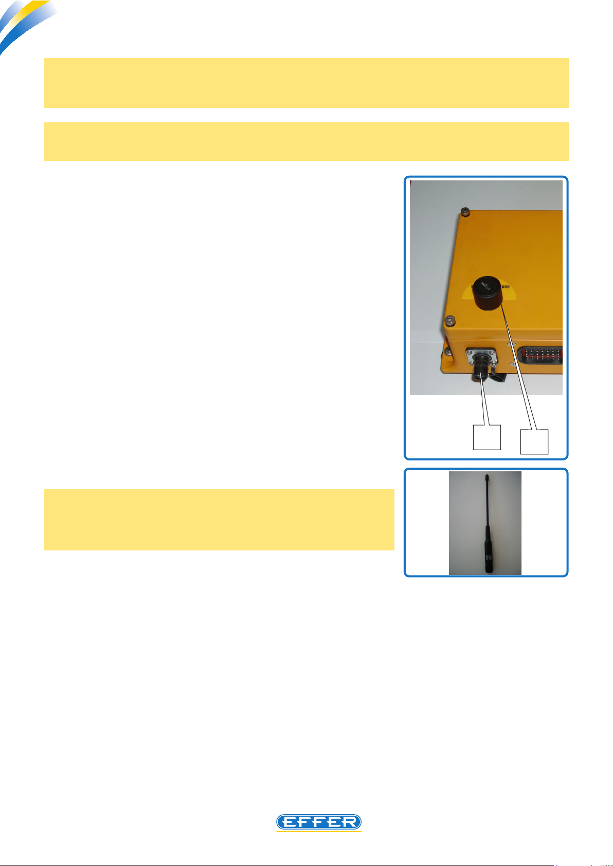
The connector B is provided with 4 poles: the same connector is used for
connecting the cable for programming through computer, and the electrical cable provided with the crane is required for the radio control use in
case of an emergency.
This emergency may result from a failure in the rice-transmitting system of
the radio, or from the inability to use the system due to radio transmission
conicts with other electronic devices in the area where you work with
the crane.
C4.2
The receiving unit cover is provided with the key selector C with which you
select the select mode to handle the crane:
- RADIO, the crane is handled using the radio control
- HAND, the crane is handled by operating the manual levers placed
on the hydraulic control bank.
The antenna is tted to the receiving unit upper part.
NOTE: to ensure maximum reception of radio signals emitted by the
transmitting unit, the antenna must be left free in a high position of the
crane: any guard tted to the receiving unit, for aesthetical purposes,
may jeopardise the radio control operation.
B
C
34
Page 35
Radio controls - HETRONIC BMS2
THE POWER OF PERFORMANCE
C4.2
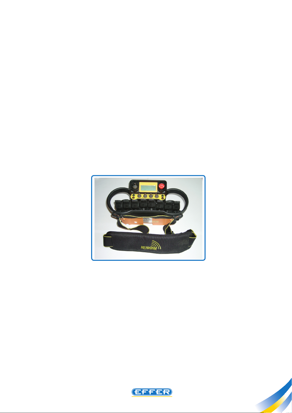
2.3 Pushbutton panel (Transmitting unit)
- Standard conguration includes 8 levers (handles/joystick) in line for proportional function control.
Upon request it is possible to have a pushbutton panel with cross joystick.
- Some switches are provided for the main functions ON/OFF (FPI, HSS, SNAIL, Aux., Truck, auxiliary functions)
- EMERGENCY button
- On the right side a black key is provided for for switch ON and switch OFF of the remote control: by inserting
the red key in the same position and by turning it a half of a turn, it is possible to adjust speed and movements
- A display (4 lines 20 characters ) is provided according to the required accessories.
- Transmission module inside the transmitting unit available : mono-directional in the case without display,
or bi-directional in the case with display.
- On a transmitter unit side you nd the connection point of the electric cable to connect the trasmitter to
the receiver, so as to use the crane in “Remote Control mode”.
35
Page 36
THE POWER OF PERFORMANCE
Radio controls - HETRONIC BMS2
Radio controls - HETRONIC BMS2
C4.2
3 - Instructions for use
u Read the instructions carefully and completely before you carry out any repair to the crane.
u The BMS-2 system is used with various types of transmitting units, therefore, it is possible that the pictures
and the drawings in these instructions for use do not represent exactly the transmitting unit. If you check
the Technical Documentation of the specic transmitting unit delivered with the documentation of the
specic crane, you will nd the wiring/functional diagram of the radio control panel tted to the crane.
3.1 Numbers of production and system
u Any technical explanation you may require, or the request of spare parts, must always be accompanied by
the numbers of production and system of the transmitting and receiving units.
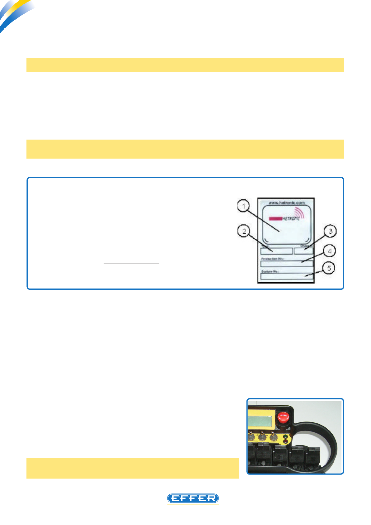
The numbers are on the label on the unit outer part.
1. Special homologations, such as BTZ, FCC, CE, etc. and HF part.
2. Type of transmitting or receiving unit.
3. Frequency channel
4. Production number – The 1st position shows the place of produc-
tion (1=H-Germany, 2=H-Malta, 3=H-USA, 4=H-Italy).
The 4 following positions show the month and the year of produc-
tion.
The last 6 positions are the system address.
5. System number -Hetronic identication number
of transmitting or receiving unit.
3.2 Not authorised spare parts
u Use only original spare parts. The use of not original spare parts may signicantly aect the functionality,
the duration and the safety of this system and terminates the warranty. EFFER denies liability for any claim,
damage or injury even fatal to people, resulting from the use of not original spare parts.
3.3 Emergency stop function
u The most important feature of remote radio control is the emergency
stop. Whenever you operate a transmitting unit joystick, to handle
the crane, a functionality control of the emergency stop button is
automatically carried out.
When the emergency stop button is pressed, the relay module trig-
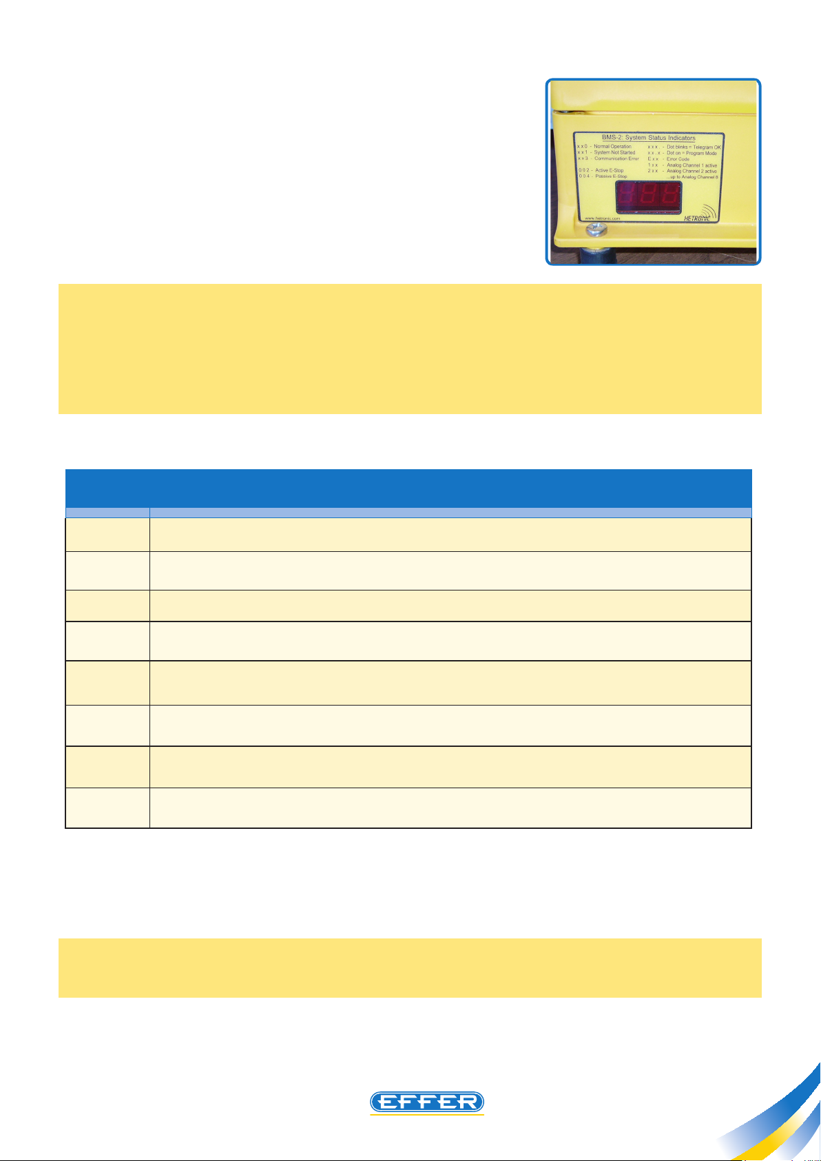
The BMS-2 receving unit dispaly shows now “0 0 2” which indicates
36
gers a lock of all the movements of the machine. The receiving unit is
turned to safety mode.
the state “emergency stop on (pressed)” which is turned on.
Page 37
Radio controls - HETRONIC BMS2
THE POWER OF PERFORMANCE
To restart the system, just release the emergency stop button: it reacts faster
than any other function, then push START. When the emergency stop is
turned on, the system ignores all the other signals.
When the emergency stop is activated, the system disregards all other
signals.
During the operation steps of radio control, the display sho “0 0 1” to indicate that the system is waiting for the
start, i.e. the green button next to the transmitting unit must be pressed, to enable radio communication.
Once the radio control operation step is completed, if the display shows “0 0 4” this shows that radio com-
munication between the transmitting unit and the receiving unit has not been operated; if this numbering
remains after other attempts, a failure is present.
C4.2
Codes DISPLAY MESSAGES ON THE RECEIVER
xxO
xx1
xx2
xx3
xx4
000
00.0
1xx
system started, ready for use
System powered, waiting for reset signal (Klaxon Button on transmitting unit)
The STOP mushroom-shaped emergency button of the transmitting unit is pressed
The radio control is still working, but the radio signal is very weak: radio communication may
go dead
the radio control is properly powered, the radio signal between the transmitting and receiving
units is missing (transmitting unit turned o or run-down battery)
The ashing point after the third number indicates that the transmission is operational. Each
ash indicates the receipt of a telegram
The ashing point after the second number indicates that the transmitting unit is turned to
program mode (red key inserted)
(1xx up to 8xx) one or more transmitting unit joystick have been enabled and the numbers (which
appear alternately) indicate which channels are enabled.
3.4 Safety
IMPORTANT: Always turn o receiving unit power supply before carrying out welding works on the crane/truck,
by disconnecting the electric cables of the batteries.
37
Page 38

THE POWER OF PERFORMANCE
Radio controls - HETRONIC BMS2
Radio controls - HETRONIC BMS2
C4.2
3.5 Setting function speeds
NOTE: Not valid for cranes equipped with DMU 3000 PLUS.
For these settings the receiving unit must be properly powered and the crane hydraulically supplied.
Remove the black key from transmitting unit ignition switch.
u Insert the red programming key T in its place.
u Turn on the transmitting unit: an acoustic signal is emitted.
u Wait about 3 sec. until you hear the second acoustic signal.
u Turn the key an additional ¼ of turn up to the position of the programme (this is possible only with the red
programming key ). Hold down the Start/acoustic signal key A for at least 1 sec.
T
A
- Setting minimum speed.
Move slowly the joystick until you hear a beep emitted by
DMU. Hold the joystick in this position. Now you can set
the speed of this function with the help of the buttons
specially dedicated to programming, on the transmitter.
- Press in direction “+” to increase the speed and in direction “-” to reduce it.
We recommend that you set the speed of the function
on a level which is as low as possible. In this way it will be
possible to obtain a proportional excursion on the joystick
much broader and uniform.
0
T T
I
P
0
I
P
- Setting maximum speed.
Move the joystick until its maximum position. Press “+” to increase speed and “-” to reduce it.
The receiving unit can program one single function at a time. Make sure that (with the cross-type joystick) only
a command at a time is controlled. When setting of the function in one direction is nished, proceed with the
other directions and functions as described above.
NOTE: the function “snail” is independent from the function “hare”. So, if you need to change the speed of the
function “snail”, select it before.
When the required setting is completed, wait at least 10 sec. before disconnecting the transmitting unit. The
new values are stored automatically in the system.
38
Page 39
Radio controls - HETRONIC BMS2
THE POWER OF PERFORMANCE
NOTE: All the remote radio controls are controlled by EFFER with settings pre-adjusted in ADMO key.
However, it is possible to replace electronic boards, encoders or decoders, but ADMO key must always be reinstalled
on the new board as this is the true identity card of the system.
If you request a spare radio control, remember to provide the crane identication codes to be able to receive it
with the correct settings.
C4.2
3.6 Starting
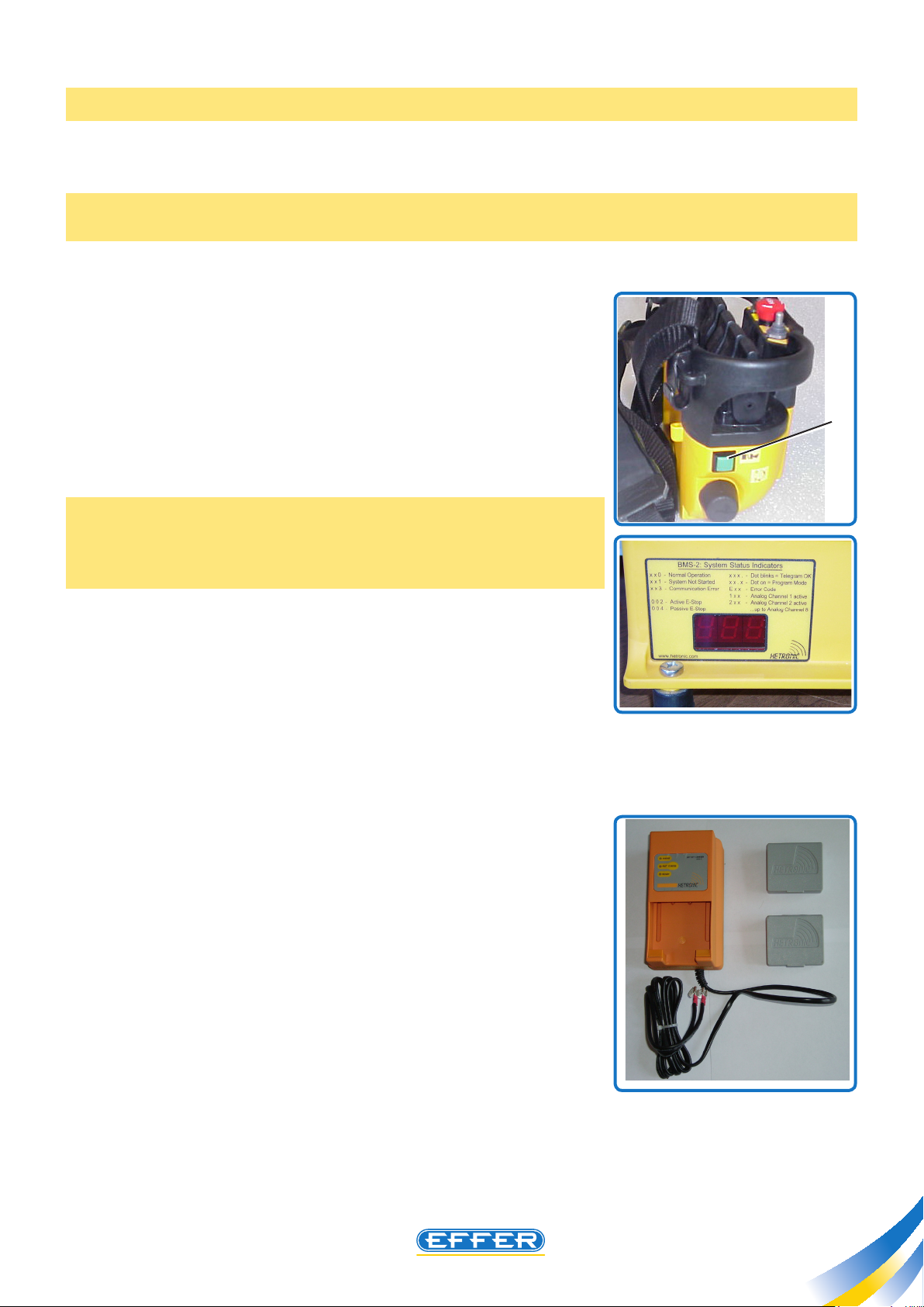
u 1. Turn on the transmitting unit. You will hear a short acoustic signal.
u 2. Wait for the 2nd acoustic signal (about 3 sec.)
u 3. Press Start/acoustic signal button G again.
G
The system correct operation is reported on the receiving unit display ( “0
0 0” must appear).
If the control elements, the joystick or the switch lever are not turned
to the “o” (neutral) position, the transmitting unit will not be operated by pressing the Start/acoustic signal button.
3.7 Low battery level
u If, in the transmitting unit, the battery voltage drops below 3.4 volt, the
system signals a state of undervoltage. The red and green warning lights on
the trasmitter are lighted up and ash alternately. From that moment, you have
10 minutes at disposal to position the crane/machine in a safe place and to
turn o the transmitting unit. After 9 minutes the beeper will also come into
operation and after approx. 1 minute the radio control turns OFF.
You therefore have a minute of time before the system automatically switches
to safety mode. Further to this time disconnection, the transmitting unit sends
an emergency stop signal and all the movements of the crane or machine
are stopped.
To reboot the system, it is necessary to insert a charged battery in the transmitting unit.
39
Page 40
THE POWER OF PERFORMANCE
Radio controls - HETRONIC BMS2
Radio controls - HETRONIC BMS2
C4.2
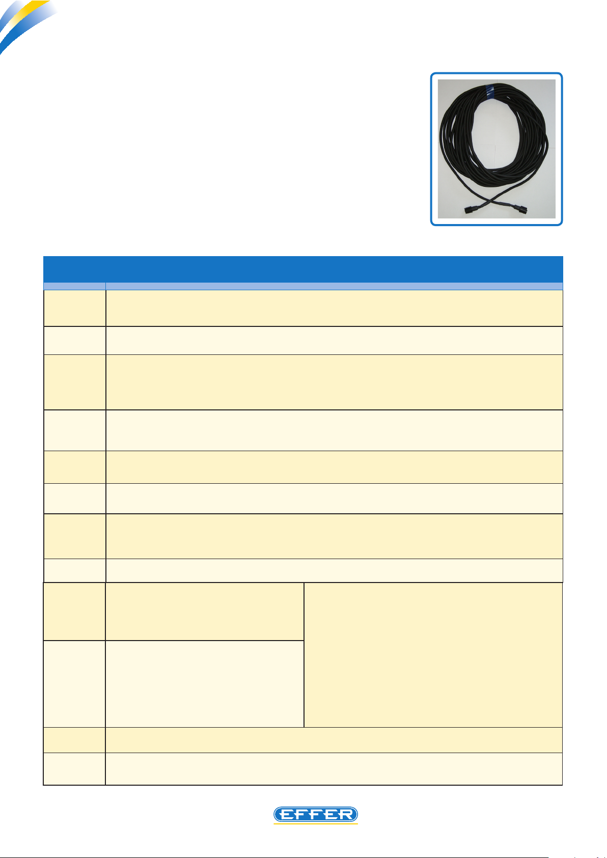
3.8 Optional control by cable
u This option allows you to operate the crane while the transmitting unit and
the receiving unit are connected with a cable. This is useful in situations where
there is radio noise or when the absence of a charged battery makes remote
transmission impossible. The cable supplies the transmitting unit with power, so
battery is not required. The system works even when battery is not in the battery
compartment.
3.9 Error localization
u If the system does not work after a normal starting, look at the enclosed table to identify error localization,
to check the cause and determine a remedial action.
Codes
E00
E08
E09
E10
E11
E12
E13
DISPLAY MESSAGES ON THE RECEIVER
( EOO up to E07 ) a transmitting unit joystick is faulty: Verify that electric wiring has not been disconnected under the joystick, if you cannot nd any failure replace the joystick.
the radio control operated, is absorbing a current value which is too high: a short circuit in electric
wiring, on actuators or on the proportional modules has probably occurred.
During its use the radio control absorbs a current value which is too high: a short circuit in electric
wiring, relating to digital outputs from 1 to 5 and Y0 or in the outputs (pin 20, 34, 19, 33, 18, 32 of
the 70-pole connector) has probably occurred.
During its use the radio control absorbs a current value which is too high: a short circuit in electric
wiring, relating to digital outputs from 6 to 11 or in the outputs (pin 17, 31, 16, 30, 15, 29 of the 70pole connector) has probably occurred.
the radio control is powered with a voltage value which is higher than allowed: check the functionality of batteries that supply the radio control .
the radio control is powered with a voltage value which is lower than allowed: check the functionality of batteries that supply the radio control .
for the proper operation of radio control, a solenoid valve is tted to the crane hydraulic circuit with
the “safety” function: there is a problem on electric wiring that supplies this solenoid valve with
power, or on the solenoid valve coil.
E14
E15÷E22
E23÷E30
E31
E32÷E39
40
wrong voltage at OUT1 outlet (start radio).
wrong input voltage to control bank
module.
codes E15 ÷ E22 correspond to control
bank module from 1 ÷ 8.
wrong proportional control voltage to
control bank module.
codes E23
bank module from 1 ÷ 8.
Short-circuit detected on one of the proportional outlets
Error signal received (Danfoss) from control bank module.
codes E32
÷ E30 correspond to control
÷ E39 correspond to control bank module from 1 ÷ 8.
1. check that cable corresponding to the module cable
isn’t damaged or short-circuited.
2. check the correct operation of the electric module on
hydraulic control bank.
In order to nd out the cause of the error code in the
radio or in the electric module of the control bank,
exchange the control bank control connectors: if the
code is still present, the fault is in the radio. Otherwise,
check the correct operation of the electric module of
the control bank.
Page 41

Radio controls - HETRONIC BMS2
THE POWER OF PERFORMANCE
C4.2
Codes
E40
E42
E50÷E62
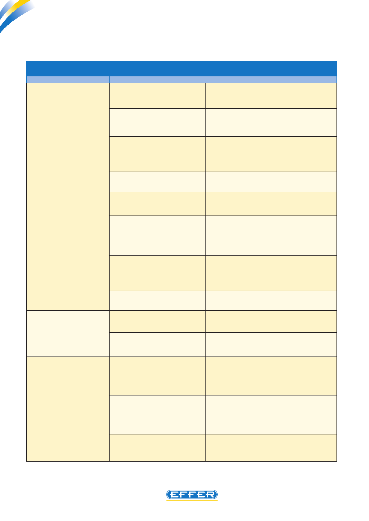
Below you can nd the description of further problems that may arise, with possible causes and solutions
Problems Possible causes Remedies
The system does not run
after normal starting
Communication error between the DMU and the radio control: the CAN-BUS cable could be damaged or the radio control is faulty.
it indicates that you want to operate the radio control while having a transmitting unit joystick not in a
central position: check the joystick position, otherwise, there is a problem inside the radio control
These numbers indicate the presence of a problem with the electronic board inside the receiving
unit: it needs repair by a service center
At start, an alarm was activated Press the Start button again.
DISPLAY MESSAGES ON THE RECEIVER
The transmitting unit is tur-
ned on, but does not
transmit (the power
green warning light is
not on).
The joystick or the control lever
are not in central position.
Emergenc y stop mushroom-
shaped button pressed.
Run-down battery. Check the battery and replace it with a fully
The receiving unit is not supplied
with power.
Run-down battery. Replace the battery with a fully charged one.
Fuse in the receiver damaged. Check the fuse and replace it if necessary.
Make sure all the joystick and the control levers
are in a central position when you press the
Start button.
Release the Emergency stop mushroom-
shaped button.
Reboot the system by pressing twice the Start
button.
charged one, if necessary.
Check the diagnostic window on the receiving
unit side, to make sure that this is powered.
Make sure that the system grounding is
on the machine negative battery terminal.
The display also shows a normal transmission, the failures and the emergency stop
states .
Faulty key switch. Check the key switch wiring.
Replace the switch, the wiring or contact ele-
ments.
Malfunction in the encoder
board.
Contact EFFER.
41
Page 42
THE POWER OF PERFORMANCE
Radio controls - HETRONIC BMS2
Radio controls - HETRONIC BMS2
Problems Possible causes Remedies
C4.2
The transmitting unit trans-
mits (the power green
warning light is on),
but the machine does
not react
Emergenc y stop mushroom-
shaped button pressed.
Transmitting unit outside the
operating range.
The joystick or the control le-
vers were not in central position when the Start key was
pressed.
The receiving unit is not pow-
ered.
The receiving unit fuse is burnt. Check all fuses and if necessary replace them.
Malfunction of the transmitting
unit emergency stop.
Malfunction of the receiving unit
emergency stop. The red warning light of the emergency stop
on the decoder board is on.
Malfunction of emergency stop
module.
Pull the Emergency stop mushroom-shaped
button and press the Start/acoustic signal
button.
Take the transmitter back to the receiving
unit range. Press the Start/acoustic signal
button.
Make sure all the joystick and the control levers
are in a central position when you press the
Start button.
Restore power supply.
Check that the emergency stop is not damaged.
Check that the wiring has no interrupted
or loose wires. Repair or replace the mushroom-shaped emergency stop button or
the wiring.
Check the wiring on emergency stop module,
on the decoder one and on emergency stop
decoder module. Secure all loose connections.
Replace the emergency stop module.
The cycle of movement of
all machine functions is
constantly interrupted.
The movement cycle of
some machine func tions is continuously
interrupted.
Loose or not tted antenna of the
receiving unit.
Loose receiving unit sockets. Check all sockets.
Loose wiring of machine move-
ment.
Loose receiving unit sockets. Check all sockets.
Malfunction of decoder board
Secure or replace the antenna.
Check the receiving unit wiring towards the
socket and from the socket to all machine
users .
Contact EFFER.
42
Page 43

Radio controls - HETRONIC BMS2
THE POWER OF PERFORMANCE
3.10 Spare parts
Below is the complementary list of parts that can be ordered as spare parts :
Description EFFER code
Linear joystick 8991814
Plug to t instead of the joystick not used in the transmitter 8991815
CABLE 3m for HAWE DIN CONTROL BANK 8991816
CABLE 3m for DANFOSS AMP CONTROL BANK 8991817
C4.2
RADIO MODULE - in the transmitter, EUROPA frequency 8991818
RADIO MODULE - in the transmitter, EUROPA frequency 8991819
RADIO MODULE - in the transmitter, USA frequency 8991820
RADIO MODULE - in the transmitter, USA frequency 8991821
ANTENNA, external for the receiver 8991954
REMOTE/MAN. switch on the receiver 8991955K
Speed programming cable for PC 9396060
Complete transmitting unit, STD NOVA-XL Europa 8991956
Complete transmitting unit, STD NOVA-XL USA 8991957
Complete transmitting unit, STD NOVA-XL Europa+Display 8991958
Complete transmitting unit, STD NOVA-XL USA+Display 8991959
43
Page 44
THE POWER OF PERFORMANCE
Radio controls - HETRONIC BMS2
Radio controls - HETRONIC BMS2
C4.2
4 - Setting instructions by PERSONAL
COMPUTER
Introduction
u Setting by personal computer (of the 6 functions listed below) is available for the following radio controls
congurations:
1) Radio control Hetronic BMS2 installed on crane with an electro-hydraulic load limiting device .
2) Radio control Hetronic BMS2 installed on crane with load limiting device type DMU.
3) Radio control Hetronic BMS2 installed on crane with load limiting device type DMU 3000 PLUS (i.e., cranes
equipped with DYNAMIC CAN.
NOTE: for crane congurations of step 3) it is ABSOLUTELY NECESSARY using a personal computer to modify any
function.
u The radio control HETRONIC BMS2 tted to EFFER cranes is supplied with an operating speed adjustment.
These speeds are not only the result of our experience, but are also designed according to the structural project
of the specic cranes.
Using the software indicated below it is possible to have access to some parameters which can be changed and
customized according to possible customer requirements. The indicated parameters are the following:
Parameters
1- direction for analogue functions (movement direction of transmitter joystick)
CRANE
FUNCTION
PLE
FUNCTION
The operating specications are described in section “Changing the parameters”.
Please note that the settings which were originally set, are included in the technical brochure, laid down
by us, relating to the features of the specic project, and NO change in the parameters not listed above is
allowed .
2- ramp start value (movement speed-up start ramp)
3- ramp stop value (movement slowing down stop ramp)
1- stop value (maximum speed adjustment in PLE mode)
2- ramp start value (start ramp for movement speed-up in PLE mode)
3- ramp stop value (stop ramp for movement slowing down in PLE mode)
44
Page 45
Radio controls - HETRONIC BMS2
THE POWER OF PERFORMANCE
Necessary equipment
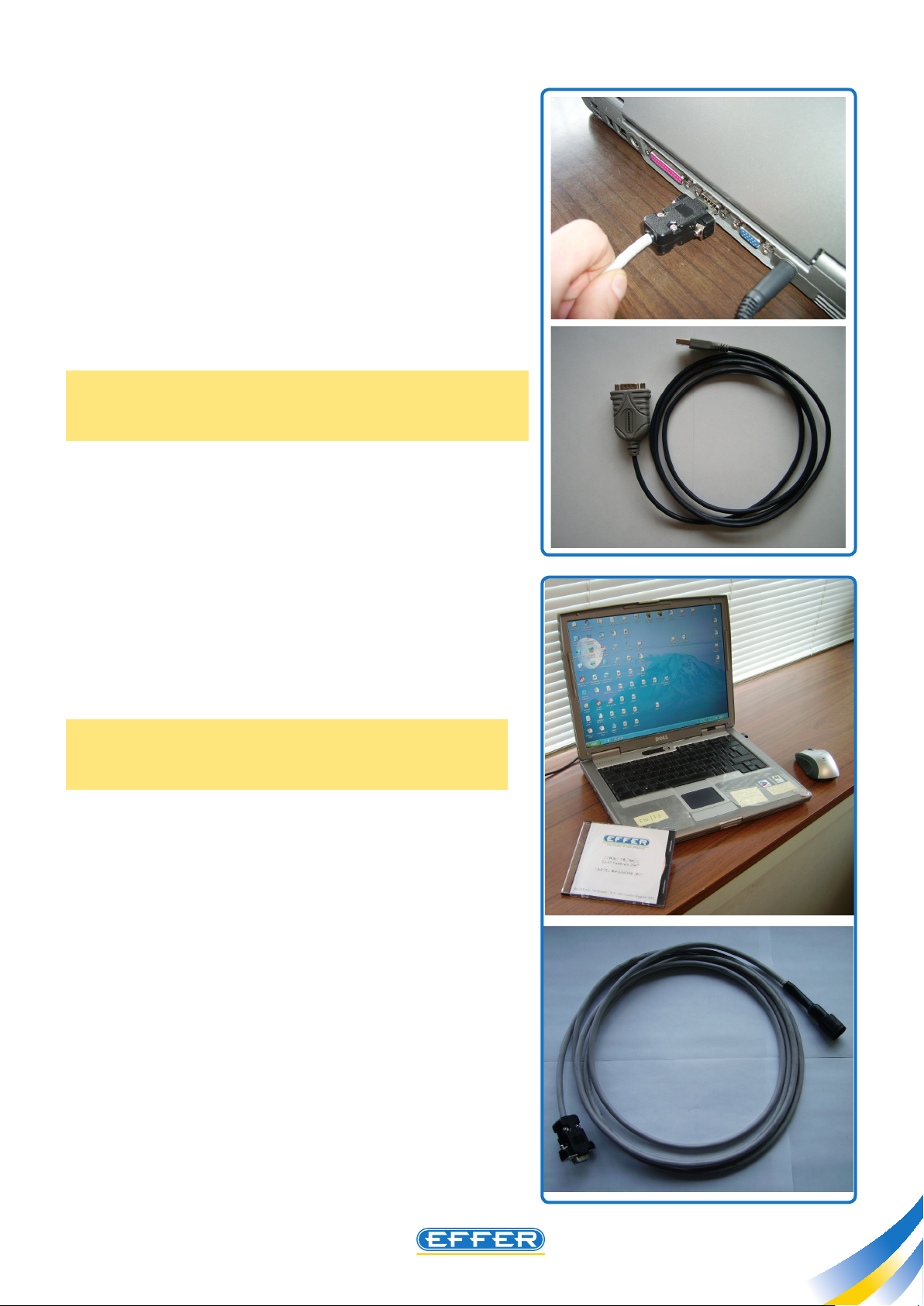
In order to change some parameters of BMS2 device, you will
need the following equipment:
1) Personal computer running windows 98 or higher, tted
with a com* communication port.
*If your personal computer does not have a com communication port, Eer has a USB adapter which we tested (Eer code
9395922)
NOTE: Not all adpters for USB port are right for this kind
of communication.
C4.2
2) BMS2 software, supplied by EFFER on CD-ROM.
This software (Eer Code CD_BMS2_1.0) can be used both
on cranes equipped with Danfoss control bank and on cranes
equipped with Hawe control bank.
3) Connection cable between the computer and the radio
control receiving unit (Eer code 9396060)
45
Page 46

THE POWER OF PERFORMANCE
Radio controls - HETRONIC BMS2
Radio controls - HETRONIC BMS2
C4.2
Instructions for software use
SOFTWARE START-UP
A) Connect the connecting cable to the computer and the radio control receiver, then operate the crane
electrically.
B) Start up the computer.
Insert the CD into computer.
46
 Loading...