

Page 1

User’s Manual
MFSHL-BMTX
Transmitter
Page 2

1. DESCRIPTION
The MFSHL-BMTX is a transmitter/coder with an RF section that uses a Binary FSK Modulation
with a frequency of 915MHz, 76800 Baud rate and 3% Duty Cycle.
The coder also works in cable control mode. When the coder detects a cable connection, no signal is
given to the RF section. Instead, a CAN output is given to the cable.
Note: Operation is subject to the following two conditions: (1) this device may not
cause interference, and (2) this device must accept any interference that may cause
undesired operation of the device.
2. TECHNICAL SPECIFICATIONS
Temperature Range -20o to +70o Celsius
Supply Voltage Range 2-5 VDC
Supply Current 42mA max
28mA for 5 seconds on startup
Outputs RF-Data
2 LED
Inputs 24 digital
RF Specifications
Frequency 915.0 MHz
Modulation Binary FSK
Deviation 64KHz
Output Power 5dBm
Note: The user is cautioned that changes or modifications not expressly approved by the
party responsible for compliance could void the user’s authority to operate the
equipment.
Page 3
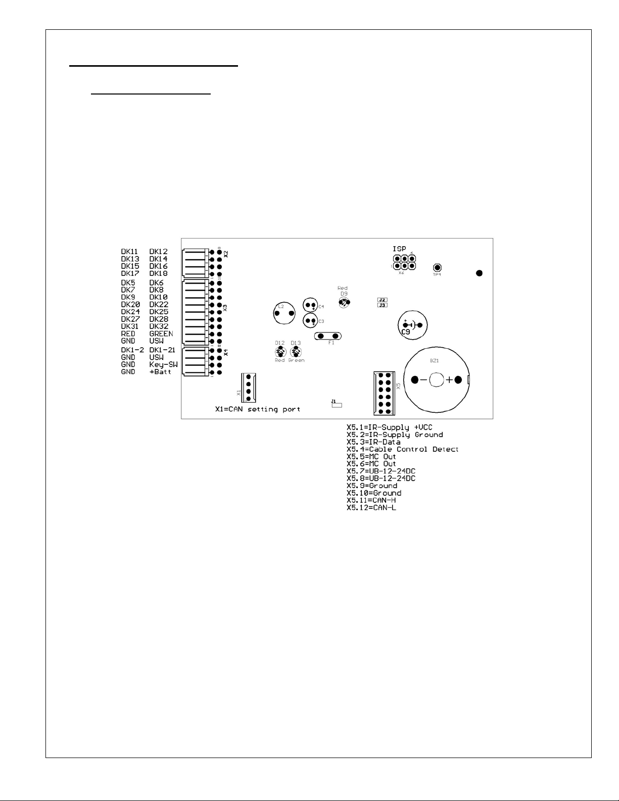
3. FUNCTIONAL DESCRIPTION
3.1. Transmitter Operation
• The MFSHL-BMTX is capable of transmitting 24 DKs including DK32 and DK31. When E-Stop is
activated, all DKs are OFF except for DK31.
• During Cable mode, when the main contact turns ON, CAN output will be activated.
• The DK1 can be used to reset the receiver from main contact error.
MFSHL-BMTX Connection Description
Page 4
3.2. LED Description
3.2.1. CAN LEDs
Red LED
o Flashing –CAN power is on.
o Solid – CAN is connected to a CAN bus
Green LED
o Flashing – Valid telegram transmitted
3.2.2. System LEDs
Green LED
o Flashing – Transmission of telegram on RF
o On – Transmission of telegram in cable mode
Red LED
o Flashing – Transmission of telegram when battery is low.
o Flashing (alternate with Green) – Main contact error
Yellow LED
o Flashing – System is running (watch dog LED)
Green, Red, & Yellow
o Flashing at Startup – System is working
3.3. Buzzer Description
• 2 short beeps at Startup – System is working.
• Short beep every 5 seconds – Low Voltage Warning.
• Regular beeping – Battery failure.
3.4. Low Voltage Indicator
The Low Voltage Indicator has two levels of detection. The first is a pre warning that triggers when the
battery is at 3.5V. At this time, the buzzer will begin to give a short beep every 5 seconds, and the LED
will start blinking RED. When the battery voltage reaches 3.4 volts the buzzer will begin beeping
regularly. After 30 seconds the transmitter will send two seconds of E-Stop telegrams and then turn off.
Power must be cycled to turn on the unit again.
3.5. Test Mode
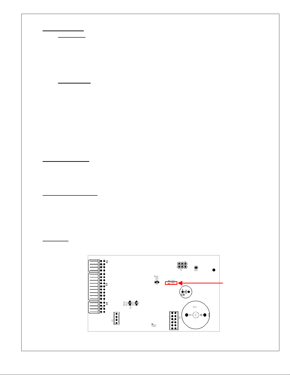
Short Jumper J3 to continuously transmit RF signal for testing.
Short J3 for
Test mode
 Loading...