

Page 1
Page 2

Model 8000 Computron
LIMITED WARRANTY FOR HENNY PENNY APPLIANCES
Subject to the following conditions, Henny Penny Corporation makes the following limited warranties to the
original purchaser only for Henny Penny appliances and replacement parts:
NEW EQUIPMENT: Any part of a new appliance, except lamps and fuses, which proves to be
defective in material or workmanship within two (2) years from date of original installation, will be
repaired or replaced without charge F.O.B. factory, Eaton, Ohio, or F.O.B. authorized distributor. To
validate this warranty, the registration card for the appliance must be mailed to Henny Penny within ten
(10) days after installation.
REPLACEMENT PARTS: Any appliance replacement part, except lamps and fuses, which proves to
be defective in material or workmanship within ninety (90) days from date of original installation will be
repaired or replaced without charge F.O.B. factory, Eaton, Ohio, or F.O.B. authorized distributor.
The warranty for new equipment and replacement parts covers only the repair or replacement of the defective
part and does not include any labor charges for the removal and installation of any parts, travel or other expenses
incidental to the repair or replacement of a part.
EXTENDED FRYPOT WARRANTY: Henny Penny will replace any frypot that fails due to manufacturing or
workmanship issues for a period of up to seven (7) years from date of manufacture. This warranty shall not cover
any frypot that fails due to any misuse or abuse, such as heating of the frypot without shortening.
0 TO 3 YEARS: During this time, any frypot that fails due to manufacturing or workmanship
issues will be replaced at no charge for parts, labor, or freight. Henny Penny will either install a
new frypot at no cost or provide a new or reconditioned replacement fryer at no cost.
3 TO 7 YEARS: During this time, any frypot that fails due to manufacturing or workmanship
issues will be replaced at no charge for the frypot only. Any freight charges and labor costs to
install the new frypot as well as the cost of any other parts replaced, such as insulation,
temperature probes, high limits, fittings, and hardware, will be the responsibility of the owner.
Any claim must be presented to either Henny Penny or the distributor from whom the appliance was
purchased. No allowance will be granted for repairs made by anyone else without Henny Penny’s
written consent. If damage occurs during shipping, notify the sender at once so that a claim may be
filed.
THE ABOVE LIMITED WARRANTY SETS FORTH THE SOLE REMEDY AGAINST HENNY PENNY
FOR ANY BREACH OF WARRANTY OR OTHER TERM. BUYER AGREES THAT NO OTHER REMEDY
(INCLUDING CLAIMS FOR ANY INCIDENTAL OR CONSQUENTIAL DAMAGES) SHALL BE
AVAILABLE.
The above limited warranty does not apply (a) to damage resulting from accident, alteration, misuse, or abuse;
(b) if the equipment’s serial number is removed or defaced; or (c) for lamps and fuses. THE ABOVE LIMITED
WARRANTY IS EXPRESSLY IN LIEU OF ALL OTHER WARRANTIES, EXPRESS OR IMPLIED,
INCLUDING MERCHANTABILITY AND FITNESS, AND ALL OTHER WARRANTIES ARE EXCLUDED.
HENNY PENNY NEITHER ASSUMES NOR AUTHORIZES ANY PERSON TO ASSUME FOR IT ANY
OTHER OBLIGATION OR LIABILITY.
FM01-909
Page 3

Model 8000 Computron
TABLE OF CONTENTS
Section Page
Section 1. OPERATION ................................................................................................................... 1-1
1-1. Introduction ............................................................................................................ 1-1
1-2. Operating Controls ................................................................................................. 1-1
1-3. Clock Set ................................................................................................................ 1-4
1-4. Basic Operations and Procedures ........................................................................... 1-6
1-5. Clean-Out Mode..................................................................................................... 1-9
Section 2. PROGRAMMING .......................................................................................................... 2-1
2-1. Introduction ............................................................................................................ 2-1
2-2. Product Program Mode ..........................................................................................2-1
2-3. Special Program Mode........................................................................................... 2-8
2-4. Data Logging, Heat Control, Tech Mode, and Stat Mode...................................... 2-16
2-5. Program Settings Worksheets ................................................................................2-16
Section 3 ERROR CODES
3-1. Introduction ............................................................................................................ 3-1
3-2. Error Codes Table ..................................................................................................3-1
Section 4 INFORMATION MODE
4-1. Information Mode Functions.................................................................................. 4-1
Section 5 PARTS INFORMATION & WIRING DIAGRAMS
5-1. Introduction ............................................................................................................ 5-1
5-2. Genuine Parts .........................................................................................................5-1
5-3. How to Order.......................................................................................................... 5-1
5-4. Prices......................................................................................................................5-1
5-5. Delivery.................................................................................................................. 5-1
5-6. Warranty................................................................................................................. 5-1
Wiring Diagrams.................................................................................................... 5-4
Distributor Lists - Domestic and International
ii 902
Page 4

Model 8000 Computron
SECTION 1. OPERATION
1-1. INTRODUCTION This section provides basic operating procedures for the
Henny Penny Computron 8000 fryer. See fryer Operator
Manual for more details on fryer operation.
1-2. SAFETY The only way to insure safe operation of the Henny Penny
Computron 8000 fryer is to fully understand the proper
installation, operation and maintenance procedures, found in
the fryer Operator’s Manual. The instructions in this manual
have been prepared to aid you in learning the controls.
Where information is of particular importance or is safety
related, the words NOTICE, CAUTION, or WARNING are
used. Their usage is described below:
SAFETY ALERT SYMBOL is used with DANGER,
WARNING, or CAUTION which indicates a personal
injury type hazard.
NOTICE is used to highlight especially important
information.
CAUTION used without the safety alert symbol
indicates a potentially hazardous situation
which, if not avoided, may result in property damage.
CAUTION indicates a potentially hazardous
situation which, if not avoided, may result in
minor or moderate injury.
WARNING indicates a potentially hazardous
situation which, if not avoided, could result in
death or serious injury.
DANGER INDICATES AN IMMINENTLY
HAZARDOUS SITUATION WHICH, IF NOT
AVOIDED, WILL RESULT IN DEATH OR
SERIOUS INJURY.
103 1-1
Page 5
Model 8000 Computron
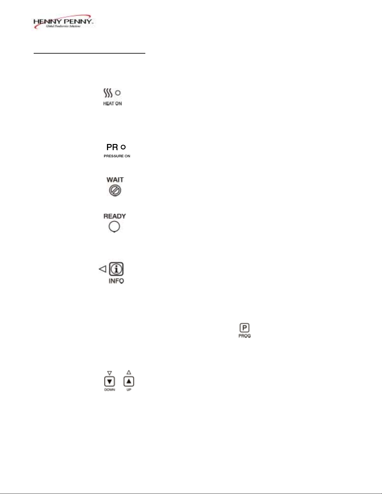
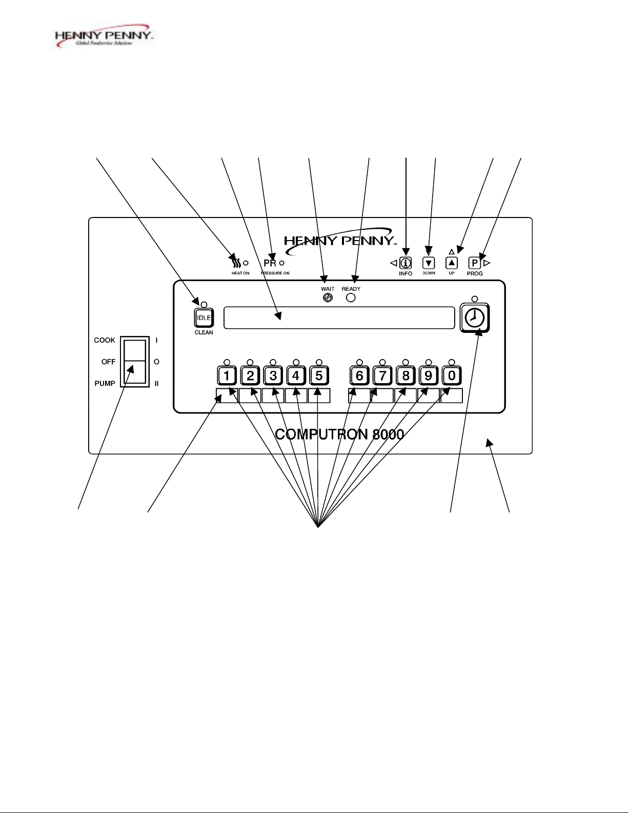
1-3. OPERATING CONTROLS Refer to Figure 1-1.
Fig. Item Description Function
No. No.
1-1 1 Lights when the control calls for heat. The elements or
burners come on and heat the shortening.
1-1 2 Digital Display Shows all the functions of the cook cycle, program modes,
diagnostic modes, and alarms.
1-1 3 Lights when the solenoid closes and pressure starts to build
inside frypot.
1-1 4 Flashes when the shortening temperature is NOT at the
proper temperature for cooking product.
1-1 5 Lights when the shortening temperature is 5° F below to
15° F above the cooking temperature, signaling the operator
that the shortening temperature IS at the proper temperature
for cooking product.
1-1 6 Press to display the following fryer information and status:
a. The temperature of the shortening
b. The temperature setpoint
c. The number of cook cycles until Filter Lockout
d. Date and Time
If pressed in the Program Mode, shows previous settings.
Pressing this along with accesses the Information
Mode which has historic information on the operator and
fryer’s performance.
1-1 7 & 8 Used to adjust the value of the currently displayed setting in
the Program modes.
1-2 103
Page 6
Model 8000 Computron
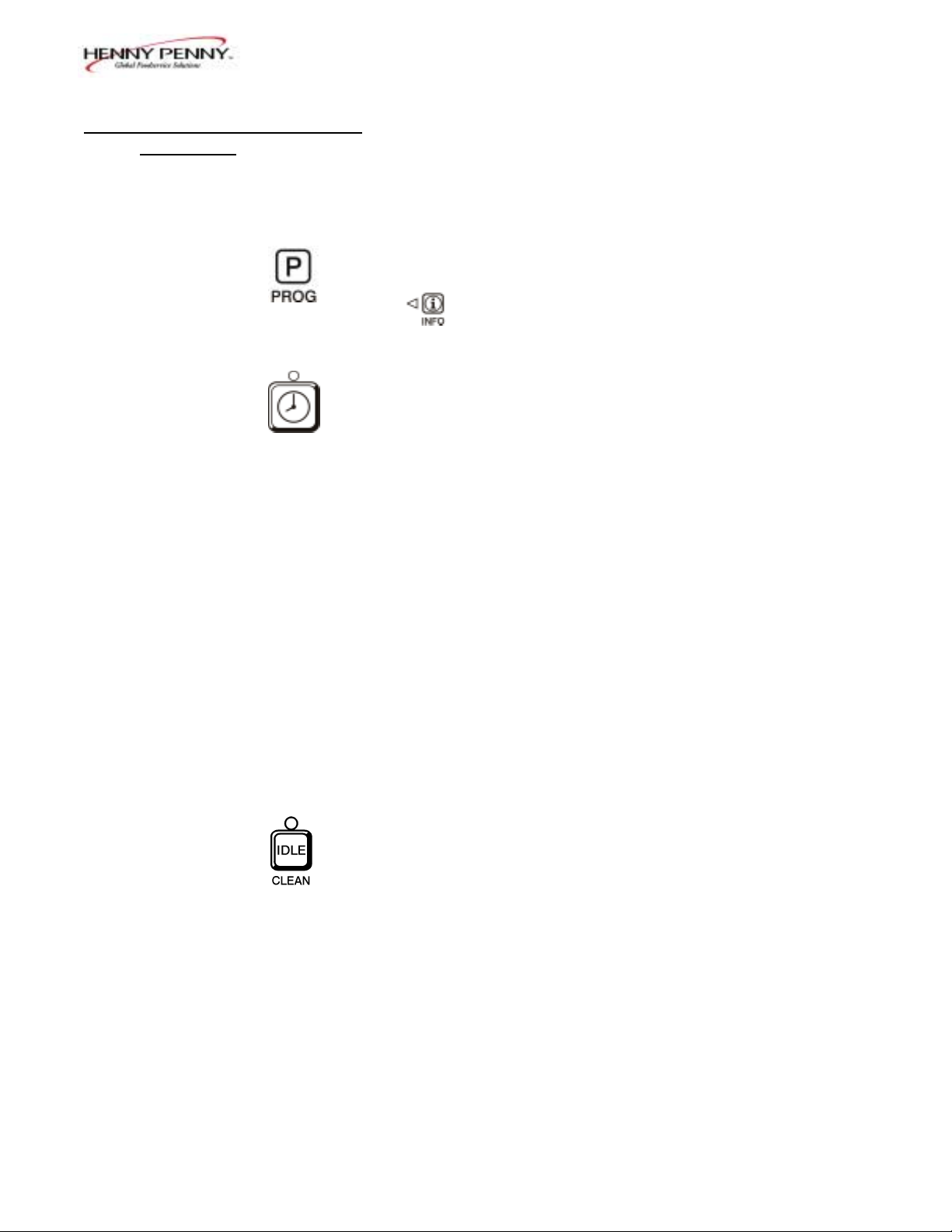
1-3. OPERATING CONTROLS
(Continued)
Fig. Item Description Function
No. No.
1-1 9 Press to access program modes. Once in the program mode, it
is used to advance to the next setting. If pressed along with
it accesses the Information Mode which has historic
information on the operator and fryer’s performance.
1-1 10 Used to start and stop cook cycles, and to stop the timer at
the end of a holding cycle.
1-1 11 Menu Card The name of the food product associated with each Product
Window Selection button. The menu card strip is located behind the
decal.
1-1 12 Product Select Are used to select the product for cooking.
Buttons To use them to start cook cycles, see section 3, Special
Program Mode item SP-10.
1-1 13 Cook/Pump Switch A 3-way switch with a center OFF position. Turn the switch
to the Cook position to operate the fryer. Turn the switch to
the Pump position to operate the filter pump. Certain
conditions must be met before operating the filter pump.
These conditions are covered later in the Filtering Section of
the fryer manual.
1-1 14 Used to manually enter an Idle Mode, or Clean-out Mode.
103 1-3
Page 7
Model 8000 Computron
14 1 2 3 4 5 6 7 8 9
13 11 10 15
12
Figure. 1-1
1-4 103
Page 8
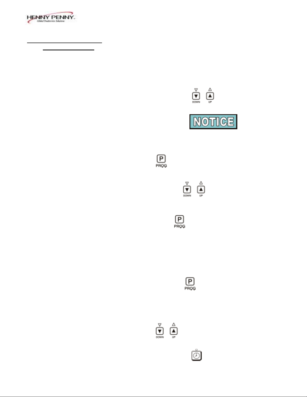
1-4. CLOCK SET
Upon initial start-up, or PC board replacement, if
“CLOCK SET” automatically appears in the display,
start with step 4.
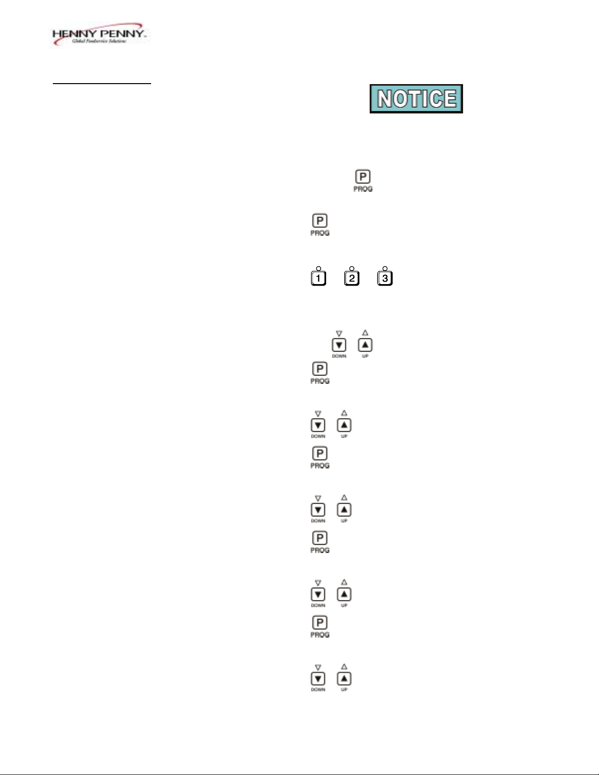
1. Press and hold for 5 seconds until “LEVEL 2”
shows in display.
2. Press and “CLOCK SET”, “ENTER CODE”
shows in display.
3. Press . .
4. “CS-1, SET, MONTH”, and the month flashes in the
display.
Model 8000 Computron
5. Press the to change the month.
6. Press and “CS-2, SET, DATE” shows in the
display, with the date flashing.
7. Press to change the date.
8. Press and “CS-3, SET, YEAR” shows in the
display, along with the year flashing.
9. Press to change the year.
10. Press and “CS-4, SET, HOUR” shows in the
display, with the hour and “AM” or “PM” flashing.
11. Press to change the hour and AM/PM setting.
12. Press and “CS-5, SET, MINUTE” shows in the
display, with the minutes flashing.
13. Press to change the minutes.
103 1-5
Page 9

Model 8000 Computron
1-4. CLOCK SET 14. Press and “CS-6, CLOCK MODE” shows in the
(Continued)
display, along with “1.AM/PM”.
“1.AM/PM” is 12 hour time, “2.24-HR” is 24 hour
time. Press to change.
15. Press and “CS-7, DAYLIGHT SAVINGS ADJ”
shows in the display, along with “2.US”.
Press to change to the following:
a. “1.OFF” = No automatic adjustments for Daylight
Savings Time.
b. “2.US” = Automatically applies United States
Daylight Savings Time adjustment. DST activated
on the first Sunday in April. DST de-activated on
the last Sunday in October.
c. “3.EURO” = Automatically applies European (CE)
Daylight Saving Time adjustment. DST activated
on the last Sunday in March. DST de-activated on
the last Sunday in October.
16. Press and “CS-8, BEGIN NEW DAY” shows in
display, along with “3:00AM”.
This setting indicates the time of day that statistics start
accumulating for a new day. If set to 3:00AM, for
example, then late night cook cycles and filter
operations from midnight to 3:00AM Tuesday morning,
are accumulated with Monday's statistics.
The CS-8 value can be set from 12:00AM (midnight) to
8:00AM, in half hour increments (12:00 AM,
12:30 AM, 1:00 AM, 1:30 AM, etc.). The default value
for general market software is 3:00 AM.
Press to change the time the “new” day starts.
17. Clock Set is now complete. Press and hold to exit.
1-6 103
Page 10
Model 8000 Computron
1-5. BASIC OPERATIONS These are just basic procedures. Refer to the Operator’s
AND PROCEDURES 500/600/561 manual for more detailed instructions.
1. Be sure the drain valve is in the closed position.
2. Remove fry basket from frypot and leave lid up.
3. Fill the frypot with shortening.
When using new shortening, it is recommended to melt
the shortening on an outside source before placing
shortening in the frypot. Unless elements are
completely covered in shortening, fire or damage to the
frypot could result.
4. Move power switch to the "COOK" position. Unit
automatically goes into the melt cycle. When the
temperature reaches 230°F (110°C) the control goes
into the heat cycle, and heats the shortening until the
temperature setting is reached.
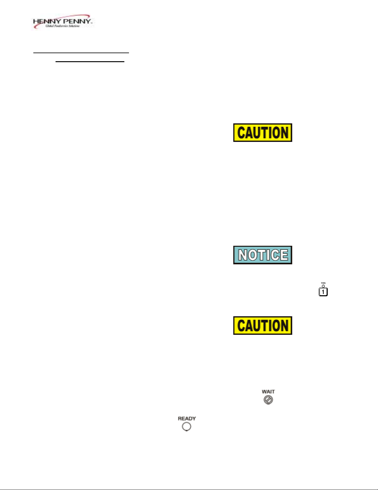
Bypass the melt cycle, if desired, by pressing a Product
button and holding it for five seconds. The display
shows “EXIT MELT? 1=YES 2=NO”. Press
to exit melt.
Do not bypass the melt cycle unless enough shortening
has melted to completely cover all of the heating
elements, or the curved surface of the gas frypot. If melt
cycle is bypassed before these surfaces are covered,
excessive smoking of the shortening or a fire will result.
5. Once out of the Melt cycle, flashes until
5° before setpoint temperature is reached. Then
illuminates and the selected product shows
in the display.
103 1-7
Page 11
Model 8000 Computron
1-5. BASIC OPERATIONS 6. Completely stir shortening to stabilize the temperature
AND PROCEDURES throughout the frypot.
(Continued)
7. Once the shortening temperature has stabilized at the
setpoint temperature, place the baskets into the
shortening. Then place product into the basket.
Do not overload, or place product with extreme
moisture content into the basket. 18 lbs. (8.2 kgs.)
for the 561 and 12 lbs. (5.4 kgs.) for the 500 and 600,
is the maximum amount of product per frypot.
Failure to follow these directions can result in
shortening overflowing the frypot. Serious burns or
damage to the frypot could result.
8. Lift the basket slightly out of the shortening and shake
basket to separate pieces.
9. Remove basket handle and close lid quickly, latching
the lid.
10. Tighten the lid spindle clockwise, sealing the lid. Align
red knob on the spindle with red knob on the latch.
LATCH THE LID PROPERLY AND ALIGN THE
RED BALLS OR SEVERE BURNS WILL
RESULT.
11. Press to start a cook cycle.
The display counts down the cooking time.
A different product can be selected during the first
minute of cooking, in case the wrong Product Button
was pressed. To check the shortening temperature
press or to stop a cook cycle, press .
1-8 103
Page 12

Model 8000 Computron
1-5. BASIC OPERATIONS 12. Within a few minutes, the pressure gauge increases to
AND PROCEDURES the OPERATING ZONE. If not, recheck the install-
(Continued) ation and operation procedures in Operator’s Manual.
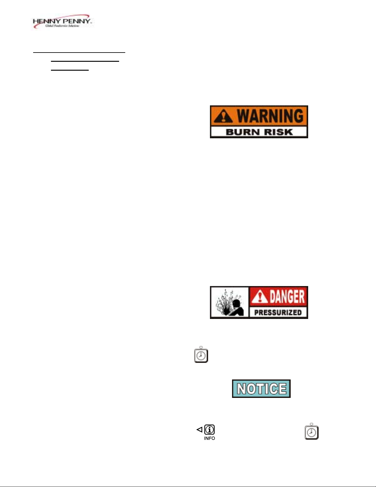
13. Near the end of the cook cycle the fryer automatically
depressurizes, an alarm sounds and the display flashes
“DONE”. To stop the alarm, press .
DO NOT ATTEMPT TO OPEN LID UNTIL THE
PRESSURE DROPS TO ZERO. LID IS LOCKED
WHEN FRYER IS UNDER PRESSURE. DO NOT
ATTEMPT TO FORCE THE LID LATCH OR
OPEN THE LID WHILE UNDER PRESSURE.
OPENING THE LID WHEN THE FRYPOT IS
PRESSURIZED ALLOWS HOT SHORTENING
AND STEAM TO ESCAPE FROM THE FRYPOT,
RESULTING IN SEVERE BURNS.
14. After pressure drops to zero, turn the spindle counterclockwise.
Do not flip or spin the spindle cross arm when opening
the lid because it could damage the acme nut inside the
cross bar.
15. Unlatch and raise the lid quickly to allow most of the
condensation on the lid to drain through the drain
channel and not into the shortening.
Do not let the lid slam up against the backstop
because damage to the hinge could result.
16. Using the detachable handle, lift the basket and inspect
product for doneness. Dump product into holding pan.
17. If a Quality time (hold time) was programmed, the
controller automatically starts the hold timer. The
display alternately shows the product selected and the
quality time remaining in minutes. If a different
product is selected during the hold cycle, the display
only shows the product selected.
103 1-9
Page 13

Model 8000 Computron
1-5. BASIC OPERATIONS 18. At the end of the Hold mode, a tone sounds, the
AND PROCEDURES display flashes “QUALITY”, and the product it was
(Continued) timing. Press and release .
In the Cook mode, when "FILTER SUGGESTED”,
shows in the display, the operator has the option to
filter at this time, or to continue cooking. But, if the
operator continues cooking, a Filter Lockout occurs
within the next cook cycle, or two.
When "FILTER LOCKOUT" , then "YOU *MUST*
FILTER NOW........” shows in the display, is the only
button that functions, until the unit is filtered. Follow the
steps in the 500/600/561 Service manual on filtering.
1-6. CLEAN-OUT MODE The Computron 8000 has a Clean-Out Mode to clean the
frypot upon initial start-up and every change of shortening.
Follow the steps in the 500/600/561 Service manual on
Cleaning the Frypot.
When heating the cleaning solution and vinegar solutions,
turn the Cook/Pump switch to “COOK. ” When the fryer
starts the Melt Cycle, press and hold then
“CLEAN-OUT ?”, “1=YES 2=NO”shows in display. Press
to start Clean-Out mode. The fryer displays
“*CLEAN-OUT MODE*” and heats up to a preprogrammed
temperature, then automatically begins a preset timed
countdown. Use the UP and DOWN buttons, if necessary, to
adjust the temperature and keep the cleaning solution from
boiling over.
See Special Program Modes SP-10 and SP-11
to preset the temperature and time.
1-10 103
Page 14

1-6. CLEAN-OUT MODE
Continued)
NEVER PRESSURIZE FRYER TO CLEAN. LEAVE
THE LID OPEN. WATER UNDER PRESSURE IS
SUPER HEATED AND CAUSES SEVERE BURNS IF
IT COMES IN CONTACT WITH SKIN.
If the cleaning solution in the frypot starts to foam
and boil over, immediately turn the Cook/Pump
Switch to OFF and do not try to contain it by closing
the fryer lid or severe burns could result.
Model 8000 Computron
103 1-11
Page 15

Model 8000 Computron
SECTION 2. PROGRAMMING
2-1. INTRODUCTION The controls are preset from the factory, but desired functions
can be programmed in the field. This section includes the
Product Programming Mode, which are the basic settings,
and the Level 2 programming, which are the more detailed
settings.
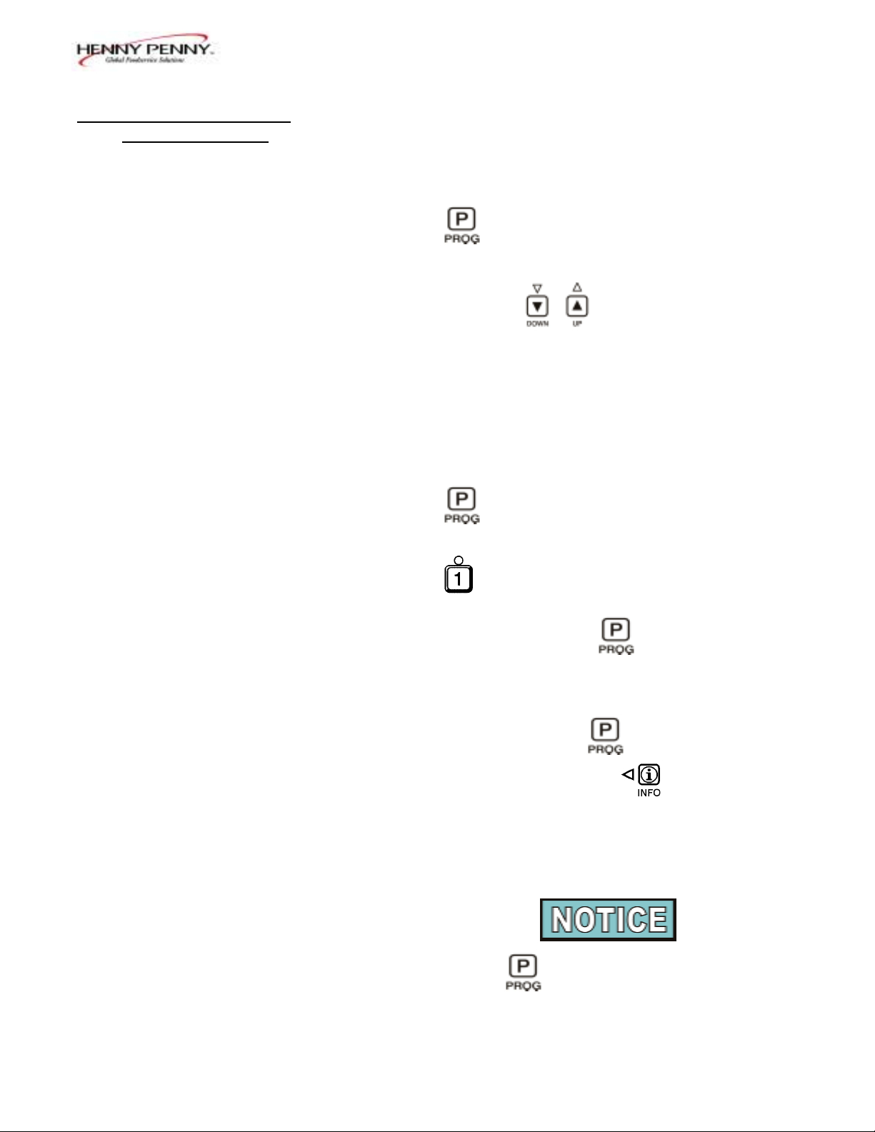
2-2. PRODUCT PROGRAM This mode allows the operator to change and set various
MODE parameters for each product.
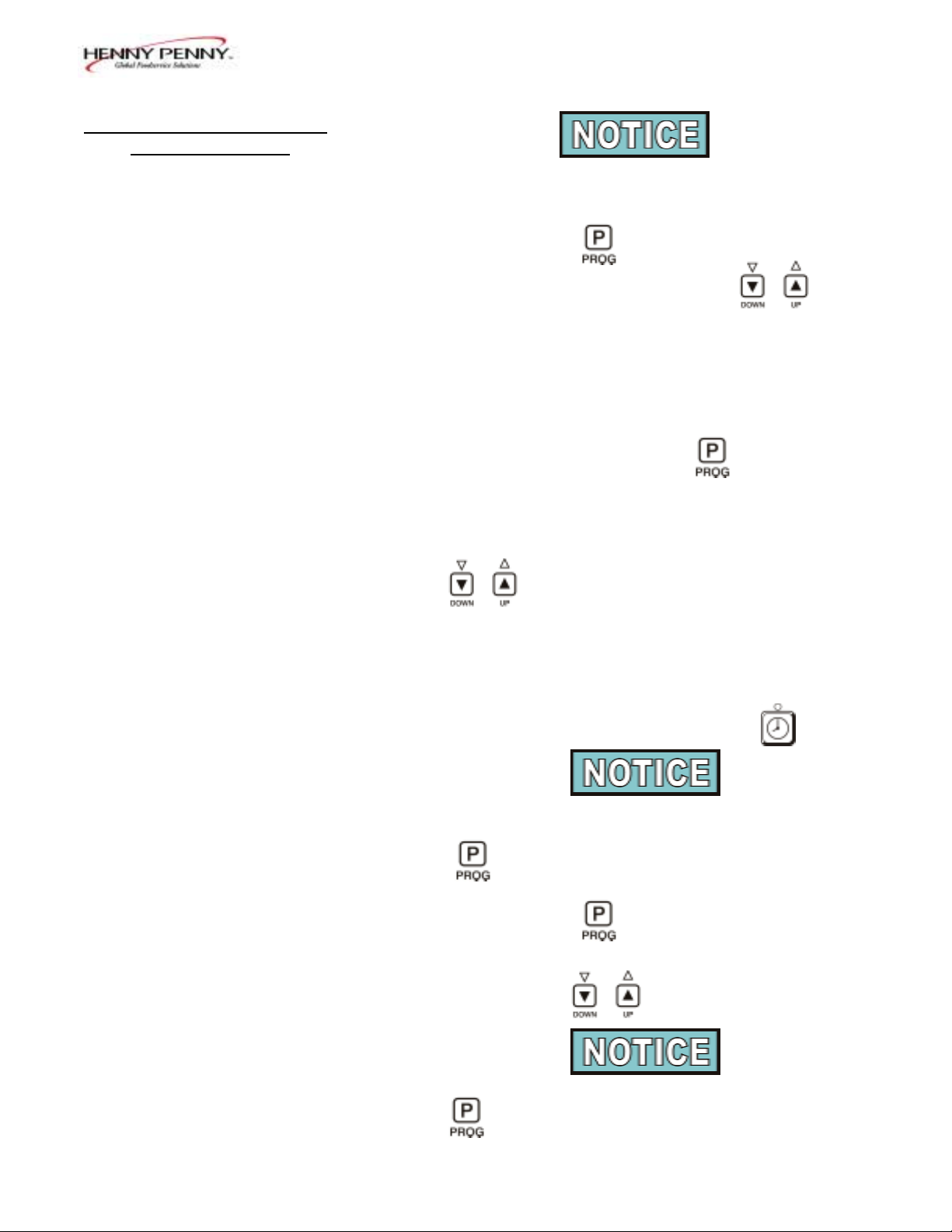
1. Press and hold for one second until
“PROG” shows in the display, followed by
“ENTER CODE”.
2. Enter code 1, 2, 3. "SELECT PRODUCT…PRESS
PROG” scrolls across the display.
3. Press and release the desired Product button (1 to 10).
Press to copy a product, erase a product, preset a
product, erase all products, or preset all products.
4. Press and release . The name of that product
shows in the display. Ex. “ NAME“FRIES”.
Change Product Names
a. Press and release and the first letter, or digit,
starts flashing.
b. Press and release to change the flashing letter.
c. To continue to the next letter, press . Then press
to change this letter.
d. Repeat step c until up to 7 letters are entered.
103 2-1
Page 16

Model 8000 Computron
2-2. PRODUCT PROGRAM e. Press and hold to exit Program Mode, or press and
MODE (Continued)
release until “PRELOAD” shows in display, to
continue with Program Mode.
5. The Preload Mode allows the operator to drop large
pieces first, with the lid up, before loading the rest of
the product. The preload cycle always runs without
pressure and which always regulates to the Step 1
cook temperature. Press to set a Preload
time, or press if no Preload is desired
6. Press and release and "1. COOK TIME" shows in
the display along with the preset time. Press
to change the time. The time shows in
minutes and seconds. Press and hold the buttons, and
the time will jump by 5 second increments to a
maximum of 59:59.
7. Press and release and "1. TEMP" shows in the
display, along with the preset temperature on the right
side of the display. Press to change the
temperature. Press and hold the buttons and the
temperature will jump by 5 degree increments to a
max. of 380°F (193ºC), and a min. of 190°F (88ºC).
8. Press and release and 1. PRESSURE” shows
“in the display along with “YES” or “NO”. Press
to build pressure in the first step, or not.
9. Press and release and “2. STEP 2 AT” shows in
display, along with a step 2 time. If no step 2 is desired,
set time to “0:00” and press . If a step 2 is
desired, press and set a time. Then press
to set temperature and pressure.
2-2 702
Page 17
2-2. PRODUCT PROGRAM
MODE (Continued)
Up to 10 steps can be programmed for a product,
repeating the above step for each cooking step.
10. Press and release and “ALARM – 1 AT 0:00”
shows in the display. Press and release
to set an alarm. Ex: If a cook cycle was set at 3
minutes, and an alarm was to go off after 30 seconds
into the cook cycle, “2:30” would be set in the display
at this time. When the timer counts down to 2:30 the
alarm sounds.
After the alarm time is set, press and “ALARM”
Model 8000 Computron
and “TYPE” flashes in the display, with the alarm type
on the right side of the display. “TIME”, “SHAKE”,
“STIR”, “ADD”, and “LID” can be set by pressing
. An alarm sounds and alarm type flashes,
prompting the operator to shake the basket, stir the
product, or add product. If “TIME” is selected, the time
remaining flashed in the display. If “LID” is selected,
“CLOSE LID” flashes in the display. The timer countdown is paused until the lid is closed and m is
pressed to restart the timer.
Up to 4 alarms can be programmed. After the first one is
set, the other alarms can be accessed by pressing
butt again.
11. Press and release until "QUALITY TMR" shows
in the display along with the preset holding time. Press
and release the to adjust the holding time,
up to 59:59.
To exit the Program Mode at any time, press and hold
for 2 seconds.
103 2-3
Page 18
Model 8000 Computron
2-2. PRODUCT PROGRAM 12. Press and release and “LOAD COMP" shows in
MODE (Continued)
the display along with the load compensation value.
This automatically adjusts the time to account for the
size and temperature of the cooking load. Press and
release to change this value to a max. of 20
and a min. of 0. Preset at factory at 5.
13. Press and release and "LCOMP REF" shows in
the display along with the load compensation average
temperature. This is your average cooking temperature
for the products you cook. The timer speeds up at
temperature above this setting and slows down at
temperatures below this setting. Press and release
to change this value.
Or, to use the cooking setpoint temperature as the load
compensation reference point, press until “STEP-X”
and “TEMP” flashes in the display. Now for example,
if the cooking temperature is 350°, the timer speeds up
when the shortening temperature is above 350, and
slows down when the temperature is below 350.
14. Go to Idle after Done?
Press and release and "GO TO IDLE, AFTER
DONE" shows in the display, along with “YES” or
“NO”. Press to toggle between YES and NO.
15. Filter Cycle Mode (Optional)
For "FILTER AFTER" to appear in the Product
Program Mode, the Filter Tracking must be enabled in
the Special Program Mode. (See section 4-3.) You
have the option to program “mixed” (each product has
its own filter count) or “global” (all products have the
same count).
Press .
2-4 602
Page 19
Model 8000 Computron
2-2. PRODUCT PROGRAM “2,Mixed”
MODE (Continued) a. "FILTER AFTER" shows in the display, along with
the preset number of cook cycles.
b. Press and release until the desired number of
cook cycles between filters shows in the display. For
example, if 4 is set for a product, each time that product is
selected, it counts 1/4, or 25%. Then each time a product
is cooked, the percentages add up until 100%, or more is
reached. Then display shows "FILTER SUGGESTED".
"3,GLOBAL"
a. "FILTER INCL" shows in the display, along with "NO"
or "YES"
b. Press and release to "YES" if that product is
to be included in the filter count, or "NO" if it is not.
Copy/Erase Pre-set Products
Products and their setpoints can be copied from one menu
location on the controller to another location, preset the
controls to factory settings, or erase products and all their
values.
1. Press and hold for one second until
“PROG” shows in the display, followed by
“ENTER CODE”.
2. Enter code 1, 2, 3. "SELECT PRODUCT…PRESS
PROG” scrolls across the display, followed by
“DOWN” FOR OPTIONS”
3. Press and “**OPTION**”, followed by
“*1. COPY A PROD” shows in display. Press
again, each time, to view the following options:
*1. COPY A PROD
*2. ERASE A PROD
*3. PRESET A PROD
*4. ERASE ALL
*5. PRESET ALL
103 2-5
Page 20

Model 8000 Computron
2-2. PRODUCT PROGRAM 4. To select one of the above options, press while the
MODE (Continued) desired option shows in display.
Selecting PRESET A PROD, or PRESET ALL PROD
sets factory setpoints in those menu items.
Press at any time to exit the Options menu, or
wait 30 seconds and controller automatically exits.
The following are examples of copying and erasing products:
Copying
Press to select the presently displayed "COPY A
PROD" option. “COPY __ TO __” shows in display
The first set of "_" is blinking. Select the product you wish
to copy from, for example, by pressing the button:
“COPY 2 TO __” shows in display.
Next, press product you want to copy to, for example, by
pressing the button. The controller responds with a
confirmation message:
“COPY 2 TO 0?”
“1=YES 2=NO”
Press (YES) and the controller copies product #2 to the
product #0 position (the #2 product is left intact) and the
display shows “* COPIED *”, then returns to the "Select
Prog Product" step with the #0 product already selected.
Press (NO), or don't press any button for 20 seconds,
the controller displays "X CANCELED X" and abandons the
copy process. In this case no changes are made
.
Erasing
On the "Select Prog Product" step, press :
“** OPTIONS **” followed by “*1. COPY A PROD” shows
in display.
2-6 702
Page 21

Model 8000 Computron
2-2. PRODUCT PROGRAM Press three more times to reach the "Erase All" option:
MODE (Continued)
“*2. ERASE A PROD”
“*3. PRESET A PROD”
“*4. ERASE ALL”
Press to select the presently displayed "Erase All"
option. The controller responds with a confirmation
message:
“ERASE ALL PROD ?”
“1=YES 2=NO”
Press (YES) to confirm that you want to erase all
products back to "empty" values. The controller responds by
erasing each product individually...
“ERASING 1”
“ERASING 2”
“ERASING 3”
“ERASING 4”
“ERASING 5”
“ERASING 6”
“ERASING 7”
“ERASING 8”
“ERASING 9”
“ERASING 0”
Then briefly displays “* ALL ERASED *” and finally,
returns to the "Select Prog Product" display.
602 2-7
Page 22

Model 8000 Computron
2-3. SPECIAL PROGRAM The Special Program mode is used to set more detailed
MODE parameters listed below.
SP-1 • Degrees Fahrenheit or Celsius
SP-2 • Language: English, French, German,
Spanish, and Portuguese
SP-3 • System Initialization
SP-4 • Audio Volume
SP-5 • Audio Tone
SP-6 • Type of Shortening to be Melted - Liquid, Solid
SP-7 • Idle Mode
SP-8 • Filter Tracking
SP-9 • Product Buttons
SP-10 • Clean-Out Minutes
SP-11 • Clean-Out Temperature
SP-12 • Nominal Amps Reading
SP-13 • Amps Reading Low Limit (percentage)
SP-14 • Amps Reading High Limit (percentage)
SP-15 • Program Code Change
1. Press and hold for 5 seconds until
"L-2" and "LEVEL 2", followed by, “SP PROG" and
“ENTER CODE shows in the display.
2. Enter code 1, 2, 3, and "SP- 1 ", "TEMP, UNITS"
shows in the display.
If a bad code is entered, an alarm sounds and "BAD
CODE" shows on the display. Wait a few seconds,
the control reverts back to the cook mode, and
repeat the above steps.
To exit from the Special Program mode at any time, press
and hold button for 2 seconds, or to roll back to
previous setting, press .
Degrees Fahrenheit or Celsius (SP-1)
a. Follow steps 1 and 2 above.
b. The display flashes "SP- 1" and "TEMP, UNITS", along
with "ºF" or "ºC". Press
buttons to toggle from "ºF" to "ºC", or vice versa.
2-8 103
Page 23
2-3. SPECIAL PROGRAM Language (SP-2)
MODE (Continued) a. Follow steps 1 and 2 above.
b. Press and release button. "SP-2" and
"LANGUAGE" flashes on the display, along with the
language (Ex:" 1.ENGL")
c. To toggle to the desired language, press and release
.
System Initialization (SP-3)
This step resets the controls, but doesn’t erase product
settings.
a. Follow steps 1and 2 above.
Model 8000 Computron
b. Press and release twice. "SP-3" and "DO
SYSTEM INIT" flashes on the display, along with
"INIT'.
c. Press and hold . "INIT" shows on the display,
a tone sounds, and "IN 3”, “IN 2”, “ IN 1” flashes on the
right side of the display. When "INIT" starts flashing on
the left side of the display, release . When “ DONE”
shows on the display, the initialization is complete, and
the controls now have factory preset parameters.
Audio Volume (SP-4)
The volume of the speaker can be adjusted.
a. Follow steps 1 and 2 above.
b. Press the 3 times. "SP-4" and
"AUDIO VOLUME" flashes on the display, along
with the volume value.
c. Press to adjust the speaker volume; 10
the maximum value and 1 the minimum.
103 2-9
Page 24

2-3. SPECIAL PROGRAM Audio Tone (SP-5)
MODE (Continued) The tone of the speaker can be adjusted.
a. Follow steps 1 and 2 above.
b. Press 4 times. "SP-5" and "AUDIO TONE (HZ)"
flashes on the display, along with the tone value.
c. Press to adjust the tone of the
speaker; 2000 the maximum, 50 the minimum.
Type of shortening to be melted - Liquid or Solid (SP-6)
The Melt cycle can be set to the type of shortening being
used.
a. Follow steps 1 and 2 above.
b. Press and release 5 times. "SP-6"
Model 8000 Computron
and "MELT CYCLE SELECT" flashes on the display,
along with "l=LIQ" or "2=SOLID".
c. Press to toggle from one type to another.
The type of shortening being used in the fryer
determines the amount of heat applied during the
Melt cycle. If the controls are set to the Solid
setting, less heat is applied to the shortening, than if
the controls were set to Liquid. Too much heat
applied to solid shortening causes much smoking,
and could cause a fire. Match this setting to the type
of shortening being used at the time.
When using new shortening, it is recommended to melt
the shortening on an outside source before placing
shortening in the frypot. Unless elements are
completely covered in shortening, fire or damage to the
frypot could result.
2-10 103
Page 25

Model 8000 Computron
2-3. SPECIAL PROGRAM Idle Mode (SP-7)
MODE(Continued) A programmed Idle mode allows the shortening temperature
to drop to a lower temperature when not in use. This saves
on the shortening and utilities.
a. Follow steps 1and 2 above.
b. Press and release 6 times. "SP-7" and "IDLE
MODE ENABLED?" flashes in the display, along with
"NO" or "YES".
c. Press and release to toggle from NO to YES,
or vice versa.
d. With "YES" in the display, the Idle mode is enabled.
Press and release . "SP-7A" and
"IDLE SETPT TEMP" shows in the display, along with
the preset temperature.
e. Change the Idle setpoint temperature, by pressing
f. Press and release . "SP-7B" and
"AUTO-IDLE MINUTES" shows in the display, along
with the preset time.
g. Press to set the minutes the fryer stays idle
before the Auto-idle is enabled; 60 the maximum, OFF
the minimum. Ex: "30" in the display means, if product
is not cooked in that frypot for 30 minutes, the control
automatically activates the idle setpoint temperature,
programmed above.
h. Press and release . "SP-7C" and “GO IDLE AT
MELT ?” shows in display.
i. Press to toggle from NO to YES, or vice versa.
With "YES" in the display, the fryer automatically enters
the Idle Mode once the Melt Mode is exited.
602 2-11
Page 26
Model 8000 Computron
2-3. SPECIAL PROGRAM Filter Tracking Enabled (Sp-8)
MODE (Continued) The controls can be set to signal the operator when the
shortening needs filtering. The Filter Tracking must be
enabled to program the number of cook cycles between
filtering procedures. (See Filter Cycles section 2-2.)
a. Follow steps 1 and 2 above.
b. Press and release until "SP-8"
and "FILTER TRACKING ENABLED" flashes on the
display, along with "1,OFF".
c. To enable the filter tracking, press
to toggle the display from "1,OFF", to
"2,MIXED", or, "3,GLOBAL".
The Mixed setting allows the operator to set different
amounts of cook cycles, between filters, for each
product. If the operator wants to have one setting for
all products go to step h.
d. If "2,MIXED" is selected, press and
“SP-8A” shows in the display followed by
“SUGGEST FILTER AT …” and a value between 75%
and 100%. Press and release the
to change this value.
e. Press and “SP-8B” shows in the display followed
by “LOCKOUT ENABLED?” and “YES” or “NO”.
Press and release to choose yes or no.
f. Press and “SP-8C” shows in the display, if YES
was chosen in step e. FILTER LOCKOUT AT…” and a
value between 100% and 200% shows in display. Press
to change this value.
2-12 103
Page 27
Model 8000 Computron
2-3. SPECIAL PROGRAM g. Now, go back to the Product Program mode, to the
MODE (Continued) Filter Cycle, and program in the number of cook cycles
between filtering.
h. If "3,GLOBAL" is selected, "SP-8A" shows in the
display, and followed by "GLOBAL FILTER
CYCLES". The right side of the display shows a
digit, 1 to 99. Press to set the desired
amount of cook cycles between filters.
In cook mode, the number of global cook cycles
remaining shows in the center of the display.
Ex: "-------- 5x ---------".
i. Press and “SP-8B” shows in the display followed
by “LOCKOUT ENABLED?” and “YES” or “NO”.
Press and release to choose yes or no.
j. Now, go back to section 2-2 and enter the Program
mode. Press until "FILTER INCL" shows in
the display (step 13). Each product must be set to
"YES" to be included in the filter tracking.
Product Buttons (Sp-9)
This mode allows you set up the way products are selected,
and cook cycles started, in the cook mode.
a. Follow steps 1 and 2 above.
b. Press and release until “SP-9” and
“PRODUCT BUTTONS” flashes in the display.
c. When using the first option, “1,COOK”, pressing a
Product button displays that product and starts the cook
cycle. When nothing is cooking, no product displays.
d. Press . to show the second option. If using
"2,SELECT", pressing a Product button displays the
product only. Press to start the cook cycle.
103 2-13
Page 28

Model 8000 Computron
2-3. SPECIAL PROGRAM Clean-Out Temperature (Sp-10)
MODE (Continued) This allows you to set the number of minutes of the Clean-
Out Mode.
a. Follow steps 1 and 2 above.
b. Press until “SP-10” and “CLEAN-OUT
MINUTES” shows in display, along with the preset
minutes.
c. Press to change the number of minutes, up to
99.
Clean-Out Temperature (Sp-11)
This allows you to set the temperature of the Clean-Out
Mode.
a. Follow steps 1 and 2 above.
b. Press until “SP-11” and “CLEAN-OUT
TNP” shows in display, along with the set temperature.
c. Press to change the temperature, up to
212ºF (100ºC).
Nominal Amps Reading (SP-12)
a. Press until “SP-12”, “AMPS RDG,
NOMINAL” shows in display.
b. Check the amp reading on the right side of display
(ex: “37 A”) with the amp reading on the data
plate. If readings are different, use to
change display to match data plate.
(This could vary depending upon how the unit is wired.)
Amps Reading Low Limit (SP-13)
This is the percentage below the Nominal Amp Reading in
which the controls senses a too low amperage warning (E27).
Preset at 80%, but can be changed (50 to 99%):
a. Follows steps 1 and 2 above.
b. Press until "SP-13" and "AMPS RDG, LOW
LIMIT" shows in the display, along with the preset
percentage.
c. Press to change percentage.
2-14 602
Page 29
Model 8000 Computron
2-3. SPECIAL PROGRAM Amps Reading High Limit (SP-14)
MODE (Continued) This is the percentage above the Nominal Amp Reading in
which the controls senses a too high amperage warning (E25).
Preset at 110%, but can be changed (101 to 150%):
a. Follows steps 1 and 2 above.
b. Press until "SP-14" and "AMPS RDG, HIGH
LIMIT" shows in display, along with the preset
percentage.
c. Press and release to change percentage.
Program Code Change (SP-15)
This allows the operator to change the program code (factory
set at 1, 2, 3) used to access Product Programming, Special
Programming, Clock Set, Data Comm, and Heat Control
modes.
a. Follows steps 1 and 2 above.
b. Press until "SP-15" and "CHANGE, MGR CODE,
1=YES” shows in display, along with “CODE”.
c. Press . “ENTER NEW CODE, P=DONE, I=QUIT”
shows in display. Press Product buttons with new code.
d. If satisfied with code, press . “REPEAT NEW
CODE, P=DONE, I=QUIT, shows in display. Press same
code buttons in step c.
e. If satisfied with code, press . “*CODE CHANGE*”
shows in display.
f. If not satisfied with code, press and
*CANCELLED* shows in display, then reverts back to
"SP-15" and "CHANGE, MGR CODE, 1=YES”. Then
the above steps can be repeated.
Press and hold at any time to exit Special Program
Mode.
103 2-15
Page 30

Model 8000 Computron
2-4. DATA LOGGING, HEAT The Data Logging, Heat Control, Tech and Stat Modes are
CONTROL, TECH MODE, advanced diagnostic and program modes, mainly for
AND STAT MODE Henny Penny use only. For more information on these
Modes, contact the Service Department at
1-800-417- 8405, or 1-937-456-8405.
2-5. PROGRAM SETTINGS The next two pages are worksheets for your convenience.
WORKSHEETS They may be helpful in determining and recording setpoints.
2-16 103
Page 31
Model 8000 Computron
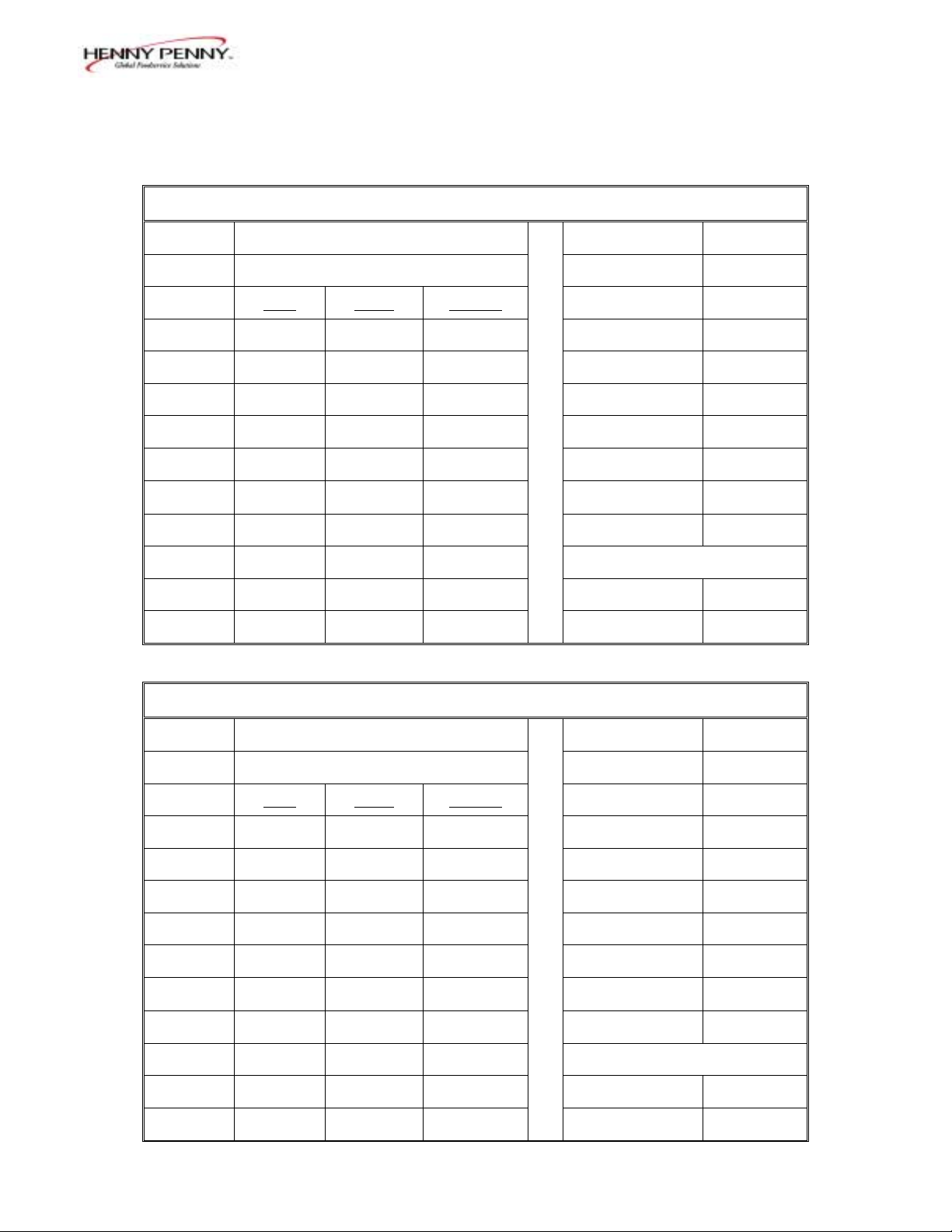
Henny Penny Computron 8000 Customer_________________
Product Settings Worksheet Date_________________
Button # Product Description:
Name:
PreLoad:
Step 1
Step 2
Step 3
Step 4
Step 5
Step 6
Step 7
Step 8
Step 9
Step 10
_ _ _ _ _ _ _ (7 Characters Max)
(Always uses Step 1 Temp.)
Time Temp. Pressure
YES NO
YES NO
YES NO
YES NO
YES NO
YES NO
YES NO
YES NO
YES NO
YES NO
Alarm-1
Alarm-2
Alarm-3
Alarm-4
Quality Timer
Load Comp
LComp Ref.
Go To Idle
when done?
-- Optional Filter settings --
Only one (or neither one) appears
Filter After...
Filter Include?
YES NO
YES NO
902 2-17
Page 32
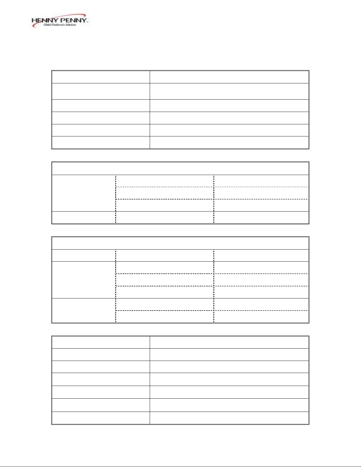
Henny Penny Computron 8000 Customer_________________
SP PROG Settings Worksheet Date_________________
Model 8000 Computron
SP-1 Temperature Units
SP-2 Language
SP-3 Initialize Step
SP-4 Audio Volume
SP-5 Audio Tone (Hz)
SP-6 Melt Cycle Select
°F °C
1.English 2. Français 3. Deutsch 4. Español 5. Portuguese
(English) (French) (German) (Spanish) (Portuguese)
xxxxxxxxxxxxxxxxxxxxxxxxxxxxxxxxxxxxxxxxxxxxxxxxxxx
1 2 3 4 5 6 7 8 9 10
(Frequency, 50 - 2000 Hz)
1. SOLID 2. LIQUID
SP-7 Idle Mode Enabled? (Select YES or NO below and complete corresponding section)
SP-7A Idle Setpoint Temp
YES
SP-7B Auto-Idle Minutes
SP-7C Go to Idle at Melt Exit?
YES NO
NO xxxxxxxxxxxxxxxxxxxxxxxxxxxxx xxxxxxxxxxxxxxxxxxxxxxxxxxxxxx
SP-8 Filter Tacking Mode (Select 1, 2, or 3 below and complete corresponding section)
1. OFF xxxxxxxxxxxxxxxxxxxxxxxxxxxxx xxxxxxxxxxxxxxxxxxxxxxxxxxxxxx
SP-8A Suggest Filter At...
2. MIXED
SP-8B Lockout Enabled?
SP-8C Filter Lockout At...
SP-8A Global Filter Cycles
3. GLOBAL
SP-8B Lockout Enabled?
SP-9 Product Buttons
SP-10 Clean-out Minutes
SP-11 Clean-out Temperature
SP-12 Nominal Amps Reading
SP-13 Amps Reading Low Limit
SP-14 Amps Reading High Limit
SP-15 Manager's Access Code
YES NO
YES NO
1. COOK 2. SELECT
Normal, expected current draw.
("OFF" for Gas fryers.)
Acceptable range below normal.
Acceptable range above normal
("OFF" for Gas fryers.)
("OFF" for Gas fryers.
)
2-18 902
Page 33

Model 8000 Computron
SECTION 3. ERROR CODES
3-1. INTRODUCTION This section provides error codes and their
information in the form of an easy-to-read table.
If a problem occurs during the first operation of a
new fryer, recheck the installation section of the
500/600/561 Operator’s manual.
3-2. ERROR CODE TABLE In the event of a control system failure, the digital
display shows an error message. These messages
are coded: “E4”, “E5”, “E6”, “E10”, “E15”, “E25”,
“E26”, “E27”, “E41”, “E46”, “E47”, “E48”,
“E70A” & “B” and “E920”. An alarm sounds
when an error code is displayed, and to silence this
alarm, press any button.
DISPLAY CAUSE PANEL BOARD CORRECTION
“E4” Control Board Turn switch to OFF position, then turn switch back to ON.
Overheating If display shows E4, the control board is getting too hot.
Check the louvers on each side of the unit for obstructions.
Check cooling fan, if present.
“E5” Shortening Turn switch to OFF position, then turn switch back to ON.
Overheating If display shows E5, the heating circuits and temperature
probe should be checked.
“E6-A” Temperature Turn switch to OFF position, then turn switch back to ON.
Probe Open If display shows E6, have the temperature probe checked.
“E6-B” Temperature Turn switch to OFF position, then turn switch back to ON.
Probe Shorted If display shows E6 have the temperature probe checked.
“E10” High Limit Reset the high limit by manually pushing up on the reset
button. If high limit does not reset, high limit must be
replaced.
“E15” Drain Switch Close drain, using the drain valve handle. If display still
Failure shows E-15, have the drain microswitch checked.
“E25” Heat Amps Have electrical supply, wiring and elements checked
Too High
103 3-1
Page 34

Model 8000 Computron
3-2. ERROR CODE TABLE
(Continued)
DISPLAY CAUSE PANEL BOARD CORRECTION
“E26” Heat Amps Have the contactors and PC board checked.
Locked On
This error code could be displayed even with the Power
switch turned OFF. Unplug fryer or shut off the wall
circuit breaker to disconnect power to the fryer.
“E27” Heat Amps Have electrical supply, contactors, wiring and elements
Too Low checked.
“E41”, “E46” Programming Turn switch to OFF, then back to ON. If display shows any
Failure of the error codes, try to reinitialize the control (Section
4-3). If error code persists, replace the control board per
section 6-11.
“E47” Analog Converter Turn switch to OFF, then back to ON. If E47 persists,
Chip or 12 Volt have the I/O board, or the PC board replaced. If speaker
Supply Failure tones are quiet, probably I/O board failure.
“E48” Input System Have PC board replaced.
Error
“E-70-A” Missing or broken Have jumper wire between pins 1 and 2 checked.
wire in pins 1 and
2 of P11 connector,
or faulty connector.
Faulty I/O board. Have I/O board checked and replaced if necessary.
Open interlock on Have fan, extinguisher switch, side panel switches, and air
PVS units. pressure switch circuits checked.
“E70-B” Faulty Power Have Power switch checked, along with its wiring. Have
Switch, or switch Input/Output board replaced if necessary.
wiring. Faulty
I/O board.
“E-92” 24 VAC Fuse 24 VAC fuse on I/O Board open. Check for shorted
on I/O board open component in 24-volt circuit. (I.E., hi limit, drain switch)
3-2 103
Page 35

Model 8000 Computron
SECTION 4. INFORMATION MODE
4-1. INFORMATION MODE This mode gathers and stores historic information on the
FUNCTIONS fryer and Operator’s performance. Press and
at the same time and “*INFO MODE*” shows on display.
Press or to access the steps and press to
view the statistics within each step. Info Mode is intended
for technical use, but the operator can view the following
information:
1. E-LOG - last 10 errors and time they occurred
2. LAST LOAD - information about the most recent cook
cycle, or the cycle presently in progress
3. DAILY STATS - information for the last 7 days.
4. REVIEW USAGE- information accumulated since the
last time this data was manually reset.
5. INP A VHDSF M - provides test of fryer inputs
6. OUTP - shows the state of heater and pressure
7. OIL TMP - temperature of shortening
8. CPU TMP - temperature of PC board
9. ANALOG - status of controller’s a-to-d converter
10. AMPS - the present amp readings to heaters.
Press and hold to exit Information Mode at
any time, or after 2 minutes, controls automatically exit
back to normal operation.
1. E-LOG (error code log)
Press and “1A. (date & time) *NOW*” shows in
display. This is the present date and time.
Press and if a error was recorded, “1B. (date, time, and
error code information)” shows in display. This is the latest
error code that the controls recorded.
103 4-1
Page 36
Model 8000 Computron
4-1. INFORMATION MODE Press and the next latest error code information can be
FUNCTIONS (Continued)
seen. Up to 10 error codes (1B to 1K) can be stored in the
E-LOG section.
Press to continue to LAST LOAD.
2. LAST LOAD
Press to view the following information from the most
recent cook cycle.
FUNCTION DISPLAY EX:
Time of day the last cook cycle was started
Product (Last product cooked)
Ready? (Was fryer Ready before start?)
Stopped: Time remaining, or secs past Done
Actual Elapsed Cook Time (real seconds)
Programmed Cook Time
Actual Time vs. Prog Time (Percentage)
Max Temp during cook cycle
Min Temp during cook cycle
Avg Temp during cook cycle
Heat On (percentage) during cook cycle
STARTED 10.25A
PRODUCT -2READY? YES
*DONE* + 9 SECS
ACTUAL TIME 7:38
PROG TIME 7:00
ACT / PROG 109%
MAX TEMP 327°F
MIN TEMP 313°F
AVG TEMP 322°F
HEAT ON 73%
Only if Presently Cooking:
Present cook step, setpoint, and time rem.
Actual Oil Temp., Deg below Load Comp
Avg, present Stretch Time (real secs / ck sec)
Press to continue to DAILY STATS.
STEP 1:325°F 6:47
313°F LC-12° 1.06
4-2 602
Page 37

Model 8000 Computron
4-1. INFORMATION MODE 3. DAILY STATS (reset each day)
FUNCTIONS (Continued) Press to view the following operation information for any
of the last 7 days. Press to select which day.
FUNCTION DISPLAY EX:
Day this data was recorded for
Number of Hours:Minutes the fryer was on
Number of times shortening was filtered that
day
Total number of cook cycles that day
Cook Cycles for Product #1
Cook Cycles for Product #2
Cook Cycles for Product #3
Cook Cycles for Product #4
Cook Cycles for Product #5
Cook Cycles for Product #6
Cook Cycles for Product #7
Cook Cycles for Product #8
Cook Cycles for Product #9
Cook Cycles for Product #0
TUE* APR-30
TUE* ON HRS 13:45
TUE* FILTERED 3
TUE* TOTAL CK 38
TUE* COOK -1- 17
TUE* COOK -2- 9
TUE* COOK -3- 5
TUE* COOK -4- 0
TUE* COOK -5- 0
TUE* COOK -6- 6
TUE* COOK -7- 0
TUE* COOK -8- 0
TUE* COOK -9- 1
TUE* COOK -0- 0
Press to continue to REVIEW USAGE.
4. REVIEW USAGE
Press to view the accumulated information since the data
was manually reset:
FUNCTION DISPLAY EX:
Day the usage data was previously reset
Number of hours the fryer was on
Number of times shortening was filtered
Total number of cook cycles
Cook Cycles for Product #1
Cook Cycles for Product #2
Cook Cycles for Product #3
Cook Cycles for Product #4
Cook Cycles for Product #5
Cook Cycles for Product #6
Cook Cycles for Product #7
Cook Cycles for Product #8
Cook Cycles for Product #9
Cook Cycles for Product #0
Reset usage data:
Enter the Mgr Code (1, 2, 3 unless changed)
on this step to zero out all the usage
information.
SINCE APR-19
PWR ON HRS 165
FILTERED 34
TOTAL CK 462
COOKED -1- 193
COOKED -2- 107
COOKED -3- 58
COOKED -4- 0
COOKED -5- 13
COOKED -6- 69
COOKED -7- 0
COOKED -8- 7
COOKED -9- 15
COOKED -0- 0
RESET USG /
ENTER CODE ------
Press to continue to INP A_VHDSF_M.
602 4-3
Page 38

4-1. INFORMATION MODE 5. INP A_VHDSF_M
FUNCTIONS (Continued) Press to view the status of components and inputs. If the
input signal is detected, an identifying letter is displayed (see
below). If the signal is not detected, “_” is displayed.
With the Cook/Pump switch in the COOK position, and all
inputs detected, “H_ P_ A_VHDSF_M” shows in the
display. See below for “definition” of codes.
A = Power Switch in COOK position.
B = Power Switch in PUMP position
V = Volts - 24 VAC detected
H = High Limit - If “H” is present, the high limit is good.
If “H” is missing, the high limit is tripped (overheated) or
faulty.
D = DRAIN SWITCH-If “D” is present, the drain handle is
closed. If “D” is missing, the drain is open or faulty.
S = Cook/Pump switch “on” interlock circuit: If “S” is
present, the Cook/Pump switch is in the COOK position. If
the “S” is missing, the power switch is either off, failed, or
wired incorrectly.
F = FAN
P = PV – Detects 24 V jumper to PV terminal – gas fryers only
M = MV - Detects 24 V jumper to MV terminal - electric
fryers only
Model 8000 Computron
Press to view the specific status of each input. An
underscore (“_”) indicates the input is not presently detected.
A Checkmark (“√” ) indicates the signal is detecting a normal
input. A blinking (“X”) indicates the signal is presently
detected, but is detected as a half-wave (partially failed)
input.
The V, H, D, S, F, P and M signals below are wired in
series. The first signal missing out of this sequence l
generally causes all signals to the right of it to be
missing as well.
Press to continue onto OUTP H* P_.
4-4 103
Page 39

Model 8000 Computron
4-1. INFORMATION MODE 6. OUTP H* P_ (F*H*P_ for gas units)
FUNCTIONS (Continued) This mode displays the status of components and outputs. If
the output signal is detected, an identifying letter is displayed
(see below), followed by an “*”. If the output is off, “_” is
displayed.
F = Fan output (gas only)
H = Heat output
P = Pressure output
On gas units, if fan is on, “F*” shows in display. If fan is
off, “F_” shows in display. If controls senses a problem with
the fan output, “F*” shows in display, with the “*” flashing.
If heat is on, “H*” shows in display. If heat is off, “H_”
shows in display. If controls senses a problem with the heat
output, “H*” shows in display, with the “*” flashing.
If pressure is on, “P*” shows in display. If pressure is off,
“P_” shows in display. If controls senses a problem with the
pressure output, “P*” shows in display, with the “*” flashing.
Press to view the amp “DRAW” status of each output.
“F √”, “H √” and “P √” in the display means the amps are
good. A flashing “X” behind the F, H or P means too much
current.
Press to view the No Connect/Ground (“NC/GND”)
status of each output. This monitors a possible problem with
the relays on the output PC board.
“F √”, “H √” and “P √” in the display means everything on
the output PC board is good. A flashing “X” behind the F, H
or P means a problem exists.
Press to view the outputs and inputs (see step 10)
together.
Press to continue onto the OIL TMP reading.
7. OIL TMP
This step shows the present peanut oil temperature. The
display shows “7. OIL TMP (temp.)”.
Press to continue onto the CPU TMP reading.
902 4-5
Page 40

Model 8000 Computron
4-1. INFORMATION MODE 8. CPU TMP
FUNCTIONS (Continued) This step shows the present PC board temperature.
Press to continue onto the ANALOG reading.
9. ANALOG <1> 2.86V
This step displays the present status of any channel of the
controller’s a to d converter. This feature may be useful to a
technician troubleshooting a problem with the fryer or
controller.
The displayed value can be toggled between Volts and Bits
by pressing . If the displayed value has a decimal point,
it is voltage (0 to 5 VDC). If no decimal point is shown, the
value is a-to-d bits (0 - 4095).
Press to continue onto AMPS reading.
10. AMPS 33 33 33
This display shows the present readings from the fryer’s amps
sensors, which monitor the electrical current supplied to the
heaters.
These values indicate the current through each supply leg to
the heaters. These values do not necessarily correspond
directly to the current through an individual heater coil.
The “Amps” values should normally cycle on and off with
the Heat light, and all three values should be about the same.
Press and hold to exit Information Mode at any
time, or after 2 minutes, controls automatically exit
back to normal operation.
4-6 103
Page 41

Model 8000 Computron
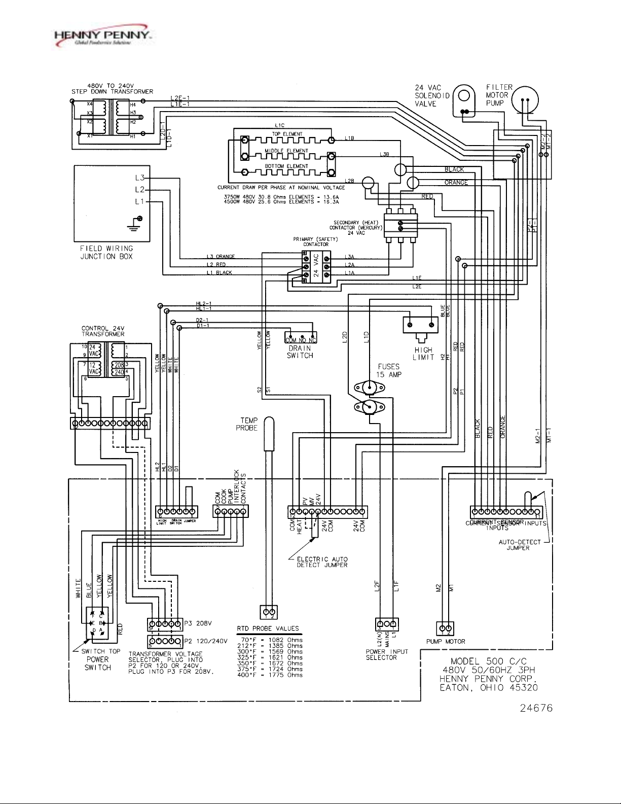
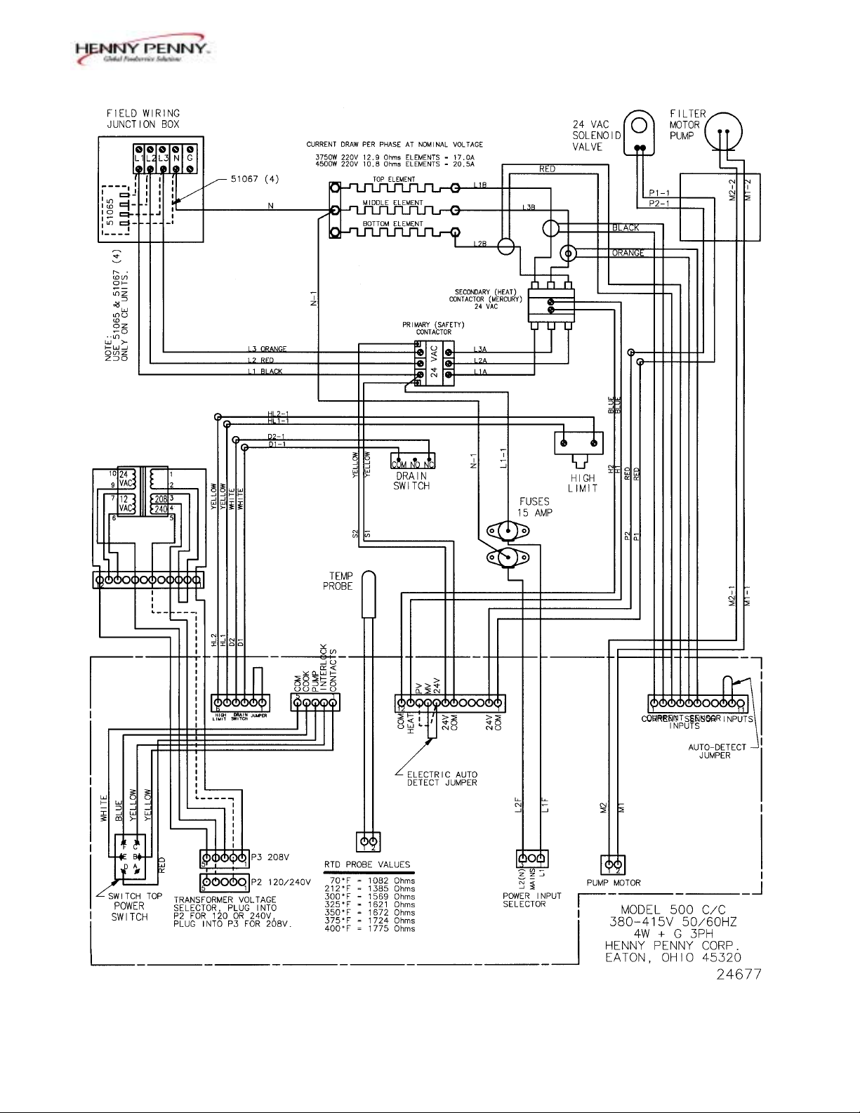
SECTION 5. PARTS INFORMATION & WIRING DIAGRAMS
5-1. INTRODUCTION This section identifies and lists the replaceable parts of the
Henny Penny Computron 8000.
5-2. GENUINE PARTS Use only genuine Henny Penny parts in your fryer.
Using a part of lesser quality or substitute design may result
in fryer damage or personal injury.
5-3. HOW TO ORDER Once the part you want to order has been found in the Parts
List, write down the following information:
1. From the Parts List
(Sample)
Item Number 13
Part Number 29898
Description Power Switch
2. From the data plate
(Sample)
Product Number PFE-500.0
Serial Number 0001
Voltage 208V
5-4. PRICES Your distributor has a price parts list and will be glad to
inform you of the cost of your parts order.
5-5. DELIVERY Commonly replaced items are stocked by your distributor
and will be sent out when your order is received. Other
parts will be ordered by your distributor from Henny Penny
Corporation. Normally, these will be sent to your
distributor within three working days.
5-6. WARRANTY All replacement parts (except lamps and fuses) are covered
under warranty for 90 days against manufacturing defects
and workmanship. If damage occurs during shipping,
notify the carrier at once so that a claim may be properly
filed. Refer to warranty on the front of this section for
other rights and limitations.
602 5-1
Page 42
Model 8000 Computron
5-2 702
Page 43

Model 8000 Computron
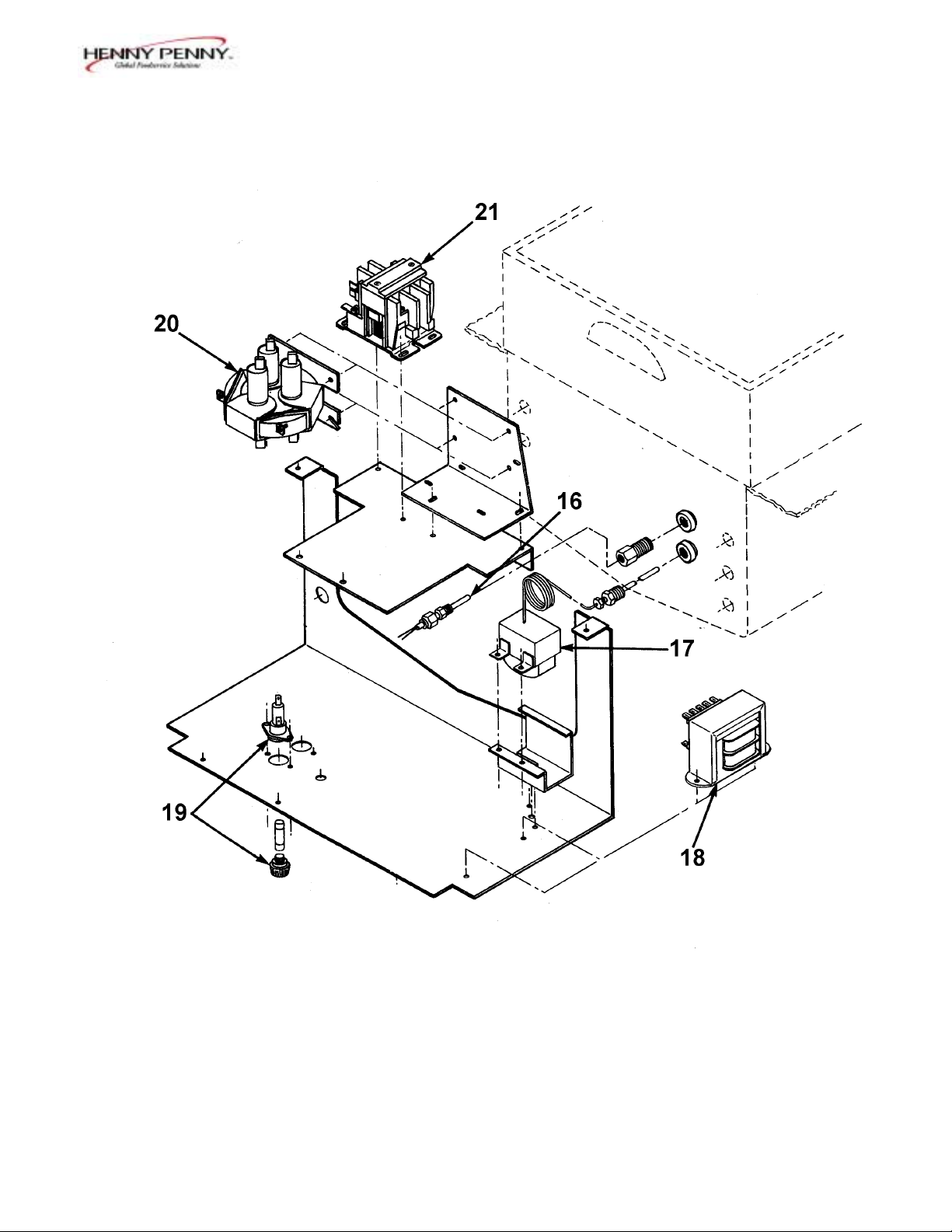
Item Part
Number Number Description Qty
(Nos. 11, 13 & 15 page 1-3)
11 32633 Card – C8000 Std. Product Menu 1
11 32634 Card – C8000 Blank Menu 1
13 29898 Power Switch 1
15 27303 Decal – Control –Bent 1
15 24849 Decal – Control – Flat 1
16 55167 Assembly – Temperature Probe/Compression Fitting 1
17 16738 High Limit – 450 degree F. 1
18 29521 Assembly – Transformer 1
19 18364 Assembly – Fuse Holder – 15 amp 2
19 EF02-007 Fuse – 15 amp 2
20 29510 Contactor – Mercury – 24 VAC 1
21 51795 Contactor – 24 VAC 1
22* 32612RB Assembly – Control 8000 Flat Panel 1
(SN: KA021JJ to GA085JB-GAS)
(SN: KB021JJ to HB013JB-ELEC.)
22* 32660RB Assembly – Control 8000 Flat Panel 1
(SN: GA086JB and above-GAS)
(SN: HB014JB and above-ELEC.)
22* 32613RB Assembly – Control 8000 Bent Panel 1
(SN: KA020JJ and below-GAS)
(SN: KB020JJ and below-ELEC.)
23* 26974 Assembly – Speaker 1
24* 29515 Solenoid – 24 Volt – 60 Hz. 1
24* 29698 Solenoid – 24 Volt – 50 Hz. 1
24* 29547 Solenoid Coil – 24 Volt – 50/60 Hz. 1
25* 63294 Insulation – Fryer Pot – ¼” 1
25* 63295 Insulation – Fryer Pot – 1/8” 1
26* 24347 Assembly – Current Sense Xformers 1
*not shown
802 5-3
Page 44
Model 8000 Computron
5-4 802
Page 45

Model 8000 Computron
702 5-5
Page 46
Model 8000 Computron
5-6 702
Page 47
Model 8000 Computron
702 5-7
Page 48
Model 8000 Computron
5-8 702
 Loading...