

559-734-7451 800-367-5480 FAX 559-734-7460
INSTALLATION INSTRUCTIONS
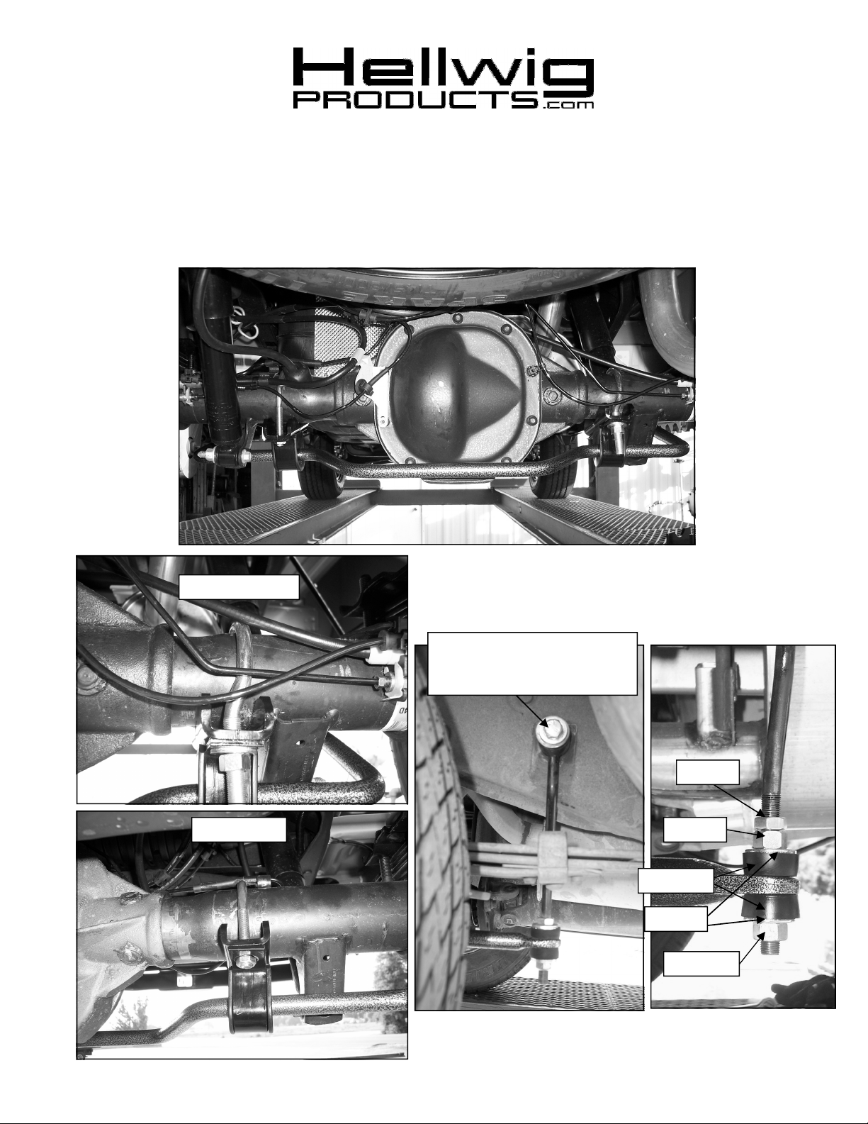
Ford Ranger Rear Stabilizer Bar
Thank you for purchasing a quality Hellwig Product.
PLEASE READ THIS INSTRUCTION SHEET COMPLETELY BEFORE STARTING YOUR INSTALLATION
Passenger Side
Driver Side
Attach end link to existing hole
in frame with 1/2” bolt and
washers
Jam Nut
1/2” Nut
Bushings
Washers
Lock Nut
R-7720 05/31/2012

ATTENTION INSTALLER: PLEASE MAKE SURE CUSTOMER RECEIVES THIS INSTRUCTION SHEET,
559-734-7451 800-367-5480 FAX 559-734-7460
TORQUE TABLE
Bolt Size 3/8”— 35 ft lbs * Bolt Size 7/16”— 45 ft lbs* Bolt Size 1/2”—75 ft lbs *Bolt Size 9/16”— 90 ft lbs
SAFETY
WHEELS.
NOTE:
BE ON THE SUSPENSION AS IF DRIVING DOWN THE ROAD. DO NOT RAISE THE VEHICLE BY THE FRAME.
: BEFORE BEGINNING INSTALLATION BE SURE TO SET THE PARKING BRAKE AND CHOCK THE
TO EASE INSTALLATION AND PROPERLY ADJUST THE BAR, THE WEIGHT OF THE VEHICLE MUST
1. Lubricate the insides of the D-bushings and place them onto the straight areas of the bar on each side of the center
hump as shown in the photos.
2. Hold bar up to the axle and locate the position on the axle tubes to mount the U-bolts. The offset U-bolt will go on
the passenger side and the straight legged U-bolt goes on the driver side as shown in the photos. Be sure to put the
U-Bolts Under Any Brake Lines, Wires or Hoses on the Axle to Avoid Any Possible Damage. It may be necessary to flex the brake lines slightly and rotate the black plastic piece on the axle breather tube. The threads of the UBolts will point down.
3. Place saddle brackets onto the U-Bolts on the axle tubes. The saddle bracket with “R” in the center goes on the passenger side with the ribs on either side of the axle where it necks down as shown in the photo. Rotate the saddle
bracket so the pad is flat.
4. Place the U-Plates over the D shaped bushings on the bar and attach the bar to the U-Bolts and saddle brackets with
the flat washers and locknuts provided. LEAVE LOOSE AT THIS TIME to allow for adjustment later.
5. Assemble end links by installing the hourglass bushing and then the spacer into the loop of the end link. Lubricate
bushing and spacer before assembly.
6. Attach end links to existing hole in frame rail using the 1/2” X 2-1/2” bolt washers and 1/2” locknut. Install bolt
through end link with a flat washer mounted to the inside of the frame rail and the outside of the bushing.
7. Assemble bushings, washers and nuts on end link as shown in photos. The lock nut installed on the bottom of the
end link bushing assembly. Adjust jam nut and hex nut on upper portion of end link to raise or lower assembly to
align arms of sway bar to be as parallel with ground as possible. On most 2WD models, it will be necessary to
tighten the jam nut all the way to the end of the threads and remove the hex nut to obtain correct alignment of the
sway bar and end link. If more height is required on 2WD models, the 4WD arrangement must be used. For most
4WD models it will be necessary to use a hex nut and jam nut on top of the end link bushing assembly to lock the
adjustment.
8. Tighten lock nut on bottom of end link until bushings begin to bulge slightly. Do not over tighten as it will damage
the bushings. If equipped, tighten jam nut against upper hex nut to lock adjustment.
8. Adjust sway bar on axle so that there is at least 1/2” clearance between the bar and the axle. Ensure adequate clearance between the sway bar and all shock absorbers, brake lines, hoses, cables and electrical connections. When all
clearances are confirmed, tighten U-bolts to 35 ft-lb.
9. Bounce vehicle and check for clearance on all undercarriage components. Recheck installation, look for clearance
on gas lines, exhaust pipes, brake lines, wiring, etc.
10. Drive vehicle for a few miles, then recheck for position and tightness, adjust and retorque as needed. Then recheck
periodically thereafter.
ALL IMPORTANT NOTE CARDS, WARNING CARDS AND THE WARRANTY FORM
R-7720 05/31/2012
 Loading...