

Hellwig 7628 User Manual
559-734-7451 800-367-5480 FAX 559-734-7460
INSTALLATION INSTRUCTIONS
Rear Stabilizer Bar
Toyota Tacoma 4x4; Pre-Runner
Thank you for purchasing a quality Hellwig Product.
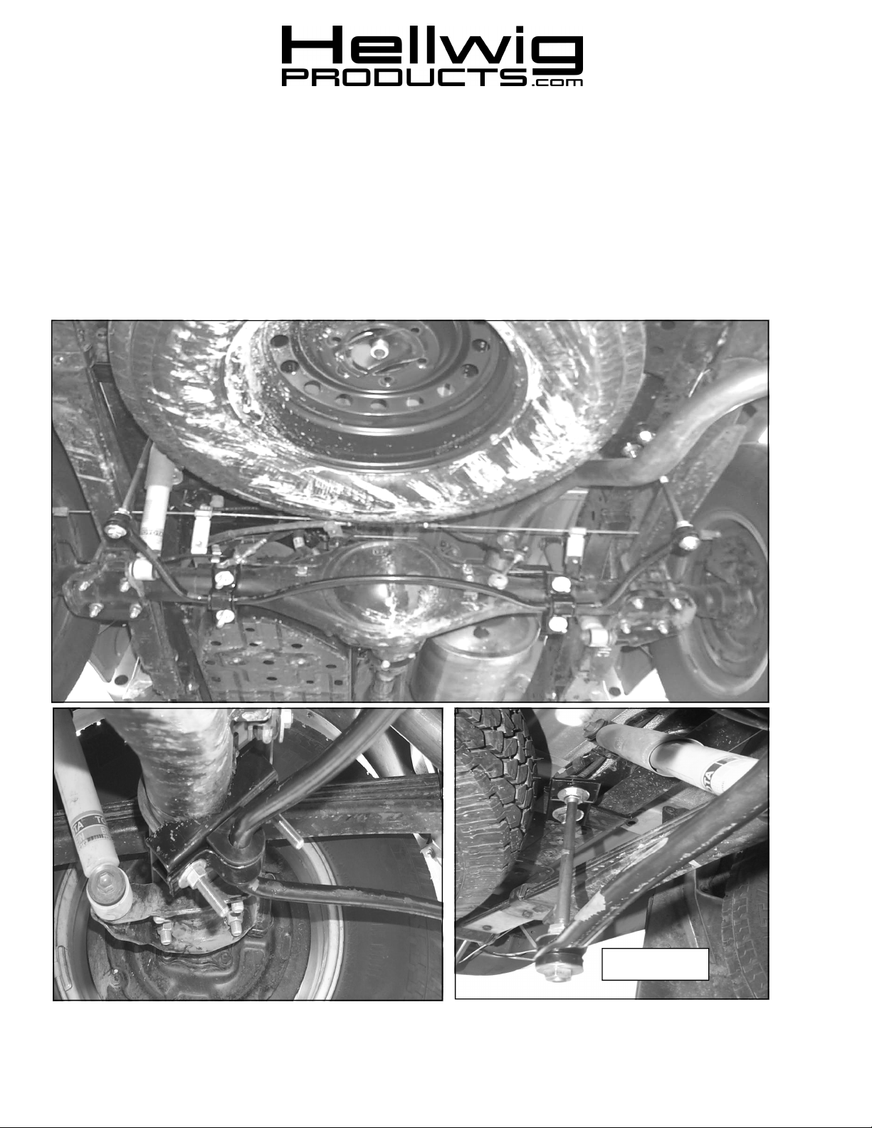
DRIVERS SIDE
7628 (R-7628) 12/29/03
559-734-7451 800-367-5480 FAX 559-734-7460
PASSENGER SIDE
TORQUE TABLE
BOLT SIZE: 3/8” = 20-30 ft. lbs. – 7/16” = 35-45 ft. lbs. – ½” = 50-70 ft. lbs. – 9/16” = 70-90 ft. lbs.
SAFETY: BEFORE STARTING YOUR INSTALLATION, BE SURE TO SET PARKING BRAKE AND CHOCK TIRES.
NOTE: TO EASE INSTALLATION AND TO PROPERLY ADJUST BAR, THE WEIGHT OF THE VEHICLE MUST BE ON
THE SUSPENSION, AS IF DRIVING DOWN THE ROAD. DO NOT RAISE VEHICLE BY FRAME.
NOTE: THIS UNIT IS DESIGNED TO MOUNT TO THE BOTTOM REAR OF THE AXLE TUBES WITH THE
ARMS OF THE BAR TOWARDS THE REAR OF THE VEHICLE.
1. As per the diagram, Place the D-shaped poly bushings onto the straight areas of the sway bar on each side of the center
hump.
2. Hold the bar up to the axle and locate the position on the axles to mount to U-bolts. Be sure to put the U -bolts under any
brake lines, wires or hoses on the axle to avoid any possible damage. The threads of the U-bolts will point downward and
slightly rearward.
3. Place the saddle brackets onto the U-bolts on the axles. Place the U-plates over the D-bushings on the bar and attach the
bar to the U-bolts and saddles with flat washers and nuts provided. LEAVE LOOSE AT THIS TIME to allow for adjustments later.
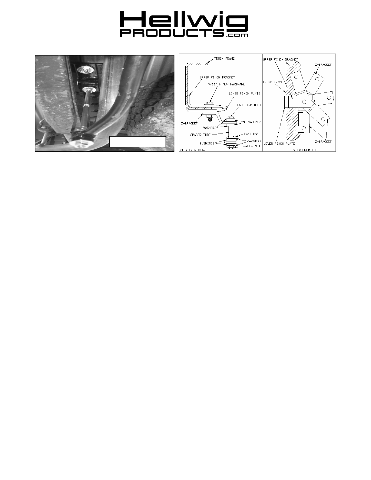
4. As per the Photos and Diagrams, assemble the end links between the ends of the short end of the Z-brackets. Tight en only
until the acorn nuts bottom. DO NOT OVER TIGHTEN.
5. Raise the bar ends upward to be about level with frame. Rotate the Z-brackets around to locate the area on the frame to
attach the pinch brackets. This should be to the rear of the end link on the drivers side and forward of the end link on the
passenger side. See the Diagram to properly attach the frame pinch brackets to the frame.
6. Use the 9/16” mounting hardware and attach the upper L-shaped pinch bracket, lower pinch bracket and the Z-bracket to
the frame. See Diagram. The pinch bolt will be just inside the frame. LEAVE LOOSE to allow for adjustment. Move any
wires or hoses inside the frame out of the way of the pinch bracket to avoid any damage.
7. Align the bar side to side through the bushings to be centered as possible. Rotate the bar front to rear by rotating the Ubolts on the axle. Adjust the frame brackets so end links are as straight up and down as possible. Be sure the bar does not
contact the differential, Drivers side shock, or the leaf spring. The Z-brackets can be rotated to any direction to best align
the end links on your particular vehicle.
8. Torque all of the mounting hardware to the specified rate. Bounce the vehicle checking for clearance on all undercarriage
components ie: exhaust, shocks etc. Recheck your installation periodically on a regular basis.
ATTENTION INSTALLER: BE SURE THE CUSTOMER RECEIVES THIS INSTRUCTION SHEET, ALL IMPORTANT
NOTE CARDS, WARNING CARDS, AND THE WARRANTY FORM.
7628 (R-7628) 12/29/03
 Loading...