

Page 1
harman/kardon
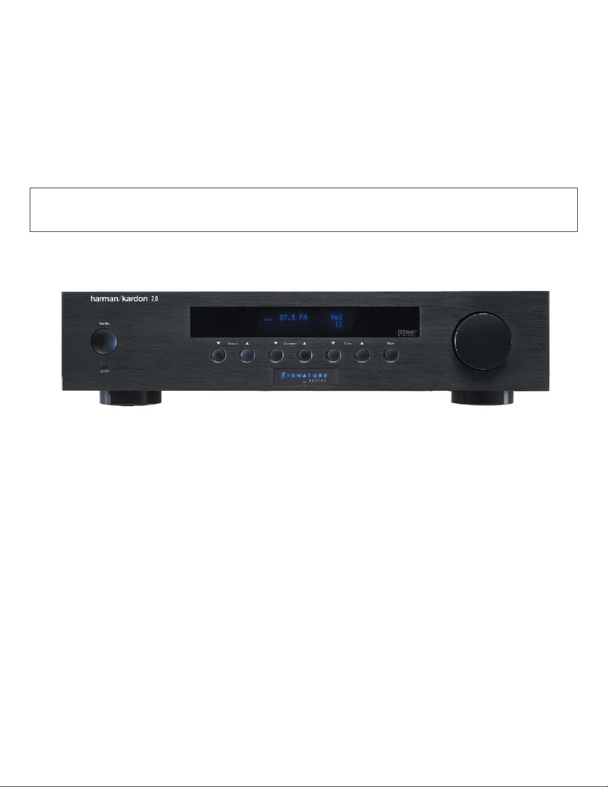
SIGNATURE 2.0
PROCESSOR/TUNER
SERVICE MANUAL
ESD , LEAKAGE, SAFETY ……….…..…....2
BASIC SPECIFICATIONS…………………..5
FEATURES…………………………………….7
QUICK START GUIDE………………………..9
FRONT P A NEL CONTRO L S ………..…..….13
REAR PANEL CONNECTIONS……………1 5
REMOTE CONTROL FUNCTIONS……….17
TROUBLESHOOTING GUIDE…...……..…21
PROCESSOR RESET……………….….…..21
TROUBLESHOOTING CHART……………23
BASS/TREBLE CHARTS……………………24
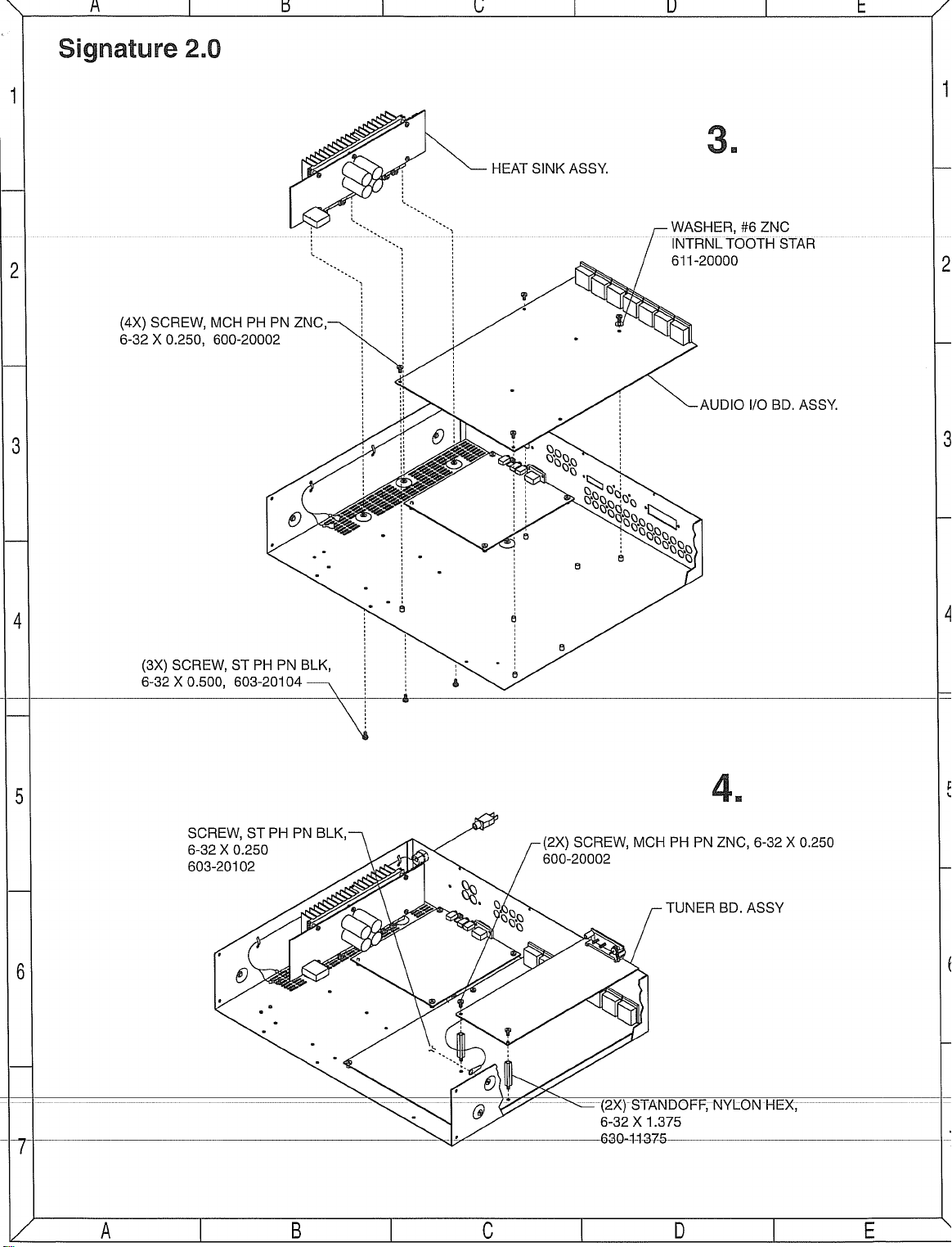
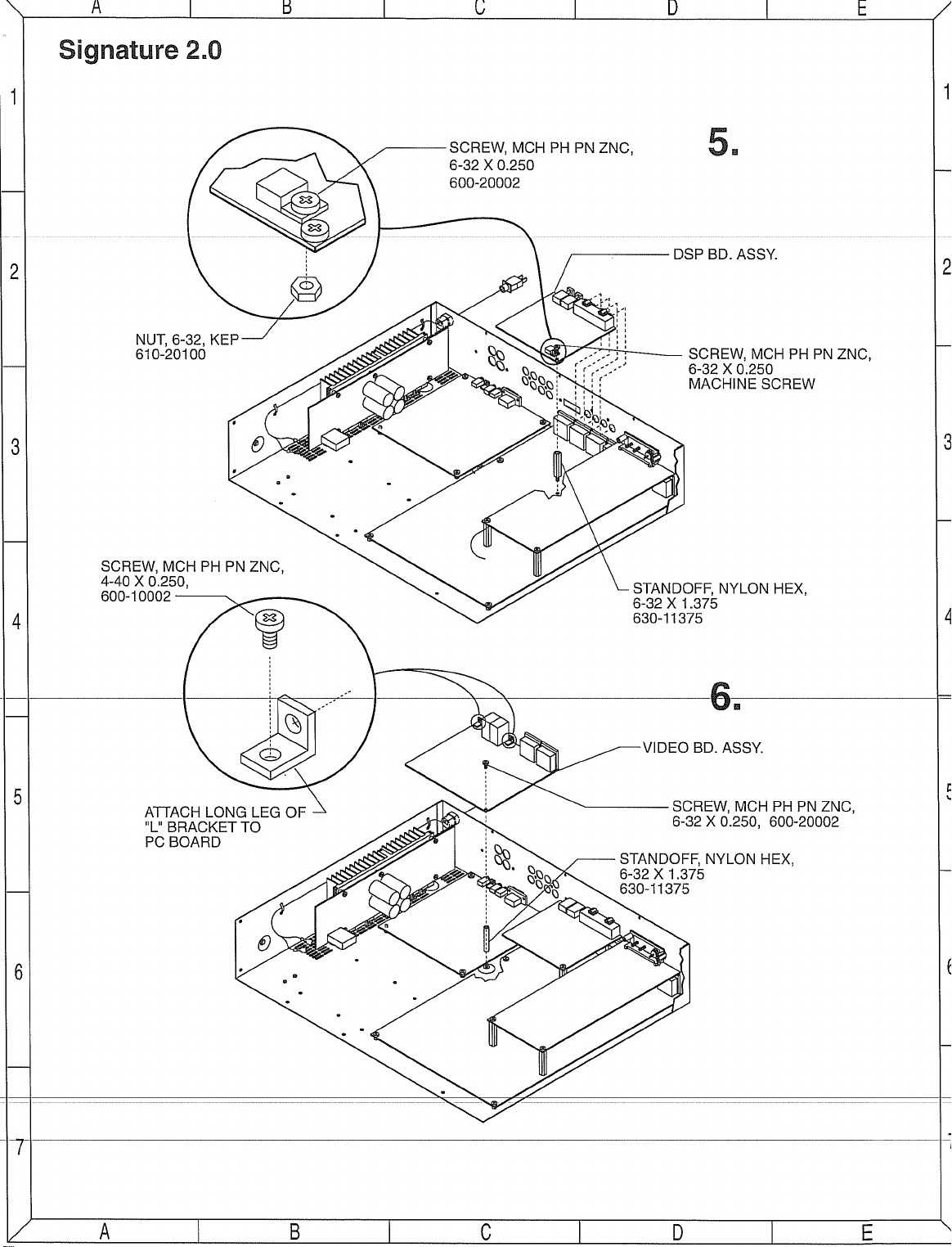
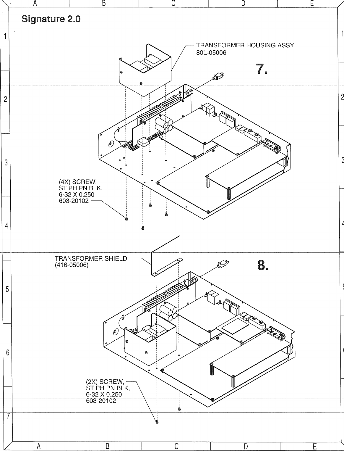
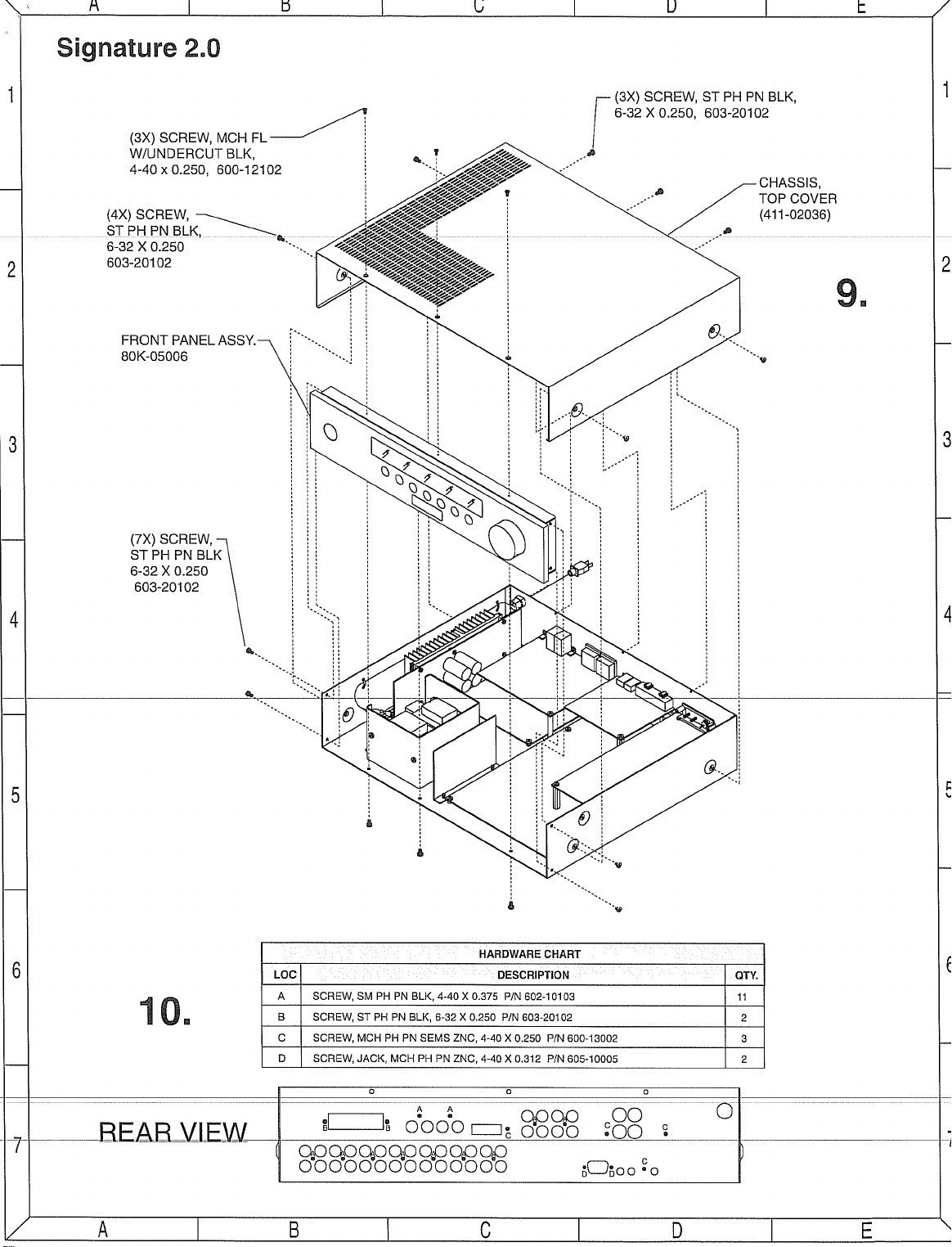
MECHANICAL ASSEMBLY…………………25
harman/kardon, Inc.
CONTENTS
BULLETIN HK9708……………….….………30
BULLETIN HK9709… ……………….….……31
BULLETIN HK9904… ……………….….……32
BULLETIN HK 2000-07……………….….…..33
IC U305 Replacement Instructions………..34
Signature 2.0 Upgrade Procedure………...35
VERSION CHANGES………………………36
Auto Detect Mode ON………………………40
SCHEMATICS……………………………….41
PCB DRAWINGS………….………………..70
ELECTRICAL PARTS LIST…………….….76
250 Crossways Park Dr.
Woodbury, New York 11797 Rev0 8/2006
Page 2
Signature 2.0 Processor/Tuner harman/kardon
2
Some semiconductor (solid state) devices can be damaged easily by static electricity. Such components commonly are called
Electrostatically Sensitive (ES) Devices. Examples of typical ES devices are integrated circuits and some field effect transistors and
semiconductor "chip" components.
The following techniques should be used to help reduce the incidence of component damage caused by static electricity.
1. Immediately before handling any semiconductor component or semiconductor-equipped assembly, drain off any electrostatic charge on
your body by touching a known earth ground. Alternatively, obtain and wear a commercially available discharging wrist strap device,
which should be removed for potential shock reasons prior to applying power to the unit under test.
2. After removing an electrical assembly equipped with ES devices, place the assembly on a conductive surface such as aluminum foil, to
prevent electrostatic charge build-up or exposure of the assembly.
3. Use only a grounded-tip soldering iron to solder or unsolder ES devices.
4. Use only an anti-static solder removal device. Some solder removal devices not classified as "anti-static" can generate electrical charges
sufficient to damage ES devices.
5. Do not use freon-propelled chemicals. These can generate electrical change sufficient to damage ES devices.
6. Do not remove a replacement ES device from its protective package until immediately before you are ready to install it. (Most replacement
ES devices are packaged with leads electrically shorted together by conductive foam, aluminum foil or comparable conductive material.)
7. Immediately before removing the protective material from the leads of a replacement ES device, touch the protective material to the
chassis or circuit assembly into which the device will be installed.
CAUTION :
8. Minimize bodily motions when handling unpackaged replacement ES devices. (Otherwise harmless motion such as the brushing together
or your clothes fabric or the lifting of your foot from a carpeted floor can generate static electricity sufficient to damage an ES devices.
Be sure no power is applied to the chassis or circuit, and observe all other safety precautions.
Each precaution in this manual should be followed during servicing.
Components identified with the IEC symbol in the parts list are special significance to safety. When replacing a component identified with
, use only the replacement parts designated, or parts with the same ratings or resistance, wattage, or voltage that are designated in the
parts list in this manual. Leakage-current or resistance measurements must be made to determine that exposed parts are acceptably
insulated from the supply circuit before retuming the product to the customer.
Page 3
Signature 2.0 Processor/Tuner harman/kardon
3
Before returning the unit to the user, perform the following safety checks :
1. Inspect all lead dress to make certain that
leads are not pinched or that hardware is not
lodged between the chassis and other metal
parts in the unit.
2. Be sure that any protective devices such as
nonmetallic control knobs, insulating fish-
papers, cabinet backs, adjustment and
compartment covers or shields, isolation
resistor-capacity networks, mechanical
insulators, etc. Which were removed for the
servicing are properly re-installed.
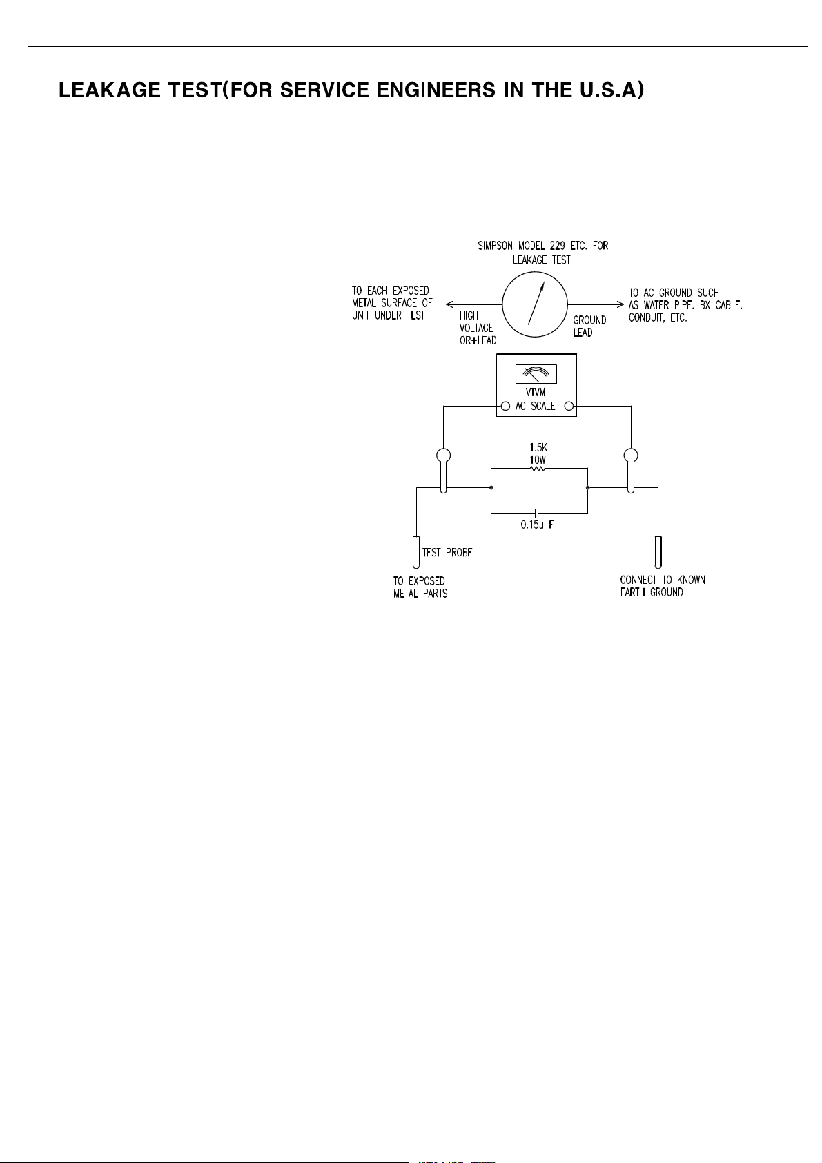
3. Be sure that no shock hazard exists ; check for leakage
current usingSimpson Model 229 Leakage Tester, standard
equipment item No. 21641, RCA Model WT540A or use
alternate method as follows : Plug the power cord directly
Into a 120 volt AC receptacle (do not use an Isolation
Transformer for this test). Using two clip leads, connect a
1500 ohms,10watt Resistor paralleledby a 0.15uFcapacitor,in series withall exposed metal cabinetparts and aknown earth ground,such
as a water pipe or conduit. Use a VTVM or VOM with 1000 ohms per volt, or higher sensitivity to measure the AC voltage drop across the
resistor. (See diagram) Move the resistor connection to each exposed metal part having a return path to the chassis (antenna, metal,
cabinet, screwheads, knobsand controlshafts, escutcheon, etc.) and measure the ACvoltage dropacross theresistor.(This test should be
performed withthe 0.35 volt RMS or more is excessive and indicates a potential shock hazardwhich must becorrected before returningthe
unit to the owner.
Page 4
Safety Information
2
Signature 2.0
Important Safety Information
Verify Line Voltage Before Use
This Signature 2.0 has been designed for use with
120-volt AC current. Connection to a line voltage other
than that for which it is intended can create a safety and
fire hazard, and may damage the unit.
If you have any questions about the voltage requirements for your specific model, or about the line voltage
in your area, contact your selling dealer before plugging
the unit into a wall outlet.
Do Not Use Extension Cords
To avoid safety hazards, use only the power cord
attached to your unit. We do not recommend that
extension cords be used with this product. As with all
electrical devices, do not run power cords under rugs
or carpets or place heavy objects on them. Damaged
power cords should be replaced immediately with cords
meeting factory specifications.
Handle the AC Power Cord Gently
When disconnecting the power cord from an AC outlet,
always pull the plug, never pull the cord. If you do not
intend to use the unit for any considerable length of
time, disconnect the plug from the AC outlet.
Do Not Open The Cabinet
There are no user-serviceable components inside this
product. Opening the cabinet may present a shock
hazard, and any modification to the product will void
your guarantee. If water or any metal object such as
a paper clip, wire or a staple accidentally falls inside
the unit, disconnect it from the AC power source
immediately, and consult an authorized service station.
CATV or Antenna Grounding
If an outside antenna or cable system is connected to
this product, be certain that it is grounded so as to
provide some protection against voltage surges and static
charges. Section 810 of the National Electrical Code,
ANSI/NFPA No. 70-1984, provides information with
respect to proper grounding of the mast and supporting
structure, grounding of the lead-in wire to an antenna
discharge unit, size of grounding conductors, location
of antenna discharge unit, connection to grounding
electrodes and requirements of the grounding electrode.
NOTE TO CATV SYSTEM INSTALLER:
This reminder is provided to call the CATV (Cable TV)
system installer’s attention to article 820-40 of the NEC
that provides guidelines for proper grounding and, in
particular, specifies that the cable ground shall be
connected to the grounding system of the building, as
close to the point of cable entry as possible.
Installation Location
■ To assure proper operation, and to avoid the potential
for safety hazards, place the unit on a firm and level
surface. When placing the unit on a shelf, be certain
that the shelf and any mounting hardware can support
the weight of the product.
■ Make certain that proper space is provided both above
and below the unit for ventilation. If this product will
be installed in a cabinet or other enclosed area, make
certain that there is sufficient air movement within
the cabinet. Under some circumstances a fan may
be required.
■ Do not place the unit directly on a carpeted surface.
■ Avoid installation in extremely hot or cold locations,
or an area that is exposed to direct sunlight or
heating equipment.
■ Avoid moist or humid locations.
■ Do not obstruct the ventilation slots on the top of the
unit, or place objects directly over them.
CAUTION:
TO REDUCE THE RISK OF ELECTRIC SHOCK, DO NOT REMOVE
COVER (OR BACK). NO USER-SERVICEABLE PARTS INSIDE. REFER
SERVICING TO QUALIFIED SERVICE PERSONNEL.
WARNING:
TO REDUCE THE RISK OF FIRE OR ELECTRIC SHOCK,
DO NOT EXPOSE THIS APPLIANCE TO RAIN OR MOISTURE.
CAUTION:
TO PREVENT ELECTRIC SHOCK, MATCH WIDE
BLADE OF PLUG TO WIDE SLOT, FULLY INSERT.
ATTENTION:
POUR EVITER LES CHOCS ELECTRIQUES, INRODUIRE LA
LAME LA PLUS LARGE DE LA FICHE DANS LA BORNE CORRESPONDANTE DE
LA PRISE ET POUSSER JUSQU'AU FOND.
The lightning flash with arrowhead
symbol, within an equilateral triangle, is
intended to alert the user to the
presence of uninsulated “dangerous voltage”
within the product’s enclosure that may be of
sufficient magnitude to constitute a risk of
electric shock to persons.
The exclamation point within an
equilateral triangle is intended to
alert the user to the presence of
important operating and maintenance
(servicing) instructions in the literature
accompanying the appliance.
CAUTION
RISK OF ELECTRIC SHOCK
DO NOT OPEN
4
Signature 2.0 Processor/Tuner harman/kardon
Page 5

Technical Specifications
65
Signature 2.0
Signature 2.0 Processor /Tuner Specifications
Inputs:
Analog Audio: Six Stereo pairs via RCA jacks
Digital Audio: Four Coaxial S/P-DIF, Two Optical TosLink
External Adapter: Six Direct Analog channels via RCA jacks
Composite Video: Six RCA jacks
S-Video: Two 4-pin mini DIN
IR Sensor Input: 3.5mm mono mini-plug
Outputs:
Main Audio: Six Analog Outputs via RCA jacks (left, center, right, right surround,
left surround, subwoofer)
Main Video: One Composite RCA jack output paralleled with
one S-Video 4-pin mini DIN
Record Audio: Two pair (paralleled) analog via RCA jacks
Record Video: One Composite via RCA jack paired with
one S-Video via 4-pin mini DIN
IR Sensor: Loop-through output via 3.5mm mono mini plug
Accessory Trigger: 6 – 12 volt DC via 3.5mm mono mini plug, tip positive, 150mA maximum.
Surround Modes:
Analog: Dolby Pro Logic, Four Movie Modes, Four Music Modes, Stereo,
Mono, Mono +
Digital: Dolby Digital, Dolby Digital Late Night, Dolby Digital
Pro Logic, Dolby Digital Mono, DTS 5.1, DTS 4-Channel,
DTS 2-Channel, Stereo, Mono +
Preamplifier:
Frequency Response: Front Channels (Analog Stereo): 20Hz to 50kz, ± 0.5dB
Center and Surround Channels: 20Hz to 30kHz, ± 1dB
Subwoofer Channel: 10Hz to 100Hz, ± 1dB
THD + N: 0.03%, 20Hz to 20kHz
S/N Ratio: >–87dBr, 20Hz to 20kHz
Crosstalk: <60dB
Input Impedance: Audio: >10K½
Video: 75½
Output Impedance: Audio: 300½
Video: 75½
Crossovers: Low Pass: 3 Pole (18dB/Octave) @ 100Hz
High Pass: 3 Pole (18dB/Octave) @ 100Hz
Tone Controls: Treble Cut: –0dB to –8dB in 2dB steps @ 10kHz shelving
Bass Boost: +0dB to +8dB in 2 steps @ 50Hz
Video Standards: NTSC, PAL
5
Signature 2.0 Processor/Tuner harman/kardon
Page 6

Technical Specifications
66
Signature 2.0
Signature 2.0 Processor /Tuner Specifications (continued)
Tuner Section FM:
Frequency Range: 87.5 to 108.0MHz in 200kHz steps
Usable Sensitivity: <1.0 µV/11.2dBf
Signal-To-Noise: 70dB (Stereo, A-weighted)
S/N 50dB Sensitivity: <45dBf
THD + N: <0.5%
Capture Ratio: <2.5dB
AM Suppression: >50dB
Image Rejection: >70dB (@ 106MHz)
IF Rejection: >85dB
Effective Selectivity: >50dB (±400kHz)
Stereo Separation: >40dB (1kHz)
RDS Modes: Station ID, Program Type, Radio Text Data, Program Type Search
Tuner Section AM:
Frequency Range: 520 – 1710 kHz in 10kHz steps
Signal-To-Noise Ratio: >40dB
Usable Sensitivity: ²500µV/M
Selectivity: ³30dB (± 10kHz)
General:
Power Requirement: AC 115V/60Hz
Power Consumption: 5.5W Idle, 75W Maximum
Dimensions: (Max, including knobs, jacks, buttons)
Width: 17
3
⁄8 inches (441mm)
Height: 4
1
⁄8 inches (105mm)
Depth: 15
3
⁄
8 inches (395mm)
Weight: 22 lbs. (10.5 kg)
All features and specifications are subject to change without notice.
*
Trademarks of Dolby Laboratories.
†
DTS and DTS Surround are trademarks of Digital Theater Systems.
6
Signature 2.0 Processor/Tuner harman/kardon
Page 7
Introduction
1
Signature 2.0
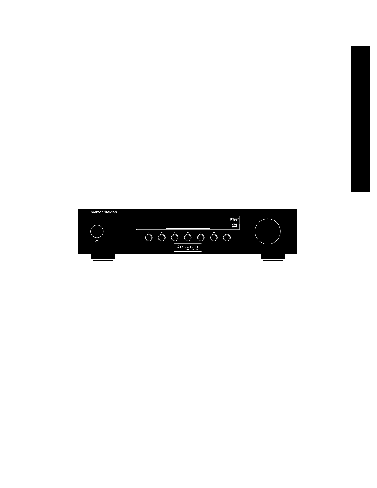
Congratulations! With the purchase of a Harman
Kardon Signature Series product you are about to begin
many years of listening enjoyment. The Model 2.0
Processor/Tuner has been designed to provide all the
excitement and detail of motion picture soundtracks and
reproduce every subtle nuance of your favorite musical
selection. On-board Dolby* Digital and DTS†decoding
enables the 2.0 to deliver six channels of fully discrete
sound from the exciting new digital audio formats that
are a part of DVD and HDTV broadcasts. A wide selection of matrix decoding modes delivers full compatibility
with conventional Dolby Surround stereo and mono
programs. The 2.0 is also ready to accept future surround
systems through the use of six-channel direct inputs
that accommodate optional outboard decoders for future
surround systems.
Mute
TuneSurroundSource
2.0
Standby
On/Off
DVD Vol
Dolby Digital 10
While complex digital circuits are hard at work within
the 2.0, a simple F menu system and learning remote
control make the unit easy to install and operate.
In addition to selecting from a variety of audio/video
sources, the Signature 2.0 is equipped with the latest
in tuner technology, including the RDS data system
that automatically identifies FM stations transmitting
special data and provides information they transmit
about the station’s programming. The RDS system even
lets you automatically search for a station with a specific
program type from the participating stations in your
reception area.
To obtain maximum benefit from the Signature 2.0’s
many features we urge you to take a few minutes to read
through this manual. That will ensure that connections
to playback sources, power amplifiers and other external
devices are made properly. In addition, a few minutes
spent learning the functions for the various controls and
the meaning of the on-screen and front panel display
messages will enable you to take advantage of all the
power the Signature 2.0 is able to deliver.
Harman Kardon has been a part of the audio world
since it invented the first high-fidelity receiver over fortyfive years ago. With the combination of state-of-the-art
circuitry and time honored design philosophies, the
Signature 2.0 is one of the most innovative products
ever offered by Harman Kardon. Should you have any
questions about this product, its operation or installation
that are not answered in this manual please contact your
retailer or custom installer. They are your best source for
product information. You may also contact Harman Kardon
via the World Wide Web at www.harmankardon.com
The following are among the 2.0’s many features:
■ On-Board Dolby Digital and DTS Decoding
■ Multiple Coax and Optical Digital Inputs
■ Composite and S-Video Switching
■ Easy-To-Use On-Screen Menu Control System
■ FM Stereo/AM Tuner With RDS Data System
and 30 Presets
■ Learning Remote Control Pre-Programmed With
Harman Kardon and RC-5 Control Codes
■ Trigger Output For Automatic Control of Signature
Series Power Amplifiers
■ RS-232 Control Port For Connection To External
Automation Systems
■ Six-Channel Direct Inputs For Use With External
Audio Adapters or Decoders.
7
Signature 2.0 Processor/Tuner harman/kardon
Page 8

Safety Information
3
Signature 2.0
Cleaning
When the unit gets dirty, wipe it with a clean, soft dry
cloth. If necessary, wipe it with a soft cloth dampened
with mild soapy water, then a fresh cloth with clean
water. Wipe dry immediately with a dry cloth. NEVER
use benzene, aerosol cleaners, thinner, alcohol or any
other volatile cleaning agent. Do not use abrasive
cleaners, as they may damage the finish of metal parts.
Avoid spraying insecticide near the unit.
Moving The Unit
Before moving the unit, be certain to disconnect any
interconnection cords with other components, and make
certain that you disconnect the unit from the AC outlet.
Important information for the user
NOTE: This equipment has been tested and found to
comply with the limits for a Class B digital device,
pursuant to Part 15 of the FCC Rules. The limits are
designed to provide reasonable protection against
harmful interference in a residential installation. This
equipment generates, uses and can radiate radio
frequency energy and, if not installed and used in
accordance with the instructions, may cause harmful
interference to radio communication. However, there is
no guarantee that harmful interference will not occur in
a particular installation. If this equipment does cause
harmful interference to radio or television reception,
which can be determined by turning the equipment
off and on, the user is encouraged to try to correct the
interference by one or more of the following measures:
■ Reorient or relocate the receiving antenna.
■ Increase the separation between the equipment
and receiver.
■ Connect the equipment into an outlet on a circuit
different from that to which the receiver is connected.
■ Consult the dealer or an experienced radio/TV
technician for help.
This device complies with Part 15 of the FCC Rules.
Operation is subject to the following two conditions:
(1) this device may not cause harmful interference,
and (2) this device must accept interference received,
including interference that may cause undesired
operation.
NOTE: Changes or modifications may cause this unit to
fail to comply with Part 15 of the FCC Rules and may
void the user’s authority to operate the equipment.
Unpacking and Installation
The carton and shipping materials used to protect your
new 2.0 during shipment were specially designed to
cushion it from shock and vibration. We suggest that you
save the carton and packing materials for use in shipping
if you move or should the unit ever need repair.
To minimize the size of the carton in storage, you may
wish to flatten it. This is done by carefully slitting the
tape seams on the bottom and collapsing the carton
down to a more two-dimensional appearance. Other
cardboard inserts may be stored in the same manner.
Packing materials that cannot be collapsed should be
saved along with the carton in a plastic bag.
If you do not wish to save the packaging materials,
please note that the carton and other sections of the
shipping protection are recyclable. Please respect the
environment and discard those materials at a local
recycling center.
Typographic Conventions
In order to help you use this manual with diagrams of
the remote control, front panel controls, rear panel
connections and on-screen menus, certain conventions
have been used.
Example
– (bold type) indicates a specific
remote control or front panel button, or rear panel
connection jack
Example
– (OCR type) indicates a message that is
visible through the on-screen menu system or on the
front panel information display
1
– (number in a square) indicates a specific front
panel control
a
– (number in an oval) indicates a button or indicator
on the remote
¡
– (number in a circle) indicates a rear panel connection
8
Signature 2.0 Processor/Tuner harman/kardon
Page 9

Quick Start Instructions
4
Signature 2.0
Quick-Start Instructions
The Signature 2.0 is a powerful, yet easy-to-use product.
In order to obtain the maximum benefit from its many
features and options, it is strongly recommended that
you take the time to carefully read the instructions in the
manual. It contains a wealth of information that will help
you to safely and properly install and use this product.
We realize, however, that you may be anxious to use
your system, so the following steps are provided to outline the minimum instructions needed to get everything
connected and “on the air.” Please follow the directions
carefully in order to avoid damage to the Signature 2.0
or other components in your system.
If you choose to take advantage of these Quick-Start
instructions we nevertheless urge you to read through the
Owner’s Manual at a later time so that your system may
be adjusted for optimal performance. That small investment of your time will yield major dividends in the long
term in the form of hours of greater listening pleasure.
IMPORTANT NOTE: Before connecting your new
Signature 2.0, you will need to physically locate it
in your system.
To ensure proper operation, and to prevent
possible heat damage, it is important that the 2.0
NOT be placed on top of an amplifier such as the
Signature 2.1, or other heat sources. For optimal air
circulation, we strongly recommend that the 2.0 be
placed on a shelf by itself, with 11/2 to 2 inches of
clearance between the top of the 2.0 and any shelf
or equipment above it.
Equipment Required for Quick-Start
Installation:
✓ Signature 2.0 Processor/Tuner and Supplied
Accessories
✓ Front Left, Center and Right Speakers
✓ Left and Right Surround Speakers
✓ Five Channels of Audio Power Amplification
✓ Powered Subwoofer or Passive Subwoofer and
External Amplifier
✓ Source Equipment (e.g., VCR, DVD, CD, Satellite
Receiver, etc.)
✓ Interconnect and Speaker Cables
NOTE: If your equipment does not match the list
above you should NOT use the Quick-Start instructions,
as additional settings must be made beyond those shown
on the next two pages. For complete installation
instructions, see page 19.
9
Signature 2.0 Processor/Tuner harman/kardon
Page 10
Quick Start Instructions
5
Signature 2.0
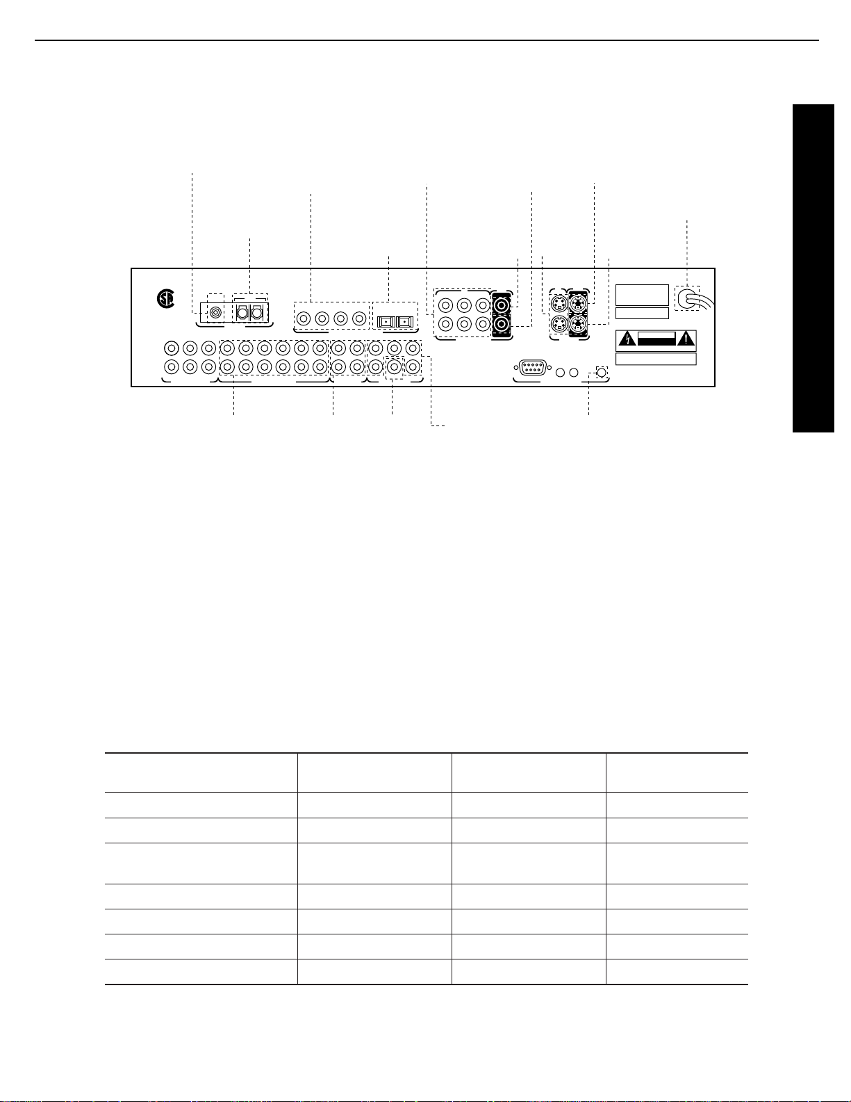
DIGITAL AUDIO DATA INPUTS
ANTENNA
SUB
1 2 3 4 5 6SURRCENTER SURRCENTERFRONT
1 2 3 4
65
32
RS-232
115V
~
60Hz
75 WATTS
IRINIR
OUT
TRIGGER
OUTPUT
FM AM
ANALOG AUDIO INPUTS
AUDIO OUTPUTS
REC OUTPUTS6-CH DIRECT INPUTS
EXTERNAL CONTROLS
L
R
L
R
FRONT
1
1
Manufactured under license from Dolby Laboratories Licensing
Corporation. "Dolby", "AC-3", "Pro Logic" and the Double-D symbol
are trademarks of Dolby Laboratories Licensing Corporation.
Copyright 1992 Dolby Laboratories, Inc. All rights reserved.
SERIAL NUMBER
MODEL NO.: SIGNATURE SERIES 2.0
HARMAN KARDON
NORTHRIDGE
CALIFORNIA, USA
MADE IN USA
AVIS: RISQUE DE CHOC ELECTRIQUE - NE PAS OUVRIR
CAUTIONCAUTION
RISK OF ELECTRIC SHOCK
DO NOT OPEN
WARNING:
TO REDUCE THE RISK OF FIRE
OR ELECTRIC SHOCK DO NOT EXPOSE THIS
EQUIPMENT TO RAIN OR MOISTURE.
OUT
MAIN
OUT
IN
MAIN
4
5 6
2
S – VIDEO
COMPOSITE VIDEO
REC
REC
SUB
IN
®
NRTL /C
LR110480
CSA E65
Connect to output
of composite
video sources
Connect 75-ohm
FM antenna here
Connect AM loop
antenna here
Connect to coaxial
digital audio output
of A/V sources, DVD,
HDTV, CD, etc.
Connect to optical
digital audio output
of A/V sources, DVD,
HDTV, CD, etc.
Connect to
composite
video input of
main monitor
Connect to
composite
video input
of VCRs
Connect to
S-Video input
of main monitor
Connect to
S-Video input
of VCRs
Connect to analog audio
output of A/V sources,
CD, tuner, etc.
Connect to audio
input of VCR or
audio recorders
Connect to
a powered
subwoofer
or subwoofer
amplifier
Connect to
inputs of audio
power amplifiers
Connect to "Trigger
In" jack on Signature
Series or other compatible
power amplifier
Connect AC Power
to non-switched
wall outlet
Connect to
S-Video
output
sources
Quick Start Connection and Setup
Remote
Button
TV
Video 1
Video 2
Video 3
Tuner
CD
Tape
Aux
Source
Equipment
Cable Box, Satellite
Receiver, TV Tuner
VCR
DVD
HDTV, Satellite with Digital
Audio, Laser Disc
Tuner (internal)
CD Player
Cassette or Tape Deck
Outboard Decoder
Video Input
Connection
Analog 2
Analog 1
Digital 1
Digital 2
(Internal Tuner)
Digital 3
Analog 5
6-Ch. Direct Inputs
Audio Input
Connection
Composite 2
Composite 1
S-Video 1
S-Video 2
Composite 2
N/A
N/A
Composite 1
1. Before proceeding, make certain that all equipment, including the 2.0, is unplugged from AC power. This will prevent
any damage due to the unintended activation of automatic turn-on circuits.
2. Use high-quality audio and video interconnect cables to connect your source equipment to the rear of the 2.0 as shown
in the diagram above and the table below. It is important to note that unlike conventional audio/video equipment, the 2.0
does not have inputs that are labeled for connection to a specific type of equipment (e.g., inputs labeled “CD,” “Tape” or
“VCR”). Instead, the 2.0 allows you to connect the analog or digital audio and composite or S-Video outputs of your source
equipment to any of the inputs. Then, using the setup procedures detailed on page 28 of this manual, you can custom
configure the input sources. However, for a quick starting point, follow the input suggestions outlined in the chart shown
below. They conform to the preset conditions for the 2.0.
10
Signature 2.0 Processor/Tuner harman/kardon
Page 11

Quick Start Instructions
6
Signature 2.0
NOTE: To use the sources when they are connected as
shown in the chart on the previous page, press the button
name shown. The button names may not correspond
exactly to the type of source used for any input profile,
but you may rename the input source for the on-screen
display by following the instructions shown on page 27
of this manual.
3. Connect the video “Record Inputs” of your VCR to the
Composite
or
S-Video “Rec” Outputs
.
4. Connect the audio “Record Inputs” of your VCR
and/or audio tape recorder to the
“Rec” Outputs
on
the rear of the 2.0. There is no problem in sending the
feed to both recorders and two recordings may be made
at one time from the same source.
5. Connect the
Composite
or
S-Video “Main”
Outputs
to the matching Composite or S-Video input
on your TV monitor or projector.
6. Connect the AM and FM antennae supplied with the
2.0 to the proper antenna connections on the rear panel.
7. If a Signature Series audio power amplifier, or other
compatible amplifier, is being used, connect the power
trigger cable supplied with the 2.0 to the
Trigger
Output
on the 2.0 and the amplifier’s compatible
Trigger Input.
8. Connect the
Audio Outputs
of the 2.0 to the inputs
of your five-channel power amplifier. Be certain that
channels are properly matched (e.g., connect left to left,
right to right, etc.) Connect the
Sub Output
to the
mono “line level” input of a powered subwoofer, or to
the audio input of the amplifier channel feeding a passive
subwoofer. Connect the audio amplifier to the speakers,
carefully following the instructions provided with the
speaker and amplifier, and ensure that polarity is
matched between the speaker and amplifier when
connections are made.
9. Install the batteries in the remote control, being careful
to observe the (+) and (–) polarity indicators on the
remote and the batteries.
10. Connect all devices, including the 2.0, to AC
power and turn everything on EXCEPT for the 2.0
and any audio amplifier not connected to the 2.0’s
triggered output.
11. Press the
Master Power Switch
on the 2.0 in until
it latches and is flush with the front panel. A green
standby LED will light, and the front panel
Information
Display
will come on briefly to display the software
version installed in your unit and then a
Power Off
Standby
message will show briefly. The unit will then
go into the Standby mode.
•
To use the On-Screen Menu System, make certain that
your TV or other video display device is turned on and
switch to the proper video input at this point.
12. To turn the 2.0 on, press either the front panel
Standby
button, the
Main On
button on the remote,
or any of the source buttons on the remote (e.g., TV,
Vid 1, Tuner
, etc.). The front panel
Information
Display
will illuminate, the amber standby LED will
go out and be replaced by blue illumination behind the
word “Signature” on the front panel. A message will
briefly appear in the on-screen display with the source,
surround mode and volume.
•
If you are using a Signature Series amplifier or another
compatible amplifier connected to the
Trigger
Output
jack, it will receive a turn-on signal as soon
as the 2.0 is turned on. Note that with most amplifiers
there will be a short, intentional delay between the
turn-on signal and when the amplifier sends signals
to the speakers. This is a normal function designed to
prevent damage to your speakers.
•
If you are using an amplifier not controlled by the 2.0’s
Trigger Output
, turn it on at least 10 seconds
AFTER the 2.0 is turned on.
11
Signature 2.0 Processor/Tuner harman/kardon
Page 12

Quick Start Instructions
7
Signature 2.0
13. The factory presets for most settings are designed to
accommodate the typical home-theater system. If the
speakers being used are a “satellite/subwoofer” system
with compact speakers at the front left/right, center and
surround positions, and a subwoofer connected for lowfrequency reproduction, no further adjustment is needed.
However, if you have larger front, center or surround
speakers that are capable of low-frequency reproduction
below 100Hz, or if a subwoofer is not installed, you
should change the Speaker Setup, as shown on page 24
of this manual.
14. You may change the input source by pressing the
front panel
Source
buttons or any of the
Source
buttons on the remote. Volume for the 2.0 may be raised
or lowered using the front panel
Volume
knob or the
Volume Up/Down
buttons on the remote. Finally, to
change the surround mode, press
Surround
buttons on
the front panel or the
Mono +, Music, Movies
or
Stereo
buttons on the remote.
At this point you are “on the air”! Sit back and enjoy the
best in home entertainment.
Operating Hints
The following hints will help you to enjoy the sonic
power and operating flexibility of the Signature Series
2.0 while you become accustomed to the way it works.
Depending on the type of equipment in use in your
system, it may, or may not be necessary to follow
these hints:
•
If you change the Speaker Setup, keep in mind that the
changes apply to all modes. You may not change the
Speaker Setup for one mode, and not another.
•
When the front channel speakers are set to the LARGE
mode, the subwoofer output will only be active when a
Dolby* Digital source with Low-Frequency Effects (LFE)
or DTS are in use. In order to have a full-time output
from the subwoofer channel, the front speakers must be
set to SMALL. (This is the factory preset configuration.)
•
If the Surround Mode indication flashes in the front
panel display, that is an indication that the input source
is not compatible with the desired mode. The flashing
mode is not the one originally selected, rather, it is the
mode automatically selected by the 2.0 to match the
input source. For example, when the Pro Logic* mode
is selected, but a Dolby Digital source is playing, the
2.0 will automatically select Dolby Digital, but the
mode will flash to remind you that while it is correct,
it is not the mode originally selected.
•
Note that when a DVD is in use, the digital audio output is interrupted when the player is in the pause, fast
search, slow speed or reverse modes. Since the 2.0 does
not receive a digital signal in these cases, it will
momentarily try the Pro Logic mode as an alternate.
This temporary mode change does not indicate any
fault or problem with the 2.0, and the unit will return
to the Dolby Digital or DTS Mode shortly after the
DVD is put back into a standard play mode.
•
If one input source requires a significantly higher
volume level than others, or when there is a distinct
increase in the noise level or distortion with one input
in comparison to others, this is a sign that the input
level needs to be adjusted. See pages 29–30 of this
manual for instructions on adjusting the input level.
•
When certain DVD players are used, it is normal to hear
an occasional click or pop noise when the DVD player
is put back into play after being paused, or when some
DVD discs change chapters. This is a normal side effect
of the way in which some DVD players and digital
decoders work, and it does NOT indicate a problem
with the 2.0 or with your DVD player.
Of course, this is only the tip of the iceberg. Although
you have successfully completed a minimal installation
we strongly recommend that you take time to read this
manual thoroughly. It will show you how to use the
many features, modes and controls that are a vital part of
the Signature 2.0. Correct setup and installation is important to optimizing the sound quality of your new controller, and will also make it easier to operate. A few
minutes spent reading the manual and making certain
that your new 2.0 is set up to meet the individual
characteristics of your system and listening room will
enable the 2.0 to deliver all the performance it is
capable of.
12
Signature 2.0 Processor/Tuner harman/kardon
Page 13
Front Panel Controls
8
Signature 2.0
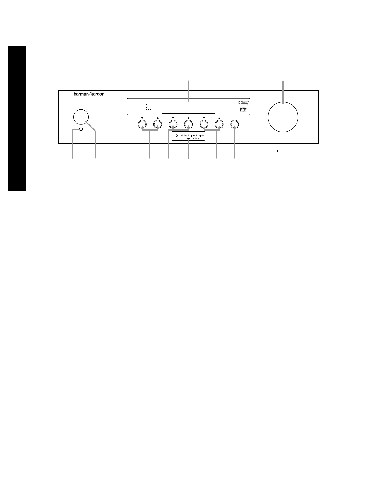
1 Master Power Switch:
This is the main power
control for the 2.0. To turn the unit on, press this switch
in until it latches and is flush with the front panel. To
turn the unit off press in briefly, and the switch will
unlatch and pop out. Once this switch is in the “ON”
position you may leave it there and use the remote
control or standby switch to turn the 2.0 on or off.
NOTE: Even when the
Master Power Switch
is in
the “OFF” position, the 2.0 is still connected to the AC
power source.
2 Standby Switch:
Press this switch to turn the unit
on from the Standby mode. Press it again to return to
the Standby mode. Note that in order for this switch to
operate the 2.0, the
Master Power Switch 1
must
be in the “ON” position, as indicated by the amber
Standby LED 5
.
3 Source Selectors:
Press these buttons to change
the input source selection. Use them to scroll through the
list of sources you watch and listen to.
4 Surround Selectors:
Press these buttons to
change the surround mode in use. Note that the list
of modes available is different for digital or analog
audio sources.
5 Standby LED:
When this indicator lights in an
amber color, the 2.0 is in the Standby mode, and it is
ready to be turned on or off when either the
Standby
Switch 2
, or the remote
Main On/Off a
is pressed.
When the
Standby LED
is out, but the
Power
Indicator 6
is illuminated in blue, the unit is on.
When both of these indicators are dark, the 2.0 is fully
off, indicating that the
Master Power Switch 1
is in
the “OFF” position or the 2.0 is not plugged into a live
AC power source.
6 Power Indicator:
This indicator is illuminated
in blue when the 2.0 is in full operation. If it is not lit,
and the
Standby LED 5
is amber, the unit is in the
Standby mode. When neither indicator is lit, the
2.0 is off, or the unit is not connected to a live AC
power source.
Mute
TuneSurroundSource
2.0
Standby
On/Off
DVD Vol
Dolby Digital 10
1 2 3 4 7
9! )
85 6
Front Panel Controls
1 Master Power Switch
2 Standby Switch
3 Source Selectors
4 Surround Selectors
5 Standby LED
6 Power Indicator
7 Tune Buttons
8 Mute Button
9 Volume Control
) Information Display
! Remote Sensor Window
13
Signature 2.0 Processor/Tuner harman/kardon
Page 14

Front Panel Controls
9
Signature 2.0
7 Tune Buttons:
Press these buttons when the tuner
is the input source to select the station being listened to
from the frequencies previously entered into the preset
memories.
8 Mute Button:
Press this button to temporarily
silence the audio output. Press the button again, or
change the volume level to return to normal operation.
Note that when the Mute function is activated, the feed
to any recorders connected to the
Record Outputs £
will remain uninterrupted. When Mute is engaged a
reminder message will appear in the on-screen display
(see figure OSD-15 on page 38) and the word
Mute
will replace the volume level in the
Information
Display )
(see figure FPD-9 on page 38).
9 Volume Control:
Turn this knob to the right or
left to raise or lower the volume. This is an electronic
volume control, so unlike the conventional volume
controls you may be used to, it does not have a start or
end point to its rotation. Volume indications are provided
in both the front panel
Information Display )
and the on-screen control system (see figure OSD-13
on page 38) to provide information about the relative
volume setting.
) Information Display:
This two-line display is
your window into the status and operation of the 2.0.
In normal operation it displays the current input source
and surround mode at the left side of the display, and the
volume level on the right side. When the tuner is in use
the top line of the display will show the preset number
and frequency of the station being listened to. Additional
messages will be displayed depending on which input or
mode is in use, including RDS data from the FM tuner,
and abbreviated versions of the on-screen menus used
during installation, setup and configuration.
! Remote Sensor Window:
This area contains the
sensor that receives commands from the Signature 2.0’s
infrared remote control. Make certain that it is not
blocked by cabinets, smoked glass or doors or other
objects that may interfere with the line of sight from
the remote.
14
Signature 2.0 Processor/Tuner harman/kardon
Page 15
Rear Panel Connections
10
Signature 2.0
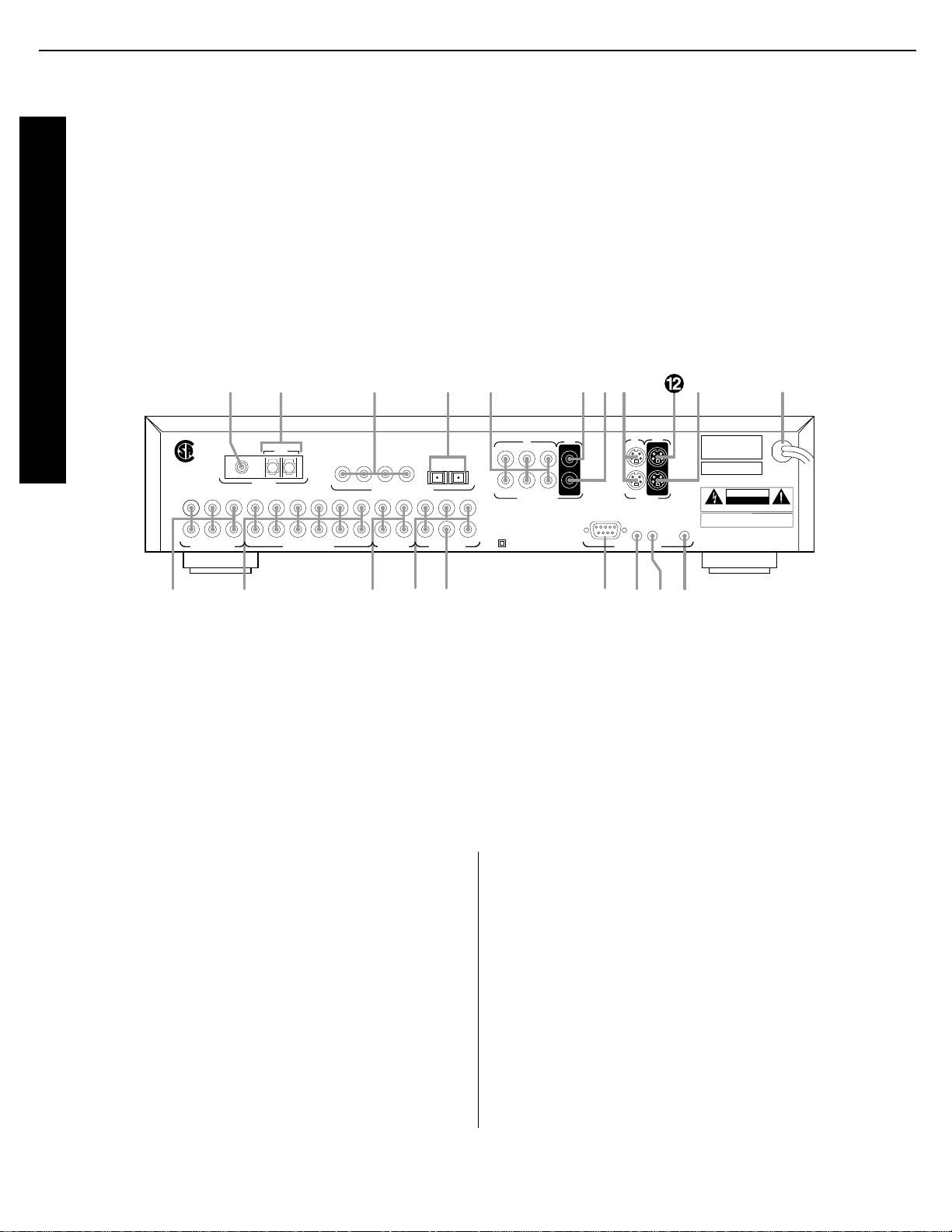
¡ 6-CH Direct Inputs:
Use these inputs for
connections to optional, external audio adapters. To
select a device connected to these jacks, the audio input
for a source must be changed to “6-CH Direct” using the
Source Menu
(see figure OSD-6 on page 29).
™ Analog Audio Inputs:
Connect the output of
analog audio devices to these inputs. Note the left
channel input is on top, and the right channel input is
on the bottom. Once the inputs have been connected
they may be assigned to any of the 2.0’s seven source
positions using the
Source Menu
(see figure
OSD-6 on page 29).
£ Record Outputs:
Each of these two pairs of
jacks carries the identical audio signal, which is the
audio output selected through the
Record Outputs
menu (see figures OSD-35 and OSD-36 on pages 50 and
51). Connect these jacks to the “REC IN” input of a VCR,
cassette recorder, DAT, reel-to-reel recorder, or another
audio recording device.
¢ Main Channel Audio Outputs:
Connect these
jacks to the input of the audio power amplifier. When
making connections to an amplifier make certain that
channels are connected to a matching input on the amp.
(e.g., front left to front left, center to center, etc.).
Rear Panel Connections
IMPORTANT NOTE: Never make or remove any connections to the Signature 2.0 with the Master Power Switch in the
“ON” position. It is also a good practice to make certain that the power amplifiers connected to the 2.0 are also turned
off when making or removing any connections. This eliminates the risk of possible damage to your speakers or other
system components.
When making connections to the Signature 2.0 make certain that the plugs are firmly seated into the jacks. This prevents
intermittent connections which may interfere with performance.
DIGITAL AUDIO DATA INPUTS
ANTENNA
SUB
1 2 3 4 5 6SURRCENTER SURRCENTERFRONT
1 2 3 4
65
32
RS-232
115V
~
60Hz
75 WATTS
IRINIR
OUT
TRIGGER
OUTPUT
FM AM
ANALOG AUDIO INPUTS
AUDIO OUTPUTS
REC OUTPUTS6-CH DIRECT INPUTS
EXTERNAL CONTROLS
L
R
L
R
FRONT
1
1
Confidential Unpublished Works ©1992-1997 Dolby Laboratories.
All Rights reserved.
DTS and DTS Surround are trademarks of Digital Theater Systems.
SERIAL NUMBER
MODEL NO.: SIGNATURE SERIES 2.0
HARMAN KARDON
NORTHRIDGE
CALIFORNIA, USA
MADE IN USA
AVIS: RISQUE DE CHOC ELECTRIQUE - NE PAS OUVRIR
CAUTIONCAUTION
RISK OF ELECTRIC SHOCK
DO NOT OPEN
WARNING:
TO REDUCE THE RISK OF FIRE
OR ELECTRIC SHOCK DO NOT EXPOSE THIS
EQUIPMENT TO RAIN OR MOISTURE.
OUT
MAIN
OUT
IN
MAIN
4
5 6
2
S – VIDEO
COMPOSITE VIDEO
REC
REC
SUB
IN
®
NRTL /C
LR110480
CSA E65
This device complies with part 15 of the FCC Rules. Operation is subject to the following two conditions:
(1) This device may not cause harmful interference, and (2) this device must accept any interference
received, including interference that may cause undesired operation.
Double Insulated – When servicing
use only identical replacement parts.
¡
™ £ ¢ ∞ ¶• ª§
‚⁄‹fi›°
‡ fl·a
6-CH DIRECT INPUTS ANALOG AUDIO INPUTS REC OUTPUTS
EXTERNAL CONTROLS
AUDIO OUTPUTS
SUB
¡ 6-CH Direct Inputs
™ Analog Audio Inputs
£ Record Outputs
¢ Main Channel Audio Outputs
∞ Subwoofer Output
§ RS-232 Control Port
¶ IR Input
• IR Output
ª Trigger Output
‚ AC Power Cord
⁄ S-Video Record Output
¤ S-Video Main Output
‹ S-Video Inputs
› Composite Video Record Output
fi Composite Video Main Output
fl Composite Video Inputs
‡ Optical Digital Audio Inputs
° Coax Digital Audio Inputs
· AM Antenna Input
a FM Antenna Input
15
Signature 2.0 Processor/Tuner harman/kardon
Page 16

Rear Panel Connections
11
Signature 2.0
∞ Subwoofer Output
Connect this jack to the
line level mono input of an optional powered subwoofer, or the audio input of an external amplifier used
to drive a passive subwoofer. If you are using a passive
subwoofer that has both left and right inputs and no
indication of which to use for mono subwoofer inputs,
it is advisable that a “Y” cable be used so that the signal
is fed to both inputs.
§ RS-232 Control Port:
This jack is provided to
permit operation of the Signature 2.0 by computers or
home automation systems. The use of this control port
requires additional optional software and it is strongly
recommended that a Harman Kardon dealer be consulted
before any connections are made.
¶ IR Input:
If the 2.0’s front panel IR sensor is blocked
due to cabinet doors or other obstructions, an external IR
sensor may be used. Connect the output of the sensor to
this jack.
• IR Output:
This jack may be connected to other
compatible Harman Kardon products so that they
will receive infrared commands captured by the 2.0’s
remote sensor.
ª Trigger Output:
If a compatible Signature Series or
Harman Kardon audio power amplifier will be used with
the 2.0, connect the amplifier connection cable supplied
with the 2.0 between this jack and the “Trigger Input” of
the amplifier. When connected by a properly trained
dealer or installer, this output may also be used to control
other devices designed to accept a 6- to 12-volt “Power
On” trigger signal, such as projection television screens or
automatic blinds. The MAXIMUM current draw for all
circuits connected to this output is 150 milliamperes.
‚ AC Power Cord:
Connect this plug to an
unswitched, wall-mounted AC outlet.
⁄ S-Video Record Output:
Connect this jack to the
S-Video “REC-IN” input of a VCR.
¤ S-Video Main Output:
Connect this jack to the
S-Video input of the TV, video monitor, projector or
display that will be used to view the On-Screen Control
Menus of the 2.0 along with any selected S-Video input.
‹ S-Video Inputs:
Connect the output of S-Video
sources to these input jacks. Once the inputs have been
connected they may be assigned to any of the 2.0’s seven
source positions using the
Source Menu
(see figure
OSD-5 on page 27).
› Composite Video Record Output:
Connect this
jack to the composite video “REC-IN” input of a VCR.
fi Composite Video Main Output:
Connect this
jack to the composite video input of a TV set, video
monitor, projection television or other video display
device that will be used to view the On-Screen Control
Menus of the 2.0 along with the selected video input.
fl Composite Video Inputs:
Connect the output of
composite video sources to these input jacks. Once the
inputs have been connected they may be assigned to any
of the 2.0’s source positions using the
Source Menu
(see figure OSD-5 on page 27).
‡ Optical Digital Audio Inputs:
Connect the
Optical (TosLink) digital audio output of audio sources
to these jacks. Once the inputs have been connected
they may be assigned to any of the 2.0’s source
positions using the
Source Menu
(see figure
OSD-5 on page 27).
° Coax Digital Audio Inputs:
Connect the coax
digital audio output of audio sources to these jacks. Once
the inputs have been connected they may be assigned to
any of the 2.0’s source positions using the
Source
Menu
(see figure OSD-5 on page 27).
· AM Antenna Input:
Connect the AM loop antenna
supplied with the 2.0 to these terminals. An external AM
antenna may also be connected here.
a FM Antenna Input:
Connect an FM antenna
to these terminals. Note that the supplied 300-ohm to
75-ohm adapter is required for connections from twinlead dipole antennas.
16
Signature 2.0 Processor/Tuner harman/kardon
Page 17
Remote Control Operation
12
Signature 2.0
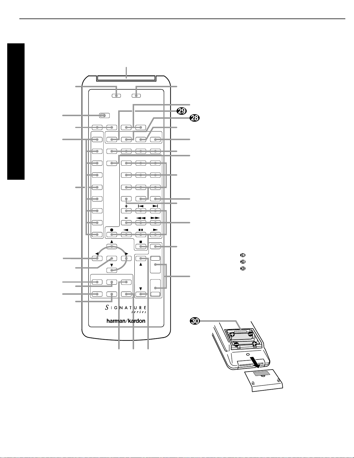
Use Learn
TV
Vid 1
Mono
+
Display
Music Movies Stereo
1 2 3
4 5 6
7 8 9
Disc/Track
0 Enter
Store RDS Type
Source
Off
SourceOnMain
Off
Main
On
Presets
Vid 2
Vid 3
Simul
Tuner
CD
Tape
Aux
Menu
Treble
Bass
Center
Surr
Volume
Mute
TV
Volume
Sending Learning
Balance
Sub
i
j
b
c
d
f
g
h
e
k
l
n
p qo
m
r
s
t
u
v
w
x
y
z
`
Presets
a
a Main Power On/Off
b Learn LED
c IR Transmitters
d Sending LED
e Use/Learn Switch
f Source Power On/Off
g Source Selection
h Simulcast Button
i Menu Control Buttons
j Menu Button
k Treble Cut
l Subwoofer Trim
m Bass Boost
n Balance Control
o Center Mode
p Surround Control
q TV Volume
r Main Volume Controls
s Mute
t Transport Controls
u Disc/Track
v Enter
w Numeric Keys
x Display
y Surround Mode Selectors
z Preset Tuning
` RDS Type Search
RDS ID/Text
Store
Battery Compartment
Remote Control Operation
17
Signature 2.0 Processor/Tuner harman/kardon
Page 18

Remote Control Operation
13
Signature 2.0
Although the basic functions of the Signature 2.0 may
be operated from the front panel, most operation will
be controlled through the wireless remote. The remote
is a powerful tool, and it is worth taking a few minutes
to familiarize yourself with the interaction of the various
controls. In addition to the functions listed below, the
2.0’s remote may be programmed to operate most
infrared controlled products on the market. For complete
information on how to program the remote, read
pages 17-18.
a Main Power On/Off:
Press these buttons to turn
the 2.0 on or to place it in the standby mode.
NOTE: The
Master Power Switch1
must be in the
“ON” position for these, or any other buttons on the
remote to operate any function on the 2.0.
b Learn LED:
This indicator will illuminate when
a button on the remote is being programmed with
signals from another remote during the “learning” mode.
The light will go out when the signal is received
and memorized.
c IR Transmitters:
Behind this translucent panel
are the infrared transmitters that send signals from the
remote unit to the 2.0. When pressing buttons to issue
commands, point this area towards the 2.0.
d Sending LED:
This indicator should flash any
time a button is pressed to confirm that a command is
being sent to the receiver of another unit. If the light is
dim or does not illuminate when a button is pressed the
batteries in the remote should be replaced.
e Use/Learn Switch:
This switch selects the
operation mode of the remote control. Slide it to the
left for normal operation. Slide it to the right when the
remote is being programmed.
f Source Power On/Off:
Pressing these buttons
will send a turn-on, turn-off command to the source
device last accessed by pressing one of the
Source
Selection
buttons
g. Note that these commands
may require programming of the remote control as
explained on pages 17-18.
g Source Selection:
Pressing these buttons will
select the input source for the 2.0. It will also activate the
transport and numeric control buttons associated with
that device, enabling control of the source with the
2.0 remote. If the 2.0 is in the Standby mode when one
of these buttons is pressed, the unit will automatically
turn on and switch to the selected input.
h Simulcast Button:
Using this button enables you
to listen to one source while you watch the video from
another. To use the Simulcast feature, first press the
Source Selection
button gfor the desired video
source, followed immediately by pressing this button.
Release the
Simulcast
button, and press the desired
audio source within 5 seconds.
i Menu Control Buttons:
These buttons control
the location of the on-screen cursor to select items from
on-screen menus, and they also act to select, move,
increase or decrease items from control functions. The
›
button is often used to move from a main menu to
a sub-menu, the ‹and ›buttons are used to select
choices within menus, and the ⁄and¤buttons are
used to move up and down through lists of selections.
j Menu Button:
This button is used to activate the
On-Screen Menu Control System when it is not being
used, or to enter selections and exit from the control
system when it is active.
k Treble Cut:
Press this button to activate the Treble
Cut feature. When the button is pressed a menu will
appear on the screen (see figure OSD-19 on page 42), and
you may reduce the high-frequency level of the output
by pressing the ‹or
› Menu Control
buttons i.
When you have completed the adjustment, press this
button again to enter the setting and remove the menu
from the screen.
l Subwoofer Trim:
Press this button to activate
the Subwoofer Trim feature. When the button is pressed
a menu will appear on the screen (see figure OSD-21
on page 42) and you may adjust the subwoofer output
volume by pressing the ‹or
› Menu Control
buttons i. When you have completed the adjustment,
press this button again to enter the setting and remove
the menu from the screen.
18
Signature 2.0 Processor/Tuner harman/kardon
Page 19

Remote Control Operation
14
Signature 2.0
m Bass Boost:
Press this button to activate the Bass
Boost feature. When the button is pressed a menu will
appear on the screen (see figure OSD-20 on page 42)
and you may adjust the subwoofer output volume by
pressing the ‹or
› Menu Control
buttons i. When
you have completed the adjustment, press this button
again to enter the setting and remove the menu from
the screen.
n Balance Control:
Press this button to activate the
Balance Control feature. When the button is pressed a
diagram will appear on the screen (see figure OSD-9
on page 32) that shows a small circle as the current
listening position. To adjust the front/back fade and
left/right balance use all four
Menu Control
buttons
i
to “move” the listening position with respect to the
center of the room. Press this button again to enter the
setting and remove the diagram from the screen.
o Center Mode:
Press this button to select the
center mode. When the button is pressed a menu will
appear on the screen (see figure OSD-22 on page 43)
and you may then make a selection using the ‹or
›
Menu Control
buttons i. Press the button again to
enter the setting and remove the menu from the screen.
p Surround Control:
Press this button to turn the
surround channel output off or on. When the button is
pressed a menu will appear on the screen (see figure
OSD-23 on page 43) and you may then make a selection
using the ‹or
› Menu Control
buttons i. Turning
the surround channel feed off with this control will
change the setting only until the source is changed, at
which point the setup configuration selected in the
Spkr Setup Menu
will take effect. Press the
button again to enter the setting and remove the menu
from the screen.
IMPORTANT NOTE: Adjustments made using
the
Treble Cut, Subwoofer Trim, Bass Boost
,
Balance Control, Center Mode
and
Surround
Control
buttons
k l m n o p
are
temporary. When the mode or input source is changed,
or the 2.0 is turned off, the adjustment is canceled and
the system preset will return. To make a permanent
change to any of these settings, use the
Effects
Menu
, as described starting on page 30.
q TV Volume:
These buttons may be used to control
the volume of a TV, set-top converter box or other audio
device not connected to the 2.0. When shipped from the
factory, the buttons will control television sets with the
popular RC-5 remote code system. To use these buttons
to control other television sets you must program the
codes into the remote as described on page 37.
r Main Volume Control:
These buttons control the
unit’s volume. Note that all channels are controlled
simultaneously.
s Mute:
Press this button to temporarily silence the
audio output of the receiver. Press it again to return to
the previous volume level.
t Transport Controls:
These buttons may be
programmed to control the transport functions of
compatible VCR’s, DVD player, CD player, cassette
decks, and other source equipment by following the
instructions on pages 17 and 18. As shipped from the
factory, the remote will control compatible Harman
Kardon CD players and cassette decks when the
CD
or
Tape Source Selection
buttons ghave been
pressed. Some of these buttons also have specific
functions to operate the 2.0’s tuner when it is selected.
a) The ‡ and· buttons are used for seek tuning.
Each press of these buttons will cause the tuner
to search for the station with the next higher or
lower frequency that has a signal strong enough for
acceptable reception.
b) The
‚
and
—
buttons may be used to
manually tune stations in single frequency increments
or, by pressing and holding one of these buttons, it is
possible to quickly tune to a specific station.
u Disk/Track:
When a compatible Harman Kardon
CD player or cassette deck is in use, this button has
different functions. It may also be re-programmed to any
compatible IR code function following the instructions
on page 18.
a) When CDis selected and the unit is a CD changer,
these buttons will change to the next disc ∏or
previous disc Â.
19
Signature 2.0 Processor/Tuner harman/kardon
Page 20

Remote Control Operation
15
Signature 2.0
b) When
Tape 1
is the input source, and the tape
machine is a compatible Harman Kardon dual cassette
deck, these buttons will switch between the “A” and
“B” wells.
v Enter:
Press this button to select a station after
you have entered its frequency or preset location using
the
Numeric Keys w
.
w Numeric Keys:
When the 2.0’s tuner is in use,
press these buttons to access a radio station’s frequency
or to enter a station to a specific preset location. See page
46 for complete information on tuning stations and programming preset memories. When other inputs are in use
these keys may be programmed to use with TV, CD, and
VCR functions that require numeric inputs. When
shipped from the factory, the remote is programmed
with the RC-5 control codes that activate many popular
brands. It may also be re-programmed for use with most
compatible infrared control systems by following the
instructions on page 17.
x Display:
Press this button to show the details of the
current input source via the On-Screen Display System.
When a digital input is in use, the comprehensive display
(see figure OSD-26 on page 44) will also show information
when Dolby Digital sources are being decoded. Press it
again to remove the display from the screen.
y Surround Mode Selectors:
Press these buttons
to select a Surround mode for the current listening
session. Note that the selection of available modes will
change based on the use of an analog or digital input.
a) Pressing the
Mono +
button will switch between
the current surround mode and mono enhancement
circuits that create an enveloping soundfield from a
mono input.
b) Pressing the
Music
button will scroll through the
list of surround modes that are most appropriate to
musical selections.
c) Pressing the
Movies
button will scroll through the
list of surround modes that are most appropriate for
movie soundtracks.
d) Pressing the
Stereo
button will switch between pure
two-channel stereo sound and the previously selected
surround mode.
IMPORTANT NOTE: Using these buttons will change
the surround mode for a current listening session only.
Once the input source is changed, the 2.0 will revert
to the surround mode that has been entered using the
Source Menu
. To permanently change the surround
mode that is assigned to an input source, use the Source
Menu as described on page 28.
z Preset Tuning:
Pressing this button when the
tuner is active to scroll up through the list of stations
entered into the preset memory.
` RDS Type Search:
When the FM tuner is active,
press this button to initiate a search for a station with
a specific program type. For more information on RDS
tuning, see page 48.
RDS:
When the 2.0 is tuned to an FM station
that is transmitting RDS data, press this button once to
display the station’s
Text
message. Press it again to
view information that the station is transmitting about
the station’s call letters, network affiliation or other
identifying information, as well as the station’s program
type (PTY). See page 48 for complete information on
using the RDS system.
Store:
When the tuner is in use, press this
button to enter a station into the preset memory after
selecting a location number between 1 and 30 using
the
Numeric Keys w
.
Battery Compartment:
Insert fresh AAA
batteries here, being certain to observe proper polarity
by matching the (∏) and (Â) indications on both the
batteries and case. To remove the cover press down
slightly on the raised ridges and gently push the cover
away from you. To replace the cover, slide it back
towards you until you hear the latch click.
20
Signature 2.0 Processor/Tuner harman/kardon
Page 21

Troubleshooting Guide
54
Signature 2.0
Troubleshooting Guide
The Signature 2.0 is designed for trouble-free operation.
In normal use, most users will not encounter any trouble
with the unit. However, as with any sophisticated
electronic device, there may be occasional problems on
initial installation or during the life of the unit. The items
described on this page and in the table below are a brief
guide to the minor problems that you may be able to
correct yourself, and to certain anomalies that result from
outside conditions.
If these solutions do not rectify a problem, or if the
problem persists, contact your dealer or installer.
Problems may also be solved by an authorized Harman
Kardon Service Center. To locate the Service Center
nearest you, call (800) 422-8027 toll free in the United
States. Harman Kardon may be contacted via the Internet
at www.harmankardon.com
Error Messages
When the surround mode name blinks in the front panel
Information Display
(Figure FPD-12) that is your
indication that there is a mismatch between the input
source and the surround mode, or that there is no digital
input at all.
Mode Mismatch
Certain modes are digital only, while others operate with
analog signals only. The blinking light is an indication of
a source/mode mismatch.
When this condition exists, the 2.0 will automatically
select a properly matched surround mode and continue
normal operation. To view the name of the mode
selected, press the
Display
button x. The correct
mode will be displayed next to the
Alt Mode
indication (Figure OSD-27). To stop the flashing
message, press the appropriate
Surround Mode
Selector y 4
until the correct mode is selected.
No Data
If the mode name flashes when the mode and input are
matched, this is an indication that the 2.0 is not receiving
digital data from the source machine. This will typically
occur when a DVD player is in pause or a fast scan
mode, as no digital data is typically output unless the
disc is playing. To confirm that the lack of data is the
cause of the error message, press the
Display
button
x
and check the on-screen status screen. If a
NO
AC-3 Info
message appears (Figures OSD-14/
OSD-18/OSD-27), this is your indication that the player
is not sending a digital signal. Put the unit into Play,
check the digital input connections or check to see that
a digital input is selected to solve this problem.
Digital Noise With DVD Players
Certain early models of DVD players may occasionally
cause a sharp “crack” or “snap” in the output channels
during track or chapter changes. This is caused by a
momentary discontinuity in the digital data output
which is not long enough to trigger the flashing error
message, but long enough to disrupt the processor. This
type of random noise is caused by the DVD player, and
it does not indicate a problem with the 2.0.
System Reset
In rare cases where the 2.0’s operation or the displays
seem abnormal, the cause may be erratic operation of the
system’s memory or microprocessor.
The first step to correct this problem is to turn the 2.0
off using the
Master Power Switch1
and unplug
the unit from the AC wall outlet and wait at least
three minutes. After the pause, reconnect the AC power
cord and turn the unit on again. If the system still
malfunctions, a system reset may clear the problem.
Note that clearing the system memory may correct the
problem, but will also erase all system configuration
data, input source assignments, input profile names,
effects level settings and tuner preset memories. It is
always a good idea to record your system configuration
information in the Worksheets in Appendix B, if possible,
before resetting the system. To reset the system, press
the
Menu
button jto view the
Setup Menu
. Press
the
¤ Menu Control
button iuntil
Advanced
Setup >
is highlighted. Press the
› Menu
Control
button ito go to the next screen.
21
Signature 2.0 Processor/Tuner harman/kardon
Page 22
Troubleshooting Guide
55
Signature 2.0
At the
Advanced Settings
menu (Figure
OSD-10), press the
¤ Menu Control
button
i
twice until
SYSTEM RESET >
is highlighted.
Press the
› Menu Control
button iagain.
This will bring up the
System Reset Menu
(Figure OSD-40). If you wish to exit at this point, press
the
Menu
button j. To proceed with the r eset, press the
¤ Menu Control
button ito move the highlighted
area to the
Yes >
line, and then press the
› Menu Control
button i.
Figure OSD-40
The next screen (Figure OSD-41) instructs you to proceed
by pressing and HOLDING the
Store
button until
the reset is complete.
Figure OSD-41
Press and hold STORE
to accomplish RESET
System Reset Menu
NO!
Yes >
!!! WARNING !!!
ALL SETTINGS WILL BE
LOST !!
ARE YOU SURE?
Follow that instruction by holding the
Store
button
until the
Reset Completed
message appears
briefly on screen (Figure OSD-42) and the front panel
Information Display
. This is your indication that the
reset has been accomplished, and you may release the
Store
button. The system will automatically return to
the Advanced Settings menu.
Figure OSD-42
After a reset the system is returned to the original factory
default settings as shown in Appendix A, and the microprocessor system is re-initialized. Press the
Menu
button
j
twice to return to normal operation, but remember
that you will have to re-enter any settings previously established that differ from the factory presets.
If a reset does not solve the system problem, consult an
authorized Harman Kardon service depot.
Reset Completed
22
Signature 2.0 Processor/Tuner harman/kardon
Page 23

Troubleshooting Guide
56
Signature 2.0
Symptom
Unit does not operate
when standby switch or
remote power is pressed.
Display lights, but no
sound is heard from
any channel.
Unit does not respond
to remote commands.
Intermittent buzzing
in tuner.
Status Menus visible,
but setup menus
do not appear.
Amplifier connected to
the trigger output cycles
on and off.
Audio signals distort for
analog inputs.
Solution
•
Make certain AC power cord is plugged into a
live outlet.
•
Check to see if AC outlet is switch controlled.
•
Turn on Main Power Switch.
•
Make certain connections to source equipment and
amplifiers are secure.
•
Turn Volume control or press Mute button.
•
Turn Amplifier on and/or check trigger connections.
•
Change both remote batteries.
•
Slide Use/Learn switch to Use.
•
Make certain front panel sensor is visible.
•
Move unit or antenna away from computers, fluorescent lights, TVs, motors or other electrical appliances.
•
Switch to input with video signal present.
•
Viewing the front panel display, use the menu
system to reach
Display Options
, under
the
Advanced Settings
menu. Switch the
“
Menu Bkgrnd
” to “
Blue
” (see page 36).
•
Make certain that the jack used is a 1⁄8² (3.5mm)
MONO miniplug, not a stereo plug.
•
Check to see that the plugs are firmly seated on
both ends.
•
Adjust input level to proper reference (see page 29).
Possible Cause
•
No AC Power.
•
Main Power Switch Off.
•
Intermittent Connections.
•
Mute is engaged.
•
Amplifier is off.
•
Weak batteries in remote.
•
Remote is in Learn position.
•
Remote sensor is obscured.
•
Local interference.
•
Menu background set to
“video” but no video is
present.
•
Connection problems.
•
Input level too high.
Troubleshooting Chart
23
Signature 2.0 Processor/Tuner harman/kardon
Page 24
Appendix C
64
Signature 2.0
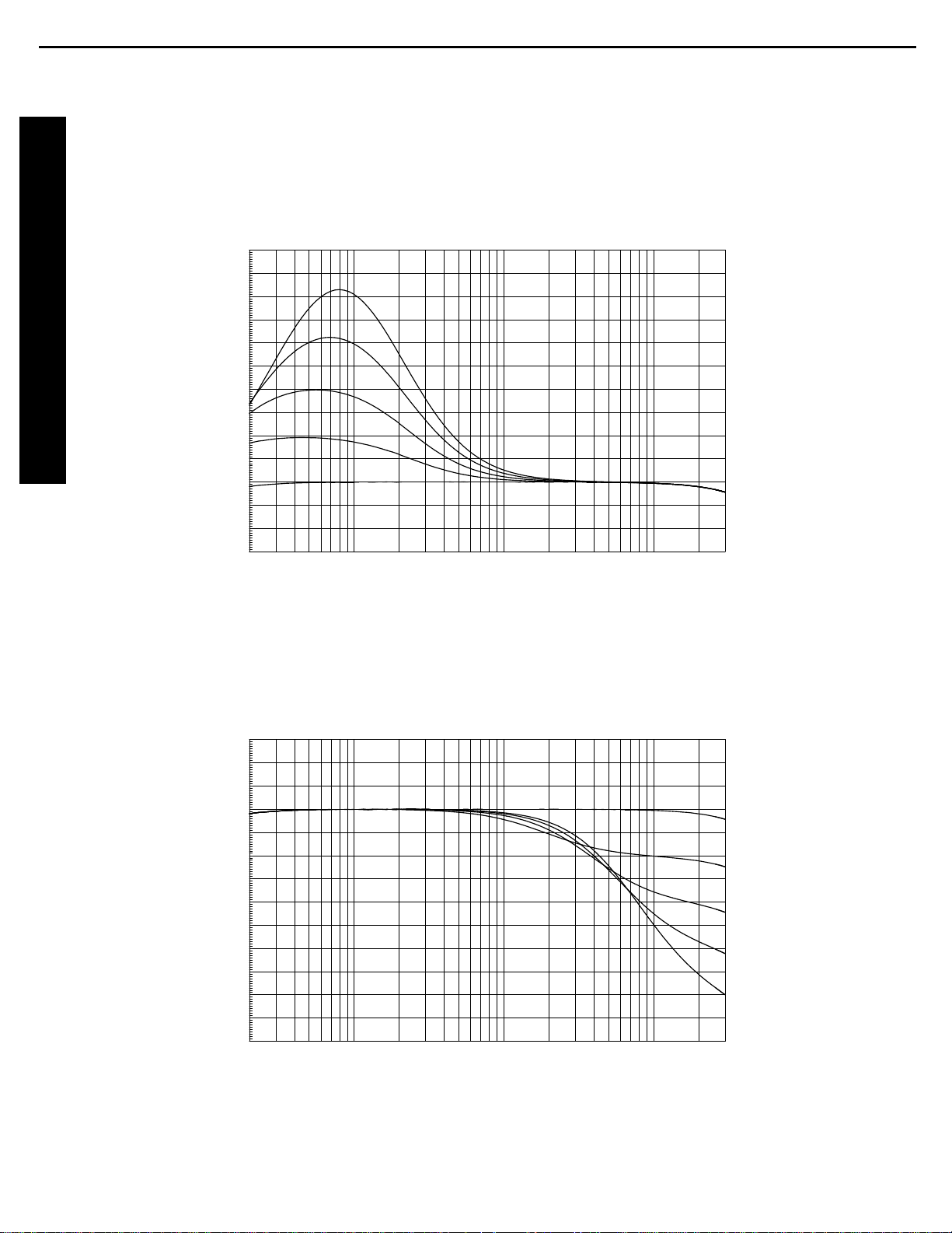
Bass Boost
This chart, using data from a sample Signature 2.0 unit and automated test equipment, shows the frequencies at which
low-frequency information is boosted when settings are changed with the
Bass Boost
control m, or through the use
of the
Effects Menu
(Figure OSD-8).
-3
+10
-2
-1
+0
+1
+2
+3
+4
+5
+6
+7
+8
+9
20 30k50 100 200 500 1k 2k 5k 10k 20k
+8
+6
+4
+2
+0
Hz
d
B
r
A
Treble Cut
This chart, using data from a sample Signature 2.0 unit and automated test equipment, shows the frequencies at which
high-frequency information is rolled off when settings are changed with the
Treble Cut
control k, or through the use
of the
Effects Menu
(Figure OSD-8).
-10
+3
-9
-8
-7
-6
-5
-4
-3
-2
-1
-0
+1
+2
20 30k50 100 200 500 1k 2k 5k 10k 20k
-0
-2
-4
-6
-8
Hz
d
B
r
A
24
Signature 2.0 Processor/Tuner harman/kardon
Page 25
25
harman/kardon
Page 26
26
harman/kardon
Page 27
27
harman/kardon
Page 28
28
harman/kardon
Page 29
29
harman/kardon
Page 30

harman/kardon Service Bulletin
30
Service bulletin # H/K2000-07 July 2000 Warranty labor rate: MINOR repair
To: All harman/kardon Service Centers
Models: Signature 2.0 Processor/Tuner
Subject: Remote Control Works Intermittently
In the event you receive a Signature 2.0 with the complaint of “the remote control only works at
certain angles, or when it’s very close to the unit,” perform the necessary steps listed below:
1. Make sure there are fresh batteries in the remote, and they are installed correctly.
2. Question for customer: Are you sure the area between the remote control and receiver is not
blocked by some object, and the distance is no more than 15 feet, at an angle no greater than 30°
from the front of the receiver ?
3. Question for customer: Are you sure strong lighting is not being directed towards the IR sensor of
the unit ?
If the remote control of the Signature 2.0 Processor/Tuner still does not function correctly under
proper conditions, then verify that the position of the IR sensor located behind the Signature 2.0
front panel is correct, as per steps below.
4. Remove the top cover to the unit (10 Phillips screws).
5. In the front left corner, carefully unplug the two colored female connectors on the Power Switch PCB.
6. Remove the (5) Phillips screws holding the front panel onto the chassis; there is one screw on either
side, and three bottom screws.
7. Carefully disengage the front panel from the chassis; you may now remove the four plated Phillips
screws deep in the recesses of the stamped metal cover plate at the rear of the front panel. A
magnetic screwdriver bit is recommended.
8. Disengage rear cover from the front panel; you should now see the rectangular IR sensor at the left
side of the VLF display. Align and straighten the sensor as indicated below; it should be straight and
parallel in relation to the front panel; the rounded lens should be pointed straight forward.
9. Replace all screws and reassemble, following the instructions in reverse order; be sure and replace
the two power switch connectors.
10. Connect all cables necessary for proper operation; power up the unit and check that the remote
control is working properly.
harman/kardon Incorporated 250 Crossways Park Drive, Woodbury New York 11797 (516) 496-3400
Page 31

harman/kardon Service Bulletin
31
Service bulletin # H/K9709 Dec. 1997 Repair rate does not apply
To: All harman/kardon Service Centers
Models: Signature 2.0 Processor/Tuner
Subject: Turn on/ turn off “thump”
In the event you receive a Signature 2.0 that is being used with a power amplifier other than the
Signature 2.1 which exhibits a “thump” when the unit is turned ON or OFF:
When a power amplifier other than the Signature Series 2.1 is used with the Signature Series 2.0
Processor/Tuner, you may experience a mild turn-on or turn-off “thump”. The Signature 2.1 power
amplifier has a delay circuit that prevents this from happening.
There was a running change made by the factory that will prevent this symptom using any power
amplifier. The change was made starting with the serial numbers listed below:
Model Serial number
120V
Signature 2.0 GT0003-01001
to
GT0003-02162
Signature 2.0 GT0003-02163
and above
Serial number
230V
GT0006-01001
to
GT0006-01157
GT0006-01158
and above
Status Action
Mild turn-on
or turn-off “thump”
when not using 2.1
Factory Installed
Modification
Call for factory
replacement of
unit under warranty
NONE REQUIRED
To replace a unit under these conditions, please contact harman/kardon to obtain a unit for
exchange in the latest serial number range listed above.
harman/kardon Incorporated 250 Crossways Park Drive, Woodbury New York 11797 (516) 496-3400
Page 32

32
harman/kardon Service Bulletin
Service bulletin # H/K9708 Dec. 1997 This is considered a Major Repair
To: All harman/kardon Service Centers
Models: Signature 2.0 Processor/Tuner
Subject: Complaints related to version 2.0 - 2.3 Software
In the event you receive a Signature 2.0 with one or more of the symptoms listed below, upgrade the
software to revision 2.4. Page 2 of this bulletin provides replacement instructions for IC U305.
Confirmation: Immediately after Power ON, the displays indicates the software revision. If the display
indicates a Rev number less than 2.4 (i.e. rev. 2.0 or 2.3) then replace IC U305.
Note: Internally, IC U305 will be marked with a l abel reading 1.0 (A misprint – it’s actually 2.0), 2.0 or 2.3.
SYMPTOMS APPLICABLE TO VERSION 2.0 ONLY:
• When a mode other t han S tereo is selected, and the system is m uted, adjusti ng the volume will not UNMUTE the
system.
• “VOL” t ext erroneously c ontinues to be displayed when di r ec t tuner fr equenc y ac c ess is used.
• Dolby Di gital Mono is erroneously selectable from the fr ont panel buttons when an analog source i s selec ted.
• Display flashes source/volume information when it ems are changed in the tuner menu.
• When a preset is selected from t he tuner menu, the manual RDS items are enabl ed/disabled inc or r ec tly based on the
band of the selec ted preset (i.e. AM stations shouldn’t get manual RDS ID and Type).
• When switching between 2 input s i n ster eo mode, one analog and the other digi tal, the sound i s muted erroneously
(however, c hanging modes will seem to restore the sound).
• Remote S eek Up and S eek Down butt ons do not work in tuner menu for frequency selection.
• There is an erroneous l evel boost when switchi ng into 6-ch di r ec t mode.
• When switching f rom Stereo mode to 6-ch direct m ode, the Center and Surround speaker s remain m uted, as though still
in Stereo.
• Tuning in Long Wave i n E ur opean setup is in 9kHz inc r ements, as opposed to the correc t 1kHz increments; not Nort h
America.
• When exit ing the 6-Ch dir ec t Audio input , the mode err oneousl y stay s in 6-Ch Direct mode. (i .e. when going fr om 6-Ch
Direct input to Anal og #1 input, the mode stays in 6-Ch Dir ec t…which is wrong. Note the difference between Audio input
and mode).
• In the Speaker S etup menu, when switching sel ec ted speakers from on to off, or vice versa, those speaker outputs are
not im mediately muted (i.e. sound continues to come from t he Center speaker, even though the user just c hanged the
menu it em to read “Cent er : None”.)
• OSD timeout value allows a value of 00 which never times out.
• When selecting a source, the unit may not select the correct i nput level value.
• “Sensitive” remot e button problem when cycling through the sources/m odes from the menuing system . (e.g. one button
press results in two v alue changes; hit the button once and you j ump fr om Analog 2 to A nalog 4).
• “High” indicator ( si gnal level input) on the display from some CD players, some tracks, with subsequent distortion.
SYMPTOMS APPLICABLE TO VERSION 2.3 ONLY:
• Random charac ters are generated at the bottom-r ight of the video output.
• Center channel “ B oost” function doesn’t boost the Center channel sound level.
• “Sensitive” remot e button problem when cycl ing through the Center/ S urround effects. (e.g. one button press results in
two val ue c hanges).
Model Serial number
120V
Signature 2. 0 GT0003-01001
to
GT0003-02162
Signature 2. 0 GT0003-02163
and above
Serial number
230V
GT0006-01001
to
GT0006-01157
GT0006-01158
and above
Status Action
Has early software
versi on 2.0 or 2.3
h/k part# A003-0020-4
Factory I nst alled
versi on 2.4
NONE REQUIRE D
Replace IC U305
with v ersion 2.4
1
Page 33

33
Signature 2.0 Processor/Tuner harman/kardon
2
SIGNATURE series 2.0
Software (IC U305) Replacement Instructions
Before replacing the software in the SIGNATURE 2.0 Processor, confirm the Software revision in the unit. To
check, plug the unit in and turn it ON. The display will read “Ver __.__”. Make sure the version you are
replacing is a higher number than what’s on the display.
CAUTION: IC U305 EPROM IS AN ELECTROSTATICALLY SENSITIVE DEVICE AND CAN BE DAMAGED
BY CARELESS HANDLING; YOU MUST FOLLOW PROPER STATIC CONTROL PROCEDURES TO
PREVENT DAMAGE TO THE DEVICE.
1. Confirm the unit is unplugged and OFF.
2. Remove the 7 top cover screws. There are 2 on each side and 3 on the upper portion of the back panel.
3. Remove the top cover; slide it towards the back of the unit about an inch and lift it off from the back first.
4. Locate the video board directly behind the video jacks. Unplug the ribbon cable marked “CONTROL” on the
circuit board under the ribbon. Unplug the green power supply cable marked “PWR”; apply only upward
force to remove it.
5. Locate and remove the (4) screws and (1) nut holding the video board on. Two screws are located between
the “COMPOSITE VIDEO” RCA jacks on the back panel. Two screws, with washers, are located on either
lower side of the “S VIDEO” jacks on the back panel. The (1) nut is located on the inside corner of the
printed circuit board next to capacitor C504.
6. Remove the video board by lifting the edge of the circuit board that has the connectors on it (CONTROL
and PWR) up and out of the way of the power supply capacitors before complete removal.
7. The software IC (U305) should be visible at this point. Find it on the CPU circuit board under the video
board, plugged into a 32 pin IC socket marked U305. You may need to move the 10 conductor ribbon cable
aside to read the locator number; there is also a label on the IC stating the software version. (On one side
of the IC there is a ribbon connector, on the other side of the IC is another device - MS6264L).
8. Apply a “L” shaped pick or jewelers flat blade screwdriver between the IC (U305) and socket at the notched
end. Pry the end of the IC up enough to grab it and carefully lift straight up without further bending the pins
while you complete the extraction.
9. Test fit the new IC (h/k part# A003-0020-4). The legs usually need to be bent inward. Do this by placing
one side of the IC legs against the edge of a table to bend all of them at the same time. Do this on both
sides just enough for the IC to fit properly into the socket.
10. Position the IC so the notch faces towards the transformers. Line up the legs into the socket and press
down hard enough to seat the IC into the socket. Look at the legs on both sides of the IC and make sure
there are not bent or misaligned.
11. Reinstall the video board in the same manner it was removed as in step 5, and reinstall the screws in their
respective locations.
12. Plug the ribbon cable into the connector marked “CONTROL” and the green power cable into the connector
marked “PW R”.
13. Replace the top cover in the same manner it was removed in step 2, and reinstall the 7 screws. Tighten
the rear panel screws first.
14. You must do a reset for the new software to be enabled. Make sure the On/Off button is in the OFF
position . Plug the unit into an AC ou tlet. While pressing the SOURCE and MUTE buttons down at the same
time, turn the On/Off button to the ON position. At this moment, the lower line of the display must read
“Initialized”. You may then release the buttons.
Page 34

harman/kardon Service Bulletin
34
Service bulletin # H/K9904 October 1999 Warranty labor rate: MINOR repair
To: All harman/kardon Service Centers
Models: Signature 2.0
Subject: DTS Upgrade
The following instructions detail the steps needed to upgrade a Harman Kardon Signature Series 2.0
Processor/Tuner with a new DSP board and operating system EEPROM. These additions will provide significant
improvements in performance, with the following major new advantages:
· Greatly improved audio decoding in all modes, using the highly regarded Crystal Semiconductor, CS4926,
audio-decoding circuit.
· DTS processing, along with Dolby Digital, Dolby Pro Logic, and a wide variety of music and movie surround
modes.
· Easier programming when used with computer-controlled RS-232 remote systems.
· Faster microprocessor operation for quicker response to remote commands
· Improved and updated on-screen menus with added features.
1) Order h/k DTS Upgrade kit, part number: SIG2.0 DTS UPGRADE.
2) A new Owner’s manual (h/k part # HA160-0004-Arev1) should be ordered for the 2.0 that covers the
operation of the DTS upgrade.
3) Following the detailed instructions on the following page.
Model Serial number (120V) Serial number (230V) Status Action
Signature 2.0 GT0003-01001
to
GT0003-04000
Signature 2.0 GT0003-04001
and above*
* Additionally, factory modified units have a yellow label on the outer carton stating “Now with DTS”.
GT0006-01001
to
GT0006-02070
GT0006-02071
and above* Changed by factory NONE REQUIRED
Unmodified
Replace IC305,
DSP board
Supplied with
Upgrade kit
Page 35

35
Signature 2.0 Processor/Tuner harman/kardon
Signature 2.0 Upgrade Procedure
WARNING: Please use caution during the removal of the DTS board and EEPROM IC305 from their
protective packages, and during installation. ESD protection is required to assure the parts are not
damaged.
PART I REPLACEMENT OF EEPROM IC305
1. Turn the unit off with the Master Power Switch (on/off button on front panel) and unplug it from the AC
power source; remove any input and output cables.
2. Remove all (10) screws holding the cover on; there are two on the right and left sides, three at the rear, and
three at the top near the front of the unit.
3. Remove the top cover by gently lifting it up slightly from the rear, and then pulling it back away from the unit.
4. Remove the two plated screws to the left and right of the S-Video jacks on the rear panel.
5. Remove the two black screws that are between the yellow video jacks.
6. Inside the unit, the video board is secured at the rear by a metal nut attached to a white plastic post on the
corner of the board. Remove this nut.
7. Lift the video board up slightly, and pull it into the unit. Turn the board upside down and rest it carefully inside
the unit. It is not necessary to unplug any additional connectors.
8. Locate the large EEPROM chip (IC305) on the CPU board that is now visible. The IC is in the center of the
board and has a label with the word “Signature” and a revision number. Note there is a notch in the front
edge.
9. Using an IC Chip Removal & Installation tool (Radio Shack model #276-2101 or equivalent), carefully remove
the IC by gently rocking it from side to side and then pulling straight up.
10. Remove the new EEPROM from the upgrade kit and place it in the socket. When inserting the chip, make
certain that the notched end is facing forward, toward the front of the unit). An outline of the chip with the
notch in the proper position is screened on the board). The new EEPROM will be labeled “2.10a”.
IMPORTANT NOTE: When inserting the new chip, take extra care to ensure all pins are seated in their
respective holes, and they are not bent or damaged before the IC is seated. If needed, use a small flat-blade
screwdriver to gently align the pins into the socket holes.
11. When all the pins are lined up, gently push down on the chip so that it seats firmly in the socket.
12. Replace the video board, pushing the RCA jacks back through the holes in the rear of the chassis and
reseating the hole in the back corner of the board on the plastic support post; replace the nut.
13. Replace the two plated screws and the two black screws that secure the video board to the chassis.
PART II REPLACEMENT OF DSP AUDIO BOARD
14. Remove the plated screw to the right of the optical input jacks (near terminal #6) on the rear panel.
15. Remove the two black screws that are above the digital audio input jacks (#1- 4)
16. Pull the DSP board into the unit, free from the back panel. Remove the white plug at the rear of the board;
then remove the ribbon connectors at either side of the DSP board by gently rocking the connector from side
to side, while carefully pulling each connector upwards.
17. Remove the new DSP board from the upgrade kit. (New DSP boards are » 5 ½” in length; original DSP board
is much shorter). Replace the three connectors; slide the white connector into the header socket on the rear
of the new board. Replace two ribbon connectors back in their sockets on either side of the board. The side of
the ribbon cable with the red line should face towards the front of the unit. Position each connector over the
socket and press into position.
18. Put the new DSP board back into position through the holes in the rear panel.
19. Replace the two black screws above the RCA jacks and the single plated screw.
20. Replace the unit’s cover and (10) screws.
21. Make certain the front panel Master Power On/Off Switch is in the “Off” position; it should extend out
beyond the front panel.
22. To test: Before turning the unit On, it is important that the unit be reset. To reset, first hold in the two outer
buttons on the front panel Source and Mute, then press the Master Power On/Off Switch to the “On”
position; then release the Source and Mute buttons. The front-panel display should now read “Signature
2.0” and “Initialized.” The unit has been reset and is ready for operation.
23. Attach a colored label to the bottom of the unit, and on the outer carton (if available), stating “DTS upgrade”.
Page 36

36
Signature 2.0 Processor/Tuner harman/kardon
The following code changes were made from ver 2.0 to create 2.1 of the
Signature 2.0.
1. When a mode other than Stereo is selected, and the sys tem is muted, adjustin g the
volume will now cause the system to unmute correctly.
2. VOL text is no longer left hanging on the VFD when direct tuner frequency access is
used.
3. Mute timing during power on/off has been adjusted to fit new output muting circuitry.
4. Dolby Digital Mono is no longer selectable from the front panel buttons when an
analog source is selected.
5. VFD no longer flashes source/volume info when items changed from the tuner menu.
6. When a preset is selected from the tuner menu, the ite m s are enabled/d i sabled
correctly based on the band of the selected preset.
7. Speaker trim values have been changed from +10dB –10dB to +10dB –20dB to
compens ate for som e highl y efficient am p /speaker configur ations.
8. OSD, and Volume chip communications sped up.
9. Switching between 2 inputs in stereo mode, one analog and the other digital now
works correctly.
10. Removed long delay in power down sequen ce. This was necessary before the
hardware change to reduce the power off thumping.
11. Ena bl e d Se ek Up and Se ek Dw n buttons in tuner menu for freq uency selection.
12. Updated RDS types to 2.0 spec
13. Removed level boost when switching into 6-ch direct mode
14. Corrected speaker setup problem when switching from Stereo mode to 6-ch direct.
15. US/EURO setup now enabled only from front panel button setup.
The following code changes were made from ver 2.1 to create 2.2 of the Signature
2.0.
1. Tuning in Long Wave in Euro setup is now 1kHz increments (as op posed to 9kHz
increments)
2. When exiting 6-Ch direct, audio mode is now left alone, i. e., if you were in ProLogic
mode when 6-ch direct input was selected, you ’re still in ProLog ic mod e when an
analog or digital input is selected. In version 2.0 and 2.1, the mode was left in the 6Ch direct.
3. In the Speaker Setup menu, when switching selected speakers from on to off, or vice
versa, those speaker outputs are immediately muted.
4. OSD t imeout value now has a value between 1 and 15 seconds. Pre vious ver sions
would allow a value of 00wh ich wou ld never timeout.
5. Bug fixed which, under certain conditions, when selecting a source, would not select
the correct input level value.
The following code changes were made from ver 2.2 to create 2.3 of the Signature
2.0.
1. Fixed problem introduced in version 2.2, which caused the subwoofer to be muted
when Stereo mode was selected.
2. Fixed the “twitchy” button problem when cycling through the sources/modes from the
menuing system.
Page 37

37
Signature 2.0 Processor/Tuner harman/kardon
The following code changes were made from ver 2.3 to create 2.4 of the Signature
2.0.
1. Added changes re quir e d for Rev 3 au di o bo ar d to reduce power transi ti o n
“thumping”.
2. Code change to eliminate random characters at bottom-right of video ou tp ut .
3. Center channel “Boost” function now works correctly.
4. Reduced remote button “twitchyness” when selecting Center/Surround effects.
The following code changes were made from ver 2.4 to create 2.4E of the
Signature 2.0.
1. Fixed record bus problem. Tracking/Selectable now work correctly.
2. Auto mode switching no longer erroneously unmutes.
3. ‘<’ and ‘>’ key in tuner menu now work correctly. Both used to execute ‘>’ function.
4. Green characters changed to white in RDS Type menu.
5. Implemented Traffic program type for search.
6. Radio Text display rate upped to approx. 6 cps.
7. Input levels limited to +30 dB.
8. Tuner put into mono mode when mono DSP mode enabled.
9. Check for digital stream re-lock during auto-mode switching.
10. Added menu options to set power-up state for ‘ON’, ‘MUTE’ and ‘STANDBY’ into
ADV SETTINGS menu.
11. No longer experience a program error when selecting ‘<’ key from RDS Manual
menu
12. We now ‘Kick-Spanky’ during all DSP communications.
13. Mode name now restored correctly if stream restored while blink is off.
14. Unconfigured speakers always muted.
15. Rear delay now correctly set in Dolby Digital mode.
16. System vars updated automatically when new EPROM installed.
17. Preset storage selection in Tuner menu now has white characters instead of green.
18. DLBY Late Nite mode changed to Dolby Lt Nite.
19. Setting VFD status to OFF now correctly keeps the VFD off after power-up.
20. Default mode for CD and Tape now set to Stereo.
21. Removed “squeally” noise during power-up.
22. Program type name now right justified on VFD.
23. Add up and down arrow support for DVD remote.
24. Speaker delays are now reset when System Reset is performed.
The following code changes were made from ver 2.4E to create 2.5 of th e
Signature 2.0.
1. Support for new tuner board, including auto-detect of tuner version.
2. New tuner seek method, which speeds up searching.
3. Speed up RDS text scrolling to meet Euro pe an requirements.
4. Disabled Longwa ve band from tuner.
5. Remote no longer ignores a tune down command after a fast seek up.
6. Mono (menu mono) now actually puts the tuner in mono mode.
7. Doing “ANY RDS” search will now stop at a “MANUAL RDS” preset .
8. Fixed stereo indicator: no longer lights when mono selected from Music Mode
9. Adde d RDS Traffic sea r ch.
Page 38

38
Signature 2.0 Processor/Tuner harman/kardon
10. Modified Traffic support to look for both “announce” and programming.
11. Added Traffic as a preset type.
12. RDS not su pports TextA and TextB bit for displaying total of 128 character strings.
13. Detect new style DSP board and issue correct mode commands. Also enable DTS
modes.
14. Added new Dolby Digital commands for correct mixing of matrixed streams.
15. Fi x ed DT S fla s h bu g.
16. Center boost value changed from +2 to +4.
17. Subwoofer speaker setup mute bug fixed.
18. Personal1 will only search presets, not the entire band.
19. Center mode status now displayed correctly on the OSD.
20. “Center Wide” mode now blends correctly into L and R.
21. Pro Logic volume shift now added correctly when auto-selecting Pro Logic mode.
22. C or rec t St ereo 3 downmixing whe n di sabling surround s pe akers.
23. When cycling through Center modes, boost is no longer cumu lative .
24. Fixed random characters on OSD when powering up with OSD display turned off.
25. Significantly enhanced front panel button r es p onse.
26. Selected analog record input no longer bleeds through during power up.
27. Obnoxious popping removed from power up sequence.
28. When s peaker setting indicates small surr o unds, the surround low pass info is no
longer mixed into either the fronts or subwoofer in a Pro Logic or other matrixed
mode.
29. RS -232 inter face and external control so ftware enabled.
30. “Debounced” sync signal to video board to get rid of annoying flashing when a weak
or no signal is present on video input.
31. When changing audio inputs from Souces menu, and a change is made from either
analog to digital or vice-versa, the current mode is changed to the first available
mode that is appropriate for the type of input selected.
32. Re-configure speakers for any stereo mode to remove the center speaker from the
setup.
The following code changes were made from ver 2.5 to create 2.5E of the
Signature 2.0.
1. When powering up main, initialize the video chip correctly to display a Blue screen
rather than black.
2. Correctly set mixer latches when toggling between Stereo and any matrixed mode.
The following code changes were made from ver 2.5E to create 2.6 of th e
Signature 2.0.
1. Added menu entry in “Source Menu” for Video Detect. This allows the user to
configure each individual source to switch to a Blue Screen when a loss of video
sync pulses is detected, as in the default or “Auto” mode, or disable the detection
altogether in the “Off” mode. The “Off” mode is useful when a video source is used
that may exhibit video sync pulses that may be too weak for the Signature video
board to deal with correctly, causing the Blue screen to appear rather than the
selected video.
Page 39

39
Signature 2.0 Processor/Tuner harman/kardon
2. When cycling through the “Mode” line of the “Source Menu” the DSP (new Crystal
model ONLY) would remain muted, thereby causing no output. This has now been
fixed.
3. When a digital inpu t stream is Auto- detect ed as a DTS s tream, the default mode set
is now full 3/2 rather than 2/0.
4. With the Tuner selected, if a numeric input sequence is left unfinished, the OSD will
no be correctly updated with the current Tuner information.
5. When s electing a station via numeric input from the remote, the OS D display is now
correctly updated when the Tuner becomes tuned.
6. From the “Tuner” menu, when RDS: entry is set to Manual and a Preset is then
stored, the screen and system are then correctly stored and updated on the OSD.
The lack of OSD update would create confusion as to whether the preset had
actually been accomplished.
7. From the Tuner menu with any mode except “Stereo” se lected, if the user presses
the >| button on the “FREQ:” line to search for the next station, the Tune r will no
longer stay muted. I believe this problem would only show up with the Crystal DSP
board.
The following code changes were made from ver 2.6 to create 2.7 of the Signature
2.0.
1. Fixed problem that prohibited generation of pink noise in speaker calibration menu if
a valid stream was present on a selected digital input.
2. Changed code to ensure that all unused output channels we re muted when in Stereo
mode.
3. Fixed screen timeout problem that caused an “unfinished” numeric input to remain on
the OSD when attempting to change the tuner frequency with the Tuner selected.
The following code changes were made from ver 2.7 to create 2.8 of the Signature
2.0.
1. With a Dolby Digital 2/0/0 stream present, if the Stereo button on the remote is
pressed, the 2.0 will go into Pro Logic mode. This is require d by Dolb y to fix the ir
problem of some incorrectly flagged program material.
2. Trim control ranges are now limited to +10 –20 dB.
3. A ll channels will now track the master volume in level. This will compensate for
trimmed channels and the non-linearity of the volume pots
4. Balance control now works correctly.
Page 40

40
Signature 2.0 Processor/Tuner harman/kardon
Steps to turn Auto Detect Mode ON for Sig. 2.0 version 2.10
This can be accomplished by viewing the On Screen Display or the front panel
display.
1) Turn the unit ON. TV PRO LOGIC should be in the display
2) Pre ss the MENU butto n on the remo te control. SET-UP MENU RECORD OUTPUTS
should be in the display.
3) Press the “d own” arr ow bu tton on the re mote; SOURCES should be in the display.
4) Press the right arrow button on the remote; SOURCES TV should be in the display.
5) Press the “down” arrow button on the remote until AUDIO ANALOG 2 is in the dis pla y.
6) Press the right arrow button on the remote until DIGITAL 1 is in the di sp la y.
7) Press the “down” arrow button on the remote until AUTO MODE DETECT : OFF is i n t h e
display.
8) Press any arr ow but ton on the remote to display A U TO MODE DETECT: AUTO
9) Press the MENU button twice on the remote to return to the beginning of the menu choices.
Page 41

41
Signature 2.0 Processor/Tuner harman/kardon
Page 42

42
Signature 2.0 Processor/Tuner harman/kardon
Page 43

43
Signature 2.0 Processor/Tuner harman/kardon
Page 44

44
Signature 2.0 Processor/Tuner harman/kardon
Page 45

45
Signature 2.0 Processor/Tuner harman/kardon
Page 46

46
Signature 2.0 Processor/Tuner harman/kardon
Page 47

47
Signature 2.0 Processor/Tuner harman/kardon
Page 48

48
Signature 2.0 Processor/Tuner harman/kardon
Page 49

49
Signature 2.0 Processor/Tuner harman/kardon
Page 50

50
Signature 2.0 Processor/Tuner harman/kardon
Page 51

51
Signature 2.0 Processor/Tuner harman/kardon
Page 52

52
Signature 2.0 Processor/Tuner harman/kardon
Page 53

53
Signature 2.0 Processor/Tuner harman/kardon
Page 54

54
Signature 2.0 Processor/Tuner harman/kardon
Page 55

55
Signature 2.0 Processor/Tuner harman/kardon
Page 56

56
Signature 2.0 Processor/Tuner harman/kardon
Page 57

57
Signature 2.0 Processor/Tuner harman/kardon
Page 58

58
Signature 2.0 Processor/Tuner harman/kardon
Page 59

59
Signature 2.0 Processor/Tuner harman/kardon
Page 60

60
Signature 2.0 Processor/Tuner harman/kardon
Page 61

61
Signature 2.0 Processor/Tuner harman/kardon
Page 62

62
Signature 2.0 Processor/Tuner harman/kardon
Page 63

63
Signature 2.0 Processor/Tuner harman/kardon
Page 64

64
Signature 2.0 Processor/Tuner harman/kardon
Page 65

65
Signature 2.0 Processor/Tuner harman/kardon
Page 66

66
Signature 2.0 Processor/Tuner harman/kardon
Page 67

67
Signature 2.0 Processor/Tuner harman/kardon
Page 68

68
Signature 2.0 Processor/Tuner harman/kardon
Page 69

69
Signature 2.0 Processor/Tuner harman/kardon
Page 70

70
Signature 2.0 Processor/Tuner harman/kardon
Page 71

71
Signature 2.0 Processor/Tuner harman/kardon
Page 72

72
Signature 2.0 Processor/Tuner harman/kardon
Page 73

73
Signature 2.0 Processor/Tuner harman/kardon
Page 74

74
Signature 2.0 Processor/Tuner harman/kardon
Page 75

75
Signature 2.0 Processor/Tuner harman/kardon
Page 76

76
Signature 2.0 Processor/Tuner harman/kardon
Page 77

77
Signature 2.0 Processor/Tuner harman/kardon
Page 78

78
Signature 2.0 Processor/Tuner harman/kardon
Page 79

79
Signature 2.0 Processor/Tuner harman/kardon
Page 80

80
Signature 2.0 Processor/Tuner harman/kardon
Page 81

81
Signature 2.0 Processor/Tuner harman/kardon
Page 82

82
Signature 2.0 Processor/Tuner harman/kardon
Page 83

83
Signature 2.0 Processor/Tuner harman/kardon
Page 84

84
Signature 2.0 Processor/Tuner harman/kardon
Page 85

85
Signature 2.0 Processor/Tuner harman/kardon
Page 86

86
Signature 2.0 Processor/Tuner harman/kardon
Page 87

87
Signature 2.0 Processor/Tuner harman/kardon
Page 88

88
Signature 2.0 Processor/Tuner harman/kardon
Page 89

89
Signature 2.0 Processor/Tuner harman/kardon
Page 90

90
Signature 2.0 Processor/Tuner harman/kardon
Page 91

91
Signature 2.0 Processor/Tuner harman/kardon
Page 92

92
Signature 2.0 Processor/Tuner harman/kardon
Page 93

93
Signature 2.0 Processor/Tuner harman/kardon
Page 94

94
Signature 2.0 Processor/Tuner harman/kardon
Page 95

95
Signature 2.0 Processor/Tuner harman/kardon
Page 96

96
Signature 2.0 Processor/Tuner harman/kardon
Page 97

97
Signature 2.0 Processor/Tuner harman/kardon
Page 98

98
Signature 2.0 Processor/Tuner harman/kardon
Page 99

99
Signature 2.0 Processor/Tuner harman/kardon
Page 100

100
Signature 2.0 Processor/Tuner harman/kardon
 Loading...