

Page 1
HS 100
INTEGRATED HOME THEATER SYSTEM
OWNER’S MANUAL
®
Power for the Digital Revolution.
®
DVD-AUDIO
5.1ch
CD
PLAYER
JPEG MP3
TRACK
CHAP
TITLE
GROUP
RADIO
VCD
AUX
DVD
DIGITAL IN
WMA
A-B
P.SCAN
TEST
1 ALL
REP
PROG
RAND
HOUR
MIN
PBC
SEC
Page 2
TABLE OF CONTENTS
2 TABLE OF CONTENTS
3 Introduction
4 Safety Information
4 Unpacking
5 Front-Panel Controls
6 Front-Panel Display
7 Rear-Panel Connections
8 Remote Control
Installation and Connections
10 Installation and Connections
10 Speaker Placement
10 Main Speaker Connections
11 Subwoofer Placement and Connection
11 Audio Equipment Connections
11 Video Equipment Connections
11 System Connections
11 Connecting the AC Power
System Setup
12 System Setup
12 System Defaults
12 Setup Menu
12 System Settings
12 Display Language
12 Preferred Subtitle Language
12 Panel Time-Out
12 Status Bar Time-Out
12 Parental Control
13 Disc Recognition
13 PBC Support
13 Screen Saver
13 Audio Setup Menu
13 Preferred Audio Language
13 Dynamic Range
13 Delay Unit
13 Tone Control
13 Bass Level
13 Treble Level
13 DVD Sound Mode
14 Audio Adjustment
14 Delay
14 Output Level Adjustment
14 Video Setting
14 Aspect Ratio
14 Scan Type
15 Video Mode
15 Video Adjustments Menu
15 Test Screen
15 TV Picture Adjustment with Test Screen
15 Brightness Adjustment
15 Contrast Adjustment
16 Color and Tint Adjustment
Terminology and DVD Basics
17 Terminology
17 DVD Basics
Playback Basics for All Formats
18 Loading Discs
18 Playback Features for DVD and CD Discs
Basic Operation
19 Basic Operation
19 Surround Modes
Playing DVDs and CDs
20 Using the On-Screen Status Display
20 Terminology
20 Selecting a Title
20 Selecting a Group
20 Selecting a Chapter
20 Selecting a Track
Typographical Conventions
In order to help you use this manual with the remote control, front-panel controls and rear-panel connections, certain
conventions have been used.
EXAMPLE – (bold type) indicates a specific remote control or front-panel button, or rear-panel
connection jack
EXAMPLE – (OCR type) indicates a message that is visible on the front-panel information display
1
– (number in a square) indicates a specific front-panel control
0
– (number in a circle) indicates a rear-panel connection
0
– (number in an oval) indicates a button or indicator on the remote
A – (letter in a square) indicates an indicator on the front-panel display
å – (letter in a circle) indicates a section of an on-screen display
Please register your HS 100 by visiting our Web site at www.harmankardon.com. At the same time, you may choose
to be notified about our new products and special promotions. Note that you will need the serial number shown on
the rear panel of your HS 100 to complete the registration process.
20 Changing the Time Display
21 Selecting or Changing Subtitles
21 Selecting an Angle
21 Repeat Play
21 Information Display
DVD Playback
22 Using a DVD’s Menu
22 Important Notes on DVD Playback
22 Zoom Feature
22 Playback Resume Feature
MP3, WMA* and JPEG Playback
23 MP3, WMA and JPEG Playback
23 Slide Shows
VCD Playback
24 VCD Playback
24 Playback Control
Using the Player Menu
25 Using the Player Menu
25 Disc Info Menu
25 Programmed Playback
26 Notes on Programmed Playback
Tuner Operation
27 Tuner Operation
27 Entering Presets
27 Selecting Presets
28 RDS Information
28 Surround Mode
TV Menu, AUX Menu, Digital In Menu
29 TV Menu
29 Audio
29 Level Adjustment
29 AUX Menu
29 Audio
29 Level Adjustment
29 Digital In Menu
29 Digital Input
30 Audio
30 Level Adjustment
30 Surround Modes
DVD Language Codes
31 Language Codes
Troubleshooting
32 Troubleshooting
Specifications
33 Specifications
Page 3

INTRODUCTION
INTRODUCTION 3
Thank you for choosing Harman Kardon®!
With the purchase of a Harman Kardon HS 100, you
are about to begin many years of home theater enjoyment. Designed to provide the usual excitement of
movies and every nuance of musical selections, the
HS 100 is truly a complete home theater system for
the new millennium.
The HS 100 has been engineered to make it easy to
take advantage of the power of its digital technology.
To obtain the maximum enjoyment from your new system, we urge you to read this manual. A few minutes
spent learning the functions of the various controls
will enable you to take advantage of everything the
HS 100 is able to deliver.
If you have any questions about this product, its installation or its operation, please contact your retailer or
custom installer. They are your best local sources of
information.
Description and Features
The HS 100 is among the most versatile home cinema
systems available, incorporating an audio video controller, with built-in DVD-Audio/Video player, a powerful
amplifier and a complete 5.1 loudspeaker system in
one complete system solution. In addition to Dolby
Digital and DTS decoding for digital sources, the Dolby
Pro Logic II mode for Matrix surround-encoded or
Stereo recordings is available for use with sources such
as CD, VCR, TV broadcasts and the system’s own
FM/AM tuner.
To enable you to get the maximum quality from DVDs,
the HS 100 is equipped with the latest in design
techniques, including advanced 10-bit video digitalto-analog converters (DAC) and video (composite),
S-video and component video outputs, to ensure that
you get all the quality inherent in today’s DVD medium.
For optimum playback with compatible digital display
devices, the HS 100 is equipped with progressive
component video outputs.
A wide range of features makes it easy to program an
evening’s entertainment. When playing DVDs, easy-tounderstand on-screen menus and icons make it simple
to change languages, soundtracks, subtitles or aspect
ratio, while a parental-lock function enables you to
control which discs may be viewed by younger
members of the household.
Disc Formats Supported by This Player
The unit can play the following disc formats in both
5-inch (12cm) and 3-inch (8cm) sizes:
• DVD-Audio
• DVD
• DVD-R
• DVD-RW
• DVD+R
• DVD+RW
• CD
• CD-R
• CD-RW
• VCD
• SVCD
NOTE: Due to differences in the format of certain
discs, it is possible that some discs may include a mix
of features that are not compatible with the HS 100.
Similarly, although the HS 100 is capable of a wide
range of features, not all discs include every capability
of the DVD system. For example, although the HS 100
is compatible with multi-angle discs, that feature is only
possible when the disc is specially encoded for multiple-angle play. In addition, the HS 100 is capable of
playing back both Dolby Digital and DTS soundtracks,
but the number and types of tracks available will vary
from disc to disc. To make certain that a specific feature or soundtrack option is available, please check the
options noted on the disc jacket.
■ Playback capability for CD-R, CD-RW, WMA, JPEG,
MP3, VCD/SVCD, DVD-R, DVD+R, DVD-RW and
DVD+RW discs may vary with the quality of the disc
and the recorder used to create the disc.
Upgradeability
The “firmware” controlling the functionality of the
HS 100 is upgradeable. In the event of future improvements to its operations and features, it will be possible
to use special CD-ROM discs to upgrade your system.
Features
■ Plays a Wide Range of Video and Audio
Formats, Including DVD-Video Discs,VCD,
Standard CD Audio Discs, CD-R/RW,
DVD-R/RW, DVD+R/RW, Windows Media
®
Discs and MP3 Discs
■ DVD-Audio Playback for Expanded Dynamic
Range and Improved Realism
■ High-Quality Video Playback 10-Bit DACs,
Progressive Scan and Component Video
Outputs
■ Easy-to-Use On-Screen Navigation System
■ Playback of MP3 and Windows
®
WMA Audio
Discs and JPEG Image Files
■ Simultaneous Playback of MP3 and JPEG files
■ Extensive Programming Capability for Audio
and Video Discs
■ Parental Lock Controls Prevent Unauthorized
Viewing of Restricted Movies
■ Multiple Options for Language, Soundtrack and
Subtitle Selection
■ Multiple-Angle Capabilities With Specially
Encoded DVD Discs
■ On-Screen Menu and Display System
IMPORTANT NOTES:
This manual should be read in conjunction with the
owner’s manual of the accompanying loudspeaker system. The instructions found therein should be followed
with respect to loudspeaker operation and safety.
Use the HS 100 controller only with the loudspeaker
system supplied. Failure to do so may cause damage
to either the controller or the loudspeakers and may
invalidate the warranty.
This system was designed to provide you with many
years of reliable operation with a minimum of care and
maintenance. If you experience any problems with the
setup or operation of this system, please review the
Troubleshooting Guide at the end of this manual before
you contact your authorized Harman Kardon dealer.
NOTE: This player is designed and manufactured for
compatibility with Region Management Information that
is encoded on most DVD discs. This player is designed
only for playback of discs with Region Code 1, or for
discs that do not contain Region Code information. If
there is any other Region Code on a disc, that disc will
not play on the DVD.
1
Page 4

SAFETY INFORMATION
4 SAFETY INFORMATION4 SAFETY INFORMATION
Important Safety Information
Verify Line Voltage Before Use
Your HS 100 has been designed for use with
110–240-volt AC current and the line cord and plug
are specifically designed for 120-volt applications.
Connection to a line voltage other than that for which
it is intended can create a safety and fire hazard and
may damage the unit.
If you have any questions about the voltage requirements for your specific model, or about the line voltage in your area, contact your selling dealer before
plugging the unit into a wall outlet.
Do Not Use Extension Cords
We do not recommend that extension cords be used
with this product. As with all electrical devices, do not
run power cords under rugs or carpets or place heavy
objects on them. Damaged power cords should be
replaced immediately by an authorized service center
with cords meeting factory specifications.
Handle the AC Power Cord Gently
When disconnecting the power cord from an AC outlet, always pull the plug; never pull the cord. If you do
not intend to use the unit for any considerable length
of time, disconnect the plug from the AC outlet.
Do Not Open the Cabinet
There are no user-serviceable components inside this
product. Opening the cabinet may present a shock
hazard, and any modification to the product will void
your guarantee. If water or any metal object such as a
paper clip, wire or staple accidentally falls inside the
unit, disconnect it from the AC power source immediately, and consult an authorized service center.
Installation Location
■ To ensure proper operation, and to avoid the
potential for safety hazards, place the unit on a firm
and level surface. When placing the unit on a shelf,
be certain that the shelf and any mounting hardware can support the weight of the product.
■ Make certain that proper space is provided both
above and below the unit for ventilation. If this
product will be installed in a cabinet or other
enclosed area, make certain that there is sufficient
air movement within the cabinet.
■ Do not place the unit directly on a carpeted
surface.
■ Avoid moist or humid locations.
■ Avoid installation in extremely hot or cold locations,
or an area that is exposed to direct sunlight or
heating equipment.
■ Do not obstruct the ventilation slots on the sides of
the unit, or place objects on top of the unit.
■ There is the remote possibility that the rubber
padding on the bottom of the unit’s feet may leave
marks on certain wood or veneer materials. Use
caution when placing the unit on soft woods or
other materials that may be damaged by heat or
heavy objects.
Cleaning
When the unit gets dirty, gently wipe it with a clean,
soft, dry cloth. If necessary, first unplug the unit from
its AC power source and then wipe it with a soft cloth
dampened with mild soapy water, followed by a fresh
cloth with clean water. Wipe immediately with a dry
cloth. NEVER use benzene, aerosol cleaners, thinner,
alcohol or any volatile cleaning agent. Do not use
abrasive cleaners, as they may damage the finish of
metal parts. Avoid spraying insecticide near the unit.
Unpacking
The carton and shipping materials used to protect your
new receiver during shipment were specially designed
to cushion it from shock and vibration. We suggest
that you save the carton and packing materials for use
in shipping if you move, or should the unit ever need
repair.
To minimize the size of the carton in storage, you may
wish to flatten it. This is done by carefully slitting the
tape seams on the bottom, and collapsing the carton
down to a more two-dimensional appearance. Other
cardboard inserts may be stored in the same manner.
Packing materials that cannot be collapsed should be
saved along with the carton in a plastic bag.
If you do not wish to save the packaging materials,
please note that the carton and other sections of the
shipping protection are recyclable. Please respect the
environment and discard those materials at a local
recycling center.
Remove Front-Panel Protective Film
In order to protect the lens covering the front panel of
your new HS 100, it is shipped from the factory covered by a protective plastic film. Before using the unit,
remove this film by grabbing one corner and gently
peeling back the plastic sheet. Note that the film must
be removed for proper operation of the remote control.
Moving the Unit
Before moving the unit, be certain to disconnect any
interconnection cords with other components, and
make certain that you disconnect the unit from the
AC outlet.
IMPORTANT NOTE: To avoid damage to the HS 100
that may not be covered by the warranty, be certain
that the disc is removed from the unit before it is
moved. Once the HS 100 is installed, a disc may be
left in the unit when it is turned off, but the unit should
NEVER be moved with a disc left in the disc tray.
Important Information for the User
This equipment has been tested and found to comply
with the limits for a Class B digital device, pursuant to
Part 15 of the FCC Rules. The limits are designed to
provide reasonable protection against harmful interference in a
residential installation. This equipment gener-
ates, uses and can radiate radio-frequency energy
and,
if not installed and used in accordance with the
instructions, may cause harmful interference to radio
communication. However, there is no guarantee that
harmful interference will not occur in a particular installation. If this equipment does cause harmful interference to radio or television reception, which can be
determined by turning the equipment off and on, the
user is encouraged to try to correct the interference by
one or more of the following measures:
■ Reorient or relocate the receiving antenna.
■ Increase the separation between the equipment
and receiver.
■ Connect the equipment into an outlet on a circuit
different from that to which the receiver is connected.
■ Consult the dealer or an experienced radio/TV
technician for help.
This device complies with Part 15 of the FCC Rules.
Operation is subject to the following two conditions:
(1) this device may not cause harmful interference,
and (2) this device must accept interference received,
including interference that may cause undesired
operation.
NOTE: Changes or modifications may cause this unit
to fail to comply with Part 15 of the FCC Rules and
may void the user’s authority to operate the equipment.
CAUTION: The HS 100 uses a laser system. To prevent direct exposure to the laser beam, do not open
the cabinet enclosure or defeat any of the safety
mechanisms provided for your protection. DO NOT
STARE INTO THE LASER BEAM. To ensure proper use
of this product, please read this Owner’s Manual carefully and retain it for future use. Should the unit require
maintenance or repair, please contact your local
Harman Kardon service center. Refer servicing to
qualified personnel only.
Page 5
FRONT-PANEL CONTROLSFRONT-PANEL CONTROLS
FRONT-PANEL CONTROLS 55
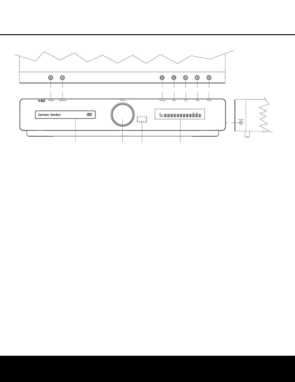
NOTE: To make it easier to follow the instructions that refer to this illustration, a larger copy may be downloaded from the Product Support section for this product
at www.harmankardon.com.
Power On/Off (Standby): When the HS 100
is connected to AC power, the ring around this button
will glow amber, indicating that the unit is in Standby
and is ready to be turned on. Press this button (or the
Power On Button 0 on the remote control) to turn
the unit on. When the unit is on, the amber illumination
around the button turns blue and the lighting surrounding the Volume Control A will turn blue.
1
Open/Close: Press this button to open or close
the Disc Tray.
2
Skip (Previous): Press this button to move
backward through the music tracks on a CD or the
chapters on a DVD.
3
Skip (Next): Press to move forward through the
music tracks on a CD or the chapters on a DVD.
4
Play/Pause: Press to initiate playback or to
momentarily pause playback. To resume playback,
press the button again. If a DVD is playing, action will
freeze and a still picture will be displayed when the
button is pressed.
5
Stop: Press this button once to place the disc in
the Resume mode, which means that playback will
stop; but as long as the tray is not opened, DVD playback will continue from the same point on the disc
when the Play button is pressed again. Resume will
also work if the unit was turned off. When this button
is pressed twice, playback of the disc will restart at
the beginning of the disc.
6
Source: Press this button repeatedly to scroll
through the available audio and video sources.
7
Headphone Jack: This jack may be used to listen
to the system’s output through a pair of headphones
with a standard 3.5mm stereo mini plug. Note that the
main room speakers will automatically be turned off
when the headphone jack is in use.
8
Information Display: This display delivers mes-
sages and status indications to help you operate the
HS 100 controller.
9 Remote Sensor: The infrared sensor that
receives commands from the remote control is behind
the front-panel lens in this area. To ensure proper
operation of the HS 100, it is important that this area
is not blocked or covered.
A
Volume Control: Turn this knob clockwise to
increase the volume, counterclockwise to decrease the
volume. If the HS 100 is muted, adjusting the volume
control will automatically release the unit from the
silenced condition.
B Disc Drawer: This drawer holds the discs played
in the HS 100. Be certain to properly seat all discs
carefully in the recess in the drawer tray. Do not
press down on the drawer when it is open, as this
will damage the player.
Power On/Off (Standby)
1
Open/Close
2
Skip (Previous)
3
Skip (Next)
4
Play/Pause
5
Stop
6
Source
7
Headphone Jack
8
Information Display
9
Remote Sensor
A
Volume Control
B
Disc Drawer
1
2
3
PLAYER
DVD-AUDIO
5.1ch
CD
JPEG MP3
RADIO
VCD
AUX
DVD
DIGITAL IN
WMA
PROG
RAND
HOUR
TRACK
CHAP
TITLE
GROUP
4
REP
PBC
5
6
A-B
P.SCAN
TEST
1 ALL
SEC
MIN
V.OFF
7
B
A
9
8
Page 6
FRONT-PANEL DISPLAY
6 FRONT-PANEL DISPLAY
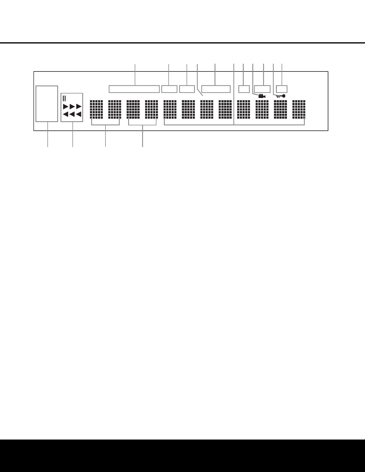
NOTE: To make it easier to follow the instructions that refer to this illustration, a larger copy may be downloaded from the Product Support section for this product
at www.harmankardon.com.
A Disc Type Indicators
B Program Indicator
C Random Indicator
D VCD Playback Control Indicator
E Repeat Indicators
F Time Indicators
G A-B Repeat Indicator
H Angle Indicator
I Progressive Scan Indicator
J Parental Lock Indicator
K Test Indicator
L Source Indicators
M Playback-Mode Indicators
N Title Indicators
O Chapter/Track Number Indicators
A
Disc Type Indicators: The CD, DVD or DVD-Audio
indicator will light to show the type of disc currently
being played.
B Program Indicator: This indicator lights when the
programming functions are in use.
C Random Indicator: This indicator lights when the
unit is in the Random Play mode.
D VCD Playback Control Indicator: This indicator
lights when the playback control function is turned on
with VCDs.
E Repeat Indicators: These indicators light when
any of the Repeat functions are in use.
NOTE: In addition to functioning individually to display
information about DVD, DVD-Audio or CD discs, the
NOF indicators also are used together as a group
to display information messages about the status of
the HS 100, such as the selected input’s name and
surround mode, the station playing when the tuner
is in use and specific function messages when a
DVD, DVD-Audio or CD disc is playing (such as
Reading when the disc is loading).
F Time Indicators: These positions in the indicator
will show the running time of a DVD in play. When a
CD is playing, these indicators will show the current
track time, time remaining in the current track, or the
total remaining time on the disc.
G A-B Repeat Indicator: This indicator lights when
a specific passage for repeat playback has been
selected.
H Angle Indicator: This indicator blinks when alter-
nate viewing angles are available on the DVD currently
playing.
I Progressive Scan Indicator: This indicator lights
when the unit sends out a progressive scan signal.
J Parental Lock Indicator: This indicator lights
when the parental lock system is engaged in order to
prevent anyone from changing the rating level without
a code.
K Test Indicator: This indicator lights when the TV
test screen is activated.
L Source Indicators: These indicators will light to
show which source is currently selected.
M Playback-Mode Indicators: These indicators light
to show the current playback mode:
N
Lights when a disc is playing in the normal mode.
NNN
When the HS 100 is in the Fast Search play
mode, two or three of these indicators will light to
show that the unit is in a Fast Play mode, depending
on the speed.
1
Lights when the disc is paused.
‹‹‹
Lights when the disc is in the Fast Search
Reverse mode. Two or three of these indicators will
light to show that the unit is in a Fast Play mode,
depending on the speed.
N Title Indicators: These two positions in the dis-
play will show the current title number when a DVD
disc is playing.
O Chapter/Track Number Indicators: When a
DVD disc is playing, these two positions in the display
will show the current chapter. When a CD is playing,
they will show the current track number.
K
TEST
SEC
PLAYER
JPEG MP3
RADIO
VCD
AUX
DVD
DIGITAL IN
GROUP
CD
TITLE
A
DVD-AUDIO
TRACK
5.1ch
CHAP
B
PROG
C
RAND
HOUR
D
REP
PBC
E
1 ALL
HJ
GF
A-B
I
P.SCAN
MIN
WMA
L
M
N
O
Page 7
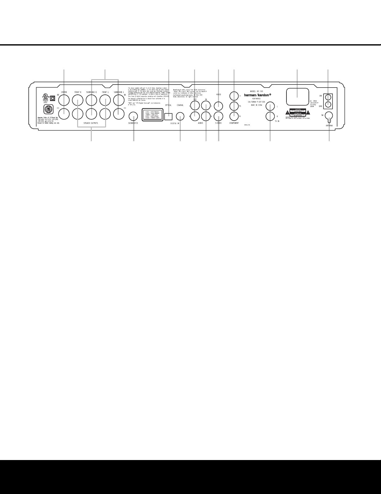
REAR-PANEL CONNECTIONS 7
REAR-PANEL CONNECTIONS
0
Center Speaker Outputs
1
Front Speaker Outputs
2
Surround Speaker Outputs
3
Subwoofer Output
4
Optical Digital Input
5
Coaxial Digital Input
6
Analog Audio Outputs
7
Analog Audio In
8
Composite Video Output
9
S-Video Output
A
Component Video Outputs
B
TV Audio In
C
AC Power Cord Jack
D
FM Antenna
E
AM Antenna
NOTE: To make it easier to follow the instructions that refer to this illustration, a larger copy may be downloaded from the Product Support section for this product
at www.harmankardon.com.
0
Center Speaker Outputs: Connect these outputs
to the matching + and – terminals on your center
channel speaker. The Green terminal is the positive (+)
terminal that should be connected to the Red (+) terminal on the speakers. Connect the Black (–) terminal
on the HS 100 to the Black negative (–) terminal on
your speaker. (See page 12 for more information on
speaker polarity.)
1
Front Speaker Outputs: Connect these outputs
to the matching + or – terminals on your left and right
speakers. The White terminal is the positive (+) terminal
that should be connected to the Red (+) terminal on
Front Left speaker, while the Red terminal is the positive
(+) terminal that should be connected to the Red (+)
terminal on Front Right speaker. Connect the Black (–)
terminals on the HS 100 to the Black (–) terminals on
the speakers. See page 11 for more information on
speaker polarity.
2
Surround Speaker Outputs: Connect these out-
puts to the matching + and – terminals on your surround channel speakers. The Blue terminal is the positive (+) terminal that should be connected to the Red
(+) terminal on the Surround Left speaker, while the
Gray terminal should be connected to the Red (+)
terminal on the Surround Right speaker. Connect the
Black (–) terminal on the HS 100 to the matching
Black negative (–) terminals for each surround speaker.
(See page 11 for more information on speaker
polarity.)
NOTE: You’ll find more details about all Audio/Video
connections under Setup and Connections on the
following pages.
3
Subwoofer Output: Connect to the SUB/LFE input
on the subwoofer.
4
Optical Digital Input: Connect the optical digital
output from an HDTV receiver, LD player, MD player,
satellite receiver or CD player to this jack. The signal
may be a Dolby Digital signal, DTS signal or a standard
PCM digital source.
5
Coaxial Digital Input: Connect the coax digital
output from an HDTV receiver, LD player, MD player,
satellite receiver or CD player to this jack. The signal
may be a Dolby Digital signal, DTS signal or a standard
PCM digital source. Do not connect the RF digital output of an LD player to these jacks.
6
Analog Audio Outputs: Connect these jacks to
the Record/Input jacks of an audio recorder for
recording.
7
Analog Audio In: Connect to the output of a
line-level analog audio source: TV, tape player,
Minidisc, PC, etc.
8
Composite Video Output: Connect this jack to the
video input on a television or video projector.
9
S-Video Output: Connect this jack to the S-video
input on a television or video projector.
A
Component Video Outputs: These outputs carry
the component video signals for connection to display
monitors with component video inputs. For standard
analog TVs or projectors with inputs marked Y/Pr/Pb or
Y/Cr/Cb, connect these outputs to the corresponding
inputs. If you have a high-definition television or projector that is compatible with high-scan-rate progressive
video, connect these jacks to the “HD Component”
inputs. Note that if you are using a progressive scan
display device, then “Progressive” must be selected in
the Video Setup menu in order to take advantage of the
progressive scan circuitry. See page 14 for more information on progressive scan video.
IMPORTANT: These jacks should NOT be connected to
standard composite video inputs.
B TV Audio In: Connect the analog left/right outputs
of a cable TV set-top, satellite receiver, or the analog
left/right stereo outputs from a video display with integrated digital tuner to these jacks.
C
AC Power Cord: Connect the AC power cord to
this jack when the installation is complete. To ensure
safe operation, use only the power cord supplied with
the unit. If a replacement is required, it must be of the
same type and capacity.
D
FM Antenna Jack: Connect to the supplied FM
antenna.
E AM Antenna: Connect the AM loop antenna sup-
plied with the receiver to these terminals with the white
wire connected to the “AM” terminal and the black wire
connected to the “GND” terminal. If an external AM
antenna is used, make connections to the AM and GND
terminals in accordance with the instructions supplied
with the antenna.
0
1
2
3
4
6
5
7
8
9
A
C
B
E
D
Page 8
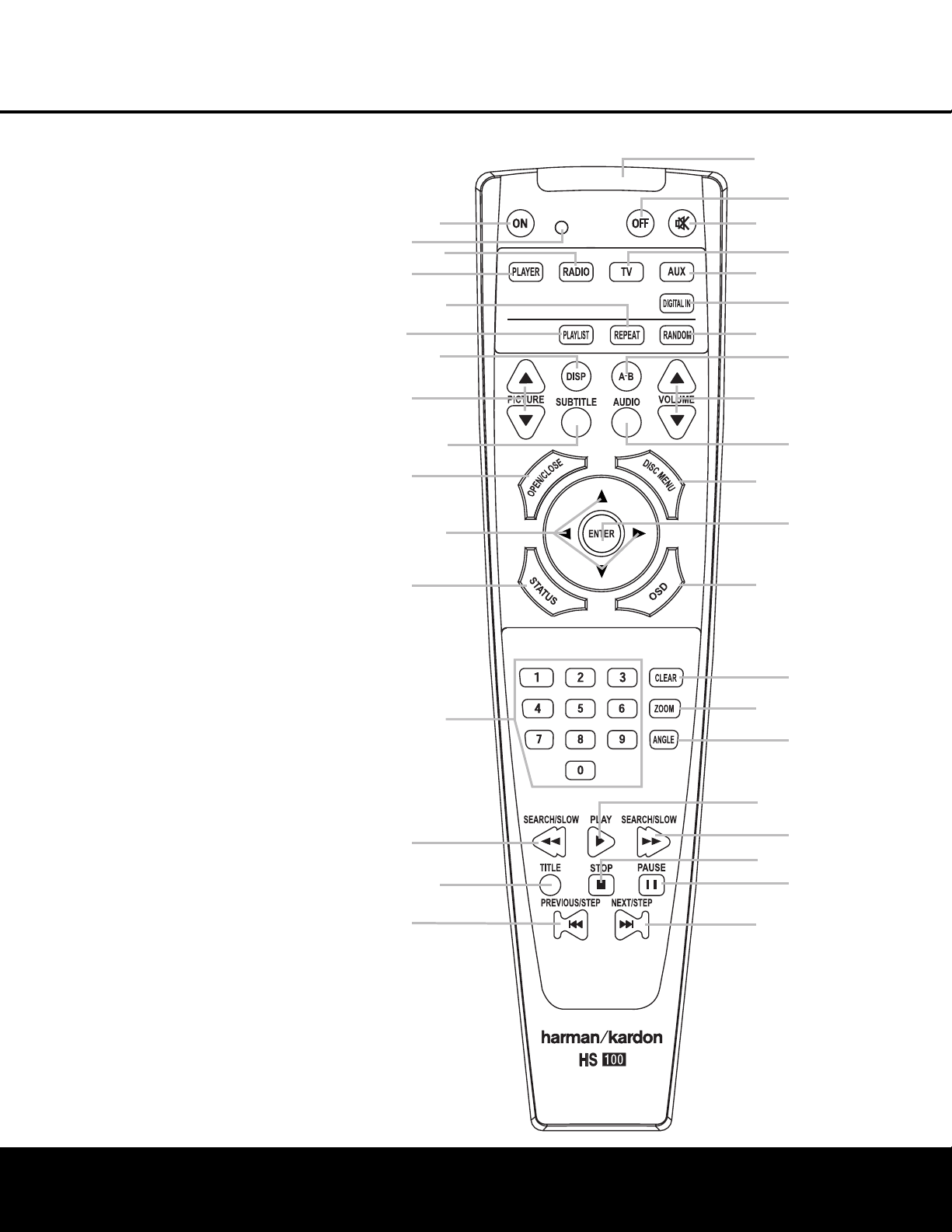
8 REMOTE CONTROL
REMOTE CONTROL
0
Power On
1
Transmit Indicator
2
Radio
3
Player
4
Repeat
5
Playlist
6
Display
7
Pic +/Pic –
8
Subtitle
9
Open/Close
A
Navigation Buttons
B
Status
C
Numeric Keys
D
Search/Slow Reverse
E
Title
F
Skip/Step (Previous)
G
Skip/Step (Next)
H
Pause
I
STOP
J
Search/Slow Forward
K
Play
L
Angle
M
Zoom
N
Clear
O
OSD
P
Enter
Q
Disc Menu
Audio
Volume Control
A-B Repeat
Random
Digital In
AUX
TV
Mute
Power Off
IR Transmitter Window
NOTE: To make it easier to follow the instructions
that refer to this illustration, a larger copy may be
downloaded from the Product Support section for
this product at www.harmankardon.com.
1
3
5
7
9
B
D
F
0
2
4
6
8
A
C
E
Q
P
O
N
M
L
K
J
I
H
G
Page 9

REMOTE CONTROL 9
REMOTE CONTROL
0
Power On: Press this button to turn the HS 100
on when it is in Standby mode.
1 Transmit Indicator: This LED will light red when
any button is pressed to confirm that the remote code
is being transmitted.
2
Radio: Press this button to select the internal
tuner as the input source. When the tuner is in use,
press this button to switch between the AM and FM
frequency bands.
3
Player: Press this button to select the internal
CD/DVD drive as the input source.
4
Repeat: Press this button to go to the Repeat
menu. You can repeat a chapter, track or the
entire disc.
5
Playlist: Press this button to change the playback
order of the disc.
6
Display: Press this button to change the bright-
ness of the front-panel display or to turn the display off
completely in the following order: FULL BRIGHTNESS
➜ HALF BRIGHTNESS ➜ OFF ➜ FULL BRIGHTNESS.
7
Pic +/Pic –: Press these buttons to move to the
previous or next image when viewing JPEG images.
8
Subtitle: When a DVD is playing, press this but-
ton to select a subtitle language or to turn subtitles off.
9
Open/Close: Press this button to open or close
the disc tray.
A
Navigation Buttons (M/N/K/L): Press
these buttons to move the cursor in the OSD.
B
Status: Press this button while a disc is play-
ing to view the banner display. Use the Navigation
Buttons
A
to move through the different features in
the banner display. When a symbol is highlighted, press
the Enter Button P on the remote to select it.
C
Numeric Keys: Press this button to select
numbers.
D
Search/Slow (Rev.): Allows you to search in
reverse through a disc while it is in Play mode. Each
time you press this button, the search speed changes
as indicated by a number of arrows on the right top of
your screen. After pressing the Pause Button H
and then pressing this button, each press will change
the slow-play speed as indicated by the number of
arrows on the right top of the screen.
E
Title: When a disc is playing, press this button to
go back to the first section of the disc.
F
Skip/Step (Previous): Press this button to go
to the beginning of the current track. Press it again
quickly to go to the beginning of the previous track.
After pressing the Pause Button H, each press
of this button will move the image in reverse, frame
by frame.
G
Skip/Step (Next): Press this button to go to the
beginning of the next track. After pressing the Pause
Button H, each press of this button will move the
image forward, frame by frame.
H
Pause: Press this button to freeze a picture (with
DVD/VCD) or pause playback (CD). Press it again for
normal playback.
I
Stop: Press this button to stop a disc. When a
disc is playing, if you press STOP and the Play Button
K
, the disc will resume play; i.e., it will start from the
same point on the disc where the unit was stopped.
If you press STOP twice and the Play Button
K
,
the disc will start from the beginning.
J
Search/Slow (Fwd.): Press this button to search
forward through a disc while it is in Play mode. Each
time you press this button, the search speed changes,
as indicated by a number of arrows on the right top of
your screen. After pressing the Pause Button H
and then pressing this button, each press of this button
will change the slow-play speed, as indicated by the
number of arrows on the right top of the screen.
K
Play: Press this button to begin playback of a
disc. If the disc drawer is open, pressing this button will
also close the drawer automatically.
L
Angle: Press this button to access various cam-
era angles on a DVD (if the DVD contains multiple
camera angles) or to rotate JPEG images.
M
Zoom: When a DVD or VCD is playing, press this
button to zoom the picture. There are four steps to the
zoom function, each progressively larger. Press through
each of the zoom stages to return to a normal picture.
N
Clear: Press this button to remove the Banner
menu from the screen.
O
OSD: Press this button to access the On-Screen
Display menu.
P
Enter: Press this button to activate a setting or
option.
Q
Disc Menu: Press this button to display the
actual DVD Disc menu on the TV screen in Play mode.
When playing discs with JPEG images, pressing this
button will access the thumbnails.
Audio: Press this button to access various audio
languages on a DVD (if the DVD contains multiple
audio streams).
Volume (+ or –): Increase/decrease the master
volume level.
A-B: Press this button to select section A-B and to
play repeatedly.
Random: Press this button for Random playback
in random order.
Digital In: Press this button to selects the audio
device connected to either digital audio input as the
input source.
AUX: Press this button to select the device con-
nected to the Audio In Jacks 7 as the input
source.
TV: Press this button to select the device con-
nected to the TV In Audio Jacks
B
as the input
source.
Mute: Press this button to mute the sound.
Press the button again, or press either of the Volume
Control Buttons
, to return to normal audio
output.
Power Off: Press this button to place the
HS 100 in the Standby mode.
IR Transmitter Window: Point this window
toward the HS 100 when pressing buttons on the
remote to make certain that the infrared commands
are properly received.
Page 10
10 INSTALLATION AND CONNECTIONS
INSTALLATION AND CONNECTIONS
Installation and Connections
After unpacking the HS 100 controller unit and the
speakers, the first step is to place each speaker and
the HS 100 controller unit in its location in your listening room. Consult the separate owner’s manual packed
with the speaker system for detailed information on
physical mounting of the speakers.
When making any connections between speakers and
the HS 100, as well as between the HS 100 and other
audio/video components, it is important that both the
HS 100 and external components be turned off,
preferably with the power removed from the AC outlet.
This protects against accidental turn-on that might
cause damage not covered by the products’ warranty.
When placing any speaker or the controller, make certain that it is on a solid surface capable of supporting
its weight, and make certain that there is a means for
connecting cables or speaker wires to reach through
the back of any cabinets or shelves to the components
they are connected to. As important, please note that
due to the weight of the speaker cabinets, particularly
the subwoofer, and the weight of and heat generated
by the HS 100 controller, there is the remote possibility
that the rubber padding on the bottom of the feet of
the system components may leave marks on certain
soft woods, wood veneers or carpets. Always use caution when placing any speaker or electronic component
on a material that is soft or porous, or of a significantly
different color than the feet or rubber padding on the
component.
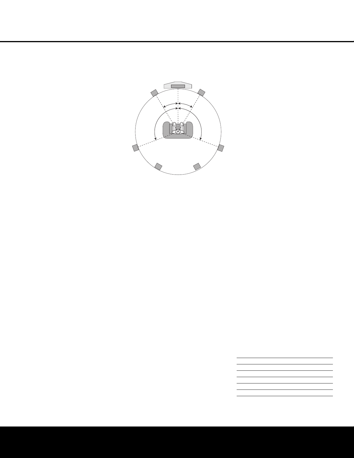
Speaker Placement
It is important that the speakers be placed in positions
that enable them to do the best job of reproducing the
sound as it was meant to be heard, regardless of the
program content. Particularly in a multichannel 5.1 system, the placement of speakers can have a noticeable
impact on the accuracy of the surround process.
When placing your speakers in a listening room, picture an imaginary circle starting at the center of your
video screen that arcs around the room with the prime
listening position, or “sweet spot” at the center of the
circle. Depending on the number of speakers in your
system, there is a recommended placement along the
arc for each speaker, though the specific construction
of your room (taking into account the available walls,
bookcases, or floor space at which the speakers may
be placed) will obviously have some impact on where
the speakers are ultimately located. As a general rule,
try to place all speakers so that they are positioned at
the same height as your ears when you are seated at
the prime listening position.
Use the following suggestions as a guide, and make
the changes needed to fit the speakers to your room.
Don’t be afraid to experiment a bit until you find the
right combination of locations that works for you. There
is no real “right” or “wrong” place to put the speakers;
work to optimize their locations so that audio moves
across the front of the room smoothly, without seeming
to jump from one speaker to another.
Center Channel Speaker
The ideal location for the center channel speaker is at
“0 degrees” in our circle, directly in front of the prime
listening position. Place the center channel speaker as
close to the top (or bottom) of the video screen as
possible so that when you position the front left/right
speakers the tweeters of all three front channel speakers are within 24" of one another.
Front Left/Right Speakers
The recommended placement for front left/right speakers is to place them at the 30-degree position with reference to the center channel speaker. The distance
between them should be about the same as the distance from the center channel speaker to the prime
listening position.
Although the natural tendency is to place the speakers
so they are parallel to the wall behind them, and thus in
line with the video screen, the preferred placement is
to angle the speakers slightly (“toe in”) so that they
point to the prime listening position.
Surround Speakers
In a 5.1 surround system, an additional pair of left/right
speakers is added to the front left, right and center
speakers. Although many believe that these speakers
should be placed at the rear of the room, the preferred
position for them is at the sides of the room, with rear
placement a second option when room conditions prevent the use of side-mounted surround speakers.
When side-wall mounting is possible, place the left/right
surround speakers at a point that is 110 degrees along
our circle from the center of the video screen. This
translates to placing them to the side and slightly
behind your preferred listening position. If possible,
angle the speakers in slightly so that they are pointing
toward the listener’s ears.
If it is not possible to place the surround speakers at
the sides of the room, the alternate position is at the
back of the room, about 150 degrees on our circle
from the center of the video screen. Another way to
spot the optimal, alternate rear-wall mounting position is
to place the left surround speaker on the back wall so
that it points directly at the front right speaker, and to
have the right surround speaker point directly at the
front left speaker. If possible aim the surround speakers
so that they point “in” toward the listening area, rather
than perpendicular to the walls.
NOTES ON SPEAKER PLACEMENT:
The limitations of your listening room, including the
placement of walls and furniture, may make it difficult
to follow the speaker placement suggestions shown
above. Depending on the specific layout of the room,
here are some ways to compensate for unusual
conditions:
• Try to follow the suggested placement, but move
the speakers within a few feet from the preferred
locations.
• Regardless of where they are placed, always try to
make certain that the main surround speakers are
the same distance from the front speakers. (For
example, try not to have the right surround speaker
further back into the room than the left surround
speaker.)
• If it is not possible to wall-mount or place speakers
on a shelf, consider the use of optional floor stands.
Main Speaker Connections
Once you have placed your left, center, right and surround speakers in the listening room, use the speaker
wire supplied with the HKTS 7 speaker system to connect the individual speakers to the rear panel of the
HS 100. Follow the instructions in the HKTS 7 owner’s
manual concerning connection of the speaker wire to
the back of each of the main speakers.
To simplify installation, the speaker wire included with
the HKTS 7 has a color marking tab at each end of the
wire to indicate the channel the wire’s speaker is connected to. When connecting the wire to the speakers,
we strongly recommend that you connect the wire in
con
formance with this color code, as it then makes it
easier
to match the color code for the speaker termi-
nals on the HS 100.
The color coding is as shown below:
Speaker Position Cable Color Code
Front Left White
Center Green
Front Right Red
Surround Right Gray
Surround Left Blue
If you wish to shorten the length of the speaker wires,
a set of colored stickers is included with the HKTS 7
owner’s manual. For consistency, apply the tab to the
Video Screen
Center Speaker
30° 30°
Front Right
Speaker
110 °
Side Surround
Right Speaker
Side Surround
Left Speaker
Front Left
Speaker
110 °
Alternate position for surround positions
Page 11

INSTALLATION AND CONNECTIONS 11
INSTALLATION AND CONNECTIONS
side of the cable pair that has a white stripe. The
speaker wires are not only color-coded for channel
identification; they are also color-coded for polarity.
Since proper polarity is important for system performance, note that the side of each cable pair with the
white stripe and color tab is the positive side, and the
pure black side of the cable pair is the negative. When
connecting the cables to the speakers, the red speaker
terminal is positive (+), and should be connected to the
side of the wire with the white stripe and color tab. The
pure black side of the cable, where there is no color
tab, is negative and should be connected to the black
speaker terminal.
Once the wires are connected at the speaker end, connect each speaker to the rear panel of the HS 100.
The color-coding on the speaker wire connectors
makes it easy to make the connections properly.
The positive (+) connection for the Front Speaker
Connections 1 are white for left and red for
white, positive connection for the Center Speaker
Connection 0 is green, and the positive connections
for the Surround Speakers 2 are blue for left and
gray for left. In each case, the corresponding black side
of each speaker cable is the negative (–) connection
and goes to the matching black terminal for the
speaker.
Subwoofer Placement and Connection
Since subwoofers produce nondirectional sound, they
may be placed almost anywhere in a room. Actual
placement should be based on room size and shape
and the type of subwoofer used. One method of finding the optimal location for a subwoofer is to begin by
placing it in the front of the room, about six inches
from a wall, or near the front corner of the room.
Another method is to temporarily place the subwoofer
at your normal listening position, and then walk around
the room until you find a spot where the subwoofer
sounds best. Place the subwoofer in that spot, or you
may wish to experiment with the best location for a
subwoofer in your listening room.
Using the audio interconnect packaged with the
HKTS 7 system, connect one end to the Subwoofer
Output 3 on the rear panel of the HS 100 and
connect the other end to the “SUB” input on the
subwoofer.
Audio Equipment Connections
Since the HS 100 is a complete integrated home theater system with an onboard DVD Audio/Video player
and tuner, you may not need to make any additional
audio equipment connections. However, if you have any
external audio components, they should be connected
as follows:
Products with digital audio outputs, such as an external
CD changer, set-top cable box, satellite receiver, video
game console, compatible computer sound card or
HDTV receiver may be connected to either the
Optical 4 or Coaxial 5 Digital inputs.
Connections to the analog audio output of a cable settop, satellite receiver, or the Left/Right analog output of
a TV set with built-in digital television tuner should be
connected to the TV Audio Inputs B.
You may connect the outputs of any other analog audio
device, such as a phono preamp, video game console,
camcorder, audio recorder or similar to the Analog
Audio Inputs 7. If you are connecting an audio
recorder to the HS 100, the record/in jacks on the
recording device should be connected to the Analog
Audio Outputs 6 on the HS 100.
Video Equipment Connections
Depending on the type of TV set or video display to be
used, connect the HS 100 to the display using one of
the following methods:
• If you have a high-definition, or “digital”, television,
connect the Component Video Outputs B to a
matching set of component inputs on the display.
• If your TV set has only S-video and standard,
composite video inputs, we recommend that the
S-Video Output 9 be used as the connection.
• When a standard, composite video input is all that is
available on the TV set for video input, connect the
Composite Video Output 8 to the TV.
System Connections
Connect the FM antenna supplied with the HS 100,
or an optional, external FM antenna feed to the FM
Antenna Jack D. If the antenna uses 300-ohm
twin-lead cable, you must use an optional 300-ohm to
75-ohm adaptor to make the connection. Assemble
the supplied AM loop antenna so that the tabs at the
bottom of the antenna loop snap into the holes in the
base. Connect the white wire to the “AM” terminal and
the black wire to the GND Terminals E.
Connect the AC power cord to the AC Power Cord
Jack C, and then plug the cord into an unswitched
AC outlet. Note that the ring surrounding the Power
On/Off switch will turn amber to indicate that the
HS 100 is connected to an AC power source and
in the Standby mode.
System Preparation
Remove the protective plastic film from the HS 100’s
front-panel lens. If left in place, this film may affect the
performance of the remote control.
Install the three supplied AAA batteries in the remote,
as shown below.
To remove the battery cover, place your thumb on the
round inset area on the door and gently press upward
until the door slides out. When inserting the batteries
be certain to follow the (+) and (–) polarity indications
that appear at the bottom of the battery compartment.
Replace the battery compartment cover by pressing it
down toward the bottom of the remote until it snaps
into place.
Connecting the AC Power
You are now ready to power up the HS 100 controller
before beginning the final adjustments.
1. Plug the AC power cord into the AC Power Cord
Jack
C
, and then into an unswitched AC outlet.
Note that the Power Indicator
1
will turn orange,
indicating that the unit is in the Standby mode.
2. Turn the HS 100 on either by pressing the Power
On/Off
1
or the Input Source Selector4on
the front panel, or via the remote by pressing the
Power On Button
0
on the remote. The Power
Indicator
1
will turn blue to confirm that the unit is
on, and the Main Information Display
will also
light up.
Congratulations! You have now completed the physical
installation and connection of your HS 100 system and
only a few configuration steps are needed to tailor the
way the HS 100 operates to meet your needs and the
requirements of your listening room. Please continue
with the steps on the following pages to make certain
that your new system delivers all the performance it
was designed to provide.
Page 12

12 SYSTEM SETUP
SYSTEM SETUP
System Setup
The final step in the installation of the HS 100 is to
establish the system’s configuration. Before proceeding,
make certain that the HS 100 is properly connected to
a video display and an AC power source. Turn on the
video display, and switch its input, if necessary, to the
input connected to the HS 100’s video output.
Turn on the HS 100 by pressing the Power On/Off
Switch on the front panel or the Power On
Button 0 on the remote. Note that the lighting
surrounding the Power On/Off Switch will turn
blue, a blue light will surround the front-panel Volume
Control 9, the Information Display 8 will light
and the HS 100 screen will appear on your video
display.
In many cases you will not need to change the default
settings. This is normal, as we have anticipated the typical system setup. Of course, you may return to the
setup menus and change them at any time to reflect a
change in your personal preferences or equipment
selection.
System Defaults
General Functionality of the OSD Menu
The setup and control of the HS 100 takes place in an
advanced user-guided On Screen Display (OSD) menu
system. The OSD can be activated by pressing the OSD
Button
O
on the remote control. Pressing this button
again de-activates the OSD.
The main menu consists of a PLAYER menu,
RADIO menu, TV menu, AUX menu,
DIGITAL IN menu and a SET-UP menu.
The PLAYER menu will show all information and
options available for the disc currently playing. The
RADIO menu will show radio and RDS options.The
TV, AUX and DIGITAL IN menus show the
surround options for these specific audio inputs.The
SET-UP menu will help you configure all audio and
video settings which are normally made only once.
Each main menu contains submenus.These submenus
are shown as icons on the left side of the menu. They
may be selected by moving the white highlighted square
around the icon by pressing the Navigation Buttons
A
. Menus may be activated by pressing the Enter
Button
P
when an icon is highlighted. When the
Enter Button
P
has been pressed, the color of the
icon will change to dark blue and the current settings of
this submenu will appear on the right side of the menu.
Although each menu has various submenus and
settings, they are all navigated in the same way. All submenus, settings and options can be accessed with the
help of the Navigation Button
A
and the Enter
Button
P
on the remote control.
å Main Menu Line
∫ Submenus
ç Current Settings
∂ Command Descriptions
é Option Descriptions
To change a setting, simply move the highlight cursor to
the setting you wish to change.This setting will be highlighted in light blue, and a brief explanation will appear
in the Upper Menu Line on the bottom of your screen,
together with the available options for this setting on the
Lower Menu Line. Use the
M/N
Navigation Buttons
A
to highlight the requested option for this setting.
Press the Enter Button
P
to activate the new
setting.
Setup Menu
The first step in checking or changing the system
defaults is to access the SET-UP Menu. First,
make certain that the HS 100 Controller is properly
connected to a video display, and that power is
connected. For this process, however, you do not
need to load a disc into the unit.
During Stop, Pause or Play mode, if you press the OSD
Button
O
on the remote, the main menu appears on
the screen.
In the SET-UP menu you will find submenus for
making or changing all settings and adjustments for
both the Audio and Video aspects of your HS 100.
To access the SET-UP Menu, press the OSD Button
O
, and press theM/N/K/LNavigation
Buttons
A
until SET-UP is highlighted. Press
Enter Button
P
to activate the SYSTEM
settings:
System Settings
The System Setting submenu contains the following
sections. Follow the explanations in the Upper Menu
Line at the bottom of the screen to change settings.
Display Language: This setting selects the language
that will be used for the HS 100’s OSD menus and
other system messages. The default is English, but you
may also select French, Spanish, German or Italian.
Preferred Subtitle Language: This setting selects the
language used for the display of subtitles. The default
setting is OFF, which plays discs without subtitles. To
set the player so that subtitles will always play in a specific language when they are available, select from any
of the choices shown on the Option Descriptions É
when adjusting this item, as shown above. If you do not
find your preferred language in the list of options, you
may select a preferred language by first pressing the
‹/›
Navigation Buttons k during the setting
adjustment so that OTHER is highlighted. Press the
Enter Button z and then use the Numeric Keys
m to enter the four-digit code listed on page 31 for
the desired language. This selects a preferred subtitle
language, but it will only be available when the disc
being played contains that language. The list of subtitles available on any given disc is always shown on the
disc jacket, usually at the bottom of the back cover.
Note that the subtitles may also be switched on or off,
or a new language selected during playback using the
Subtitle Button 8, as described on page 21.
Panel Time-Out: This settings selects the time-out
interval for the front-panel Information Display 9.
The default setting is OFF, which disables this feature
so that the front-panel indicators are always illuminated.
You may also choose five to 20 seconds as the length
of time after you press any button on the front panel or
remote for the display to go out. To view the displays
when they are off, press any button on the remote.
Status Bar Time-Out: This setting selects the time-out
interval for the on-screen Status Bar that appears at the
top of your video screen when the Status Button l
is pressed while a disc is playing. During DVD playback,
the status bar shows the current title and chapter, as
well as the elapsed or remaining time in the current
title. You may program the status bar to remain on
screen for either five or 20 seconds after the Status
Button l is pressed. When OFF is selected, the
time-out is disabled, and the status bar will remain on
the screen until the Status Button l or Clear
Button x is pressed.
Parental Control: This setting enables you to restrict
viewing to films or other discs encoded with parental
control information to a specific level or below, and it
also allows you to change the password that must be
entered to change the settings for this option. The
default setting allows all discs to be played, but you
may change the setting so that viewing is controlled
within eight steps, with lower numbers being more
å
∫
é
∂
Page 13

SYSTEM SETUP 13
SYSTEM SETUP
restrictive and high numbers allowing more material
to be viewed. The steps correspond to the standard
MPAA ratings symbols as follows. Additional information about movie ratings is available online at
www.mpaa.org/movieratings.
• Step 1 is equivalent to a “G” rating for general audiences with material appropriate for all viewers.
• Step 2 is an intermediate level between “G” and
“PG” rated material.
• Step 3 is equivalent to a “PG” rating.
• Step 4 is equivalent to a “PG-13” rating.
• Step 5 is an intermediate level between “PG-13” and
“R” rated material.
• Step 6 is equivalent to an “R” rating.
• Step 7 is equivalent to an “NC17” rating.
• Step 8 allows all discs to be played, regardless
of their content rating.
To access the Parental Control settings, press the
K/L
Navigation Buttons k until the current
setting on the Parental Control Settings line is highlighted and press the Enter Button z. Next, enter
the default password by pressing “8888” using the
Numeric Buttons m. Finally, use the
M/N
Navigation Buttons k to highlight the desired
parental control level as shown on the Options
Descriptioins É line as described above. You may
also change the password by highlighting NEW
PASSWORD, pressing Enter Button z and
by following the instructions that appear in the
Command Descriptions ∂ line.
Disc Recognition: This setting controls the Disc
Recognition feature. When turned on, it allows you to
pause a DVD-Video disc, remove it from the player,
play another disc, and then resume the playback of the
original disc at a later time from the point at which you
paused. When a previously played disc is reinserted
in the HS 100, an on-screen status message will ask
whether you wish to start playback from the beginning
of the disc or resume at the point where you left off.
Note that even when the setting is activated, you must
pause
the playback, rather than bring it to a full stop,
and the unit must not be turned off between discs.
PBC Support: This setting controls the activation of
PBC (Play Back Control) Support for VCD discs. If you
plan to play VCD discs, which are a CD-ROM-based
format that predates DVD, we recommend that the setting be turned ON.
Screen Saver: This setting controls the activation of
a screen saver that prevents the image of the “splash
screen” from being “burned” into the face of your video
display when a disc is stopped for more than five minutes. If you use the HS 100 with a plasma display,
direct-view CRT set or a CRT-based projector, we
strongly recommend that the setting be turned ON.
Show Angle Icon: This setting controls the activation
of the Angle Icon. When this setting is turned ON,
the Angle Icon, which is a small image of a movie
camera, will appear in the upper right corner of the
screen when multiple-angle material is available on the
disc being played. When the icon appears, press the
Angle Button v on the remote to switch between
the available views or program material.
Audio Setup Menu
This menu establishes the HS 100’s configuration for
general audio settings, such as preferred language and
digital audio settings.
As with all setup menus, press the OSD Button `
to activate the main menu screen, and then press the
M/N
Navigation Buttons k so that SETUP is
highlighted. Press Enter Button z, and then use
the
M/N/K/L
Navigation Buttons k until the
AUDIO SETUP menu is highlighted within a
white outline and press the Enter Button z again.
Finally, press the
M/N/K/L
Navigation Buttons
e once more to move the highlight to the Control
Settings ç side of the menu screen.
The following adjustments are available on the
AUDIO SETUP menu:
Preferred Audio Language: This setting is used to
select the default language that will be used for program playback. The factory default setting is English,
but you may choose French, Spanish, German or
Italian by making a selection on the Options
Descriptions É line. To select a language other than
those shown, select OTHER from the choices on
the Options Descriptions É line and press the
Enter Button z. Then, use the Numeric Keys p
to enter the four-digit code listed on page 31 for the
desired language. This selects a preferred audio program language, but it will only be available when the
disc being played contains that language. The list of
languages available on any given disc is always shown
on the disc jacket, usually at the bottom of the back
cover. Note that the audio playback language may
also be changed at any time during playback using
the Audio Button , as described on page 20,
but any changes made will only be effective during
playback of that disc.
Dynamic Range: This setting allows you to take
advantage of the programming present on some
Dolby Digital recordings to reduce the volume of
louder, peak passages while maintaining intelligibility
of quieter passages. This means that you may listen
to programs at a level that allows the full impact of a
soundtrack to be heard at a volume that is lower than
you might otherwise use to avoid complaints about
loud volume levels. The HS 100 accomplishes this by
compressing the audio to a greater or lesser degree,
depending on which setting you choose. Three options
are available:
• MINIMUM does not make any changes to the
original playback, and should be used when the
volume setting in the listening room may be as loud
as you desire.
• MEDIUM applies a moderate amount of com-
pression so that louder passages are a little quieter.
• MAXIMUM applies more compression so that
louder passages are much softer.
Feel free to experiment with the settings at any time.
Note that if your receiver or processor also allows you
to program the dynamic range setting, also known as
the “Night Mode,” you do not need to make any adjustments on the HS 100 and should leave the setting at
MINIMUM.
Delay Unit: This setting selects the measurement system used in entering delay times when the AUDIO
ADJUSTMENTS menu is activated. Distance
entry in feet is the default, but you may alternatively
choose to enter the distances in meters.
Tone Control: This setting determines whether the
Tone Controls are activated. When OFF is selected,
the audio output is run “flat” with no tone cut or boost.
When ON is selected, the tone control settings made
in the next two adjustments are applied.
Bass Level: When the Tone Control setting (above) is
ON, the amount of bass (low frequency) boost or cut
selected here is applied to the output signal. To change
the setting, make certain that the number at the right
side of the Bass Level Command Descriptions Line is
press the Enter Button P and then use the
Navigation Buttons A to change the setting.
Treble Level: When the Tone Control setting (above)
is ON, the amount of treble (high frequency) boost
or cut selected here is applied to the output signal. To
change the setting, make certain that the number at the
right side of the Treble Level Command Descriptions
Line is press the Enter Button P and then use the
M/N
Navigation Buttons A to change the setting.
DVD Sound Mode: This setting selects the surround
mode that will be used when a DVD is playing. (To set
the surround mode option for another input, such as “TV,”
“Digital In,” “AUX” or the unit’s internal AM/FM tuner, go
to the specific menu for that input.) The factory default
is ORIGINAL, which will play back DVDs in the
format output from the disc, such as Dolby Digital or
Page 14

SYSTEM SETUP
14 SYSTEM SETUP
DTS. To select the mode that will be used when a disc
with two-channel audio is playing, make certain that
the mode name at the right side of the DVD Sound
Mode Command Descriptions Line is highlighted and
then press the Enter Button P. Use the
M/N
Navigation Buttons A to change the setting.
Audio Adjustment
The Audio Adjustment Submenu contains the speaker
delay and output level adjustment settings of the
HS 100. Follow the explanations in the Command
Options ∂ on the bottom of your screen to make
adjustments.
Delay
Due to the different distances between the listening
position for the front and surround channel speakers,
the amount of time it takes for sound to reach your
ears from each set of speakers is different. You may
compensate for this difference through the use of the
delay settings to adjust the timing for specific speaker
placement in your particular home theater or listening
room. Before proceeding, measure the distance
between each speaker and the preferred listening
location.
Next, press the
M/N/K/L
Navigation Buttons
A so that the second of the two AUDIO icons in
the Sub-Menus column ∫ is surrounded by a white
outline, with the icon box turning dark, rather than light,
blue. This is the Audio Settings Menu. Next, press the
M/N/K/L
Navigation Buttons A until the dis-
tance setting under the Front Left speaker title is highlighted and press the Enter Button P. To change
the setting, press the
M/N
Navigation Buttons A
so that the number highlighted in the Options
Description line é at the bottom of the screen is
the distance from the speaker to the listening position.
Press the Enter Button P when you are done.
Press the
M/N/K/L
Navigation Buttons A to
move across the menu screen to each of the distance
settings under each of the rest of the speaker positions, and repeat the procedure to enter the distance
setting. Note that distance setting for the subwoofer
does not need to be entered, as delay is not a factor
with low-frequency information.
Output Level Adjustment
Output level adjustment is a key part of the configuration process for any surround sound system.
NOTE:
Listeners are often confused about the operation
of the surround channels.While some assume that
sound should always be coming from each speaker,
most of the time there will be little or no sound in the
surround channels.This is because they are only used
when a movie director or sound mixer specifically
places sound there to create ambience, a special
effect or to continue action from the front of the room
to the rear. When the output levels are properly set,
it is normal for surround speakers to operate only
occasionally.Artificially increasing the volume to the
rear speakers may destroy the illusion of an enveloping
sound field, which duplicates the way you hear sound in
a movie theater or concert hall.
For ideal surround playback, the output level from each
channel should be equal, and in most cases the factory
default setting of 0dB should accomplish that. However,
in some cases the specifics of your listening room may
require some adjustments. To adjust the output levels,
first put in a disc with test tones or content you are
familiar with, and that has a reasonably even level without a great deal of changes. Then, press the
M/N
/
K/L
Navigation Buttons A until the output level
setting with the factory default of “+0dB” at the bottom
of the list under the Front Left speaker distance setting
is highlighted. If an increase or decrease needs to be
made to the level, press the Enter Button P and
then use the
M/N
Navigation Buttons A so
that the desired level is highlighted in the Options
Description line é at the bottom of the menu
screen. Press the Enter Button P, and then press
the
M/N/K/L
Navigation Buttons A to move
across the menu screen to each of the output level
settings under each of the rest of the speaker positions,
and repeat the procedure to enter the output level offset, if needed, that brings all of the channels to the
same output volume. You may need to repeat this procedure more than once to accurately set the levels.
Video Setting
This menu establishes the DVD’s configuration for video
format settings such as aspect ratio and output scan.
As with all setup menus, press the OSD Button y
to activate the main menu screen, and then press the
M/N
Navigation Buttons k so that SETUP
is highlighted. Press the Enter Button z, and then
use the
M/N/K/L
Navigation Buttons k until
the VIDEO SETUP menu is highlighted within
a white outline, and press the Enter Button z
again. Finally, press the
M/N
Navigation Buttons
e once more to move the highlight to the Control
Settings ç side of the menu screen.
The following adjustments are available on the Video
Setup menu:
Aspect Ratio: This setting selects the aspect ratio
of video programming. Your choice should be made
according to the shape of your video display and your
personal preferences. Three choices are available:
• 16:9: If you have a widescreen (16:9) display, or a
display that has a widescreen mode, choose this setting. With this setting, the HS 100 will adjust the output for widescreen movies so that they fill the entire
screen in the proper aspect ratio. Note, however, that
in this setting a disc recorded in the 4:3 aspect ratio
will appear in the widescreen as a boxed image in
the center, with black columns on the left and right
side of the screen. Note that if the widescreen option
is chosen and a widescreen movie is played on a
conventional 4:3 aspect ratio set, the image will be
distorted due to vertical compression.
• 4:3 Letterbox: If you have a standard, 4:3 aspect
ratio video display, choose this setting if you wish to
see the entire frame of the movie as it is recorded
on the disc without any image cutoff at the left and
right sides. While this allows widescreen movies to
be shown in their entirety, they will occupy a smaller
portion of the screen and black “letterbox” bars may
appear at the top and bottom of the screen.
• 4:3 PanScan: If you have a standard, 4:3 aspect
ratio video display and prefer to have widescreen
movies displayed without the black bars at the top
and bottom of the screen, choose this option. Note,
however, that since most DVDs do not contain special “pan/scan” coding that allows the on-screen
image to follow the action, you may find that while
the image will fill the screen, the vertical spread will
cause it to be cropped at the left and right side.
Scan Type: This setting allows you to select
between progressive and interlaced scanning for the
Component Video Outputs ⁄ to maximize the
image resolution for the type of video display in use.
When all desired setup and configuration entries have
been made, press the OSD Button y to return
the player to normal operation and you are ready to
enjoy the finest in DVD or CD playback. Note that the
output at the S-Video ‚ and Composite Video ª
outputs will always be standard-rate video that is
compatible with any television set or video display.
Two choices are available:
Page 15

SYSTEM SETUP
SYSTEM SETUP 15
• Progressive: Select this option if you have a video
display that is compatible with input sources of 480p
or greater. Displays labeled as “HDTV Ready,” including virtually all large-screen LCD and plasma displays, are compatible with progressive scan.
• Interlaced: Select this option when you are using
an older video display that has Y/Pr/Pb component
inputs, but which is not capable of displaying high
scan rate, or “HD,” signals.
Video Mode: This setting affects only the Component Video Outputs ⁄, and it controls how the
video signals are optimized for progressive scan display. In most cases, the “automatic” mode is your best
choice, as it senses whether the disc being played was
originally recorded on video or shot on film. However,
in some cases you may wish to compensate for errors
in the disc authoring that occur when the frame rate is
not properly maintained when films are converted to
video. Three choices are available:
• Auto: This is the recommended setting, as it lets the
HS 100 analyze the signals from the DVD and adjust
the output accordingly.
• Movie: Choose this option for optimal playback of
material that was shot on film, even though you are
viewing it on video via a DVD.
• Video: Choose this option for optimal playback of
material that was shot directly to video, such as concerts and sports programming.
Video Adjustments Menu
This menu allows you to adjust five key parameters
of the video signal to compensate for differences
between HS 100 and other video sources. You may
use either the HS 100’s built-in color bar test signal
or a test disc as the standard for the adjustments. To
ensure that your system is properly optimized, we
strongly recommend that you adjust your video display
using the display’s own controls before making any
changes to the HS 100’s output. Once the display is
properly calibrated with all settings on the HS 100 set
to their midpoint, use the controls on this menu to finetune the HS 100’s output.
Due to the nature of these settings, the navigation is
somewhat different from the HS 100’s other menus
and controls. The menu itself is called up in the same
way as the other menus. Press the OSD Button y
to activate the main menu screen, and then press the
K/L
Navigation Buttons k so that SETUP
is highlighted. Press the Enter Button z, and then
use the
M/N/K/L
Navigation Buttons k until
the VIDEO ADJUSTMENTS menu box
(which contains an icon with slider controls and the
word VIDEO, and is located at the bottom of the
column in the Submenus Area ∫) is highlighted
within a white outline. Then press Enter z again.
When you press Enter z the video adjustments will
appear inside a black bar at the top of the screen, with
either the video from a disc being played or the splash
screen shown on the rest of the screen.
To change any of the video adjustments shown at
the top of the screen, first press the
M/N/K/L
Navigation Buttons k so that the “+” to the right
of a parameter name is highlighted to increase the setting or “–” to the right of a parameter name is highlighted to decrease the setting. Then press the Enter
Button z to change the value as shown by the
number of blue lines to the left or right of the center
line. When only the dark center line is shown with no
blue lines, the setting is at the midpoint default value.
When adjusting the Black Level setting, note that the
adjustment available is to either have the setting at the
midpoint, which provides a full “0 to 100” black level
setting, or “full,” which complies with standards for
video with what is called “setup,” or a “7.5 to 100”
black level setting.
Changes to any of the settings may be made with
a test disc playing, or you may use the internal test signal by pressing the
M/N/K/L
Navigation Buttons
k until the word OFF is highlighted next to the
TEST SCREEN line. To activate the test signal,
press the Enter Button z and note that a special
combination test signal, including both color bars and
gray scale along with 100% black and white fields, will
be displayed. To recall the video controls, press the
OSD Button y and then navigate among the settings and make any necessary changes following the
steps in the previous paragraph.
Test Screen
With the test screen showing on your video display, the
following adjustments may be made:
• The proper color intensity setting on your TV.
• Proper color adjustments using the color bars, which
should be (left to right) black, white, yellow, cyan
(turquoise), green, magenta, red, blue, black.
• The proper color transition, seen as sharp
separation of the bars.
• The performance of the color circuits in your TV
(with “Video” signals); bar edges should show
no vertical crawling dots.
With the gray scale and the black/white fields below
the color bars, the brightness and contrast of your
screen can be adjusted.
TV Picture Adjustment With Test Screen
Brightness Adjustment:
1. Turn down the color control on your TV until the
color bars are visible in black and white.
2. Adjust the contrast to the lowest level where you still
can see all bars within the gray scale in the test picture separately and clearly.
3. Adjust the brightness so that the bars in the gray
scale are all visible. The bar furthest to the left has to
be as black as possible rather than gray but the next
gradation must clearly be distinct from it. All the bars
in the gray scale should be gradually and evenly
changing from black to white, left to right.
Contrast Adjustment:
1. Adjust the contrast on your TV until you see a bright
white bar in the lower right corner of the screen and
a deep-dark-black bar to the left. The optimal contrast setting will depend on your preference and the
surrounding light in the TV room.
2. If the brightness of the white bar no longer increases
when the contrast is turned up or the borders of the
white “harman/kardon” letters on top bloom (overlight) into the black areas (drastically decreasing
the sharpness of the type), the contrast has been
turned up too much. Reduce the contrast until these
effects disappear and the video still looks realistic.
3. If you are watching TV with customary surrounding
daylight, adjust the contrast so that a normal video
picture has about the same look as the surroundings
in your room. That way the eye is relaxed when
watching the TV picture. This contrast setting may be
reduced when the surrounding light is dimmed,
thereby usually improving the sharpness of a video
significantly.
4. The gray scale in the middle line needs to have
the same clear difference between each bar as
Page 16

SYSTEM SETUP
16 SYSTEM SETUP
before the contrast adjustment. If not, go back to
“
Brightness Adjustment” and repeat Step 3 and then
“
Contrast Adjustment,” making only minor adjust-
ments each time for optimization.
Color and Tint Adjustment
1. When the brightness and contrast are set optimally,
adjust the color control to the level of your preference. Set the level where the colors look strong but
still natural, not overdone. If the color level is too
high, depending on the TV, some of the bars will
seem wider or the color intensity will not increase
while the control is turned up. Then the color control
must be reduced again. Ultimately, you also should
test the color intensity with a video – e.g., pictures
of natural faces, flowers, fruit and vegetables, and
other common natural articles for an optimal setting
of the color intensity.
2. Use the large white bar below the gray scale to
tweak the warmth of the picture. Every viewer has a
preference as to how the glow of the picture should
be. Some prefer a little colder picture, some a
warmer glow. The Tint function and the white bar
can be used to control this. Adjust the Tint to the
level where you feel the white color has the tone
you prefer.
Page 17

TERMINOLOGY AND DVD BASICS 17
TERMINOLOGY AND DVD BASICS
Terminology
Since DVD players such as the one built into the
HS 100 share some of the characteristics and technology of CD players, many of the terms and operational
concepts used to describe DVD playback are similar
to what you may be familiar with from CD players and
changers. However, if this is your first DVD product,
some of the terms used to describe the features of a
DVD player may be unfamiliar. The following explanations should solve some of the mysteries of DVD, and
help you to enjoy all the power and flexibility of the
DVD format and the DVD.
Aspect Ratio: This is a description of the width of a
video image in relation to its height. A conventional
video screen is four units wide for every three units of
height, that’s why the ratio is called “4:3”. Newer wide
aspect ratio video displays are 16 units wide for every
nine units of height, making them more like the screen
in a movie theater. The program material on a DVD may
be recorded in either format and, in addition, you may
configure the DVD to play back in either format,
depending on the features recorded on a disc.
Title: For a DVD, a title is defined as an entire movie or
program. There can be as many chapters within a title as
the producers decide to include. Most discs include only
one title, but some may have more than one, to give you
a “Double Feature” presentation.
Chapter: DVD programs are divided into chapters and
titles. Chapters are the subsections programmed into a
single title on a disc. Chapters may be compared to the
individual tracks on an audio CD.
Progressive scan: DVD offers progressive scan video
outputs for use with compatible high-resolution televisions and projectors. Before DVD, no consumer medium
could store, transmit or display video with full resolution.
To conserve bandwidth, analog compression (interlacing)
is employed: first the odd-numbered lines of a frame are
displayed, followed by the even-numbered lines. The
result is that only half of the video image is drawn at one
time; the viewer's brain must reassemble the complete
image. This is acceptable, if the monitor is not too large
and if there is not too much motion in the image. Large
displays and fast-moving images reveal the limitations
of this system. Thanks to DVD’s immense data capacity,
images may now be stored intact (progressively), so that
all the lines in each frame (odd and even) are shown at
the same time. But because older analog video displays
cannot handle a progressive signal, all current DVD
players generate an interlaced output for compatibility.
The HS 100 features true progressive scan video output
for use with compatible TVs and projectors and with all
“digital-ready” and high-definition display devices via the
component video output. The result is 40% greater light
output than a conventional TV and a stunningly detailed
high definition image, along with an almost complete
absence of visible scanlines and motion artifacts. Of
course, traditional Y/Pr/Pb component video, S-video
and composite video outputs are also available for use
with conventional televisions and projectors.
Multiple Angle: DVDs have the capability to show up
to four different views of the same scene in a program.
When a disc is encoded with multiple-angle information, pressing the Angle button will enable you to switch
between these different views. Note that at present, few
discs take advantage of this capability and, when they
do, the multiple-angle technology may only be present
for short periods of time within the disc. Producers will
usually insert some sort of icon or graphic in the picture
to alert you to the availability of multiple viewing angles.
Reading: This is a message that you will see after
you’ve loaded the disc and the tray has closed. It refers
to the fact that the player must first examine the contents of the disc to see whether it is a CD or DVD, and
then extract the information about the type of material
on the disc, such as languages, aspect ratios, subtitles,
number of titles and more. The slight delay while the
contents of the disc are read is normal.
Resume: The operation of the Stop Button on the DVD
works differently from what you are used to on CD
players. On a traditional CD player, when you press the
Stop button, the unit does just that – it stops playback.
On a CD player, when you press the Start button again,
the disc starts from the beginning. With the DVD, however, you have two options when playing DVD discs.
Pressing Stop once will stop playback, but it actually
puts the unit in the Resume mode. This means that you
can turn the machine off and, when you press Play the
next time, the disc will resume or continue from the
point on the disc where the Stop button was pressed.
This is helpful if you are watching a movie and must
interrupt your viewing session but wish to pick up
where you left off. Pressing the Stop button twice will
stop the machine in a traditional manner and, when the
disc is played again, it will start from the beginning.
DVD Basics
• The types of functions and operations that can be
used for a particular disc vary depending on the
features of that disc. In some cases, these functions
and operations may differ from the descriptions given
in this manual. In this event, follow the instructions
given on the screen. This manual only covers basic
disc operations.
• For some operations, the icon may appear on
the screen. This indicates that the operation described
in this manual is not available on the disc currently in
the player.
Disc Handling Precautions
• To keep the disc clean, handle the disc by its edge.
Do not touch the surface.
• Do not stick paper or tape on the disc. If there is glue
(or a similar substance) on the disc, remove the glue
completely before using the disc.
• Do not expose the disc to direct sunlight or sources
such as hot air ducts, or leave it in a car parked in
direct sunlight, as there can be a considerable rise in
temperature inside the car.
• After playing, store the disc in its case.
• Do not write on the label side with a ball-point pen or
other sharp writing utensils.
• Be careful not to drop or bend the disc.
Disc Cleaning Precautions
• Before playing, clean the disc with a cleaning cloth.
Wipe the disc from the center out.
• Do not use solvents such as benzine, thinner, commercially available cleaners or anti-static spray
intended for vinyl LPs.
Disc Loading Precautions
• Do not load more than one disc on disc tray.
• Do not place a disc on the tray upside down.
• Do not try to close the disc tray when the disc is not
positioned or centered properly.
Page 18

18 PLAYBACK BASICS FOR ALL FORMATS
PLAYBACK BASICS FOR ALL FORMATS
Loading Discs
To load discs, first turn the HS 100 on by pressing
in the Power On/Off Switch
or Power On
Button
0
.
Next, press the Open/Close Button
91until
the disc tray
B
opens.
Hold the disc by the edge, and gently place it into the
disc drawer, making certain that the disc is properly
seated in the tray's insert. If the disc is not correctly
centered, you may damage both the disc and the player
when the drawer closes. When loading discs, please
note the following:
• The HS 100 will play discs with the following logos
as well as most DVD-RW or DVD+RW discs. DO
NOT attempt to play another type of disc.
• The HS 100 will only play discs in the NTSC video
format. It will not play discs for other standards
such as PAL or SECAM.
• Playback capability for CD-RW, DVD-RW, DVD-R,
DVD+RW or DVD+RW discs will vary according
to the quality of the disc. On some occasions it
is possible that these discs may not play on the
HS 100. This does not indicate any problem with
the HS 100.
• The HS 100 will only play discs that are coded for
Region 1 or Region 0 discs, which are able to be
played in all regions. Discs that contain a Region
Code of 2, 3, 4, 5 or 6 (as noted by a number
inside a world map logo on the disc’s cover jacket
or case) will not play.
• Both 5-inch (12cm) and 3-inch (8cm) discs
may be used.
• When loading CD audio discs, load the discs
with the label side up.
• When loading DVD discs with printed labels,
load them label side up.
• Some DVD discs are double-sided. The title information for these will be printed on the inner ring of
the disc, very close to the center hole. The title for
the side you wish to play should be facing up.
After a disc is properly loaded, press the Open/Close
Button
91to close the disc drawer. After the
drawer closes, you will see a brief indication of
Reading in both the Information Display 8
and in the on-screen display to alert you to the fact
that the unit is determining the type of disc (DVD, CD,
VCD or MP3) and is reading the data for track, chapter,
title and other information about the disc.
Once the disc’s data has been read, the disc will automatically begin playing.
• When a DVD is detected, playback will automatically
begin and the screen will show the program or the
disc’s menu, depending on how the disc has been
created.
• If a CD is detected, playback will begin automatically
and the screen will show the Info menu with information about the disc, including the number of
tracks and the playback time. To remove this menu
from the screen, press the Clear Button x.
If a disc is already in the drawer when the unit is
turned on, it will begin playing. If the disc was stopped
using the Resume function, playback will begin from
the point where it was stopped. If the disc was
stopped by pressing the Stop Button
5Itwice,
the disc will begin playing from its beginning.
Playback Features for DVD and CD
Discs
• To momentarily pause playback and freeze the
current picture frame on a DVD, press the Pause
Button
4H. To resume playback after pressing
the Pause button, press the Play Button
4K.
• To move forward or backward through the tracks
on a DVD-Audio disc or CD or the chapters on a
DVD, press the Skip/Step Next/Previous Buttons
FG
on the remote or the Previous/Next
Buttons
23
on the front panel.
• To move forward or backward through a disc at
fast speed, press the Skip/Step Buttons
D
J
on the remote, or press the front-panel Skip/
Search Buttons 23 briefly until fast play begins
and then release them. Press the buttons again to
cycle through the available speeds. Once one of
these buttons is pressed, the fast search will continue
until the Play Button 4K
is pressed. Note that
the fast-play speeds are different for the various
disc types.
NOTE: Fast search is not available when MP3 or WMA
discs are playing.
When a DVD-Video disc is playing, you may move forward or backward through the disc in slow motion by
first pressing the Pause Button h and then pressing the Skip/Step Next/Previous Buttons
FG
.
Each press will cycle the player through one of the
four slow-play speeds. Press the Play Button
hu to resume normal playback. For VCD and
SVCD discs, there are only two forward and reverse
slow-play speeds.
Note that there is no audio playback during fast- or
slow-forward or -reverse play of DVD discs. This
is normal for DVD, as A/V receivers and surround
processors cannot process the digital audio streams
during slow modes. Slow-play is not available for
DVD-Audio or CD discs.
NOTES: Playback features may not be available during
the opening credits of a movie.This is intended by the
disc author and is not a failure of the HS 100.
Playback of a DVD with 96kHz/24-bit audio requires
the use of circuitry normally used for other features.
Accordingly, Slow Play Reverse and Step Advance
features are not available with these discs.
Depending on the structure of a VCD disc, the functions
Slow Reverse and Step Reverse may be prohibited or
have no function and Fast Playback (Search) may not
function.
• When a camera icon shows on the screen, or the
Angle Indicator
H appears, this is your indication
that there is multiple-angle information on the disc
being played. To change the angle, press the Angle
Button
L
until the desired angle view appears.
An on-screen banner message will appear to indicate the angle view in use.
Page 19

BASIC OPERATION 19
BASIC OPERATION
Basic Operation
Once all connections have been made and the proper
configuration settings entered, you are ready to enjoy
the incredible listening and viewing experience made
possible by the HS 100. The pages that follow have all
the information needed to operate the HS 100, but the
following will help get you started with a basic overview.
• To turn on the HS 100, press the ON Button 0
on the remote or the Power On/Off Button on
the front panel to use the input that was in use when
the HS 100 was turned off.
• The HS 100 may also be turned on with direct
access of a specific input by pressing the Player
3, Radio 2, TV , Aux or Digital In
buttons on the remote.
• To select another input, press the Player 3,
Radio 2, TV , Aux or Digital In
buttons on the remote to choose the source.
• Turn the Volume Control A or press the Volume
Control Buttons on the remote to raise or
lower the volume.
• To temporarily silence the output, press the Mute
Button . Press the Mute Button again or
use the Volume Control A to return to normal
operation.
• Control over the settings for an individual input, such
as DVD playback and navigation or using the tuner is
done through a combination of the on-screen menus
and the remote control and front panel buttons.
Í To access the menu for a specific input, press
the OSD Button O, and then press the
‹/›
Navigation Buttons A until the desired source
(or the Setup menu for global system adjustments)
is highlighted in a light blue box. Note that the current source will be shown with a white line below
its name while you select another source. Press
the Enter Button P to select the highlighted
source.
Í Consult the pages in this manual pertaining to
each input source for the specific instructions
about using or configuring that source.
Surround Modes
One of the most important features of the HS 100 is
its ability to reproduce a multichannel surround presentation from digital sources, analog matrix-encoded
sources or traditional two-channel stereo program
material. In some cases, such as when a Dolby Digital
or DTS source with a 5.1 soundtrack is playing, surround mode selection is automatic, regardless of which
mode may be set in an input’s menu. In other cases,
the surround mode may be preset within the individual
input’s menu page. Each time the source is changed,
the HS 100 will automatically change to the Surround
Mode selected for that source.
When a DVD is playing, there may be a number of
different surround mode or audio options such as
a full 5.1 soundtrack in one language, a 2.0 soundtrack in different languages, or special commentary
or descriptive tracks for the vision-impaired. You may
select these tracks, when available, during DVD playback by pressing the Audio Button and then
using the
‹/› Navigation Buttons A to choose
from the options shown in the on-screen menu.
Page 20

PLAYING DVDs AND CDs
20 PLAYING DVDs AND CDs
Using the On-Screen Status Display
When a DVD-Video or DVD-Audio disc is playing, you
may press the Status Button l at any time to view
a quick summary of the disc’s playback status. The
Status Bar not only gives you a snapshot of the unit’s
current state; it also provides an easy way to select a
different title, chapter or time display.
Terminology
For DVD-Video Discs:
• Title ƒ: This display shows the current title.
• Chapter ©: This display shows the current
chapter.
• Playback Status ˙: This section shows whether
the unit is in Play or Pause, or whether it is in a fast
or slow search/scan mode.
• Time Display Type î: This section identifies the
type of information in the Time Display ¬ section
of the display.
• Options ∆: This line is blank when the Status
Display is first accessed, but when it is used to
change the title, chapter or time display, the available
choices will be shown here.
• Time Bar : This display is a graphic representa-
tion of the time remaining for the disc being played.
As the disc plays, blue bars will appear to give a
relative indication of where the current scene is
between the beginning and end of the title.
• Time Display ¬: This section of the display shows
the time corresponding to the type of display indicated in the Time Display Type î.
For DVD-Audio Discs:
The Status display for DVD-Audio discs is identical to
that for DVD-Video discs with the following difference:
• Group: Since DVD-Audio discs contain groups of
tracks organized into one or more Groups, you are
able to view or change the Group on a DVD-Audio
disc, as opposed to the Title on a DVD-Video disc.
Selecting a Title (for DVD-Video Discs)
To select a title, first press the Status Button N so
that the Status Display appears. The Current Title ƒ
will be highlighted in a blue box. Press the Enter
Button P and a list of the available titles will appear
in the Options Line ∆. Use the
M/N
Navigation
Buttons 4 to select the desired title in a highlighted
blue box and press the Enter Button P to begin
playing the new title. Note that if the icon appears
when you attempt to select a new title, this is an indication that the disc does not allow the title to be
changed in this manner even though a list of title
numbers will appear. This is a function of the way the
disc was created and is not a flaw in the HS 100.
Selecting a Group (for DVD-Audio Discs)
Since DVD-Audio discs are organized into Groups,
instead of Titles, you may view or change the Group
in use by following the same instructions as for changing the Title on a DVD-Video disc, as shown above.
Selecting a Chapter (for DVD-Video Discs)
To select a chapter, first press the Status Button B
so that the Status Display appears. Next, press the
›
Navigation Button A so that the Current Chapter
Number © is highlighted in a blue box. Press the
Enter Button P and a list of the available chapters
will appear in the Options Line ∆. Use the
M/N
Navigation Buttons A to select the desired chapter in a highlighted blue box and press the Enter
Button P to begin playing the new chapter.
To select a specific chapter on a DVD at any time during playback, simply press the number corresponding
to the chapter you wish to view using the Numeric
Keys C. You may also move one by one through
the chapters at any time by pressing the Previous
Step/Next Step Buttons FG on the remote or
the Skip Reverse/Skip Forward Buttons 34
on the front panel.
Selecting a Track (for DVD-Audio Discs)
DVD-Audio selections are recorded on a disc as individual tracks, as on a CD, rather than as the Chapters
on a DVD-Video disc. The instructions for viewing or
changing the current track number for a DVD-Audio
disc are otherwise identical to those for viewing or
changing the Chapter on a DVD-Video disc, as shown
above.
Selecting a Track (for CDs)
To select a specific track on a CD during playback,
when the Player menu appears in your video display,
simply press the number corresponding to the track
you wish to listen to using the Numeric Keys C.
You may also move one by one through the chapters
at any time by pressing the Previous Step/Next
Step Buttons FG on the remote or the Skip
Reverse/Skip Forward Buttons 34 on the front
panel. When you press the Previous Step 5 or
Skip Reverse 6 button once, the player will return
to the start of the current track. Additional presses of
the buttons will step back through the available tracks,
one at a time.
Changing the Time Display
To change the Time Display, first press the Status
Button B so that the Status Display appears. Next,
press the
M/N
Navigation Buttons A so that the
current Time Display Type î is highlighted in a
blue box. Press the Enter Button P and a list of
the available time display options will appear in the
Options Line ∆.
For DVD-Video Discs:
• Title Elapsed shows the time elapsed in the current
title. In cases where the disc has only one title, this
will be the same as the elapsed time on the disc.
• Title Remaining shows the time remaining in the
current title. In cases where the disc has only one
title, this will be the same as the time remaining on
the disc.
• Chapter Elapsed shows the time remaining in the
current chapter.
• Chapter Remaining shows the time remaining in
the current chapter.
For DVD-Audio Discs:
• Track Elapsed shows the time elapsed in the
current track.
• Track Remaining shows the time remaining in the
current track.
• Group Elapsed shows the time elapsed in the
current group.
• Group Remaining shows the time remaining in the
current group.
Press the
M/N
Navigation Buttons A to highlight
the desired time display method and press the Enter
Button P to change the display. Note that any
changes made here will affect the time display in both
the Status Display and the front-panel Information
Display 9.
NOTE: When a CD, MP3 or Windows Media disc is
playing, the On-Screen Status Display will not be
available. Instead, the PLAYER menu of the OSD
system will appear on screen. (See page 25 for more
information on using the Player menu.)
For JPEG discs, the File Index number and File Name
will be displayed; however, you will not be able to
change them. To navigate a JPEG disc, you must use
the Player menu of the OSD system (see page 25).
Selecting the Audio Track (DVDs Only)
Many DVDs contain more than one audio track. On
many discs, you will find multiple languages, while
others will offer a choice of different audio formats
or mixes (e.g., Dolby Digital or DTS), while some will
also contain commentary from the director or stars or
Descriptive Video Service content. The default audio
language is set in the AUDIO SETUP menu
as shown on page 13.
To change the audio track, press the Audio Select
Button 2 to show the current audio track con-
K
Page 21

PLAYING DVDs AND CDs
PLAYING DVDs AND CDs 21
figuration. When you press the Enter Button P,
a series of numbers will appear. Press the
M/N
Navigation Buttons A to change the numeric
indication while noting that a description of the available
options appears at the top left corner of the on-screen
display. When your desired selection appears, press
the Enter Button P and then press the
M/N
Navigation Buttons A so that DONE is high-
lighted and then press the Enter Button Q again
to remove the on-screen display and return to normal
playback.
Notes on Audio Tracks:
• Not all discs contain multiple audio track choices.
Check the information on back of the disc jacket to
see what audio languages or format options are
available.
• Some DVDs do not allow direct selection of the
audio track during playback. For these discs, you
must change the audio track using the disc’s menu
system. Press Disc Menu Button Q to display
the disc’s menu and then use the
M/N/K/L
Navigation Buttons A to make your selection following the navigation scheme of the
individual disc.
• When you change the audio track or language with
the Audio Select Button on the remote control as shown above, you only override the audio language setting established in the Audio Setup menu
for the disc currently being played. The unit will revert
to its default setting with the next disc.
Selecting or Changing the Subtitle (DVD-Video
Discs Only)
Many DVDs contain one or more subtitles. The default
subtitle is set in the System Setup menu as described
on page 12, but you may also turn the subtitles on or
off or change the language at any time during a disc’s
playback.
To change the subtitle language or turn the subtitles
on or off, press the Subtitle Button 8 to show
the current configuration. When you press the Enter
Button P the available subtitle choices will appear.
Press the
M/N
Navigation Buttons A to highlight
your choice from the available languages or select
OFF turn the subtitles off. When your desired selection appears, press the Enter Button P and then
press the
M/N
Navigation Buttons A so that
DONE is highlighted and then press the Enter
Button P again to remove the on-screen display
and return to normal playback.
Selecting an Angle (DVD-Video Discs Only)
An increasing number of DVDs contain multiple-angle
views, which allow the disc’s creators to provide different views of the same scene, or to present additional
on-screen or interactive information. In many cases the
disc will alert you to the presence of multiple angles by
showing a camera icon or other indication, but in any
case where multiple-angle material is available, the
Angle Indicator I will light in the front-panel
Information Display 9.
When multiple angle views are available as shown
by any of the available icons or indications, press the
Angle Button L to change the view. An information
box will appear in the upper right corner of your video
screen to show you which angle view is playing and
how many are available.
Repeat Play
The HS 100 offers a number of repeat functions that
allow you to set the player so that it automatically
repeats a title, chapter or selected segment of the
disc (“Repeat A-B”).
To repeat the current title or chapter, press the Repeat
Button 4 to bring a control bar to the top of the
screen. When it appears, press the Enter Button P
and then press the
M/N
Navigation Buttons A
to highlight your choice of either 1 to repeat the current chapter or TITLE to repeat the current title
or Group to repeat the current Group for DVD-Audio
discs. For CDs, the options are 1 to repeat the current
track, or ALL to repeat the entire disc until the playback is stopped or the function is turned off. To turn
off the repeat play function, highlight the word OFF.
When your desired selection appears, press the Enter
Button P and then press the
M/N
Navigation
Buttons A so that DONE is highlighted and then
press the Enter Button P again to remove the onscreen display and return to normal playback.
To program an “A-B” repeat, which selects any portion
of a disc for continual playback, press the A-B Repeat
Button at the start of the section to be repeated,
and press it again at the end of the segment to be
repeated. The disc will then play back the part of the
disc that elapsed between the times the button was
pressed until the Stop Button I is pressed.
Information Display
To view a screen with complete information about the
disc being played, press the OSD Button O and
then use the
M/N
Navigation Buttons A to high-
light the Info icon. Press the Enter Button P to call
up the screen.
The information shown is a mix of the settings for the
player and the contents of the disc, as follows:
• Disc: This shows the type of disc being played.
• Disc ID: If the disc is encoded with its title, that
information is shown on this line.
• Aspect Ratio: This line shows the aspect ratio of the
programming recorded on the disc, and the way in
which it is being played back according to the setting
established in the Video Setup menu as shown on
page 14. Note that some discs may contain two
versions of the same program with a widescreen
aspect ratio on one side and a standard aspect ratio
on the other.
• Video Standard: The disc’s format is shown here.
For the HS 100, this will always be the NTSC format
used in North America, as that is the only format
activated for Region 1 players.
• Scan Type: This line shows the scan rate of the
programming recorded on the disc, and the way in
which it is being played back according to the setting
established in the Video Setup menu, as shown on
page 14.
• Audio Resolution: This line shows the sample
rate and bit rate for the audio track being played
on the disc.
• Audio Format: This line shows the audio format
being played.
• Video Bit Rate: The number of blue horizontal lines
inside the white bar on this line gives you an indication of the video bit rate of the material being played
back up to the limit of 10 Mbps. This indication will
vary as a disc is played in response to changes in
the amount of compression that was applied to the
video signal when it was compressed during the disc
creation process.
• Audio Bit Rate: The number of blue horizontal lines
inside the white bar on this line gives you an indication of the audio bit rate of the material being played.
When you are finished reviewing the material on
the Disc Info screen, you may use the
M/N/K/L
Navigation Buttons A and then the Enter Button
P to select another menu to adjust a setting or pro-
gram this disc, or press the Clear Button N to
remove the display from your screen.
Page 22

DVD PLAYBACK
22 DVD PLAYBACK
Using a DVD’s Menu
One of the unique features of the DVD system is
that it offers a producer the opportunity to include a
wide range of features on a disc, including multiplelanguage tracks; subtitles in a variety of languages;
special information such as movie trailers and cast
information; as well as other customized information.
In addition, producers may divide a movie or program
into chapters that allow for quick access to specific
parts of the program. These chapters may be
accompanied by thumbnail pictures of a scene from
the specific chapter to help you select the desired
spot on the disc.
When a disc is playing, press the Disc Menu Button
Q
to pause the playback and display the disc’s
menu. As there are no hard rules about style and
contents for DVD menus, the way they appear on the
screen and the information they contain will vary from
one disc to another. However, the following general
rules apply to most menus:
• You may move through the options on a menu with
the
M/N/K/L
Navigation Buttons A, as the
disc’s programming allows. The option selected
will typically be highlighted in a certain color or
inside an outline box.
• To select a highlighted option, which may either play
a portion of the disc or move to a submenu, press
the Enter Button z or the Play Button
K
.
• On some discs, when you select the DVD menu
during the playback of a movie, the disc will return
to the point in the program where the menu was
selected by offering a “Play Movie” option. Press
the Enter Button z or Play Button
K
to resume play. However, not all discs offer this
feature, and selecting the menu while playing a
movie may mean that you will either have to go
back to the beginning of the program or the start
of a chapter. This feature is out of the control of
the HS 100, as it is set by the disc’s internal
programming.
Important Notes on DVD Playback
The HS 100 is capable of all the features and options
covered by the DVD standards. However, it is up to
the producer of a DVD disc to decide which of those
features and functions are available on any given disc.
For that reason, not all discs will function identically,
and some discs will not have many of the features of
the DVD system. For example, most current DVD discs
do not take advantage of the multiple-angle feature.
When you press a button and the player displays the
Feature Prohibited ( ) icon, this is an indication that
the disc has not been programmed for that feature.
In addition, it is common for the producers of DVD
discs to block the use of certain functions during only
some parts of a disc. For example, many discs prohibit
the use of fast-play buttons or prohibit access to the
Chapter Menu display during the playback of copyright
notices, studio logos, movie credits or trailers. The
appearance of the Feature Prohibited ( ) icon,
or the inability of certain features to operate when
the disc itself has prohibited them, does not indicate
a problem with the HS 100, as these features are
outside of the unit’s control.
Zoom Feature
The HS 100’s advanced digital video processing
circuits include a Zoom feature which allows you to
enlarge the image for closer examination of a particular
part of the picture. Four steps of enlargement are
available.
• To use the Zoom feature, press the Zoom Button
M
while a disc is playing or paused. Each press
of the button will increase the zoom-in effect. When
you have zoomed through all four steps, the picture
will return to normal size.
• When the zoom feature is activated, you may use
the
M/N/K/L
Navigation Buttons k to
move the zoomed-in picture around the screen
once the information box with the zoom ratio and
playback time no longer appears on the screen.
• Some discs are created in a way that prevents the
Zoom feature from operating. In addition, the Zoom
feature will not operate on disc menus and may not
operate on subtitles.
Playback Resume Feature
The HS 100 offers a “Resume” feature for DVD playback that is different from the conventional “Stop”
function that you may be used to on CD players. When
the Stop Button
5Iis pressed once, the disc
will stop and an on-screen RESUME indication will
appear in the Front-Panel Information Display
8
.
While the Resume feature is active, the disc’s position
is entered into the unit’s memory so that when the
Play Button
4Kis pressed to resume playback,
the program will continue at the point where it was
when the Stop Button
5Iwas pressed.
To completely stop playback, press the Stop Button
5Itwice.
When the Disc Recognition feature is turned on in the
System Settings menu, you may pause a disc or press
the Stop Button
5Ionce, remove it from the
player, and then have the option of resuming playback
at the point where you left off, as long as the player
has not been turned off after other discs have been
played.
Page 23

MP3, WMA AND JPEG PLAYBACK
MP3, WMA AND JPEG PLAYBACK 23
MP3, WMA* and JPEG Playback
The HS 100 will recognize data from CD-ROM discs
recorded in the MP3, Windows Media
®
9 (WMA) or
JPEG formats. In addition to playing discs with only
one of the formats, you may also play discs with more
than one of the three formats and even program the
player so that MP3 and JPEG files play at the
same time.
When an MP3, WMA or JPEG disc is loaded, the
names of the files on the disc will appear on your
video display. Use the
M/N
Navigation Buttons
A to highlight any file and then press the Enter
Button P to play it. If the files have been organized
into directories, you may select a folder from the list by
using the
M/N
Navigation Buttons A to highlight
a directory folder and press the Enter Button P
to expand it. Use the
M/N
Navigation Buttons A
again to select a file and press the Enter Button P
to play it.
The Specific File Types That May Be Played on
the HS 100 Are:
• MP3 Files: MP3 is a popular audio compression
format that was developed by the Motion Picture
Experts Group as part of the MPEG-1 video compression format. Depending on the specific MP3
encoder used, file size is greatly reduced so that you
store many more songs on one compact disc than
in the standard audio CD format. MP3 is also used
to download audio files to computers for home use.
Note, however, that in order to play an MP3 file on
the HS 100, the disc may not contain any encryption or coding that prevents playback. Always be
certain that you have, or have purchased, the proper
rights or authorization before creating a CD-ROM
with MP3 or any other codec format. The HS 100 is
also able to play MP3 files while displaying their file
names using its advanced graphic interface. Due to
variations in the different encoders and variations of
the MP3 codec and the different bit rates used to
record MP3 discs, the HS 100 may not be able to
play all discs with MP3 files. We cannot guarantee
complete compatibility with MP3 discs, even though
they may play on a computer. This is normal and
does not indicate a problem with the HS 100. Note,
also, that when a multisession disc with both standard CD audio and MP3 (or WMA) content is used,
the HS 100 will only play the CD audio sections of
the disc.
• WMA Files: WMA (Windows Media Audio) is
an audio compression format developed by the
Microsoft
®
Corporation for use with its Windows
Media Player. WMA files may be created with
greater compression than MP3 without sacrificing
audio quality so that even more songs may be
recorded on a disc. Note that there have been a
number of versions of Windows Media, and the
HS 100 is compatible only with files that end in the
“wma” extension and that were recorded using the
Windows Media Series 9 or 10 encoding.
• JPEG Files: “JPEG” is the acronym used to identify
image files recorded according to specifications
established by Joint Photographic Experts Group for
compressing still images. Identified by the file extension “jpg” when they are recorded on most computers, JPEG files may be created by a digital still camera and then edited and “burned” to a disc in your
personal computer, recorded on a CD-ROM disc
from film images by a photo processor, or scanned
from printed photos into your personal computer
and then burned onto a CD-ROM. When playing a
disc with JPEG images, press the Picture Buttons
7 to step through the images one by one.
When a disc with only JPEG files is being played, you
may rotate the image by pressing the Angle Button
L
as needed to turn the image 90, 180 or 270
degrees so that it is properly positioned. You may also
use the Zoom Button M to enlarge a JPEG image
and the
M/N/K/L
Navigation Buttons A will
reposition the image when it is zoomed-in. Note that
these functions are not available when a disc contains
both JPEG still image files and MP3 or Windows
Media files.
Slide Shows
The HS 100 is unique in its capability to create a
“slide show” when you play JPEG images on a disc
that also contains MP3 audio files.
To program the player so that the JPEG images will
each play in order for a set time period before switching to the next image while playing an MP3 audio file
at the same time, first call up the Player Menu by
pressing the OSD Button O. Both the Audio and
Picture icons will be active. This will play an audio
and JPEG file at the same time. To view the images
without hearing the audio files, press the
M/N/K/L
Navigation Buttons A to move the cursor to the
Audio icon and press the Enter Button P to deactivate it. To play the audio files without viewing the
images, move the cursor to the Picture icon and press
the Enter Button P to deactivate it. One icon will
always be active.
You may also change the amount of time each jpeg
image remains on screen. When the Picture icon
has been activated as described above, press the
Enter Button P and then use the
M/N/K/L
Navigation Buttons A to choose an on-screen
image time of 15, 30 or 45 seconds. When you press
the Enter Button P, the setting will remain in effect
until you stop play of the disc.
NOTE: Simultaneous playback of JPEG image files
and WMA files is not available.
Page 24

24 VCD PLAYBACK
VCD PLAYBACK
VCD Playback
VCD, a video playback format that predates DVD, is
based on a different compression format than DVD and
a recording method that is similar to CD. Although the
DVD has, for the most part, replaced VCD as a format,
the HS 100 offers VCD playback so that you may play
your existing library of VCD discs.
There are two versions of the VCD format: an early
version which is simply called “VCD” and a later
version with Playback Control which is called “Version
2.0” or “PBC.” The HS 100 is compatible with both
forms of VCD, although playback will vary according
to which version is used and the specific way in which
the disc was created.
Even though VCD discs provide video, because the
format is based on CD technology, the playback
functions for a VCD disc are similar to CD. To play a
VCD disc, place it in the HS 100 as you would do
with any other CD or DVD disc. The unit takes a few
seconds to read the disc’s contents, then the disc will
begin playing. However, keep in mind that the exact
level of functionality for any VCD will vary widely and
it is ultimately determined by the way the disc was
created, not by the HS 100, particularly if the disc has
been created under VCD Version 2.0 with Playback
Control (see “Playback Control”).
When playing VCD discs, most standard DVD/CD playback controls are used, including Play, Stop, Pause,
Resume, Track Skip Forward and Reverse, Slow
Forward, Step Forward and Fast Forward or Reverse
Search. The functions Slow Reverse and Step Reverse
are not available with VCDs.
With VCDs, you have the same access to detailed
information on the disc playing or on the current player
setting as with DVDs, by accessing the Information
Display, as shown on page 21.
Depending on the disc’s functionality, some VCD discs
allow the time display to be changed, even with PBC.
Playback Control
VCD discs made under the Revision 2.0 specification
will usually offer PBC playback control.
The PBC Indicator D in the front display will turn on
automatically with any VCD, when the disc is played.
With PBC, you can select titles and navigate the disc
as with DVDs. However, the access to some functions
may be prohibited by the PBC playback control; in that
case, the prohibit icon will appear on screen.
When the VCD is made without PBC, the disc can be
controlled in the same way as an audio CD, but direct
track access by entering a number is not possible
without opening the On-Screen Banner Display.
With PBC, many discs include chapter selection menus
that are similar to those found on DVDs. However, on
VCD discs, the disc menu (if any) is accessed and
controlled differently than on DVDs.
• Play
K5
will start with the first track (which may
be an intro), then leading to the VCD menu (if any)
automatically.
• Next (Skip Forward)
G3
will skip to the VCD
menu from the intro (Track 1) directly.
• Once the menu options appear on the screen, make
your selection by pressing the Numeric Keys
A
that correspond to your desired choice. The desired
selection will begin playing automatically.
• Direct number entry without any VCD menu shown
on screen has no effect – even when the Status
Banner is on.
The Disc Menu ButtonQused during DVD playback is not used for VCD playback.
Page 25

USING THE PLAYER MENU 25
USING THE PLAYER MENU
Using the Player Menu
The HS 100’s innovative graphical interface uses a
unique menu screen to control and program many
normal playback functions once the initial configuration
settings have been made. Depending on the type of
disc being played, the Player menu contains a number
of submenus that allow you to view information about
the disc and to program tracks for playback.
To view the PLAYER menu, press the OSD
Button y and note that the layout of the screen
and the way in which you navigate through it is identical to the SETUP menu, as described on page 17.
By way of review, to select an item for adjustment, use
the
M/N/K/L
Navigation Buttons A to high-
light the icon for a Submenu ∫ in a white box, or
use the
M/N
Navigation Buttons A to highlight
a Control Setting ç in the main portion of the
menu screen in a blue box for adjustment. To select
a menu or view the Command Description ∂ and
Adjustment Options É line for a Control Setting,
press the Enter Button P once the desired item
is highlighted.
Disc Info Menu
The Disc Info menu, the first Submenu ∫ as indicated by an “i” icon and the word INFO, describes
the disc, shows whether any of the repeat functions
are turned on, and shows the current time of the disc.
To change the time display or turn the repeat functions
on or off, use the
M/N/K/L
Navigation Buttons
A to highlight the item to be changed and press the
Enter Button P. Use the
M/N
Navigation
Buttons A to select the desired option on the
Adjustment Options É line and then press the
Enter Button P again to enter the setting.
The bottom half of the main Info menu screen will
show a list of the titles and chapters (for DVDs), tracks
(for CDs) or files (for MP3, JPEG or WMA discs) on
the disc. Titles are indicated by a left-pointing arrow
icon; chapters by an open book icon; CD, MP3 or
WMA audio tracks or files by a musical note icon;
and JPEG photo images by a camera icon. To play
any indicated title, chapter, track or file, press the
M
/
N/K/L
Navigation Buttons A to highlight it
and then press the Enter Button P. For discs with
multiple titles or file folders, highlight the title or track
name and press the Enter Button P to move the
list up one level.
When a disc contains a long list of tracks, files, titles
or chapters, you may move up or down through the
listings by pressing the
M/N/K/L
Navigation
Buttons A so that the Page Up and Page Down
“arrow” icons in the lower left corner of the menu
screen are outlined in a white box. Press the Enter
Button P to move up or down through the listings.
If you wish to display only the list of titles, chapters,
tracks or file names without the disc information,
repeat functions and time display, press the
M/N
/
K/L
Navigation Buttons A to highlight the “i”
info button at the top of the list of submenus on the
left side of the screen and press the Enter Button
P. The full-screen display may be restored by
highlighting the same icon and pressing the Enter
Button P again.
Programmed Playback
The PLAYER menu also contains a powerful yet
easy-to-use tool that allows you to program the order
in which titles, chapters, tracks or files will play. This
innovative feature permits you to create your own
playlist for optimal enjoyment of the contents of any
disc the HS 100 is capable of playing.
To program a disc’s playback, first load it into the
HS 100, but do not start playback. If the disc begins
to play, press the Stop Button 6I to halt the
playback. Next, press the OSD Button y so that
the PLAYER menu appears, and then press the
M/N/K/L
Navigation Buttons 4 until the
PROGRAM icon is highlighted in a white box. At
this point, you may press the Enter Button P to
remove the disc information, repeat settings and time
display lines from the menu, or simply press the
M/N/K/L
Navigation Buttons A to move
the highlight over to the main portion of the menu
for programming.
When the Program submenu first appears, the list of
titles, tracks and/or file or folder names will be shown
in the actual order in which they appear on a disc.
On discs with multiple titles or folders, an icon with
an open file folder will appear to the left of the title or
folder to indicate that there are additional chapters or
files within the title or folder. In that case, press the
M/N
Navigation Buttons A until the Title or
Folder that contains the chapters, tracks or files you
wish to play is highlighted and press the Enter Button
P. To return back up to a list of titles or folders
once they are opened, press the
M/N
Navigation
Buttons A to highlight the Title or File with a left-
pointing “return” arrow and press the Enter Button
P to move up one level in the disc’s hierarchy.
With the list of titles, chapters, tracks or files open to
the desired place, programming is done by following
these simple steps:
1. Make certain that there are two columns of information in the main portion of the screen, a list of
titles, chapters, tracks or file names with their associated icons on the left side, and a column named
“Disc List” on the right. As you start, the Disc List
will be in ascending order.
2. To build the playlist, press the
M/N/K/L
Navigation Buttons A until the desired title,
chapter, track or file is highlighted, and press the
M/N
Navigation Buttons A so that the high-
light moves over to the Disc List column. Three
options will appear in the Adjustment Options É
line at the very bottom of the screen:
• ADD is used to attach the highlighted title,
chapter, track or file to the end of the current
playback list.
• A series of three underscore lines ( _ _ _ ) is
used to enter a specific playback position for the
highlighted title, chapter, track or file in your new
playlist.
• CLEAR removes the highlighted title, chapter,
track or file from your new playlist.
3. Press the Enter Button P to program the track.
4. Press the
M/N
Navigation Buttons A to select
the desired programming option. If you have chosen
the middle option, which allows a specific playback
position to be assigned, press the Numeric Keys
‹ that correspond to the desired playback position
first, and then press Enter P.
5. Repeat these steps for all titles, chapters, tracks or
files you wish to program.
6.
When all programming is complete, press the M/N/
K/L
Navigation Buttons A so that the option
setting on the Playlist line is highlighted and press
the Enter Button P.
7. Press the
M/N
Navigation Buttons A so that
PROGRAMMED PLAY is highlighted and
press the Enter Button P again.
Page 26

26 USING THE PLAYER MENU
USING THE PLAYER MENU
8. Press the OSD Button Q to remove the menus
from the screen and press the Play Button 5u
to begin playback in the order you have just programmed.
9. Playback of the disc will be in the programmed
order until the disc is changed, or the Playlist setting
is returned to DISC ORDER.
Notes on Programmed Playback
• When you enter a numeric playback position for a
title, chapter, track or file that is lower than its actual
position on the disc, all other tracks will be “pushed
down” one notch in the list.
• If you enter a numeric playback position that is
greater than the actual number of titles, chapters,
tracks or files on the disc, the HS 100 will automatically assign the last available position number to that
title, chapter, track or file.
• During programmed play, the title, chapter, track or
file numbers shown in the front-panel display will
continue to display the actual number of the title,
chapter, track or file on the disc, but the playback will
be in the order you have just programmed. The
Program Indicator C will light to remind you that
the disc’s tracks are playing in programmed order.
• For discs containing both JPEG files and audio files,
you may independently program the order in which
pictures will appear on screen, and the order in
which audio files will be played. Select the Picture or
Audio icon on the left side of the screen and follow
the steps shown above to program a playlist.
Page 27

TUNER OPERATION
TUNER OPERATION 27
Tuner Operation
The HS 100’s internal tuner may be used to listen to
AM, FM and FM Stereo broadcasts, with an innovative
preset system for tuning stations. FM stations are further identified by the name assigned by the broadcaster
when RDS information is present.
You may listen to the radio by simply turning on the
HS 100 and selecting the tuner mode, but we recommend that you first take a few minutes to program the
preset stations for easier operation. To access the tuner,
follow these steps:
1. If the HS 100 is in the Standby mode, press the
Radio Button 2 on the remote to turn on
the unit.
2. If the HS 100 is already on, press the Radio Button
2 on the remote to switch the input, or press the
Source Button 6 on the front panel until the tuner
is the active input.
3. Press the Radio Button 2 at any time to change
the frequency band.
Entering Presets
Manual Tuning and Preset Entry
The RADIO menu shows the list of “Station” preset
numbers along with the corresponding AM or FM frequency. You may change the frequency assigned to
any Station preset, change the order of the presets
and add an FM station’s “name” (or other information
programmed by the station) when RDS is available.
To manually tune a station and assign a preset number
to it, follow these steps after selecting the Radio function, and the Radio menu is on your video display:
1. To change a preset station, press the
M/N/K/L
Navigation Buttons A as needed so that the
Auto/Manual icon in the stack of icons in the
Submenus section of the screen ∫ is highlighted
by a white outline box.
2. If the icon reads AUTO, press the Enter
Button P to change the icon to MANUAL.
If MANUAL already appears on the screen,
move to the next step.
3. Press the
‹/› Navigation Buttons A twice to
move the cursor to the center portion of the Radio
menu screen containing the Station number list.
4. Press the
K/L
Navigation Buttons A to
move the cursor so that the blue highlight is over the
Station number you wish to assign the preset to.
5. Press the
M/N
Navigation Buttons A to move
the blue highlight to the Frequency column on the
far right side of the screen.
a. To search for a station, press the
‹‹/››
Search Forward/Reverse Buttons DK
until the desired station is tuned, and then press
the Enter Button P to set it as a preset.
b. To tune a station’s frequency directly, press the
Numeric Keys B corresponding to the station’s frequency.
6. Repeat the procedure to enter any stations you
would like to assign a preset to, remembering
to switch to both the AM and FM bands for
station entry.
Automatic Tuning and Preset Entry
You may also let the HS 100 create a list of preset stations. To do that, follow these steps twice, once for the
AM band and once for FM.
1. Press the
M/N/K/L
Navigation Buttons A
as needed so that the Auto/Manual icon in the stack
of icons in the SUBMENUS section of the
screen ∫ is highlighted by a white outline box.
2. If the icon reads MANUAL, press the Enter
Button P to change the icon to AUTO.If
AUTO already appears on the screen, move
to the next step.
3. Press the
M/N
Navigation Buttons A
once to move the cursor to the left portion of the
Radio menu screen containing the Preset Station
number list.
4. Press the
K/L
Navigation Buttons A to
move the cursor so that the blue highlight is over the
“#” number symbol at the top of the list.
5. Press the Enter Button P and note that “Auto
Preset” will then be highlighted in the Options
Choice Line é at the very bottom of the screen.
6. Press the Enter Button P again and the tuner
will automatically scan the selected frequency band
for all stations (up to 30) that have signal strength
for acceptable reception and assign a preset number
to them.
7. The scan will stop when the entire frequency band
has been searched, or you may press the Stop
Button I at any time to halt the scan.
8. Repeat the process as needed for the AM and FM
frequency bands.
9. Once the presets are entered, the tuner will play the
first station in the list, but you may then rearrange
the list or remove stations, observing the following
instructions.
Editing the Preset Station List
Once the preset stations have been entered, you may
edit the list by removing stations or changing the order
in which they appear.
To remove a preset station from the list, follow these
steps:
1. With the Radio menu on your video display, press
the
M/N/K/L
Navigation Buttons A as
needed so that the blue highlight is over the “#”
number symbol at the top of the numerical list of
presets.
2. Press the
M/N/K/L
Navigation Buttons A
to move the blue highlight over the number for the
preset station you wish to remove from the list.
3. Press the Enter Button P and note that the word
“Remove” in the Options Description Line é at
the very bottom of the screen will be highlighted.
4. Within five seconds, press the Enter Button P
again to remove the station from the list.
5. Repeat as many times as needed to remove
unwanted stations from the list of preset stations,
and repeat again as needed for both the AM and FM
station lists.
To rearrange the preset station list, follow these steps:
1. With the Radio menu on your video display, press
the
M/N/K/L
Navigation Buttons A as
needed so that the blue highlight is over the number
in the left column on the screen for the preset station for which you want to assign a different position
in the list.
2. Press the Enter Button P and within five seconds press the
M/N
Navigation Buttons A so
that the new position number you wish to assign is
highlighted in the Options Description Line é
at the very bottom of the screen.
3. Press the Enter Button P and the station will be
assigned a new position in the list. Note, however,
that the actual “Station” number will be retained; only
the position in the list will be changed.
4. Repeat as many times as needed to remove (or
reorder the positioning of) stations in the preset list,
and repeat again as needed for both the AM and FM
station lists.
Selecting Presets
When the Radio function is active, you may select a
preset station at any time by pressing the Numeric
Buttons B corresponding to the preset number for
the station you wish to listen to. The station will automatically be tuned and the preset number as well as
the station’s frequency will also appear in the frontpanel display 8.
Page 28

TUNER OPERATION
28 TUNER OPERATION
When the Radio menu is on the video display, you may
also use the
M/N/K/L
Navigation Buttons A
to move up and down the Station list in the center of
the screen. When the desired station is highlighted,
press the Enter Button P to select it for
listening.
RDS Information
RDS, which stands for Radio Data Service, is a special
data signal broadcast by many FM stations to show the
name of the station, or other data identification information that the station may choose. The RDS function
is set to ON as a default, so that once a station is
tuned, the RDS information will appear if it is available.
You may add a station’s RDS information (if available)
by pressing the
M/N/K/L
Navigation Buttons
A so that the station’s preset number in the center
“Station” column of the Radio menu is highlighted
and then pressing the Status Button B. Within
five seconds press the Enter Button P, and if
RDS information is available it will be entered into
the HS 100’s memory.
Important Note: When a station name does not
appear, there is nothing wrong with your HS 100;
that simply means that the particular station is not
transmitting RDS data.
Surround Mode
As with all inputs on the HS 100, you may select a
surround mode for radio listening. Note, however, that
since the AM tuner is Mono only, no other surround
modes are available for AM listening. To change the
surround mode for FM listening, follow these steps:
1. With the RADIO menu on your video display,
press the
M/N/K/L
Navigation Buttons A
as needed so that the Info icon at the top of the list
of items in the Submenus section of the screen ∫
is highlighted by a white outline box.
2. Press the Enter Button P and then press the
M/N/K/L
Navigation Buttons A so that
the current surround mode to the right of the Audio
line at the top of the menu screen is highlighted.
3. Press the Enter Button P, and within five
seconds press the
M/N
Navigation Buttons A
so that the desired surround mode is highlighted.
4. Press the Enter Button P to set that mode as
the new default for FM listening.
Page 29

TV MENU, AUX MENU, DIGITAL IN MENU 29
TV MENU, AUX MENU, DIGITAL IN MENU
TV Menu
When the analog left/right audio outputs of a TV,
set-top box, VCR, video game console or any other
audio/video product are connected to the TV Inputs
B on the rear panel, you may listen to that source by
selecting the TV input on your HS 100 by following one
of these steps:
1. If the HS 100 is in the Standby mode, press the
TV Button on the remote to turn on the unit
and go directly to the TV input.
2. If the HS 100 is already on, press the TV Button
on the remote to switch the input, or press the
Source Button 6 on the front panel until the tuner
is the active input.
Since the HS 100 will only select the audio, always
remember to select the corresponding video input
on your display to view the video that corresponds to
the audio.
The TV menu (viewable when your display is set to
the input for the HS 100) enables you to make the
configuration settings for the TV input.
Audio: This line lets you select the surround mode that
is used when the TV input is selected. To change the
default mode, follow these steps:
1. With the TV menu on your video display, press the
M/N/K/L
Navigation Buttons A as needed
so that that the current surround mode to the right of
the Audio line at the top of the menu is highlighted.
2. Press the Enter Button P, and within five sec-
onds press the
M/N
Navigation Buttons A so
that the desired surround mode is highlighted.
3. Press the Enter Button P to set that mode as
the new default for the TV input.
Level Adjustment: This line lets you increase or
decrease the input level for the TV input to compensate
for any variations that may be caused by the source
device. In most cases you will not need to adjust this
setting, but if the audio level when the TV input is
selected appears lower or higher than other sources,
follow these steps to make an adjustment:
1. With the TV menu on your video display, press the
M/N/K/L
Navigation Buttons A as needed
so that the current Level Adjustment setting on the
second line in the middle portion of the video display
is highlighted.
2. Press the Enter Button P and within five sec-
onds press the
M/N
Navigation Buttons A so
that the desired increase or decrease in the input
level is highlighted in the Options Description Line
é at the very bottom of the display screen.
3. Press the Enter Button P to enter the new set-
ting to the HS 100’s memory.
AUX Menu
In addition to the built-in DVD/CD player, tuner and “TV”
inputs, you may connect another analog audio input to
the HS 100 through the AUX Inputs 7 on the rear
panel. To listen to that source, do one of the following:
1. If the HS 100 is in the Standby mode, press the
AUX Button on the remote to turn on the unit
and go directly to the TV input.
2. If the HS 100 is already on, press the AUX Button
on the remote to switch the input, or press the
Source Button 6 on the front panel until the tuner
is the active input.
The AUX menu allows you to make configuration settings for the AUX Inputs 7.
Audio: This line lets you select the surround mode that
is used when the AUX input is selected. To change the
default mode, follow these steps:
1. With the TV menu on your video display, press the
M/N/K/L
Navigation Buttons A as needed
so that that the current surround mode to the right of
the Audio line at the top of the menu screen is highlighted.
2. Press the Enter Button P, and within five sec-
onds press the
M/N/K/L
Navigation Buttons
A to highlight the desired surround mode.
3. Press the Enter Button P to set that mode as
the new default for the TV input.
Level Adjustment: This line lets you increase or
decrease the input level for the Aux input to compensate for any variations that may be caused by the
source device. In most cases you will not need to
adjust this setting, but if the audio level when the Aux
input is selected appears lower or higher than other
sources, follow these steps to make an adjustment:
1. With the AUX menu on your video display, press
the
M/N/K/L
Navigation Buttons A as
needed so that the current Level Adjustment setting
on the second line in the middle portion of the video
display is highlighted.
2. Press the Enter Button P and within five seconds press the
M/N
Navigation Buttons A so
that the desired increase or decrease in the input
level is highlighted in the Options Description Line
é at the very bottom of the display screen.
3. Press the Enter Button P to enter the new setting to the HS 100’s memory.
Digital In Menu
In addition to all analog audio and video sources, the
HS 100 also gives you the opportunity to connect two
digital audio sources, for instance a digital set-top box
or satellite receiver. Connect these sources to either
the coaxial or optical digital input connectors on the
rear panel.
1. Press the On Button
0
or Digital In Button
on the remote control to turn the DVD receiver on.
Make sure that the Main Power Switch on the front
panel is in the On position, shown by the blue LED
surrounding the button. Also make sure that your
video monitor connected to the HS 100 is
switched on.
2. Press the Digital In Button
on the remote
control or Source Button
4
on the front panel
repeatedly to select one of the digital sources as the
input. The TV monitor will show the DIGITAL
IN menu, as shown below. You can also select the
DIGITAL IN menu with the Arrow Keys
9
on the remote control. Once the DIGITAL
IN tab is highlighted, press Enter Button
6
to access it.
Digital Input: This line selects which of the two digital
sources will be used when the Digital Input is selected.
You may go to this menu at any time to switch between
the two digital sources.
1. With the DIGITAL IN menu on your video
display, press the
M/N/K/L
Navigation
Buttons A as needed so that the current selec-
tion to the right of the Digital Input line at the top of
the menu screen is highlighted.
2. Press the Enter Button P, and within five
seconds press the
M/N/K/L
Navigation
Buttons A so that the desired input mode is
highlighted.
Page 30

TV MENU, AUX MENU, DIGITAL IN MENU
30 TV MENU, AUX MENU, DIGITAL IN MENU
3. Press the Enter Button P to make that input the
new default when the digital input is selected.
Audio: This line lets you select the surround mode that
is used when the Digital Input is selected. To change
the default mode, follow these steps:
1. With the DIGITAL IN menu on your
video display, press the
M/N/K/L
Navigation
Buttons A as needed so that the current sur-
round mode to the right of the Audio line at the
top of the menu screen is highlighted.
2. Press the Enter Button P, and within five sec-
onds press the
M/N
Navigation Buttons A so
that the desired surround mode is highlighted. Note
that “Original” will pass through the digital mode that
is output from the source device without any change
by the HS 100. In addition, the HS 100 always
selects Dolby Digital or DTS when either of those
two types of digital audio data is detected.
3. Press the Enter Button P to set that mode as
the new default when the Digital input is selected.
Level Adjustment: This line lets you increase or
decrease the input level for the Digital input to compensate for any variations that may be caused by the
source device. In most cases you will not need to
adjust this setting, but if the audio level when the Digital
input is selected appears lower or higher than other
sources, follow these steps to make an adjustment:
1. With the DIGITAL IN menu on your video
display, press the
M/N/K/L
Navigation
Buttons A as needed so that the current Level
Adjustment setting on the second line in the middle
portion of the video display is highlighted.
2. Press the Enter Button P and within five sec-
onds press the
M/N
Navigation Buttons A so
that the desired increase or decrease in the input
level is highlighted in the Options Descriptions
Line é at the very bottom of the display screen.
3. Press the Enter Button P to enter the new set-
ting to the HS 100’s memory.
Surround Modes
The HS 100 will always select Dolby Digital or DTS
when either of those two digital formats is detected
with the playback of a DVD using the HS 100’s player,
or when the Digital Input is selected. However, when
the analog inputs are in use (except the AM section of
the tuner), or when a Dolby Digital 2.0 source is in use,
you have a choice of surround modes. Following the
instructions above with each input, the following surround modes may be available:
Dolby Digital: Available only when digital sources
encoded with a Dolby Digital data stream are in use,
Dolby Digital delivers up to five separate main audio
channels along with a dedicated low-frequency effects
channel.
DTS: Available only when digital sources encoded with
a DTS data stream are in use, DTS delivers up to five
separate main audio channels along with a dedicated
low-frequency effects channel.
Dolby Pro Logic II Movie: Shown in the Options
Descriptions Line é as “Dolby PLII
Movie”, this mode creates or decodes full-range,
discrete left, center, right, right surround and left surround channels from both matrix-encoded and conventional two-channel stereo sources. It is optimized for
movie soundtracks.
Dolby Pro Logic II Music: Shown in the Options
Descriptions Line é as “Dolby PLII
Music”, this mode creates or decodes full-range,
discrete left, center, right, right surround and left surround channels from both matrix-encoded and conventional two-channel stereo sources. It is optimized for
music playback.
Dolby Pro Logic: Shown in the Options Descriptions
Line é as “Dolby PL Emulated”, this
mode activates the original Dolby Pro Logic decoding
for those who prefer that presentation.
Stereo: Select the Stereo mode in the Options
Descriptions Line é for traditional two-channel
playback with no multichannel surround processing.
Page 31

DVD LANGUAGE CODES
DVD LANGUAGE CODES 31
The availability of specific languages for the main audio track or subtitles is dependent on the choices made by a disc’s producer. You should always consult the disc’s jacket
for information on languages for any disc. In the case of some languages, you may be required to enter a code from the list below to access that language.
Language Code
Abkhazian 6566
Afar 6565
Afrikaans 6570
Albanian 8381
Ameharic 6577
Arabic 6582
Armenian 7289
Assamese 6583
Aymara 6588
Azerbaijani 6590
Bashkir 6665
Basque 6985
Bengali; Bangla 6678
Bhutani 6890
Bihari 6672
Bislama 6673
Breton 6682
Bulgarian 6671
Burmese 7789
Byelorussian 6669
Cambodian 7577
Catalan 6765
Chinese 9072
Corsican 6779
Croatian 7282
Czech 6783
Danish 6865
Dutch 7876
English 6978
Esperanto 6979
Estonian 6984
Faroese 7079
Fiji 7074
Finnish 7073
French 7082
Frisian 7089
Galician 7176
Georgian 7565
German 6869
Greek 6976
Greenlandic 7576
Guarani 7178
Gujarati 7185
Language Code
Hausa 7265
Hebrew 7387
Hindi 7273
Hungarian 7285
Icelandic 7383
Indonesian 7378
Interlingua 7365
Interlingue 7369
Iunpiak 7375
Irish 7165
Italian 7384
Japanese 7465
Javanese 7487
Kannada 7578
Kashmiri 7583
Kazakh 7575
Kinyarwanda 8287
Kirghiz 7589
Kirundi 8278
Korean 7579
Kurdish 7585
Laothian 7679
Latin 7665
Latvian, Lettish 7686
Lingala 7678
Lithuanian 7684
Macedonian 7775
Malagsy 7771
Malay 7783
Malayalam 7776
Maltese 7784
Maori 7773
Marathi 7782
Moldavian 7779
Mongolian 7778
Naru 7865
Nepali 7869
Norwegian 7879
Occitan 7967
Oriya 7982
Oromo (Afan) 7977
Panjabi 8065
Pashto, Pushto 8083
Persian 7065
Polish 8076
Portuguese 8084
Quechua 8185
Rhaero-Romance 8277
Romanian 8279
Russian 8285
Language Code
Samoan 8377
Sangho 8371
Sanskrit 8365
Scots Gaelic 7168
Serbian 8382
Servo-Groatian 8372
Sesotho 8384
Setswana 8478
Shona 8378
Sindhi 8368
Singhalese 8373
Siswati 8383
Slovak 8375
Slovenian 8376
Somali 8379
Spanish 6983
Sundanese 8385
Swahili 8387
Swedish 8386
Tagalog 8476
Tajik 8471
Tamil 8465
Tatar 8484
Telugu 8469
Thai 8472
Tibetan 6679
Tigrinya 8473
Tonga 8479
Tsonga 8483
Turkish 8482
Turkmen 8475
Twi 8487
Ukrainian 8575
Urdu 8582
Uzbek 8590
Vietnamese 8673
Volapuk 8679
Welsh 6789
Wolof 8779
Xhosa 8872
Yiddish 7473
Yoruba 8979
Zulu 9085
Page 32

32 TROUBLESHOOTING
TROUBLESHOOTING
If you experience any of the following difficulties while
using the system, use this troubleshooting guide to help
you remedy the problem. Should any problem persist,
consult your authorized Harman Kardon dealer.
No power.
• Is the power cord firmly plugged into the power
outlet?
• The system’s processor may require a reset. In this
event, unplug the player from the power outlet briefly
and then plug it in again.
No picture.
• Check that the system is connected correctly and
securely.
• The video cable may be damaged. Replace it with a
new one.
• Make sure the system is connected to a video input
on the TV (see page 12).
• Make sure the TV is turned on.
• Make sure the correct video input on the TV is
selected for viewing with this system.
There is no sound, or volume is very low.
• Check that the speakers and components are
connected correctly and securely.
• Make sure that you have selected the correct source
on the system.
• Press MUTE on the remote control, if the words
“MUTE ON” are blinking on the front-panel display.
• The protective circuitry has been activated because of
a short circuit. Turn off the system, eliminate the short
circuit problem and turn on the power again.
• An audio interconnect cable is damaged. Replace it
with a new one.
• The system is in pause mode or in slow-motion play
mode, or fast forward or fast reverse. Press
N
to
return to normal play mode.
• Check the speaker settings (see page 16).
The audio channels are reversed.
• Check that the speakers and components are
connected correctly and securely.
Severe hum or noise is heard.
• Check that the speakers and components are
connected securely.
• Check that the connecting cords are away from a
transformer or motor or fluorescent light.
• The audio plugs are dirty. Wipe them with a cloth
slightly moistened with alcohol.
• Clean the disc.
The surround effect is difficult to hear when you
are playing a Dolby Digital soundtrack.
• Check to see whether the Dolby Digital mode is
turned on properly; otherwise, unload and load the
disc again.
• Check the speaker connections.
• Depending on the DVD disc, the output signal may at
times be mono or stereo even if the soundtrack is
recorded in Dolby Digital format.
The sound comes from the center speaker only.
• Depending on the disc, sound may sometimes come
from the center speaker only.This also applies to
mono recordings (from disc or any analog source),
when Pro Logic mode is selected. This is normal.
No sound is heard from the center speaker.
• Adjust center speaker volume (see pages 16).
No sound or only very low volume from the rear
speakers.
• Adjust the rear speaker volume (see page 16).
Radio stations cannot be tuned in.
• Check that the antenna is connected correctly.Adjust
the antenna and connect an external antenna if
necessary.
• No stations have been preset.
• The tuner mode is not selected, select the Radio
mode.
The remote does not function.
• Remove any obstacles between the remote control
and the system.
• Move the remote control closer to the system.
• Point the remote control at the remote sensor on the
front panel.
• Replace all the batteries in the remote control with
new ones if they are weak.
• Check that the batteries are loaded correctly.
The disc does not play.
• There is no disc inside. (“NO DISC” appears
on the front-panel display and the TV screen.) Insert
a disc.
• Insert the disc correctly with the playback side facing
down on the disc tray.
• Clean the disc.
• The system cannot play certain disc types
(see page 3).
• DVD with wrong region code (see page 11).
Playback stops automatically.
• Some discs include an auto pause signal. When
playing such a disc, the system stops playback at the
signal.
Track Skip or Direct Select with numeric buttons,
Search, Slow-Motion Play, Repeat Play or Program
Play, etc., cannot be done.
• Depending on the DVD, some of the above operations
may not be available (playback control with DVD).
The audio language cannot be changed when you
play a DVD.
• Multilingual sound is not recorded on the DVD.
• Changing the language for the sound is prohibited on
the DVD.
The subtitle language cannot be changed when
you play a DVD.
• Multilingual subtitles are not recorded on the DVD.
• Changing the language for the subtitles is prohibited
on the DVD.
The subtitles cannot be turned off when you play
a DVD.
• Depending on the DVD, you may not be able to turn
the subtitles off.
The angles cannot be changed when you play
a DVD.
• Multi-angles are not recorded on most DVDs.
• Change the angles when the angle mark appears on
the TV screen.
• Changing the angles is prohibited on some DVDs.
Please also refer to the Troubleshooting guide
contained in the HKTS 7 owner’s manual if you
suspect a problem with the speakers.
32 TROUBLESHOOTING
Page 33

SPECIFICATIONS 33
DVD Player
Pickup: Semiconductor laser, wavelength 650nm
Video signal system: NTSC
Video signal horizontal resolution: > 480 lines (DVD)
Video signal-to-noise ratio: > 60dB (DVD)
Audio frequency response: DVD (PCM): 20Hz – 22kHz (±1dB)
(Stereo) CD (PCM): 20Hz – 20kHz (±1dB)
Audio signal-to-noise ratio: >80dB (PCM)
Total harmonic distortion: < 0.01% (PCM)
Dynamic range: DVD (PCM): >85dB (EIAJ, 2kHz)
CD: >85dB (EIAJ)
FM Tuner
System: PLL quartz-locked digital synthesizer system
Tuning range: 87.50 – 108.00MHz
Antenna terminals: 75 Ohms, unbalanced
Intermediate frequency: 10.7MHz
AM Tuner Section
Frequency range: 520 – 1720kHz
Signal-to-noise ratio: 45dB
Usable sensitivity: Loop 500 µV
Distortion: 1kHz, 50% Mod 0.8%
Selectivity: ±10kHz, 30dB
Video Outputs
Component video output: Y: 1 Vp-p/75 ohms, sync negative polarity
Pr: 0.7 Vp-p/75 ohms
Pb: 0.7 Vp-p/75 ohms
Composite video output: 1 Vp-p/75 ohms
S-video output: Y: 1 Vp-p/75 ohms
C: NTSC 0.286 Vp-p/75 ohms
Audio Section
Amplifer power: 35 watts per channel, 20Hz – 20kHz,
< 0.5% THD into 6 ohms
Line output: 1 Vrms, 1 kilohm
General
Power requirements: AC 120V, 50Hz
Power consumption: 3W Standby, 380W Maximum
Dimensions (HxWxD): 2-11/16" x 17-15/16" x 2-3/16"
Weight: 10.6 lb
HS 100 SPECIFICATIONS
Depth measurement includes knobs, buttons and terminal connections. Height measurement includes feet and chassis.
All features and specifications are subject to change without notice.
Harman Kardon and Power for the Digital Revolution are registered trademarks of Harman International Industries, Incorporated.
Dolby, Pro Logic and the double-D symbol are trademarks of Dolby Laboratories, registered in the United States and/or other countries. All rights reserved.
DTS is a trademark of DTS, Inc.
* Windows Media
®
Audio (WMA) is a proprietary file format developed by Microsoft. Microsoft, Windows and Windows Media are registered trademarks of Microsoft Corporation in the United States
and/or other countries.
This product incorporates copyright protection technology that is protected by method claims of certain U.S. patents and other intellectual property rights owned by Macrovision
Corporation and other rights owners. Use of this copyright protection technology must be authorized by Macrovision Corporation and is intended for home and other limited
viewing uses only unless otherwise authorized by Macrovision Corporation. Reverse engineering or disassembly is prohibited.
Supplied Accessories
The following accessory items are supplied with the HS 100 controller. If any of these items are missing, please contact Harman Kardon customer service at
www.harmankardon.com.
• A system remote control • An AM loop antenna
• An FM wire antenna • Three AAA batteries
• AC power cord
HS 100 SPECIFICATIONS
Page 34

34 NOTES
NOTES
Page 35

NOTES 35
NOTES
Page 36

250 Crossways Park Drive,Woodbury, New York 11797
www.harmankardon.com
© 2005 Harman International Industries, Incorporated. All rights reserved.
Part No. 01.00.YS.SM1.261 11/05
®
 Loading...