

Page 1

CONTENTS
OWNER’S MANUAL 2
harman/kardon Service Manual
HKTS 5
Home theater speak er system wit h 60-Watt subwoofer
Released EU2012 Harman Consumer Group, Inc. Rev 0, 12/2012
8500 Balboa Boulevard
Northridge, California 91329
PACKAGE DRAWINGS 12
SCHEMATIC DIAGRAMS 14
Page 2

HKTS 5
Home theater speaker system
Owner’s Manual
Page 3
HKTS 5
Introduction, Description and Features, and
Included Items
Introduction
Thank you for purchasing the harman kardon® HKTS 5 speaker system, with which
you’re about to begin many years of listening enjoyment. The HKTS 5 has been custom
designed to provide all the excitement and power of the cinema experience in your own
living room.
While sophisticated electronics and state-of-the-art speaker components are hard at
work within the HKTS 5, hookup and operation are simple. Color-keyed cables and
connections and simple controls make the HKTS 5 easy to use.
To obtain maximum enjoyment from your new home theater speaker system, we urge you
to take a few minutes to read through this manual. It will help ensure that the connections
you make to your receiver (or preamp/processor), amplifier and other devices are correct.
In addition, a few minutes spent learning the functions of the various controls will enable
you to take advantage of all the power and refinement the HKTS 5 is able to deliver.
If you have any questions about this product, its installation or its operation, please
contact your dealer, the best local source of information.
Description and Features
The HKTS 5 is a complete six-piece home theater speaker system that includes:
•
An 8-inch (200mm), 60-watt powered subwoofer
•
Four identical, two-way, satellite speakers for the front left, front right, surround
left and surround right speaker positions
•
A dedicated, voice-matched, dual-driver center speaker
•
Shelf stands and wall-mount brackets for the satellite speakers and a wallmount bracket for the center speaker
•
All of the cables you need to connect all of the speakers to your receiver or
preamp/processor and amplifier
The speaker cables all use a color-coding system to conform to the Consumer Electronics
Association (CEA®) standard. This color-coding system minimizes confusion when
connecting the speakers, especially when the HKTS 5 system is used with a harman
kardon receiver.
Shelf stands and wall-mount brackets are included for the satellite and center speakers,
and shelf stands are included for the satellite speakers. Optional HTFS 2 floor stands are
available separately from your harman kardon dealer.
harman kardon engineers invented the high-fidelity receiver fifty years ago. With stateof-the-art features and time-honored circuit designs, the HKTS 5 is a perfect complement
to a harman kardon receiver or any home theater system.
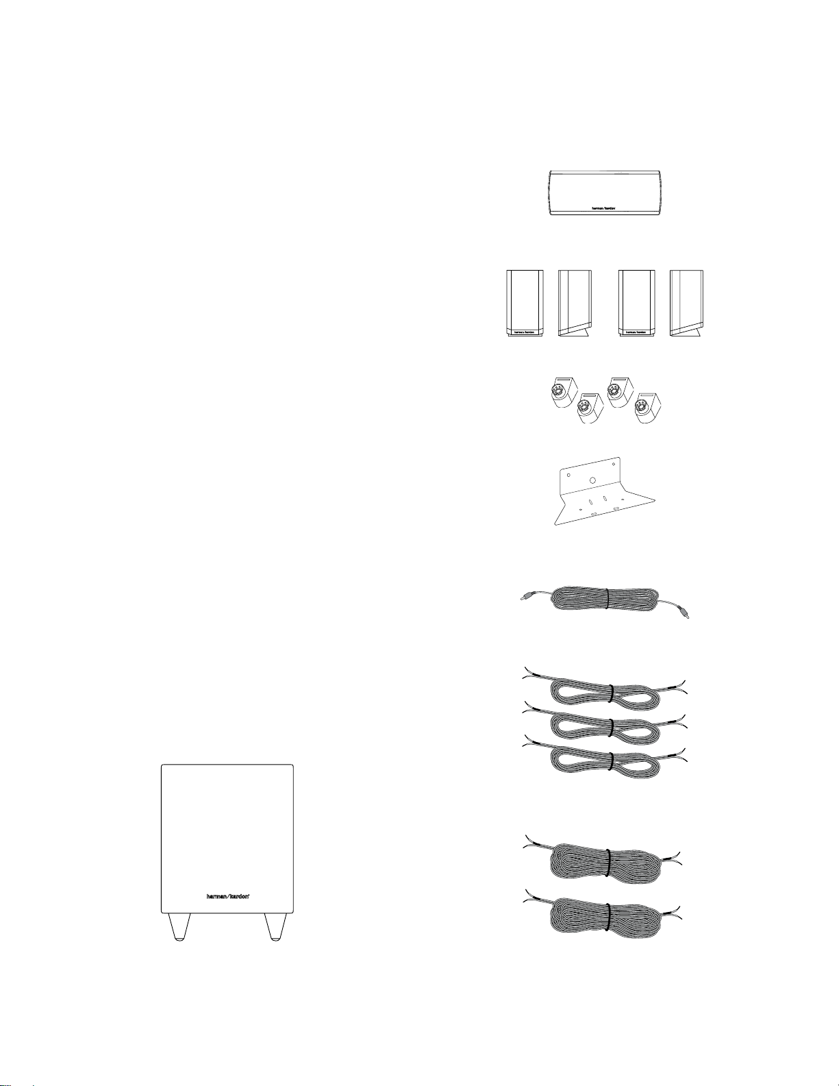
One center-channel speaker
Four satellite speakers: a front left speaker, a front right speaker and two rear surroundsound speakers (shown with included shelf stands attached).
Four wall-mount brackets for satellite speakers
One wall-mount bracket for center-channel speaker
One LFE (low-frequency effects) for connection to the subwoofer (LFE cable has purple
connectors)
Three six-meter (19.7-foot) speaker cables for connection to front satellites (red and
white) and to center speaker (green)
Included Items
One HKTS 160SUB subwoofer
2
Two 12-meter (39.4-foot) speaker cables for connection from receiver to rear surroundsound satellites (gray and blue)
Page 4
HKTS 5
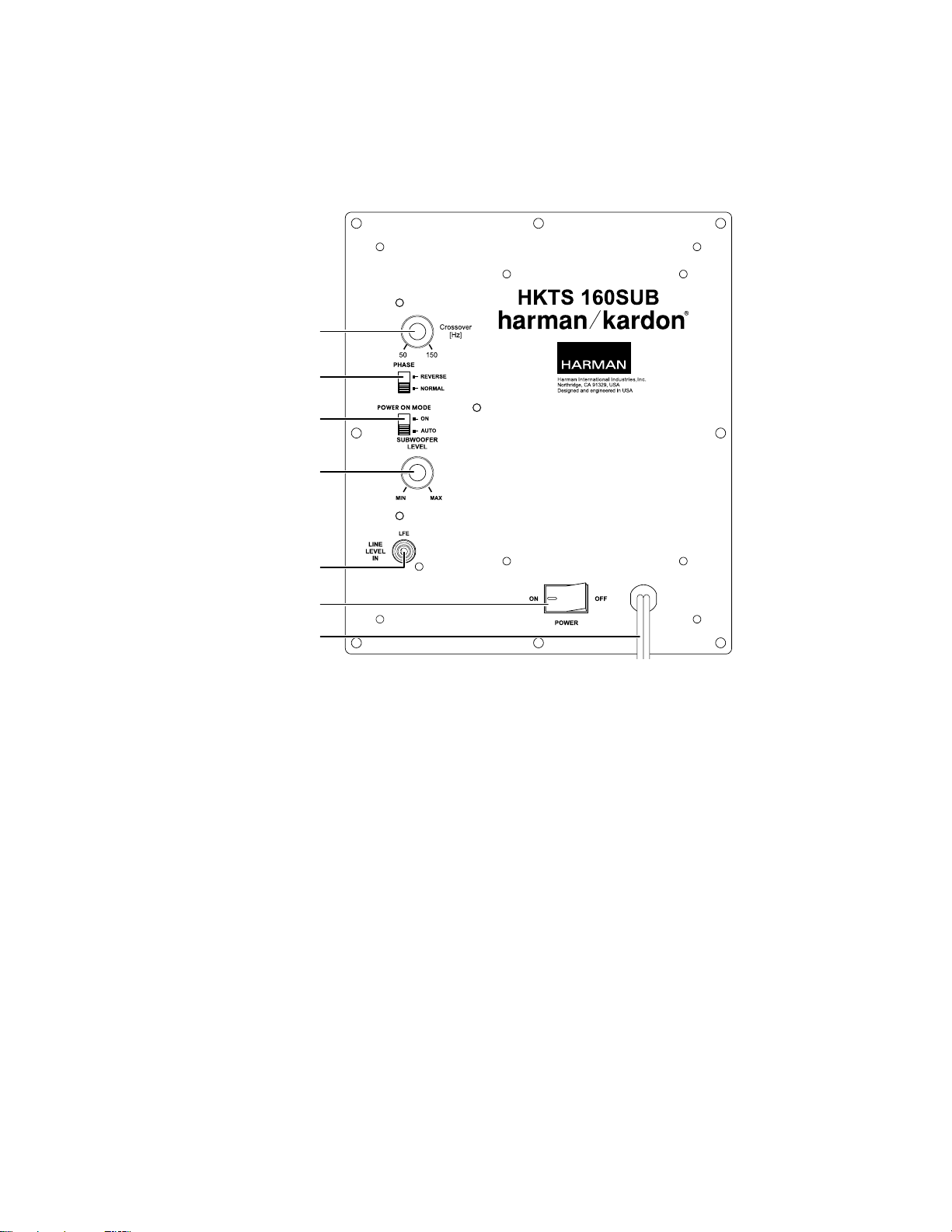
HKTS 160SUB Rear-Panel Connections
Crossover control
Phase switch
Power On Mode switch
Subwoofer Level control
HKTS 160SUB Rear-Panel Connections
Line-Level LFE connector
Power switch
Power cord
Crossover control: This knob adjusts the subwoofer's cutoff between 50Hz and 150Hz.
The higher you set the Crossover control, the higher in frequency the subwoofer will
operate and the more its bass will "overlap" that of the system's other speakers. This
adjustment helps achieve a smooth transition of bass frequencies between the subwoofer
and the system's other speakers for a variety of different rooms and subwoofer locations.
NOTE: If you have connected the subwoofer to a receiver/processor with a low-pass
filtered LFE output, set the subwoofer's Crossover control to the 150Hz positon (fully
clockwise).
Phase switch: The Phase switch determines whether the HKTS 160SUB’s piston-like
action moves in and out in phase with the satellite speakers. If the subwoofer were
to play out of phase with the satellite speakers, the sound waves produced by the
subwoofer could be canceled out, reducing bass performance and sonic impact. This
phenomenon depends in part on the relative placement of all the speakers in the room.
In most cases the Phase switch should be left in the "NORMAL" position. However, it
does no harm to experiment, and you can leave the Phase switch in the position that
maximizes bass response and impact.
Power On Mode switch: If this switch is set in the"AUTO" position and the Power switch
is set to "ON", the HKTS 160SUB will automatically turn itself on when it receives an
audio signal and will enter the standby mode once no audio signal has been received for
about 15 minutes. When this switch is set in the "ON" position, the HKTS 160SUB will
remain on whether or not it is receiving an audio signal. An LED on the HKTS 160SUB’s
top panel indicates whether the subwoofer is in the on or standby state:
•
When the LED glows white, the HKTS 160SUB is turned on.
•
When the LED is not illuminated, the HKTS 160SUB is in standby mode.
When the Power switch is set to "OFF", the LED will not be illuminated, no matter what
setting the Power On Mode switch is in.
Subwoofer Level control: Use this control to adjust the HKTS 160SUB’s volume. Turn
clockwise to increase the volume; turn counterclockwise to decrease the volume.
Line-Level In/LFE connector : Connect the subwoofer output of your receiver or preamp/
processor to this jack. The signal from this connector passes through the subwoofer's
internal low-pass crossover.
Power switch: Set this switch in the "ON" position to turn the HKTS 160SUB on. The
subwoofer will then either be on or in standby mode, depending on the setting of the
Power On Mode switch.
Power cord (non-detachable): After you have made and verified all subwoofer and
speaker connections described in this manual, plug this cord into an active, unswitched
electrical outlet for proper operation of the HKTS 160SUB. DO NOT plug this cord into the
accessory outlets found in some audio components.
3
Page 5
HKTS 5
HKTS 5
Speaker Placement and Mounting Options
Speaker Placement
Color-Coding System
The HKTS 5 uses the CEA color-coding system to make setting up your home theater
speaker system as easy as possible. Your system includes a set of colored stickers that
may be placed near the speaker terminals of each of the four satellite speakers according
to the key below. It doesn’t matter which satellite speaker is used for any of the front
or rear positions. (The center speaker and powered subwoofer are already color-coded
for you.)
Speaker Position Wire Color Band
Front Left White
Front Right Red
Center Green
Surround Left Blue
Surround Right Gray
Subwoofer Purple
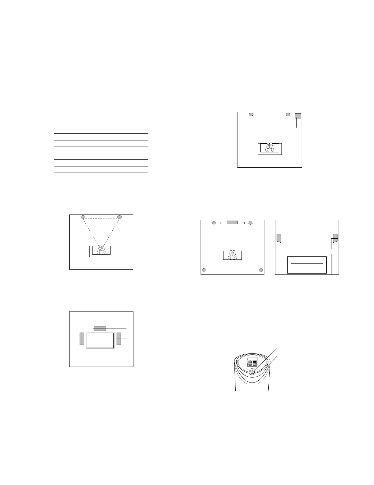
Front Speakers
Place the front speakers the same distance from each other as they are from the listening
position (the place where you'll be when you listen to the HKTS 5). They should be placed
at about the same height from the floor as the listener’s ears will be. They also can be
angled toward the listener.
White Red
Subwoofer
The low-frequency sound reproduced by the subwoofer is mostly omnidirectional, and
this speaker may be placed in a convenient location in the room. However, the best
reproduction of bass will be heard when the subwoofer is placed in a corner along the
same wall as the front speakers. Experiment with subwoofer placement by temporarily
placing the subwoofer in the listening position and moving around the room until the bass
reproduction is best. Place the subwoofer in that location.
White Red
Purple
Surround Speakers
Place the two surround speakers slightly behind the listening position. Ideally, they should
face each other and be at a level higher than the listeners’ ears. If that is not possible,
they may be placed on a wall behind the listening position, facing forward. The surround
speakers should not call attention to themselves. Experiment with their placement until
you hear a diffuse, ambient sound accompanying the main program material heard in
the front speakers.
White
Green Red
Center Speaker
The center speaker should be placed slightly behind (farther away from the listener) the
front left and right speakers. Its center should be no more than 55 cm (2 feet) above or
below the tweeters of the front left and right speakers. It is often convenient to set the
center speaker on top of the television set, as shown in the drawing.
Green
0 – 55cm
White Red
1.5 – 1.85m
Blue Gray
Mounting Options
You can place the satellite and center speakers on shelves using their built-in
stands, or you can wall-mount them using the supplied hardware.
Wall-Mounting the Satellites
1. Remove the black shelf stand from the bottom of the speaker by unscrewing the bolt.
Store the shelf stand and bolt in a safe place in case you need them in the future.
1. Remove Bolt
2. Remove Stand
2. Determine the locations for the speakers. If possible, position the speakers so that
the mounting screws (not included; use size #8) can be installed directly into a wall
stud. If that is not possible, use optional wall anchors that are rated to support at
least 25 lb (11.3kg) and are appropriate for the construction and materials of your
wall. The customer is responsible for the proper selection and use of mounting
hardware, available through hardware stores, to wall-mount the speakers
properly and safely.
4
Page 6
HKTS 5
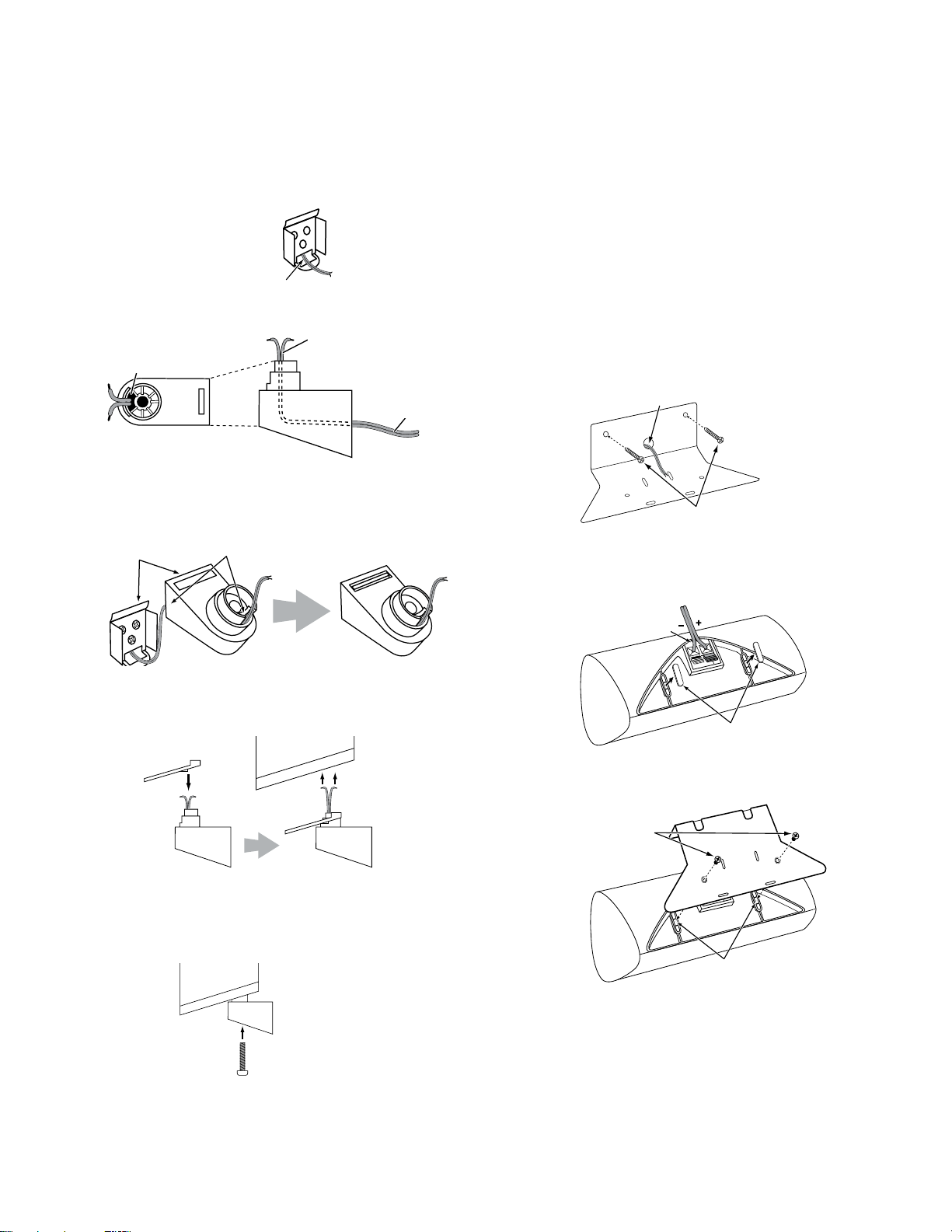
Mounting Options
3. Bring the speaker cable through the wall-bracket attachment plate, and mount the
attachment plate on the wall in the desired location.
Bring Speaker Cable
Through Opening
4. Thread the speaker cable through the arc-shaped opening on the top of the mounting
bracket, not the screw hole.
Bring Speaker Cable
Through Arc-Shaped
Opening
Overhead View
Side View
Cable to
Speaker
Cable from
Wall Plate
5. Attach the mounting bracket to the wall plate by inserting the tab at the top of the
attachment plate into the slot on top of the bracket and snapping the bracket onto
the attachment plate.
Insert Tab into Slot
and Snap Bracket
onto Plate
Feed Cable Through
Mount and out of
Opening
You can pivot the wall-mounted speaker from side to side; however, attempting to tilt it
up or down will damage the bracket and possibly the wall, which would not be covered
by your warranty.
Wall-Mounting the Center Speaker
1. Determine the location for the speaker. If possible, position the speaker so that one
of the mounting screws (not included; use size #10) can be installed directly into a
wall stud. If that is not possible, use optional wall anchors that are rated to support
at least 25 lb (11.3kg) and are appropriate for the construction and materials of your
wall. The customer is responsible for the proper selection and use of mounting
hardware, available through hardware stores, to wall-mount the speaker
properly and safely.
2. Bring the speaker cable through the wall-bracket attachment plate as shown, and
mount the attachment plate on the wall in the desired location.
Bring Cable Through
Opening
Use Mounting Hardware Appropriate
for Wall Construction and Materials
3. Remove the rubber pads from the foot rests on the bottom of the center speaker
and connect the speaker leads to the terminals on the underside of the speaker.
Remember to observe the correct polarity.
Connect
Cable
6. Fit the terminal cover onto the bracket as shown in the illustration below, then
connect the speaker leads to the terminals on the underside of the speaker.
Remember to observe the correct polarity.
Terminal Cover
Connect Cable Leads
to Speaker Terminals
Mounting Bracket
Side View
7. Fit the terminal cover into the opening on the underside of the speaker so that it is
flush against the speaker and covers the terminals. Insert the supplied long bracket
bolt up through the bottom of the bracket and terminal cover, and screw it into the
threaded insert on the underside of the speaker. The bolt should be snug but not so
tight as to prevent the speaker from pivoting on the bracket.
Fit Terminal Cover
into Recess on
Speaker Bottom
Attach Speaker
to Bracket Using
Long Bolt
Remove Pads
4. Use the supplied screws to attach the speaker to the wall-mount bracket. The screws
thread into the center foot-rest openings that were exposed when you removed the
rubber pads in the previous step.
Use Supplied Screws
to Attach Speaker to
Bracket
Thread Screws into
Center Openings
5
Page 7

HKTS 5
Speaker Connections
Speaker Connections
IMPORTANT NOTE: Before making speaker connections, be certain that your receiver or
audio power amplifier is turned off and preferably unplugged from its AC power source.
Do not connect the HKTS 160SUB subwoofer to an AC power source until you have made
all speaker-wire connections.
Speakers and other electronics have corresponding (+) and (–)
terminals. Most makers of electronics, including harman kardon
engineers, use red to denote the (+) terminal and black for the
(–) terminal.
Newer harman kardon receivers conform to the CEA standard and
therefore use a color other than red or black for the (+) terminal to indicate some speaker
positions: e.g., surround left.
Although the HKTS 5 system has red and black collars on the individual speaker terminals
to denote the positive and negative connections, your system includes a colored band on
Front Left Speaker Cable
(White Bands)
Center Speaker Cable
(Green Bands)
the positive lead at both ends of every speaker cable and a matching colored sticker for
each of the four satellite speakers, conforming to the key on page 4. The center speaker
has a green (+) terminal, and the subwoofer has a purple SUB input jack. This system is
intended to help you ensure that the speaker in each location is connected to the correct
terminals on your receiver or amplifier.
The (+) lead of the speaker wire is indicated with a stripe and has the colored band
corresponding to the speaker’s position. It is important to connect all speakers identically:
(+) on the speaker to (+) on the amplifier and (–) on the speaker to (–) on the amplifier.
With the advent of multichannel surround-sound systems, connecting all of the speakers
in your system with the correct polarity remains equally important in order to preserve
the proper ambience and directionality of the sound.
To connect the supplied speaker wires to the satellite and center speaker terminals
located on the bottom of each speaker, press the red or black tab, insert the bare end
of the wire into the hole, and release the tab. Gently tug on the wire to make sure that
it is fully inserted.
Front Right Speaker Cable
(Red Bands)
SURROUNDFRONT CENTER
+–
+– +–
RIGHT
LEFT
+–
+–
+–
Receiver
Surround Left Speaker Cable
Connecting the Subwoofer
Use the LFE (purple) connector to connect the HKTS 160SUB’s Line-Level LFE In
connector to the dedicated subwoofer output (or LFE output) of your receiver or preamp/
processor. If the receiver or preamp/processor has a low-pass filter on the subwoofer
output, set the subwoofer's Crossover Control to maximum (150 Hz).
Connect each satellite speaker and the center speaker to the corresponding speaker
terminals on your receiver or amplifier.
6
(Blue Bands)
+–
SUB
LFE OUT
Surround Right Speaker Cable
HKTS 160SUB
Subwoofer
LFE Cable
(Purple Ends)
(Gray Bands)
In your receiver or preamp/processor’s setup menu, configure the receiver or preamp/
processor for “Subwoofer ON,” and set the front, center and surround speakers to
“Small.” After you have made and verified all connections, plug the HKTS 160SUB’s AC
Power cord into an active AC outlet.
Page 8

HKTS 5
Operation
Turning the Subwoofer On and Off
Set the HK TS 160SUB’s Power switch to the "ON" position.
•
If the Power On Mode switch is set to "AUTO", the HKTS 160SUB will automatically
turn itself on when it receives an audio signal, and it will go into standby mode
when it has received no audio signal for 15 minutes. The subwoofer’s LED will
glow white when the subwoofer is on and will not be illuminated when the
subwoofer is in standby.
•
If the Power On Mode switch is set to "ON", the HKTS 160SUB will remain on at
all times. The HKTS 160SUB’s LED will glow white.
If you will be away from home for an extended period of time, or if you will not be using
the subwoofer for an extended period, switch the Power switch to the "OFF" Position.
Subwoofer Adjustments: Volume
Use the Subwoofer Level control to set the HKTS 160SUB’s volume. Turn the knob
clockwise to increase the subwoofer’s volume; turn the knob counterclockwise to
decrease the subwoofer’s volume.
Subwoofer Adjustments: Phase
The Phase switch determines whether the HKTS 160SUB’s piston-like action moves
in and out in phase with the satellite speakers. If the subwoofer were to play out of
phase with the satellite speakers, the sound waves produced by the subwoofer could be
canceled out, reducing bass performance and sonic impact. This phenomenon depends
in part on the relative placement of all the speakers in the room.
Although in most cases the Phase switch should be left in the "NORMAL" position,
there is no absolutely correct setting for the Phase switch. When the HKTS 160SUB
is properly in phase with the satellite speakers, the sound will be clearer and have
maximum impact, making percussive sounds like drums, piano and plucked strings
sound more lifelike. The best way to set the Phase switch is to listen to music that
you are familiar with and set the switch in the position that gives drums and other
percussive sounds maximum impact.
Speaker Connections and Operation
Subwoofer Adjustments: Crossover
The subwoofer’s Crossover control adjusts the subwoofer’s cutoff between 50Hz and
150Hz. The higher you set the Crossover control, the higher in frequency the subwoofer
will operate and the more its bass will “overlap” that of the system's other speakers.
This adjustment helps achieve a smooth transition of bass frequencies bet ween the
subwoofer and the other speakers for a variety of different rooms and subwoofer
locations.
To set the Crossover control, listen for the smoothness of the bass. If the bass seems
too strong at certain frequencies, try a lower Crossover control setting. If the bass
seems too weak at certain frequencies, try a higher Crossover control setting.
7
Page 9

HKTS 5
Troubleshooting
Troubleshooting
This unit is designed for trouble-free operation. Most problems users encounter are due to operating errors. So if you have a problem, first check this list for a possible solution.
If the problem persists, consult your authorized harman kardon service center.
Problem Solution
If no sound comes from any of the speakers: • Check that the receiver/amplifier is on and a sound source is playing.
• Make sure that all wires between the receiver/amplifier and the soundbar are
connected properly.
• Make sure that none of the speaker wires is frayed, cut or punctured.
• Review the proper operation of your receiver/amplifier.
If there is no sound coming from one speaker: • Check that the balance control on your receiver/amplifier is not set all the way
If there is no sound coming from the center speaker: • Check your receiver/amplifier’s speaker-setup procedure to make sure that
If there is no sound coming from the surround speakers: • Check your receiver/amplifier’s speaker-setup procedure to make sure that the
If there is no sound coming from the subwoofer: • Check that the subwoofer’s Power cord is plugged into a working AC outlet.
If the system plays at low volumes but shuts off as volume is increased: • Make sure that all wires between the receiver/amplifier and the soundbar are
You can find additional troubleshooting information in the FAQs link on the Support page at www.harmankardon.com.
8
to one channel.
• Check your receiver/amplifier’s speaker-setup procedure to make sure that the
speaker in question has been enabled and that its volume level has not been
turned all the way down.
• Make sure that all wires between the receiver/amplifier and the speaker
terminals are connected properly.
• Make sure that the speaker wires are not frayed, cut or punctured.
the center speaker has been enabled and its volume level has not been turned
all the way down.
• Make sure that all wires between the receiver/amplifier and the center speaker
terminals are connected properly.
• Make sure that the speaker wires are not frayed, cut or punctured.
• If your receiver is operating in Dolby
center speaker is not set to “Phantom.”
surround speakers have been enabled and their volume levels have not been
turned all the way down.
• Make sure that all wires between the receiver/amplifier and the surround
speaker terminals are connected properly.
• Make sure that the speaker wires are not frayed, cut or punctured.
• Review proper operation of your receiver/processor and its surround-sound features.
• Make sure that the movie or TV show you’re watching has been recorded in a
surround-sound mode. If it has not, check to see if your receiver/amplifier has
a different surround-sound mode that you can use.
• Review the operation of your DVD player and the DVD jacket to make sure that
the DVD features the desired Dolby Digital or DTS
that you have properly selected that mode using both the DVD player’s menu
and the disc’s menu.
• Check that the subwoofer’s Power switch is in the "ON" position.
• Check that the Subwoofer Level control is not turned all the way down (fully
counterclockwise).
• Check the audio-cable connection between your receiver/processor and the
subwoofer.
• Check your receiver/amplifier’s speaker-setup procedure to make sure that
the subwoofer has been enabled and that its volume level has not been turned
all the way down.
connected properly.
• Make sure that none of the speaker wires is frayed, cut or punctured.
• If you have an additional pair of front speakers connected to your receiver/
amplifier, make sure that you’re not operating the system below the receiver/
amplifier’s minimum impedance requirements. Check the receiver/amplifier’s
documentation for more information.
®
Pro Logic® mode, make sure that the
®
surround-sound mode and
Page 10

HKTS 5
HKTS 5
Specifications
Specifications
HKTS 5 System
Frequency response: 45Hz – 20kHz (–6dB)
Satellites Center HKTS 160SUB Subwoofer
Recommended power: 10 – 80 watts 10 – 80 watts Power requirement: AC 120V, 60Hz (USA)
Impedance: 8 ohms nominal 8 ohms nominal
Sensitivity: 86dB @ 1 watt/1 meter 86dB @ 1 watt/1 meter Power consumption: <0.55W (120V & 230V) standby
Tweeter: One 1/2" (12mm) dome One 3/4" (19mm) dome Amplifier power: 60 watts RMS
Midrange: One 3" (75mm) driver Dual 3" (75mm) drivers Low-frequency transducer: 8" (200mm) cone sealed enclosure
Dimensions (H x W x D): 6-5/8" x 3-15/16" x 3-5/8"
(167mm x 100mm x 92mm)
Weight: 1.45 lb (0.7kg) each 2..5 lb (1.1kg) Weight: 17.0 lb (7.7kg)
4" x 9-1/2" x 3-5/8"
(102mm x 241mm x 92mm)
Dimensions (H x W x D): 13-29/32" x 10-1/2" x 10-1/2"
AC 220V – 240V, 50/60Hz (EU)
85W - 1.0A (120V) maximum
85W - 0.68A (230V) maximum
(353mm x 267mm x 267mm)
9
Page 11

HARMAN Consumer, Inc.
8500 Balboa Boulevard, Northridge, CA 91329 USA
© 2012 HARMAN International Industries, Incorporated. All rights reserved.
Harman Kardon is a trademark of HARMAN International Industries, Incorporated,
registered in the United States and/or other countries. Dolby, Pro Logic and the
double-D symbol are registered trademarks of Dolby Laboratories. DTS is a
registered trademark of DTS, Inc. CEA is a registered trademark of the Consumer
Electronics Association.
Features, specifications and appearance are subject to change without notice.
Part No.
www.harmankardon.com
Page 12

Page 13

Page 14

1
2
3
4
5
6
7
8
HKTS160 SUB DV_0609
A A
CN1
+26V
1
GND
23
19
20
21
22
24
28
25
27
26
29
30
31
32
33
34
35
36
1
2
3.96
IC1
VL
GNDREF
GNDR1
VDD
VDD
CONFIG
TWARN
PWRDN
FAULT
TRI-STATE
IN-LA
IN-LB
IN-RA
IN-RB
VSS
VSS
VCC SIGN
VCC SIGN
GND SUB
STA512B
GND
59
GND
VDD
NC
FILTER_PLL21GNDA
22
58
23
GND
56
LRCKO
SDO_1257SDO_34
STA309A
CKOUT
VDDA
25
24
+3.3V
R1
2K
C2104
54
55
50
49
51
52
NC
GND53VDD
EAPD
BICKO
OUT1_B
OUT1_A
EAPD#
IC2
OUT2_A
OUT2_B
GND
VDD
OUT3_A
OUT3_B
OUT4_A
OUT4_B
OUT5_A
OUT5_B
GND
VDD
OUT6_A
OUT6_B
R3
NC
48
47
46
NC
45
44
43
42
41
40
39
38
37
NC
36
35
34
33
EAPD
3
R4
NC
Q1
NC
1 2
GND
C10
+
10uF
C13
104
+3.3V
CH
5A
CH5B
C18
104
+3.3V
+3.3V
TWARN
EAPD
B15
BEAD-600
GND
R5
10K
R11
10K
GND
C15
104
CH5B
C3
104
C6
104
CH5A
GND
VDD
GND
NC
26
OUT7_A32OUT7_B31OUT8_A30OUT8_B
28
27
29
B2
GND
C33
104
+3.3V
SGND
BEAD-600
C27
C28
104
22uF
B3
BEAD-600
+3.3V
C29
104
GND
GND
C23
104
C24
104
+3.3V
+3.3V
C1104
R2
10K
NC
GND
GND
+3.3V
+3.3V
C20
104
C25
R15
R17
NC
309A_PWRDN
C4
1N2
GND
1
MVO
2
GND
3
VDD
4
GND
5
NC
6
SDI_78
7
SDI_56
8
SDI_34
9
SDI_12
10
LRCKI
11
BICKI
12
VDD
13
GND
14
NC
15
RESET
16
PLLB
0R16
OPT
0
C26NC
C30
1N2
GND
100PF
62
63
61
64
60
NC
PWDN
SDO_56
SDO_78
XTI
SDA18SCL19SA
20
17
R20
3K3
C31
C32
100PF
SGND
309A_PWRDN
B B
R7
+3.3V
R8 0
GND
C11 104
GND
SD0
GND
MCLK
SDA
SCL
LRCK
BICK
C19
104
RESET#
R12 0
R13 0
R14 0
R18
R19
GND
C22
47P
0
0
SD0
LRCK
BICK
+3.3V
C C
RESET#
MCLK
SDA
SCL
BEAD
B1
OUT 1A
OUT 1A
OUT 1B
OUT 1B
OUT 2A
OUT 2A
OUT 2B
OUT 2B
VCC 1A
VCC 1B
VCC 2B
VCC 2A
PGND 1A
PGND 1B
PGND2A
PGND2B
PVCC_S
NC
18
17
16
11
10
9
8
3
2
15
12
7
4
14
13
6
5
C79
GND
GND
SUB ++
SUB--
1U/50V X7R
1U/50V X7R
C80
GND
1U/50V X7R
L1
22UH
C7
330PF/50V
R9
22R
R32
22R
C77
330PF/50V
L2 22UH
C16
GND
C21
1U/50V X7R
C5 104/50V X7R
GND
C14 104/50V X7R
+
C17
1000U/63V
104/50V X7R
R6
6.2R
R10
6.2R
104/50V X7R
PVCC_S
PVCC_S
SUB +
SUB-
C8
C12
C9
684/63V
CN2
1
2
4 OHM
D D
Title
MAIM P CB
MAIM P CB
MAIM P CBMAIM P CB
Number RevisionSize
A3
Date: 2012/6/9 Sheet of
1
2
3
4
5
6
File: D:\2011\..\HKTS160_AMP_DV_0609.SCHDOCDrawn By:
7
Allen_kao
8
Page 15

1
JK1
RCA1P
A A
B B
C C
D D
GND
C78
100P
GND
C34
2
1
GND
CN6
CON2.5-4
1
+
22u/16
C37
220P
GND GND GND
3.3VAD
C60
104
C62
104
C48
C53
-3.3V
STB
B5
BEAD-600
C46
22uF/16V
22u/16
R53
68K
GND
+
22u/16
+
B8
BEAD-600
GND
B9
BEAD-600
+
180P
GND
C54
B
R52
100K
180P
S D
R49
100K
MCU3.3V MCU3.3V
R36
4.99K 1%
R39
49.9K 1%
1
2
3
4
309 POWER
2
R23 10K
C47
104
10
9
8
7
6
C55
1uF/25V
-3.3VA
Q3
AP2305GN
2
G
CS5343
+
C56
GND GND
C61
104
GND
+3.3VA
C65
104
GND
D3S
G
1
GND
CE
Q4
2N3904
2
VA
GND
AINR
VQ
AINL
C57
104
SW3.3V
C72
104
C75
22uF/16V
R21 10K
C35 100P
6
-
5
+
BEAD-600
SDOUT
MCLK
C58
104
B10
BEAD-600
B13
+
BEAD-600
GND
B4
SCLK
LRCK
FILT+
O
U1B
TS912
GND
GND
3
R22 100K
C36 100P
-3.3VA
104
7
R25 5K
3
1
VR1
1KA
D3.3V
R33
10K
U2
1
2
3
4
5
+
C59
1uF/25V
MCU3.3V
C63
104
+3.3V+3.3VA
C73
104
GND
2
3
2
+3.3VA
R34
100
SD0
R35
R37
R38
SD0
100
BICK
BICK
100
LRCK
LRCK
100
MCLK
MCLK
3
GND
C38
B-
1
B+
U1A
8 4
TS912
C43 104
+
22u/16
C45
G LED R LED
GND
R46
10K
C40
22u/16
MCU3.3V
3
Q2
2N3904
MCU3.3V
C69
104
4
5
HKTS160 SUB DV_0609
R26 10K
+
R31
50K
GND GND
CN3
123
R24
R27
2.7K
2.7K
21
21
GNDGND
B11
BEAD-600
C70
104
C71
18P
4
ZD1
3.3V
1 2
R47
3
10K
Q5
2N3904
R50
100K
1 2
XL1
12.288MHZ
2 4
U6
3 5
NC7SZ04M5X_NL
AUTO ON
309A_PWRDN
R51
10K
GND
EAPD#
B12 120R
C67
18P
GND
OPT
G2 G1
GND GND
R28 10K
MCU3.3V
10uF/16V
EAPD#
TXD
MCLK
POWER GOOD
309A_PWRDN
MCLK
C68
POWER ON MODE PHASE
MCU3.3V
C49
+
R40
10K
1
2
3
4
R43
0
5
6
7
STB
8
G LED
9
10
GND
5
6
ONAUTO
SW1
3
5 641 2
PWR
PWR MODE PHASE
MCU3.3V
GND
U3
RST
RxD/P3.0
TxD/P3.1
XTAL2
XTAL1
INT0/P3.2
INT1/P3.3
T0/P3.4
T1/P3.5
GND
TXD
C50
104
GND
MCU3.3V
B14
BEAD
C51
104
P1.7/SCLK
P1.6/MISO
P1.5/MOSI
P3.7/CEX0/PWM0
MPC82L52AT
CN4
1
2
3
4
ISP
Vol
C39
104
X-OVER Control
P1.4/SS
GND
+
10uF/16V
VCC
P1.3
P1.2
P1.1
P1.0
MCU3.3V
2
C52
GND
6
20
19
18
17
16
15
14
13
12
11
31
VR2
100KB
MCU3.3V
R41
10K
RESET#
AUTO ON
309 POWER
PWR MODE
PHASE
Vol
R LED
R42
10K
B6
BEAD-600
RESET#
MCU3.3V
Title
A3
Date: 2012/6/9 Sheet of
File: D:\2011\..\HKTS160_INPUT_DV_0609.SchDocDrawn By:
B7
BEAD-600
R45
100
SCL
SDA
3
1
GND
MAIM P CB
MAIM P CB
MAIM P CBMAIM P CB
Number RevisionSize
7
SCL
SDA
GND
2
RST
VCC
VSS
U4
STM809-2.93V
7
G2 G1
GND GND
5 641 2
R29 10K
MCU3.3V
J1
1
2
3
4
JH-8M3
POWER GOOD
8
REVERSENORMAL
SW3
3
PHASE
Allen_kao
8
Page 16

1
1
2
2
3
3
4
4
5
5
6
6
7
7
8
8
D D
C C
B B
A A
Title
Number RevisionSize
A3
Date: 2012/9/20 Sheet of
File: D:\A99004\..\HKTS5SUB PSU Main .SchDocDrawn By:
CX1
0.33/250V/ X2
ZNR1
TVR10471
TH1
SCK048
42
31
LF1
YCILF1810PD
CX2
0.22/250V/ X2
1
3
2
CN1
CON3.96-3P2C
F1
V+
1
AC
2
AC
3
V-
4
BR1
GBU406
+
C1
120uF/200V
+
C4
120uF/200V
PGND
R1
1M/1206
R4
1M/1206
R5
1M/1206
R8
1M/1206
1 3
J2
42
31
LF2
YCILF1810PD
DC320V
CY1
471/Y1
CY2
471/Y1
AC1
AC2
AC2A
+
C21
680uF/50V
SGND1
R32
56/1206
C23
221/1206/200V
R37
56/1206
C24
221/1206/200V
+VH1
1
2
CN4
CON3.96-2
R33
68K/1206
G
DS
Q6
NDF9N60
1 3
2 4
CT1
UU-9.8
1 2
C28
105/250V
R39
22/1206
1 2
D11
1N4148/0805
R31
22/0.25W
1 2
D14
1N4148/0805
C20
104/1206/100V
A
12
J10
SGND1 SGND1 SGND
R34
68K/1206
AC2A
1
2
3
D8
ER1002CT
+
C22
680uF/50V
1
5
11
1
6
10
7
9
11
12
3
4
T2
ERL-28V
PGND
R38
10K/0.125W
R40
10K/0.125W
1 2
J4
SGND1
12
J8
SGND2
L2
170uH
9
8
4
2
3
1
DT1
EEL-16
B
CE
Q2
MMBT4401
1 2
ZD2
15V
R14
470/1206
DC320V
12VS
R28
30/1206
R29
OPEN/1206
C18
104/0805
R26
10K/0805
R30
8.2K/0805
+
C19
10uF/50V
A
C16
104/0805
3
21
Q4
2N3904
12
3 Q3
2N3906
R17
10K/0805
R25
0/0805
C12
102/0805
1
D6
SF16
SGND2
SGND2
SGND2
R23
51/1W
C30
102/1KV
15VS1
12
3
Q9
MMBT2907
12
D12
1N4148/0805
12
D13
1N4148/0805
12
3
Q10
MMBT2907
+VH1
1
2
3
4
5
6
7
8
CN3
CON2.0-8
FB
OA
OB
SD1
12VS
SGND2
R36
39K/1206
C25
474/1206
R41
22K/1206/1%
FB
OA
OB
CY3
222/Y1
SGND1
12
J6
SGND2
G
DS
Q7
NDF9N60
R7
1.2K/1206/1%
230Vac:2.5A/250V
120Vac:4.0A/250V
P0F101 P0F102
P0F101
P0F101
P0F102 P0TH102
P0F102 P0TH102
P0TH101 P0TH102
P0TH101
P0TH101
N0AC1
N0AC1
N0DC320V
P0CN101
P0CN101
P0CN101
P0CN102
P0CN102
P0CN102
P0CN103
P0CN103
P0CN103
P0ZNR102
P0ZNR102
P0ZNR101 P0ZNR102
P0ZNR101
P0ZNR101
P0R802
P0R802
P0R801 P0R802
P0R501 P0R502
P0R501 P0R801
P0R501 P0R801
P0R502
P0R502
P0LF104
P0LF104
P0CX102
P0CX102
P0CX101 P0CX102
P0CX101
P0CX101
P0LF102
P0LF102
P0LF102
P0LF103 P0LF104
P0LF103 P0LF204
P0LF103 P0LF204
P0LF101
P0LF101
P0LF101
P0CX202
P0CX202
P0CX201 P0CX202
P0CX201
P0CX201
P0LF202
P0LF202
P0LF202
P0LF203 P0LF204
P0LF203
P0LF203
P0LF201
P0LF201
P0LF201
P0CY102
P0CY102
P0CY101 P0CY102 P0CY201 P0CY202
P0CY101 P0CY202
P0CY101 P0CY202
P0CY201
P0CY201
P0BR104
P0BR104
P0BR104
N0AC2
N0AC2
P0BR102
P0BR102
P0BR102
P0BR103
P0BR103
P0BR103
P0J201
P0J201
P0J201
P0BR101
P0BR101
P0BR101
P0J203
P0J203
P0J203
P0C101 P0C102 P0C401 P0C402
P0C101
P0C101
P0C102 P0C401
P0C102 P0C401
P0C402
P0C402
N0AC2A
P0R102
P0R102
P0R101 P0R102 P0R401 P0R402
P0R101 P0R402
P0R101 P0R402
P0R401
P0R401
N0DC320V
N0DC320V
P0Q60D
P0Q60D
P0Q60D
P0Q60S
P0Q60S
P0Q60S
N0OA
N0OA
P0DT109
P0DT109
P0DT109
P0DT104
P0DT104
P0DT104
P0R3101 P0R3102
P0R3101
P0R3101
P0R3102
P0R3102
P0D1101
P0D1101
P0D1101
P0Q903
P0Q903
P0Q903
P0D1102
P0D1102
P0D1102
P0Q901
P0Q901
P0Q901
P0Q902
P0Q902
P0Q902
P0D1201
P0D1201
P0D1201
P0R3802
P0R3802
P0R3801 P0R3802
P0R3801
P0R3801
P0Q60G
P0Q60G
P0Q60G
P0DT102
P0DT102
P0DT102
N0OB
N0OB
P0DT108
P0DT108
P0DT108
P0DT103
P0DT103
P0DT103
P0DT101
P0DT101
P0DT101
P0R3901 P0R3902
P0R3901
P0R3901
P0R3902
P0R3902
P0D1401
P0D1401
P0D1401
P0Q1003
P0Q1003
P0Q1003
P0D1202
P0D1202
P0D1202
P0D1402
P0D1402
P0D1402
P0Q1001
P0Q1001
P0Q1001
P0Q70G
P0Q70G
P0Q70G
P0Q70D
P0Q70D
P0Q70D
P0Q70S
P0Q70S
P0Q70S
P0R4002
P0D1301
P0D1301
P0D1301
P0Q1002
P0Q1002
P0Q1002
P0R4002
P0R4001
P0R4001
P0R4001 P0R4002
P0CY301 P0CY302
P0CY301
P0CY301
P0CY302
P0CY302
N0AC2A
N0AC2A
P0CT104
P0CT104
P0CT104
P0CT102
P0CT102
P0CT102
P0C2801
P0C2801
P0C2801
P0C2802
P0C2802
P0C2802
P0CT103
P0CT103
P0CT103
P0CT101
P0CT101
P0CT101
N0A
N0A
P0R2301 P0R2302
P0R2301
P0R2301
P0C3002 P0R2302
P0C3002 P0R2302
P0C3001 P0C3002
P0C3001
P0C3001
P0T201
P0T201
P0T201
P0T206
P0T206
P0T206
P0T203
P0T203
P0T203
P0T204
P0T204
P0T204
P0T201
P0T201
P0T205
P0T205
P0T205
P0T209
P0T209
P0T2010 P0T2011
P0T2010 P0T2011
P0T207
P0T207
P0T207 P0T209 P0T2010 P0T2011 P0T2012
P0T2011 P0T2012
P0T2011 P0T2012
P0D803
P0D803
P0D803
P0D801
P0D801
P0D801
P0R3201 P0R3202
P0R3201
P0R3201
P0C2301 P0R3202 P0C2401 P0R3702
P0C2301 P0R3202 P0C2401 P0R3702
P0C2301 P0C2302 P0C2401 P0C2402
P0C2302 P0C2402
P0C2302 P0C2402
P0R3701 P0R3702
P0R3701
P0R3701
P0D802
P0D802
P0D802
P0L201 P0L202
P0L201
P0L201
P0L202
P0L202
P0C2201
P0C2201
P0C2201 P0C2202
P0C2202
P0C2202
P0C2101
P0C2101
P0C2101 P0C2102
P0C2102
P0C2102
P0J802
P0J802
P0J802
P0R3302
P0R3302
P0R3301 P0R3302
P0R3301
P0R3301
P0J1002
P0J1002
P0J1002
P0J801
P0J801
P0J801
N0+VH1
N0+VH1
P0R3402
P0R3402
P0C2002
P0C2002
P0R3401 P0R3402
P0R3401
P0R3401
P0C2001
P0C2001
P0C2001 P0C2002
P0J1001
P0J1001
P0J1001
P0CN402
P0CN402
P0CN402
P0CN401
P0CN401
P0CN401
P0CN308
P0CN308
P0CN308
P0CN307
P0CN307
P0CN307
P0CN306
P0CN306
P0CN306
P0CN305
P0CN305
P0CN305
P0CN304
P0CN304
P0CN304
P0CN303
P0CN303
P0CN303
P0CN302
P0CN302
P0CN302
P0CN301
P0CN301
P0CN301
N0FB
N0SD1
N0SD1
N0OB
N0OA
P0J602
P0J602
P0J602
P0J601
P0J601
P0J601
N012VS
N012VS
P0D1302
P0D1302
P0D1302
P0R1701 P0R1702
P0R1701
P0R1701
P0R1702
P0R1702
P0Q303
P0Q303
P0Q303
P0Q402
P0Q402
P0Q402
P0Q401
P0Q401
P0Q401
P0Q301
P0Q301
P0Q301
P0Q302
P0Q302
P0Q302
P0Q403
P0Q403
P0Q403
P0C1602
P0C1602
P0C1601
P0C1601
P0C1601 P0C1602
P0Q20E
P0Q20E
P0Q20E
P0Q20B
P0Q20B
P0Q20B
P0ZD202
P0ZD202
P0ZD202
P0ZD201
P0ZD201
P0ZD201
P0Q20C
P0Q20C
P0Q20C
P0R1402
P0R1402
P0R1401 P0R1402
P0R1401
P0R1401
P0C1202
P0C1202
P0C1201
P0C1201
P0C1201 P0C1202
N015VS1
N015VS1
N0FB
N0FB
P0C2502
P0C2502
P0R4102
P0R4102
P0R4101 P0R4102
P0C2501 P0C2502
P0C2501 P0R3602
P0C2501 P0R3602
P0R702 P0R4101
P0R702 P0R4101
P0R701 P0R702
P0R701
P0R701
P0R3601 P0R3602
P0R3601
P0R3601
P0J401
P0J401
P0J401
P0J402
P0J402
P0J402
N0+VH1
N0A
P0D601
P0D601
P0D601
P0R2801 P0R2802
P0R2801
P0R2801
P0R2802
P0R2802
P0R2901 P0R2902
P0R2901
P0R2901
P0R2902
P0R2902
P0D602
P0R2501 P0R2502 P0R2601 P0R2602
P0D602 P0R2501
P0D602 P0R2501
P0R2502 P0R2601
P0R2502 P0R2601
P0C1802
P0C1802
P0C1801
P0C1801
P0C1801 P0C1802
P0R2602
P0R2602
P0R3002
P0R3002
P0R3001 P0R3002
P0R3001
P0R3001
P0C1901
P0C1901
P0C1901 P0C1902
P0C1902
P0C1902
Page 17

1
1
2
2
3
3
4
4
D D
C C
B B
A A
Title
Number RevisionSize
A4
Date: 2012/5/30 Sheet of
File: D:\A99004\..\HKTS5SUB PSU Standby.SchDocDrawn By:
SoftS
1
FB
2
CS
3
D
4
D
5
NC
6
VCC
7
GND
8
U1
ICE3B0365J
R3
100K/0.5W
D2
UF4007
C2
222/1KV
R11
22/1206
+
C8
22uF/50V
C9
104/0805
1 2
ZD1
24V/1206
D3
1N4148
PGND
C15
102/0805
R20
2.2/0.5W
C13
105/0805
PGND
PGND
1
2
4
3
U2
K1010
1
2 3
IC1
TL432
R16
2.2K/0805
R15
200/1206
R22
10K/0805/1%
C14
104/0805
R19
0/0805
C11
102/0805
SGND
1 2
D1
SB140
R2
10/1206
R6
10/1206
C3
103/0805
+
C5
220uF/16V
L1
3uH
+
C6
100uF/16V
C7
104/0805
R10
1K/1206
SGND
R21
16K4/0.125W/1%
3.3VSB/0.1A
1
2
3
4
CN2
CON2.5-4
PS/ON
DC320V
D5
1N4148
1 2
J3
12
D9
SB140
+
C26
220uF/16V
+
C27
100uF/16V
SGND
12
3
Q8
MMBT4403
R35
100
C29
104/0805
12
ZD3
4.7V/1206
SGND
-VSB
-VSB
-VSB/0.1A
B
CE
MMBT3904
Q5
R27
510K/1206
R24
30K/1206
C17
104/1206
SGND
D7
1N4148
6
10
3
4
5
4
8
9
2
1
T1
EE-16
1 2
D4
MBR1200
+
C31
100uF/25V
+
C10
OPEN
12
3
Q1
MMBT4403
R18
5.1K/0805
R13
5.1K/0805
R12
0/0805
SGND2
-VSB/0.1A
3.3VSB/0.1A
PS/ON
SGND3
15VS
15VS
15VS1
1 2
J5
1 2
J7
1 2
J9
SGND2
1
1
1
2
CY4
102/Y1
PGND SGND
1 2
J1
C32
221/1KV
R9
47/1206
1 2
TVS
NI
R21--> 16.4K for 60W
P0CY401 P0CY402
P0CY401
P0CY401
P0CY402
P0CY402
P0J101
P0J101
P0J101
P0J102
P0J102
P0J102
P0R202
P0R202
P0R201 P0R202
P0R201
P0R201
P0R602
P0R602
N0DC320V
N0DC320V
P0101
P0101
P0101
P0201
P0201
P0201
P0J701
P0J701
P0J701
P0J702
P0J702
P0J702
P0R301 P0R302
P0R301
P0R301
P0C202
P0C202
P0T106
P0T106
P0T106
P0D101
P0D101
P0D101
P0T105
P0T105
P0C201 P0C202
P0R302
P0R302
P0C201 P0D202
P0C201 P0D202
P0D902
P0D902
P0D902
P0T103
P0T103
P0T1010
P0T1010
P0D201 P0D202
P0D201
P0D201
P0T1010
P0R601 P0R602
P0R601
P0R601
P0D102
P0D102
P0D102
P0D901
P0D901
P0D901
P0C2602
P0C2602
P0C301 P0C302 P0C501 P0C502
P0C301
P0C301
P0C302 P0C501
P0C302 P0C501
P0L101 P0L102
P0L101
P0L101
P0C502
P0C502
P0L102
P0L102
N00VSB
N00VSB
P0C601
P0C601
P0C601 P0C602
P0C602
P0C602
P0R1002
P0R1002
P0R1001 P0R1002
P0R1001
P0R1001
P0C702
P0C702
P0C701
P0C701
P0C701 P0C702
N0303VSB/001A
N0303VSB/001A
P0CN201
P0CN201
P0CN201
P0CN202
P0CN202
P0CN202
P0CN203
P0CN203
P0CN203
P0CN204
P0CN204
P0CN204
N00VSB/001A
N00VSB/001A
N0PS/ON
N0PS/ON
N00VSB
P0R3502
P0R3502
P0R3501
P0R3501
P0R3501 P0R3502
P0C2902
P0C2902
P0C2901 P0C2902
P0C2901
P0C2901
P0Q802
P0Q802
P0Q802
P0Q803
P0Q803
P0Q803
P0ZD301
P0ZD301
P0ZD301
P0ZD302
P0ZD302
P0ZD302
P0Q801
P0Q801
P0Q801
N00VSB/001A
P0C2702
P0C2702
P0C2701 P0C2702
P0C2701
P0C2701
P0C2601 P0C2602
P0C2601
P0C2601
N015VS
P0D401
P0D401
P0D401
P0T102
P0T102
P0D402
P0D402
P0D402
N015VS
P0C3101
P0C3101
P0T108
P0T108
P0T108
P0U204
P0U204
P0U204
P0U203
P0U203
P0U203
P0D301 P0D302
P0D301
P0D301
P0T109
P0T109
P0T109
P0T101 P0T104
P0T101 P0T104
P0T101 P0T102 P0T103 P0T104 P0T105
P0R1502
P0R1502
P0R1501 P0R1502
P0R1501
P0R1501
P0U201
P0U201
P0U201 P0U202
P0U202
P0U202
P0IC103
P0IC103
P0IC103
P0IC101
P0IC101
P0IC101
P0IC102
P0IC102
P0IC102
P0R1602
P0R1602
P0R1601 P0R1602
P0R1601
P0R1601
P0R1101 P0R1102
P0R1102
P0R1102
P0ZD102
P0ZD102
P0ZD102
P0C901
P0C901
P0U105
P0U105
P0U105
P0U104
P0U104
P0U104
P0J302
P0J302
P0J302
P0J301
P0J301
P0J301
P0U108
P0U108
P0U108
P0U101
P0U101
P0U101
P0U107
P0U107
P0U107
P0U102
P0U102
P0U102
P0U106
P0U106
P0U106
P0U103
P0U103
P0U103
P0C1302
P0C1302
P0C1301
P0C1301
P0C1301 P0C1302
P0C1502
P0C1502
P0C1501
P0C1501
P0C1501 P0C1502
P0R2001 P0R2002
P0R2001
P0R2001
P0R2002
P0R2002
P0D502
P0D502
P0D501
P0D501
P0D501 P0D502
P0C3201 P0C3202
P0C3201 P0R902 P0C3202
P0C3201 P0R902 P0C3202
P0C901 P0C902
P0C902
P0C902
P0R901 P0R902
P0R901
P0R901
P0ZD101
P0ZD101
P0ZD101
P0TVS02
P0TVS02
P0TVS02
P0TVS01
P0TVS01
P0TVS01
P0D302 P0R1101
P0D302 P0R1101
P0C801 P0C802
P0C801
P0C801
P0C802
P0C802
P0C3101 P0C3102
P0C3102
P0C3102
P0C1101 P0C1102
P0C1102
P0C1102
P0R1901 P0R1902
P0R1901
P0R1901
P0C1101
P0C1101
P0C1402 P0R1902
P0C1402 P0R1902
P0C1401 P0C1402
P0C1401
P0C1401
P0J902
P0J902
P0J901
P0J901
P0J901
P0J902
P0J501
P0J501
P0J501
P0R2102
P0R2102
P0R2101 P0R2202
P0R2101 P0R2202
P0R2101 P0R2102 P0R2201 P0R2202
P0R2201
P0R2201
P0J502
P0J502
P0J502
N0303VSB/001A
N015VS1
N015VS1
P0Q102
P0Q102
P0Q102
P0Q103
P0Q103
P0Q103
P0Q50C
P0Q50C
P0Q50C
P0Q50E
P0Q50E
P0Q50E
P0Q101
P0Q101
P0Q101
P0R1802
P0R1802
P0R1801 P0R1802
P0R1801
P0R1801
P0R1301 P0R1302
P0R1301
P0R1301
P0R1302
P0R1302
P0Q50B
P0Q50B
P0Q50B
P0C1702
P0C1702
P0C1701 P0C1702
P0C1701
P0C1701
P0C1001
P0C1001
P0C1001 P0C1002
P0C1002
P0C1002
P0R2702
P0R2702
P0R2701 P0R2702
P0R2701
P0R2701
P0R1201 P0R1202
P0R1201
P0R1201
P0R1202
P0R1202
P0R2401 P0R2402
P0R2401
P0R2401
P0D702
P0D702
P0D701 P0D702
P0D701
P0D701
P0R2402
P0R2402
N015VS
N0PS/ON
Page 18

1
1
2
2
3
3
4
4
D D
C C
B B
A A
Title
Number RevisionSize
A4
Date: 2012/3/7 Sheet of
File: D:\A99004\..\SG3525 Control Board(CV).SchDocDrawn By:
IN-
1
IN+
2
SYNC
3
OSC
4
CT
5
RT
6
DIS
7
SS
8
COMP
9
SD
10
OUT A
11
GND
12
Vc
13
OUT B
14
+Vi
15
Vref
16
U1
SG3525AP
R11
15.4K/0805/1%
R7
100/0805
R8
0/0805
C5
105/0805
C2
104/0805
C3
104/0805
C1
0/0805
R10
10K/0805
C6
103/0805
R3
10/0805
C4
102/0805
R4
10/0805
R2
10K/0805
R1
0/0805
FB1
1
2
3
4
5
6
7
8
CN1
CON2.0-8
FB1
OA
OB
SD
12VS
OB
OA
C7
OPEN/0805
R6
10K/0805
R5
2.49K/0805
D1
1N4148/1206
12VS
R9
OPEN/0805
R12
2K/0805
1 2
ZD1
OPEN/1206
C8
103/0805
C9
OPEN/0805
SD
R13
OPEN/0805
C
C
R14
OPEN/0805
R15
43K/0805
C10
474/0805
C
SGND
SGND
N0C
N0C
N0FB1
P0R102
P0R102
P0R101
P0R101
P0R101 P0R102
N0FB1
P0R1401
P0R1401 P0R1402
P0R1401
P0C1001 P0C1002
P0C1001
P0C1001
P0C1002 P0R1501
P0C1002 P0R1501
P0R1501 P0R1502
P0R202
P0R202
P0R201
P0R201
P0R201 P0R202
P0R1301 P0R1302
P0R1301
P0R1301
N0C
P0D102
P0D102
P0D101
P0D101
P0D101 P0D102
N012VS
N012VS
P0R402
P0R402
P0R401 P0R402
P0R1502
P0R1502
P0U101
P0U101
P0U101
P0U1016
P0U1016
P0U1016
P0R302
P0R302
P0R301
P0R301
P0R301 P0R302
P0U1015
P0U1015
P0U102
P0U102
P0U102
P0R501 P0R502
P0R501 P0R1402
P0R501 P0R1402
P0R601 P0R602
P0R601
P0R601
P0U103
P0U103
P0U103
P0R502
P0R502
P0R602
P0R602
P0U104
P0U104
P0U104
P0R702
P0R702
P0U105
P0U105
P0U105
P0U106
P0U106
P0U106
P0R701
P0U107
P0U107
P0U107
P0R701 P0R702
P0R701
P0U108
P0U108
P0U108
P0U1015
P0U1014
P0U1014
P0U1014
P0U1013
P0U1013
P0U1013
P0U1012
P0U1012
P0U1012
P0U1011
P0U1011
P0U1011
P0U1010
P0U1010
P0U1010
P0U109
P0U109
P0U109
P0R1002 P0R1302
P0R1002 P0R1302
P0C202
P0C202
P0C201 P0C202
P0C201
P0C201
P0R801 P0R802
P0R801
P0R801
N0C
P0C102
P0C102
P0C302 P0R401
P0C302 P0R401
P0C301 P0C302
P0C301
P0C301
P0R802
P0R802
P0C101 P0C102
P0C101
P0C101
P0R902
P0R902
P0R901 P0R902
P0R901 P0R1202
P0R901 P0R1202
P0ZD101
P0ZD101
P0ZD101
N0OB
N0OB
N0OA
N0OA
P0ZD102
P0ZD102
P0ZD102
N0SD
N0SD
P0CN108
P0CN108
P0CN108
P0CN107
P0CN107
P0CN107
P0CN106
P0CN106
P0CN106
P0CN105
P0CN105
P0CN105
P0CN104
P0CN104
P0CN104
P0CN103
P0CN103
P0CN103
P0CN102
P0CN102
P0CN102
P0CN101
P0CN101
P0CN101
N012VS
N0FB1
N0SD
N0OB
N0OA
P0C402
P0C402
P0C401 P0C402
P0C401
P0C401
P0R1102
P0R1102
P0R1101 P0R1102
P0R1101
P0R1101
P0C502
P0C502
P0C501 P0C502
P0C501
P0C501
P0R1001 P0R1002
P0C602 P0R1001
P0C602 P0R1001
P0C601 P0C602
P0C601
P0C601
P0C702
P0C702
P0C701 P0C702
P0C701
P0C701
P0C802
P0C802
P0C801 P0C802
P0C801
P0C801
P0R1201 P0R1202
P0R1201
P0R1201
P0C902
P0C902
P0C901 P0C902
P0C901
P0C901
 Loading...