

Page 1
User Guide
English................................
Deutsch..............................
Suomi................................
Français..............................
Italiano................................
Español...............................
Svenska..............................
.............................
Nederlands..........................
HKTS 30SAT-2
Speaker pair
Page 2
Harman Kardon
®
HKTS 30SAT-2
Introduction
Thank you for purchasing the Harman Kardon® HKTS 30SAT-2 speaker
pair, with which you’re about to begin many years of listening
enjoyment. While state-of-the-art speaker components are hard at work
within the HKTS 30SAT-2, hookup is simple. Color-coded cables make the
HKTS 30SAT-2 easy to use.
To obtain maximum enjoyment from your new speaker system, we urge
you to take a few minutes to read through this manual. It will help ensure
that the connections you make to your receiver or amplifier are correct.
If you have any questions about this product, its installation or its
operation, please contact your dealer, the best local source of information.
Description and Features
The HKTS 30SAT-2 is a pair of speakers, each of which features:
• Dual 3" (75mm) video-shielded midrange drivers
• One 3/4" (19mm) video-shielded dome tweeter
• A sealed enclosure
• A built-in, removable base
• A wall-mount bracket
• Color-coded connecting cables
The speaker cables use a color-coding system to conform to the
Consumer Electronics Association (CEA
tem minimizes confusion when you connect the speakers, especially when
you are connecting them to a Harman Kardon receiver.
Optional HTFS 3/E floor stands are available separately from your
Harman Kardon dealer.
®
) standard. This color-coding sys-
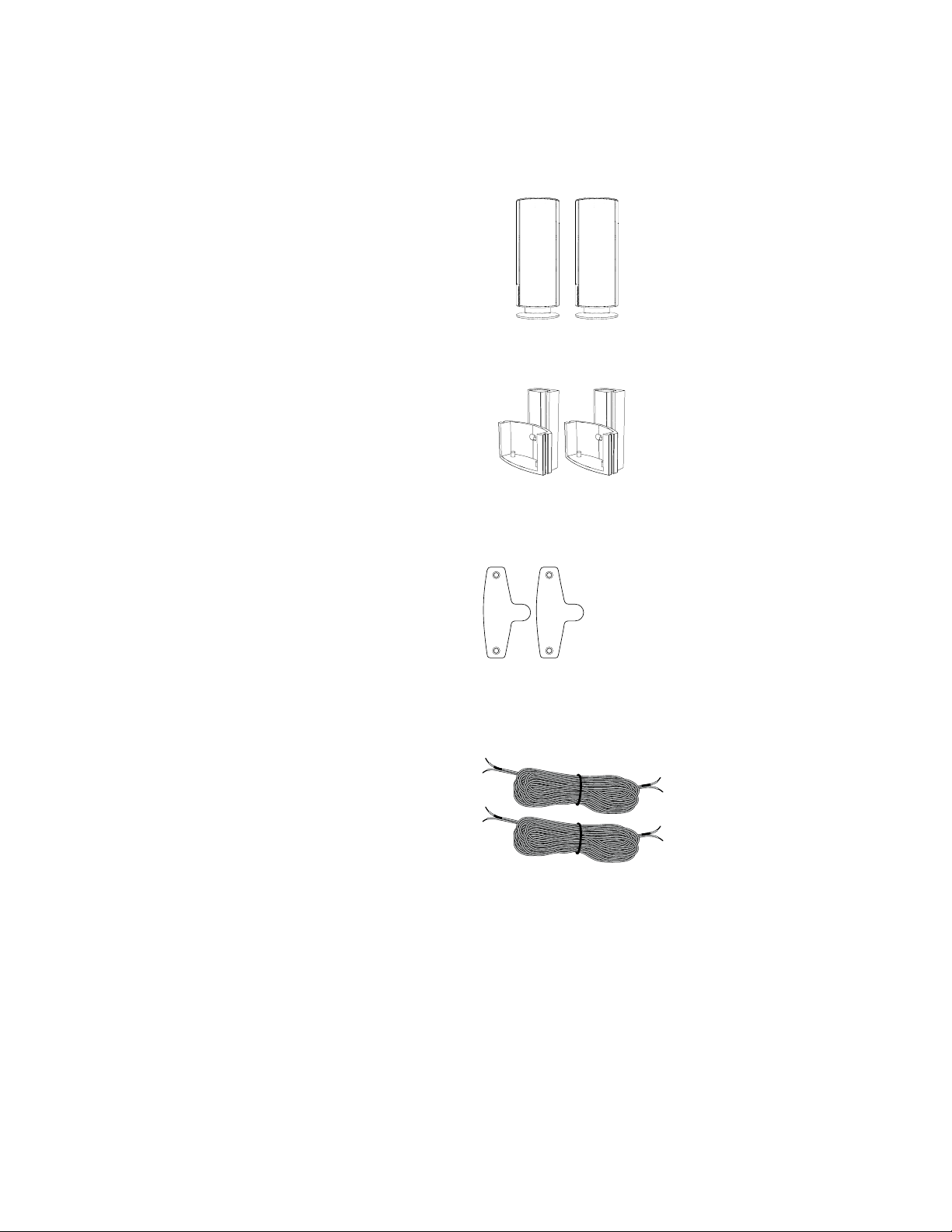
Included
Two HKTS 30SAT-2 satellite speakers
Two wall-mount brackets
Two metal stop plates and screws
Two 10-meter (32.8-foot) speaker cables
(brown and tan color bands)
2
Page 3
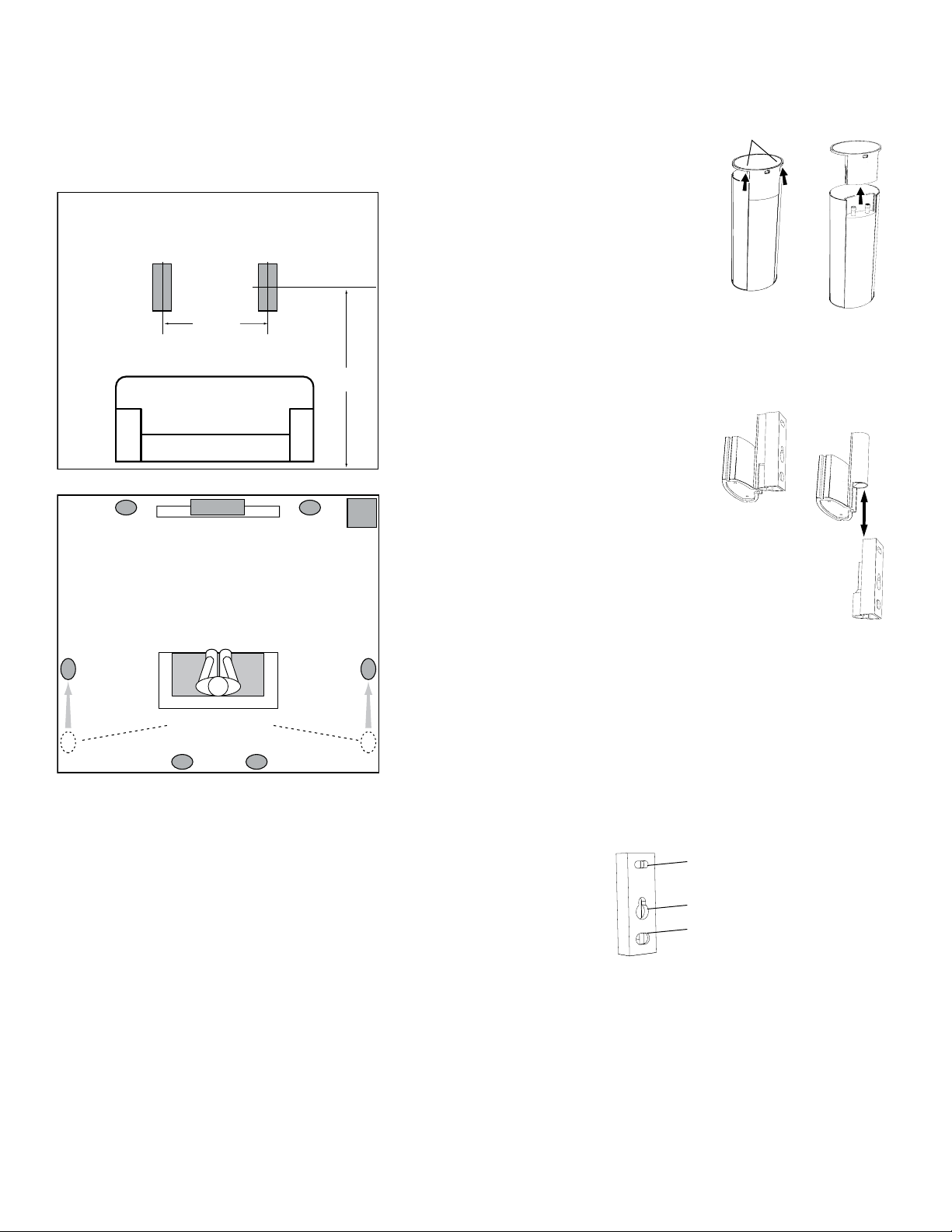
Speaker Placement
Expanding a 5.1-Channel System to a 7.1-Channel
System
The surround back speakers should be placed against the rear wall
directly behind the listeners, 3–6 feet (0.9m–1.8m) apart, 5–6 feet
(1.5m –1.8m) of f the floor.
Mounting Options for
HKTS 30SAT-2 Speakers
Shelf Placement
You can place the HKTS 30SAT-2
speakers on shelves. The satellite
speakers have built-in bases for shelf
placement. You can also remove the
bases if you desire.
Apply pressure evenly
to both sides of base
Lift bas e straight
off speaker
Front Left
Surround Lef t
Speaker
Surround Back
Right Speaker
Speaker
Surround Back
Left Spea ker
(0.9m – 1.8m)
TV
If original surrou nd speakers
are behind listen ers, move them
to a point to directly at
listener s' sides
3 – 6 ft
Center
Speaker
Surround Back
Left Spea ker
Surround Back
Right Speaker
Front Right
Speaker
Surround Right
5 – 6 ft
(1.5m – 1.8m)
Subwoofer
Speaker
NOTE: If your original surround speakers are located behind the
listeners, you should move them up so they are directly to the
listeners’ sides.
To remove a speaker’s base, pull it
straight of f the speaker, as shown in
the illustration. Applying even pressure
to both sides of the base will allow it
to slide off smoothly.
Wall-Mounting
IMPORTANT: Read the Speaker Connections
section, on page 5, before wall-mounting
the HKTS 30S AT-2 speakers. You will need to
insert the speaker wires through the wallmount brackets and connect the wires to
the speakers during the process of
installing the wall-mount brackets.
NOTE: If you are using your own speaker wire,
it must be no thicker than the wire supplied
with the speakers. Thicker wire will prevent
the wall-mount bracket from sliding onto the
speaker.
1. Decide on the location for the speaker
(see Speaker Placement, opposite).
2. Remove the speaker’s base as explained in
Shelf Placement, above.
3. Disassemble the wall-mount bracket by sliding the two
sections apart, as shown in the illustration.
4. Attach the wall portion of the wall-mount bracket onto
the wall using hardware that is appropriate for the wall’s
construction and materials. We recommend first anchor ing the wall-mount bracket using its keyhole, then
attaching it with another anchor through its top opening,
as shown in the illustration. Note that the HKTS 30SAT-2
speakers weigh 3.3 lb (1.5kg ). Be sure to use hardware
that can support this weight.
Pull sections
apart
If You’re Adding to an Existing HKTS 30 Speaker
System:
Your HKTS 30SAT-2 speakers are designed to expand an exist-
ing HKTS 30 speaker system from 5.1 channels to 7.1 channels.
You can connect the HKTS 30SAT-2 speakers to your receiver’s or
amplifier’s surround back left and surround back right outputs.
If You’re Adding to an Existing HKTS 20 Speaker
System:
Your HKTS 30SAT-2 speakers are designed to expand an exist-
ing HKTS20 speaker system from 5.1 channels to 7.1 channels
by replacing the existing front left and front right speakers. You
can then connect your existing HKTS20 front left and front right
speakers to your receiver’s or amplifier’s surround back left and
surround back right outputs.
Top opening
Keyhole opening
Bottom ope ning
3
Page 4

NOTE: If you’re running the speaker wire through the wall, you can
bring it out directly behind the wall-mount bracket’s location and insert
it through the bottom opening in the wall portion of the wall-mount
bracket, as shown in the illustration. Inserting it will keep the wire
completely hidden from view once the installation is complete.
Insert wire into
bottom opening
Bring wire out
through here
5. If you’re not running the speaker wire through the wall, insert
it through the wall portion of the wall-mount bracket, as
shown in the illustration.
6. Pass the speaker wire through the speaker portion of the
wall-mount bracket, as shown in the illustration.
8. Connect the speaker wire to the speaker terminals, as shown in
the illustration:
• Press down on the top of the terminal to open the connection hole.
• Insert the wire’s bare end all the way into the hole.
• Release the terminal to secure the wire.
Insert the conductor with the colored band into the speaker’s
red ( + ) terminal, and insert the other conductor into the speaker’s
black ( – ) terminal.
–
+
Push down on cap
to open hole
Insert bar e wire
into open hole
Release ca p
to secure wire
IMPORTANT: Make sure the ( + ) and ( – ) bare wires do not touch
each other or the other terminal. Touching wires can cause a short
circuit that can damage your receiver or amplifier.
9. Slide the speaker portion of the wall-mount bracket onto the speaker, as
shown in the illustration. Fit the wall-mount bracket’s grooves onto the
rails in the speaker, and apply even pressure on both sides of the wall mount bracket so it slides straight onto the speaker.
• Push the wall-mount bracket all the way onto the speaker until it
snaps into place.
• Pull any slack speaker wire back through the wall-mount bracket
as you slide the wall-mount bracket onto the speaker.
Push down evenly on both sides of wall-mount bracket
Fit bracke t grooves
onto speaker rails
Bring wire in
through here
Bring wire out
through here
7. If you have not already removed the speaker’s base, do so by
pulling it straight of f the speaker, as shown in the illustration.
Applying even pressure to both sides of the base will allow it
to slide off smoothly.
Apply pressure evenly
to both sides of base
CAUTION: Before making speaker connections, be sure
that your receiver or amplifier is turned OFF and,
Lift bas e straight
off speaker
preferably, its AC cord is unplugged from the AC outlet.
10. Slide the speaker onto the wall-mount bracket’s wall section,
as shown in the illustration. Pull any slack speaker wire back
through the wall-mount bracket's wall section.
Slide speaker
onto wall-mount
bracket
11. Fit the metal stop plate into the recess on the bottom of the
wall-mount bracket with the pad facing the bracket, and
fasten it to the bracket using two of the supplied
screws. Fastening it will prevent the speaker from detaching
from the wall-mount bracket and will hold the speaker in
position as you rotate it on the wall-mount bracket.
Stop plate
Supplied scre ws
4
Page 5

Speaker Connections
CAUTION: Before making speaker connections, be sure that your
receiver or amplifier is turned OFF and, preferably, its AC cord is
unplugged from the AC power outlet.
Color-Coding System
The HK TS30 SAT-2 uses the channel color-coding system established
by the Consumer Electronics Association (CEA ) to make setting up
your home theater speaker system as easy as possible. The HKTS 30
systems include speaker wires with colored bands on each end.
Speaker Position Wire Color Band
Surround Back Le ft
Surround Back Ri ght
Speakers and receivers/amplifiers have corresponding ( + ) and ( – )
connection terminals. Most electronics manufacturers, including
Harman Kardon, have been using red to denote the ( + ) terminal and
black for the ( – ) terminal. Newer Harman Kardon receivers conform
to the CEA standard and therefore use a color other than red to
denote the ( + ) terminal for some speaker positions.
Each speaker wire included with your system has colored bands at
both ends of the ( + ) conductor. In addition to the colored bands at
each end, each speaker wire’s ( + ) terminal has ribs molded into its
insulation to help you identif y it, while the (– ) terminal has no ribs.
Bro wn
Tan
Connecting HKTS 30SAT-2 Speakers with the
Supplied Wall-Mount Brackets
Follow the instructions in Wall-Mounting on page 3.
Connecting HKTS 30SAT-2 Speakers with the
Supplied Bases
1. Remove the speaker’s base (see Shelf Placement, on page 3 ).
2. Pass the speaker wire through the opening in the speaker’s
base.
3. Connect the speaker wire as described in Color-Coding System,
opposite.
4. Reat tach the speaker’s base, as shown in the illustration.
It is very important to connect each speaker identically: ( + )
on the speaker to ( + ) on the receiver or amplifier, and ( – ) on
the speaker to ( – ) on the receiver or amplifier. Miswiring one or
more speakers results in thin sound, weak bass and a poor stereo
image. With the advent of multichannel surround-sound systems,
connecting all of the speakers in your system correctly is very important for achieving the proper ambience and directionality of the sound
coming from the speakers.
To connect the speaker wire to the terminals on the speakers, press
down on the top of the terminal to open the connection hole, insert
the wire’s bare end all the way into the hole, and release the terminal
to secure the wire. Inser t the conductor with the colored band into
the speaker’s red ( + ) terminal, and insert the other conductor into
the speaker’s black ( – ) terminal, as shown in the illustration.
–
+
Push down on cap
to open hole
Insert bar e wire
into open hole
Release ca p
to secure wire
IMPORTANT: Make sure the ( + ) and ( – ) bare wires do not
touch each other or the other terminal. Touching wires can
cause a short circuit that can damage your receiver or
amplifier.
5
Page 6

Receiver
RIGHT
LEFT
Surround
Back
+ –
+ –
Surround Back Left
Speaker Cable
(Brown Bands)
+–
Surround Back
Left
Surround Back Right
Speaker Cable
(Tan Bands)
+–
Surround Back
Right
6
Page 7

Troubleshooting
If ther e is no s ound from any of the speaker s:
• Check that the receiver/amplifier is on and a disc or other source is playing.
• Make sure t hat all wires and connections between the recei ver/ amplifier
and the speakers are connec ted properly.
• Make sure t hat none of the speaker wires is frayed, cut or punctured.
• Review the prop er operation of your r eceiver/ amplifier.
If ther e is no s ound coming from one speaker:
• Check that the balance control on your re ceiver/amplifier is not se t all the
way to one channel.
• Check your receiver/amplifier’s speaker setup procedure to make sure that
the speaker in question has been enabled and its volume level has not been
turned all the way down.
• Make sure t hat all wires and connections between the recei ver/ amplifier
and the speaker are connected properly.
• Make sure t hat none of the speaker wires is frayed, cut or punctured.
If ther e is no s ound coming from the surround sp eakers :
• Check your receiver/amplifier’s speaker setup procedure to make sure that
the surround speakers have been enabled and their volume levels have not
been turned all the way down.
• Make sure t hat all wires and connections between the recei ver/ amplifier
and the surround speakers are connected properly.
• Make sure t hat none of the speaker wires is frayed, cut or punctured.
• Review proper opera tion of your receiver/amplifier and its surround-
sound features.
• Make sure t hat the movie or T V show you’r e watching has been recorded in a
surro und- soun d mode. I f it has not, check to see if yo ur receiver/ampli fier
has a different surround-sound mode that you can use.
• Review the oper ation of your DVD player and th e DV D jacket to make sure the
D VD features the Dolby
have selected that mode using both the DV D player’s menu and the disc’s
menu.
®
Digital or DTS® surround-sound mode and that you
If the syst em plays at low volumes but shuts off as volume is increased :
• Make sure t hat all wires and connections between the recei ver/ amplifier
and the speakers are connected properly.
• Make sure t hat none of the speaker wires is frayed, cut or punctured.
• If you’re using more than one pair of main speakers, check to be sure that
you’re not oper ating the sys tem below the receiver /amplifier’s minimum
impedance requirements. If you're not sure sure how to check the
impedance, ask your audio retailer.
7
Page 8

Specifications
HKTS 30SAT-2 Satellites
Recommended Power
10 ~ 120 watts
Impedance
8 ohms nominal
Sensitivity
86dB @ 2.83V/1 meter
Tweeter
One 3/4" (19mm) dome, video-shielded
Midrange
Dual 3" (75mm) drivers, video-shielded
Dimensions – including stands (H x W x D)
11-25/ 32" x 4-11/32" x 3-15/32"
(299mm x 110mm x 88mm)
Weight
3.3 lb (1.5kg)
© 2010 Ha rman International In dust ries , Incorp orat ed. All r ight s reserv ed.
Fea ture s, specifications and appe arance are su bjec t to chang e without not ice.
Har man Kard on is a tr ademark o f Harman Inte rnat iona l Industries, Inc orporated, r egis tered in t he United States
and /or o ther coun trie s. Designed to Ent ert ain i s a t rademark of Harman Int erna tion al Industries, In corpora ted.
CE A is a reg iste red trademark of t he C onsumer Elect roni cs A ssociati on. Dolby is a register ed tr adem ark of Do lby L aborato ries .
DTS is a regi ster ed trademark of DT S, Inc .
Harman Consumer, Inc.
8500 Balboa Bouleva rd, Northridge, CA 91329 USA
516.255.45 45 (USA only)
www.harman kardon.com
Made in P.R.C.
Part # 950-02 89-001
8
 Loading...