

Page 1
CONTENTS
HKTS 20+30 USER GUIDE 2
HKTS 20+30WQ CENTER EXPL VIEW 40
harman/kardon Service Manual
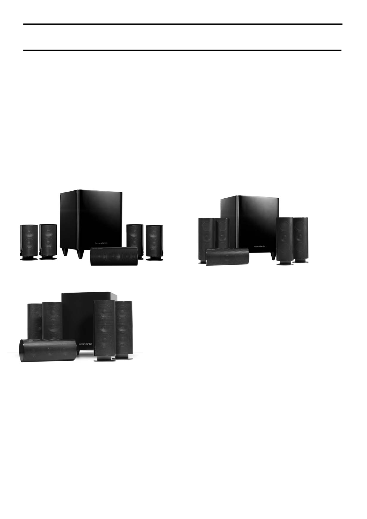
HKTS 20/230,
HKTS 30/230 – HKTS 30/WQ
HKTS 60/230.
Surround loudspeaker systems wit h active subwoofer.
Earlier version s with HKTS 200 SUB.
Later versions with HKTS 210 SUB.
HKTS 60 with 200 SUB USER GUIDE 13
HKTS 60 with 210 SUB USER GUIDE 24
HKTS 20 SAT EXPLODED VIEW/PARTS 36
HKTS 30 SAT EXPLODED VIEW/PARTS 37
HKTS 30WQ SAT EXPLODED VIEW 38
HKTS 20+30 CENTER EXPLODED VIEW 39
Released EU2011 Harman Consumer Group, Inc. Rev 2, 11/2011
8500 Balboa Boulevard
Northridge, California 91329
HKTS 200 SUB EXPLODED VIEW/PARTS 41
HKTS 200 PART S LIST 42
HKTS 200 SCHEMATIC DIAGRAM 43
HKTS 210 SUB EXPLODED VIEW/PARTS 44
HKTS 210 PART S LIST 45
HKTS 210 SCHEMATIC DIAGRAMS 46
Page 2

User Guide
harman/kardon
HKTS 20/30/60 -230V Service Manual
Page 2 of 48
English
HKTS 20/HKTS 30
Home Theater Speaker System
Designed to Entertain.
™
Page 3
Harman Kardon®
harman/kardon
HKTS 20/30/60 -230V Service Manual
Page 3 of 48
HKTS 20 / HKTS 30
Introduction
Thank you for purchasing the Harman Kardon® HKTS20/HKTS30 speaker system, with
which you’re about to begin many years of listening enjoyment. The HKTS20/HKTS30 has
been custom designed to provide all the excitement and power of the cinema experience
in your own living room.
While sophisticated electronics and state-of-the-art speaker components are hard at work
within the HKTS20 and HKTS30, hookup and operation are simple. Color-keyed cables and
connections, and simple controls make the HKTS20/HKTS30 easy to use.
To obtain maximum enjoyment from your new home theater speaker system, we urge
you to take a few minutes to read through this manual. This will help ensure that the
connections you make to your receiver (or preamp/processor), amplifier and other devices
are correct. In addition, a few minutes spent learning the functions of the various controls
will enable you to take advantage of all the power and refinement the HKTS20/HKTS30 is
able to deliver.
If you have any questions about this product, its installation or its operation, please
contact your dealer, the best local source of information.
Description and Features
The HKTS20/HKTS30 is a complete six-piece home theater speaker system that includes:
An 8-inch, 200-watt powered subwoofer
•
Four identical two-way video-shielded satellite speakers (the HKTS30 satellite
•
speakers feature dual drivers) for the left and right front, and left and right rear
(surround) speaker positions
•
A dedicated, voice-matched, video-shielded, dual-driver center speaker
Removable bases and wall-mount brackets for the satellite speakers and a wall-
•
mount bracket for the center speaker
All of the cables you need to connect all of the speakers to your receiver or preamp/
•
processor and amplifier.
The speaker cables all use a color-coding system to conform to the Consumer Electronics
Association (CEA) standard. This color-coding system minimizes confusion when
connecting the speakers, especially when you are connecting them to a Harman Kardon
receiver.
The HKTS200SUB subwoofer is equipped with a special LFE input that simplifies
connection to receivers and preamp/processors with dedicated subwoofer outputs that
carry low-frequency signals. Other conveniences include a level control, a phase switch for
fine-tuning bass response to suit your listening environment and taste, and an efficient
switching system that senses the presence of an audio signal and automatically switches
the subwoofer from standby mode to on.
Wall-mount brackets are included for the satellite and center speakers, and shelf stands
are included for the satellite speakers. Optional HKFS3 floorstands are available separately
from your Harman Kardon dealer. Harman Kardon invented the high-fidelity receiver fifty
years ago. With state-of-the-art features and time-honored circuit designs, the HKTS20/
HKTS30 is a perfect complement to a Harman Kardon receiver, or any home theater
system.
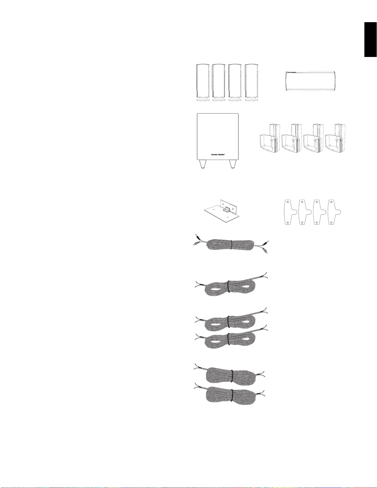
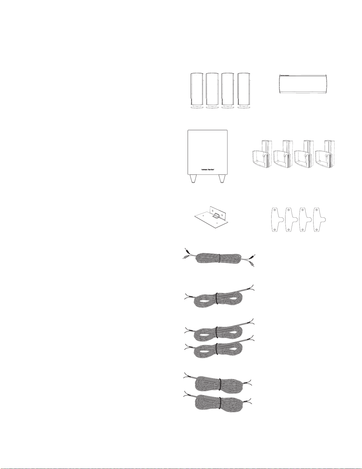
Included
Four satellite speakers for front left/right and surround left/right
(HKTS30 satellites shown)
One powered subwoofer
One wall-mount bracket for
center speaker
Four wall-mount brackets for satellite
speakers
Four metal stop plates and screws
(for satellite speaker wall-mount brackets)
One combination LFE and trigger cable for
connection to the subwoofer
(LFE cable has purple connectors)
One 4-meter (13.1-foot) speaker cable for
center speaker (green color bands)
Two 5-meter (16.4-foot) speaker cables for
front satellites (red and white color bands)
ENGLISH
Two 10-meter (32.8-foot) speaker cables for
rear satellites
(gray and blue color bands)
Page 4
PL0004-01001
1
2
3
4
5
8
9
6
7
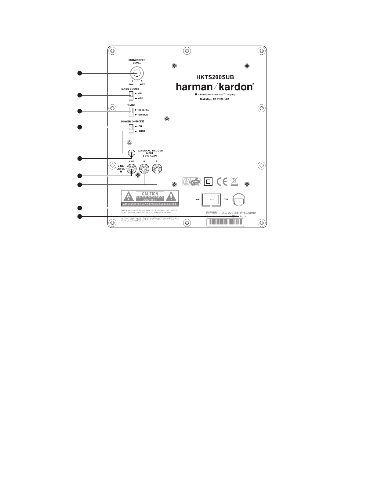
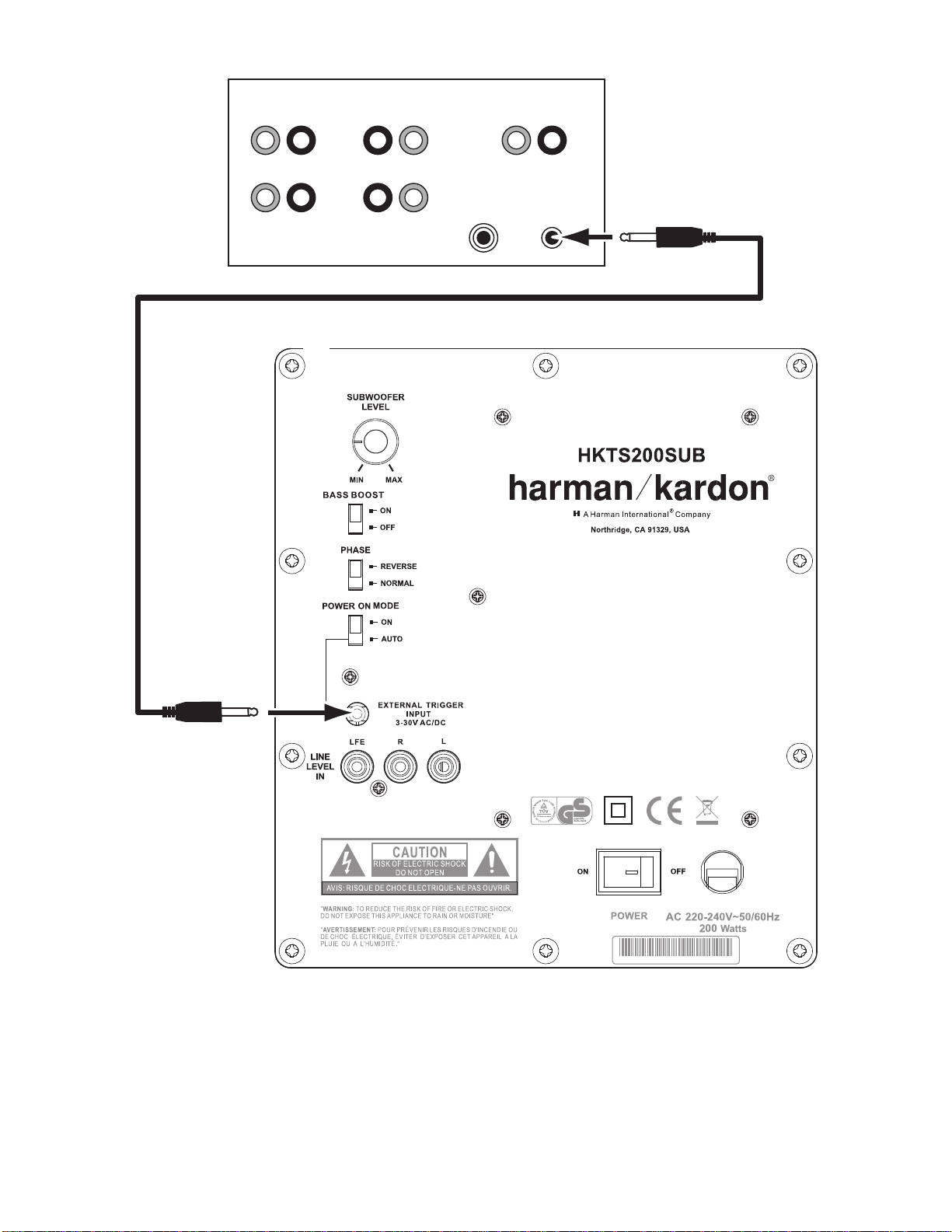
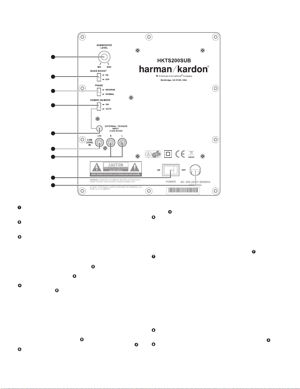
HKTS200SUB Rear-Panel Connections
harman/kardon
HKTS 20/30/60 -230V Service Manual
Page 4 of 48
.
Subwoofer Level Control:
Use this control to adjust the HKTS200SUB’s volume. Turn
clockwise to increase the volume; turn counterclockwise to decrease the volume.
1.
Bass Boost Switch:
Set this switch to ON to enhance the HKTS200SUB’s low-frequency
performance. Set this switch to OFF for normal low-frequency performance.
2.
Phase Switch:
The Phase Switch 2 determines whether the HKTS200SUB’s piston-like
action moves in and out in phase with the satellite speakers. If the subwoofer were
to play out of phase with the satellite speakers, the sound waves produced by the
subwoofer could be canceled out, reducing bass performance and sonic impact. This
phenomenon depends in part on the relative placement of all the speakers in the
room. In most cases the Phase Switch
2
should be left in the NORMAL position.
However, it does no harm to experiment, and you can leave the Phase Switch
the position that maximizes bass response and impact.
3.
Power On Mode Switch:
7
is set to ON, the HKTS200SUB will automatically turn itself on when it receives an
audio signal, and will enter the standby mode once no audio signal has been received
for about 15 minutes. When this switch is set in the ON position, the HKTS200SUB
When set in the AUTO position and when the Power Switch
will remain on whether or not it is receiving an audio signal.
An LED on the HKTS200SUB’s top panel indicates whether the subwoofer is in the on
or standby state:
• When the LED is illuminated white, the HKTS200SUB is turned on.
• When the LED is not illuminated, the HKTS200SUB is in standby mode.
7
When the Master Power Switch
illuminated, no matter what setting the Power On Mode Switch
4.
External Trigger Input:
cable to connect the External Trigger Input to the trigger output of another
compatible component. Whenever a trigger signal between 3 and 30V (AC or DC) is
detected, the HKTS200SUB’s amplifier will turn on. The HKTS200SUB’s amplifier will
Use the mini-plug of the supplied combination LFE and trigger
is set to OFF, the LED will not be
3
is in.
turn off after the trigger signal ceases. (This will occur even when the Power On
3
Mode Switch
is in the AUTO position.)
5.
Line-Level LFE In Connector:
Use the LFE (purple) connector of the supplied combination
LFE and trigger cable to connect the Line-Level LFE In to the dedicated subwoofer
output of a receiver or preamp/processor. This input bypasses the HKTS200SUB’s
internal crossover circuitry, so it should only be used with a subwoofer output that has
been low-pass filtered. If your receiver or preamp/processor does not have a dedicated
subwoofer output that is low-pass filtered you should use the HKTS200SUB’s Line-
6
Level L/R In Connectors
6.
Line-Level L/R In Connectors:
instead.
Use these connectors if your receiver or preamp/processor
does not have digital surround sound decoding or a subwoofer output that is low-pass
filtered.
2
in
• If your receiver or preamp/processor has a separate subwoofer output, use the LFE
(purple) connec tor of the supplied combination LFE and trigger cable to connect it to
either one of the HKTS200SUB’s Line-Level L/R In Connectors.
• If your receiver or preamp/processor does not have a separate subwoofer output,
use two Y-adapters (not supplied). Connect an adapter’s single end to the unit’s
preamp output for that channel. Connect one of the adapter’s dual ends to the main
amp input for that channel, and connect the adapter’s other dual end to one of the
HKTS200SUB’s Line-Level L/R In Connectors. Repeat with the other Y-adapter,
preamp channel, main amp input and HKTS200SUB Line-Level L/R In Connector.
7.
Power Switch:
Set this switch in the ON position to turn the HKTS200SUB on. The
subwoofer will then either be on or in standby mode, depending on the setting of the
3
Power On Mode Switch
8.
Power Cord (Non-Detachable):
.
After you have made and verified all subwoofer
and speaker connections described in this manual, plug this cord into an active,
unswitched electrical outlet for proper operation of the HKTS200SUB. DO NOT plug this
cord into the accessory outlets found in some audio components.
4
Page 5
Speaker Placement
0 – 2ft
harman/kardon
HKTS 20/30/60 -230V Service Manual
Page 5 of 48
NOTE: The following speaker placement, mounting and connection instructions are
identical for the HKTS20 and HKTS30 systems.
Color-Coding System
The HKTS20 and HKTS30 use the channel color-coding system established by the CEA
to make setting up your home theater speaker system as easy as possible. The HKTS20/
HKTS30 systems include speaker wires with color bands on each end.
Speaker Position Wire Color Band
Front Left White
Front Right Red
Center Green
Surround Left Blue
Surround Right Gray
Subwoofer Purple
Placing the Front Speakers
The front speakers should be placed the same
Left Front
Speaker
Right Front
Placing the Center Speaker
Center
Speaker
Left Front
Speaker
Right Front
Speaker
Placing the Subwoofer
Left Front
Speaker
Right Front
Speaker
Subwoofer
distance from each other as they are from the
Speaker
listening position. They should be placed at about
the same height from the floor as the listener’s
ears will be. They also can be angled toward the
listener.
The center speaker should be placed slightly
behind (farther away from the listener) the front
left and right speakers. Its center should be no
0 - 2 ft
more than 2 feet (61cm) above or below the
(0 - 61cm)
tweeters of the front left and right speakers. If you
have a CRT television, it may be convenient to set
the center speaker on top of the television set.
Since our ears do not hear directional sound
at the low frequencies where the subwoofer
operates, it will have good performance from
just about any location in your room. However,
the best bass reproduction is likely to be heard
when the subwoofer is placed in a corner along
the same wall as the front left and right speakers.
You can experiment with subwoofer placment
by temporarily placing it in the listening position
and playing music with strong bass content. Move
around to various locations in the room while
the system is playing and listen until you find the
location where the bass performance is best. Place
the subwoofer in that location.
The two surround speakers should be placed slightly behind the listening position, facing
each other and, ideally, should be 5–6 feet (1.5m–1.8m) from the floor. An alternate
location would be on a wall behind the listening position, facing forward. The surround
speakers should not call attention to themselves while they’re playing.
Experiment with their placement until you hear a diffuse, ambient sound accompanying
the program material heard from the front left and right and center speakers.
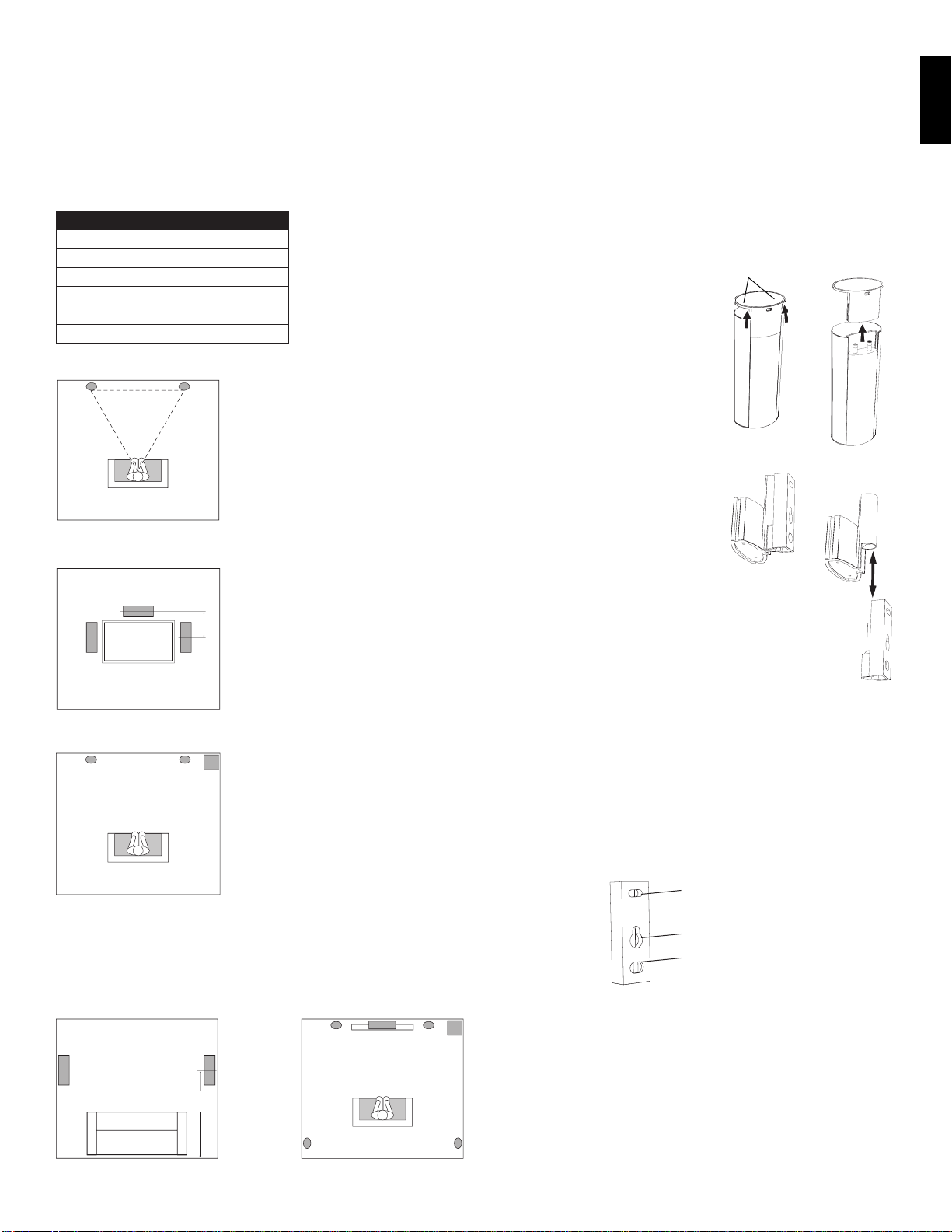
Mounting Options for Satellite and Center
Speakers
Shelf Placement
You can place the satellite and center speakers
Apply Pressure Evenly
to Both Sides of Base
on shelves. The satellite speakers have built-in
bases for shelf placement. You can also remove
the bases if desired.
To remove a satellite speaker’s base, pull
it straight off the speaker, as shown in the
illustration. Applying even pressure to both sides
of the base will allow it to slide off smoothly.
Wall-Mounting: Satellite Speakers
IMPORTANT: Read the Speaker Connec tions
section, on page 7, before wall-mounting the
satellite speakers. You will need to insert the
speaker wires through the wall mounts and
connect the wires to the speakers during the
process of installing the wall-mounts.
NOTE: If you are using your own speaker wire, it must
be no thicker than the wire supplied with the speakers. Thicker
wire will prevent the wall-mount bracket from sliding onto the
speaker.
Decide on the location for the speaker 1.
(see Speaker Placement, opposite).
Remove the speaker’s base as explained in 2. Shelf Placement, above.
Disassemble the wall-mount bracket by sliding the two sections apart, as shown in the 3.
illustration.
Attach the wall portion of the wall-mount onto the wall using hardware that is 4.
appropriate for the wall’s construction and materials. We recommend first anchoring
the mount using its keyhole, then attaching it with another anchor through its top
opening, as shown in the illustration. Note that the satellite speakers weigh 3.3 lb
(1.5kg). Be sure to use hardware that can support this weight.
Top Opening
Keyhole Opening
Bottom Opening
Lift Base Straight
off Speaker
Pull Sections
Apart
ENG LIS H
Placing the Surround Speakers
Left Surround
Sound
Right Surround
Sound
(1.5m - 1.8m)
5 - 6 ft
Left Front
Speaker
Left Surround
Sound
Center
Speaker
Right Front
Speaker
Subwoofer
Right Surround
Sound
Page 6
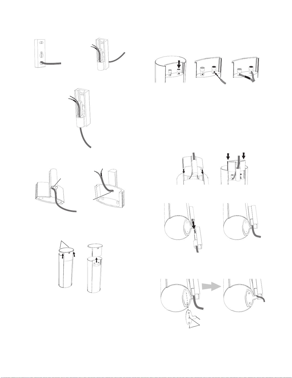
NOTE: If you’re running the speaker wire through the wall you can bring it out directly
+
–
harman/kardon
HKTS 20/30/60 -230V Service Manual
Page 6 of 48
behind the bracket location and insert it through the bottom opening in the wall portion
of the wall-mount, as shown in the illustration. This will keep the wire completely hidden
from view once the installation is complete.
Insert Wire into
Bottom Opening
Bring Wire Out
through Here
If you’re not running the speaker wire through the wall, insert it through the wall portion
5.
of the wall-mount bracket as shown in the illustration.
Pass the speaker wire through the speaker portion of the wall-mount as shown in the 6.
illustration.
Connect the speaker wire to the speaker terminals as shown in the illustration: 8.
Press down on the top of the terminal to open the connection hole.a)
Insert the wire’s bare end all the way into the hole.b)
Release the terminal to secure the wire. c)
Insert the conductor with the colored band into the speaker’s red ( + ) terminal, and
insert the other conductor into the speaker’s black ( – ) terminal.
A. Push Down on Cap to
Open Hole
B. Insert Bare Wire into
Open Hole
C. Release Cap to Secure Wire
IMPORTANT: Make sure the ( + ) and ( – ) bare wires do not touch each other or the
other terminal. Touching wires can cause a short circuit that can damage your receiver
or amplifier.
Slide the speaker portion of wall-mount onto the speaker as shown in the illustration. Fit
9.
the grooves on the mount onto the rails in the speaker, and apply even pressure on
both sides of the mount so it slides straight onto the speaker.
• Push the mount all the way onto the speaker until it snaps into place.
• Pull any slack speaker wire back through the mount as you slide the mount onto the
speaker.
Push Down Evenly on Both Sides of Bracket
Fit Bracket Grooves
onto Speaker Rails
Bring Wire In
through Here
Bring Wire Out
through Here
If you have not already removed the speaker’s base, do so by pulling it straight off the 7.
speaker, as shown in the illustration. Applying even pressure to both sides of the base
will allow it to slide off smoothly.
Apply Pressure Evenly
to Both Sides of Base
Lift Base Straight
off Speaker
CAUTION: Before making speaker connections, be sure that your receiver or amplifier
is turned OFF and preferably, its AC cord is unplugged from the AC outlet.
Slide the speaker onto the mount’s wall section as shown in the illustration. Pull any slack
10.
speaker wire back through the mount’s wall section.
Slide Speaker
onto Wall-Mount
Fit the metal stop plate into the recess on the bottom of the mount with the pad facing 11.
the mount, and fasten it to the mount using two of the supplied screws. This will
prevent The speaker from detaching from the bracket and will hold the speaker’s
position as you rotate it on the mount.
Stop Plate
Supplied Screws
6
Page 7
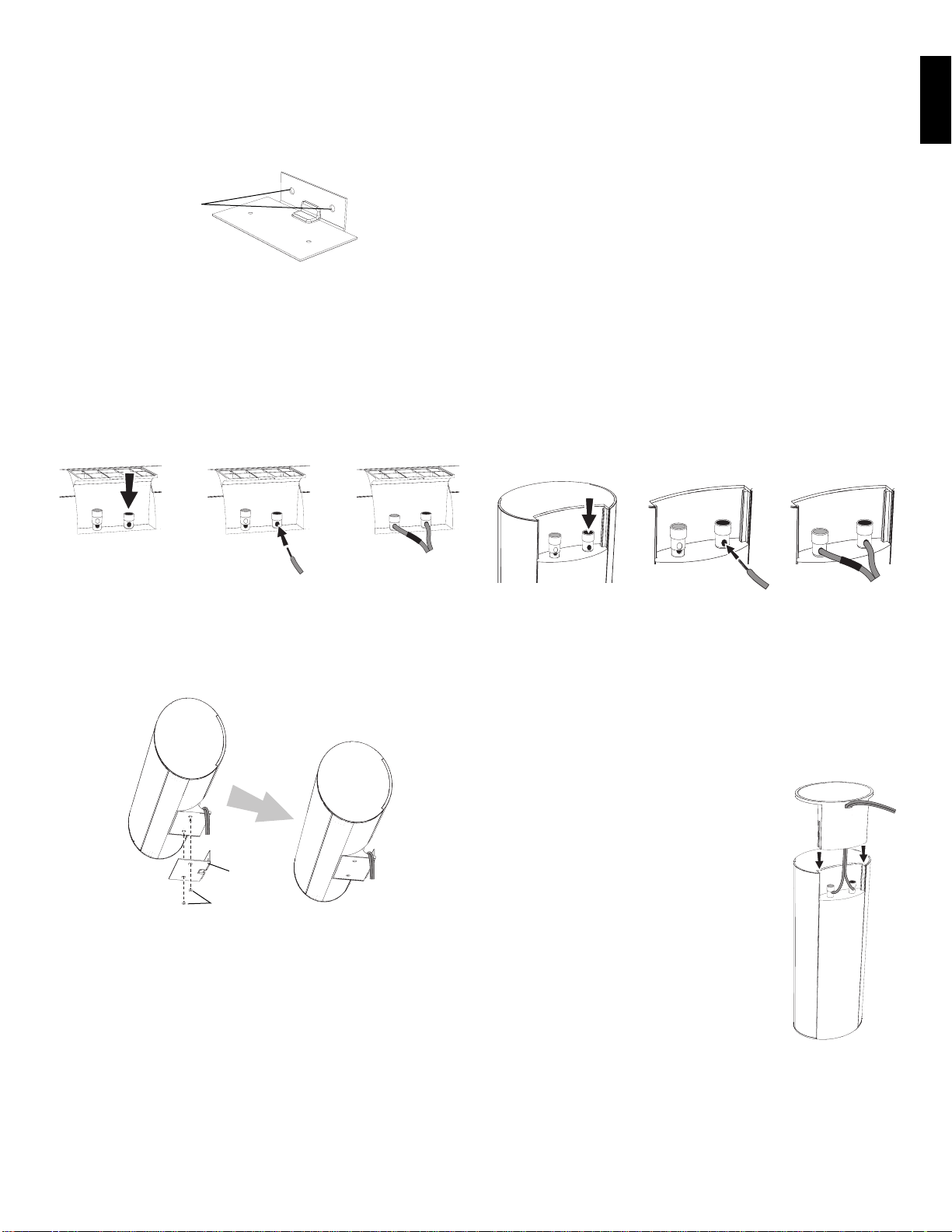
Wall-Mounting: Center Speaker
+
–
+
–
harman/kardon
HKTS 20/30/60 -230V Service Manual
Page 7 of 48
Decide on the location for the speaker (see 1. Speaker Placement, on page 5).
Attach the center speaker wall-mount bracket to the wall using hardware that is 2.
appropriate for the wall’s construction and materials. Attach the anchors through the
holes shown in the illustration.
Use These Holes
to Attach Bracket
to Wall
NOTE: The center speaker weighs 3.2 lb (1.45kg). Be sure to use hardware that can
support this weight.
CAUTION: Before making speaker connections, be sure that your receiver or amplifier is
turned OFF and preferably, its AC cord is unplugged from the AC power source.
Connect the speaker wire to the speaker terminals. Press down on the top of the terminal
3.
to open the connection hole, insert the wire’s bare end all the way into the hole and
release the terminal to secure the wire. Insert the conductor with the colored band
into the speaker’s red ( + ) terminal, and insert the other conductor into the speaker’s
black ( – ) terminal, as shown in the illustration.
A. Push Down on Cap to
Open Hole
B. Insert Bare Wire into
Open Hole
C. Release Cap to Secure Wire
Speakers and receivers/amplifiers have corresponding ( + ) and ( – ) connection
terminals. Most electronics manufacturers, including Harman Kardon, use red to denote
the ( + ) terminal and black for the ( – ) terminal. Newer Harman Kardon receivers
conform to the CEA standard and therefore use a color other than red to denote the ( + )
terminal for some speaker positions. See the table in Color-Coding System, on page 5.
Each speaker wire included with your system has colored bands at both ends of the ( + )
conductor, and the subwoofer cable has purple connectors that correspond to the color of
the HKTS200SUB’s LFE jack. This system helps ensure that the speaker in each location is
connected to the correct receiver or amplifier terminals. In addition to the colored bands
at each end, each speaker wire’s ( + ) terminal has ribs molded into its insulation to help
identify it.
It is very important to connect each speaker identically: ( + ) on the speaker to ( + ) on
the receiver or amplifier, and ( – ) on the speaker to ( – ) on the receiver or amplifier.
Miswiring one or more speakers results in thin sound, weak ba ss and a poor stereo
image. With the advent of multichannel surround-sound systems, connecting all of the
speakers in your system correctly is very important to achieving the proper ambience and
directionality of the program material.
To connect the speaker wire to the terminals on the satellite and center speakers, press
down on the top of the terminal to open the connection hole, insert the wire’s bare end
all the way into the hole and release the terminal to secure the wire. Insert the conductor
with the colored band into the speaker’s re d ( + ) terminal, and insert the other conductor
into the speaker’s black ( – ) terminal, as shown in the illustration.
ENGLISH
IMPORTANT: Make sure the ( + ) and ( – ) bare wires do not touch each other or the
other terminal. Touching wires can cause a short circuit that can damage your receiv
er or amplifier.
Using two of the supplied screws, attach the center speaker to the wall-mount 4.
bracket, as shown in the illustration.
Wall-Mount
Bracket
Supplied Screws
Speaker Connections
CAUTION: Before making speaker connections, be sure that your receiver or amplifier is
turned OFF and preferably, its AC cord is unplugged from the AC power outlet.
A. Push Down on Cap to
Open Hole
B. Insert Bare Wire into
Open Hole
C. Release Cap to Secure Wire
IMPORTANT: Make sure the ( + ) and ( – ) bare wires do not touch each other or the
other terminal. Touching wires can cause a short circuit that can damage your receiver or
amplifier.
Connecting Satellite Speakers With Supplied
Wall-Mount Brackets
Follow the instructions in Wall-Mounting: Satellite Speakers, on page 5, and
Wall-Mounting: Center Speaker, opposite.
Connecting Satellite Speakers with Supplied Bases
Remove the speaker’s base (see1. Shelf Placement, on page 5).
Pass the speaker wire through the opening in the speaker base.2.
Connect the speaker wire as described above.3.
Reattach the speaker’s base as shown in the illustration.4.
Page 8
PL0004-01001
+–
+– +–
+–+–
LEFT
SUB
LFE OUT
+ – + –
+ –
+ –
+ –
+ –
+ –
RIGHT
SURROUNDFRONT CENTER
Left Front
harman/kardon
HKTS 20/30/60 -230V Service Manual
Page 8 of 48
Center Right Front
Front Left
Speaker Cable
(White Bands)
Receiver
Surround Left
Speaker Cable
(Blue Bands)
Center
Speaker Cable
(Green Bands)
LFE/Trigger Cable
(Purple Ends)
Front Right
Speaker Cable
(Red Bands)
Subwoofer
Surround Right
Speaker Cable
(Gray Bands)
Left
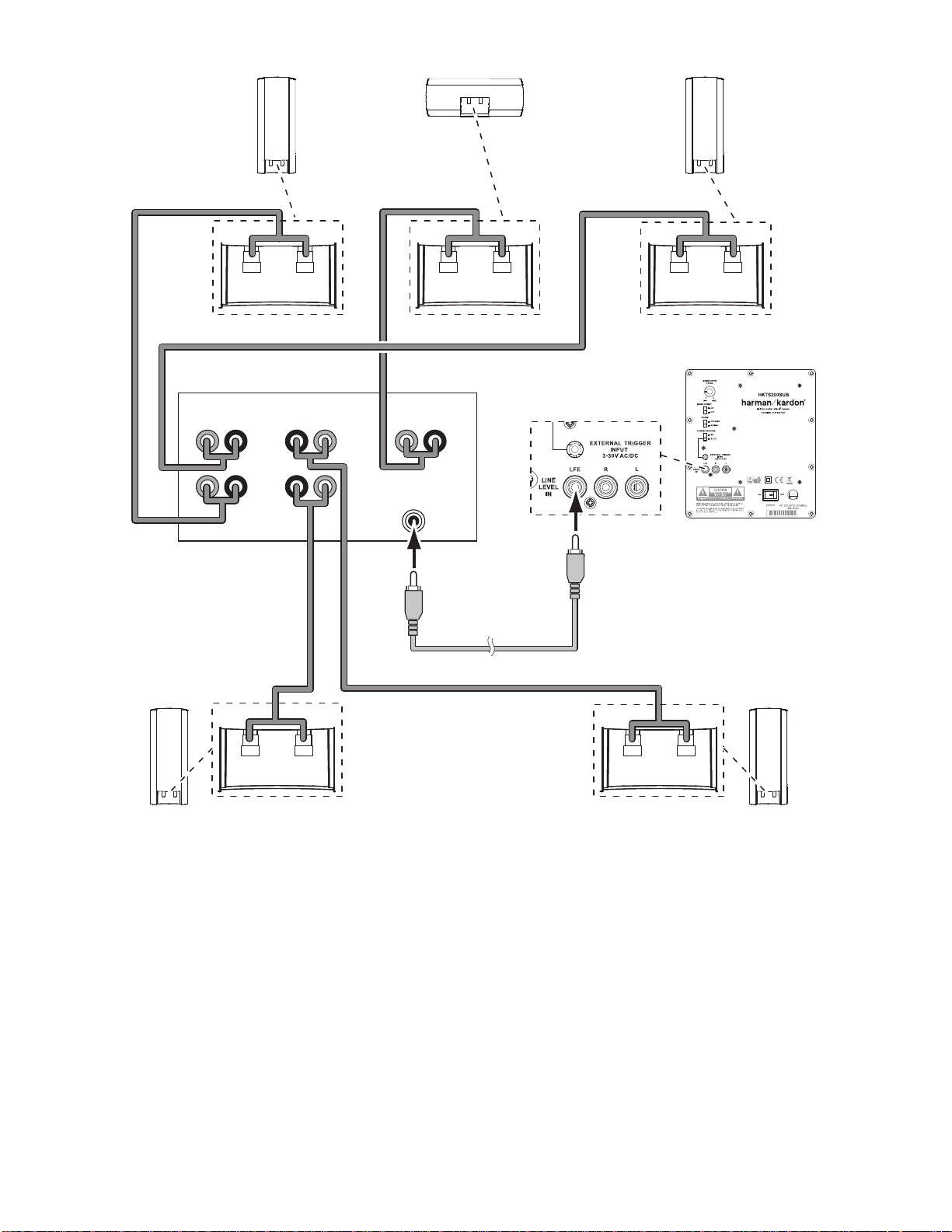
Connecting the Subwoofer to a Receiver or Preamp/Processor With a Dedicated Subwoofer Output
Use this installation method for receivers and preamp/processors that have a dedicated
subwoofer output with low-pass filtering (also called bass management). If the dedicated
subwoofer output does not have low-pass filtering, follow the instructions in Connecting
the Subwoofer to a Receiver or Preamp/Processor With Line Outputs, on page 9.
Use the LFE (purple ) connector of the supplied comb ination LFE and trigger cable to
connect the HKTS200SUB’s Line-Level LFE In Jack
(or LFE output) of your receiver or preamp/processor.
Surround
5
to the dedicated subwoofer output
Connect each satellite speaker and the center speaker to the corresponding speaker
terminals on your receiver or amplifier.
In your receiver or preamp/processor’s setup menu, configure it for Subwoofer ON, and
set the front left, front right, center, and surround speakers to Small. After you have made
and verified all connections, plug the HKTS200SUB’s AC Power Cord
outlet.
Right
Surround
8
into an active AC
8
Page 9
PL0004-01001
+–
+– +–
+–+–
LEFT
LINE-LEVEL
OUTPUTS
L R
+ – + –
+ –
+ –
+ –
+ –
+ –
RIGHT
SURROUNDFRONT CENTER
Left Front
harman/kardon
HKTS 20/30/60 -230V Service Manual
Page 9 of 48
Center Right Front
ENGLISH
Front Left
Speaker Cable
(White Bands)
Receiver
Surround Left
Speaker Cable
(Blue Bands)
Center
Speaker Cable
(Green Bands)
Front Right
Speaker Cable
(Red Bands)
RCA Cable
(Not Supplied)
(Red and White Ends)
Subwoofer
Surround Right
Speaker Cable
(Gray Bands)
Left
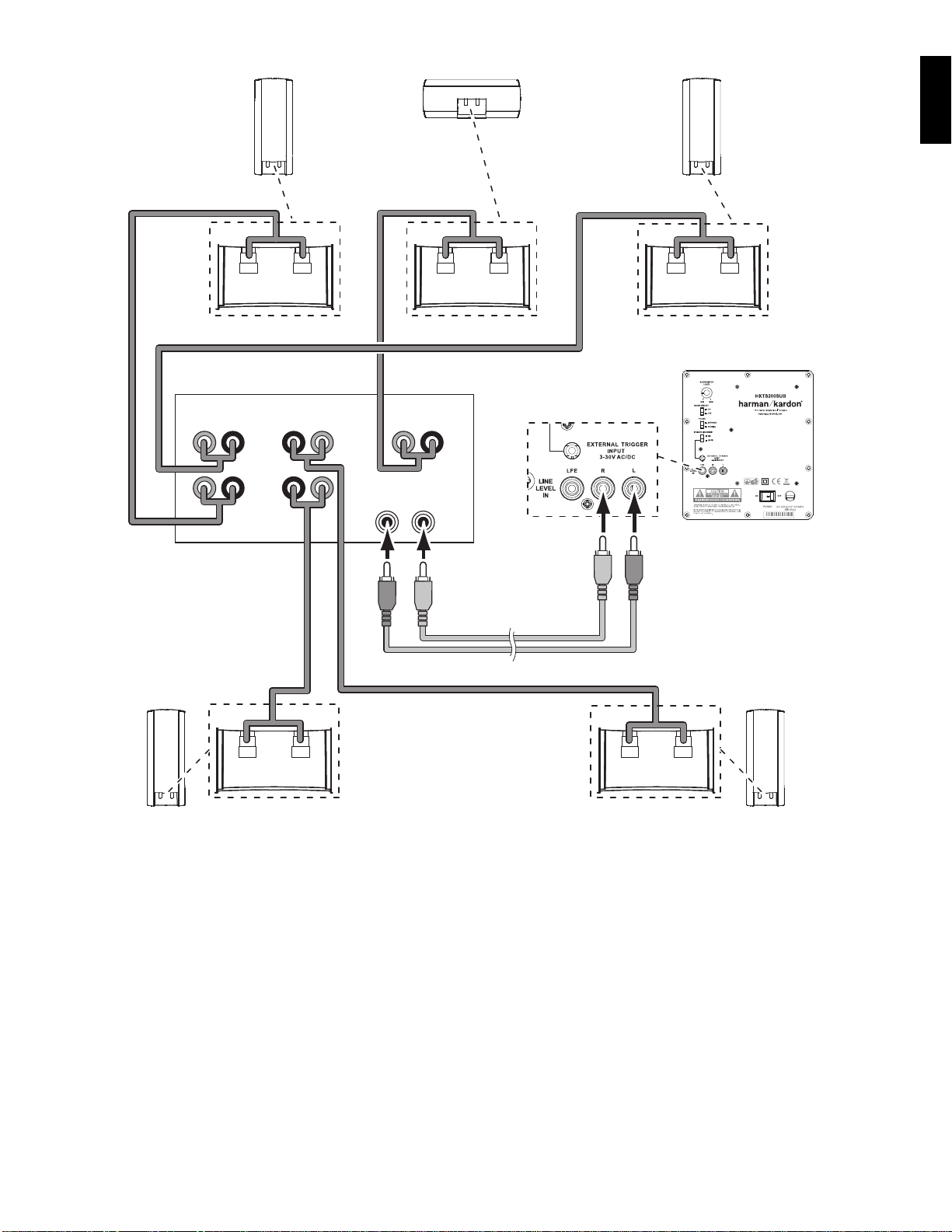
Connecting the Subwoofer to a Receiver or Preamp/Processor With Line Outputs
Surround
Use this installation method for receivers and preamp/processors that do not have a
dedicated subwoofer output, but do have preamp-level (volume-controlled) line outputs.
If the receiver or preamp/processor has a dedicated subwoofer output with low-pass
filtering, see Connecting the Subwoofer to a Receiver or Preamp/Processor With a D edicated
Subwoofer Output, on page 8.
If you’re connec ting to a receiver with left and right line outputs that are not connected to
amplifier inputs, connect the LFE (purple) connector of the supplied combination LFE and
trigger cable to one of those outputs and to either of the HKTS200SUB’s Line -Level L/R
6
In Connectors
. Use a second RCA cable (not supplied) to connect the other receiver or
preamp line output to the other of the HKTS200SUB’s Line -Level L/R In Connectors
If you’re connec ting to a receiver or preamp/processor with left and right line outputs
that are connected to amplifier front left and right inputs, connect the single ends of
Y-adapters (not supplied) to the receiver’s or processor’s left and right line outputs.
Connect one of the Y-adapter’s double ends to the HKTS200SUB’s Line-Level L/R In
6
Connectors
, and connect the other double end to your amplifier’s front left and right
inputs.
Connect each satellite speaker and the center speaker to the corresponding speaker
terminals on your receiver or amplifier.
6
In your receiver or preamp/processor’s setup menu, configure it for Subwoofer ON, and set
.
the front left, front right, center, and surround speakers to Small.
After you have made and verified all connections, plug the HKTS200SUB’s AC Power Cord
8
into an active AC outlet.
Right
Surround
Page 10
PL0004-01001
LEFT
LFE SUB
OUTPUT
12V
TRIGGER
OUTPUT
+ – + –
+ –
+ –
+ –
+ –
+ –
RIGHT
SURROUNDFRONT CENTER
Receiver
harman/kardon
HKTS 20/30/60 -230V Service Manual
Page 10 of 48
Subwoofer
Trigger Cable
(Black Ends)
Connecting to a Trigger Voltage Source
If your preamp/processor or another audio/video component has a trigger voltage
connection that supplies between 3 and 30V (AC or DC), connect it to the HKTS200SUB’s
External Trigger Input Connector
a 3.5mm mini jack you can use the supplied combination LFE/trigger cable to make the
connection.
4
. If the component’s trigger voltage connection has
10
Page 11

TroubleshootingOperation
harman/kardon
HKTS 20/30/60 -230V Service Manual
Page 11 of 48
Turning the Subwoofer On and Off
Set the HKTS200SUB’s Power Switch 7 to the ON position.
If the
•
Power On Mode Switch 3 is set to AUTO, the HKTS200SUB will
automatically turn i tself on when it receives an audio sig nal, and it will go into
standby mode when it has received no audio signal for 15 minutes. The HKTS200
SUB’s LED will illuminate white when the subwoofer is on, and will not be illuminated
when the subwoofer is in standby.
•
Power On Mode Switch 3 is set to ON, the HKTS200SUB will remain on at all
If the
times. The HKTS200 SUB’s LED will illuminate white.
•
External Trigger Input Connector 4 is connected to a trigger voltage source,
If the
the HKTS200SUB will turn on whenever a trigger voltage is present, and will turn off
after the trigger voltage ceases, regardless of the position of the Power On Mode
3
Switch
If you will be away from home for an extended period of time, or if you will not be
using the subwoofer for an extended period, switch the Power Switch
Position.
.
7
to the OFF
Subwoofer Adjustments: Volume
Use the Subwoofer Level Control to set the HKTS200SUB’s volume. Turn the knob
clockwise to increase the subwoofer’s volume; turn the knob counterclockwise to decrease
the subwoofer’s volume.
Subwoofer Adjustments: Phase
The Phase Switch 2 determines whether the HKTS200SUB’s piston-like action moves
in and out in phase with the satellite speakers. If the subwoofer were to play out of
phase with the satellite speakers, the sound waves produced by the subwoofer could be
canceled out, reducing bass performance and sonic impact. This phenomenon depends in
part on the relative placement of all the speakers in the room.
2
Although in most cases the Phase Switch
there is no absolute correct setting for the Phase Switch
is properly in phase with the satellite speakers, the sound will be clearer and have
maximum impact. This will make percussive sounds like drums, piano and plucked strings
sound more lifelike. The best way to set the Phase Switch
are familiar with and set the switch in the position that gives drums and other percussive
sounds maximum impact.
should be left in the NORMAL position,
2
. When the HKTS200SUB
2
is to listen to music that you
Subwoofer Adjustments: Bass Boost
When set to the ON position, the Bass Boost Switch 1 enhances low-frequency
performance, resulting in bass with more impact, which you may prefer while watching
movies or listening to music. There is no harm in experimenting with this control –
setting the switch to the OFF position will return normal low-frequency performance.
If there is no sound from any of the speakers:
Check that the receiver/amplifier is on and a source is playing.
•
Make sure that all wires and connections between the receiver/amplifier and the
•
speakers are connected properly.
Make sure none of the speaker wires is frayed, cut or punctured.
•
Review the proper operation of your receiver/amplifier.
•
If there is no sound coming from one speaker:
Check that the bala nce control on your receiver/amplifier is not s et all the way to
•
one channel.
Check your receiver/amplifier’s speaker setup procedure to make sure that he
•
speaker in question has been enabled and its volume level has not been turned all
the way down.
•
Make sure that all wires and connections between the receiver/amplifier and the
speaker are connected properly.
Make sure the speaker wires are not frayed, cut or punctured.
•
If there is no sound coming from the center speaker:
Check your receiver/amplifier’s speaker setup procedure to make sure that the
•
center speaker has been enabled and its volume level has not been turned all the
way down.
•
Make sure that all wires and connections between the receiver/amplifier and the
center speaker are connected properly.
Make sure the speaker wires are not frayed, cut or punctured.
•
If your receiver is operating in Dolby® Pro Logic® mode, make sure that the center
•
speaker is not set to Phantom.
If there is no sound coming from the surround speakers:
Check your receiver/amplifier’s speaker setup procedure to make sure that the
•
surround speakers have been enabled and their volume levels have not been
turned all the way down.
•
Make sure that all wires and connections between the receiver/amplifier and the
surround speakers are connected properly.
Make sure the speaker wires are not frayed, cut or punctured.
•
Review proper operation of your receiver/processor and its surroundsound features.
•
Make sure the movie or TV show you’re watching has been recorded in a surround-
•
sound mode. If it is not, check to see if your receiver/amplifier has a different
surround-sound mode that you can use.
•
Review the operation of your DVD player and the DVD jacket to make sure the DVD
features the desired Dolby Digital or DTS® surround-sound mode, and that you
have properly selected that mode using both the DVD player’s menu and the disc’s
menu.
If there is no sound coming from the subwoofer:
•
Check that the subwoofer’s
Check that the subwoofer’s
•
Check that the
•
counterclockwise).
•
Check the audio connection between your receiver/processor and the subwoofer.
Check your receiver/amplifier’s speaker setup procedure to make sure that the
•
subwoofer has been enabled and its volume level has not been turned all the way
down.
If the system plays at low volumes but shuts off as volume is increased:
•
Make sure that all wires and connections between the receiver/amplifier and the
speakers are connected properly.
Make sure none of the speaker wires is frayed, cut or punctured.
•
If you’re using more than one pair of main speakers, check to be sure that you’re
•
not operating the system below the receiver/amplifier’s minimum impedance
requirements.
Subwoofer Level Control is not turned all the way down (fully
Power Cord 8 is plugged into a working AC outlet.
Power Switch 7is in the ON position.
ENGLISH
Page 12

Specifications
harman/kardon
HKTS 20/30/60 -230V Service Manual
Page 12 of 48
HKTS20 System HKTS30 System
Frequency Response
45Hz – 20kHz (-6dB)
SAT-TS20 Satellites SAT-TS30 Satellites Cen-TS20/30 HKTS200SUB Subwoofer
Recommended Power
10 ~ 80 watts
Impedance
8 ohms nominal
Sensitivity
83dB @ 2.83V/1 meter
Tweeter
One 3/4" (19mm) dome, video-shielded
Midrange
One 3" (75mm) driver, video-shielded
Dimensions – including stands (H x W x D)
8-1/2" x 4-11/32"x 3-15/32"
(216mm x 110mm x 88mm)
Weight
2.1 lb (0.95kg)
Frequency Response
45Hz – 20kHz (-6dB)
Recommended Power
10 ~ 120 watts
Impedance
8 ohms nominal
Sensitivity
86dB @ 2.83V/1 meter
Tweeter
One 3/4" (19mm) dome, video-shielded
Midrange
Dual 3" (75mm) drivers, video-shielded
Dimensions – including stands (H x W x D)
11-25/32" x 4-11/32" x 3-15/32"
(299mm x 110mm x 88mm)
Weight
3.3 lb (1.5kg)
Recommended Power
10 ~ 120 watts
Impedance
8 ohms nominal
Sensitivity
86dB @ 2.83V/1 meter
Tweeter
One 3/4" (19mm) dome, video-shielded
Midrange
Dual 3" (75mm) drivers, video-shielded
Dimensions (H x W x D)
4-11/32" x 10-11/32" x 3-15/32"
(110mm x 272mm x 88mm)
Weight
3.2 lb (1.45kg)
Input rating:
AC 100–120V, 50/60 Hz, 200W or
AC 220–240V, 50/60 Hz, 200W
Amplifier Power
200 watts RMS
Bass
8" woofer, sealed enclosure
External Trigger Input Voltage
3 ~ 30 volts AC/DC
Dimensions (H x W x D)
13-29/32" x 10-1/2" x 10-1/2"
(353mm x 267mm x 267mm)
Gross Weight
19.8 lb (9kg)
© 2009 Harman International Industries, Incorporated. All rights reserved.
Features, specifications and appearance are subject to change without notice.
Harman Kardon is a trademark of Harman International Industries, Incorporated, registered in the United States
and/or other countries. Designed to Entertain is a trademark of Harman International Industries, Incorporated.
Dolby and Pro Logic are registered trademarks of Dolby Laboratories.
DTS is a registered trademark of Digital Theater Systems, Inc.
Harman Consumer Group, Inc.
8500 Balboa Boulevard, Northridge, CA 91329 USA
516.255.4545 (USA only)
www.harmankardon.com
Made in China
Part No. 444020-001, 444021-001
Page 13

User Guide
harman/kardon
HKTS 20/30/60 -230V Service Manual
Page 13 of 48
English................................
Deutsch..............................
Suomi................................
Français..............................
Italiano................................
Español...............................
Svenska..............................
.............................
Nederlands..........................
HKTS 60BQ/230
Home theater speaker system
Page 14
Harman Kardon
harman/kardon
HKTS 20/30/60 -230V Service Manual
Page 14 of 48
®
HKTS 60
Introduction
Thank you for purchasing the Harman Kardon® HKTS60 speaker
system, with which you’re about to begin many years of listening
enjoyment. The HKTS60 has been custom designed to provide
all the excitement and power of the cinema experience in your own
living room.
While sophisticated electronics and state-of-the-art speaker components
are hard at work within the HKTS60, hookup and operation are simple.
Color-keyed cables and connections, and simple controls make
the HKTS60 easy to use.
To obtain maximum enjoyment from your new home theater speaker
system, we urge you to take a few minutes to read through this manual.
This will help ensure that the connections you make to your receiver
(or preamp/processor), amplifier and other devices are correct. In addition,
a few minutes spent learning the functions of the various controls will
enable you to take advantage of all the power and refinement the
HKTS60 is able to deliver.
If you have any questions about this product, its installation or its
operation, please contact your dealer, the best local source of information.
Description and Features
The HKTS60 is a complete six-piece home theater speaker system
that includes:
• An 8-inch, 200-watt powered subwoofer
• Four identical two-way video-shielded dual-driver satellite speakers
for the left and right front, and left and right rear (surround)
speaker positions
• A dedicated, voice-matched, video-shielded, dual-driver center speaker
• Removable bases and wall-mount brackets for the satellite speakers
and a wall-mount bracket for the center speaker
• All of the cables you need to connect all of the speakers to your receiver
or preamp/processor and amplifier.
Included
Four satellite speakers for front left/right
and surround left/right
One powered subwoofer Four wall-mount brackets for
One wall-mount bracket
for center speaker
satellite speakers
Four metal stop plates and screws
(for satellite speaker wall-mount brackets)
One combination LFE and trigger cable
for connection to the subwoofer
(LFE cable has purple connectors)
One center speaker
The speaker cables all use a color-coding system to conform to the
Consumer Electronics Association (CEA) standard. This color-coding
system minimizes confusion when connecting the speakers, especially
when you are connecting them to a Harman Kardon receiver.
The HKTS200SUB subwoofer is equipped with a special LFE input that
simplifies connection to receivers and preamp/processors with dedicated
subwoofer outputs that carry low-frequency signals. Other conveniences
include a level control, a phase switch for fine-tuning bass response to
suit your listening environment and taste, and an efficient switching
system that senses the presence of an audio signal and automatically
switches the subwoofer from standby mode to on.
Wall-mount brackets are included for the satellite and center speakers,
and shelf stands are included for the satellite speakers. Optional HKFS3
floorstands are available separately from your Harman Kardon dealer.
Harman Kardon invented the high-fidelity receiver fifty years ago.
With state-of-the-art features and time-honored circuit designs,
the HKTS60 is a perfect complement to a Harman Kardon receiver,
or any home theater system.
One 4-meter (13.1-foot) speaker cable
for center speaker (green color bands)
Two 5-meter (16.4-foot) speaker cables
for front satellites
(red and white color bands)
Two 10-meter (32.8-foot) speaker cables
for rear satellites
(gray and blue color bands)
3
Page 15
HKTS200SUB Rear-Panel Connections
PL0004-01001
1
2
3
4
5
8
9
6
7
harman/kardon
HKTS 20/30/60 -230V Service Manual
Page 15 of 48
1
Subwoofer Level Control: Use this control to adjust the HKTS200SUB’s
volume. Turn clockwise to increase the volume; turn counterclockwise
to decrease the volume.
2
Bass Boost Switch: Set this switch to ON to enhance the
HKTS200SUB’s low-frequency performance. Set this switch to OFF
for normal low-frequency performance.
3
Phase Switch: This determines whether the HKTS200SUB’s piston-like
action moves in and out in phase with the satellite speakers. If the
subwoofer were to play out of phase with the satellite speakers,
the sound waves produced by the subwoofer could be canceled out,
reducing bass performance and sonic impact. This phenomenon
depends in part on the relative placement of all the speakers in the
room. In most cases the Phase Switch should be left in the
NORMAL position. However, it does no harm to experiment, and you
can leave the Phase Switch in the position that maximizes bass
response and impact.
4
Power On Mode Switch: When set in the AUTO position and when
the Power Switch is set to ON, the HKTS200SUB will automatically
8
turn itself on when it receives an audio signal, and will enter the
standby mode once no audio signal has been received for about
15 minutes. When this switch is set in the ON position,
the HKTS200SUB will remain on whether or not it is receiving an
audio signal.
An LED on the HKTS200SUB’s top panel indicates whether the
subwoofer is in the on or standby state:
• When the LED is illuminated white, the HKTS200SUB is turned on.
• When the LED is not illuminated, the HKTS200SUB is in standby mode.
When the Master Power Switch is set to OFF, the LED will not be
illuminated, no matter what setting the Power On Mode Switch is in.
5
External Trigger Input: Use the mini-plug of the supplied combination
LFE and trigger cable to connect the External Trigger Input to the
trigger output of another compatible component. Whenever a trigger
signal between 3 and 30V (AC or DC) is detected, the HKTS200SUB’s
amplifier will turn on. The HKTS200SUB’s amplifier will turn off after
the trigger signal ceases.
Switch is in the AUTO position.)
6
Line-Level LFE In Connector: Use the LFE (purple) connector of the
4
(This will occur even when the Power On Mode
supplied combination LFE and trigger cable to connect the Line-Level
LFE In to the dedicated subwoofer output of a receiver or preamp/
processor. This input bypasses the HKTS200SUB’s internal crossover
circuitry, so it should only be used with a subwoofer output that has
been low-pass filtered. If your receiver or preamp/processor does not
have a dedicated subwoofer output that is low-pass filtered you should
use the HKTS200SUB’s Line-Level L/R In Connectors instead.
7
Line-Level L/R In Connectors: Use these connectors if your receiver or
7
preamp/processor does not have digital surround sound decoding or a
3
subwoofer output that is low-pass filtered.
• If your receiver or preamp/processor has a separate subwoofer
3
output, use the LFE (purple) connector of the supplied combination
LFE and trigger cable to connect it to either one of the HKTS200SUB’s
Line-Level L/R In Connectors.
• If your receiver or preamp/processor does not have a separate
subwoofer output, use two Y-adapters (not supplied). Connect an
adapter’s single end to the unit’s preamp output for that channel.
Connect one of the adapter’s dual ends to the main amp input for that
channel, and connect the adapter’s other dual end to one of the
HKTS200SUB’s Line-Level L/R In Connectors. Repeat with the other
Y-adapter, preamp channel, main amp input and HKTS200SUB
Line-Level L/R In Connector.
8
Power Switch: Set this switch in the ON position to turn the
8
4
HKTS200SUB on. The subwoofer will then either be on or in standby
mode, depending on the setting of the Power On Mode Switch .
9
Power Cord (Non-Detachable): After you have made and verified all
4
subwoofer and speaker connections described in this manual, plug this
cord into an active, unswitched electrical outlet for proper operation of
the HKTS200SUB. DO NOT plug this cord into the accessory outlets
found in some audio components.
4
Page 16

Speaker Placement
0 – 2ft
harman/kardon
HKTS 20/30/60 -230V Service Manual
Page 16 of 48
Color-Coding System
The HKTS60 uses the channel color-coding system established by the
CE A to make setting up your home theater speaker system as easy as
possible. The HKTS60 system includes speaker wires with color bands
on each end.
Speaker Position Wire Color Band
F r o n t L e f t
Front Right
Center
Surround Left
Surround Right
Subwoofer
White
Red
Green
Blue
Gray
Purple
Placing the Front Speakers
The front speakers should be placed the
Left F ront
Speaker
Right F ront
same distance from each other as they
Speaker
are from the listening position. They
should be placed at about the same
height from the floor as the listener’s
ears will be. They also can be angled
toward the listener.
Placing the Center Speaker
The center speaker should be placed
slightly behind (farther away from the
listener) the front left and right speakers.
0 - 2 ft
Its center should be no more than 2 feet
(0 - 61cm)
(61cm) above or below the tweeters of
the front left and right speakers. If you
have a CRT television, it may be
convenient to set the center speaker
on top of the television set.
Left F ront
Speaker
Center
Speaker
Right F ront
Speaker
Placing the Subwoofer
Left F ront
Speaker
Right F ront
Speaker
Subwoofer
Since our ears do not hear directional
sound at the low frequencies where
the subwoofer operates, it will have
good performance from just about any
location in your room. However, the best
bass reproduction is likely to be heard
when the subwoofer is placed in a corner
along the same wall as the front left and
right speakers. You can experiment with
subwoofer placment by temporarily
placing it in the listening position and
playing music with strong bass content.
Move around to various locations in the
room while the system is playing and
listen until you find the location where the
bass performance is best. Place the subwoofer in that location.
Placing the Surround Speakers
The two surround speakers should be placed slightly behind the
listening position, facing each other and, ideally, should be 5–6 feet
(1.5m –1.8m) from the floor. An alternate location would be on a wall
behind the listening position, facing forward. The surround speakers
should not call attention to themselves while they’re playing.
Experiment with their placement until you hear a dif fuse, ambient
sound accompanying the program material heard from the front left
and right and center speakers.
Mounting Options for Satellite
and Center Speakers
Shelf Placement
Appl y Pressure Evenly
to Both Sides o f Base
You can place the satellite and center
speakers on shelves. The satellite
speakers have built-in bases for shelf
placement. You can also remove the
bases if desired.
To remove a satellite speaker’s base,
pull it straight off the speaker, as
shown in the illustration. Applying
even pressure to both sides of the
base will allow it to slide off smoothly.
Wall-Mounting: Satellite Speakers
IMPORTANT: Read the Speaker Connections
section, on page 7, before wall-mounting
the satellite speakers. You will need to insert
the speaker wires through the wall mounts
and connect the wires to the speakers
during the process of installing the
wall-mounts.
NOTE: If you are using your own speaker wire,
it must be no thicker than the wire supplied
with the speakers. Thicker wire will prevent
the wall-mount bracket from sliding onto the
speaker.
1. Decide on the location for the speaker
(see Speaker Placement, opposite).
2. Remove the speaker’s base as explained in
Shelf Placement, above.
3. Disassemble the wall-mount bracket by sliding the two
sections apart, as shown in the illustration.
4. Attach the wall portion of the wall-mount onto the wall using
hardware that is appropriate for the wall’s construction and
materials. We recommend first anchoring the mount using its
keyhole, then attaching it with another anchor through its top
opening, as shown in the illustration. Note that the satellite
speakers weigh 3.4 lb (1.55kg). Be sure to use hardware that
can support this weight.
Top Opening
Lif t Base Stra ight
off Speake r
Pull Se ctions
Apart
Left S urround
Sound
Right Surround
Sound
5 - 6 ft
(1.5m - 1.8m)
Left F ront
Speaker
Left S urround
Sound
Right F ront
Speaker
Subwoofer
Right Surround
Sound
Keyhole Opening
Bottom Opening
5
Page 17

+
–
NOTE: If you’re running the speaker wire through the wall you can bring
harman/kardon
HKTS 20/30/60 -230V Service Manual
Page 17 of 48
it out directly behind the bracket location and insert it through the
bottom opening in the wall portion of the wall-mount, as shown in the
illustration. This will keep the wire completely hidden from view once
the installation is complete.
Inser t Wire into
Bottom Opening
Bring W ire Out
throu gh Here
5. If you’re not running the speaker wire through the wall, insert
it through the wall portion of the wall-mount bracket as
shown in the illustration.
6. Pass the speaker wire through the speaker portion of the
wall-mount as shown in the illustration.
8. Connect the speaker wire to the speaker terminals as shown in
the illustration:
a) Press down on the top of the terminal to open the connection hole.
b) Insert the wire’s bare end all the way into the hole.
c) Release the terminal to secure the wire.
Insert the conductor with the colored band into the speaker’s
red ( + ) terminal, and insert the other conductor into the speaker’s
black ( – ) terminal.
A. Pus h Down on C ap
to Open H ole
B. Insert Bare Wire
into Op en Hole
C. Rele ase Cap
to Secure Wir e
IMPORTANT: Make sure the ( + ) and ( – ) bare wires do not touch
each other or the other terminal. Touching wires can cause a short
circuit that can damage your receiver or amplifier.
9. Slide the speaker portion of wall-mount onto the speaker as shown in
the illustration. Fit the grooves on the mount onto the rails in the speaker,
and apply even pressure on both sides of the mount so it slides straight
onto the speaker.
• Push the mount all the way onto the speaker until it snaps into place.
• Pull any slack speaker wire back through the mount as you slide the
mount onto the speaker.
Push Do wn Evenly on Both Sid es of Bracke t
Fit Br acket Grooves
onto Sp eaker Rail s
Bring W ire In
throu gh Here
Bring W ire Out
throu gh Here
7. If you have not already removed the speaker’s base, do so by
pulling it straight off the speaker, as shown in the illustration.
Applying even pressure to both sides of the base will allow it
to slide off smoothly.
Appl y Pressure Evenly
to Both Sides o f Base
CAUT ION: Before making speaker connections, be sure that
your receiver or amplifier is turned OFF and preferably,
its AC cord is unplugged from the AC outlet.
Lif t Base Stra ight
off Speake r
10. Slide the speaker onto the mount’s wall section as shown in
the illustration. Pull any slack speaker wire back through
the mount's wall section.
Slide Speaker
onto Wa ll-Mount
11. Fit the metal stop plate into the recess on the bottom of the
mount with the pad facing the mount, and fasten it to the
mount using two of the supplied screws. This will prevent
the speaker from detaching from the bracket and will hold
the speaker’s position as you rotate it on the mount.
Stop Plate
Supplied Screws
6
Page 18

Wall-Mounting: Center Speaker
+
–
+
–
harman/kardon
HKTS 20/30/60 -230V Service Manual
Page 18 of 48
1. Decide on the location for the speaker (see Speaker Placement,
on page 5).
2. Attach the center speaker wall-mount bracket to the wall using
hardware that is appropriate for the wall’s construction and
materials. Attach the anchors through the holes shown in
the illustration.
Use Th ese Hol es
to Attach Br acket
to Wall
NOTE: The center speaker weighs 3.3 lb (1.5kg). Be sure to use
hardware that can support this weight.
CAUTION: Before making speaker connections, be sure that your
receiver or amplifier is turned OFF and preferably, its AC cord is
unplugged from the AC power source.
3. Connect the speaker wire to the speaker terminals. Press down on
the top of the terminal to open the connection hole, insert the
wire’s bare end all the way into the hole and release the terminal
to secure the wire. Insert the conductor with the colored band into
the speaker’s red ( + ) terminal, and insert the other conductor
into the speaker’s black ( – ) terminal, as shown in the illustration.
A. Pus h Down on C ap
to Open H ole
B. Insert Bare Wire
into Op en Hole
C. Rele ase Cap
to Secure Wir e
Speakers and receivers/amplifiers have corresponding ( + ) and ( – )
connection terminals. Most electronics manufacturers, including
Harman Kardon, use red to denote the ( + ) terminal and black for the
( – ) terminal. Newer Harman Kardon receivers conform to the CE A
standard and therefore use a color other than red to denote
the ( + ) terminal for some speaker positions. See the table in
Color-Coding System, on page 5.
Each speaker wire included with your system has colored bands at
both ends of the ( + ) conductor, and the subwoofer cable has purple
connectors that correspond to the color of the HK TS200 SUB’s LFE
jack. This system helps ensure that the speaker in each location is
connected to the correct receiver or amplifier terminals. In addition to
the colored bands at each end, each speaker wire’s ( + ) terminal has
ribs molded into its insulation to help identify it.
It is very important to connect each speaker identically : ( + ) on the
speaker to ( + ) on the receiver or amplifier, and ( – ) on the speaker
to ( – ) on the receiver or amplifier. Miswiring one or more speakers
results in thin sound, weak bass and a poor stereo image. With the
advent of multichannel surround-sound systems, connecting all of the
speakers in your system correctly is very important to achieving the
proper ambience and directionality of the program material.
To connect the speaker wire to the terminals on the satellite and
center speakers, press down on the top of the terminal to open the
connection hole, insert the wire’s bare end all the way into the hole
and release the terminal to secure the wire. Insert the conductor with
the colored band into the speaker’s red ( + ) terminal, and insert the
other conductor into the speaker’s black ( – ) terminal, as shown in
the illustration.
Important: Make sure the ( + ) and ( – ) bare wires do not touch each
other or the other terminal. Touching wires can cause a short circuit
that can damage your receiver or amplifier.
4. Using two of the supplied screws, attach the center speaker to
the wall-mount bracket, as shown in the illustration.
Wall-Mount
Bracket
Supplied Screws
Speaker Connections
CAUT ION: Before making speaker connections, be sure that your
receiver or amplifier is turned OFF and preferably, its AC cord is
unplugged from the AC power outlet.
A. Pus h Down on C ap
to Open H ole
B. Insert Bare Wire
into Op en Hole
C. Rele ase Cap
to Secure Wir e
IMPORTANT: Make sure the ( + ) and ( – ) bare wires do not touch
each other or the other terminal. Touching wires can cause a short
circuit that can damage your receiver or amplifier.
Connecting Satellite Speakers With Supplied
Wall-Mount Brackets
Follow the instructions in Wall-Mounting: Satellite Speakers, on page 5,
and Wall-Mounting: Center Speaker, opposite.
Connecting Satellite Speakers with Supplied Bases
1. Remove the speaker’s base (see Shelf
Placement, on page 5).
2. Pass the speaker wire through the opening
in the speaker base.
3. Connect the speaker wire as described above.
4. Reattach the speaker’s base as shown in
the illustration.
7
Page 19

PL0004-01001
+–
+– +–
+–+–
LEFT
SUB
LFE OUT
+– +–
+ –
+–
+ –
+–
+ –
RIGHT
SURROUNDFRONT CENTER
Left Front Right Front
Left
Surround
Right
Surround
Center
Subwoofer
Receiver
LFE/Trigger Cable
(Purple Ends)
Surround Left
Speaker Cable
(Blue Bands)
Front Left
Speaker Cable
(White Bands)
Front Right
Speaker Cable
(Red Bands)
Center
Speaker Cable
(Green Bands)
Surround Right
Speaker Cable
(Gray Bands)
harman/kardon
HKTS 20/30/60 -230V Service Manual
Page 19 of 48
Connecting the Subwoofer to a Receiver or
Preamp/Processor With a Dedicated Subwoofer Output
Use this installation method for receivers and preamp/processors that
have a dedicated subwoofer output with low-pass filtering (also called
bass management). If the dedicated subwoofer output does not have
low-pass filtering, follow the instructions in Connecting the Subwoofer
to a Receiver or Preamp/Processor With Line Outputs, on page 9.
Use the LFE (purple ) connector of the supplied combination LFE and
trigger cable to connect the HKTS200SUB’s Line-Level LFE In Jack
to the dedicated subwoofer output (or LFE output) of your receiver or
preamp /processor.
Connect each satellite speaker and the center speaker to the
corresponding speaker terminals on your receiver or amplifier.
In your receiver or preamp/processor’s setup menu, configure it for
Subwoofer ON, and set the front left, front right, center, and surround
speakers to Small. After you have made and verified all connections,
plug the HKTS200SUB’s AC Power Cord into an active AC outlet.
6
9
8
Page 20

PL0004-01001
+–
+– +–
+–+–
LEFT
LINE-LEVEL
OUTPUTS
LR
+– +–
+ –
+–
+ –
+–
+ –
RIGHT
SURROUNDFRONT CENTER
Left Front Right Front
Left
Surround
Right
Surround
Center
Subwoofer
Receiver
RCA Cable
(Not Supplied)
(Red and White Ends)
Surround Left
Speaker Cable
(Blue Bands)
Front Left
Speaker Cable
(White Bands)
Front Right
Speaker Cable
(Red Bands)
Center
Speaker Cable
(Green Bands)
Surround Right
Speaker Cable
(Gray Bands)
harman/kardon
HKTS 20/30/60 -230V Service Manual
Page 20 of 48
Connecting the Subwoofer to a Receiver
or Preamp/Processor With Line Outputs
Use this installation method for receivers and preamp/processors that
do not have a dedicated subwoofer output, but do have preamp-level
(volume-controlled) line outputs. If the receiver or preamp/processor
has a dedicated subwoofer output with low-pass filtering, see Connect-
ing the Subwoofer to a Receiver or Preamp/Processor With a Dedicated
Subwoofer Output, on page 8.
If you’re connecting to a receiver with left and right line outputs that
are not connected to amplifier inputs, connect the LFE (purple) connector of the supplied combination LFE and trigger cable to one of those
outputs and to either of the HKTS200SUB’s Line-Level L/R In Con-
nectors . Use a second RCA cable (not supplied ) to connect the other
receiver or preamp line output to the other of the HKTS200SUB’s Line-
Level L/R In Connectors .
If you’re connecting to a receiver or preamp /processor with left and
right line outputs that are connected to amplifier front lef t and right
7
inputs, connect the single ends of Y-adapters (not supplied ) to
the receiver’s or processor’s left and right line outputs. Connect one
of the Y-adapter’s double ends to the HK TS200SUB’s Line-Level L/R
In Connectors , and connect the other double end to your
amplifier’s front left and right inputs.
Connect each satellite speaker and the center speaker to the
7
corresponding speaker terminals on your receiver or amplifier.
In your receiver or preamp /processor’s setup menu, configure it for
7
Subwoofer ON, and set the front left, front right, center, and surround
speakers to Small.
After you have made and verified all connections, plug the
HKTS200SUB’s AC Power Cord into an active AC outlet.
9
9
Page 21

PL0004-01001
LEFT
LFE SUB
OUTPUT
12V
TRIGGER
OUTPUT
+– +–
+ –
+–
+ –
+–
+ –
RIGHT
SURROUNDFRONT CENTER
Subwoofer
Receiver
Trigger Cable
(Black Ends)
harman/kardon
HKTS 20/30/60 -230V Service Manual
Page 21 of 48
Connecting to a Trigger Voltage Source
If your preamp/processor or another audio/video component has a trigger
voltage connection that supplies between 3 and 30V (AC or DC), connect
it to the HKTS200SUB’s External Trigger Input Connector . If the
component’s trigger voltage connection has a 3.5mm mini jack you can
use the supplied combination LFE/trigger cable to make the connection.
5
10
Page 22

Operation
harman/kardon
HKTS 20/30/60 -230V Service Manual
Page 22 of 48
Troubleshooting
Turning the Subwoofer On and Off
Set the HKTS200SUB’s Power Switch to the ON position.
• If the Power On Mode Switch is set to AU TO,
the HK TS200SUB will automatically turn itself on when it receives an
audio signal, and it will go into standby mode when it has
received no audio signal for 15 minutes. The HKTS200 SUB’s LED will
illuminate white when the subwoofer is on, and will not be
illuminated when the subwoofer is in standby.
• If the Power On Mode Switch is set to ON, the HKTS200SUB
will remain on at all times. The HK TS200 SUB’s LED will illuminate
white.
• If the External Trigger Input Connector is connected to a
trigger voltage source, the HKTS200SUB will turn on whenever a
trigger voltage is present, and will turn off after the trigger voltage
ceases, regardless of the position of the Power On Mode Switch .
If you will be away from home for an extended period of time, or if
you will not be using the subwoofer for an ex tended period, switch
the Power Switch to the OFF Position.
8
8
4
4
5
4
Subwoofer Adjustments: Volume
Use the Subwoofer Level Control to set the HKTS200SUB’s
volume. Turn the knob clockwise to increase the subwoofer’s volume;
turn the knob counterclockwise to decrease the subwoofer’s volume.
1
Subwoofer Adjustments: Phase
The Phase Switch determines whether the HK TS200SUB’s
piston-like action moves in and out in phase with the satellite
speakers. If the subwoofer were to play out of phase with the
satellite speakers, the sound waves produced by the subwoofer
could be canceled out, reducing bass performance and sonic
impact. This phenomenon depends in part on the relative
placement of all the speakers in the room.
Although in most cases the Phase Switch should be left in the
NORMAL position, there is no absolute correct set ting for the
Phase Switch . When the HKTS200SUB is properly in phase
with the satellite speakers, the sound will be clearer and have
maximum impact. This will make percussive sounds like drums,
piano and plucked strings sound more lifelike. The best way to
set the Phase Switch is to listen to music that you are familiar
with and set the switch in the position that gives drums and other
percussive sounds maximum impact.
3
3
3
3
Subwoofer Adjustments: Bass Boost
When set to the ON position, the Bass Boost Switch enhances
low-frequency performance, resulting in bass with more impact,
which you may prefer while watching movies or listening to music.
There is no harm in experimenting with this control – setting the
switch to the OFF position will return normal low-frequency
performance.
2
If there is no sound from any of the speakers:
• Check that the receiver/amplifier is on and a source is playing.
• Make sure that all wires and connections bet ween the receiver/amplifier
and the speakers are connected properly.
• Make sure none of the speaker wires is frayed, cut or punctured.
• Review the proper operation of your receiver/amplifier.
If there is no sound coming from one speaker:
• Check that the balance control on your receiver/amplifier is not set all the
way to one channel.
• Check your receiver/ amplif ier ’s s peaker se tup pr ocedure t o make sur e that
the speaker in question ha s been enabled and its volume level has not been
turned all the way down.
• Make sure that all wires and connections bet ween the receiver/amplifier
and the speaker are connected properly.
• Make sure the speaker wires are not frayed, cut or punctured.
If there is no sound coming from the center speaker:
• Check your receiver/ amplif ier ’s s peaker se tup pr ocedure t o make sur e that
the center speaker has been enabled and it s volume level ha s not been
turned all the way down.
• Make sure that all wires and connections bet ween the receiver/amplifier
and the center speaker are connected properly.
• Make sure the speaker wires are not frayed, cut or punctured.
• If your receiver is operating in Dolby
center speaker is not set to Phantom.
If there is no sound coming from the surround speakers:
• Check your receiver/ amplif ier ’s s peaker se tup pr ocedure t o make sur e that
the surround speakers have been enabled and their volume levels have not
been turned all the way down.
• Make sure that all wires and connections bet ween the receiver/amplifier
and the surround speakers are connected properly.
• Make sure the speaker wires are not frayed, cut or punctured.
• Review proper operation of your receiver/processor and its surround-
sound features.
• Make sure the movie or T V show yo u’re wa tching has been rec orded in a
surr ound-sound mode. I f it is not, check to see if your receiver/amplifier has
a different surround-sound mode that you can use.
• Review the operat ion of your D VD player and the DVD jacket to make sure the
DVD features the desired Dolby Digital or DTS
and that you have properly selected that mode using both the DV D player’s
menu and the disc’s menu.
If there is no sound coming from the subwoofer :
• Check that the subwoofer’s Power Cord is plugged into a working
AC outlet.
• Check that the subwoofer’s Power Switch is in the ON position.
• Check that the Subwoofer Level Control is not turned all the way down
(fully counterclockwise).
• Check the audio connection between your receiver/pro cessor and
the subwoofer.
• Check your receiver/ amplif ier ’s s peaker se tup pr ocedure t o make sur e that
the subwoofer has been enabled and its volume level has not been turned
all the way down.
If the system plays at low volumes but shuts off as volume is increased :
• Make sure that all wires and connections bet ween the receiver/amplifier
and the speakers are connected properly.
• Make sure none of the speaker wires is frayed, cut or punctured.
• If yo u’re using more t han one pair of main speakers, check t o be sure that
you’re not operating the system below the receiver/amplifier’s minimum
impedance requirements.
®
Pro Logic® mode, make sure that the
®
surround-sound mode,
9
8
1
11
Page 23

Specifications
harman/kardon
HKTS 20/30/60 -230V Service Manual
Page 23 of 48
HKTS 60 System CEN-TS60 HKTS200SUB Subwoofer
Frequency Response
45Hz – 20kHz (-6dB )
SAT-TS60 Satellites
Recommended Power
20 ~ 150 watts
Impedance
8 ohms nominal
Sensitivity
83dB @ 2.83V/1 meter
Twee ter
One 1" (25mm ) CMMD L ite dome,
video-shielded
Midrange
Dual 3" (75mm ) flat-diaphragm dr ive rs,
video-shielded
Dimensions – including stands (H x W x D)
11-25/32" x 4-11/ 32" x 3 -15/ 32"
(299mm x 110mm x 88mm)
Weight
3.4 lb (1.55kg )
Recommended Power
20 ~ 150 watts
Impedance
8 ohms nominal
Sensitivity
83dB @ 2.83V/1 meter
Twee ter
One 1" (25mm ) CMMD L ite dome,
video-shielded
Midrange
Dual 3" (75mm) flat-diaphragm
drivers, video-shielded
Dimensions (H x W x D)
4-11/32" x 10 -11/3 2" x 3-15/32"
(110mm x 272mm x 88mm)
Weight
3.3 lb (1.5kg)
Input rating:
AC 100 –120 V, 50/ 60 Hz, 200W or
AC 220 –240V, 50/60 Hz, 20 0W
Amplifier Power
200 wat ts RMS
Bass
8" woofer, sealed enclosure
External Trigger Input Voltage
3 ~ 30 volts AC/ DC
Dimensions (H x W x D)
13-29/32" x 10-1/2" x 10-1/2"
(353mm x 267mm x 267mm)
Gross Weight
19.8 lb (9kg)
Ha rma n Co nsu mer Gro up, I nc.
85 00 Bal boa Bou leva rd, Nor th rid ge, C A 91 329 USA
516.255.4545 (USA only)
www.harmankardon.com
Made in P.R.C.
© 2009 Harman International Industries, Incorporated. All rights reserved.
Features, specifications and appearance are subject to change without notice.
Harman Kardon is a trademark of Harman International Industries, Incorporated, registered in the United States
and/ or other countries. Designed to Entertain is a trademark of Harman International Industries, Incorporated.
Dolby and Pro Logic are registered trademarks of Dolby L aboratories.
DTS is a registered trademark of Digital Theater Systems, Inc.
Pa rt # 44 402 4- 001
12
Page 24

HKTS 60BQ/230
harman/kardon
HKTS 20/30/60 -230V Service Manual
Page 24 of 48
Home Theater Speaker System
ENGLISH
Owner’s Manual
Page 25

HKTS 60BQ/230
harman/kardon
HKTS 20/30/60 -230V Service Manual
Page 25 of 48
Introduction, Description and Features, Included Items
Introduction
Thank you for purchasing the harman kardon HKTS 60BQ speaker system, with which
you’re about to begin many years of listening enjoyment. The HKTS 60BQ has been
custom designed to provide all the excitement and power of the cinema experience in
your own living room.
While sophisticated electronics and state-of-the-art speaker components are hard at
work within the HKTS 60BQ, hookup and operation are simple. Color-keyed cables and
connections, and simple controls make the HKTS 60BQ easy to use.
To obtain maximum enjoyment from your new home theater speaker system, we urge
you to take a few minutes to read through this manual. This will help ensure that the
connections you make to your receiver (or preamp/processor), amplifier and other devices
are correct. In addition, a few minutes spent learning the functions of the various controls
will enable you to take advantage of all the power and refinement the HKTS 60BQ is able
to deliver.
If you have any questions about this product, its installation or its operation, please
contact your dealer. They are your best local source of information.
Description and Features
The HKTS 60BQ is a complete six-piece home theater speaker system that includes:
A 200-watt powered subwoofer with an 8-inch (200mm) low-frequency transducer•
Four identical two-way video-shielded dual-driver satellite speakers for the left and •
right front, and left and right rear (surround) speaker positions
A dedicated, voice-matched, video-shielded, dual-driver center speaker•
Removable bases and wall-mount brackets for the satellite speakers and a wall-•
mount bracket for the center speaker
All of the cables you need to connect all of the speakers to your receiver or •
preamp/processor and amplifier.
The speaker cables all use a color-coding system to conform to the Consumer Electronics
Association (CEA
connecting the speakers, especially when the HKTS 60BQ system is used with a harman
kardon receiver.
We have equipped the HKTS 210SUB subwoofer with a special input (labeled LFE) that
simplifies connection to receivers and preamp/processors with dedicated subwoofer
outputs that carry low-frequency signals. Other conveniences include a level control,
a phase switch for fine-tuning bass response to suit your listening environment and
taste, and an efficient switching system that senses the presence of an audio signal and
automatically switches the subwoofer from standby mode to on.
We have included wall-mount brackets for the satellite and centre speakers and shelf
stands for the satellite speakers. Optional HTFS 3 floor stands are available separately
from your harman kardon dealer.
harman kardon invented the high-fidelity receiver fifty years ago. With state-of-the-art
features and time-honored circuit designs, the HKTS 60BQ is a perfect complement to a
harman kardon receiver, or any home theater system.
®
) standard. This color-coding system minimizes confusion when
Included Items
Four satellite speakers for front left/
right and surround left/right
One powered subwoofer
One wall-mount bracket for center speaker
One combination LFE and trigger cable for connection
to the subwoofer (LFE cable has purple connectors)
Two 5-meter (16.4-foot) speaker cables for
front satellites (red and white color bands)
One center speaker
Four wall-mount brackets for satellite speakers
Four metal stop plates and screws
(for satellite speaker wall-mount brackets)
One 4-meter (13.1-foot) speaker cable
for center speaker (green color bands)
Two 10-meter (32.8-foot) speaker cables for
rear satellites (gray and blue color bands)
4
Page 26

HKTS 60BQ/230
0
1
2
3
4
5
6
7
8
9
harman/kardon
HKTS 20/30/60 -230V Service Manual
Page 26 of 48
HKTS 210SUB Rear-Panel
Connections
HKTS 210SUB Rear-Panel Connections, Color-Coding System
ENGLISH
Phase switch
0.
piston-like action moves in and out in phase with the satellite speakers. If the
subwoofer were to play out of phase with the satellite speakers, the sound waves
produced by the subwoofer could be canceled out, reducing bass performance and
sonic impact. This phenomenon depends in part on the relative placement of all the
speakers in the room. In most cases the Phase switch 0 should be left in the
NORMAL
Phase switch 0 in the position that maximizes bass response and impact.
Bass Boost switch
1.
low-frequency performance. Set this switch to
performance.
Power On Mode switch
2.
switch 8 is set to ON, the HKTS 210SUB will automatically turn itself on when it
receives an audio signal and will enter the standby mode once no audio signal has
been received for about 15 minutes. When this switch is set in the ON position, the
HKTS 210SUB will remain on whether or not it is receiving an audio signal. An LED
on the HKTS 210SUB’s top panel indicates whether the subwoofer is in the on or
standby state:
When the Power switch
matter what setting the Power On Mode switch 2 is in.
3.
Subwoofer Level control
Turn clockwise to increase the volume; turn counterclockwise to decrease the
volume.
Input Mode switch
4.
from the Line-Level L/R In connectors 7 is active. When this switch is in the
“LFE” setting, the input signal from the Line-Level LFE In connector 6 is active.
5.
External Trigger input
trigger cable to connect the External Trigger input to the trigger output of another
compatible component. Whenever a trigger signal between 3V and 30V (AC or DC)
is detected by the HKTS 210SUB, its amplifier will turn on. The HKTS 210SUB’s
amplifier will turn off after the trigger signal ceases. (This will occur even when the
Power On Mode switch 2 is in the
: The Phase switch 0 determines whether the HKTS 210SUB’s
position. However, it does no harm to experiment, and you can leave the
: Set this switch to ON to enhance the HKTS 210SUB’s
When the LED glows white, the • HKTS 210SUB is turned on.
When the LED is not illuminated, the • HKTS 210SUB is in standby mode.
: When this switch is in the “Normal” setting, the input signal
: Use the mini-plug of the supplied combination LFE and
OFF
for normal low-frequency
: If this switch is set in the
8
is set to
OFF
: Use this control to adjust the HKTS 210SUB’s volume.
AUTO
AUTO
position and the Power
, the LED will not be illuminated, no
position.)
6.
Line-Level LFE In connector
subwoofer’s internal low-pass crossover. When you’re connecting the subwoofer
to the dedicated subwoofer output of a receiver/processor that has its own lowpass crossover network, use the Line-Level LFE In connector 6 and set the
subwoofer’s Input Mode switch 4 in the “LFE” position.
Line-Level L/R In connectors
7.
the subwoofer’s internal low-pass crossover. When you’re connecting the
subwoofer to the preamp or subwoofer outputs of a receiver/processor that
does not have its own low-pass crossover network, use both Line-Level L/R In
connectors 7 and set the Input Mode switch 4 in the “Normal” position. If
your receiver/processor has only one subwoofer output, you can use either the L or
R connector.
Power switch
8.
subwoofer will then either be on or in standby mode, depending on the setting of
the Power On Mode switch 2.
9.
Power cord (non-detachable)
and speaker connections described in this manual, plug this cord into an active,
unswitched electrical outlet for proper operation of the HKTS 210SUB. DO NOT plug
this cord into the accessory outlets found in some audio components.
: Set this switch in the ON position to turn the HKTS 210SUB on. The
: The signal from this connector bypasses the
: The signals from these connectors pass through
: After you have made and verified all subwoofer
Color-Coding System
The HKTS 60BQ use the channel color-coding system established by the CEA to make
setting up your home theater speaker system as easy as possible. The HKTS 60BQ
systems include speaker wires with color bands on each end.
Speaker Position Wire Color Band
Front Left White
Front Right Red
Center Green
Surround Left Blue
Surround Right Gray
Subwoofer Purple
5
Page 27

HKTS 60BQ/230
0 – 2ft
harman/kardon
HKTS 20/30/60 -230V Service Manual
Page 27 of 48
Speaker Placement, Mounting Options
Speaker Placement
Placing the Front Speakers
The front speakers should be placed the same
Front Left
Speaker
Front Right
Speaker
Placing the Center Speaker
Center Speaker
Front Left
Speaker
Front Right
Speaker
Placing the Subwoofer
Front Left
Speaker
Front Right
Speaker
Placing the Surround Speakers
Surround Right
Speaker
The two surround speakers should be placed slightly behind the listening position, facing
each other and, ideally, should be 5–6 feet (1.5m–1.8m) from the floor. An alternate
location would be on a wall behind the listening position, facing forward. The surround
speakers should not call attention to themselves while they’re playing. Experiment with
their placement until you hear a diffuse, ambient sound accompanying the program
material heard from the front left and right and center speakers.
distance from each other as they are from the
listening position. They should be placed at about
the same height from the floor as the listener’s
ears will be. They also can be angled toward the
listener.
The center speaker should be placed slightly
behind (farther away from the listener) the front
left and right speakers. Its center should be no
more than 2 feet (61cm) above or below the
0 - 2 ft
tweeters of the front left and right speakers. If you
(0 - 61cm)
have a CRT television, it may be convenient to set
the center speaker on top of the television set.
Since our ears do not hear directional sound at the
low frequencies where the subwoofer operates, it
will have good performance from just about any
Subwoofer
location in your room. However, the best bass
reproduction is likely to be heard when the
subwoofer is placed in a corner along the same
wall as the front left and right speakers. You can
experiment with subwoofer placement by
temporarily placing it in the listening position and
playing music with strong bass content. Move
around to various locations in the room while the
system is playing and listen until you find the
location where the bass performance is best. Place
the subwoofer in that location.
Surround Left
Speaker
5 - 6 ft
(1.5m - 1.8m)
Front Left
Speaker
Surround Left
Speaker
Surround Right
Front Right
Speaker
Speaker
Subwoofer
Mounting Options for Satellite and Centre Speakers
Shelf Placement
You can place the satellite and centre
speakers on shelves. The satellite speakers
have built-in bases for shelf placement.
You can also remove the bases.
To remove a satellite speaker’s base, pull
it straight off the speaker, as shown in the
illustration. Applying even pressure to both
sides of the base will allow it to slide off
smoothly.
Wall-Mounting: Satellite
Speakers
IMPORTANT: Read the Speaker Connections
section, on page 8, before wall-mounting
the satellite speakers. You will need to
insert the speaker wires through the wallmount brackets and connect the wires
to the speakers during the process of
installing the brackets.
NOTE: If you are using your own speaker
wire, it must be no thicker than the wire
supplied with the speakers. Thicker wire
will prevent the bracket from sliding onto
the speaker.
Decide on the location for the 1.
speaker.
Remove the speaker’s base as 2.
explained in Shelf Placement, above.
Disassemble the wall-mount bracket 3.
by sliding the two sections apart, as
shown in the illustration.
4. Attach the wall portion of the
wall-mount bracket onto the wall
using hardware that is appropriate
for the wall’s construction and
materials. We recommend first
anchoring the bracket using its keyhole,
then attaching it with another anchor
through its top opening, as shown in
the illustration. Note that the satellite
speakers weigh 1.55kg (3.4 lb). Be sure
to use hardware that can support this
weight.
Apply Pressure Evenly
to Both Sides of Base
Lift Base Straight
off Speaker
Pull Sections Apart
Top Opening
Keyhole Opening
Bottom Opening
6
Page 28

HKTS 60BQ/230
+
–
harman/kardon
HKTS 20/30/60 -230V Service Manual
Page 28 of 48
Mounting Options
NOTE: If you’re running the speaker wire through the wall, you can bring it out directly
behind the bracket location and insert it through the bottom opening in the wall portion of
the bracket, as shown in the illustration. Running the wire in this way will keep the wire
completely hidden from view once the installation is complete.
Insert Wire into
Bottom Opening
Bring Wire out
through Here
If you’re not running the speaker wire through the wall, insert it through the wall 5.
portion of the bracket, as shown in the illustration.
Pass the speaker wire through the speaker portion of the wall-mount bracket, as 6.
shown in the illustration.
Bring Wire In
through Here
Insert the conductor with the coloured band into the speaker’s red ( + ) terminal, and
insert the other conductor into the speaker’s black ( – ) terminal.
A. Push Down on Cap
to Open Hole
B. Insert Bare Wire
into Open Hole
C. Release Cap
to Secure Wire
IMPORTANT: Make sure the ( + ) and ( – ) bare wires do not touch each other or the
other terminal. Touching wires can cause a short circuit that can damage your receiver
or amplifier.
Slide the speaker portion of the wall-mount bracket onto the speaker as shown 9.
in the illustration. Fit the grooves on the bracket onto the rails in the speaker, and
apply even pressure on both sides of the bracket so it slides straight onto the
speaker.
Push the bracket all the way onto the speaker until it snaps into place.•
Pull any slack speaker wire back through the bracket as you slide the bracket •
onto the speaker.
Fit Bracket Grooves
onto Speaker Rails
Push Down Evenly on
Both Sides of Bracket
Slide the speaker onto the bracket’s wall section, as shown in the illustration. Pull 10.
any slack speaker wire back through the bracket’s wall section.
ENGLISH
Bring Wire out
through Here
If you have not already removed the speaker’s base, do so by pulling it straight off 7.
the speaker, as shown in the illustration. Applying even pressure to both sides of
the base will allow it to slide off smoothly.
Apply Pressure Evenly
to Both Sides of Base
Lift Base Straight
off Speaker
CAUTION: Before making speaker connections, be sure that your receiver or amplifier is
turned OFF and its AC cord is unplugged from the AC outlet.
Connect the speaker wire to the speaker terminals as shown in the illustration: 8.
Press down on the top of the terminal to open the connection hole.A.
Insert the wire’s bare end all the way into the hole.B.
Release the terminal to secure the wire.C.
Slide Speaker onto
Wall-Mount Bracket
Fit the metal stop plate into the recess on the bottom of the bracket with the pad 11.
facing the bracket, and fasten it to the bracket using two of the supplied screws.
Fastening it will prevent the speaker from detaching from the bracket and will hold
the speaker’s position as you rotate it.
Stop Plate
Supplied Screws
7
Page 29

HKTS 60BQ/230
+
–
+
–
harman/kardon
HKTS 20/30/60 -230V Service Manual
Page 29 of 48
Mounting Options, Speaker Connections
Wall-Mounting: Centre Speaker
Decide on the location for the speaker.1.
Attach the centre speaker wall-mount bracket to the wall using hardware that is 2.
appropriate for the wall’s construction and materials. Attach the anchors through
the holes shown in the illustration.
Use These Holes
to Attach Bracket
to Wall
NOTE: The centre speaker weighs 1.5kg (3.3 lb). Be sure to use hardware that can
support this weight.
CAUTION: Before making speaker connections, be sure that your receiver or amplifier is
turned OFF and its AC cord is unplugged from the AC power source.
Connect the speaker wire to the speaker terminals. Press down on the top of the 3.
terminal to open the connection hole, insert the wire’s bare end all the way into
the hole and release the terminal to secure the wire. Insert the conductor with the
coloured band into the speaker’s red ( + ) terminal, and insert the other conductor
into the speaker’s black ( – ) terminal, as shown in the illustration.
A. Push Down on Cap
to Open Hole
IMPORTANT: Make sure the ( + ) and ( – ) bare wires do not touch each other or the
other terminal. Touching wires can cause a short circuit that can damage your receiver
or amplifier.
Using two of the supplied screws, attach the centre speaker to the bracket, as 4.
shown in the illustration.
B. Insert Bare Wire
into Open Hole
Wall-Mount
Bracket
Supplied Screws
C. Release Cap
to Secure Wire
Speaker Connections
CAUTION: Before making speaker connections, be sure that your receiver or amplifier is
turned OFF and its AC cord is unplugged from the AC power outlet.
Speakers and receivers/amplifiers have corresponding ( + ) and ( – ) connection terminals.
Most electronics makers, including harman kardon engineers, use red to denote the
( + ) terminal and black for the ( – ) terminal. Newer harman kardon receivers conform to
the CEA standard and therefore use a colour other than red to denote the ( + ) terminal for
some speaker positions. See the table in Colour-Coding System, on page 5.
Each speaker wire included with your system has coloured bands at both ends of the
( + ) conductor, and the subwoofer cable has purple connectors that correspond to the
colour of the HKTS 210SUB’s LFE jack. This system helps ensure that the speaker in each
location is connected to the correct receiver or amplifier terminals. In addition to the
coloured bands at each end, each speaker wire’s ( + ) terminal has ribs moulded into its
insulation to help you identify it.
It is very important to connect each speaker identically: ( + ) on the speaker to ( + ) on the
receiver or amplifier, and ( – ) on the speaker to ( – ) on the receiver or amplifier. Miswiring
one or more speakers results in thin sound, weak bass and a poor stereo image. With the
advent of multichannel surround-sound systems, connecting all of the speakers in your
system correctly is very important to achieving the proper ambience and directionality of
the program material.
To connect the speaker wire to the terminals on the satellite and centre speakers, press
down on the top of the terminal to open the connection hole, insert the wire’s bare end
all the way into the hole, and release the terminal to secure the wire. Insert the conductor
with the coloured band into the speaker’s red ( + ) terminal, and insert the other conductor
into the speaker’s black ( – ) terminal, as shown in the illustration.
A. Push Down on Cap
to Open Hole
IMPORTANT: Make sure the ( + ) and ( – ) bare wires do not touch each other or the
other terminal. Touching wires can cause a short circuit that can damage your receiver
or amplifier.
Connecting Satellite Speakers With Supplied
Wall-Mount Brackets
Follow the instructions in Wall-Mounting: Satellite Speakers,
on page 6, and Wall-Mounting: Centre Speaker, opposite.
Connecting Satellite Speakers with Supplied
Bases
Remove the speaker’s base (see 1. Shelf Placement, on
page 6).
Pass the speaker wire through the opening in the 2.
speaker’s base.
Connect the speaker wire as described 3. above.
Reattach the speaker’s base, as shown in the 4.
illustration.
B. Insert Bare Wire
into Open Hole
C. Release Cap
to Secure Wire
8
Page 30

HKTS 60BQ/230
+–
+– +–
+–+–
LEFT
SUB
LFE OUT
+– +–
+ –
+–
+ –
+–
+ –
RIGHT
SURROUNDFRONT CENTRE
harman/kardon
HKTS 20/30/60 -230V Service Manual
Page 30 of 48
Speaker Connections
Front Left Speaker Cable
(White Bands)
Left Front Right Front
Center Speaker Cable
(Green Bands)
Centre
Set Input Mode
Switch to “LFE”
Front Right Speaker
Cable (Red Bands)
ENGLISH
Receiver
Surround Left Speaker
Cable (Blue Bands)
Surround Right Speaker Cable (Gray Bands)
Connecting the Subwoofer to a Receiver or Preamp/Processor with a
Dedicated Subwoofer Output
Use this installation method for receivers and preamp/processors that have a dedicated
subwoofer output with low-pass filtering (also called bass management). If the dedicated
subwoofer output does not have low-pass filtering, follow the instructions in Connecting
the Subwoofer to a Receiver or Preamp/Processor With Line Outputs, on page 10.
Use the LFE (purple) connector of the supplied combination LFE and trigger cable to
connect the HKTS 210SUB’s Line-Level LFE In connector
output (or LFE output) of your receiver or preamp/processor. Set the subwoofer's Input
Mode switch 4 to the “LFE” position.
6
to the dedicated subwoofer
Subwoofer
LFE/Trigger Cable
(Purple Ends)
Connect each satellite speaker and the center speaker to the corresponding speaker
terminals on your receiver or amplifier.
In your receiver or preamp/processor’s setup menu, configure the receiver or preamp/
processor for “Subwoofer ON,” and set the front, center and surround speakers to
“Small.” After you have made and verified all connections, plug the HKTS 210SUB’s AC
Power cord
9
into an active AC outlet.
Right SurroundLeft Surround
9
Page 31

HKTS 60BQ/230
+–
+– +–
+–+–
LEFT
LINE-LEVEL
OUTPUTS
LR
+– +–
+ –
+–
+ –
+–
+ –
RIGHT
SURROUNDFRONT CENTRE
harman/kardon
HKTS 20/30/60 -230V Service Manual
Page 31 of 48
Speaker Connections
Front Left Speaker Cable
(White Bands)
Receiver
Left Front Right Front
Center Speaker Cable
(Green Bands)
Centre
Front Right Speaker
Set Input Mode Switch
to “Normal”
Cable (Red Bands)
Subwoofer
Surround Left Speaker
Cable (Blue Bands)
Surround Right Speaker Cable (Gray Bands)
Connecting the Subwoofer to a Receiver or Preamp/Processor with
Line Outputs
Use this installation method for receivers and preamp/processors that do not have a
dedicated subwoofer output but do have preamp-level (volume-controlled) line outputs.
If the receiver or preamp/processor has a dedicated subwoofer output with low-pass
filtering, see Connecting the Subwoofer to a Receiver or Preamp/Processor With a
Dedicated Subwoofer Output, on page 9.
If you’re connecting to a receiver with left and right line outputs that are not connected
to amplifier inputs, connect the LFE (purple) connector of the supplied combination LFE
and trigger cable to one of those outputs and to either of the HKTS 210SUB’s Line-Level
L/R In Connectors
receiver or preamp line output to the other of the HKTS 210SUB’s Line-Level L/R In
Connectors 7.
7
. Use a second RCA cable (not supplied) to connect the other
If you’re connecting to a receiver or preamp/processor with left and right line
outputs that are connected to amplifier front left and front right inputs, connect
the single line outputs. Connect one of the Y-adapter’s double ends to the
HKTS 210SUB’s Line-Level L/R In Connectors
your amplifier’s front left and right inputs.
Connect each satellite speaker and the centre speaker to the corresponding speaker
terminals on your receiver or amplifier.
After you have made and verified all connections, plug the HKTS 210SUB’s AC Power
Cord 9 into an active AC outlet.
Stereo Audio Cable (Not
supplied, Red and White Ends)
7
, and connect the other double end to
Right SurroundLeft Surround
10
Page 32

HKTS 60BQ/230
LEFT
LFE SUB
OUTPUT
12V
TRIGGER
OUTPUT
+– +–
+ –
+–
+ –
+–
+ –
RIGHT
SURROUNDFRONT CENTRE
harman/kardon
HKTS 20/30/60 -230V Service Manual
Page 32 of 48
Receiver
Speaker Connections
ENGLISH
Subwoofer
Trigger Cable
(Black Ends)
Connecting to a Trigger-Voltage Source
If your preamp/processor or another audio/video component has a trigger-voltage
connection that supplies between 3V and 30V (AC or DC), connect it to the HKTS 210SUB’s
External Trigger Input 5. If the component’s trigger-voltage connection has a
3.5mm mini jack, you can use the supplied combination LFE/trigger cable to make the
connection.
NOTE: Please do not connect the subwoofer ON/OFF trigger cable to the Remote Control
Output (IR Out) of your home cinema system or surround receiver. Doing so could lead
to malfunction.
11
Page 33

HKTS 60BQ/230
harman/kardon
HKTS 20/30/60 -230V Service Manual
Page 33 of 48
Operation
Turning the Subwoofer On and Off
Set the HKTS 210SUB’s Power Switch 8 to the ON position.
If the • Power On Mode Switch
automatically turn itself on when it receives an audio signal, and it will go into
the standby mode after it has received no audio signal for 15 minutes. The
HKTS 210SUB’s LED will glow white when the subwoofer is on and will not be
illuminated when the subwoofer is in standby.
If the • Power On Mode Switch
at all times. The HKTS 210SUB’s LED will glow white.
If the • External Trigger Input
HKTS 210SUB will turn on whenever a trigger voltage is present and will enter the
standby mode after the trigger voltage ceases, regardless of the position of the
Power On Mode Switch 2.
If you will be away from home for an extended period of time, or if you will not be
using the subwoofer for an extended period, switch the Power Switch
Position.
Subwoofer Adjustments: Volume
Use the Subwoofer Level Control 3 to set the HKTS 210SUB’s volume. Turn the
knob clockwise to increase the subwoofer’s volume; turn the knob counterclockwise to
decrease the subwoofer’s volume.
Subwoofer Adjustments: Phase
The Phase Switch 0 determines whether the HKTS 210SUB’s piston-like action moves
in and out in phase with the satellite speakers. If the subwoofer were to play out of
phase with the satellite speakers, the sound waves from the satellites could cancel out
sound waves from the subwoofer, reducing bass performance and sonic impact. This
phenomenon depends in part on the placement of all the speakers in the room.
Although in most cases the Phase Switch
there is no absolutely correct setting for the Phase Switch 0. When the HKTS 210SUB
is properly in phase with the satellite speakers, the audio will be clearer, have maximum
impact and make percussive sounds like drums, piano and plucked strings sound more
lifelike. The best way to set the Phase Switch 0 is to listen to music that you know
well and set the switch in the position that gives drums and other percussive sounds
maximum impact.
Subwoofer Adjustments: Bass Boost
When set to the ON position, the Bass Boost Switch 1 enhances low-frequency
performance, resulting in bass with more impact, which you may prefer while watching
movies or listening to music. There is no harm in experimenting with this control. Setting
the switch to the
OFF
position will return normal low-frequency performance.
2
is set to
AUTO
, the HKTS 210SUB will
2
is set to ON, the HKTS 210SUB will remain on
5
is connected to a trigger-voltage source, the
8
0
should be left in the
NORMAL
to the
position,
OFF
Operation
12
Page 34

HKTS 60BQ/230
harman/kardon
HKTS 20/30/60 -230V Service Manual
Page 34 of 48
Troubleshooting
Troubleshooting
This unit is designed for trouble-free operation. Most problems that users encounter are due to operating errors. So if you have a problem, first check this list for a possible solution. If
the problem persists, consult your authorized harman kardon service centre.
Problem Solution
If there is no sound from any of the speakers: Check that the receiver/amplifier is on and a source is playing.•
Make sure that all wires and connections between the receiver/amplifier and the speakers are •
connected properly.
Make sure none of the speaker wires is frayed, cut or punctured.•
Review the proper operation of your receiver/amplifier.•
If there is no sound coming from one speaker: Check that the balance control on your receiver/amplifier is not set all the way to one channel. •
Check your receiver/amplifier’s speaker setup procedure to make sure that he speaker in •
question has been enabled and its volume level has not been turned all the way down.
Make sure that all wires and connections between the receiver/amplifier and the speaker are •
connected properly.
Make sure the speaker wires are not frayed, cut or punctured.•
If there is no sound coming from the center speaker: Check your receiver/amplifier’s speaker setup procedure to make sure that the center speaker •
You can find additional troubleshooting information in the FAQs link on the Support page at www.harmankardon.com.
has been enabled and its volume level has not been turned all the way down.
Make sure that all wires and connections between the receiver/amplifier and the center speaker •
are connected properly.
Make sure the speaker wires are not frayed, cut or punctured.•
If your receiver is operating in Dolby•
set to Phantom.
®
Pro Logic® mode, make sure that the center speaker is not
ENGLISH
13
Page 35

HKTS 60BQ/230
harman/kardon
HKTS 20/30/60 -230V Service Manual
Page 35 of 48
Specifications
HKTS 60BQ/230 System
Frequency Response 45Hz – 20kHz (-6dB)
SAT-TS60 Satellites
Recommended Power 20 ~ 150 watts
Impedance 8 ohms nominal
Sensitivity 83dB @ 2.83V/1 meter
Tweeter One 1" (25mm) CMMD Lite dome, video-shielded
Midrange Dual 3" (75mm) flat-diaphragm drivers, video-shielded
Dimensions – including stands
(H x W x D)
Weight 1.5 kg (3.4 lb)
CEN-TS60
Recommended Power 20 ~ 150 watts
Impedance 8 ohms nominal
Sensitivity 83dB @ 2.83V/1 meter
Tweeter One 1" (25mm) CMMD Lite dome, video-shielded
Midrange Dual 3" (75mm) flat-diaphragm drivers, video-shielded
Dimensions (H x W x D) 110mm x 272mm x 88mm
Weight 1.5kg (3.3 lb)
299mm x 110mm x 88mm
(11-25/32" x 4-11/32"x 3-15/32")
(4-11/32" x 10-11/32" x 3-15/32" )
Specifications
HKTS 210SUB Subwoofer
Power requirement AC 100–120V, 50/60 Hz, 200W (USA)
Amplifier Power 200 watts RMS
Woofer 8" (200mm) woofer, sealed enclosure
External Trigger Input Voltage 3 ~ 30 volts AC/DC
Dimensions (H x W x D) 353mm x 267mm x 267mm
Weight 9.0 kg (19.8 lb)
14
AC 220–240V, 50/60 Hz, 200W (EU)
(13-29/32" x 10-1/2" x 10-1/2")
Page 36

harman/kardon
HKTS 20/30/60 -230V Service Manual
Page 36 of 48
Page 37

harman/kardon
HKTS 20/30/60 -230V Service Manual
Page 37 of 48
Page 38

harman/kardon
HKTS 20/30/60 -230V Service Manual
Page 38 of 48
NOTE: WHITE VERSION.
Page 39

harman/kardon
HKTS 20/30/60 -230V Service Manual
Page 39 of 48
Page 40

harman/kardon
HKTS 20/30/60 -230V Service Manual
Page 40 of 48
NOTE: WHITE VERSION.
Page 41

F176-0705D
14 15 16 17 19 20 21 22 4
harman/kardon
HKTS 20/30/60 -230V Service Manual
Page 41 of 48
HKTS 200 SUBWOOFER EXPLODED VIEW
6
13
18
0
1
2
3
12
11
23
10
9
24
8
7
6
5
4
3
2
1
Third Angle Projec tion
Quotation
Sample
Tooling
Official Issue
Version NO.
00
Drawn By
24
EVA FOAM IVEA00152-0001
23
Speaker Cable
22
AMP ASSMEBLY ASLA00341-0002
SEAL PE PAD
21
SEAL PE PAD
20
19
AMP Rear Cover
18
BUTYL TAPE
Amp Rear Cover EVA
17
16
Wadding
Amp Rear Cover EVA
15
14
Wadding
13
EVA PAD
12
LED Cup
LED Cup Base
11
BLUE LED CABLE
10
Screw
9
8
7
Cabinet
6
Logo
5
WF 8"
4
Screw
3
Foot
2
Screw
1
Rubber Feet
Item NO.
Item NO.
:
Scale :
Sheet :
Checked By
1:1
1/1
Part Name
Unit : MM
Size :
Approved By
VWT502421-0300
IVHA12002-0001
IVHA12002-0002
BPVA00032-0001
XBT090001-M000
IVEA00168-0002
IVMA20001-0027
IVEA00168-0001
IVMA20001-0026
IVEA00178-0001
BPNA00008-0001
BPSA02012-0001
VOT050001-0010
HSBA70051-3120
XNJA21206-0011STAPLE
DWT000012-0900WIRE TIE
ASLA00340-0001
GALA00198-0001
FSBA2B080-0401
HSBA50431-3201
BPEA00006-0001
HSPA50352-4300
BRFA00049-0001
Part NO.
Part NO.
Dimension F G H J
A4
0~8
8~25
25~80
80~250
250~800
800~2500
2500~
L700.0XW30.0XT3.0
2P 300mm 2468#18 RED/BLACK
HKTS200SUB 230V
L176XW11.0XT1
L178XW11.0XT1
L173.4XW198.4XH7 9.5MM
L20.0XØ9.0
L178XW11.0XT2
L235XW235XT10MM
L176XW11.0XT2
L660XW240XT10MM
L28XW9.5XT1.5 BLAC K 3#
Ø6.8XØ3.2XL9.0 AB S HB
L28*W9.5*H10.1MM AB S HB
2P 350mm RED/BLAC K
BT3.0XL12 Steel 1018
L11.2XH5.7XT1.3X(12X 6)MM
L90.0
L304.8XW266.7XD2 66.7 MDF E1
L70XW7.2XT0.5 CHR OME PLATING
8" 4OHM 200W
BT4.0XL20 Steel 1018
Ø42XH42 SATIN BLAC K PAINTED
BT4.0XL30 Steel 1018
Ø15XH9.0MM SILICO N 60~65
Description
Description
T
olerance
Angular ±0.25°
±0.1 ±0.1
±0.05
±0.08
±0.12
±0.25
±0.5
±1.0
±2.0 ±2.0 ±3.0 ±3.0
±0.15
±0.2
±0.3
±0.6
±1.0
±0.15
±0.25
±0.4
±0.8
±1.5
Model NO.
ANWAHKTS3-4310
±0.2
Part NO.
±0.3
HKTS3LZY0-0001
±0.4
Drawing NO.
±0.6
HKTS3LZY0-0001
±1.0
±1.7
2
1
1
2
2
1
1
2
1
2
1
1
1
1
1
2
4
1
1
2
1
18
4
4
4
Qty.
Qty.
HKTS200SUB
Total
Total
Page 42

Model name: HKTS200 SUB\230V for HKTS 20 and 30 systems
harman/kardon
HKTS 20/30/60 -230V Service Manual
Page 42 of 48
Component No. Description UOM Usage(pcs)
HSBA50431-3201 SCREW T4.0x2.85PxL20MM CED COATING PC 18
HSPA50352-4300 SCREW T4.0x2.85PxL30MM BLACK ZINC PC 4
HSBA70051-3120 GP SCREW STEEL BLACK ZINC PC 2
BRFA00049-0001 HKTS30-RUBBER FEET PC 4
BPVA00032-0001 AMP REAR COVER PC 1
GALA00198-0001 HKTS30-Logo AL PC 2
BPNA00008-0001 HKTS30-LED Cup PC 1
BPEA00006-0001 HKTS30-FOOT ABS HB PC 4
IVEA00168-0001 EVA BLACK PC 2
IVEA00168-0002 EVA BLACK PC 2
XBT090001-M000 BUTYL TAPE DIA 9.0 (2.5M/1R) M
XNL000003-0002 HOT MELT GLUE #1-286 D11.2mm KG
XNL500006-0001 PVC GLUE KG
XNJA21206-0011 STAPLE FOR C803/5/7/9 STEEL PLATE ZINC PC 4
DWT000012-0900 GP WIRE TIE GT-90M 90mm PC 2
XTP020300-0001 PE PROTECTIVE SHEET W300xT0.05mm RL
XNB000008-0001 THINNER MEK丁酮 18L/PAILFUL L
IVHA12002-0001 HKTS30-SEAL PE PAD PC 2
IVHA12002-0002 HKTS30-SEAL PE PAD PC 2
VOT050001-0010 BLUE LED CABLE 2P 350mm RED/BLACK PC 1
BPSA02012-0001 HKTS30-LED Cup Base PC 1
VWT502421-0300 GP WIRE TERM 2P 380mm RED/BLACK PC 1
XGLA00102-0001 704 BLACK SILICON GLUE 1pcs=90g PC
XAD050010-0001 DOUBLE SIDE TAPE W10mmxL50M/RL RL
IVEA00178-0001 EVA PAD PC 1
IVEA00152-0001 SPONGE L700*W30*T3.0 GRAY 单面背胶 PC 2
ASLA00340-0001 CABINET ASSY FOR HKTS30 PC 1
IVMA20001-0026 WADDING 杂布棉 PC 1
IVMA20001-0027 WADDING 杂布棉 PC 1
ASLA00340-0004 ACCESSORY ASSY FOR HKTS30 PC 1
IVAA02036-0001 PE BAG For WIRE PC 1
VRC202001-0010 RCA CABLE UL2547 24AWG BLACK/PURPLE PC 1
APKA00116-0001 PACKING ASSY FOR HKTS30 230V PC 1
ITFA30086-0001 HKTS30-TOP POLYFOAM PC 1
ITFA30086-0002 HKTS30-BOTTOM POLYFOAM PC 1
IVSA10047-0001 NON WEAVE BAG PC 1
ICCA00227-0001 HKTS30-CARTON BOX 230V PC 1
XAD030060-0001 OPP TAPE W60mmxL60YD 100RL/BOX RL
IVHA04022-0001 EPE PAD PC 1
XTP020020-0002 PE PROTECTIVE SHEET L100xW20xT0.05mm PC 2
YLBA18028-0001 BAR+SERIAL LABEL HKTS200 230V一式四份 SET 1
YLBA18029-0001 BAR+SERIAL AMP LABEL FOR HKTS200 230V PC 1
DOT040004-0001 DESICCANT 5G/BAG BAG 4
IVAA02034-0001 PE BAG PC 1
IVAA07021-0001 SOFT BAG PC 1
IVHA02016-0001 SOFT SHEET(单面附膜) PC 2
IVHA02016-M000 SOFT(单面附膜) M
FSBA2B080-0401 HKTS30 SUBWOOFER DRIVER PC 1
ASLA00341-0002 AMPLIFIER ASS'Y 230V HKTS30 PC 1
Page 43

1
1
2
2
3
3
4
4
5
5
6
6
7
7
8
8
D D
C C
B B
A A
1
1
HKTS200SUB
1.0
2009-12-24
E:\Work\HKTS\SCH2.SchDoc
Title
Size:
Date:
File:
Revision:
Sheet
of
A3
P3_5
1
P3_7
2
RESET
3
XOUT
4
VSS
5
XIN
6
VCC
7
MODE
8
P4_5
9
P1_7
10
P1_6
11
P1_5
12
P1_4
13
P1_3
14
P1_2
15
VREF
16
P1_1
17
P1_0
18
P3_3
19
P3_4
20
IC6
R5F211A4
MVO
1
GND
2
VDD3
3
GND
4
NC
5
SDI78
6
SDI56
7
SDI34
8
SDI12
9
LRCKI
10
BICKI
11
VDD3
12
GND
13
NC
14
RESET
15
PLLB
16
SA17SDA18SCL19XTI20PLLF21NC22GND_PL23VDD_PL24CKOUT25NC26GND27VDD328OUT8B29OUT8A30OUT7B31OUT7A
32
OUT6B
33
OUT6A
34
VDD3
35
GND
36
NC
37
OUT5B
38
OUT5A
39
OUT4B
40
OUT4A
41
OUT3B
42
OUT3A
43
VDD3
44
GND
45
NC
46
OUT2B
47
OUT2A
48
OUT1B
49
OUT1A
50
EAPD
51
VDD3
52
GND
53
NC
54
BICKO
55
LRCKO
56
SDO_12
57
SDO_34
58
VDD
59
GND
60
NC
61
SDO_56
62
SDO_78
63
PWDN
64
IC4
STA309A
GND_SUB
1
OUT2B
2
OUT2B
3
VCC2B
4
GND2B
5
GND2A
6
VCC2A
7
OUT2A
8
OUT2A
9
OUT1B
10
OUT1B
11
VCC1B
12
GND1B
13
GND1A
14
VCC1A
15
OUT1A
16
OUT1A
17
NC
18
GND_CLR
19
GND_REG
20
VDD
21
VDD
22
VL
23
CONFIG
24
PWDN
25
TRI_STATE
26
FAULT
27
TH_WAR
28
IN1A
29
IN1B
30
IN2A
31
IN2B
32
VSS
33
VSS
34
VCCSIGN
35
VCCSIGN
36
IC9
STA516B
1
23
IC5
AZ809NSTR
100nF
C38
100nF
C39
+3.3V
100nF
C1
100nF
C2
EAPD
100nF
C15
100nF
C36
+3.3V
+3.3V
100nF
C19
+3.3V
100nF
C17
100nF
C40
+3.3V
3k3
R26
220pF
C42
100pF
C43
1.2nF
C48
100nF
C49
100nF
C46
+3.3V
100nF
C54
100nF
C56
IN5B
EAPD
100nF
C84
B8
+3.3V
100nF
C81
100nF
C76
1000uF
+
C51
2.2uF
C60
0.47uF
C61
2.2uF
C77
0.47uF
C74
22uH
L1
22
R49
330pF
C66
6.2
R67
100nF
C79
100nF
C83
NTC
R36
3.3k
R37
+3.3V
CN2
1nF
C68
100nF
C47
10k
R34
10k
R35
10k
R53
10k
R56
B4
B6
10uF
+
C13
1
23
4
IC7
LM1117-3.3
1nF
C78
SP1
100nF
C52
CN1
RESET
MODE
22uH
L2
*
D4
*
D5
*
D2
*
D3
VCC
VCC
1uF
100V
C70
6.2
R52
100nF
C65
100nF
C67
1nF
C64
VCC
IN5B
IN5A
IN5A
1
2
3 4
5
NC
GND
VCC
IC1
NC7SZ04
8.192MHz
X1
51
R15
51
R16
51
R18
1.8k
R3
1M
R4
22pF
C8
100nF
C3
100nF
C34
100nF
C25
B1K
1 2
3
VR1
2.7k
R9
49.9k
R12
100pF
C22
10k
R5
51
R31
51
R32
100kR21
220nF
C32
2.7V
ZD1
CN4
100nF
C88
100uF
+
C89
22
R65
1
23
4
IC8
LM1117-5.0
100nF
C93
100uF
+
C94
10
R71
100nF
C91
22uF
+
C92
100nF
C86
22uF
+
C85
10k
R13
100pF
C24
10k
R27
10k
R28
+3.3V
100nF
C87
100nF
C95
+7V
+3.3V
+5V
LD1
LED
10k
R29
Vdd
100
R33
22k
R25
+3.3V
1
2
3
4
5
J2
22K
R23
22K
R24
2.7V
ZD2
470k
R38
1M
R40
BC846B
T4
10nF
C59
470k
R41
1M
R47
470k
R43
470k
R39
VCC
470nF
C71
470k
R50
1M
R55
470k
R48
VCC
BC846B
T5
2.2M
R51
1uF
C73
133k
R59
470k
R63
1M
R68
BC846B
T9
10nF
C90
470k
R66
1M
R70
470k
R69
470k
R64
VCC
470nF
C97
470k
R74
1M
R76
470k
R72
VCC
BC846B
T10
2.2M
R75
SPK+
SPK-
DCP
DCP
1.2nF
C5
22pF
C9
4.99k
R14
10k
R20
49.9k
R22
22
R58
330pF
C69
1uF
100V
C80
1uF
100V
C62
s1
+7V
-7V
1
2
3
4
5
6
7
8
IC3
2
3
1
4
5
J1
s2 s3
2N3904
T2
PHASE
Filter AUTO/ON
L
R
LFE
TRIGGER/AUDIO IN
+48V
2N3906
T7
2N3904
T6
10k
R54
+7V
1nF
C75
100k
R57
100k
R61
10uF
+
C44
+3.3V
22pF
C28
22pF
C29
22pF
C30
22pF
C16
51
R7
2.7V
ZD3
B1
+3.3V
22uF
+
C20
22uF
+
C35
1.2nF
C4
1.2nFC33
4.99k
R17
B7
B5
+3.3V
10
R73
-7V
B9
100
R60
1M
R30
+3.3V
BAT54S
D1
470nF
C41
2N3904
T1
10k
R2
100pF
C6
1.8k
R1
2.2uF
C53
330pF
C63
330pF
C72
100nF
C45
10k
R42
10k
R45
10k
R44
10
R62
22uF16V
+
C82
100nF
C7
100nF
C26
+3.3V
100nF
C58
100nF
C57
100nF
C55
DCP
+3.3V
+5V
-7V
+7V
PDN_ctr
SDA
SCL
IN5A
IN5B
VCC
SPK+
SPK-
EAPD
OUT2
OUT1
308_ SDA
308_ SCL
M1
PCB_HOLDER
DCP
PDN
AUTO/ON
Vdd
B3
+5V
100pF
C37
22uF
+
C50
PHASE
POWER ON
Temp.Detect
SIGNAL SENSE
LED
TRIGGER
OSC_CTR
100uF16V
+
C96
10k
R10
22uF
+
C14
100pF
C21
10k
R622uF
+
C10
100pF
C11
BC856B
T3
BC856B
T8
0
R77
SPK-
0
R78
SPK+
SDOUT
1
SCLK
2
LRCK
3
FILT+
5
AINL
6
VQ
7
AINR
8
GND
9
VA
10
MCLK
4
IC2
CS5343
SDTO
SCLK
LRCK
1uF
C98
100nF
C23
1uF
C31
1uF
C27
10k
R79
100k
R80
100k
R81
100pF
C99
100pF
C100
10uF
C12
10uF
C18
MCLK
CN3
+3.3V
FILTER
100nF
C101
crossover
(DNP)
(DNP)
(DNP)
(DNP)
100nF
C102
BAT54S
D6
22K
R82
JACK SENSE
(DNP)
(DNP)
harman/kardon
HKTS 20/30/60 -230V Service Manual
Page 43 of 48
P0B502
P0B501
P0B501 P0B502
P0B502
P0B501
P0C5001 P0C5002
P0C5001
P0C5001
P0C5002
P0C5002
P0CN204
P0CN204
P0CN204
P0CN203
P0CN203
P0CN203
P0CN202
P0CN202
P0CN202
P0CN201
P0CN201
P0CN201
P0J105
P0J105
P0J105
P0J101
P0J101
P0J101
P0C4702
P0C4702
P0C4701
P0C4701
P0C4701 P0C4702
P0R3401 P0R3402
P0R3401
P0R3401
P0R3402
P0R3402
P0J102 P0J103 P0J104
P0J102
P0J102
P0C2102
P0C2102
P0C2101 P0C2102
P0C2101
P0C2101
P0J103
P0J103
P0J104
P0J104
P0C2402
P0C2402
P0C2401 P0C2402
P0C2401
P0C2401
P0C3702
P0C3702
P0C3701
P0C3701
P0C3701 P0C3702
P0J203 P0R2301
P0J203 P0R2301
P0J203
P0J205
P0J205
P0J205
P0J204
P0J204
P0J204
P0J202
P0J202
P0J202
P0J201
P0J201
P0J201
P0C10201 P0C10202
P0C10201
P0C10201
P0C10202
P0C10202
N0VDD
N0VDD
P0R3501 P0R3502
P0R3502
P0R3502
P0R3501
P0R3501
P0C1102
P0C1102
P0C1101 P0C1102
P0C1101
P0C1101
P0R1702
P0R1702
P0R1701 P0R1702
P0C3501 P0R1701 P0C3502
P0C3501 P0R1701 P0C3502
P0C3501 P0C3502
N0JACK SENSE
N0JACK SENSE
N0POWER ON
N0POWER ON P0IC602
N0RESET
N0RESET
N0FILTER
N0FILTER
P0s104
P0s107
P0s107
P0s107
P0s101 P0s104
P0s101 P0s104
P0s101
P0R2301 P0R2302
N0MODE
N0MODE
N0PHASE
N0PHASE
P0s105
P0s102 P0s105
P0s102 P0s105
P0s102
P0C1401 P0C1402
P0C1401 P0R1001 P0C1402
P0C1401 P0R1001 P0C1402
P0R1001 P0R1002
P0R1002
P0R1002
P0C1001 P0C1002
P0C1001 P0R601 P0C1002
P0C1001 P0R601 P0C1002
P0R601 P0R602
P0R602
P0R602
P0C2001 P0R1301 P0C2002
P0C2001 P0R1301 P0C2002
P0C2001 P0C2002
P0R2302
P0R2302
P0R1301 P0R1302
P0R1302
P0R1302
P0D10A P0D10K
P0D10A
P0D10K
P0D10A
P0D10K
P0R8202
P0R8202
P0R8201
P0R8201
P0R8201 P0R8202
P0R3001 P0R3002
P0R3001
P0R3001
N0DCP
N0DCP
P0s106
P0s108
P0s108
P0s108
P0s103 P0s106
P0s103 P0s106
P0s103
P0R3002
P0R3002
P0D60A P0D60K
P0D60A
P0D60A
P0IC601
P0IC601
P0IC601
P0IC602
P0IC602
P0IC603
P0IC603
P0IC603
P0IC604
P0IC604
P0IC604
P0IC605
P0IC605
P0IC605
P0IC606
P0IC606
P0IC606
P0IC607
P0IC607
P0IC607
P0IC608
P0IC608
P0IC608
P0IC609
P0IC609
P0IC609
P0IC6010
P0IC6010
P0IC6010
P0DCP
P0DCP
P0DCP
P0C5802
P0C5802
P0C5801 P0C5802
P0C5801
P0C5801
P0D60K
P0D60K
P0s204
P0s205
P0s207
P0s207
P0s207
P0s202 P0s205
P0s201 P0s204
P0s202 P0s205
P0s201 P0s204
P0s201
P0s202
P0R2402
P0R2402
P0R2401
P0R2401
P0R2401 P0R2402
P0C5702
P0C5702
P0C5701 P0C5702
P0C5701
P0C5701
P0s206
P0s208
P0s208
P0s208
P0s203 P0s206
P0s203 P0s206
P0s203
P0R5402 P0T701
P0R5402 P0T701
P0R6202
P0R6202
P0C8201
P0C8201
P0C8201 P0C8202
P0C8202
P0C8202
P0R5401
P0R5401
P0R5401 P0R5402
N0+7V
N0+7V
P0R6501 P0R6502
P0R6501
P0R6501
P0C8701
P0C8701
P0C8701 P0C8702
P0C8702
P0C8702
P0T603
P0T603
P0T601
P0T602 P0T603
P0T602
P0T602
P0R6502
P0R6502
P0C7502
P0C7502
P0C7501
P0C7501
P0C7501 P0C7502
P0C8801
P0C8801
P0C8801 P0C8802
P0C8901
P0C8901
P0C8901 P0C8902
P0C8802
P0C8902
P0C8802
P0C8902
P0R5702 P0T601
P0R5702 P0T601
P0IC703
P0IC703
P0IC703
P0CN404
P0CN404
P0CN404
P0B901 P0CN403 P0B902
P0B901 P0CN403 P0B902
P0CN403
P0B901 P0B902
P0CN402
P0CN402
P0CN402
P0CN401
P0CN401
P0CN401
P0R6001
P0R6001
P0R6001 P0R6002
P0R6002
P0R6002
P0T702 P0T703
P0T702
P0T702
P0T701
P0R6101 P0T703
P0R6101 P0T703
P0R6101 P0R6102
P0R6102
P0R6102
P0R6201 P0R6202
P0R6201
P0R6201
P0R7102
P0R7102
P0R7101 P0R7102
P0R7101
P0R7101
P0R7301
P0R7301
P0R7301 P0R7302
P0C9501
P0C9501
P0C9501 P0C9502
P0C9502
P0C9502
P0R7302
P0R7302
N007V
N007V
P0C9602
P0C9602
P0C9601
P0C9601
P0C9601 P0C9602
P0C9401
P0C9401
P0C9401 P0C9402
P0C9402
P0C9402
P0C9301
P0C9301
P0C9301 P0C9302
P0C9302
P0C9302
P0IC803
P0IC803
P0IC803 P0IC804
P0IC306
P0IC306
P0IC306
P0IC305
P0IC305
P0IC305
P0IC302
P0IC302
P0IC302
P0IC303
P0IC303
P0IC303
P0ZD20K
P0ZD20K
P0ZD20A P0ZD20K
P0ZD20A
P0ZD20A
P0IC6020
P0IC6020
P0IC6019
P0IC6019
P0IC6019
P0IC6018
P0IC6018
P0IC6018
P0IC6017
P0IC6017
P0IC6017
P0IC6016
P0IC6016
P0IC6016
P0IC6015
P0IC6015
P0IC6015
P0IC6014
P0IC6014
P0IC6014
P0IC6013
P0IC6013
P0IC6013
P0IC6012
P0IC6012
P0IC6012
P0IC6011
P0IC6011
P0IC6011
P0C5502
P0C5502
P0C5501 P0C5502
P0C5501
P0C5501
P0s304
P0s305
P0s307
P0s307
P0s307
P0s301 P0s304
P0s302 P0s305
P0s301 P0s304
P0s302 P0s305
P0s301
P0s302
P0R5701 P0R5702
P0R5701
P0R5701
P0IC702
P0IC702
P0IC702
P0IC704
P0IC704
P0IC704
P0IC701
P0IC701 P0IC801
P0IC701 P0IC801
P0IC801
P0IC802
P0IC802
P0IC802
P0IC804
P0IC804
P0C401
P0C401
P0C401 P0C402
P0C402
P0C402
P0R501
P0R501
P0R501 P0R502
P0IC308
P0IC308
P0IC308
P0IC304
P0IC304
P0IC304
P0C3302
P0C3302
P0R2101 P0R2102
P0R2101
P0R2101
P0C4102
P0C4102
P0C4101
P0C4101
P0C4101 P0C4102
N0TEMP0DETECT
N0TEMP0DETECT
N0CROSSOVER
N0CROSSOVER
P0R4502
P0R4502
P0R4501 P0R4502
P0R4501
P0R4501
P0s306
P0s308
P0s308
P0s308
P0s303 P0s306
P0s303 P0s306
P0s303
P0C8501
P0C8501
P0C8501 P0C8502
P0C8502
P0C8502
N0+5V
N0+5V
P0C9201
P0C9201
P0C9201 P0C9202
P0C9202
P0C9202
P0R502
P0R502
P0IC307
P0IC307
P0IC307
P0IC301
P0IC301
P0IC301
P0R2102
P0R2102
N0PDN
N0PDN
N0SIGNAL SENSE
N0SIGNAL SENSE
N0TRIGGER
N0TRIGGER
N0AUTO/ON
N0AUTO/ON
N0OSC0CTR
N0OSC0CTR
N0LED
N0LED
P0R4202
P0R4202
P0R4401 P0R4402
P0R4401
P0R4401
P0R4201 P0R4202
P0R4201
P0R4201
P0R4402
P0R4402
N0+303V
N0+303V
P0C8601
P0C8601
P0C8601 P0C8602
P0C8602
P0C8602
P0C9101
P0C9101
P0C9101 P0C9102
P0C9102
P0C9102
P0C701 P0C702
P0C701
P0C701
P0C702
P0C702
P0R1402
P0R1402
P0R1401 P0R1402
P0R1401
P0R1401
P0C2601
P0C2601
P0C2601 P0C2602
P0C2602
P0C2602
P0C3201 P0C3202 P0C3301 P0C3302
P0C3201 P0C3301
P0C3202 P0R2001
P0C3201 P0C3301
P0C3202 P0R2001
P0R2001 P0R2002
P0R2202
P0R2202
P0R2201
P0R2201
P0R2201 P0R2202
P0R3302
P0R3302
P0C10101
P0C10101 P0C10102
P0C10101
P0CN302
P0CN303
P0CN302
P0CN303
P0CN302
P0CN303
P0VR102
P0VR102
P0VR102
P0VR101
P0VR101
P0VR101
P0R2002
P0R2002
P0R2702
P0R2702
P0R2701 P0R2702
P0R2701
P0R2701
P0R3301 P0R3302
P0R3301
P0R3301
P0C10102
P0C10102
P0CN301
P0CN301
P0CN301
P0VR103
P0VR103
P0VR103
P0ZD10K
P0ZD10K
P0ZD10A P0ZD10K
P0ZD10A
P0ZD10A
P0R2802
P0R2802
P0R2801 P0R2802
P0R2801
P0R2801
P0M101
P0M102 P0M103
P0M101
P0M102 P0M103
P0M101
P0M102 P0M103
P0M104
P0M104
P0M104
P0R901 P0R902
P0R902
P0R901
P0R902
P0R901
P0C2202
P0C2202
P0C2201 P0C2202
P0C2201
P0C2201
P0R7802
P0R7802
P0R7702
P0R7702
P0R1202
P0R1202
P0R1201
P0R1201
P0R1201 P0R1202
P0R7801 P0R7802
P0R7801
P0R7801
P0R7701 P0R7702
P0R7701
P0R7701
P0R4001 P0R4002
P0R4001 P0T301
P0R4002
P0R4001 P0T301
P0R4002
P0R5102
P0R5102
P0R5101 P0R5502
P0R5101 P0R5502
P0R5101 P0R5102
P0C7102
P0C7102
P0C7101
P0C7101
P0C7101 P0C7102
P0R5501
P0R5501
P0R5501 P0R5502
P0R6801 P0R6802
P0R6801 P0T801
P0R6802
P0R6801 P0T801
P0R6802
P0R7502
P0R7502
P0R7501 P0R7602
P0R7501 P0R7602
P0R7501 P0R7502 P0R7601 P0R7602
P0R2902
P0R2902
P0T501
P0T501
P0T501
P0R6301
P0R6301
P0R6301 P0R6302
P0R6302
P0R6302
P0T1001
P0T1001
P0T1001
P0C1201 P0C1202
P0C1201
P0C1202
P0C1201
P0C1202
P0C1801 P0C1802
P0C1802
P0C1801
P0C1802
P0C1801
P0B301 P0B302
P0B301
P0B302
P0B301
P0B302
P0R2901 P0R2902
P0R2901 P0T201
P0R2901 P0T201
P0C4502
P0C4502
P0C4501
P0C4501
P0C4501 P0C4502
P0R3801 P0R3802
P0R3801
P0R3801
P0R3802
P0R3802
P0T301
P0R4801 P0R4802
P0R4801
P0R4801
P0R4802
P0R4802
P0T503
P0T503
P0T502 P0T503
P0T502
P0T502
P0T302
P0T302
P0T302 P0T303
P0R4702 P0T303
P0R4702 P0T303
P0R4701 P0R4702
P0R4701
P0R4701
P0R5001 P0R5002
P0R5001
P0R5001
P0R5002
P0R5002
P0T802
P0T802
P0T802 P0T803
P0T801
P0R7201
P0R7201
P0R7201 P0R7202
P0R7202
P0R7202
P0R7401 P0R7402
P0R7401
P0R7401
P0R7002 P0T803
P0R7002 P0T803
P0R7001 P0R7002
P0R7001
P0R7001
P0R7402
P0R7402
P0T1003
P0T1003
P0C9902
P0C9902
P0C10002
P0C10002
P0C9901
P0C9901
P0C9901 P0C9902
P0C10001
P0C10001
P0C10001 P0C10002
P0T201
P0R4301 P0R4302
P0R4301
P0R4301
P0C5902
P0C5902
P0C5901 P0C5902
P0C5901
P0C5901
P0R6901
P0R6901
P0R6901 P0R6902
P0C9002
P0C9002
P0C9001
P0C9001
P0C9001 P0C9002
P0C2702
P0C2702
P0C2701
P0C2701
P0C2701 P0C2702
P0C3102
P0C3102
P0C3101
P0C3101
P0C3101 P0C3102
P0C2501
P0C2501
P0C2501 P0C2502
P0C2502
P0C2502
P0C3401
P0C3401
P0C3401 P0C3402
P0C3402
P0C3402
P0LD101 P0LD102
P0LD101
P0LD101
P0T203
P0T203
P0T202 P0T203
P0T202
P0T202
P0R6902 P0T901
P0R6902 P0T901
P0LD102 P0R2502
P0LD102 P0R2502
P0R4302 P0T401
P0R4302 P0T401
P0T401
P0T901
P0R202
P0R202
P0IC206
P0IC206
P0IC206
P0IC207
P0IC207
P0IC207
P0IC208
P0IC208
P0IC208
P0IC209
P0IC209
P0IC209
P0IC2010
P0IC2010
P0IC2010
P0R2501 P0R2502
P0R2501
P0R2501
P0R3901 P0R3902
P0R3901
P0R3901
P0R3902
P0R3902
P0R4101 P0R4102
P0R4101
P0R4101
P0T403
P0T403
P0T402 P0T403
P0T402
P0T402
P0R6401
P0R6401
P0R6401 P0R6402
P0R6402
P0R6402
P0R6601 P0R6602
P0R6601
P0R6601
P0T903
P0T903
P0T902 P0T903
P0T902
P0T902
P0R201 P0T101
P0R201 P0T101
P0R201 P0R202
P0C601 P0C602
P0C601
P0C601
P0C602
P0C602
P0IC201
P0IC201
P0IC201
P0R4102
P0R4102
N0DCP
P0R6602
P0R6602
P0T101
P0IC205
P0IC205
P0IC205
P0IC204
P0IC204
P0IC204
P0IC203
P0IC203
P0IC203
P0IC202
P0IC202
P0IC202
P0C7302
P0C7302
P0C7301
P0C7301
P0C7301 P0C7302
N0SDA
N0SDA
P0R102
P0R102
P0T103
P0T103
P0T102 P0T103
P0T102
P0T102
P0R7901 P0R7902
P0R7901
P0R7901
P0R7902
P0R7902
P0ZD30K
P0ZD30K
P0ZD30A P0ZD30K
P0ZD30A
P0ZD30A
P0R101 P0R102
P0R101
P0R101
P0C2301 P0C2302
P0C2301
P0C2301
P0C2302
P0C2302
P0R8001
P0R8001
P0R8001 P0R8002
P0R8002
P0R8002
P0DCP
P0R5901
P0R5901
P0R5901 P0R5902
P0R5902
P0R5902
P0C9802
P0C9802
P0C9801
P0C9801
P0C9801 P0C9802
P0R1501 P0R1502
P0R1501
P0R1501
P0R1601 P0R1602
P0R1601
P0R1601
P0R1801
P0R1801
P0R1801 P0R1802
P0R8101
P0R8101
P0R8101 P0R8102
P0R8102
P0R8102
P0B101
P0B101 P0B102
P0B101
P0IC101
P0IC101
P0IC101
P0IC102
P0IC102
P0IC102
P0IC103 P0IC104
P0IC103
P0IC103
P0IC105
P0IC105
P0IC105
P0IC104 P0R301
P0IC104 P0R301
P0R402
P0R402
P0R401
P0R401
P0R401 P0R402
N0MCLK
N0MCLK
P0R1502
P0R1502
P0R1602
P0R1602
P0R1802
P0R1802
N0SCL P0IC6020
N0SCL
P0IN5A
P0IN5A
P0IN5A
P0IN5B
P0IN5B
P0IN5B
P0EAPD
P0EAPD
P0EAPD
P0B802
P0B802
P0B102
P0B102
P0B801
P0B801
P0B801 P0B802
P0C301 P0C302
P0C301
P0C301
P0C302
P0C302
P0R301 P0R302
P0R702
P0R702
P0R701 P0R702
P0R701
P0R701
P0C1601 P0C1602
P0C1601
P0C1601
P0C1602
P0C1602
N0IN5A
N0IN5A
N0IN5B
N0IN5B
P0R5301
P0R5301
P0R5301 P0R5302
P0R5601
P0R5601
P0R5601 P0R5602
P0C8102
P0C8102
P0C8101
P0C8101
P0C8101 P0C8102
P0R302 P0X102
P0R302 P0X102
P0X101
P0X101
P0X101 P0X102
P0C801 P0C802
P0C801
P0C801
P0C802
P0C802
N0SDTO
N0SDTO
N0LRCK
N0LRCK
N0SCLK
N0SCLK
P0C2901
P0C2901
P0C2901 P0C2902
P0C2902
P0C2902
P0C5402
P0C5402
P0C5401 P0C5402
P0C5401 P0C5602
P0C5401 P0C5602
P0C3001
P0C3001
P0C3001 P0C3002
P0C3002
P0C3002
P0C2801
P0C2801
P0C2801 P0C2802
P0C2802
P0C2802
P0C5601 P0C5602
P0C5601
P0C5601
P0R5302
P0R5302
P0R5602
P0R5602
P0C7602
P0C7602
P0C7601
P0C7601
P0C7601 P0C7602
P0C8402
P0C8402
P0C8401
P0C8401
P0C8401 P0C8402
P0C901 P0C902
P0C901
P0C901
P0C902
P0C902
N0PDN0CTR
N0PDN0CTR
P0IC9036
P0IC9036
P0IC9036
P0IC9035
P0IC9035
P0IC9035
P0IC9034
P0IC9034
P0IC9034
P0IC9033
P0IC9033
P0IC9033
P0IC9032
P0IC9032
P0IC9032
P0IC9031
P0IC9031
P0IC9031
P0IC9030
P0IC9030
P0IC9030
P0IC9029
P0IC9029
P0IC9029
P0IC9028
P0IC9028
P0IC9028
P0IC9027
P0IC9027
P0IC9027
P0IC9026
P0IC9026
P0IC9026
P0IC9025
P0IC9025
P0IC9025
P0IC9024
P0IC9024
P0IC9024
P0IC9023
P0IC9023
P0IC9023
P0IC9022
P0IC9022
P0IC9022
P0IC9021
P0IC9021
P0IC9021
P0IC9020
P0IC9020
P0IC9020
P0IC9019
P0IC9019
P0IC9019
P0C3901 P0C3902
P0C3901
P0C3901
P0C3902
P0C3902
P0C1701 P0C1702
P0C1701
P0C1701
P0C1702
P0C1702
P0IC503
P0IC503
P0IC503
P0IC501
P0IC501
P0IC501
P0R3101 P0R3102
P0R3101
P0R3101
P0R3201 P0R3202
P0R3201
P0R3201
P0R3601 P0R3602 P0R3701 P0R3702
P0R3601
P0R3601
P0IC502
P0IC502
P0IC502
P0C1901 P0C1902
P0C1901
P0C1901
P0C1902
P0C1902
P0C3802
P0C3802
P0C3801
P0C3801
P0C3801 P0C3802
P0R3102
P0R3102
P0R3202
P0R3202
P0R3602 P0R3701
P0R3602 P0R3701
P0C502
P0C502
P0C501 P0C502
P0C501
P0C501
N03080SDA
N03080SDA
N03080SCL
N03080SCL
P0R3702
P0R3702
P0IC901
P0IC901
P0IC901
P0IC902
P0IC902
P0IC902
P0IC903
P0IC903
P0IC903
P0IC904
P0IC904
P0IC904
P0IC905
P0IC905
P0IC905
P0IC906
P0IC906
P0IC906
P0IC907
P0IC907
P0IC907
P0IC908
P0IC908
P0IC908
P0IC909
P0IC909
P0IC909
P0IC9010
P0IC9010
P0IC9010
P0IC9011
P0IC9011
P0IC9011
P0IC9012
P0IC9012
P0IC9012
P0IC9013
P0IC9013
P0IC9013
P0IC9014
P0IC9014
P0IC9014
P0IC9015
P0IC9015
P0IC9015
P0IC9016
P0IC9016
P0IC9016
P0IC9017
P0IC9017
P0IC9017
P0IC405
P0IC405
P0IC405
P0IC4013
P0IC4013
P0IC4013
P0IC4014
P0IC4014
P0IC4014
P0IC9018
P0IC9018
P0IC9018
P0IC401
P0IC401
P0IC401
P0IC402
P0IC402
P0IC402
P0IC403
P0IC403
P0IC403
P0IC404
P0IC404
P0IC404
P0IC406
P0IC406
P0IC406
P0IC407
P0IC407
P0IC407
P0IC408
P0IC408
P0IC408
P0IC409
P0IC409
P0IC409
P0IC4010
P0IC4010
P0IC4010
P0IC4011
P0IC4011
P0IC4011
P0IC4012
P0IC4012
P0IC4012
P0IC4015
P0IC4015
P0IC4015
P0IC4016
P0IC4016
P0IC4016
P0C101 P0C102
P0C101
P0C101
P0C102
P0C102
P0IC4064
P0IC4064
P0IC4064
P0IC4063
P0IC4063
P0IC4063
P0IC4062
P0IC4062
P0IC4062
P0IC4061
P0IC4061
P0IC4061
P0IC4060
P0IC4060
P0IC4060
P0IC4059
P0IC4059
P0IC4059
P0IC4058
P0IC4058
P0IC4058
P0IC4023
P0IC4023
P0IC4022
P0IC4022
P0IC4022
P0R2602
P0R2602
P0R2601 P0R2602
P0R2601
P0R2601
P0IC4023
P0C4201
P0C4201
P0C4201 P0C4202
P0C4202
P0C4202
P0IC4021
P0IC4021
P0IC4018
P0IC4018
P0IC4018
P0IC4017
P0IC4017
P0IC4017
P0IC4019
P0IC4019
P0IC4019
P0IC4021
P0IC4020
P0IC4020
P0IC4020
P0C4301 P0C4302
P0C4302
P0C4301
P0C4302
P0C4301
P0C4801 P0C4802
P0C4802
P0C4801
P0C4802
P0C4801
P0IC4056
P0IC4056
P0IC4056
P0IC4057
P0IC4057
P0IC4057
P0IC4024
P0IC4024
P0IC4024
P0IC4025
P0IC4025
P0IC4025
P0C201 P0C202
P0C201
P0C201
P0C202
P0C202
P0IC4055
P0IC4055
P0IC4055
P0IC4026
P0IC4026
P0IC4026
P0C4901
P0C4901
P0C4901 P0C4902
P0C4902
P0C4902
P0IC4054
P0IC4054
P0IC4054
P0IC4027
P0IC4027
P0IC4027
P0C4401 P0C4402
P0C4401
P0C4401
P0C4402
P0C4402
P0IC4053
P0IC4053
P0IC4053
P0IC4028
P0IC4028
P0IC4028
P0IC4052
P0IC4052
P0IC4052
P0IC4029
P0IC4029
P0IC4029
P0B402
P0B402
P0B602
P0B602
N0VCC
N0VCC
P0C5101
P0C5101
P0C5101 P0C5102
P0C5102
P0C5102
P0C5202
P0C5202
P0C5201
P0C5201
P0C5201 P0C5202
P0B701
P0B701 P0B702
P0B701
P0B702
P0B702
P0CN101
P0CN101
P0CN101
P0CN102
P0CN102
P0CN102
P0C5301 P0C5302
P0C5301
P0C5301
P0C5302
P0C5302
P0D20K P0D40K
P0D20K P0D40K
P0C6001 P0C6002
P0C6001
P0C6001
P0C6002
P0C6002
P0C6101 P0C6102
P0C6101
P0C6101
P0C6102
P0C6102
P0D20A P0D20K P0D30A P0D30K P0D40A P0D40K P0D50A P0D50K
P0D20A P0D30K
P0D20A P0D30K
P0R4901 P0R4902
P0R4901
P0R4901
P0L101
P0L101
P0L101 P0L102
P0D30A P0D50A
P0D30A P0D50A
P0C6601 P0R4902 P0C6902 P0R5801
P0C6601 P0R4902 P0C6902 P0R5801
N0OUT2
N0OUT2
P0C7701
P0C7701
P0C7701 P0C7702
P0C7702
P0C7702
N0OUT1
N0OUT1
P0C7401
P0C7401
P0C7401 P0C7402
P0C7402
P0C7402
P0D40A P0D50K
P0D40A P0D50K
P0C6601 P0C6602
P0C6602
P0C6602
P0C6901
P0C6901
P0C6901 P0C6902
P0R5801 P0R5802
P0R5802
P0R5802
P0L201
P0L201
P0L201 P0L202
N0EAPD
N0EAPD
P0IC4051
P0IC4051
P0IC4051
P0IC4050
P0IC4050
P0IC4050
P0IC4030
P0IC4031
P0IC4030
P0IC4031
P0IC4030
P0IC4031
P0B401
P0B401 P0B402
P0B401
P0C4601 P0C4602
P0C4601
P0C4601
P0C4602
P0C4602
P0B601
P0B601
P0B601 P0B602
P0IC4049
P0IC4049
P0IC4049
P0IC4032
P0IC4032
P0IC4032
P0L102
P0L102
P0L202
P0L202
P0IC4048
P0IC4048
P0IC4048
P0IC4047
P0IC4047
P0IC4047
P0IC4044
P0IC4044
P0IC4044
P0IC4043
P0IC4043
P0IC4043
P0IC4042
P0IC4042
P0IC4042
P0IC4041
P0IC4041
P0IC4041
P0IC4040
P0IC4040
P0IC4040
P0IC4039
P0IC4039
P0IC4039
P0IC4038
P0IC4038
P0IC4038
P0IC4035
P0IC4035
P0IC4035
P0IC4034
P0IC4034
P0IC4034
P0IC4033
P0IC4033
P0IC4033
P0C6201 P0C6202
P0C6201
P0C6201
P0C6202
P0C6202
P0C6301 P0C6302
P0C6301
P0C6301
P0C6302
P0C6302
P0C7001 P0C7002
P0C7001
P0C7001
P0C7002
P0C7002
P0C7201
P0C7201
P0C7201 P0C7202
P0C7202
P0C7202
P0C8001
P0C8001
P0C8001 P0C8002
P0C8002
P0C8002
P0EAPD
P0IC4046
P0IC4046
P0IC4046
P0IC4045
P0IC4045
P0IC4045
P0IC4037
P0IC4037
P0IC4037
P0IC4036
P0IC4036
P0IC4036
P0C4001 P0C4002
P0C4001
P0C4001
P0C4002
P0C4002
P0C6701
P0C6701
P0C6701 P0C6702
P0C6702
P0C6702
P0C8301
P0C8301
P0C8301 P0C8302
P0C8302
P0C8302
N0SPK+
N0SPK+
P0C6501 P0C6502
P0C6501
P0C6501
P0C6502
P0C6502
P0R5202
P0R5202
P0R5201
P0R5201
P0R5201 P0R5202
N0SPK0
N0SPK0
P0C7901
P0C7901
P0C7901 P0C7902
P0C7902
P0C7902
P0R6702
P0R6702
P0R6701 P0R6702
P0R6701
P0R6701
P0C1501 P0C1502
P0C1501
P0C1501
P0C1502
P0C1502
P0C3601 P0C3602
P0C3601
P0C3601
P0C3602
P0C3602
P0C6401 P0C6402
P0C6401
P0C6401
P0C6402
P0C6402
P0C7801
P0C7801
P0C7801 P0C7802
P0C7802
P0C7802
P0IN5B
P0C1301 P0C1302
P0C1301
P0C1301
P0C1302
P0C1302
P0IN5A
P0C6801 P0C6802
P0C6801
P0C6801
P0C6802
P0C6802
P0SP102
P0SP102
P0SP102
P0SP101
P0SP101
P0SP101
P0R7601
P0R7601
P0C9702
P0C9702
P0C9701
P0C9701
P0C9701 P0C9702
P0T1002 P0T1003
P0T1002
P0T1002
Page 44

harman/kardon
HKTS 20/30/60 -230V Service Manual
Page 44 of 48
Date
2010.09.27
Editions
1
Page
1
8
Client: harman/kardon
Exploded View Instruction
Model: HKTS210SUB/230
7
6
9
1
3
Item
1
241-080-05531-0BAE
2
010-0N20-05317-E
3
352-FM04020D605-E
4
24MR11DZA-DW01-E
5
320-SR-05226-0BAE
Part Name
5
Description
Cabinet
Amplifier
Screw
8" Subwoofer
Rubber Feet
2
4
Q'ty
1
1
16
1
4
6
316-AG-00557-E
7
413-000-05591-E
8
321-ABS-05141-0BAE
9
162-A025D023-E
3
2
1
0
ISSUE
A0
REVISIONS
LogoBadge
Static Label
Plastic Feet
LED+Cable
2
2
4
1
2010.09.27
DATE
NAME
Apvd. By
Check. By
Dsgn. By
DM-4-D-013.1
Page 45

HKTS210SUB parts list
r
,,
,,
harman/kardon
HKTS 20/30/60 -230V Service Manual
Page 45 of 48
Part Numbe
010-0N20-05317-E AMPLIFIER, COMPLETE
050-A05317A-E SMD PCB ASS'Y HKTS210/230 POWER-AMP
051-A05317D-E HKTS210/230 LFE SW assy LFE SWITCH ASSY HKTS210/230 SUB
051-A05317A-E PCB ASSY HKTS210/230 POWER AMP POWERAMP PCB ASSSY HKTS210/230 SUB
050-A05317B-E SMD PCB ASS'Y HKTS210/230 PSU
051-A05317C-E PCB ASSY HKTS210/230 CONTROL BOARD CONTROL BOARD PCB ASSY HKTS210/230
051-A05317B-E PCB ASS'Y HKTS210/230 PSU PCB ASSY POWER SUPPLY HKTS210/230 SUB
152-V60202603-E POWER CABLE, 6FT SPO21A HO3VVH2-F
156-H220050-E HEATSHRINK TUE 22ø 55MM
162-5025D009-E
162-A013D011-E
162-A042D002-E 3.96 HOUSING 3 250 #250 # 205 TERMINAL
163-11009-E NYLON TIE 100MM CLEARCOLOR
180-P3024DB-E ROCKER SIWTCH 3024-DB
302-AL-05293-1BAE AMP PANEL + SILK SCREEN REAR PANEL +SILKSCREEN HKTS210/230 SUB
306-ABS-05175-0BAE REAR HOUSING FOR AMP
311-ABS-00028-OBAE KNOB KNOB REAR HKTS210/230 SUB
323-A;-05202-0LAE HEATSINK
335-NYL-00002-0BAE POWER CORD PWR CORD GROMMET
24MR11DZA-DW01-E WOOFER WOOFER 8"
165-550005500-E SIGNAL CABLE ( 5 M, RCA + 3.5ø PIN ) SIGNAL CABLE 5 M RCA 3.5ø PIN HKTS210/230
241-080-05531-0BAE WOOD CABINET
316-AG-00557-E LOGO LOGO "HK"
283-001-05347-0WAE NON-WOVEN CLOTH BAG
431-000-07204-E STYROFOAM(TOP/BOTTOM)
402-000-06417-E BEAUTY CARTON
406-000-06259-E OM
+ 2.5 CONNECTOR
3.96 HOUSING 3 205 0.8T TERMINAL
DESCRIPTION SAP Description
Page 46

1
harman/kardon
HKTS 20/30/60 -230V Service Manual
Page 46 of 48
2
3
4
5
6
7
8
A A
CN1
1
GND
23
19
20
21
22
24
28
25
27
26
29
30
31
32
33
34
35
36
1
2
3.96
IC1
VL
GNDREF
GNDR1
VDD
VDD
CONFIG
TWARN
PWRDN
FAULT
TRI-STATE
IN-LA
IN-LB
IN-RA
IN-RB
VSS
VSS
VCC SIGN
VCC SIGN
GND SUB
STA516B
59
GND
VDD
NC
FILTER_PLL21GNDA
22
58
23
24
GND
55
56
LRCKO
SDO_1257SDO_34
STA309A
CKOUT
VDDA
25
26
BICKO
NC
+3.3V
54
27
R1
2K
C2104
50
49
51
52
NC
GND53VDD
EAPD
OUT1_A
EAPD#
OUT1_B
OUT2_A
OUT2_B
OUT3_A
OUT3_B
OUT4_A
OUT4_B
OUT5_A
OUT5_B
OUT6_A
OUT6_B
R3
NC
R4
NC
IC2
48
47
46
NC
45
GND
44
VDD
43
42
41
40
39
38
37
NC
36
GND
35
VDD
34
33
EAPD
3
Q1
NC
1 2
GND
C10
+
10uF
C13
104
+3.3V
CH5A
CH5B
C18
104
+3.3V
+3.3V
TWARN
EAPD
B15
BEAD-600
GND
R5
10K
R11
10K
C15
104
GND
CH5B
C3
104
C6
104
CH5A
GND
VDD
GND
OUT7_A32OUT7_B31OUT8_A30OUT8_B
28
29
B2
GND
C33
104
+3.3V
SGND
BEAD-600
C27
C28
104
22uF
B3
BEAD-600
+3.3V
C29
104
GND
GND
C23
104
C24
104
+3.3V
+3.3V
C1104
R2
10K
NC
GND
GND
+3.3V
+3.3V
C20
104
C25
309A_PWRDN
R15
R17
NC
GND
C4
1N2
62
63
61
64
100PF
60
NC
PWDN
SDO_56
SDO_78
XTI
SDA18SCL19SA
20
17
R20
3K3
C31
C32
100PF
GND
1
MVO
2
GND
3
VDD
4
GND
5
NC
6
SDI_78
7
SDI_56
8
SDI_34
9
SDI_12
10
LRCKI
11
BICKI
12
VDD
13
GND
14
NC
15
RESET
16
PLLB
0R16
OPT
0
C26NC
C30
1N2
SGND
309A_PWRDN
B B
R7
+3.3V
R8 0
GND
C11 104
GND
SD0
GND
MCLK
SDA
SCL
LRCK
BICK
C19
104
RESET#
R12 0
R13 0
R14 0
R18
R19
GND
C22
47P
0
0
SD0
LRCK
BICK
+3.3V
C C
RESET#
MCLK
SDA
SCL
+47V
PGND
2
B1
COILS-4
GND
OUT 1A
OUT 1A
OUT 1B
OUT 1B
OUT 2A
OUT 2A
OUT 2B
OUT 2B
VCC 1A
VCC 1B
VCC 2B
VCC 2A
PGND 1A
PGND 1B
PGND2A
PGND2B
4
31
NC
PVCC_S
18
17
16
11
10
9
8
3
2
15
12
7
4
14
13
6
5
C79
GND
GND
SUB ++
SUB--
1U/100V X7R
1U/100V X7R
C80
GND
1U/100V X7R
L1
22UH
C7
330PF/100V
R9
22R
R32
22R
C77
330PF/100V
L2 22UH
C16
GND
C21
1U/100V X7R
C5 104/100V X7R
GND
C14 104/100V X7R
+
C17
1000U/63V
104/100V X7R
R6
6.2R
R10
6.2R
104/100V X7R
PVCC_S
PVCC_S
SUB +
C8
C12
SUB-
CN2
1
C9
2
684
4 OHM
D D
Title
HKTS210SUB
Number RevisionSize
A3
Date: 2010/8/3 Sheet of
1
2
3
4
5
6
File: D:\HKTS210\DV1\AMP_DV1.SCHDOC Drawn By:
7
8
Page 47

1
harman/kardon
HKTS 20/30/60 -230V Service Manual
Page 47 of 48
2
3
4
5
6
7
8
JK1
L
GND
A A
B B
GND
R
LFE
RCA-3P 2
C78
100P
GND
GND
C34
5
+
22u/16
GND
C39
22u/16
C42
22u/16
+
+
BEAD-600
22uF/16V
C48
C53
22u/16
B5
C46
C37
220P
C41
220P
C44
220P
+
22u/16
+
GND
4
1
3
2
MCU3.3V MCU3.3V
R36
4.99K 1%
R39
49.9K 1%
+
180P
C54
3.3VAD
C55
180P
GND
GND
GND
C47
104
C56
1uF/25V
R23 10K
R24
10K
R27
10K
+
R21 10K
C35 100P
6
7
O
5
+
U1B
TL072
GND GND
GND
B4
BEAD-600
10
9
8
7
6
VA
GND
AINR
VQ
AINL
CS5343
C57
104
C58
104
SDOUT
SCLK
LRCK
MCLK
FILT+
R25 5K
3
1
VR1
1KA
D3.3V
R33
10K
U2
1
2
3
4
5
+
C59
1uF/25V
R34
R35
R37
R38
GND GND
B8
BEAD-600
-7V
C60
104
GND
B9
C62
C C
CN6
1
2
3
4
CON2.5-4
EN VOUT
Hi
Low 0V
BEAD-600
104
+7V
GND
STB
+7VA SW3.3V
3.3V
C74
104
MCU3.3V
D D
-7VA
R46
0
C61
104
GND
U5
AP6209
+7VA
R49
0
_3.3V
VI3VO
GND1VO
+
C64
22uF/16V
GND2EN
GND
MMBT 3906
R53
10K
GND
5
3
R57
10K
GND
U7
AP6209_3.3V B13
VI1VO
4
NC
GND
Q3
E C
R58
47K
B
R59
4K7
GND
104
C65
C72
104
3.3V
2
4
GND
C75
22uF/16V
+
C66
22uF/16V
+
B10
BEAD-600
BEAD-600
TXD
1
2
100
100
100
100
GND
GND
SD0
BICK
LRCK
MCLK
3
C36 100P
-7VA
2
3
+7VA
C63
104
C73
104
R22 100K
C38 104
B-
1
B+
U1A
8 4
TL072
C43 104
+
22u/16
C45
SD0
BICK
LRCK
MCLK
MCU3.3V
R52
OPT
+3.3V
GND
GND
C40
+
22u/16
R31
50K
GND GND
MCU3.3V
CN3
1
2
3
EQ
R26 10K
R45
100
GND
JK2
PHONE
4
1 2
3
RST
VCC
VSS
1
U4
STM809-3.3V
GND
SCL
SDA
MCU3.3V
C69
104
AUTO ON
ZD1
3.3V
2
B11
BEAD-600
C70
104
1
3
2
GND
POWER GOOD
309A_PWRDN
C71
18P
GND
6
5
4
R55
22K
MCU3.3V
EAPD#
MCLK
POWER GOOD
309A_PWRDN
STB
R50
100K
1 2
XL1
12.288MHZ
2 4
U6
3 5
NC7SZ04M5X_NL
MCU3.3V
R54
10K
9
8
7
D1
1
ES1G
5
ONAUTO
G2 G1
GND GND
R28 10K
SW1
3
5 641 2
PWR
PWR MODE PHASEBASS
POWER ON MODE PHASEBa
MCU3.3V
MCU3.3V
U3
RST
RxD/P3.0
TxD/P3.1
XTAL2
XTAL1
INT0/P3.2
INT1/P3.3
T0/P3.4
T1/P3.5
GND
C68
OPT
MCLK
C50
104
CN4
ISP
B14
BEAD
C51
104
P1.7/SCLK
P1.6/MISO
P1.5/MOSI
P3.7/CEX0/PWM0
MPC82L52AT
1
2
3
4
VCC
P1.4/SS
P1.3
P1.2
P1.1
P1.0
C49
10uF/16V
R40
10K
EAPD#
R43
R51
10K
C67
18P
+
TXD
0
GND
TXD
MCU3.3V
B12 120R
GNDGND
1
2
3
4
5
6
7
8
9
10
GND
GND
LO HI
PLUG_DET
NO PLUG PLUG IN
TRIGGER
C76
104
R56
22K
ZD2
3.3V
1 2
GND
+
10uF/16V
6
ONOFF
G2 G1
GND GND
R30 10K
MCU3.3V
3
5 641 2
ss Boostor
SW2
BASS
MCU3.3V
R41
R42
10K
C52
20
19
18
17
16
15
14
13
12
11
RESET#
LED
AUTO ON
TRIGGER
PLUG_DET
BASSPHASE
PWR MODE
10K
B6
RESET#
BEAD-600
MCU3.3V
LED
Title
A3
Date: 2010/8/3 Sheet of
File: D:\HKTS210\DV1\INPUT_DV1.SchDoc Drawn By:
TO LFE SW PCB
B7
BEAD-600
Q2 2N3904
2 1
R48
10K
Hi
Lo
HKTS210SUB
Number RevisionSize
7
GND GND
MCU3.3V
MCU3.3V
CN7
2
1
G S
CON2.5-2
GND
SCL
SCL
SDA
SDA
PLUG_DET
TIGGER
PWR MODE
AUTO ON
STB
LED
1(AUTO)
0
0
1(AUTO)
1
110
0
0
0
0
AUTO OFF TIME=15 MIN
R47
3
LED
ON
OFF
2.7K
GND
G2 G1
5 641 2
R29 10K
10K
R60
0
0
0(ON)
X X X
1
1
CN5
CON2.0
REVERSENORMAL
SW3
3
PHASE
EAPD#
101
1
X X
0 1
10
1
2
-2
J1
1
2
3
GND
4
CON2.0-4
8
LFE 1
NOR 0
Page 48

1
harman/kardon
HKTS 20/30/60 -230V Service Manual
Page 48 of 48
A A
2
LFENORMAL
3
4
B B
TO MAIN PCB
C C
D D
GND GND
CN100
2
1
G S
CON2.5-2
GND
G2 G1
3
5 641 2
SW100
INPUT
GND
GND
J100
1
2
3
4
CON2.0-4
J101
1
2
3
4
CON2.0
-4
Title
1
Number RevisionSize
A4
Date: 2010/8/3 Sheet of
File: D:\HKTS210\DV1\LFE_SW.SchDoc Drawn By:
2
3
4
 Loading...