


®
®
Power for the Digital Revolution.
HKTS 12
HOME THEATER SPEAKER SYSTEM
OWNER’S MANUAL

HKTS 12 HOME THEATER SPEAKER SYSTEM
3Safety Information
4Introduction
4Included
5SUB-TS12 Subwoofer Amplifier Panel Controls and Connections
7Speaker Placement
7Color-Coding System
8Mounting Options
9Speaker Connections
9Speaker-Level Connection Guide
10Dolby Digital or DTS (or Other Digital Surround Mode) Connection
11Dolby Pro Logic (Non-Digital) – Line Level
12Dolby Pro Logic (Non-Digital) – Speaker Level
13Operation
13 Volume
13Additional Bass Adjustments
14Troubleshooting
15Specifications
Typographical Conventions
In order to help you use this manual, certain conventions have been used.
EXAMPLE – (bold type) indicates a specific control or rear-panel connection on the SUB-TS12 subwoofer
EXAMPLE – (OCR type) indicates a control or switch position on the SUB-TS12 subwoofer
¡ – (number in a circle) indicates a rear-panel control or connection on the SUB-TS12 subwoofer
2 TABLE OF CONTENTS
SAFETY INFORMATION
Read First! Important Safety Precautions!
CAUTION
RISK OF ELECTRIC SHOCK
DO NOT OPEN
CAUTION: To prevent electric shock, do not use this (polarized)
plug with an extension cord, receptacle or other outlet unless the blades can
be fully inserted to prevent blade exposure.
The lightning flash with arrowhead symbol, within an equilateral triangle, is intended to alert the user to the presence of uninsulated dangerous voltage within the product s
enclosure that may be of sufficient magnitude to constitute a risk of electric shock to persons.
The exclamation point within an equilateral triangle is intended to alert the user to the presence of important operating and maintenance (servicing) instructions in the
literature accompanying the appliance.
1.Read these instructions.
2.Keep these instructions.
3.Heed all warnings.
4.Follow all instructions.
5.Do not use this apparatus near water.
6.Clean only with a dry cloth.
7.Do not block any ventilation openings. Install in accordance with the manufacturer’s instructions.
8.Do not install near any heat sources such as radiators, heat registers, stoves or other apparatus (including amplifiers) that produce heat.
9.Do not defeat the safety purpose of the polarized or grounding-type plug. A polarized plug has two blades with one wider than the other. A grounding-type plug has two blades and a third grounding prong. The wide blade or the third prong is provided for your safety. If the provided plug does not fit into your outlet, consult an electrician for replacement of the obsolete outlet.
10.Protect the power cord from being walked on or pinched, particularly at plugs, convenience receptacles and the point where they exit from the apparatus.
11. Only use attachments/accessories specified by the manufacturer.
12. Use only with the cart, stand, tripod,
bracket or table specified by the manufacturer or sold with the apparatus. When a cart is used, use caution when moving the cart/apparatus combination to avoid injury from tip-over.
13.Unplug this apparatus during lightning storms or when unused for long periods of time.
14.Refer all servicing to qualified service personnel. Servicing is required when the apparatus has been damaged in any way, such as when the power-supply cord or plug is damaged, liquid has been spilled or objects have fallen into the apparatus, the apparatus has been exposed to rain or moisture, does not operate normally or has been dropped.
15.Do not use attachments not recommended by the product manufacturer, as they may cause hazards.
16.This product should be operated only from the type of power source indicated on the marking label. If you are not sure of the type of power supply to your home, consult your product dealer or local power company. For products intended to operate from battery power or other sources, refer to the operating instructions.
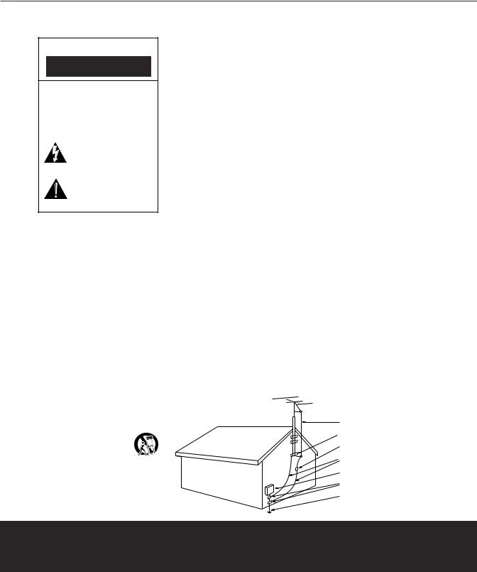
17.If an outside antenna or cable system is connected to the product, be sure the antenna or cable system is grounded so as to provide some protection against voltage surges and built-up static charges. Article 810 of the National Electrical Code, ANSI/NFPA 70, provides information with regard to proper grounding of the mast and supporting structure, grounding of the lead-in wire to an antenna discharge unit, size of grounding conductors, location of antenna-discharge unit, connection to grounding electrodes, and requirements for the grounding electrode. See Figure A.
18.An outside antenna system should not be located in the vicinity of overhead power lines or other electric light or power circuits, or where it can fall into such power lines or circuits. When installing an outside antenna system, extreme care should be taken to keep from touching such power lines or circuits, as contact with them might be fatal.
19.Do not overload wall outlets, extension cords or integral convenience receptacles, as this can result in a risk of fire or electric shock.
Figure A.
Example of Antenna Grounding as per
National Electrical Code ANSI/NFPA 70
20.Never push objects of any kind into this product through openings, as they may touch dangerous voltage points or short-out parts that could result in a fire or electric shock. Never spill liquid of any kind on the product.
21.Do not attempt to service this product yourself, as opening or removing covers may expose you to dangerous voltage or other hazards. Refer all servicing to qualified service personnel.
22.When replacement parts are required, be sure the service technician has used replacement parts specified by the manufacturer or that have the same characteristics as the original part. Unauthorized substitutions may result in fire, electric shock or other hazards.
23.Upon completion of any service or repairs to this product, ask the service technician to perform safety checks to determine that the product is in proper operating condition.
24.The product should be mounted to a wall or ceiling only as recommended by the manufacturer.
Antenna Lead-In Wire
Ground Clamp
Antenna Discharge Unit (NEC Section 810-20)
Grounding Conductors (NEC Section 810-21)
Electric Service Equipment
Ground Clamps
Power Service Grounding Electrode System
(NEC Art 250, Part H)
SAFETY INFORMATION 3

INTRODUCTION
Introduction
Thank you for purchasing the Harman Kardon HKTS 12, with which you’re about to begin many years of listening enjoyment. The HKTS 12 has been custom-designed to provide all the excitement and power of the cinema experience in your own living room.
While sophisticated electronics and state-of- the-art speaker components are hard at work within the HKTS 12, hookup and operation are simple. Color-keyed cables and connections and simple controls make the HKTS 12 easy to use.
To obtain maximum enjoyment from your new home theater speaker system, we urge you to take a few minutes to read through this manual. This will ensure that connections to your receiver or preamp/processor and amplifier or other external devices are made properly. In addition, a few minutes spent learning the functions of the various controls will enable you to take advantage of all the power and refinement the HKTS 12 is able to deliver.
If you have any questions about this product, its installation or operation, please contact your dealer, the best local source of information.
Description and Features
The HKTS 12 is a six-piece home theater speaker system that includes a 12-inch, 150-watt, bass-reflex, powered subwoofer; four identical, 2-way, bass-reflex satellite speakers for use in the left and right front and rear speaker positions; a dedicated, dual-driver, bass-reflex center speaker; wallmount brackets for the four satellites; and all of the speaker cables you need to connect your speakers to your receiver or preamp/ processor and amplifier. The speaker cables and speakers are all color-coded to conform to the new CEA standard. The colorcoding system minimizes confusion, especially when the HKTS 12 system is used with a Harman Kardon receiver.
The HKTS 12 subwoofer is easy to connect to your system, since it’s equipped with a special subwoofer input for use with equipment that has a dedicated subwoofer connection that carries a low-frequency output. It also includes stereo speaker-level inputs and outputs for connection to older receivers and processors that do not have a line-level subwoofer output. Other conveniences include a level control, high-cut (low-pass) filter switch and phase switch for fine-tuning bass response to suit your listening environment and taste, and an efficient
switching system that senses the presence of an audio signal and automatically switches the unit from Standby mode to Active mode.
Wall-mount brackets are included for the satellite speakers, as well as an adjustable support cradle for the center speaker.
Harman Kardon invented the high-fidelity receiver almost fifty years ago. With state- of-the-art features and time-honored circuit designs, the HKTS 12 is a perfect complement to a Harman Kardon receiver or any home theater system.
■Complete home theater speaker system
■Speakers are magnetically shielded for flexible placement near video monitors
■Fully color-coded cables and connections simplify setup
■Both lineand speaker-level inputs offer compatibility with most audio components
■Subwoofer input offers superiorquality bass reproduction when used with any digital audio system that incorporates bass management or programmable crossovers
Powered subwoofer
Four satellites for left, right
and surrounds, with color-key stickers
Wall-mount brackets
One 15' RCA cable for connection to subwoofer (purple)
Three 20' speaker cables for connection to front satellites (red and white) and to center
speaker (green)
Included
One center |
|
channel speaker |
Two 40' speaker cables for connection from |
with adjustable support |
receiver to rear satellites (gray and blue) |
4INTRODUCTION
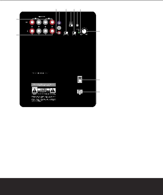
SUB-TS12 SUBWOOFER AMPLIFIER PANEL CONTROLS AND CONNECTIONS
|
|
|
¢£ ∞ §¶•ª |
|
¡ Speaker-Level Inputs |
|||
|
|
|
|
|
|
|
|
|
|
|
|
|
|
|
|
|
™ Speaker-Level Outputs |
™ |
R |
L |
LINE |
|
|
|
|
£ Line-Level Subwoofer (SUB) Input |
IN |
|
|
|
|
||||
|
|
|
LEVEL |
|
|
|
|
|
|
|
|
|
FILTER |
FILTER |
|
¢ Line-Level Full-Range Inputs |
|
|
|
|
|
SUB |
|
CONTROL |
|
|
|
|
|
|
OFF |
ON |
REMOTE |
|
|
|
|
|
|
|
|
SUBWOOFER LEVEL |
|
∞ Phase Switch |
|
|
|
|
|
|
|
§ High-Cut (Low-Pass) Filter Switch |
|
|
|
|
|
L |
GREEN: ON |
|
||
|
|
|
|
PHASE |
RED: STAND-BY |
‚ |
¶ Music-Sense On/Off Switch |
|
|
|
|
|
R |
|
|
||
¡ |
|
|
|
|
|
|
• Filter Remote Control Input |
|
|
|
|
NORMAL REVERSE |
ON |
AUTO |
|
||
|
IMPORTANT: CONNECT STRIPED WIRE TO RED ( |
) SPEAKER TERMINAL. |
|
|
|
ª LED Indicator |
||
|
|
|
|
|
|
|
|
‚ Subwoofer-Level Control |
|
|
|
|
|
|
|
|
⁄ Master Power Switch |
|
|
|
|
|
|
|
|
¤ AC Power Cord |
|
SUB-TS12 HKTS 12 System |
|
|
|
|
|
|
|
|
|
For use with |
|
|
|
|
|
|
|
harman/kardon |
|
|
|
|
|
|
|
|
|
Made in China |
|
|
|
POWER |
|
|
|
|
|
|
|
|
|
|
|
|
|
|
|
|
|
|
⁄ |
|
|
|
|
|
|
|
AC 120V~60Hz |
|
|
|
|
CAUTION |
|
|
|
|
¤ |
|
|
|
RISK OF ELECTRIC SHOCK |
|
|
|
|
|
|
|
|
DO NOT OPEN |
|
|
|
|
|
|
¡ Speaker-Level Inputs: Connect these binding post terminals to the main left and right speaker terminals of your receiver or amplifier, if your receiver or amplifier does not have a line-level subwoofer output. Remember to maintain polarity by connecting the (+) terminal on the receiver/amplifier to the
(+) terminal on the SUB-TS12 subwoofer, and the (–) terminal on the receiver/amplifier to the
(–) terminal on the SUB-TS12 subwoofer.
™ Speaker-Level Outputs: If you are using the Speaker-Level Inputs ¡ on the SUB-TS12, you should connect these binding post terminals to your front left and right speakers, remembering to maintain polarity by connecting the (+) terminal on the SUBTS12 subwoofer to the (+) terminal on the
speaker, and the (–) terminal on the SUBTS12 subwoofer to the (–) terminal on the speaker. If you are not using the SpeakerLevel Inputs ¡, then connect your front left and right speakers directly to your receiver or amplifier. See pages 10 through 12 for further information on speaker connections.
£ Line-Level Subwoofer (SUB) Input:
Connect the subwoofer output of a receiver with digital surround sound decoding, such as Dolby* Digital or DTS®, to this input. This input bypasses the SUB-TS12’s internal crossover circuitry, and should only be used with a filtered signal. If your receiver does not have digital decoding, you should use the
Line-Level Full-Range Inputs ¢ instead.
¢ Line-Level Full-Range Inputs: Connect the line-level subwoofer output or preamp output(s) of your receiver or amplifier to these inputs. If your receiver does not have a separate subwoofer output, use a Y-adaptor (not supplied) to bridge the receiver’s preamp output to the main amp input for that channel, and connect the long end of the adaptor
to the corresponding line-level input on the SUB-TS12. If your receiver has only a single subwoofer output, you may connect it to either the left or right line-level input on the SUB-TS12, and no Y-adaptor is needed.
∞ Phase Switch: This switch determines whether the SUB-TS12 subwoofer’s pistonlike action moves in and out in phase with the main speakers. If the speakers were to
SUB-TS12 SUBWOOFER AMPLIFIER PANEL CONTROLS AND CONNECTIONS 5
 Loading...