

Page 1
HKTS11/230
Version 0.1 September
2010
Service Manual
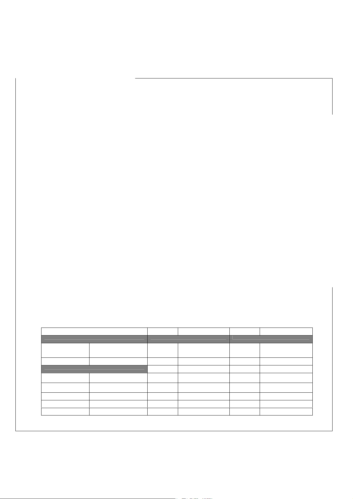
SPECIFICATIONS:
System Satellite Center Channel
Frequency Response (–
6dB) :
Subwoofer Sensitivity : 86dB @ 1 watt/1 meter Sensitivity : 86dB @ 1 watt/1 meter
Amplifier Power (RMS) : 200 watts Tweeter : One 3/4" dome, video-
Bass Driver : 10" woofer, bass-reflex enclosure Midrange
Dimensions 479mm x 340mm x 340mm Dimensions 243mm x 100mm x 92mm Dimensions 102mm x 241mm x 92mm
(H x W x D) : (18-7/8" x 13-3/8" x 13-3/8") (H x W x D) : (9-9/16" x 3-15/16" x 3-5/8") (H x W x D) : (4" x 9-1/2" x 3-5/8")
Weight : 21.8kg (48 lb) Weight : 1kg (2.2 lb) Weight : 1kg (2.2 lb)
25Hz – 20kHz Recommended
Amplifier Power
Range :
Impedance : 8 ohms nominal Impedance : 8 ohms nominal
Driver :
10 – 120 watts Recommended
shielded
Dual 3" drivers, video-
shielded
Amplifier Power
Range :
Tweeter : One 3/4" dome, video-
Midrange
Driver :
10 – 120 watts
shielded
Dual 3" drivers, video-
shielded
Harman Consumer Group Harman/Kardon HKTS11/230
Page 2
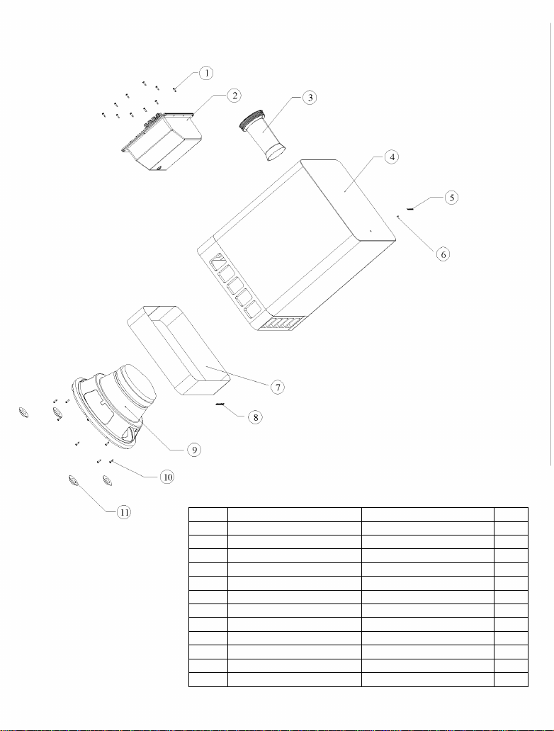
SUB-TS11 harman/kardon
Ref# Description Part Number Qty
1 Amplifier screw 352-AM04020D210 10
2 SUB-TS11 Amplifier 010-0N15-00416
3 Port Tube No t for Sale 1
4 SUB-TS11 Cabinet Not for Sale 1
5 Logo 316-AG-00557 1
6 LED 165-00460MP01 1
7 Grille Not for Sale 1
8 Logo 316-AL-00553 1
9 10" woofer 25PF12DZB-DW02 1
10 Woofer screw 352-FM04020D605 8
11 Foot Pad 320-EVA-00057 4
Page 3

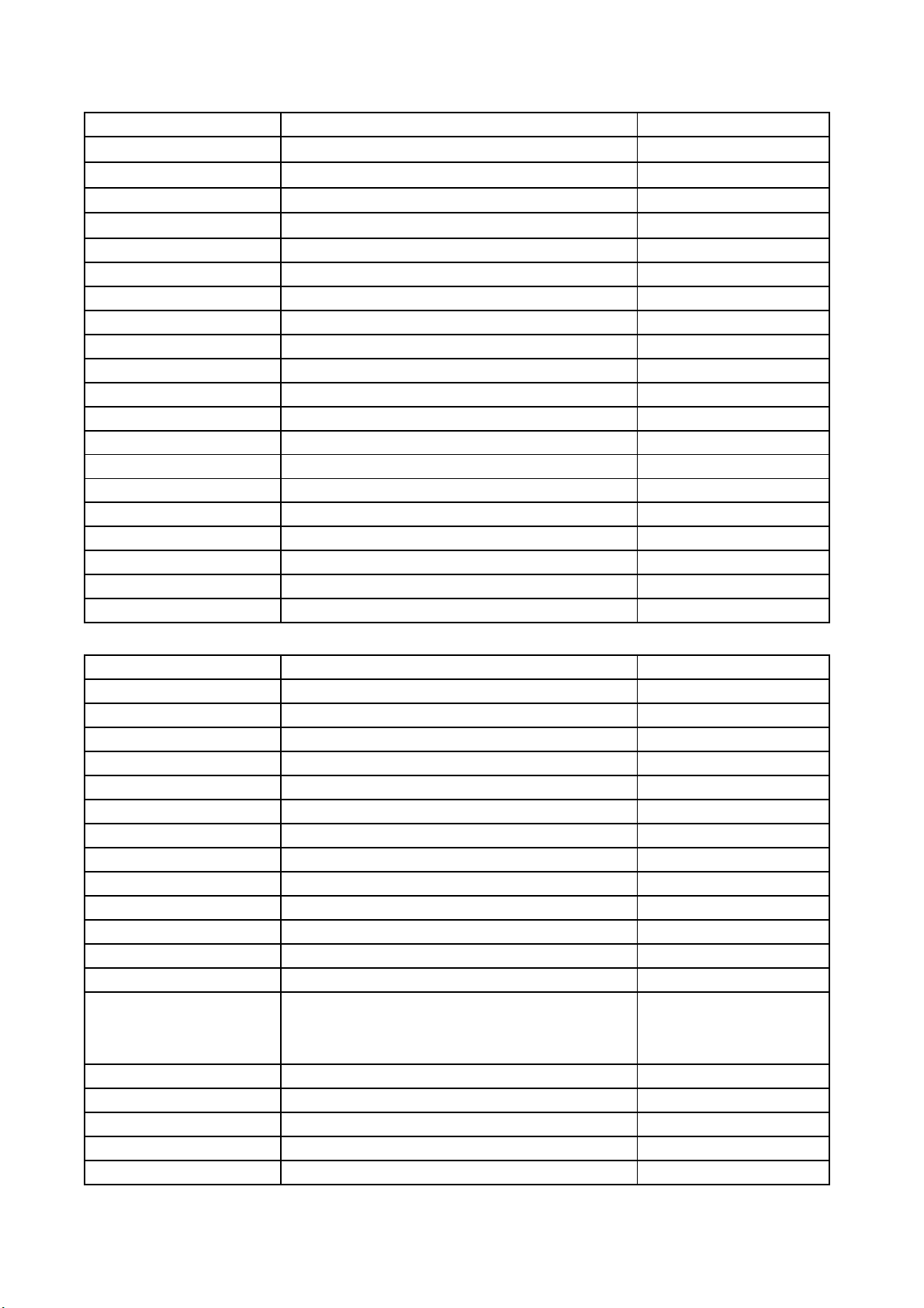
HARMAN/KARDON HKTS11/230V
For Satellites and Center speaker repair use complete units ( item 8 and 9 ) as they not are repairable
mechanical parts and packing
No. Part Number Description Remarks
1 010-0N15-00416 POWER AMPLIFIER
2 N/A CABINET (PORT TUBE INCLUDED)
3 25PF12DZB-DW02 10" SUBWOOFER
4 320-EVA-00057 FOOT FOR SUBWOOFER
5 352-AM04020D210 SCREW FOR SUBWOOFER
6 352-FM04020D605 SCREW FOR SUBWOOFER
7 431-000-01072 EPS PACKING MATERIAL OF SUBWOOFER
8 HKTS11/230 CEN-1 CENTER HKTS 7 3" 16OHM 19MM
9 HKTS11/230 SAT-1 SATELLITE HKTS 7 3" 8OHM 19MM
10 317-PS-00172 PLASTIC TERMINAL COVER ( WALL BRACKET )
11 326-ABS-00108 PLASTIC WALL BRACKET ( WALL BRACKET)
12 326-FE-00109 METAL WALL MOUNTING PLATE ( WALL BRACKET )
13 370-000-00092 RCA CABLE
14 370-000-00256 WIRE CABLE 20 FEET AWG#18-30 RED
15 370-000-00257 WIRE CABLE 20 FEET AWG#18-31 GREEN
16 370-000-00261 WIRE CABLE 20 FEET AWG#18-32 WHITE
17 370-000-00264 WIRE CABLE SAL5009+GARY TUBE
18 370-000-00265 WIRE CABLE SAL5009+BLUE TUBE
19 371-000-00360 SCREW KIT (4pcs 2.3cm long) ( WALL BRACKET )
20 401-000-05003 CARTON FOR SAT
21 431-000-01070 EPE PACKING MATERIAL
22 431-000-01096 EPE PACKING MATERIAL
24 406-000-05067 OWNER MANUAL
25 402-000-01896 GIFT BOX
Harman Consumer group International 2005
Page 4
HARMAN/KARDON HKTS11/230 150W 230V
REFERENCE DESCRIPTION PART NO.
Assy
Assy
Assy
Assy
TF power transformer TT0900305570 150-r4055904
Wire
F501
F501
Tube tube 20mm*40mm 156-h200040
Tube tube 60mm 20? 156-h200060
Knob 46077-W P.V.C 311-ABS-00028
Wire
Wire
Wire
Wire
Wire
Wire
Wire
SW501
Q10,11
FILTER PCB ASS'Y
PCB AMP ASS'Y
PCB PREAMP ASS'Y
CLASS D MODULE
line cord 6FT SP021A H03VVH2-F
Fuse 1.6a 250v VBS UTE-TYPE UL/BSI/VDE
fuse holder HTB-32M UL/CSA/VDE
wire UL1617 120mm BRN 20#
wire UL1617 120mm BRN 20#
051-A00024A
051-A00404B
051-A00416A
051-B00012A
152-v60202603
154-k16006t0
155-620001
162-10121002
162-10126001
wire UL1617 AWG22 150mm RED 162-10152001
wire UL2468 200mm 2.5mmpitch RED/WHT 162-5020d006
wire UL1007#16 550mm#110/#205 0.5T 162-50552003
wire tie 100mm 163-11009
wire tie 160mm 163-11609
Switch ROCK RF-1003-BB4-0
INSULATOR
180-prf1003d
193-201815t2
Preamp
051-A00416A 1/2
REFERENCE DESCRIPTION PART NO.
VR201
to connect D209
W202
JK201 RCA JACK RCA-313G V/R/W 174-0rca313v
W202 Wire connector&base 8 PIN PITCH=2.0mm 175-1b08v01
M201 Wire connector&base 7 PIN PITCH=2.5mm 175-1c07c01
SW201,202,203
U203
U201,202 *I.C074CN ST 190-16t1074cn
Q206
R201,202
R213,214,215,254
R209,212,216,217,218,220,221,2
22,225,228,
229,230,232,235,
240,248,260,270
R231,263,266
R259
R265
R233
R253
VR pot RV16AE-20B2-15K-A54-104(A50K) 115-h503a102
wire 120mm RED/WHT 2PIN 162-50122004
wire UL1007 160/80mm#26
Jack SPK JK BP 8PIN SH0810360G US1.35 174-20810360g
SWITCH SLIDE 6PIN MS7210V
I.C.OPA 4558D
SMD transistor 2SC1815GR TAP
resistor 4.7K 1/2W ±5%CF 52mm TAP
resistor 1K 1/6W ±5%CF26mm TAP
resistor 10K 1/6W ±5%CF26mm TAP
162-a016d001
180-tms7210v
190-06m4558d
192-027c1815gr
110-12472j52
110-16102j26
110-16103j26
resistor 100K 1/6W ±5%CF26mm TAP
resistor 1M 1/6W ±5%CF26mm TAP
resistor 1.2k 1/6W ±5%CF26mm TAP
resistor 130k 1/6W ±5%CF26mm TAP
resistor 150k 1/6W ±5%CF26mm TAP
110-16104j26
110-16105j26
110-16122j26
110-16134j26
110-16151j26
Harman Consumer Group International 2005
Page 5

HARMAN/KARDON HKTS11/230 150W 230V
Preamp
051-A00416A 2/2
REFERENCE DESCRIPTION PART NO.
R252
R262
R237,238
R257
R247,255,256
R223,224
R200,207,258
R219,249,250,251,264
R210,211
R234
R226,227
R203,204,205,206,
C221,222 metalize 0.15U 63V ± 5% MSC TAP 129-a154j633
C218 metalize 0.02uF 63V ± 5% MSC TAP 129-a224j633
C200,204,205,207,208,
210,211,212,214,220,
230,237,
C229 disc capacitor 47P 50V ± 10% TAP 130-2b470k503
C232,242,244,245,246,
252,254,256
C223 mylar capacitor 0.018U 50V ± 5% TAP 132-183j503
C215 mylar capacitor 0.022U 100V ± 5% TAP 132-223ja03
C224 mylar capacitor 0.047U 50V ± 5% TAP 132-473j503
C216 mylar capacitor 0.056U 50V ± 5% TAP 132-563j503
C217 mylar capacitor 0.082U 50V ± 5% TAP 132-823j503
C228
C201,202,206,213,219,
231,241,243,251,253
C234
C225
C233
J,VR202 JUMPER WIRE 26mm TAP 161-506520
Q201207208 transistor 2SC1815GR TAP 192-027C1815gr
D201,202,203,204,205,
206,207,208,214,215,
216,
D213 zener diode 3.3V 1/2W 52mm TAP 199-15000335
D209 diode two colored for stby 165-00460MP01
AMP
resistor 150k 1/6W ±5%CF26mm TAP
resistor 18k 1/6W ±5%CF26mm TAP
resistor 20k 1/6W ±5%CF26mm TAP
resistor 2M 1/6W ±5%CF26mm TAP
resistor 22k 1/6W ±5%CF26mm TAP
resistor 30k 1/6W ±5%CF26mm TAP
resistor 4.7k 1/6W ±5%CF26mm TAP
resistor 47k 1/6W ±5%CF26mm TAP
resistor 5.1k 1/6W ±5%CF26mm TAP
resistor 6.2k 1/6W ±5%CF26mm TAP
resistor9.1k 1/6W ±5%CF26mm TAP
resistor91k 1/6W ±5%CF26mm TAP
disc capacitor220P 50V ± 10% TAP 130-2b221k503
disc capacitor 47P 50V ± 10% TAP 130-2f104z503
electolytic 10U 50V ± 20% TAP
electolytic 10uF 50V ± 20% TAP
electolytic 100uF 16V ± 20% TAP
electolytic 22U 50V ± 20% TAP
electolytic 220U 16V ± 20% TAP
110-16154j26
110-16183j26
110-16203j26
110-16205j26
110-16223j26
110-16303j26
110-16472j26
110-16473j26
110-16512j26
110-16622j26
110-16912j26
110-16913j26
135-3105m50
135-3106m50
135-3107m16
135-3226m50
135-3227m50
diode 100mA 75V SIGNAL 1N4148 ROHM TAP 197-031n4148
051-A00404B 1/3
REFERENCE DESCRIPTION PART NO.
TH1 Thermistor 109-1ttc802j0
R134 resistor 3.3k 2w±5% 7.5m 110-20332jk3
R147 Carbon resistor 0.068O 5w±5% 113-50s68j00
R148 metal film resistor 1.00k 2w ±5% 7.5mm 116-201001jk3x
Harman Consumer Group International 2005
Page 6

HARMAN/KARDON HKTS11/230 150W 230V
resistor 10K 1/4W ±5% CF 26mm TAP
resistor 2.2K 1/4W ±5% CF 26mm TAP
resistor 4.3K 1/4W ±5% CF 26mm TAP
resistor 4.7K 1/4W ±5% CF 26mm TAP
resistor 10K 1/6W ±5% CF 26mm TAP
resistor 100K 1/6W ±5% CF 26mm TAP
resistor 20K 1/6W ±5% CF 26mm TAP
resistor 220O1/6W ±5% CF 26mm TAP
resistor 2.2K 1/6W ±5% CF 26mm TAP
resistor 22K 1/6W ±5% CF 26mm TAP
resistor 33K 1/6W ±5% CF 26mm TAP
resistor 39K 1/6W ±5% CF 26mm TAP
resistor 430K 1/6W ±5% CF 26mm TAP
resistor 47K 1/6W ±5% CF 26mm TAP
resistor 470K 1/6W ±5% CF 26mm TAP
resistor 5.6K 1/6W ±5% CF 26mm TAP
metal film resistor 10K 1/6w ± 1% MF 26mm TAP
metal film resistor 12.0K 1/6w ± 1% MF 26mm TAP
metal film resistor 220O1/6w ± 1% MF 26mm TAP
metal film resistor 22.0K 1/6w ± 1% MF 26mm TAP
AMP
051-A00404B
2/3
REFERENCE DESCRIPTION PART NO.
R501,502 metal film resistor 470O 3W±5% 10mm 116-304700jk2x
FB1,2
C500 mylar capacitor 0.01uF 400V +/-10% 132-103kd00
C501.502
TH1 tube 1?*24mm 156-b010024
W201
RL1
M100
M500
U301
Q501
Q502
D501 diode 6A 800V KBU606G 197-00kbu606g
D110,504 diode IN4004 197-141n4004
R503,504,510
R511
R506
R505
R153
R128,130,149,150,305,
306,308,311,314,319
R122,126,307
R107 resistor 15K 1/6W ±5% CF 26mm 110-16153j26
R145 resistor 1.8K 1/6W ±5% CF 26mm 110-16182j26
R309
R144
R102
R316
R310
R151
R312
R106,129
R127
R152
R160 resostor 620O1/6W ± 5% CF 26mm TAP 110-16621j26
R315 resostor 750O1/6W ± 5% CF 26mm TAP 110-16751j26
R313 resostor 7.5M 1/6W ± 5% CF 26mm TAP 110-16755j26
R301,303
R302
R317
R318
R107,117,122,144,
320,322
Inductor 10w AI YT-C3104-005 1CRHW 354708LTB
Large aluminumec 4.7uF 80V±20% 85?
wire ASS'Y 120mm AWG28
Relay RWH-SH-124D (1600 ohm)
wire connector 2PIN PITCH=3.96mm
wire connector 3PIN PITCH=3.96mm
*I.C TL074CN ST
transistor TIP31C SGS
transistor TIP32C SGS
resistor 1K 1/6W ±5% CF 26mm TAP
disc capacitor 0.1U 50V ±10% TAP 130-2f104z503
120-1000003
138-5478m80
162-50129001
171-urwh124d
175-1d02V01
175-1d03V01
190-16t1074cn
192-161tip31c
192-162tip32c
110-14103j26
110-14222j26
110-14432j26
110-14472j26
110-16102j26
110-16103j26
110-16104j26
110-16203j26
110-16221j26
110-16222j26
110-16223j26
110-16333j26
110-16393j26
110-16434j26
110-16473j26
110-16474j26
110-16562j26
116-161002f26
116-161202f26
116-162200f26
116-162202f26
Harman Consumer Group International 2005
Page 7

HARMAN/KARDON HKTS11/230 150W 230V
disc capacitor 100P 50V SL ± 10% TAP
mylar capacitor 0.01uF 100V ±5% TAP
mylar capacitor 0.01uF 100V ±5% TAP
mylar capacitor 0.027uF 100V ±5% TAP
diode 100mA 75V SIGNAL 1N4148
AMP
051-A00404B
3/3
REFERENCE DESCRIPTION PART NO.
C302,303,306
C305,317 mylar capacitor 0.01U 50V ±5% TAP 132-103j503
C103,104
C123,503,504
C143
C319,321 electrolytic 10uF 50V ±20% TAP 135-3106m50
C114,115 electrolytic 100U 10V ±20% TAP 135-3107m10
C507,508 electrolytic 100U 35V ±20% TAP 135-3107m35
C509 electrolytic 2.2U 50V ±20% TAP 135-3225m50
C304 electrolytic 22U 16V ±20% TAP 135-3226m16
C505,506 electrolytic 22U 50V ±20% TAP 135-3226m50
C118 electrolytic 220U 16V ±20% TAP 135-3227m16
C318 electrolytic 47U 16V ±20% TAP 135-3476m16
JUMPER WIRE 26mm TAP 161-506520
Q108,109,113,301,302 transistor 2SC1815GR TAP 192-027c1815gr
Q111 transistor 2SC2235Y TAP 192-027c2235y
Q101,107,112 transistor 2SA1015GR TAP 192-028a1015gr
Q114,115 transistor 2SN5551 TAP 192-1572n5551
Q503 trans 2SN5401 PNP 350V 500mA TO-92 192-1582n5401
Q102,103,104,105,
143,301,302
D101 zener diode 6.2V 1/2W 52mm TAP 199-15000625
D502 zener diode 16V 1/2W 52mm TAP 199-15001605
CLASS D MODULE
051-B00012A 1/2
130-sl101k503
132-103ja03
132-104ja03
132-273ja03
197-013n4148
REFERENCE DESCRIPTION PART NO.
L1
L2
C16,17
Q10
Q11
R2,11,29,30 SMD resistor 1.00K 1206 5% 118-12061001j
R7,9,25 SMD resistor 10.0K 1206 5% 118-12061002j
R22,23 SMD resistor 10.0O 1206 5% 118-120610r0j
R31,32,33,34,35,36,37,
38,39,40,41,42,43,44,
45,46
R26 SMD resistor 20.0K 1206 5% 118-12062002j
R6,13,16 SMD resistor 2.20K 1206 5% 118-12062201j
Indictor Ferrire core LS-A6206-ST EFD-30
Indictor 35uH Ferrire core 25 Milliohm
bobbin (NI-ZN)RC6*30
black PCB TUBE ? 13
2UEW COPER WIRE ?1.0
Non-Polar EC. 10uF 100W 20% 128-e106ma01
Wire Connector&Base40PIN PITCH=2.54mm HR2*40
Transistor FET IRF9640 IR P-CH T0220
Transistor FET IRF640 IR P-CH T0220
PCB 171mm*141mm FR4 104-ds15000v
SMD resistor 1.20K 1206 5% 118-12061201j
122-14121m4191
122-14350j4180
123-11rc6*30wd
157-p013000
160-g2uew100
175-9f40hr2
192-232irf9640
192-233irf640
Harman Consumer Group International 2005
Page 8

HARMAN/KARDON HKTS11/230 150W 230V
SMD zener diode 5.6V 5% PHILIPS BZX84-C5V6
SMD zener diode 12V 5% PHILIPS BZX84-C12
SMD zener diode 15V 5% PHILIPS BZX84-C15
CLASS D MODULE
051-B00012A
2/2
REFERENCE DESCRIPTION PART NO.
R10 SMD resistor 2.70K 1206 5% 118-12062701j
R24 SMD resistor 300.0O 1206 5% 118-12063000j
R14,15,27,28 SMD resistor 3.30K 1206 5% 118-12063301j
R3 SMD resistor 39.0K 1206 5% 118-12063902j
R8 SMD resistor 470O 1206 5% 118-12064700j
R1,5,12 SMD resistor 4.70K 1206 5% 118-12064701j
R17 SMD resistor 47.0K 1206 5% 118-12064702j
R4 SMD resistor 4.70M 1206 5% 118-12064704j
R20,21 SMD resistor 47.0O 1206 5% 118-120647r0j
C4 SMD cakpacitor 100pF 50V 10% 1206 NPO 141-c0101k50
C5 SMD cakpacitor 22pF 50V 10% 1206 SMT NPO 141-c0220k50
C6 SMD cakpacitor 560pF 50V 10% 1206 NPO 141-c0561k50
C2,3,7,8,9,10,11,15 SMD cakpacitor 1206 Y5V 0.1uF 50V ± 20% 141-c5104m50
C13 SMD cakpacitor 0.022uF 50V 10% 1206 X7R 141-c7223k50
C12,14 SMD cakpacitor 0.1uF 100V 10% 1210 X7R 141-d7104ka0
C1,18,19,20 SMD cakpacitor 0.1uF 250V 10% 1210 X7R 141-d7104kb5
IC1 SMD I.C. TL072CDT SGS THOMSON 190-16tl072dts
Q1,4,5 SMD transistor 2SC2412K-T146Q/R 192-09124126qs
Q2,8 SMD transistor 2SC3906K-T146R ROHM 192-09139066rs
Q7,9 SMD transistor 2SA1037K-T146Q/R ROHM 192-09210376qs
Q3,6 SMD transistor 2SC1514K-T146R ROHM 192-09215146rs
D1,2,3,4,5,6 SMD diode RLS4148-TE11 ROHM 197-03rls4148s
Z1,2
199-15000563s
Z5,6
Z3,4
Filter
051-A00024A 1/1
199-15001203s
199-15001503s
REFERENCE DESCRIPTION PART NO.
L501
C499 mylar capacitor 0.1uF 275V± 10% VDE 132-104kb70
C498 mylar capacitor 0.22uF 275V±10% 132-224kb70
inductor RT251510*393N 2A
122-14393ma02
Harman Consumer Group International 2005
Page 9

Page 10

SUB-TS11
SUB TS11
Test Set Up and Procedure
harman/kardon
Equipment needed:
• Function/signal generator/sweep generator
• Integrated Amplifier
• Multimeter
• Speaker cables
Initial Control Settings:
• Power Switch OFF; Filter OFF
• Level MIN (Full CCW)
• Phase, Auto/On switches do not matter
General Unit Function (UUT = Unit Under Test)
1) From the signal generator, connect one line level (RCA) cable to the Subwoofer Line Level Input jacks L/R
on the UUT. Use a Y-cable from a mono source if necessary to connect to both inputs. Do not connect to
the single, purple SUB input.
2) Turn on generator; adjust to 60mV, 50 Hz.
3) Plug in UUT; turn the power switch ON. Turn LEVEL control full clockwise (MAX)
4) LED should turn from Amber to Blue (on top of UUT); immediate and vigorous bass response should be
heard and felt from port tube opening.
5) Turn off generator, turn LEVEL control full counterclockwise (MIN), and disconnect RCA cable.
6) Connect one pair
of speaker cables to Speaker Level input terminal (IN) on UUT. Cables should be
connected to an integrated amplifier fed by the signal generator.
7) Turn on generator and adjust so that speaker level input at the amplifier is 1.2V, 50 Hz. Turn LEVEL control
full clockwise.
8) LED should turn from Amber to Blue; immediate and vigorous bass response should be heard and felt from
the port tube opening.
Sweep Function
1) Follow steps 6-8 above, using a sweep generator as a signal source.
2) Sweep generator from 20Hz to 300Hz. Listen to the cabinet and drivers for any rattles, clicks, buzzes or
any other noises. If any unusual noises are heard, remove woofers and test.
Driver Function
1) Remove woofer from cabinet; detach + and - wire clips.
2) Check DC resistance of woofer; it should be 2.8 ohms ±10%
3) Connect a pair of speaker cables to driver terminals. Cables should be connected to an integrated amplifier
fed by a signal generator. Turn on generator and adjust so that speaker level output is 5.0V.
4) Sweep generator from 20Hz to 1kHz. Listen to driver for any rubbing, buzzing, or other unusual noises.
Page 11

Page 12

EuP compliant version
added Sept 2010, 1 of 4.
Page 13

EuP compliant version
added Sept 2010. 2 of 4.
Page 14

EuP compliant version
added Sept 2010. 3 of 4.
Page 15

1
EuP compliant version added
Sept 2010, HKTS 2. 4 of 4.
2
3
4
D1
+6V
R13
10K
Q02
8550S
1N4007
D3
1N4007
D5
1N4007
D7
1N4007
R9
22K
GND
R17
2k
A A
C6
0.22u
17mH
B B
C19
0.22u
RV1
14D471K
C C
2
CON3
Header 2B
D D
RT1
NTC 5D-13
1
GND
C11L2
152PF
GND
2
1
CON1
Header 2B
1
C5
152PF
C15
472
K1
Relay-SPST
Q1
8050S
R16
100K
-6V
C1
15uf/400V
C16
0.1u/25V
C18
47uF/25V
R7
100K
Q04
8550S
Q03
8050S
2
C2
4.7n/500V
D8
SF16
D4
1N4148
R15
22k
HI VOL
R3
1.1meg
R4
1.1meg
1
2
3
C20
680P
std
ICSP
IC1
OB
VCC
GND
CT4FB
THX203H
OC
OC
IS
R1
300k
8
7
6
5
C22
22n
R2
300k
D6
UF1010
R11
2R
C7
470PF/1k
R12
2R
1
W1
2
W2
3
4
W3
5
TR
4
3
C3
152PF
TR1
op1
PC817 A
D2
GND
UF302
10
C9
470u
8
GND
W4
S1
S2
TRANSFORMER
Title
A4
Date: 2008/11/3 Sheet of
File: E:\\..\standby.SchDoc Drawn By:
3
D9
6
UF302
R6
2k
1
2
-6V
Number RevisionSize
C12
470u
2 1
C4
0.1u
R5
12k
C21
0.1u
3
U1
ST TL431
C17
0.1u
R10
10k
1
3
R8
38.3k
R14
10k
2
4
C10
470u
L1
IND1
C14
470u
GND
+6V
C8
0.1u
GND
C13
0.1u
-6V
std
+6V
-6V
4
CON2
1
2
3
4
H
eader 4
Page 16

EuP compliant version added
Sept 2010. HKTS 11. 1 of 4.
Page 17

EuP compliant version added
Sept 2010. HKTS 11. 2 of 4.
Page 18

EuP compliant
version added Sept
2010. HKTS 11.
3 of 4.
Page 19

1
EuP compliant version
added Sept 2010.
HKTS 11. 4 of 4.
2
3
4
D1
+6V
R13
10K
Q02
8550S
1N4007
D3
1N4007
D5
1N4007
D7
1N4007
R9
22K
GND
R17
2k
A A
C6
0.22u
17mH
B B
C19
0.22u
RV1
14D471K
C C
2
CON3
Header 2B
D D
RT1
NTC 5D-13
1
GND
C11L2
152PF
GND
2
1
CON1
Header 2B
1
C5
152PF
C15
472
K1
Relay-SPST
Q1
8050S
R16
100K
-6V
C1
15uf/400V
C16
0.1u/25V
C18
47uF/25V
R7
100K
Q04
8550S
Q03
8050S
2
C2
4.7n/500V
D8
SF16
D4
1N4148
R15
22k
HI VOL
R3
1.1meg
R4
1.1meg
1
2
3
C20
680P
std
ICSP
IC1
OB
VCC
GND
CT4FB
THX203H
OC
OC
IS
R1
300k
8
7
6
5
C22
22n
R2
300k
D6
UF1010
R11
2R
C7
470PF/1k
R12
2R
1
W1
2
W2
3
4
W3
5
TR
4
3
C3
152PF
TR1
op1
PC817 A
D2
GND
UF302
10
C9
470u
8
GND
W4
S1
S2
TRANSFORMER
Title
A4
Date: 2008/11/3 Sheet of
File: E:\\..\standby.SchDoc Drawn By:
3
D9
6
UF302
R6
2k
1
2
-6V
Number RevisionSize
C12
470u
2 1
C4
0.1u
R5
12k
C21
0.1u
3
U1
ST TL431
C17
0.1u
R10
10k
1
3
R8
38.3k
R14
10k
2
4
C10
470u
L1
IND1
C14
470u
GND
+6V
C8
0.1u
GND
C13
0.1u
-6V
std
+6V
-6V
4
CON2
1
2
3
4
H
eader 4
Page 20

Page 21

Page 22

Page 23

Page 24

Page 25

Page 26

 Loading...