

Page 1
CONTENTS
EXPLODED VIEW AND PARTS, BDS 5 70 48
OWNER’S MANUAL 2-34
harman/kardon Service Manual
HK BDS 270
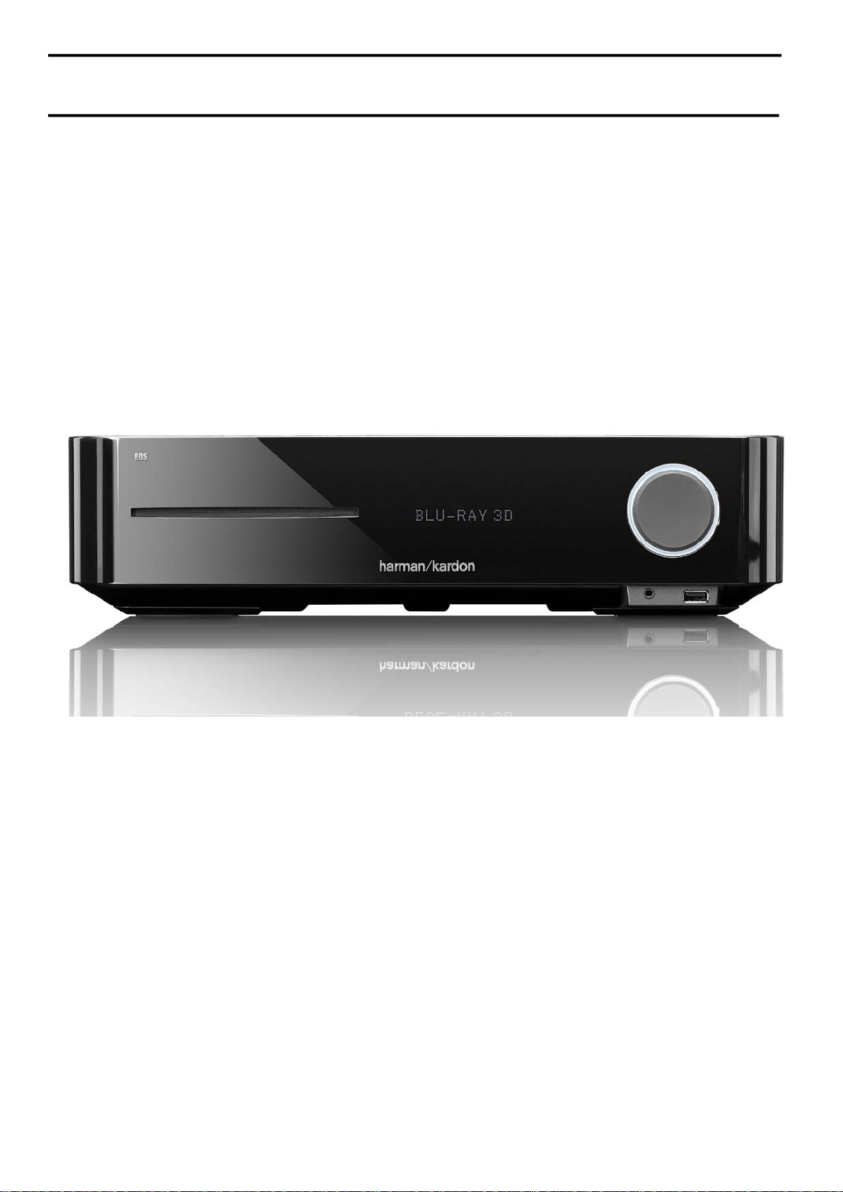
2.1-channel 3-D Blu-r ay home cinema receiver
HK BDS 570
5.1-channel 3-D Blu-r ay home cinema receiver
TROUBLESHOOTING GUIDE 27
BASIC SPECIFICATIONS 33
SOFTWARE UPGRADE PROCESS 35
TROUBLESHOOTING CHARTS 36
Released EU2011 Harman Consumer Group, Inc. Rev 1, 10/2011
8500 Balboa Boulevard
Northridge, California 91329
EXPLODED VIEW AND PARTS, BDS 270 50
ELECTRICAL PARTS LIST 53
PCB LAYOUT DRAWINGS 57
WIRING DIAGRAM 65
SCHEMATIC DIAGRAMS 66-90
Page 2

BDS 270/BDS 570
harman/kardon
BDS 270 + 570 Service Manual
Page 2 of 90
Blu-ray Disc™ receiver
Owner’s Manual
Page 3

BDS 270/BDS 570 Table of Contents
harman/kardon
BDS 270 + 570 Service Manual
Page 3 of 90
IMPORTANT SAFETY INSTRUCTIONS 3
INTRODUCTION 4
VERIFY LINE VOLTAGE BEFORE USING 4
UNPACKING 4
INSTALLATION LOCATION 4
CLEANING 4
MOVING THE RECEIVER 4
SUPPLIED ACCESSORIES 4
RECEIVER FRONT-PANEL CONTROLS 5
RECEIVER REAR-PANEL CONNECTIONS 6
REMOTE CONTROL FUNCTIONS 8
CONNECTIONS 10
PREPARING THE REMOTE CONTROL 14
SETTING UP THE RECEIVER 15
USING THE RECEIVER 18
USING THE DISC PLAYER 20
LISTENING TO YOUR iPod/iPhone DEVICE 22
USING THE RADIO 22
LISTENING TO AUDIO SOURCES 23
PLAYING FILES FROM USB DEVICES AND CD DATA DISCS 23
USING PLAYLISTS 25
TROUBLESHOOTING 26
AUX COMPONENT REMOTE-CONTROL CODE LIST 27
SPECIFICATIONS 32
2
Page 4
Important Safety Instructions
harman/kardon
BDS 270 + 570 Service Manual
Page 4 of 90
1. Read these instructions.
2. Keep these instructions.
3. Heed all warnings.
4. Follow all instructions.
5. Do not use this apparatus near water.
6. Clean only with a dry cloth.
7. Do not block any ventilation openings.Install in accordance with the manufacturer’s instructions.
8. Do not install near any heat sources such as radiators, heat registers, stoves or other apparatus (including
amplifiers) that produce heat.
9. Do not defeat the safety purpose of the polarized or grounding-type plug. A polarized plug has two blades with one
wider than the other. A grounding-type plug has two blades and a third grounding prong. The wide blade or the
third prong is provided for your safety. If the provided plug does not fit into your outlet, consult an electrician for
replacement of the obsolete outlet.
10. Protect the power cord from being walked on or pinched, particularly at plugs, convenience receptacles and the
point where they exit from the apparatus.
11. Only use attachments/accessories specified by the manufacturer.
12. Use only with the cart, stand, tripod, bracket or table specified by the manufacturer or sold with the
apparatus. When a cart is used, use caution when moving the cart/apparatus combination to avoid
injury from tip-over.
13. Unplug this apparatus during lightning storms or when unused for long periods of time.
14. Refer all servicing to qualified service personnel. Servicing is required when the apparatus has been damaged
in any way, such as power supply cord or plug is damaged, liquid has been spilled or objects have fallen into the
apparatus, or the apparatus has been exposed to rain or moisture, does not operate normally or has been dropped.
15. Do not expose this apparatus to dripping or splashing and ensure that no objects filled with liquids, such as vases,
are placed on the apparatus.
16. To completely disconnect this apparatus from the AC Mains, disconnect the power supply cord plug from the AC
receptacle.
17. The mains plug of the power supply cord shall remain readily operable.
18. Do not expose batteries to excessive heat such as sunshine, fire or the like.
CAUTION
RISK OF ELECTRIC SHOCK. DO NOT OPEN.
THE LIGHTNING FLASH WITH AN ARROWHEAD SYMBOL,
WITHIN AN EQUILATERAL TRIANGLE, IS INTENDED TO
ALERT THE USER TO THE PRESENCE OF UNINSULATED
“DANGEROUS VOLTAGE” WITHIN THE PRODUCT’S
ENCLOSURE THAT MAY BE OF SUFFICIENT MAGNITUDE TO
CONSTITUTE A RISK OF ELECTRIC SHOCK TO PERSONS.
THE EXCLAMATION POINT WITHIN AN EQUILATERAL
TRIANGLE IS INTENDED TO ALERT THE USER TO
THE PRESENCE OF IMPORTANT OPERATING AND
MAINTENANCE (SERVICING) INSTRUCTIONS IN THE
LITERATURE ACCOMPANYING THE PRODUCT.
WARNING: TO REDUCE THE RISK OF FIRE OR ELECTRIC
SHOCK, DO NOT EXPOSE THIS APPARATUS TO RAIN OR
MOISTURE.
For Products That Transmit and
Receive RF Energy:
FCC Regulations (USA Only)
FCC Information For Users
This device complies with Part 15 of the FCC Rules. Operation
is subject to the following two conditions: (1) This device
may not cause harmful interference; and (2) this device must
accept any interference received, including interference that
may cause undesired operation.
Radio and Television Interference
This equipment has been tested and found to comply with
the limits for a Class B digital device, pursuant to Part 15
of the FCC Rules. These limits are designed to provide
reasonable protection against harmful interference in a
residential installation. This equipment generates, uses and
can radiate radio frequency energy and, if not installed and
used in accordance with the instructions, may cause harmful
interference to radio communications. However, there is no
guarantee that interference will not occur in a particular
installation. If this equipment does cause interference to radio
or television reception, which can be determined by turning
the equipment off and then on, the user is encouraged to try
to correct the interference by one or more of the following
measures:
• Increase the separation between the equipment and
receiver.
• Connect the equipment to a different outlet so that the
equipment and receiver are on different branch circuits.
• Consult the dealer or an experienced radio/TV technician
for help.
NOTE: Changes or modifications not expressly approved
by Harman could void the user’s authority to operate the
equipment.
IC Statement and Warning (Canada Only)
This Class B digital apparatus complies with Canadian ICES-
003. Cet appareil numérique de la classe B est conforme à la
norme NMB-003 du Canada.
For Canadian Model
This Class B digital apparatus complies with Canadian
ICES-003.
Modèle pour les Canadien
Cet appareil numérique de la classe B est conforme à la
norme NMB-003 du Canada.
For Products with Radio Receivers
That Can Use an External Antenna:
CATV or Antenna Grounding
If an outside antenna or cable system is connected to this
product, be certain that it is grounded so as to provide some
protection against voltage surges and static charges. Section
810 of the National Electrical Code, ANSI/NFPA No. 70-1984,
provides information with respect to proper grounding of the
mast and supporting structure, grounding of the lead-in wire
to an antenna discharge unit, size of grounding conductors,
location of antenna discharge unit, connection to grounding
electrodes and requirements of the grounding electrode.
Note to CATV System Installer:
This reminder is provided to call the CATV (cable TV) system
installer’s attention to article 820-40 of the NEC, which
provides guidelines for proper grounding and, in particular,
specifies that the cable ground shall be connected to the
grounding system of the building, as close to the point of
cable entry as possible.
For CD/DVD/Blu-ray Disc™ Players:
Caution:
This product uses a laser system. To prevent direct exposure
to the laser beam, do not open the cabinet enclosure or defeat
any of the safety mechanisms provided for your protection.
DO NOT STARE INTO THE LASER BEAM. To ensure proper use
of this product, please read the owner’s manual carefully and
retain it for future use. Should the unit require maintenance
or repair, please contact your local Harman Kardon service
center. Refer servicing to qualified personnel only.
For Products That Include Batteries:
Instructions for Users on Removal and Disposal of
Used Batteries.
CAUTION
Risk of explosion if battery is incorrectly replaced.
Replace only with the same or equivalent type.
Alkaline batteries are considered nonhazardous.
Rechargeable batteries (i.e., nickel cadmium, nickel metalhydride, lithium and lithium-ion) are considered hazardous
household materials and may pose an unnecessary health
and safety risk.
In the European Union and other locations, it is illegal to
dispose of any battery with household trash. All batteries
must be disposed of in an environmentally sound manner.
Contact your local waste management officials for information
regarding the environmentally sound collection, recycling and
disposal of used batteries.
To remove the batteries from your equipment or remote
control, reverse the procedure described for inserting
batteries in the owner’s manual.
For products with a built-in battery that lasts for the lifetime of
the product, removal may not be possible for the user. In this
case, recycling or recovery centers handle the dismantling of
the product and the removal of the battery. If, for any reason, it
becomes necessary to replace such a battery, this procedure
must be performed by authorized service centers.
Page 5
BDS 270/BDS 570
harman/kardon
BDS 270 + 570 Service Manual
Page 5 of 90
Introduction, Verify Line Voltage Before Using,
Unpacking, Installation Location, Cleaning,
Moving the Receiver and Supplied Accessories
Introduction
Please register your product on our Web site at www.harmankardon.com.
Note: You’ll need the product’s serial number. At the same time, you can
choose to be notified about our new products and/or special promotions.
Thank You for Choosing Harman Kardon Products!
In the years since Harman Kardon engineers invented the high-fidelity receiver, we have
taken to heart this philosophy: Bringing the joy of home entertainment to as many people
as possible, adding performance and ease-of-use features that enhance the experience.
The BDS series of home entertainment systems offers a complete home entertainment
solution with a wealth of listening and viewing options in one sleek receiver.
To get the maximum enjoyment from your new BDS receiver we urge you to read this
manual thoroughly and refer back to it as you become more familiar with your new
receiver’s features and their operation.
If you have any questions about this product, its installation or its operation, please
contact your retailer or custom installer, or visit our Web site at www.harmankardon.com.
Verify Line Voltage Before Using
Your BDS receiver has been designed for use with 110 – 240-volt, 50Hz/60Hz AC current
and includes a detachable IEC power cable intended for use in the region where the
receiver is sold.
Connection to a line voltage other than that for which the unit is intended can create
a safety and fire hazard and may damage the units. If you have any questions about
the voltage requirements for your specific model or about the line voltage in your area,
contact your dealer before plugging the unit into a wall outlet.
Unpacking
The carton and shipping materials used to protect your new receiver during shipment
were specially designed to cushion it from shock and vibration. We suggest that you
save the carton and packing materials for use in shipping if you move or if the unit ever
needs repair.
To minimize the size of the carton in storage, you may wish to flatten it. You can do it by
carefully slitting the tape seams on the carton’s bottom and collapsing it. You can store
cardboard inserts in the same manner. Packing materials that cannot be collapsed should
be saved along with the carton in a plastic bag.
If you do not wish to save the packaging materials, please note that the carton and
other sections of the shipping-protection materials are recyclable. Please respect the
environment and discard those materials at a local recycling center.
Remove the protective plastic film from the front-panel lens. Leaving the film in place will
affect the performance of your remote control.
Installation Location
• To ensure proper operation and to avoid the potential for safety hazards, place the
unit on a firm and level surface. When placing the unit on a shelf, be certain that the
shelf and any mounting hardware can support the weight of the product.
• Provide proper space both above and below the unit for ventilation. If this product will
be installed in a cabinet or other enclosed area, make certain that there is sufficient
air movement within the area. Under some circumstances, a fan may be required.
• Do not place the unit directly on a carpeted surface.
• Avoid installation in extremely hot or cold locations or in an area that is exposed to
direct sunlight or heating equipment.
• Avoid moist or humid locations.
• Do not obstruct the fan vents on the rear panel or the ventilation slots on the top and
sides of the unit or place objects directly over or next to them.
• Do not place the receiver directly on top of a product that generates excessive heat.
• Due to the heat generated by the receiver there is the remote possibility that the
rubber padding on the bottom of the unit’s feet may leave marks on certain wood
or wood-veneer materials. Use caution when placing the unit on soft woods or
other materials that heat or heavy objects may damage. Some surface finishes
may be particularly sensitive to absorbing such marks, due to a variety of factors
beyond Harman Kardon control, including the nature of the finish, cleaning materials
used, normal heat and vibration caused by the use of the product, or other factors.
Your warranty will not cover this type of damage to furniture, so exercise caution
in choosing an installation location for the component and in performing normal
maintenance practices.
• Your new Harman Kardon Blu-ray Disc
™
receiver requires a broadband Internet
connection for BD-Live™ interactivity.
Cleaning
When the receiver gets dirty, wipe it with a clean, soft, dry cloth. If necessary, and only
after unplugging the AC power cord, wipe it with a soft cloth dampened with mild soapy
water, then a fresh cloth with clean water. Wipe it dry immediately with a dry cloth. NEVER
use benzene, aerosol cleaners, thinner, alcohol or any other volatile cleaning agent. Do
not use abrasive cleaners, as they may damage the finish of metal parts. Avoid spraying
insecticide near the unit.
Moving the Receiver
Before moving the receiver, disconnect any interconnection cords to other components,
and disconnect the unit from its AC outlet.
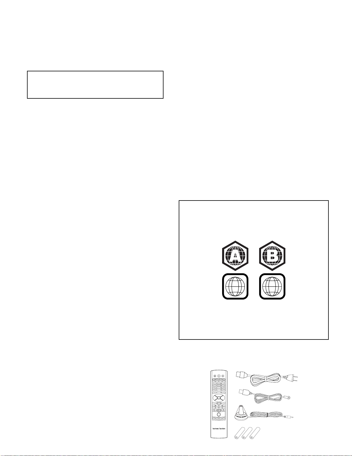
NOTE: The built-in Blu-ray Disc/DVD player in your BDS receiver is designed
and manufactured for compatibility with region management information that is
encoded on most Blu-ray Disc recordings and DVD recordings:
• BDS receivers sold in the USA are designed only for playback of discs
with Blu-Ray Disc Region Code A and DVD Region Code 1 information, or
for discs that do not contain any region code information.
1
2
• BDS receivers sold in Europe are designed only for playback of discs with
Blu-ray Disc Region Code B and DVD Region Code 2 information, or for
discs that do not contain region code information.
If there is a region code on a disc other than the one your BDS player is designed
for, it will not play in your BDS receiver.
Supplied Accessories
If any of these items are missing, please contact Harman Kardon Customer Service via
www.harmankardon.com.
EJECT
TV
POWER
iPOD
RADIO
AUX
Remote Control AC Power Cord
DISC
SETTINGS
1
4
7
CLEAR
HOME
EXIT
+ +
VOLUME
PROGRAM
BOOKMARK
A - B
REPEAT
DISPLAY
2
3
5
6
8
9
0
FIND
SURROUND
OPTIONS
OK
POP-UP
TOP MENU
CHANNEL
MUTE
––
ZOOM
THUMBNAIL
FM Antenna
EzSet/EQ
Microphone
™
4
AAA Batteries
Page 6
BDS 270/BDS 570
harman/kardon
BDS 270 + 570 Service Manual
Page 6 of 90
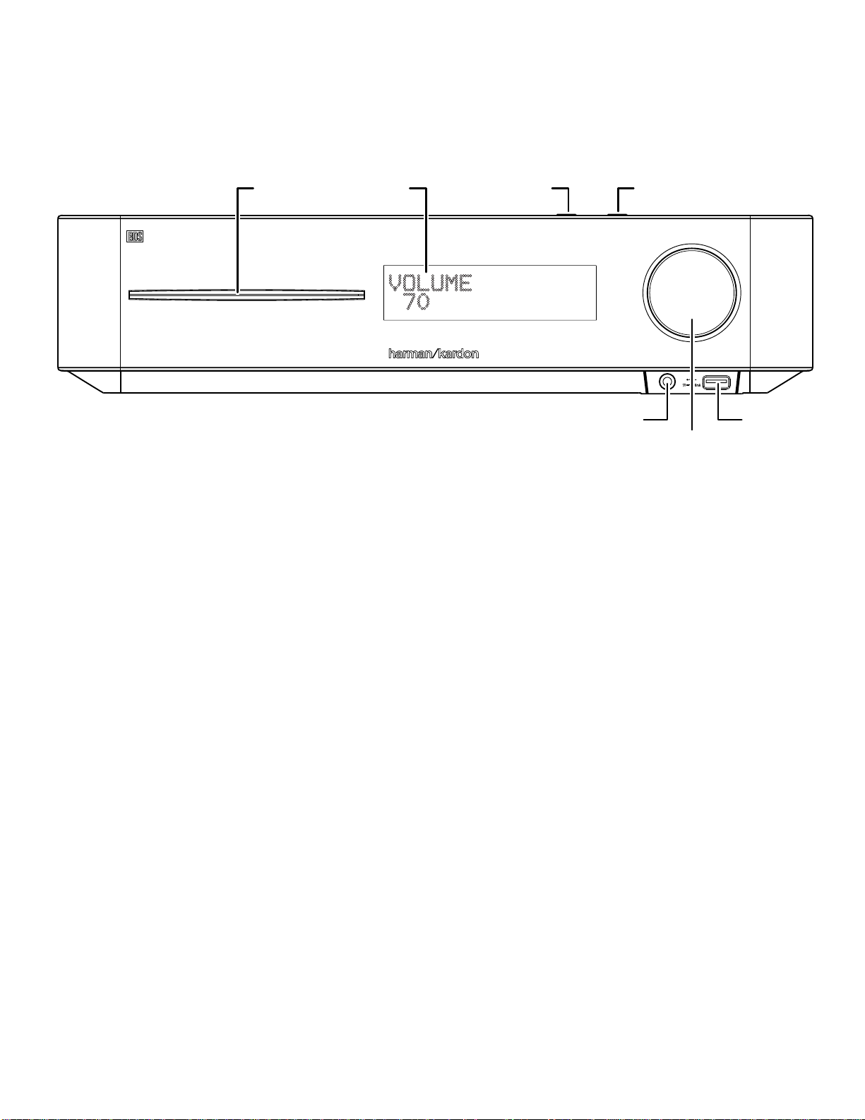
Receiver Front-Panel Controls
Receiver Front-Panel Controls
Disc Slot Information Display
Disc slot: Insert a compatible disc into the slot. The BDS receiver’s disc player will
accept 5-inch (12cm) and 3-inch (8cm) discs.
Information display: Various messages appear on this display in response to
commands and in order to show the audio/video that is playing, the BDS receiver’s
settings or other aspects of the BDS receiver’s status as described throughout this
manual.
Eject button (on top of unit): Press this button to eject a disc from the BDS
receiver’s built-in disc player. Before pressing this button, make sure no objects are
blocking the disc-slot opening. NOTE: If you do not remove the ejected disc within
90 seconds, it will automatically re-load back into the disc player for protection.
Standby button (on top of unit): This button toggles the receiver between the On
and Standby modes.
Power indicator: This LED surrounds the Standby button. When the BDS receiver
is plugged into AC power, the LED turns amber to indicate that the receiver is in
Standby mode (ready to be turned on). When you turn the BDS receiver on (by the
Standby button or the remote control’s Power button), the LED turns white.
Eject Button
(on top panel)
Headphone Jack
Headphone jack: Insert the 1/8-inch (3.5mm) stereo mini connector from a set
of headphones into this jack. NOTE: When a plug is inserted into the Headphone
jack, the BDS receiver’s speaker outputs automatically mute; the HDMI audio output
remains active.
Volume control: Rotate the disc clockwise to raise the volume; rotate
counterclockwise to lower the volume. The volume level will appear on the
Information display and on the on-screen menu.
IMPORTANT: Do not turn the receiver’s Volume control up to or past the point where
the audio from the speakers becomes distorted. Doing so can damage the speakers.
USB 2.0 port: Gently insert a flash drive or HDD disk drive with a USB Standard-A
cable to this port.
IMPORTANT: Do not connect a PC or other USB host/controller to this port, or
you may damage both the BDS receiver and the other device.
Orient the device’s plug so it fits all the way into the BDS receiver’s USB connector.
You may insert or remove the device at any time – there is no installation or ejection
procedure.
Standby Button
(on top panel)
USB Port
Volume Control
5
Page 7
BDS 270/BDS 570
harman/kardon
BDS 270 + 570 Service Manual
Page 7 of 90
Receiver Rear-Panel Connections
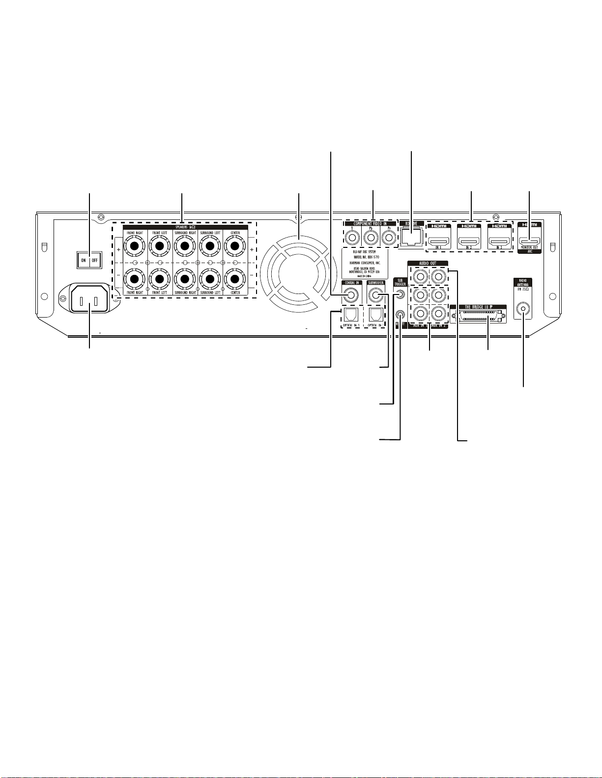
Receiver Rear-Panel Connections
Main
Power Switch
AC Power
Connector
Speaker
Connectors
Fan
Vents
Optical
Digital Input
Connectors
Coaxial
Digital Input
Connector
Component
Video Input
Connector
Subwoofer
Output
Connector
Subwoofer
Trigger
Connector
BD-Live
Connector
Analog
Audio Input
Connectors
HDMI Input
Connectors
The Bridge IIIP
Connector
HDMI
Monitor Out
Connector
FM Antenna
Connector
Remote
IR Input
Connector
Analog
Audio Output
Connector
6
Page 8

BDS 270/BDS 570
harman/kardon
BDS 270 + 570 Service Manual
Page 8 of 90
Receiver Rear-Panel Connections
NOTE: See the Connections section, on page 10, for detailed information about
making connections.
Main Power switch: This mechanical switch turns the BDS receiver’s power supply
on or off. After you have made and verified all connections (see the Connections
section, on page 10), set this switch to the “On” position. During normal use you will
usually leave this switch set to On; it cannot be turned on or off using the remote
control. To conserve energy when you’re not going to be using the receiver for an
extended period of time, set this switch to “Off.”
AC Power connector: After you have made and verified all other connections, plug
the supplied AC power cord into this input and into an unswitched AC outlet.
Speaker connectors: Use the speaker wires supplied with the speakers to connect
the satellite and center speakers to the proper terminals.
• The BDS 570 receiver (shown) has connections for five speakers: front left, front
right, surround left, surround right and center.
• The BDS 270 receiver (not shown) has connections for two speakers: front left
and front right.
See Connections, on page 10, for more information.
Fan vents: These vents are used by the receiver’s fan to cool the unit. Maintain a
clearance of at least three inches (75mm) from the nearest surface to avoid overheating
the unit. It is normal for the fan to remain off at most normal volume levels. An automatic
temperature sensor turns the fan on only when it is needed.
IMPORTANT NOTE: Never block the fan vents. Doing so could allow the AVR to
overheat to dangerous levels.
Optical Digital Input connectors: Connect the optical digital output of an audioonly source component here. The signal may be a Dolby® Digital bitstream, a DTS®
bitstream or a standard PCM digital-audio bitstream.
NOTE: Use only one type of digital connection for each source component.
Coaxial Digital Input connector: Connect the coaxial digital output of an audioonly source component here. The signal may be a Dolby Digital bitstream, a DTS
bitstream or a standard PCM digital-audio bitstream.
NOTE: Use only one type of digital connection for each source component.
Component Video Input connector: If you have a video source device that has a
component video connector (and does not have an HDMI connector), use the component
video connector. You will also need to make an audio connection from the device to the
BDS receiver’s Aux In 1 connectors. See Connections, on page 11, for more information.
Subwoofer Output connector: Use the supplied mono RCA audio cable (with the
purple connectors) to connect this jack to the subwoofer’s Line-Level In LFE jack.
See Connecting a Powered Subwoofer, on page 10, for more details about making
connections.
Subwoofer Trigger connector: This connector provides 12V DC whenever the receiver
is on. It can be used to turn on and off other devices such as a powered subwoofer.
Remote IR Input connector: When the IR sensor on the front panel is blocked (such as
when the receiver is installed inside a cabinet), connect an optional IR receiver to the
Remote IR Input connector.
BD-Live connector: To be able to use the BD-Live feature, connect this port to
your local area network (LAN) using a Cat. 5/Cat. 5E network cable. See BD-Live
Interactivity, on page 21, for details.
Analog Audio Input connectors: Use these connectors to connect to an audioonly source component (such as a tape deck). Do not connect a turntable to these
connectors without a phono preamp.
HDMI Input connectors (HDMI ver. 1.4a with 3-D): You can connect up to three
additional source devices that have HDMI connectors to the BDS receiver. The HDMI
connection transmits digital audio and video signals between devices, so you do not
have to make any additional audio connections for devices you connect via an HDMI
connector. The BDS receiver will pass 3-D video signals from 3-D capable HDMI source
devices to the TV via the HDMI Monitor Out connector. See Connecting Your HDMI Source
Devices, on page 11, for more information.
The Bridge IIIP connector: Connect The Bridge IIIP iPod/iPhone dock (available
separately) to this terminal.
Analog Audio Output connector: Connect this output to an analog recorder’s input
connector. You can record any signal from the receiver’s Analog Audio Input connectors.
HDMI Monitor Out connector (HDMI ver. 1.4a with 3-D): Connect the BDS
receiver’s HDMI output to your TV’s HDMI input. Since the HDMI cable transmits
both video and audio to the TV, we recommend that you set the receiver’s HDMI
audio output to Off in the receiver’s Audio menu to take full advantage of your BDS
receiver’s superior audio performance. The receiver’s HDMI Monitor Out connection
contains an Audio Return Channel that carries a digital audio signal from your TV or
video display back to the receiver. It allows you to listen to HDMI devices that are
connected directly to your TV (such as an Internet connection) without making an
additional connection from the device to the AVR.
IMPORTANT: Your BDS receiver is in compliance with HDCP (High-Definition
Copy Protection). Your TV must also be HDCP-compliant to be used with the BDS
receiver’s HDMI output. For best results, we do not recommend HDMI connections
in excess of ten feet (about 3 meters) without a repeater. If your TV has a DVI input,
you may use an optional HDMI-to-DVI cable or adapter for the video connection to
the TV. (The DVI connection is video-only.)
FM Antenna connector: Connect the supplied FM antenna to this terminal.
7
Page 9
BDS 270/BDS 570
harman/kardon
BDS 270 + 570 Service Manual
Page 9 of 90
Remote Control Functions
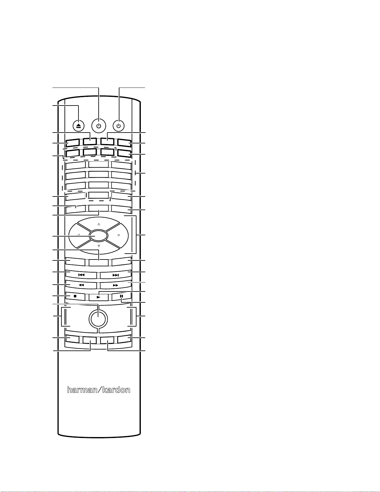
Remote Control Functions
Power Button
Eject Button
EJECT POWER TV
Radio Input Button
RADIO
Disc Input Button
HDMI 1 – 3
Input Buttons
Repeat Button
Home Button
Surround Button
OK Button
Top Menu Button
Clear/Exit Button
Previous/Step
Button
Search/Slow
Reverse Button
Stop Button
Mute Button
Volume Up/Down
Buttons
Program (Red)
Button
Bookmark
(Green) Button
DISC
HDMI2
HDMI1
1
4
7
REPEAT
HOME
CLEAR/EXIT
+ +
VOLUME
PROGRAM
BOOKMARK
2
5
8
0
SURROUND
OK
TOP MENU
MUTE
THUMBNAIL
BRIDGE
HDMI3
COMPONENT
3
6
9
DISPLAY
OPTIONS
POP-UP
CHANNEL
––
AUX
ZOOM
TV Power Button
Bridge Input Button
Aux Input Button
Component
Input Button
Numeric Buttons
Display Button
Options Button
Cursor Controls
Pop-Up Button
Next/Step Button
Search/Slow
Forward Button
Play Button
Pause Button
Channel Up/
Down Buttons
Zoom (Blue)
Button
Thumbnail
(Yellow) Button
Power button: Pressing this button toggles the BDS receiver between the On and
Standby modes.
TV Power button: After you program the remote control, pressing this button turns
the TV’s power on and off. See Programming the Remote, on page 14.
Eject button: Press this button to eject a disc from the BDS receiver’s built-in disc
player. Before pressing this button, make sure no objects are blocking the disc slot
opening.
Radio Input button: Pressing this button selects the BDS receiver’s built-in FM
radio as the system’s active audio source. Pressing this button also puts the remote
control into the control mode for the radio. See Using the Radio, on page 22, for
details. NOTE: Pressing this button when the BDS receiver is in the Standby mode
will switch it on.
Bridge Input button: P ressing this button selects an iPod devi ce inserted
in a co nn ec ted The Bridge IIIP dock (available separately) as the system’s active
audio source. Pressing this button also puts the remote control into the control
mode for the iPod device. See Listening to Your iPod/iPhone Device, on page 22, for
details. NOTE: Pressing this button when the BDS receiver is in the Standby mode
will switch it on.
Disc Input button: Pressing this button selects the BDS receiver’s built-in disc
player as your entertainment system’s active audio and video source and plays a
disc that has been inserted into the player. Pressing this button also puts the remote
control into the disc player control mode. See Using the Disc Player, on page 20, for
details. NOTE: Pressing this button when the BDS receiver is in the Standby mode
will switch it on.
Aux Input button: Pressing this button selects the receiver’s active rear-panel
audio input as the system’s active audio source. Repeatedly pressing the button
cycles through all of the rear-panel audio inputs. See Listening to Audio Sources,
on page 23, for details.
Pressing this button also places the remote into the auxiliary-component control
mode, enabling the remote to use any pre-programmed and/or learned functions.
See Listening to Audio Sources, on page 23, for details. NOTE: Pressing this button
when the BDS receiver is in the Standby mode will switch it on.
HDMI 1-3 Input buttons: Pressing these buttons selects the device connected to
the corresponding HDMI input as the active audio and video source. NOTE: Pressing
any of these buttons when the BDS receiver is in the Standby mode will switch it on.
Component Input button: Pressing this button selects the device connected to the
Component Video Input connector as the active video source. NOTE: Pressing this
button when the BDS receiver is in the Standby mode will switch it on.
Numeric buttons: Use these buttons to enter numbers for various items.
Repeat button: When the BDS receiver is playing a Blu-ray Disc recording or DVD,
pressing this button cycles through the following repeat modes: Chapter, Title, All,
Off. When the BDS receiver is playing a CD or listening to media stored on an iPod
or USB device, this button cycles through the following repeat modes: Track, All, Off.
Display button: When you are playing Blu-ray Disc and DVD recordings, pressing
this button activates a bar display containing information about the currentlyplaying disc or program. The button does not function when the BDS receiver is
playing material from an iPod device, a USB device, an auxiliary source or the radio.
Home button: Pressing this button returns the on-screen display to the Home
screen from whatever screen is active when the button is pressed.
Options button: Pressing this button displays any available options for the item
that is active at the time the button is pressed. When listening to an Aux source,
pressing the Options button lets you adjust the audio delay to eliminate “lip sync”
errors between the sound and picture when watching video programs with sound
playing through one of the receiver’s rear-panel audio inputs. See Listening to Audio
Sources, on page 23, for details.
Surround button: Pressing this button cycles through all of the surround-sound
modes that are available for the active program. Each press of the Surround button
will change to the next mode in line. A pop-up display will appear, showing the
modes as you cycle through them. NOTE: Not all surround modes will be available
for all programs. See Surround-Sound Modes, on page 20, for more information.
8
Page 10

BDS 270/BDS 570
harman/kardon
BDS 270 + 570 Service Manual
Page 10 of 90
Remote Control Functions
OK button: Press this button to select the highlighted item on the on-screen menu.
Cursor controls: Use these buttons to navigate through items on the on-screen
menu.
Top Menu button: Displays the top menu of the Blu-ray Disc recording or DVD that
is playing. NOTE: This feature is disc-dependent. Not all DVDs have top menus. If
the DVD has no top menu, pressing the Top Menu button may display the disc menu,
depending on how the disc’s menu system was authored. See Using the Disc Player,
on page 20, for details.
Clear/Exit button: Pressing this button exits the current on-screen menu and
displays the previous screen; it also clears incorrect entries made when entering
numbers with the Numeric buttons.
Pop-Up button: Pressing this button while playing a Blu-ray Disc recording or DVD
displays its disc menu. NOTE: This feature is disc-dependent. Not all DVDs have
pop-up menus. If a DVD has no pop-up menu, pressing the Pop-Up button may
display the disc menu, depending on how the disc’s menu system was authored.
Previous/Step button: Press this button once to skip to the beginning of a track
or, when viewing photos, to the previous photo. Press the button twice to skip to
the beginning of the previous track. Press the button repeatedly to go back through
the previous chapters or tracks. When video content is playing on Blu-ray Disc
recordings and DVDs, press the Pause button first; afterwards, each subsequent
press of the Previous/Step button reverses the video one frame.
Next/Step button: Press this button once to skip to the beginning of the next track
or, when viewing photos, to the next photo. Press the button repeatedly to advance
through the next chapters or tracks. When video content is playing, press the Pause
button first; afterwards, each subsequent press of the Next/Step button advances
the video one frame.
Search/Slow Reverse button: Press this button to reverse through a disc track.
For Blu-ray Disc recordings and DVDs, each press cycles through 2x, 4x, 8x, 16x
and 32x reverse speed. Pressing the button while a Blu-ray Disc recording or DVD is
paused will reverse through the chapter in slow motion. Each press cycles through
1/2, 1/4, 1/8 and 1/16 normal speed.
Search/Slow Forward button: Press this button to fast-forward through the current
disc track. For Blu-ray Disc recordings and DVDs, each press cycles through 2x, 4x,
8x, 16x and 32x normal speed. Pressing the button while a Blu-ray Disc recording
or DVD is paused will play through the chapter in slow motion. Each press cycles
through 1/2, 1/4, 1/8 and 1/16 normal speed.
Stop button: Press this button to stop playback at the current point. (Pressing the
Play button will resume playback from this point.) Press the Stop button twice to
stop playback fully. NOTE: Some settings and functions will be available only when
the player is fully stopped.
Play button: Press this button to play a disc that has been loaded into the player’s
disc drawer or a music file that has been highlighted on the on-screen menu.
Pressing this button when viewing photos begins a slide show of all photos in the
current folder.
Mute button: Press this button to mute the sound from the BDS receiver’s speaker
outputs. Press the button again to un-mute the sound. NOTE: The Mute button does
not mute the HDMI audio outputs.
Pause button: Press this button to pause a disc or music file that is playing. Pressing
the button while a Blu-ray Disc recording or DVD is playing will freeze-frame on the
current video frame. Pressing the button while the disc is paused will resume play.
Pressing this button while viewing photos freezes the current photo on the screen.
Volume +/– buttons: Press these buttons to increase or decrease the volume of the
BDS receiver’s speaker outputs. NOTE: The Volume +/– buttons do not change the
volume of the HDMI audio outputs.
IMPORTANT: Do not turn the Volume buttons up to or past the point where the
audio from the speakers becomes distorted. Doing so can damage the speakers.
Channel +/– buttons: When Radio is the source selected on the remote control, the
Channel +/– buttons select the next higher or lower preset station.
Program (Red) button: Press this button to create a programmed playback list for
the currently-playing disc. See Programmed Play, on page 21, for more information.
Zoom (Blue) button: Press the Zoom button to zoom in on or recede from a video
image or slide. Use the Navigation buttons to zoom in on different sections of the
image. NOTE: This function is disc-dependent for Blu-ray Disc recordings and DVDs.
Not all discs can be zoomed in on.
Bookmark (Green) button: Press this button to activate the Bookmark function.
See Bookmark Function, on page 21, for more information.
Thumbnail (Yellow) button: Press this button while playing a photo slide show to
display thumbnail images of all photos in the slide show.
Red, Green, Yellow and Blue buttons: When the BDS receiver is playing a
Blu-ray Disc recording, these buttons can activate features and menus that may
vary from disc to disc. Refer to the menu instructions for each particular disc for
more information. NOTE: These Blu-ray Disc functions may override the Bookmark,
Thumbnail, Program and Zoom functions.
9
Page 11
ConnectionsBDS 270/BDS 570
harman/kardon
BDS 270 + 570 Service Manual
Page 11 of 90
Connections
CAUTION: Before making any connections to the BDS receiver, ensure that the
receiver’s AC cord is unplugged from the receiver and the AC outlet. Making
speaker connections with the receiver plugged in and turned on could damage
the speakers.
Speakers and receivers/amplifiers have corresponding (+) and (–) connection terminals.
Most speakers use red to denote the (+) terminal and black for the (–) terminal.
• The BDS receiver uses white to denote the left channel (+) terminal and red for the
right channel (+) terminal. Black is used to denote the (–) terminal of both channels.
• The BDS receiver uses the following colors to denote the (+) terminals of the various
channels:
Front Left (+): White Surround Left (+): Blue
Front Right (+): Red Surround Right (+): Gray
Center (+): Green
Black is used to denote the (–) terminals of all channels on the BDS receiver.
Be sure to connect each speaker identically: (+) on the speaker to (+) on the receiver
or amplifier, and (–) on the speaker to (–) on the receiver or amplifier. Miswiring one or
more speakers results in thin sound, weak bass and a poor stereo image.
CAUTION: Make sure the (+) and (–) bare wires do not touch each other or the
other terminal. Touching wires can cause a short circuit that can damage your
receiver or amplifier.
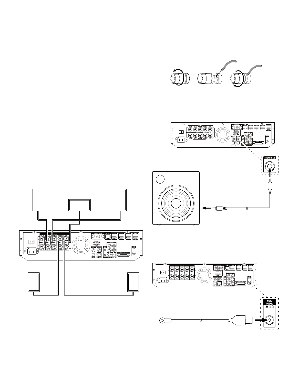
Connecting the Speakers
Front Right
Speaker
Center
Speaker*
Front Left
Speaker
Connecting the Receiver Terminals
A. Unscrew Cap B. Insert Bare Wire C. Tighten Cap
Connecting a Powered Subwoofer
Use a mono RCA audio cable to connect the BDS receiver’s Subwoofer Output connector
to your powered subwoofer; consult your subwoofer's user manual for information
about making connections to your subwoofer.
Powered
Subwoofer
Mono RCA
Audio Cable
(not supplied)
Surround Right
Speaker*
* Used only with BDS 570 receiver
10
Surround Left
Speaker*
IMPORTANT: Do not plug the subwoofer’s AC power cord into an AC outlet at this time.
Connecting the FM Antenna
Connect the supplied antenna to the FM Antenna connector, as shown in the illustration
below. Fully extend the antenna wire and move it to different positions until you get the
best reception of your favorite stations.
FM Antenna
Page 12
BDS 270/BDS 570
harman/kardon
BDS 270 + 570 Service Manual
Page 12 of 90
Connections
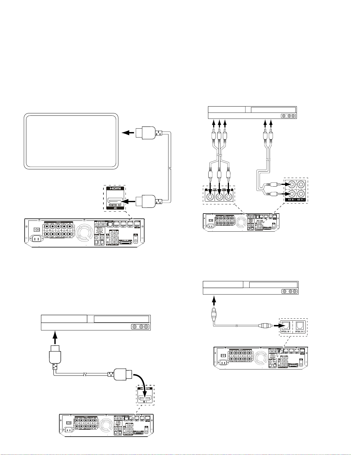
Connecting a TV or Video Display
Use the supplied HDMI cable to connect the BDS receiver’s HDMI output to your TV/video
display’s HDMI input. The BDS receiver is HDMI version 1.4a with 3-D and 30/36-bit
Deep Color.
NOTE: If you have devices (such as an Internet modem) already connected directly
to your TV, you can feed their sound to the BDS receiver via the HDMI Monitor Out
connector’s Audio Return Channel, and they will not require additional connections to
the receiver.
TV
Connecting Your Component Video Source Device
If you have a video source device that has a component video connector (and does not
have an HDMI connector), using the component video connector will provide superior
video performance. You will also need to make an audio connection from the device to
the receiver’s Aux In 1 connectors.
Component Video-Equipped
Source Device
To Component
Video Outputs
Component Video
Cable (not supplied)
To Analog
Audio Outputs
Stereo Audio
Cable (not supplied)
NOTE: The HDMI connection will deliver both video and audio to your TV or video display.
We suggest disabling your TV or video display’s audio system to take full advantage of
your BDS receiver's superior audio reproduction.
Connecting Your HDMI Source Devices
If you have any source devices with HDMI connectors, using them will provide the
best possible video and audio performance quality. Since the HDMI cable carries both
digital video and digital audio signals, you do not have to make any additional audio
connections for devices you connect via an HDMI cable.
HDMI-Equipped
Source Device
To HDMI
Output
HDMI Cable
(not supplied)
Connecting Your Optical Digital Audio Source Devices
If up to two of your non-HDMI source devices have optical digital outputs, connect them
to the receiver’s optical digital audio connectors. NOTE: Make only one type of digital
connection (HDMI, optical or coaxial) from each device.
Optical-Equipped
Source Device
To Optical Digital
Audio Output
Optical Digital Audio
Cable (not supplied)
11
Page 13
BDS 270/BDS 570
harman/kardon
BDS 270 + 570 Service Manual
Page 13 of 90
Connections
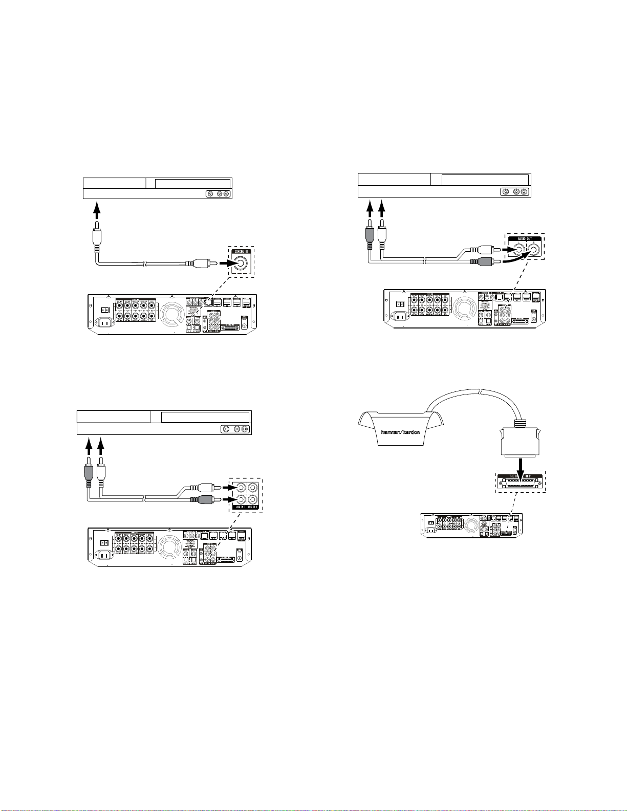
Connecting Your Coaxial Digital Audio Source Device
If one of your non-HDMI source devices has a coaxial digital output, connect it to the
receiver’s Coaxial Digital Input connector. NOTE: Make only one type of digital connection
(HDMI, optical or coaxial) from each device.
Coaxial-Equipped
Source Device
To Coaxial Digital
Audio Output
Coaxial Digital Audio
Cable (not supplied)
Connecting Your Analog Audio Source Devices
Use the receiver’s Aux In connectors for up to two source devices that don’t have HDMI
or digital audio connectors.
Analog
Source Device
Connecting Your Analog Recorder
Connect an analog audio recorder’s inputs to the receiver’s Analog Audio Output
connectors. You can record any analog audio input signal.
Analog
Recorder
To Record
Inputs
Stereo Audio Cable
(not supplied)
Connect an Optional The Bridge IIIP
Connect an optional The Bridge IIIP to the receiver’s The Bridge IIIP connector. Insert the
plug until it snaps into place in the connector. IMPORTANT: Connect The Bridge IIIP
only with the receiver’s power turned OFF.
The Bridge IIIP
To Stereo Analog
Audio Output
Stereo Audio Cable
(not supplied)
12
Page 14
PL0004-01001
BDS 270/BDS 570
harman/kardon
BDS 270 + 570 Service Manual
Page 14 of 90
Connections
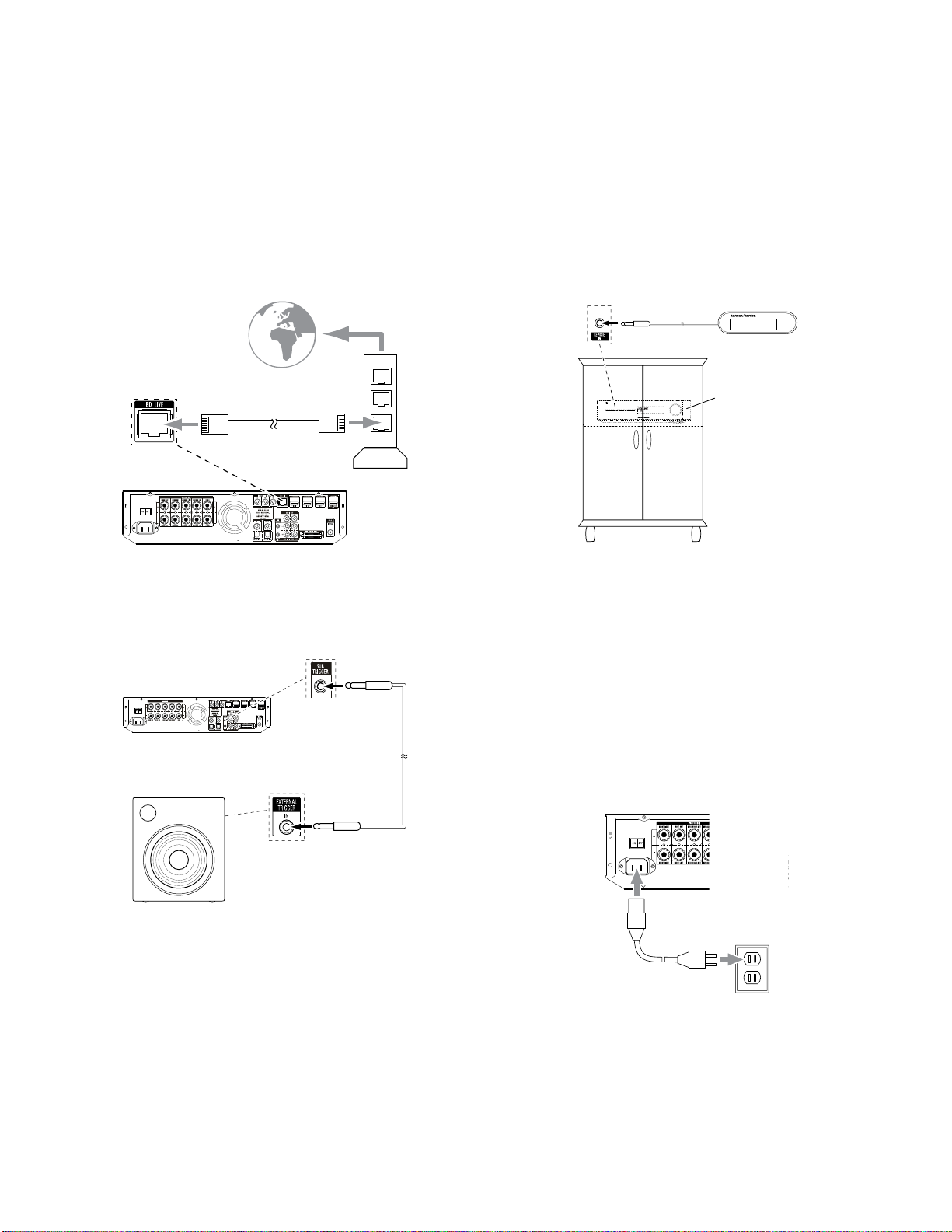
Connecting to a Local Area Network (LAN)
Use a Cat. 5/5E network cable (not supplied) to connect the BDS receiver’s BD-Live
connector directly to a network router, a network switch, a network modem or an Ethernet
network wall jack that has Internet access.
NOTE: The BDS receiver can not access content on other networked devices. The Network
connection enables only the receiver’s BD-Live features. See BD-Live Interactivity, on page
21, for details.
To
Internet
Cat. 5/5E
Network
Modem
Connect the Subwoofer Trigger Output
If your system has equipment that can be controlled by a DC trigger signal, connect it
to the receiver’s Subwoofer Trigger connector with a mono 1/8-inch (3.5mm) mini-plug
interconnect cable (not supplied). The receiver will supply a 12V DC (100mA) trigger
signal at this connection whenever it is powered on.
Device with
Trigger In Connector
Mono 1/8-Inch
(3.5mm)
Mini-Plug
Interconnect
(not supplied)
Connect the Remote IR Input
The BDS receiver is equipped with a Remote IR Input connector that lets you remotely
control the receiver when you place it inside a cabinet or in a location that is out of the
line of sight of the remote control. Connect an external IR receiver, such as the optional
Harman Kardon HE 1000, to the receiver's Remote IR Input connector.
BDS Receiver
Remote IR
Input Connector
External IR
Receiver
BDS Receiver Installed
Inside of Cabinet
Connecting the AC Power
The BDS receiver comes with a detachable AC power cord. This type of cord makes it
easier for you to install and connect all other system wiring to the receiver’s rear panel.
The subwoofer has a non-detachable power cord.
NOTES:
• The power requirement for the BDS receiver is 110V – 240V AC, 50/60Hz, 130W
(BDS 570 receiver) or 90W (BDS 270 receiver). Connecting to a power source other
than the ones listed may damage the receiver or cause abnormal operation.
• Before connecting the AC power cord to a wall outlet, confirm that you have
correctly made all of the speaker connections, video connections and audiocomponent connections.
Connect the female end of the receiver’s detachable power cord to the receiver’s AC
Power connector. Plug the other end into a working, unswitched AC outlet.
Receiver
Set the receiver’s Main Power switch to the “On” position. The receiver’s Power indicator
will turn amber, indicating that the receiver is in the Standby mode.
13
Page 15
CLEAR/EXIT
DISPLAY
BDS 270/BDS 570
harman/kardon
BDS 270 + 570 Service Manual
Page 15 of 90
Preparing the Remote Control
Preparing the Remote Control
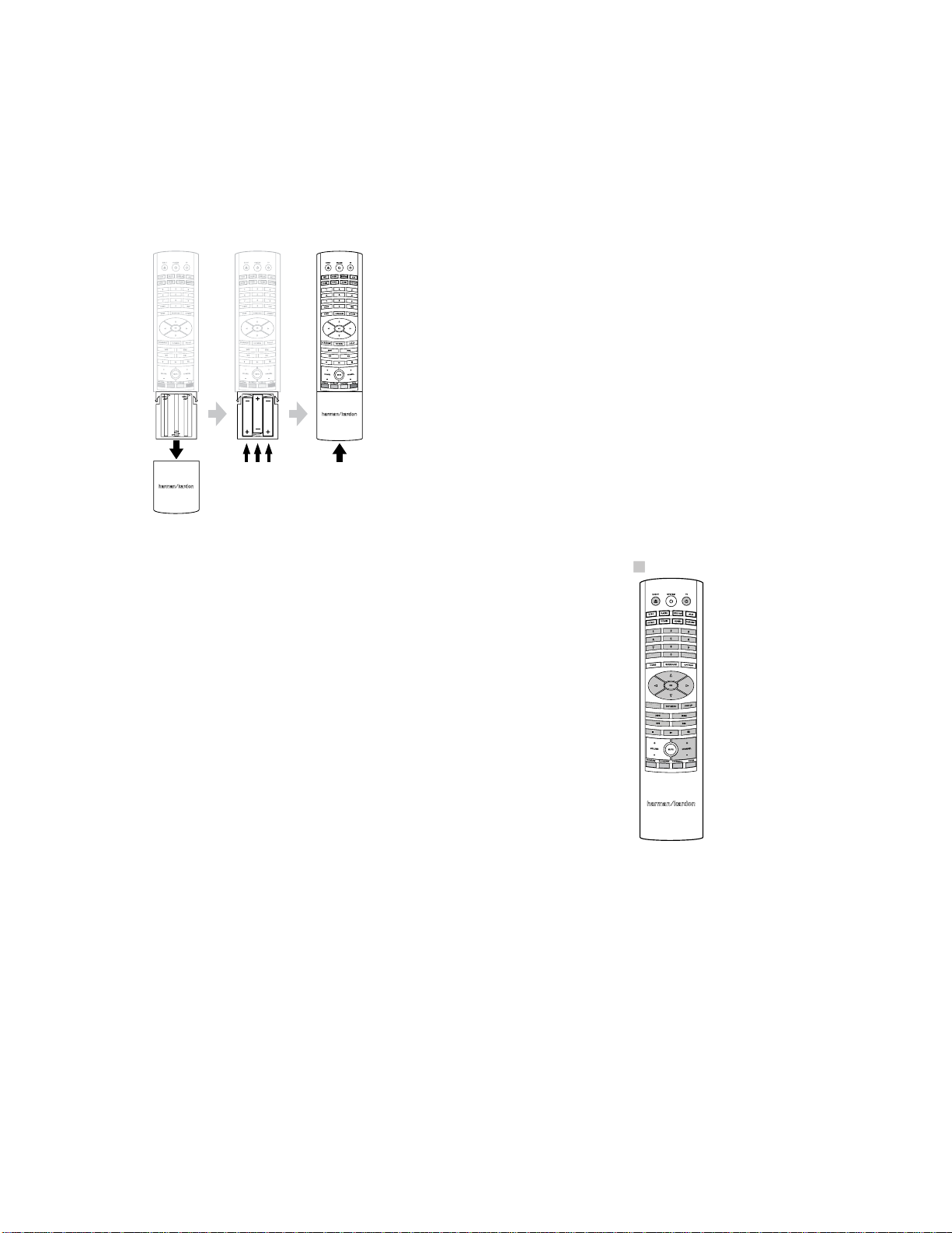
Installing the Batteries
Your receiver’s remote control uses three AAA batteries (supplied). Insert the batteries as
shown in the illustration, making sure to observe the correct polarity.
Using the Remote
When using the remote, remember to aim it toward the receiver’s front panel. Make
sure that no objects, such as furniture, block the remote’s view of the receiver. Bright
lights, fluorescent lights, and plasma-video displays may interfere with the function of
the remote.
• The remote has a range of about 20 feet (6.1m), depending on the lighting conditions.
• You can use the remote at an angle of up to 30° to either side of the BDS receiver.
If the remote seems to operate intermittently, or if pressing a button on the remote does
not cause one of the Input buttons to light up, make sure that the batteries are inserted
correctly. If the remote still operates intermittently, replace all three batteries with new
ones.
Programming the Remote
In addition to controlling the BDS receiver, you can program the remote to control one
auxiliary (Aux) component. The remote is also capable of learning codes directly from
other remotes. This ability allows you to combine learned commands with programmed
codes, making the remote capable of controlling more than one Aux component. Typical
Aux components would be your TV, a satellite receiver or a cable receiver.
The remote will control the Aux component(s) only when the Aux source button has
been pressed. Pressing any other source button will put the remote back into the BDS
receiver control mode.
To program the remote to control an Aux component:
1. Look up the codes for the component type (e.g, TV or cable TV box) and the brand
name of your source in the Aux Component Remote-Control Code List, on page 27.
2. Turn your auxiliary component on.
3. Press and hold the Aux button for three seconds as it turns red, goes dark and turns
red again. Then release the button.
NOTE: The remote will remain in the programming mode for 20 seconds. You must
perform Step 4 within 20 seconds.
4. Aim the remote toward the component you just turned on and enter a code number
from Step 1, above. If the component turns off, check that its own remote-control
buttons control the component as expected. If they do, press the Aux button again
to save the code. The button will flash three times, and the remote will exit the
programming mode.
5. If any of the buttons do not work as expected, or if the component does not turn off
when you enter the code number, repeat Step 4 with another code number from the
list for that manufacturer.
6. If you run out of codes for a component, you can search through all of the codes in
the remote’s library for that component type.
a) Press and hold the Aux button for three seconds. The button will turn red, go
dark and turn red again. Then release the button.
b) For a conventional US TV, enter “0999”; for a conventional EU TV, enter “1999”;
for an HDTV, enter “2999”; for a US cable box, enter “3999”; for an EU cable
box, enter “4999”; for a US satellite tuner, enter “5999”; for an EU satellite
tuner, enter “6999.”
c) Aim the remote control toward the component and press the remote’s Cursor
Up button. Each press of the button sends the “Power” signal for one setup
code number. Holding down the Cursor Up button quickly scans through all of
the setup code numbers.
d) Release the Cursor Up button as soon as the component turns off. If you pass
the correct setup code number, you can return to it by pressing the Cursor
Down button, one setup code number at a time, until the component turns back
on.
e) Check that the other remote-control buttons control the component as
expected. If they do, press the Aux button again to save the code. The button
will flash three times, and the remote will exit the programming mode.
f) If the remote does not operate as expected, repeat Steps c – e. Note that some
components may not respond to all of the above commands and may support
only some of the commands listed.
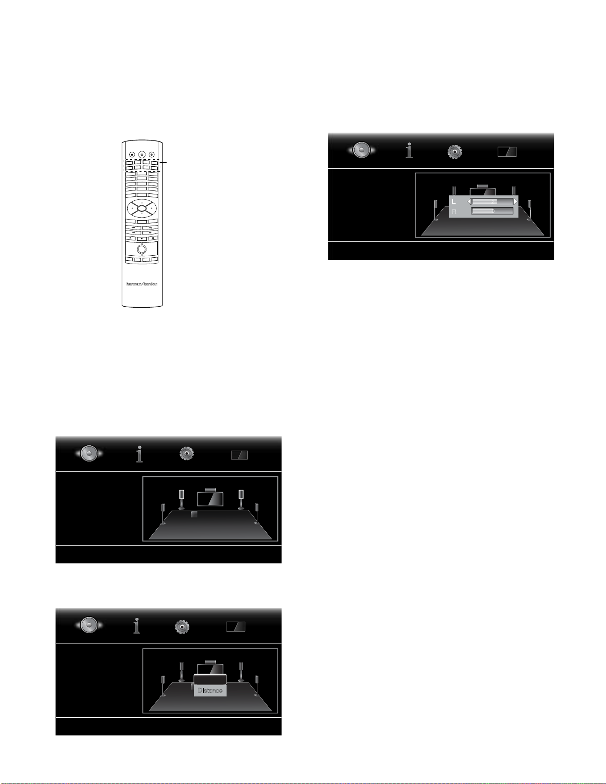
To teach individual button codes to the remote:
You can teach codes from other component remotes onto the BDS receiver remote
buttons shown shaded in the following illustration:
= Learning Capable
DISPLAY
REPEAT
CLEAR/EXIT
1. Place the BDS receiver remote and the remote from which you want it to learn
codes head-to-head about 1 inch (2.5cm) apart, with their IR transmitter windows
facing each other.
2. Press and hold the Options button on the BDS receiver remote for more than three
seconds. The remote’s Aux button will light up.
3. Press the button on the BDS receiver remote to which you want to teach the
command. The Learn mode will remain active for 20 seconds after the button is
pushed.
4. Press the button on the other remote that you want to “teach” to the BDS receiver
remote. When the IR code has been received and stored, the Aux button’s LED will
flash three times, and the BDS receiver remote will remain in the learning mode,
ready to learn another code. If no IR code is received within 20 seconds, the Aux
LED will flash rapidly several times, and the remote will exit the learning mode. To
resume programming, return to Step 2.
5. Repeat Step 3 and Step 4 for each command you want to teach the BDS receiver
remote. NOTE: If the Aux button’s LED goes out at any time, you will need to begin
again from Step 2.
14
Page 16

BDS 270/BDS 570
harman/kardon
BDS 270 + 570 Service Manual
Page 16 of 90
Preparing the Remote Control and
Setting Up the Receiver
Programming Remote Control “Punch-Through” Commands
After programming the remote to control an auxiliary (Aux) component, you can also
program it so it will control the Aux component’s channel up/down and transport
functions (Play, Pause, etc.) even when the remote is not in the Aux-control mode. For
example, if the remote is programmed to operate your TV in the Aux control mode, you
can also have the TV’s channel +/– functions “punch through” and operate even when
the remote is in the Disc, Radio or iPod control modes.
1. Press and hold the Input button for the main device the remote will be operating. The
button will light up, go dark and then light up again. Release the button.
2. Select the type of punch-through programming.
a) For “punch-through” channel control, press the Channel Up button.
b) For “punch-through” transport control, press the Play button.
3. Press the Aux button. The original Input button will flash to confirm.
You can repeat Step 1 – Step 3 for any of the remote’s Input buttons (Aux, Radio, etc.).
NOTE: “Punch-through” channel and transport commands will override the existing
commands for those buttons in the source modes you program.
To undo “punch-through” programming, follow the same steps as above, but press the
same Input button in Step 1 and Step 3.
Using the Remote After it is Programmed
Pressing the remote’s Aux Input button will put the remote into the auxiliary-control
mode, and it will control the auxiliary component(s) via the codes you have programmed
into it.
To switch the remote back to the BDS receiver-control mode from the auxiliary-control
mode, press any of the other Input buttons or the Home button.
Setting Up the Receiver
NOTE: The menu screens shown in this manual are for illustrative purposes and may
differ somewhat from the actual displays.
To set up your BDS receiver, you will use the remote to navigate through all of the onscreen menus and to make selections from them.
• Use the Cursor Up/Down buttons to navigate through the menu list. When an item is
highlighted, a white border will appear around it.
• To select a highlighted item, press the OK button. The screen will change depending
on your selection.
• To return to the previous screen, press the Exit button.
Setup Wizard
When you turn your BDS receiver on for the first time, the on-screen menu will display
the Setup Wizard.
Setup Wizard Page: 1/5
Welcome to the Harman Kardon BDS Setup
Wizard.
Some simple information is needed to ensure
you get the best experience from your product.
You can adjust these settings later in addition
top making changes to more advanced settings
by selecting ‘Settings’ from the Home Menu.
Before you can use your BDS receiver, you need to set the language and make a few
basic settings so that its video output will work properly with your TV. Press the OK
button and the Wizard’s language screen will appear.
Setup Wizard
Please select which language you would like
the BDS menus to appear in.
Previous
OK
Page: 2/5
English
Español
Français
Deutsch
Italiano
Next
After setting the language you want the on-screen menus to appear in, press the OK
button and the Wizard’s TV-resolution screen will appear.
Setup Wizard
Please select the highest resolution that your TV
supports. If you are unsure, select ‘Auto’.
Upon making a selection the screen will be
changed to the chosen resolution. You will be
presented with the option to continue with the new
resolution or ‘Cancel’ to return to the previous
resolution. If the screen remains blank, please wait
15 seconds without pressing anything and the
system will automatically return to the previous
resolution.
Previous
480p/576p
OK
Page: 3/5
Auto
720p
1080i
1080p
Next
After selecting your TV’s highest resolution, press the OK button, and the Wizard’s
aspect-ratio screen will appear. Note: If you are unsure of your display’s highest
resolution, select “Auto” and the BDS receiver will select the optimal resolution for you.
Setup Wizard
Please select the best aspect ratio that fits your TV.
Please see the owners manual for additional
explanation.
Previous
16:9 Full
16:9 Normal
4:3 Pan & Scan
4:3 Letterbox
OK
Page: 4/5
Next
After selecting the aspect ratio that best fits your TV, press the OK button to save your
OK
Next
setting, then press it again to exit the Setup Wizard.
15
Page 17
BDS 270/BDS 570
harman/kardon
BDS 270 + 570 Service Manual
Page 17 of 90
Setting Up the Receiver
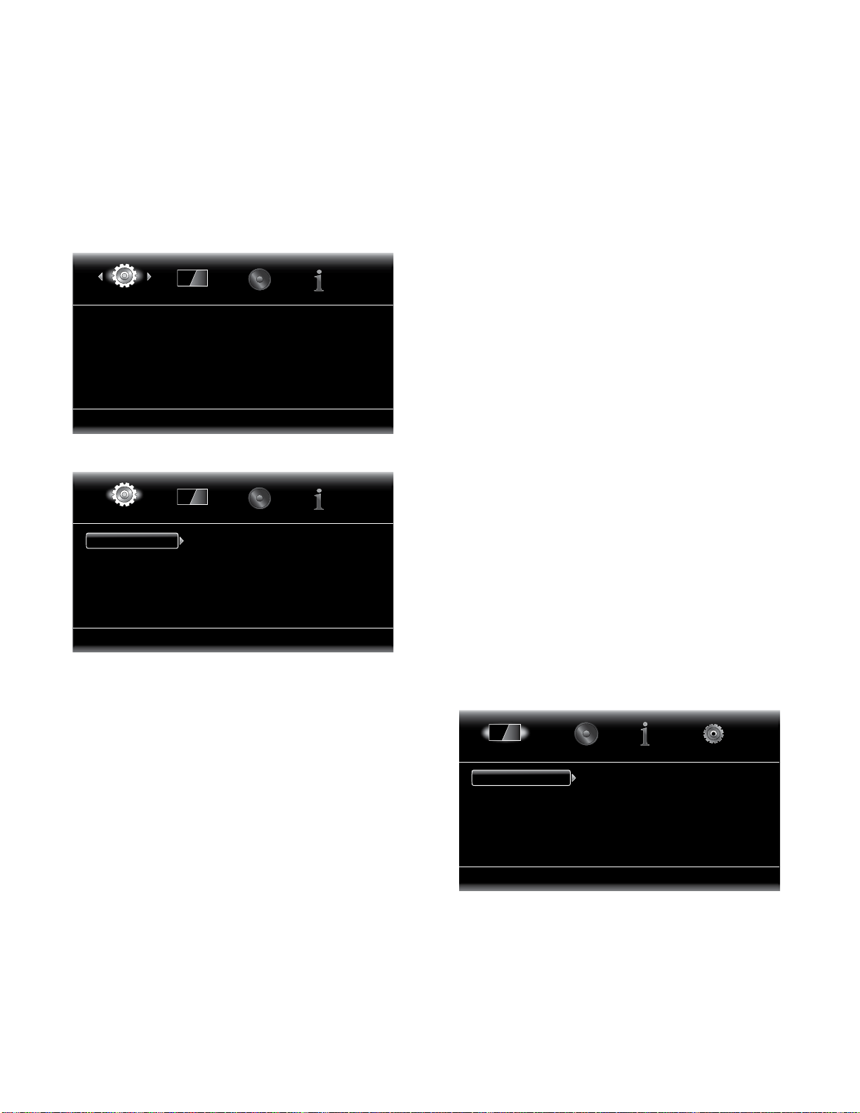
Settings Menus
Selecting “Settings” on the Home Menu screen displays the receiver’s settings menus,
which allow you to configure the receiver’s various functions. Use the remote’s Cursor
Left/Right buttons to change from one menu to another, use the Cursor Up/Down buttons
to navigate through the lists that appear on the various screens, and use the OK button
to select highlighted items. Press the Exit button at any time to return to the previous
screen.
General Settings
System
Language
Playback
Parental Control
Network
Select to adjust general settings
General Settings
General Settings
System
Language
Playback
Parental Control
Network
Select to adjust system settings
Front Panel Brightness
Screen Saver
Auto Power Off
One Touch Play
One Touch Standby
System: The System option allows you to set the following system features:
Front Panel Brightness: This option sets the brightness of the BDS receiver’s information
display.
Screen Saver: To prevent image burn-in, we recommended activating the Screen Saver
when using the BDS receiver with a CRT or plasma TV.
Auto Power Off: This option sets the amount of time the BDS receiver remains on while
idle until it automatically enters the Standby mode.
One Touch Play: When this option is set to “On,” pressing the Play button on the BDS
receiver when a Blu-ray Disc or DVD is inserted will automatically turn a connected TV
on and switch it to the input connector where the BDS receiver is connected. NOTE: The
TV must support HDMI CEC (Consumer Electronics Control).
One Touch Standby: When this option is set to “On,” putting a connected TV into the
standby mode will automatically place the BDS receiver into the standby mode. NOTE:
The TV must support HDMI CEC (Consumer Electronics Control).
System Upgrade: Select this option when you want to install a firmware upgrade for your
BDS receiver that you’ve downloaded from a Harman Kardon Web site or other Harman
Kardon source.
Setup Wizard: This option activates the receiver’s Setup Wizard (see Setup Wizard, on
page 15).
BD-Live Storage: This option lets you set up how the BDS receiver will handle stored BD-Live
content. You can choose to store the content either in the receiver’s internal memory or
on a USB memory device via the receiver’s USB port. See BD-Live Interactivity, on page
21, for details.
100%
Off
Off
On
On
Restore Defaults: This option restores the receiver to its factory-default setting values.
Note: This procedure deletes all preset FM stations and restores the parental-control
password back to the factory default of 0000.
Language: This setting lets you set the language for the disc player and the disc menus,
the preferred audio language and the preferred subtitle language.
NOTE: If the selected language is not available on the particular disc being played, use
the disc’s menu to set the language from those available on the disc.
Playback: The Playback option allows you to set the following disc playback features:
Show Angle Icon: This option lets you select whether or not the angle icon will
automatically be displayed when a disc with multiple camera angles is played.
Auto Play: This option lets you select whether discs will automatically begin playing
when they are inserted into the BDS receiver’s disc player.
Show PIP Icon: This option lets you select whether or not the picture-in-picture (PIP) icon
will automatically be displayed when a Blu-ray Disc recording with PIP content is played.
Secondary Audio Icon: This option lets you select whether or not the Secondary Audio
Icon will automatically be displayed when a Blu-ray Disc recording with secondary audio
content is played.
Disc Resume: This option lets you select whether or not a disc that has been ejected
while playing will resume play from that location when it is re-inserted into the receiver’s
disc player.
®
DivX
VOD DRM: This option displays your receiver’s DivX registration information.
Parental Control: This option lets you set the receiver’s parental-control password and
the level of parental control you want active. NOTE: The default password is 0000.
Network: This option allows you to set the following network features:
Information: This displays your network’s IP, Subnet Mask, Gateway and DNS addresses.
Test Connection: This option tests for a proper network connection to the BDS receiver.
IP Configuration: This option lets you enter your network settings, either automatically
or manually. Unless your network administrator instructs you otherwise, you should use
the Auto option.
BD-Live Connection: This option lets you set the receiver’s BD-Live connection
preferences. “Always Allow” allows downloading of BD-Live content whenever a disc
with BD-Live content is played. “Limit” allows downloading only if the disc is officially
BD-Live certified. “Prohibited” does not allow any BD-Live access.
Proxy Setting: “Enabled” allows you to select and set the proxy host and proxy port if
your network requires a proxy setting. “Disabled” bypasses any Proxy Host and Proxy
Port settings and prevents their selection. This option is for advanced users only and in
most cases should be left set to “Disabled.”
Display Settings
Display Settings
TV
Video Processing
Select to adjust display settings
Aspect Ratio
Resolution
Color Space
Film Mode
HDMI Deep Color
16:9 Full
Auto
RGB
Off
Off
TV: This option allows you to set the following display parameters:
Aspect Ratio: This option lets you select how you want 4:3 programs displayed on a
16:9 TV, or 16:9 programs displayed on a 4:3 TV. “16:9 Full” stretches 4:3 material
to fill a 16:9 TV screen. “16:9 Normal” displays 4:3 material on a 16:9 TV with black
boxes on either side of the picture, preserving the program’s original visual composition
without distortion. “4:3 Pan & Scan” zooms in on widescreen material to fill a 4:3 screen.
“4:3 Letterbox” displays 16:9 material with black bars above and below the picture,
preserving the program’s original visual composition without distortion.
16
Page 18
BDS 270/BDS 570
harman/kardon
BDS 270 + 570 Service Manual
Page 18 of 90
Setting Up the Receiver
Resolution: This option lets you select your TV’s highest resolution. “Auto” automatically
selects the best resolution for your TV.
Color Space: This option lets you match the BDS receiver’s video output to the color
space of the connected TV or video display. Check the documentation for your TV or
video display to determine the color space it uses.
Film Mode: If your TV can handle a 1080p 24Hz signal (if it has 1080 resolution and
a video-refresh rate that is a whole-number multiple of 24), set Film Mode to “On” to
get maximum resolution from Blu-ray Disc content mastered at 24 frames per second.
If your display cannot handle a 1080p/24Hz signal, set this option to “Off,” and the
BDS receiver will upconvert 24-frame-per-second film material to the standard video
30Hz refresh rate.
HDMI Deep Color: This option allows you to adjust the resolution of color output to your
TV. If your TV accepts Deep Color, this option allows your TV to display an enhanced
color palette.
• On: The BDS receiver outputs 36-bit Deep Color if your TV supports it. If your TV does
not, the receiver will output 30-bit color.
• Off: The BDS receiver does not output Deep Color (color resolution remains at 24 bits).
TV Standard: This option allows you to set the BDS receiver to match your area’s
television standard. Select NTSC for the USA or PAL for Europe. Select “Auto” to allow
the receiver to match the standard of the connected TV automatically.
HDMI 3D: This option lets you determine how the BDS receiver will handle HDMI 3-D
content. If you have connected the receiver to a 3-D capable TV, select “Auto” to allow
the receiver to play 3-D content in 3-D automatically. If you have connected the receiver
to a TV that is not 3-D capable, select “Off” to play 3-D content in 2-D.
Video Processing: This option allows you to set the BDS receiver’s internal video
processing.
Video Mode: This setting lets you select a preset video-processing option to optimize
the picture for the current program by adjusting the brightness, contrast, color and
sharpness:
• Standard: Neutral control settings.
• Vivid: For video games.
• Cinema: For movies and many television broadcasts.
• Custom: This option lets you adjust the picture settings manually. The Brightness,
Saturation (color saturation), Hue, Contrast, Sharpness and CTI settings appear
as sliders. The default setting for each adjustment is 0. Use the Cursor Left/Right
buttons to change each setting’s value.
Audio Settings
Dynamic Range Control: This setting makes the loud and quiet parts of a movie or music
closer to the same volume (a process known as compression). Compression lets you
turn up the volume so you can hear the quiet parts without the loud parts disturbing
other people. NOTE: This feature works only with Dolby Digital programs that have been
specially encoded. Three settings are available:
• Off: Never applies compression. Use this setting when the volume may be as loud
as you desire.
• On: Always applies compression. Use this setting when you want the volume to be
as quiet as possible without making it difficult to hear spoken dialogue.
• Auto: Applies compression based on information encoded in the Dolby Digital
bitstream. The receiver will selectively apply compression only during the most
dynamic parts of the soundtrack.
Lip Sync: This setting lets you resynchronize the audio and video signals from a
Blu-ray Disc recording or DVD to eliminate a “lip sync” problem. Lip-sync issues can
occur when the video portion of a signal undergoes additional processing in the video
display. Use the Left/Right Cursor buttons to delay the audio by up to 250ms until it is
synchronized with the video. Press the Exit button when you’re finished. NOTE: This
setting will be available only when a Blu-ray Disc or DVD has been inserted into the BDS
receiver’s disc drive.
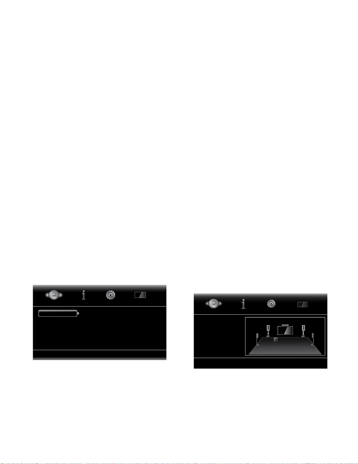
Speaker Settings: This option allows you to set up the receiver to work properly with
your speakers. There are two options:
• EzSet/EQ: This option makes the supplied EzSet/EQ microphone automatically
detect the capabilities of each connected speaker and optimize the BDS receiver’s
performance for your speakers. This will provide excellent results in most
installations.
• Manual Configuration: This option lets you manually configure the BDS receiver to
work with your speakers. Select this option if you wish to set up the receiver for
your speakers manually or if you are unable to run EzSet/EQ calibration.
With both options, the first step is to select the configuration of your speaker system:
• 2.0: This configuration consists of left and right main speakers but no subwoofer.
Selecting this configuration sends all of the bass to the left and right speakers, so
be sure that they are full-range and can handle deep bass.
• 2.1: This configuration consists of left and right main speakers, plus a subwoofer.
• 3.1: This configuration consists of front left, center and front right speakers, plus
a subwoofer.
• 5.1: This configuration consists of front left, front right, center, surround left and
surround right speakers, plus a subwoofer.
Manual Configuration: After you select your speaker system’s configuration, the speaker
setup screen will appear:
Audio Settings
Tone Controls
Audio Output
Speaker Settings
Select to adjust Bass & Treble
Tone controls: This option lets you increase or decrease the amount of bass (low
frequencies) and treble (high frequencies) in the sound. The adjustment ranges from
–10dB to +10dB, in 1dB increments.
Audio output: This option lets you set the following items:
HDMI Audio Out: In addition to digital video signals, the BDS receiver’s HDMI connection
also carries digital audio signals.
• PCM: This option outputs a two-channel downmix derived from the program’s native
audio format via the HDMI output.
• Off: This option turns the receiver’s HDMI audio output off. We recommend setting
this option to “Off,” so you can take full advantage of the superior audio capability
of your BDS receiver.
Bass
Treble
0dB
0dB
Audio Settings
Tone Controls
Audio Output
Speaker Settings
L (0.0 dB, 1m/3 ft)
R (0.0 dB, 1m/3 ft)
SUB
C
R
L
LS RS
17
Page 19
BDS 270/BDS 570
harman/kardon
BDS 270 + 570 Service Manual
Page 19 of 90
Setting Up the Receiver and Using the Receiver
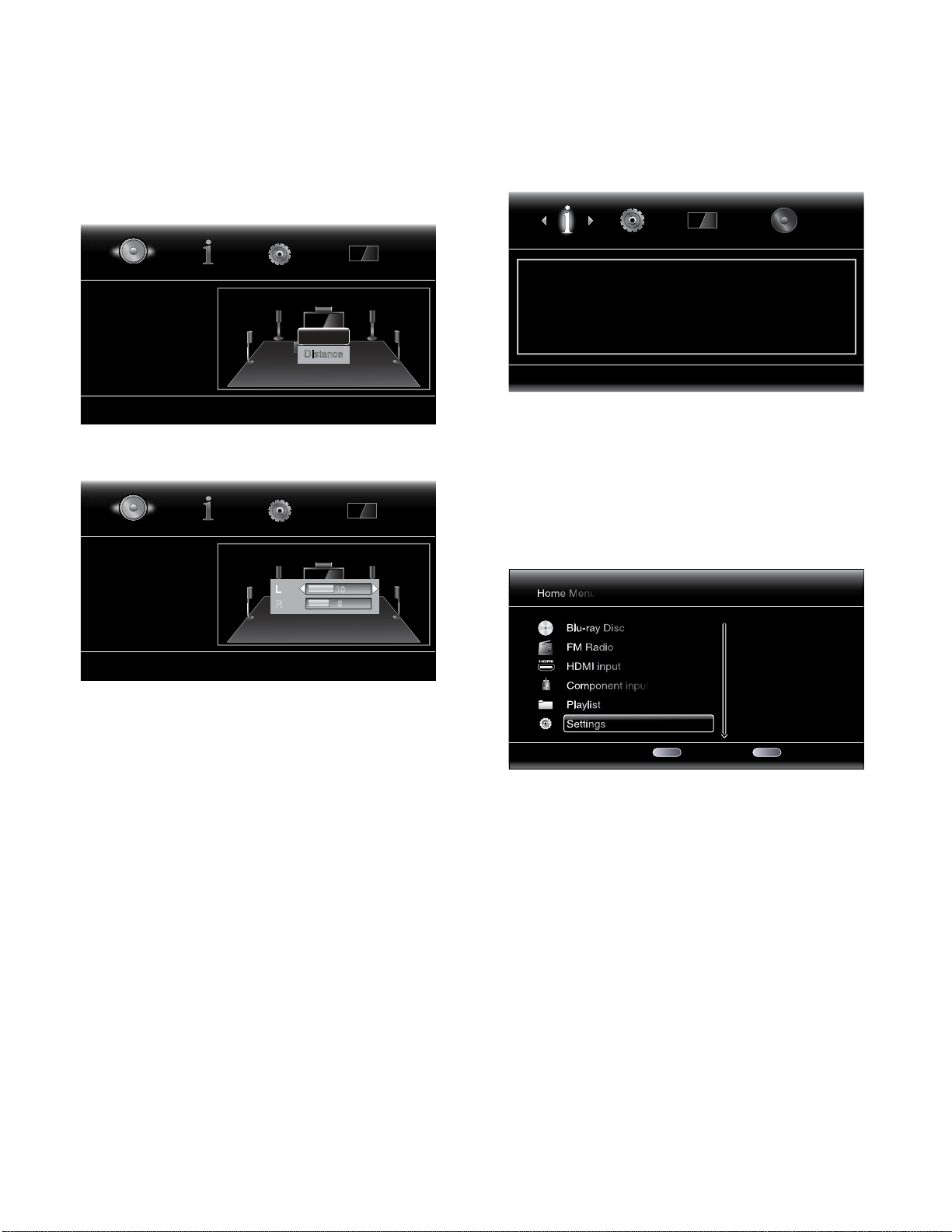
Setting the speaker distances:
1. The front left and front right speakers will be highlighted. Press the OK button. The
Level and Distance selection screen will appear.
Audio Settings
Tone Controls
Audio Output
Speaker Settings
L (0.0 dB, 1m/3 ft)
R (0.0 dB, 1m/3 ft)
L
LS RS
Distance
SW1
Level
C
R
2. Press the Cursor Down button to highlight Distance, and press the OK button. The
Distance adjustment bars will appear.
Audio Settings
Tone Controls
Audio Output
Speaker Settings
L (0.0 dB, 3.0m/10 ft)
R (0.0 dB, 2.4m/8 ft)
L
L
LS RS
R
SW1
C
10
R
8
3. Measure the distance from the listening position to each of your system’s speakers,
including the subwoofer. Write down the distances.
4. Use the Cursor Left and Right buttons to adjust the “L” bar until it shows the distance
you measured to the front left speaker (the arrowheads indicate which speaker is
being adjusted).
5. Press the Cursor Down button to highlight the “R” bar. Use the Cursor Left and Right
buttons to adjust the bar until it shows the distance you measured to the front right
speaker.
6. Press the Clear/Exit button twice to return to the speaker setup screen (the front left
and front right speakers will still be highlighted).
7. Press the Cursor Down button. The subwoofer will be highlighted. Press the OK
button. The Level and Distance screen will appear.
8. Repeat Steps 2 – 7 for the center speaker, surround speakers and subwoofer.
9. When you have entered the distances to all of your system’s speakers, press the
Clear/Exit button repeatedly to return to the Home Menu screen.
NOTE: Leave all the speaker levels set at “0” for now. You will be able to adjust the
individual speaker levels once your system is set up and you’re playing music or films.
See Adjusting Individual Speaker Volumes, on page 19.
Information Menu
Information
Software Version: BDS_X70 V2.01.16
MAC Address: 00 -1B -44 -12 -1D
Select to browse system information
The Information menu will display the receiver’s software/firmware version number and
the receiver’s factory-assigned network MAC address. This screen is for information
only and has no user adjustments.
Using the Receiver
NOTE: Before using your new BDS receiver, be sure to set the speaker distances, as
explained in Audio Settings: Speaker Settings, on page 17.
Home Menu
Press the Home button to display the Home Menu screen:
Home Menu
Blu-ray Disc
FM Radio
HDMI input
Component input
Playlist
Settings
1 / 5 Exit Option
HOME
The available sources are listed on the left.
If a disc has been inserted into the receiver’s built-in disc slot, it will appear on the list
as either “CDDA” (CD), “DVD Video” (DVD) or “Blu-ray Disc.” If you have inserted a USB
device into the receiver’s USB port, it will appear on the list as “USB.”
NOTE: Digital and analog audio sources connected to the receiver’s rear-panel digital
and line inputs will not appear on the list but can be selected using the remote’s “Aux”
Input button (see Listening to Audio Sources, on page 23).
Type: Settings
OPTIONS
18
Page 20
BDS 270/BDS 570
harman/kardon
BDS 270 + 570 Service Manual
Page 20 of 90
Using the Receiver
To select a source from the list, use the Cursor Up/Down buttons to highlight the desired
source, then press the OK button to select it. You can also select a source directly by
pressing its Input button on the remote.
EJECT POWER TV
Input
BRIDGE
RADIO
AUX
DISC
HDMI3
HDMI2
COMPONENT
HDMI1
1
4
7
REPEAT
HOME
CLEAR/EXIT
+ +
VOLUME
PROGRAM
BOOKMARK
SURROUND
TOP MENU
Buttons
2
3
5
6
8
9
0
DISPLAY
OPTIONS
OK
POP-UP
CHANNEL
MUTE
––
ZOOM
THUMBNAIL
To use the Playlist function, see Using Playlists, on page 25.
Adjusting Individual Speaker Volumes
You can adjust the volumes of the system’s individual speakers while you’re listening to
music or watching films.
1. Press the Home button and use the Cursor and OK buttons to select Settings. The
Settings menu will appear.
2. Select the Audio option. The Audio menu will appear.
3. Select Speaker Settings, then select Manual Configuration, and then select your
system’s speaker configuration. After you select your system’s configuration, the
speaker setup screen will appear.
Audio Settings
Tone Controls
Audio Output
Speaker Settings
L
LS RS
L (0.0 dB, 1m/3 ft)
R (0.0 dB, 1m/3 ft)
4. The front left and front right speakers will be highlighted. To adjust either of them,
press the OK button. To adjust a different speaker, use the cursor buttons to highlight
it, and press the OK button. The Level and Distance selection screen will appear.
SUB
C
R
5. Make sure that Level is highlighted, and press the OK button. The Volume adjustment
bars will appear.
Audio Settings
Tone Controls
Audio Output
Speaker Settings
L
L
LS RS
R
SW1
C
R
2
0
L (0.0 dB, 3.0m/10 ft)
R (0.0 dB, 2.4m/8 ft)
6. Select the speaker you want to adjust, and use the left and right arrow buttons to
adjust its volume. You can vary the volume from +10dB to –10dB, in 1dB increments.
7. Press the Clear/Exit button twice to return to the speaker setup screen (the front left
and front right speakers will still be highlighted). To adjust the volume of a different
speaker, use the cursor buttons to highlight it and press the OK button. Repeat
Steps 5 – 6 for that speaker.
8. When you are finished adjusting the volumes of all of your system’s speakers, press
the Clear/Exit button repeatedly to return to the Home Menu screen.
Notes on Setting Speaker Volumes in 5.1-Channel Systems:
While setting your system’s individual speaker volume levels is ultimately up to your
personal taste, here are some ideas you may find helpful:
• For films and video-music programs, your overall goal should be to create an
enveloping, realistic sound field that draws you into the film or music program
without drawing your attention away from the action on the screen.
• For multichannel music recordings, some music producers will create a sound field
that places the musicians all around you; others will create a sound field that places
the musicians in front of you, with more subtle ambience in the surround speakers
(as you would experience in a concert hall).
• In most 5.1-channel films, the surround channels are not intended to be as loud or
as active as the front channels. Adjusting the surround speakers so they are always
as loud as the front channels could make dialogue difficult to understand and will
make some sound effects sound unrealistically loud.
Notes on Setting Subwoofer Volume:
• Sometimes the ideal subwoofer volume setting for music is too loud for films, while
the ideal setting for films is too quiet for music. When setting the subwoofer volume,
listen to both music and films with strong bass content and find a “middle ground”
volume level that works for both.
• If your subwoofer always seems too loud or too quiet, you may want to place it in
a different location. Placing the subwoofer in a corner will always tend to increase
its bass output, while placing it away from any walls or corners will always tend to
lessen its bass output.
IMPORTANT: Do not turn the receiver’s volume up to or past the point where the audio
from the speakers becomes distorted. Doing so can damage the speakers.
Audio Settings
Tone Controls
Audio Output
Speaker Settings
L (0.0 dB, 1m/3 ft)
R (0.0 dB, 1m/3 ft)
Distance
SW1
Level
C
R
L
LS RS
19
Page 21

Using the Receiver and Using the Disc PlayerBDS 270/BDS 570
harman/kardon
BDS 270 + 570 Service Manual
Page 21 of 90
Surround-Sound Modes
Your BDS receiver can decode and play audio programs in these native audio formats:
• Dolby Digital
• Dolby Digital Plus
• Dolby TrueHD
• DTS Digital
™
• DTS-HD
• DTS-HD Master Audio
• PCM
• WMA (DRM-free version only): WMA9, CBR @192kbps, VBR @ 355kbps
• MP3: 32kbps – 320kbps bitrates, including variable bitrate encoding
The audio formats available for any particular program depend on the program and on
how you have configured your BDS receiver in the Audio Settings menu:
High Resolution Audio
™
Available Audio Formats
2.0- and 2.1Channel Setup
Configuration
2.1-Channel
Programs
3.1-Channel
Programs
4.1-/5.1-/6.1-
Channel
Programs
To switch between the available surround-sound modes for the program currently playing,
press the Surround button. Each press of the Surround button will change to the next
available mode in line. A pop-up display will appear on the TV, showing the modes as you
cycle through them.
Dolby Virtual
Speaker Wide
(default)/Dolby
Virtual Speaker
Reference/Stereo
Dolby Virtual
Speaker Wide
(default)/Dolby
Virtual Speaker
Reference/Stereo
Dolby Virtual
Speaker Wide
(default)/Dolby
Virtual Speaker
Reference/Stereo
3.1-Channel Setup
Configuration
Dolby PLII Movie
(default)/Dolby PLII
Music/Dolby Virtual
Speaker Wide/Dolby
Virtual Speaker
Reference/Stereo
Original (default)/
Dolby Virtual
Speaker Wide/Dolby
Virtual Speaker
Reference
Dolby Virtual
Speaker Wide
(default)/Dolby
Virtual Speaker
Reference/Stereo
5.1-Channel Setup
Configuration
Original (default)/
Dolby PLII Movie/
Dolby PLII Music/
Dolby Virtual
Speaker Wide/Dolby
Virtual Speaker
Reference/Stereo
Original (default)/
Dolby PLII Movie/
Dolby PLII Music/
Dolby Virtual
Speaker Wide/Dolby
Virtual Speaker
Reference/Stereo
Original (default)/
Dolby Virtual
Speaker Wide/
Dolby Virtual
Speaker Reference
Listening Through Headphones
Your BDS receiver’s headphone connection accepts a standard 1/8-inch (3.5mm) stereo
headphone plug. When you insert the headphone plug into the connector, the receiver’s
speaker outputs will mute; the HDMI audio output will not mute.
When headphones are connected to the receiver’s Headphone jack, pressing the
remote’s Surround button cycles between these two modes:
• HARMAN headphone, which virtualizes a multichannel surround soundtrack down
to two channels. This mode retains the soundtrack’s original directional cues,
allowing you to enjoy an enveloping surround-sound experience on any ordinary
pair of stereo headphones.
• Headphone Bypass, which downmixes surround-sound programs into normal
stereo. This mode does not retain any multichannel directional cues that may be in
the original surround-sound program.
Using the Disc Player
Disc Handling Precautions
• To keep the disc clean, handle the disc by its edge. Do not touch the surface.
• Do not stick paper or tape on the disc. If there is glue (or a similar substance) on the
disc, remove the substance completely before using the disc.
• Do not expose the disc to direct sunlight or heat sources such as hot air ducts or
leave it in a car parked in direct sunlight, as there can be a considerable rise in
temperature inside the car.
• After playing, store the disc in its case.
• Do not write on the label side with a ball-point pen or other sharp writing utensils.
• Be careful not to drop or bend the disc.
Disc Cleaning Precautions
• Before playing, clean the disc with a cleaning cloth. Wipe the disc from the center out.
• Do not use solvents such as benzine, thinner, commercially available cleaners or
anti-static spray intended for vinyl LPs.
Regional Coding
BDS receivers sold in the USA are designed only for playback of discs with Blu-ray Disc
region code A and DVD Region Code 1 information, or for discs that do not contain any
region code information.
BDS receivers sold in Europe are designed only for playback of discs with Blu-ray Disc
region code B and DVD Region Code 2 information, or for discs that do not contain region
code information.
Copyright
Audio-visual material may consist of copyrighted works that must not be recorded
without the permission of the owner of the copyright. Please refer to relevant laws
covering copyright protection.
Copy Protection
Your BDS receiver is in compliance with HDCP (High-Definition Copy Protection), and a
video display connected via the HDMI output must also be HDCP-compliant.
The BDS receiver supports Rovi copy protection. On Blu-ray Disc recordings and DVD
discs that include a copy-protection code, if the contents of the disc are copied using
a VCR, the copy-protection code prevents the videotape copy from playing normally.
Supported Disc Formats
The BDS receiver can play the following types of discs (5"/12cm, and 3"/8cm size):
• BD-Video (single-layer or double-layer)
• DVD-Video
• DVD+R/+RW
• DVD-R/-RW
• CDDA (CD digital audio)
• CD-R/RW
NOTE: The compatibility and performance of dual-layer discs is not guaranteed.
20
Page 22
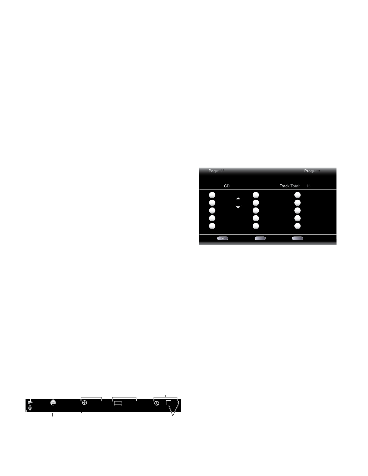
BDS 270/BDS 570
harman/kardon
BDS 270 + 570 Service Manual
Page 22 of 90
Using the Disc Player
Supported Media Codecs
The BDS receiver can play media recorded in the following audio/video codecs:
• MPEG 1, Layer 1
• MPEG 2, Layer 2
• MPEG 2, Layer 3
• H.264
• VC-1
• MP3 (from CD-R/RW, DVD+R/+RW, BD-R/RE and USB)
• JPEG (from CD-R/RW, DVD+R/+RW, BD-R/RE and USB)
• DivX 3.x/4.x/5.x (from CD-R/RW, DVD+R/+RW and USB)
• WMA (WMA9, CBR at 192kbps, VBR at 355kbps, DRM-free)
NOTE: Due to differences in the formats of certain discs, some discs may include a mix
of features, some of which are not compatible with the disc player. Similarly, although
Blu-ray Disc recordings and DVDs are capable of a wide range of features, not every
disc includes every capability of its system. For example, although the BDS receiver is
compatible with multi-angle discs, the multi-angle feature is possible only when the disc
is specially encoded for multiple-angle play. To make certain that a specific feature or
soundtrack option is available, please check the options noted on the disc jacket.
The playback capability of recordable discs may vary due to variations in the quality of the
disc and the recorder used to create the disc.
Loading and Playing a Disc
Hold the disc horizontally when loading it, and insert it gently into the Disc slot. The disc
loading mechanism will take the disc and slide it into the unit.
• Do not load more than one disc into the Disc slot.
• Do not load the disc upside down.
After loading a disc into the player, press the Play button to begin playback.
Use the Play, Pause, Stop, Prev/Step, Next/Step, Search Down/Slow and Search Up/Slow
buttons to control disc playback. See Remote Control Functions, on page 8, for more
information about the functions of these buttons.
Playback Features
Repeat: When you are playing a Blu-ray Disc recording or DVD, pressing the Repeat
button cycles through the following repeat modes: Chapter, Title, All, Off. When you are
playing a CD, this button cycles through the following repeat modes: Track, All, Off.
A-B: When playing a Blu-ray Disc recording, DVD or music CD, pressing the A-B button
places the player into the A-B repeat mode. The first press sets the “A” repeat point;
the second press sets the “B” repeat point and begins repeating the section of the disc
between the two points. Pressing the A-B button while the player is in the A-B repeat
mode takes the player out of that mode. Note: This feature is disc-dependent. Not all
Blu-ray Disc recordings support A-B repeat.
Find: Pressing the Find button during disc playback activates the search function, allowing
you to jump to a specific location on the disc. You can find a location by title, chapter or
time. See Top Menu Button (on this page) for more information. NOTE: Not all discs allow
searching by title. On these discs, use the disc menu to change titles.
Options: Pressing the Options button displays any available options for the currentlyplaying disc. Blu-ray Disc options include title, chapter, time display, audio options, angle
options and subtitle options. DVD options include title, chapter, time display, playback
modes, audio options and angle options. Audio CD options include track selection, time
display, playback modes, bitrate, instant search and instant replay.
Display button: When playing Blu-ray Disc recordings and DVDs, pressing the Display
button toggles the information bar on and off.
Playback
Mode
Disc Type &
Encoding
MPEG 1 / 8 00 : 32 : 37
DVD-VIDEO
English Dolby Digital 5.1
1/1
Current
Title
1 / 2
Current
Chapter
Time
Display
TT
Top Menu button: Pressing this button displays the top menu for the Blu-ray Disc
recording or DVD that is currently playing. NOTE: This feature is disc-dependent. Not all
DVDs have top menus. If the DVD has no top menu, pressing the Top Menu button may
display the disc menu, depending on how the disc’s menu system was authored.
Pop-Up button: Pressing this button while playing a Blu-ray Disc recording displays the
pop-up menu. (DVDs will display the disc menu.) Note: If the Blu-ray Disc recording does
not support a pop-up menu, the disc menu will be displayed.
Bookmark function: The bookmark function lets you mark up to 12 locations on the
disc currently playing. Press the Bookmark button to mark the current location on the
disc. To play the disc from one of your selected bookmark locations, hold the Bookmark
button to display the bookmark list. Use the Navigation left/right buttons to select the
desired bookmark, and press the OK button to play the disc from that location. NOTE: The
bookmark function is disc-dependent. Not all discs allow bookmark operation.
Programmed play: This option lets you create a programmed playlist for a disc. The
program function works for CDs, DVDs and some Blu-ray Disc recordings (not all
Blu-ray Disc recordings allow programmed play).
1. Press the Program button. The Program screen will appear.
Page: 1/ Program
CD Track Total: 15
1
2
3
4
5
Track: 10
Track: 05
-- -- -- --
-- -- -- --
-- -- -- --
Play Clear Stop
-- -- -- --
6
-- -- -- --
7
-- -- -- --
8
-- -- -- --
9
-- -- -- --
10
CLEAR EXIT
11
12
13
14
15
-- -- -- --
-- -- -- --
-- -- -- --
-- -- -- --
-- -- -- --
2. Press the OK button and use the Navigation Up/Down buttons to select the title on the
disc (Blu-ray Disc/DVD) or track (CD) for your first program entry.
3. Press the right Navigation button and use the Navigation Up/Down buttons to select
the chapter for your first program entry (Blu-ray Disc/DVD only).
4. Repeat Steps 2 – 3 for every entry in your programmed list.
5. When you’re finished programming your list, press the Play button to play the list.
The programmed list will remain active until the list has completed playing. Pressing the
Stop button twice or ejecting the disc deletes the programmed list.
BD-Live Interactivity
BD-Live interactivity is available on select Blu-ray Disc recordings. When you select the
BD-Live features from a disc’s menu, you may be able to download additional content or
other information via the Internet (through the Network connection).
If you have difficulty accessing the Internet while using a BD-Live disc, press the Settings
button and navigate to the Network Setup menu. Select “Test Connection.” If the BDS
receiver is able to access the Internet, then the computer server the BD-Live disc is
trying to access may be at fault. Check the disc jacket for more information or contact
the content provider. If the “Test Connection” function fails, contact your Internet service
provider (ISP) to obtain the correct settings for the BDS receiver’s IP Configuration menu.
If the problem persists, contact your ISP for further assistance.
Audio
Mode
“Find”
Indicators
21
Page 23

BDS 270/BDS 570
harman/kardon
BDS 270 + 570 Service Manual
Page 23 of 90
Using the Disc Player, Listening to Your
iPod/iPhone Device and Using the Radio
Playing Music CDs
When the BDS receiver is playing a music CD, the top bar shows the current playbackmode icon, the type of disc, the track currently playing, the number of total tracks on the
disc and the time display.
Playback
Mode
Disc
Type
CDDA
Current
Track
TRACK
Time
Display
00 : 32 : 37
Total
Tracks
1 / 15
T
Listening to Your iPod/iPhone Device
Playing iPod/iPhone Content
Insert your iPod or iPhone device into a The Bridge IIIP dock (optional, not supplied) and
press the BDS receiver remote control’s iPod button. If the Home screen is displayed,
highlight iPod and press the OK button. The iPod Now Playing screen will appear on the TV.
NOTE: The BDS receiver will not play video content stored on iPod or iPhone devices.
In addition to playing content from an iPod or iPhone device, pressing the iPod button
places the remote in the iPod control mode. Use the following remote control buttons
to browse and select content on your iPod/iPhone device and control the device during
playback:
Cursor and OK buttons: Use these buttons to navigate and select items from the iPod/
iPhone menus.
Exit button: Pressing this button while playing content displays the iPod/iPhone menu.
Pressing this button while a menu is displayed exits that menu and displays the previous
screen.
Previous/Step button: Press this button once to skip to the beginning of the current
track. Press the button twice to skip to the beginning of the previous track.
Next/Step button: Press this button to skip to the beginning of the next track.
Search/Slow Reverse button: Press this button to search backward through the
current track.
Search/Slow Forward button: Press this button to search forward through the current
track.
Stop button: Press this button to stop playback.
Play button: Press this button to play the item appearing on the receiver’s display.
Pause button: Press this button to pause the item that is playing. Pressing this button
while the iPod/iPhone device is paused will resume play.
Channel +/– buttons: Pressing the Channel + button moves up ten items in the active
menu. Pressing the Channel – button moves down ten items in the active menu. Use
these buttons to navigate through long menu lists quickly.
Home button: Pressing the Home button will switch the display to the Home screen
while you continue to hear the iPod/iPhone content through the BDS receiver. To display
the iPod Now Playing screen again, press the Exit or Cursor Left button.
Red button: Pressing the red button will toggle between the following modes: Random
Play (albums), Random Play (songs), Random Off.
Repeat button: Pressing the Repeat button will cycle the iPod/iPhone device between
Repeat Song, Repeat All, Repeat Off.
Receiver Information Display
When songs are playing, the display’s top line will scroll “Artist <Artist Name>,” “Song
<Song Name>.” The display’s bottom line will show the time according to the iPod/
iPhone time display. When the iPod/iPhone device is in the menu mode, the receiver’s
display will mimic the behavior of the menu that is active on the iPod/iPhone screen.
Using the Radio
Press the Radio button on the remote control, or if the Home screen is displayed on the
TV, highlight Radio and press the OK button. The Radio Now Playing screen will appear
on the TV.
The top line of the receiver’s information display will show the currently tuned-in FM
frequency; the bottom line of the display will show the RDS information for the currentlytuned station (if available).
In addition to playing the radio through the receiver, pressing the Radio button places the
remote in the radio-control mode. Use the following remote-control buttons to control
the receiver’s FM radio:
Cursor Up/Down buttons: Pressing these buttons increases or decreases the tuned
frequency by 0.05MHz.
OK button: Pressing this button sets the currently tuned-in frequency as a preset
station. See Setting and Recalling Preset Stations, below, for details.
Previous/Step button and Next/Step button: Pressing these buttons scans to the next
higher or lower receivable radio station.
Search/Slow Reverse button and Search/Slow Forward button: Pressing these
buttons scans to the next higher or lower receivable radio station.
Channel +/– buttons: Pressing these buttons changes to the next higher or lower
preset station.
Number buttons: Pressing a number button or a combination of number buttons will
change to the corresponding preset station. See Setting and Recalling Preset Stations,
below, for details.
Home button: Pressing the Home button will switch the TV to the Home screen while the
radio continues to be heard through the BDS receiver. To display the Radio Now Playing
screen again, press the Exit or Cursor Left button.
Setting and Recalling Preset Stations
You can set up to 30 preset stations for easy recall.
To set the currently tuned-in station as a preset:
1. Press and hold the OK button for three seconds. The bottom line of the receiver’s
information display will read “Set Preset _ _,” with the “_ _” characters flashing.
2. Use the number buttons to enter the preset number you want the current station
saved to. If you do not enter a number within ten seconds, the display line will revert
back to the RDS text readout for the current station.
22
Page 24
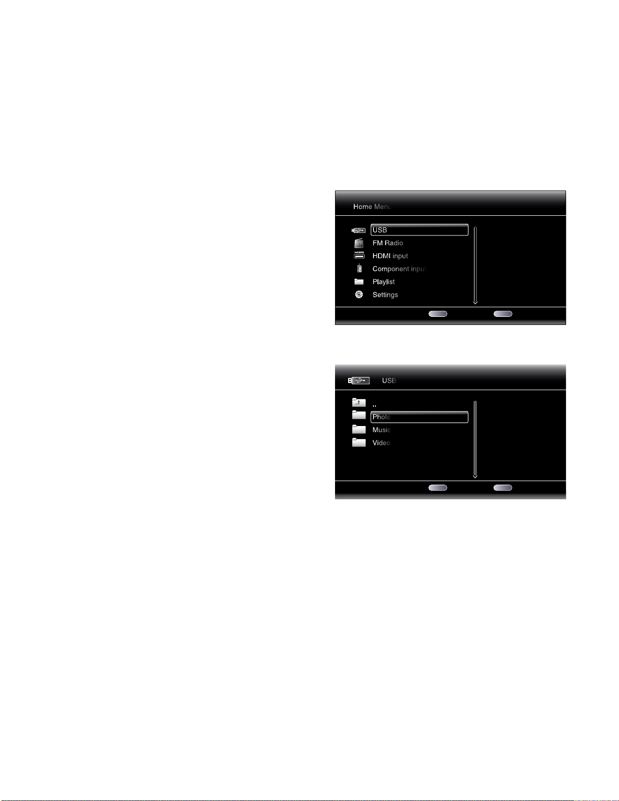
1 / 6 Exit Option
Home Menu
USB
FM Radio
HDMI input
Component input
Playlist
Settings
HOME
OPTIONS
Type:USB
Size:595.375M
FS:FAT32
1 / 3 Exit Option
Type:Folder
USB
..
Photo
Music
Video
HOME
OPTIONS
BDS 270/BDS 570
harman/kardon
BDS 270 + 570 Service Manual
Page 24 of 90
Using the Radio, Listening to Audio Sources and
Playing Files from USB Devices and CD Data Discs
To listen to a preset station:
Press the Channel + or Channel – button. The radio will tune to the next higher or lower
preset station.
– OR –
Use the number buttons to enter the preset number.
• For presets 1 – 9, press the corresponding 1 – 9 button.
• For presets 10 and higher, press the “0” button, then use the number buttons to enter
the preset number.
Listening to Audio Sources
Press the Aux button on the remote control. The receiver will switch to the audio input
that was selected last. Subsequent presses of the Aux button will advance through the
audio inputs in the following order: Coaxial Digital, Optical Digital 1, Optical Digital 2,
Analog L/R 1, Analog L/R 2 and the HDMI Audio Return Channel.
The Aux Input Now Playing screen will appear on the TV.
Playing Files from USB Devices and CD Data Discs
Your BDS receiver can play MP3 (up to 320kbps bitrate) audio files, display JPEG photos
and show MPEG 1 (layer 1), MPEG 2 (layers 2 and 3), and DivX home theater profile
audio/video files stored on a USB device or a CD data disc.
IMPORTANT: Only media in the FAT32 file system are compatible with your BDS receiver.
To access files on a device inserted into the receiver’s USB port, press the Home button
and select USB from the source list on the screen.
Regardless of the device’s file structure, the screen will first show three individual folders
named “Photo,” “Music” and “Video.” Select the type of media you want to play from
these three folders.
In addition to playing the Aux source through the receiver, pressing the Aux button places
the remote in the Aux-control mode. If you programmed the remote to control auxiliary
components (either by entering in a code number or teaching commands to the remote),
the remote will now operate according to that programming.
Lip sync delay: When playing an Aux source, audio and video processing circuitry may
create a slight delay between the picture and sound. Pressing the Options button lets
you adjust the audio delay to eliminate “lip sync” errors that may occur between the
sound and picture in video programs with sound playing through one of the receiver’s
rear-panel audio inputs. Use the Cursor Up/Down buttons to increase or decrease the
audio delay until the perceived lip-sync errors disappear and the sound and picture are
properly synchronized. The amount of audio delay is shown on the receiver’s front-panel
Information display.
The screen will then show the device’s file structure. Selecting a folder will show all files
of the selected type of media in the folder. If there are files of the selected type in the
device’s root directory, they will also be shown.
To move up one directory level, press the Cursor Left button or select the arrow folder.
23
Page 25
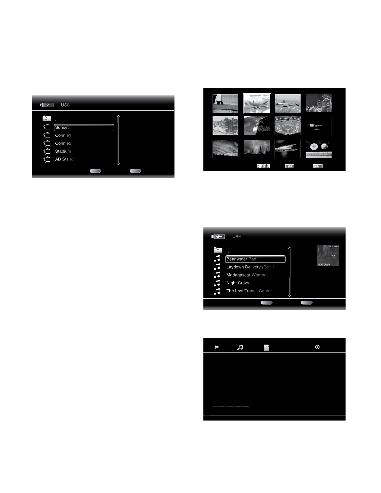
01 / 31 Exit Option
Type:JPG
Size:0.241M
Resolution:720x524
USB
..
Sunset
Connie1
Connie2
Stadium
AB Stand 1
HOME
OPTIONS
1 / 25 PreviousMove Next
01 / 10 Exit Option
Type:MP3
Total Time:03:29
Title:Beanwater Junction, Part 1
Artist:Jugalbandi
Album:Night Crazy
Genre:Progressive
USB
..
Beanwater Part 1
Laydown Delivery (Edit 1)
Madagascar Wombat
Night Crazy
The Lost Transit Center
HOME
OPTIONS
Type: MP3
Total Time: 03:29
Title: Beanwater Junction, Part 1
Artist: Jugalbandi
Album: Night Crazy
Genre: Progressive
00 : 02 : 37
1 / 10
BDS 270/BDS 570
harman/kardon
BDS 270 + 570 Service Manual
Page 25 of 90
Playing Files from USB Devices and CD Data Discs
Viewing Photos
In the top directory, select “Photo.” Select a folder containing photo files and highlight a
photo file in the folder. A thumbnail of the highlighted photo will appear on the right of
the screen.
Use these remote buttons while viewing photos:
Play button: Press this button to begin a slide show that displays the photos in the current
folder or directory level (starting with the highlighted JPEG) for 15 seconds in the order
they appear in the folder.
Pause button: Press this button to freeze the current photo on the screen. Press the Play
button to resume the slide show.
Stop button: Press to end the slide show and return to the directory.
Next/Step and Previous/Step buttons: Press these buttons to skip to the next or
previous photo file in the slide show or directory.
Cursor Up button: Pressing this button while a photo is displayed rotates the photo 180°.
Pressing this button while the directory list is displayed highlights the previous item in
the directory.
Cursor Down button: Pressing this button while a photo is displayed shows a mirrorimage reflection of the photo. Pressing this button while the directory list is displayed
highlights the next item in the directory.
Cursor Left button: Pressing this button while a photo is displayed rotates the photo 90°
counterclockwise. Pressing this button while the directory list is displayed jumps to the
next higher directory level.
Cursor Right button: Pressing this button while a photo is displayed rotates the photo
90° clockwise.
Options button: Pressing this button while a photo is displayed shows the Options menu,
which gives you the following options:
• File: Select a file to view.
• Play Mode: View files in their normal order, in random order (until you press the Stop
button) or in shuffle order (displays each image in the folder one time in random
order, then returns to the directory).
• Slide Show: Select the amount of time you want each slide to be displayed: 5
seconds, 15 seconds or 30 seconds.
• Transition: Select from various types of image-to-image transitions.
Pressing the Options button when a directory is displayed shows the Playlist Options box.
See Using Playlists, on page 25, for more information.
Thumbnail (Yellow) button: Pressing this button while playing a slide show displays
thumbnail images of all photos in the slide show. Use the Cursor and OK buttons to
highlight and select images to view.
Zoom (Blue) button: Pressing this button during a slide show freezes an image and
zooms in 2x size. Additional presses of the button change the zoom to 3x, 4x, 1/2x, 1/3x
and 1/4x size.
Playing Music Files
In the top directory, select “Music.” Select a folder containing music files and highlight
a music file in the folder. Information about the highlighted file will appear on the right
of the screen.
Selecting a music file plays the file. If there are other music files in the folder that follow
the selected file, the receiver will play them in the order they appear on the on-screen
display. The following screen will appear while music files play:
24
Page 26
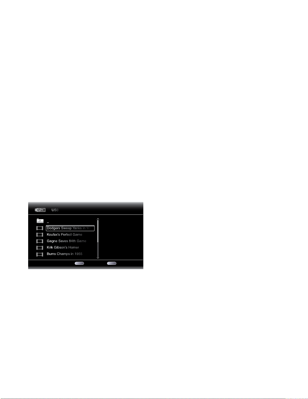
01 / 7 Exit Option
Type:MPEG
USB
..
Dodgers Sweep Yanks in ‘63
Koufax’s Perfect Game
Gagne Saves 84th Game
Krik Gibson’s Homer
Bums Champs in 1955
HOME
OPTIONS
BDS 270/BDS 570
harman/kardon
BDS 270 + 570 Service Manual
Page 26 of 90
Playing Files from USB Devices and
CD Data Discs, and Using Playlists
If a selected MP3 file has an album cover-art ID3 tag, the art will be displayed on the
screen.
Use the Play, Pause, Stop, Prev/Step, Next/Step, Search Down/Slow and Search Up/Slow
buttons to control music-file playback. See Remote Control Functions, on page 8, for
more information about the functions of these buttons.
When the BDS receiver is playing music files from a USB device or CD data disc,
the Repeat and Options functions are slightly different from when they are playing
Blu-ray Disc recordings, DVDs and music CDs:
Repeat button: Pressing this button cycles through the following repeat modes:
1 (song), All (folder), Off. The active repeat mode is indicated in the screen’s top bar.
Options button: Pressing this button displays any available options for the song
currently playing:
• File: Select a song to play.
• Time: Display the track’s elapsed time or the track’s time remaining.
• Play Mode: Plays songs in their normal order, in random order (until you press the
Stop button) or in shuffle order (plays each song in the folder one time in random
order, then returns to the directory).
• Bitrate: Shows the bitrate of the song currently playing.
• Advance: Performs a rapid, audible search forward through the song.
• Replay: Each press of the OK button jumps back ten seconds during play.
• Transition: Select from various types of image-to-image transitions (fade, wipe, etc).
While playing music files from a USB device or data CD, you can also view photos that
are on the same media. Press the Home button while the music file is playing, navigate
to a folder containing photo files, and select a photo file to begin a slide show.
Playing Videos
In the top directory, select “Video.” Select a folder containing video files and highlight a
video file in the active folder.
Options button: Pressing this button displays any available options for the song
currently playing:
• File: Select a file to play.
• Title: Select a title to play (if available).
• Chapter: Select a chapter to play (if available).
• Time: Display the elapsed time or the time remaining.
• Play Mode: Plays videos in their normal order, in random order (until you press the
Stop button) or in shuffle order (plays each video in the folder one time in random
order, then returns to the directory).
• Audio: Select audio options (if available).
Using Playlists
Because USB devices and CD data discs can contain large numbers of playable files,
you can create a playlist for each that will make it easier for you to access selected files.
To Create a Playlist:
NOTE: The procedure is the same for a CD data disc playlist and a USB playlist.
1. Press the Home button. The Home menu will appear.
2. Select CD data disc or USB. The Photo, Music and Video folders will appear.
3. Select the type of file you want to create the playlist for. You can create a playlist for
each type of file.
4. As you search through the directory structure, when you see a file you want to include
in the playlist for that file type, highlight it and press the Options button. The playlist
options box will appear.
5. To add the item to the playlist, select “Add to playlist.”
6. Repeat Steps 4 – 5 for all items you want to add to the playlist.
To create a playlist for a different file type, repeat Steps 1 – 6, but in Step 3, select a
different file type.
To Play a Playlist:
1. Press the Home button. The Home menu will appear.
2. Select Playlist. The Photo/Music/Video screen will appear.
3. Select the file type of the playlist you want to play. The playlist will open.
4. Select the first item in the playlist and press the Play button. The playlist will play.
To repeat the playlist, press the Repeat button. You can repeat one item (“1”) or the entire
playlist (“All”).
The video will automatically play. If there are other video files in the folder, the BDS
receiver will play each one in the order they appear on the on-screen menu.
Use the Play, Pause, Stop, Prev/Step, Next/Step, Search Down/Slow and Search Up/Slow
buttons to control music file playback. See Remote Control Functions, on page 8, for
more information about the functions of these buttons.
When the BDS receiver is playing video files from a USB device or CD data disc, the
Repeat and Options functions are slightly different from playing Blu-ray Disc recordings
and DVDs:
Repeat button: Pressing this button cycles through the following repeat modes:
1 (current video), All (folder), Off.
25
Page 27

BDS 270/BDS 570
harman/kardon
BDS 270 + 570 Service Manual
Page 27 of 90
Troubleshooting
If your BDS receiver isn’t performing the way you think it should, check to see if the problem is
covered in this section before calling your dealer or contacting a Harman Kardon representative.
Problem Solution
Troubleshooting
The receiver won’t power up (the Power indicator is not lit): • Check that the receiver’s Power cord is properly plugged into the receiver’s AC
Sound plays through the speakers, but there is no TV picture: • Check the HDMI connection between the receiver and the TV.
There is no sound coming from just the subwoofer: • Check that the subwoofer’s Power cord is plugged into a working AC outlet.
There is a constant hum in the sound: • Check that all input cables are plugged all the way into their connectors.
The disc does not play: • Check that the disc is inserted correctly (label side up).
There is noise or other interference in the picture while playing a Blu-ray Disc recording
or DVD:
The sound and picture are out of sync when playing to an Aux source: • Press the Options button and perform the Lip Sync adjustment to bring the sound
Cannot tune in radio stations: • Check that the FM antenna is correctly connected.
The receiver does not respond to remote-control commands: • Replace all three remote-control batteries with fresh ones, and make sure that they
The remote does not control programmed components (TV or video): • Check that you have pressed the remote’s Aux button before trying to operate the
The Ø symbol appears on the screen when you press a remote-control button: • The selected function is not permitted at the time the button is pressed.
The receiver does not respond to commands, or it behaves in an erratic way: • Unplug the receiver’s Power cord from the AC outlet, wait 30 seconds, then plug
You can find additional troubleshooting information in the FAQs link on the Support page at www.harmankardon.com.
26
Power connector.
• Check that the Power cord is plugged into a working AC outlet. If the outlet is
controlled by a switch, make sure the switch is set in the “On” position.
• Check that the receiver’s Main Power switch (located on the rear panel) is in the
“On” position.
• Check the HDMI connection or Component Video connection between the source
device and the BDS receiver.
• Check that the TV is turned on and is set to the proper input source.
• Unplug the HDMI cable from the TV and plug it back in again.
• Check that the subwoofer’s Power switch is in the “On” position.
• Check that the Subwoofer Level control is not turned all the way down (fully
counterclockwise).
• Check that the audio connection between the receiver and the subwoofer has been
properly made.
• Check the receiver’s Settings: Configuration menu to make sure that the subwoofer
volume has not been set at –10dB.
• Check that all cables are at least 10 ft (3.3m) from fluorescent lights.
• Check that all cable connectors are clean. If necessary, wipe them with a cloth
slightly moistened with alcohol.
• Set the subwoofer’s Power switch to “Off.” If the hum goes away, there is a ground
loop between the subwoofer and the receiver. Plugging the subwoofer’s Power cord
into the same AC outlet that the receiver is plugged into should eliminate the ground
loop.
• Check that the disc is the correct type: BD-Video (single-layer or double-layer),
DVD-Video, DVD+R/+RW, DVD-R/-RW, CDDA (CD digital audio), CD-R/RW. Other
disc types will not play.
• Check that the disc surface is clean and not scratched.
• Check that the disc surface is clean and not scratched.
and picture into synchronization.
• Adjust the antenna’s position. If necessary, use a powered FM antenna or an
outdoor FM antenna.
are installed with the correct polarity.
• Hold the remote closer to the receiver.
• Check that the receiver’s remote sensor is in the line of sight of the remote control.
component.
• Re-program and/or re-teach the component’s commands into the remote.
it back in.
Page 28

BDS 270/BDS 570
harman/kardon
BDS 270 + 570 Service Manual
Page 28 of 90
Aux Component Remote-Control Code List
TV/DVR
Aux Component Remote-Control Code List
Manufacturer Code Numbers
ADMIRAL 0192 0123 1088 1105
AIWA 1110
AKAI 1011 1020 1022 1042 1053
1056 1089 1093
ALBA 1020 1040
ANAM 0122 0112 0109 0106 0045
AOC 0128 0123 0122 0037
APEX 2014 2016
ARC EN CIEL 1017 1019 1024 1056 1059
ARCAM 1017
ARISTONA 1022 1023 1025 1033 1047
1048 1060 1086
ASA 1012 1023 1088 1096 1201
AUDIOVOX 0012
AUTOVOX 1025 1044 1088
BANG & OLUFSEN 1088
BARCO 1202
BASICLINE 1020
BAUR 1075 1076 1077 1102
BEKO 1022
BLAUPUNKT 0084 1011 1075 1076 1077
BRANDT
ELECTRONIQUE
BRION VEGA 1023 1088 1203
BROCKSONIC 0206 0205
BUSH 1010 1020 1040 1043 1092
BUSH (UK) 1044
CENTURY 1023 1088
CITIZEN 0132 0128 0123 0045
COMTEL 1032
CONTEC 0045
CONTINENTAL
EDISON
CRAIG 0159 0158 0157 0045
CROSLEY 1023 1088
CROWN 0132 0045
CURTIS MATHES 0128 0123 0132
1017 1019 1024 1056 1059
1017 1019 1024 1056 1059
Manufacturer Code Numbers
DAEWOO 0132 0128 0127 0119 0116
0114 0111 0108 0106 0105
0102 0087 1022
DANSAI 1022
DAYTRON 0132 0128
DECCA 1091 1032
DECCA (UK) 1038
DEGRAAF 1015
DISH NETWORK 2012
DIXI 1022
DUMONT 1201 1199 1096 1088 1023
DUMONT-FINLUX 1044 1012
DYNATECH 0063
DYNATRON 1022 1020
DYNEX 0014
ELECTROHOME 0132 0115
EMERSON 0205 0162 0159 0158 0157
0139 0132 0128 0123 0045
1195 1088
FUJITSU 0041 0042
FUNAI 0045
FUTURETECH 0045
GE 0163 0159 0145 0133 0128
0123 0121 0087 0029
GRUNDIG 0193
HALL MARK 0128
Harman Kardon 0201
HITACHI 0147 0144 0132 0128 0123
HYTEK 0016
INKEL 0120
JCPENNEY 0145 0132 0128 0123 0115
JENSEN 0019
JVC 0134 0087 0079
KEC 0045
KLH 0006
KTV 0162 0132 0123 0045
27
Page 29

BDS 270/BDS 570
harman/kardon
BDS 270 + 570 Service Manual
Page 29 of 90
TV/DVR
Aux Component Remote-Control Code List
Manufacturer Code Numbers
LG (GOLDSTAR) 0132 0128 0122 0110 0101 0002
0013 2004
LLOYTRON 0173 0172
LODGENET 0069
LXI 0148 0145 0077
MAGNAVOX 0148 0145 0132 0128 0123 0030
0040 2007 2008 2009 2010 2011
MARANTZ 0148 0123 0115
MEMOREX 0128 0069
METZ 0084
MGA 0128 0123 0115
MITSUBISHI 0168 0167 0160 0128 0123 0115
0077
MTC 0176 0175
MOTOROLA 2005
NATIONAL 0182 0181 0180 0179 0177 0148
NEC 0125 0123 0121 0115 0010
OLEVIA 0007
OPTONICA 0077
ORION 0211 0210 0209 0208 0207
PANASONIC 0169 0148 0087
PHILCO 0148 0132 0128 0123 0115 0045
PHILIPS 0148 0145 0132 0128 0123 0036
0035 0034 0033
PIONEER 0128 0123 0024
POLAROID 0003 0004 0005 0006 0043
PORTLAND 0132 0128
PROSCAN 0133
PROTON 0165 0132 0128 0122 0059 0008
QUASAR 0087 0032
RADIO SHACK 0197 0196 0180 0132 0128 0045
RCA 0163 0161 0145 0133 0128 0123
0115 0021 2001 2012
REALISTIC 0196 0167 0045
RUNCO 0153 0152 0044 0046
SAMPO 0128 0123 0059
Manufacturer Code Numbers
SAMSUNG 0145 0132 0128 0124 0022 0020
2003
SANYO 0054 0026
SCOT T 0132 0128 0045
SEA RS 0145 0132 0128
SHARP 0132 0128 0077
SIEMENS 0084
SIGNATURE 0069
SONY 0212 0194 0136 0130 0117 0031
0028
SOUNDESIGN 0128 0045
SYLVANIA 0148 0145 0128 0123 0025
SYMPHONIC 0184
TANDY 0077
TATUNG 0063 2018
TECHNICS 0181
TECHWOOD 0128
TEKNIKA 0132 0128 0123 0115 0069 0045
TELERENT 0069
TERA 0156
THOMSON 0191 0190
TIVO 0051 0052 2020 2021
TMK 0128
TOSHIBA 0202 0129 0063
TOTEVISION 0132
VIDEO
CONCEPTS
VIDTECH 0128
VIEWSONIC 0011 0038 0039 0047
VIZIO 0001 0002
WARDS 0148 0132 0128 0069
WESTINGHOUSE 0017 0018 0023
YAMAHA 0128 0123
YORK 0128
ZENITH 0090 0069 2002 2008 2019
0160
28
Page 30

BDS 270/BDS 570
harman/kardon
BDS 270 + 570 Service Manual
Page 30 of 90
Cable Tuners
Aux Component Remote-Control Code List
Manufacturer Code Numbers
ABC 3011 3001
ALLEGRO 3111
AMERICAST 3212
ARCHER 3112
BELCOR 3113
BT CABLE 4007
CABLE STAR 3113 3033
CABLETIME 4008 4011 4012 4016
CITIZEN 3111
CLYDE
CABLEVISION
COMCAST 3007 4014
DESCAT CANAL 4010
DIGI LINK 3114
EAGLE 3186
EASTERN 3070 3066
EMERSON 3112
FILMNET 4018 4020
FOXTEL 4019
FRANCE TELECOM 4013 4021
G.I. 3097 3096 3017 3011 3001
GC ELECTRONICS 3113
GEC 4017
GEMINI 3060 3032
GENERAL 3210
GENERAL
INSTRUMENT
HANLIN 3208 3175 3117 3101 3100 3099
HITACHI 3188 3001
JASCO 3111
JERROLD 3210 3188 3162 3097 3096 3073
LINSAY 3118
MACOM 3191
MAGNAVOX 3068 3019 3017
MOVIE TIME 3039 3035
NSC 3190 3035
4017
3210
3056
3017 3011 3002 3001 4001 4022
Manufacturer Code Numbers
OAK 3220 3197
PACE 3179
PANASONIC 3214 3189 3177 3176 3053
PANTHER 3114
PHILIPS 3090 3085 3020 3019 3013 4023
PIONEER 3216 3215 3209 3171 3119 3041
3001 4002
RADIO SHACK 3213 3112 3111
RCA 3214 3053
RECOTON 3116
REGAL 3208 3101 3100 3099 3056
REMBRANDT 3032
SAGEM 4028
SAMSUNG 3003 3186 3072 4002 4003 4024
SATBOX 4004
SCIENTIFIC
ATLANTA
SEAM 3121
SIGNATURE 3188 3001
SPRUCER 3189 3177 3081 3053
STARCOM 3163 3011 3002
STARGATE 3120
TANDY 3024
TELECAPATION 3028
TELESERVICE 4011
TEXSCAN 3036
TFC 3122
TIVO 3029 3030 4029 4030
TOCOM 3205 3170
TUDI 4027
UNITED CABLE 3011 4001
UNIVERSAL 3113 3042 3039 3034 3033
VIDEOWAY 3211 3124
VIEWSTAR 3190 3089 3086 3053 3025 3019
VISIOPASS 4009
WESTMINSTER
CABLE
ZENITH 3219 3211 3125 3065
3222 3221 3203 3183 4005 4006
4025 4026
4007
29
Page 31

BDS 270/BDS 570
harman/kardon
BDS 270 + 570 Service Manual
Page 31 of 90
Satellite Tuners
Aux Component Remote-Control Code List
Manufacturer Code Numbers
AIWA 6041
AKAI 6033
ALBA 6001 6011
AMSTRAD 6032
ANK ARO 6021
ASTRO 6076 6077 6078 6079 6080 6081
6082 6083
BARCOM 6021
BIRDVIEW 5025
BLAUPUNKT 6038 6090
BUSH 6006 6048
BUSH (UK) 6053
CANAL 6013
CANAL DIGITAL 6013
CANAL PLUS
(CANAL +)
CHANNEL
MASTER
CHAPARRAL 5051 5016 5015
CITOH 5060
DIRECTV 5009 5010 5014 6002 6003 6005
DISH NETWORK 5064
DRAKE 5081 5013 5018 5017 5013
DX ANTENNA 5083 5079 5052 5031
ECHOSTAR 5085 5084 5078 5077 5063 5053
ELECTRO HOME 5092
FERGUSON 6006 6011 6024 6045 6048 6052
FINLUX 6009 6010
FOXTEL 6016
FTE 6080
FUBA 6014 6021 6047
FUJITSU 5034 5029 5024
GENERAL
INSTRUMENT
GOODMANS 6011
GRUNDIG 6015 6038 6053 6067 6090
6013
5061 5025 5021 5020
5052 5097 5095 5064 6047
5074 5068 5054 5003 5065 5023
2011 5003
Manufacturer Code Numbers
HITACHI 5055 5004 6006 6011
HOUSTON
TRACKER
HUGHES 5089 5037 5005 5006
HUMAX 6007
ITT 6067
ITT-NOKIA 6067
JANIEL 5066
JERROLD 5084 5068 5054
KATHREIN 6001 6033 6080 6090
KOSMOS 6080
KYOTO GMI
ATLA NTA
LEGEND 5053
LEMON 6074
LOEWE 6075
LORENZEN 6061 6063 6064 6065 6074
MACOM 5071 5070 5069 5065 5017
MAGNAVOX 5073 5061
MARANTZ 6033
MASPRO 6006 6053
MEMOREX 5053
METZ 6090
MINERVA 6090
MITSUBISHI 5007 6090
MOTOROLA 5012 5019
MULTISTAR 6080
NEC 6030 6036 6046 6073
NETA P562 6040
NEXTWAVE 5023
NOKIA 6067
NORSAT 5073 6046
OPTIMUS 5066
OTTO VERSAND 6090
PACE 5087 5028 6024 6048 6053 6063
PACE MSS
SERIES
5063
6043
6064 6067
6067
30
Page 32

BDS 270/BDS 570
harman/kardon
BDS 270 + 570 Service Manual
Page 32 of 90
Satellite Tuners
Aux Component Remote-Control Code List
Manufacturer Code Numbers
PANASONIC 5069 5066 5057 5053 6024 6031
PANSAT 5020
PERSONAL
CABLE
PHILIPS 5075 6019 6021 6024 6032 6033
PICO 5007
PREMIERE 6008
PRESIDENT 5004 5081
QUADRAL 6066 6067 6068 6069 6070 6071
QUELLE 6090
RADIOL A 6053
RADIX 6047
RCA 5090 5065 5039 5001 5058 5058
REALISTIC 5080 5049
SAMSUNG 5042 5022 5026 6027 6032 6080
SAT 6027
SATELLITE
SERVICE
SCIENTIFIC
ATLANTA
SCHNEIDER 6053
SIEMENS 6038 6090
5018
6053
5088 5035
5039 5056
Manufacturer Code Numbers
SKY 6006
SKY MASTER 6033
SKYLAB 6021
SONY 5005 5062
STAR CHOICE
DBS
STARCAST 5047
SUPER GUIDE 5023 5027
TECHNISAT 6047
TEECOM 5009 5093 5091 5090 5033 5030
TELECOM 6041
TELEFUNKEN 6083
THORNFERGUSON
TOPPFIELD 6011
TOSHIBA 5070 5062 5061 5060 5026 5002
UNIDEN 5080 5079 5066 5003 5089 5083
VIASAT 6012
VORTEC 6032 6042
WISI 6004 6022 6026 6027 6047
ZEHNDER 6027 6080
ZENITH 5088 5019 5094 5087 5085 5084
5059
6023 6045 6048 6052 6053 6063
5054 5051 5050 5049 5048 5032
31
Page 33

BDS 270/BDS 570
harman/kardon
BDS 270 + 570 Service Manual
Page 33 of 90
Specifications
Specifications
BDS 570 Receiver
BDS 270 Receiver
Audio Section
Continuous average power, stereo model: 65 watts per channel, 20Hz – 20kHz, @ <0.1% THD, both channels driven into 6 ohms
Multichannel power (BDS 570 only): 65 watts per channel, 20Hz – 20kHz, @ <0.1% THD, into 6 ohms
Input sensitivity/impedance (line inputs): 250mV/46k ohms
Signal-to-noise ratio (IHF-A): –90dB
Frequency response @ 1W (±0.5dB): 20Hz – 20kHz
Slew rate: 40V/µsec
FM Tuner Section
Frequency range: 87.5MHz – 108.0MHz (US and EU)
Usable sensitivity IHF: >14dBf
Signal-to-noise ratio (mono/stereo): –60dB/–55dB
Distortion (mono/stereo): 0.3%/0.5%
Stereo separation: –45dB @ 1kHz
Image rejection: –70dB
IF rejection: –80dB
Disc Player Section
Supported disc formats: 5-inch (12cm) or 3-inch (8cm) BD-Video (single-layer or double-layer), DVD-Video, DVD+R/+RW,
Region code (BD/DVD): A/1 (USA); B/2 (EU)
Audio formats: Dolby Digital, Dolby Digital Plus, Dolby TrueHD, DTS Digital, DTS-HD High Resolution Audio,
Still-image format: JPEG
Video signal system: NTSC (USA) or PAL (EU)
Frequency response: 20Hz – 20kHz ±0.5dB
Signal-to-noise ratio: –90dB (A-weighted)
Dynamic range: 90dB (16-bit)
THD @ 1kHz (DVD/CD): 0.1%
Wow & flutter: Below measurable limits
DVD-R/-RW, CDDA (CD digital audio), CD-R/RW discs
DTS-HD Master Audio, PCM, WMA (DRM-free version only): WMA9, CBR @ 192kbps, VBR @
355kbps; MP3: 32kbps – 320kbps bitrates, including variable-bitrate encoding
Video Section
Television format: NTSC or PAL (selectable)
HDMI version: v.1.4a with 3-D and 30/36-bit Deep Color
General
Power requirement: 110 – 240V AC, 50/60Hz
Power consumption: 130W maximum (BDS 570), 90W maximum (BDS 270); <1W standby
Dimensions (H x W x D): 4" x 15-25/32" x 10-1/4" (102mm x 401mm x 260mm)
Weight: 14.3 lb (6.5kg) (BDS 570); 14 lb (6.4kg) (BDS 270)
Depth measurement does not include terminal connections. Height measurement includes feet and chassis.
32
Page 34

HARMAN Consumer, Inc.
harman/kardon
BDS 270 + 570 Service Manual
Page 34 of 90
8500 Balboa Boulevard, Northridge, CA 91329 USA
516.255.4545 (USA only)
Made in P.R.C.
© 2011 HARMAN International Industries, Incorporated. All rights reserved.
Harman Kardon is a trademark of HARMAN International Industries, Incorporated, registered in the United States and/or other countries.
EzSet/EQ is a trademark of HARMAN International Industries, Incorporated. Blu-ray Disc and BD-Live are trademarks of the Blu-ray
Disc Association. DIVX声明:ABOUT DIVX VIDEO: DivX
This is an official DivX Certified® device that plays DivX video. Visit divx.com for more information and software tools to convert your
files into DivX video. ABOUT DIVX® VIDEO-ON-DEMAND: This DivX Certified® device must be registered in order to play purchased DivX
Video-on-Demand (VOD) movies. To obtain your registration code, locate the DivX VOD section in your device setup menu. Go to vod.
divx.com for more information on how to complete your registration. DivX®, DivX Certified® and associated logos are trademarks of
Rovi Corporation or its subsidiaries and are used under license. DivX Certified® to play DivX® video, including premium content. DOLBY
DIGITAL PLUS TRUE-HD声明: Manufactured under license from Dolby Laboratories. Dolby and the double-D symbol are registered
trademarks of Dolby Laboratories. DTS DIGITAL SURROUND声明: Manufactured under license under U.S. Patent # s: 5,956,674;
5,974,380; 6,487,535 & other U.S. and worldwide patents issued & pending. DTS, the Symbol and DTS and the Symbol together are
registered trademarks, and DTS-HD, DTS-HD Master Audio, DTS Digital Surround and the DTS logos are trademarks, of DTS, Inc. Product
includes software. © DTS, Inc. All Rights Reserved. HDMI, the HDMI logo, and High-Definition Multimedia Interface are registered
trademarks of HDMI Licensing LLC in the United States and other countries. iPhone and iPod are trademarks of Apple Inc., registered in
the U.S. and other countries. iPod and iPhone not included. Java, Java Powered and the Java Steaming Coffee Cup logo are trademarks
or registered trademarks of Sun Microsystems, Inc., or its subsidiaries in the United States and other countries. Microsoft, Windows and
Windows Media are registered trademarks of Microsoft Corporation in the United States and/or other countries. WMA (Windows Media
Audio) is a proprietary file format developed by Microsoft. This item incorporates copy-protection technology that is protected by U.S.
patents and other intellectual-property rights of Rovi Corporation. Reverse engineering and disassembly are prohibited.
Features, specifications and appearance are subject to change without notice.
Part No. 950-0364-001
®
is a digital video format created by DivX, LLC, a subsidiary of Rovi Corporation.
www.harmankardon.com
Page 35

Software upgrade
harman/kardon
BDS 270 + 570 Service Manual
Page 35 of 90
Preparation to upgrade software
1) Power on and press "SETTINGS" button and ‘Left’ button on the remote control to check the SW
version info .
2) Select and match upgrade package by the SW version info, for example ,
BDS270_EU VX.XX.XX, you must select the package HK_BDS270_EU_VX.XX.XX
3) Unzip the package, copy the ‘UPG’ folder to the root folder on an USB disc
OR
4) Start the
5) Burn the UPG folder onto a blank CDR.
Procedure for software upgrade:
A) Upgrade software via USB Flash Drive:
1) Plug in the USB stick mentioned in Preparation step 3).
2) Power on and press "SETTINGS" button to open the Settings menu.
3) Navigate to General Settings-> ‘System’ -> System Upgrade -> USB.
4) Press ‘OK” to start upgrade.
5) Unit shuts down when upgrade successful (about 2Min).
CD Burning software and create a new CD project (Data Disc) .
B) Upgrade software via CDR.
1) Insert the upgrade CD.
2) Power on and press "SETTINGS" button, invoke the Settings menu
3) Navigate to General Settins-> ‘System’ -> System Upgrade -> Disc
4) Press ‘OK” to start upgrade.
5) Unit shuts down when upgrade successful (about 5Min).
Page 36

Trouble shooting Chart
harman/kardon
BDS 270 + 570 Service Manual
Page 36 of 90
Power on led doesn't work
power on led doesn't work
GO
Switch performance
check
NG
change switch
OK
Check the c able XS603 is
connect well to po wer board
CN501
NG
Reconnect the cable
OK
Check+5V,+12V,+5VSTB
voltage on the power and
front board
NG
Refer to Power supply board part
OK
Check the po wer on led
control circuit is OK
NG
Replace the FB
Replace the LED610,LED611
OK
Page 37

No display on VFD
harman/kardon
BDS 270 + 570 Service Manual
Page 37 of 90
No display on VFD
Check every supply
voltage on AM board is
normal
Check+5V,+12V,+5VSTB
voltage on the power and
front board
Check the pow er key is
working normally
Check the front bo ard
signals VDIN,VCLK,
VSTB
1.Check whether bad
solder exists on pi ns of
VFD,
Yes
Replace VFD or FB
Go
Yes
Yes
Yes
Yes
Trouble shooting Chart
No
Refer to Power supply board part
No
No
No
Fix the connection XS603 on front board
and CN501 on power board, and 20p in
FFC cable from FB to AM board
Replace U721 on AM board, or replace
the AM board
Check the U601 pin 31,32,34 arrive the
condition XP808 13,1 0,9
No
Correct connection
Page 38

Remote control does not work
harman/kardon
BDS 270 + 570 Service Manual
Page 38 of 90
Remote control
does not work
Go
Check whether the remote
controller’s battery is
exhausted or not.
Yes
Check the 2pi n FFC cable
from AM to BD board is
connect wenll
Yes
Check the IR60 1 power
supply is OK, IR1’3 is about
3.3V
Yes
Replace IR1
Trouble shooting Chart
No
No
No
Replace the battery for remote
controller
Reconnect the cable
Check the +3.3V net on front board
Page 39

Can’t read disc or can’t eject
r
harman/kardon
BDS 270 + 570 Service Manual
Page 39 of 90
Can’t read disc or can’t
eject
GO
Check whether the
DVD loader running is
normal
Yes
Check 45pin and 5pin
cable from BD board
connection to the l oader is
normal
Yes
Replace the loade
Trouble shooting Chart
NO
NO
Check the co nnection 4pin cable from the
BD board
Fix the c onnection the 45pin cable
and 5pin cable
Page 40

Trouble shooting Chart
p
harman/kardon
BDS 270 + 570 Service Manual
Page 40 of 90
5.1/2.1 channel no audio output
5.1/2.1 channel no audio
ut
out
Go
Check the 10pin/4pin cable is
connect well from AM to JC
board
No
Reconnect well
Yes
Check XP701 is short
to GND
Yes
Replace the AM board
No
Check +32V at XP702 on
AM board is OK
No
Refer to Power supply board
Yes
check the s ystem weather is
ear mode or not, pull out the
4pin cable XS601 from FB to
AM board XP806
No
Replace the AM board
Yes
Replace the FB board
Page 41

BD/DVD/CD no audio output
p
p
harman/kardon
BDS 270 + 570 Service Manual
Page 41 of 90
BD/DVD/CD no audio
output
Go
Check HDMI audio is ok
Yes
Check the 22pin cable
from BD to AM board is
connect well
Next actin g as the problem 5.1/2.1
channel no audio out
Yes
ut
Trouble shooting Chart
No
Check the sof tware
setup HDMI audio
out
ut is ON or OFF
Turn to ON
No
Reconnect well
Page 42

Tuner FM does not work
harman/kardon
BDS 270 + 570 Service Manual
Page 42 of 90
Tuner FM does not work
Go
Check the DVD mode is
OK,audio output is ok
Yes
Check Tuner module
pin5 supply voltage is
+3.3V
Yes
Check Tuner module
pin6,pin7,pin8,I2S output
Yes
Check the U202
74LV541 PIN20
VDD+3.3V,
Yes
Replace U202 74LV541
Trouble shooting Chart
No
Replace the AM board
No
No
No
Check AM boa rd tuner voltage supply
circuit.
Change the Tuner module
Check the m ain board U202
power supply circuit
Page 43

AUX in does not work
harman/kardon
BDS 270 + 570 Service Manual
Page 43 of 90
AUX in does not
work
Go
Check the D VD mode is
OK,audio output is ok
Yes
Check the AM board U 18
AK5367 PIN2,PIN3,
PIN4,PIN5 L/R signal input
Yes
check the U18
AK5367
PIN30,VDD+5V,
Yes
Check U18 AK5367
is broken.
Yes
Replace U18 AK5367
Trouble shooting Chart
No
Replace the AM board
No
No
No
Check the main board
R301,R302,R303,R304
Check the main board U18
power supply circuit
Check the U202 74LV541
Page 44

IPOD in does not work
harman/kardon
BDS 270 + 570 Service Manual
Page 44 of 90
IPOD in does not
work
Go
Check the D VD mode is
OK,audio output is ok
Yes
Check whether bad so lder
exists on pins of BRIDGE
Ⅲ connector
Yes
Check whether the
remote can c ontrol
the IPOD unit
Yes
Check whether the
remote can c ontrol
the IPOD unit
Yes
Check U719,U720
input and output
signal is ok
Yes
Check the U18 AK5367 and
U202 7 4LV541
Trouble shooting Chart
No
Replace the AM board
No
No
No
No
Correct connection
Check the IPOD po wer supply
IC U723 LM7808
Replace U721 or re place the
AM board
Replace U719, U720
Page 45

COAX/OPTICAL does not work
harman/kardon
BDS 270 + 570 Service Manual
Page 45 of 90
COAX/OPTICAL
does not work
Go
Check the D VD mode is
OK,audio output is ok
Yes
Check the coax/optical
RCA connector is ok
Yes
Check U714
PIN3,PIN22 +3.3V
Yes
Check U714
CS8422 is broken.
Yes
Replace U714 CS8422
Trouble shooting Chart
No
Replace the AM board
No
No
No
Replace the RCA connector
Check the main boar d
U714power supply circuit
Check the U202 74LV541
Page 46

Fan can not rotate
p
harman/kardon
BDS 270 + 570 Service Manual
Page 46 of 90
FAN can not rotate
Go
Check the voltage
of FAN
OK
Replace a new fan
Ihdmi input does not output
HDMI input does
not out
ut
Go
check connector is HDMI IN OUT
IN 1,AND SET HDMI INOUT IN 1
INPUT,
Yes
OK
Check the D VD mode is
OK,HDMI output is ok
OK
Replace U4 ADV7622
Trouble shooting Chart
No
Check the F AN
power supply circuit
No
No
Correct connection
Replace the MA board
Page 47

p
harman/kardon
BDS 270 + 570 Service Manual
Page 47 of 90
Line out does not output
Line out does
not out
ut
Go
Check the D VD mode is
OK,audio output is ok
check BDSX70 is
working
Yes
Yes
Replace P4 RCA
Trouble shooting Chart
No
Replace the AM board
Page 48

harman/kardon
BDS 270 + 570 Service Manual
Page 48 of 90
Page 49

BDS570EU Spare parts list
No.
harman/kardon
BDS 270 + 570 Service Manual
Page 49 of 90
Level
Location
BDS270
Spec Description Part Number
Spare parts (the Location refer to exploded view)
1 01 6 1 ASSY-MAIN BOARD 08-BDS570-MA0
2 01 12 1 ASSY-POWER BOARD 08-BDS570-PW0
3 01 11 1 ASSY-AMPLIFIER BOARD 08-BDS570-AM0
4 01 5 1 ASSY-LOADER 08-LV0300-BD310
QTY
5 01 CBD 1
6 01 ASSY1 1 ASSY-FRONT PANEL ASSEMBLY 08-BDS7F1-001
7 01 21 1 KONB ASSEMBLY 02-HS1000-001B1
8 01 5 1 EUROPEAN POWER CORD 1.8m 51-DC0180-0KEM9-M
9 01 GB 1 GIFT BOX 76-993790-0ATC5
10 01 4 1 REAR PANEL 67-BDS7B1-0E0B1
11 01 TOP 1 TOP COVER ASSEMBLY 08-BDSXT1-001
12 01 14 1 ASSY-FRONT CONTROL BOARD 08-BDS570-FB0
13 01 RC 1 HARMAN REMOTE CONTROL 06-RB76B0-0X
ASSY-LOADER CONNECTION
BOARD
08-VSHM93-IN0
Page 50

harman/kardon
BDS 270 + 570 Service Manual
Page 50 of 90
Page 51

Exploded view for BDS270:
harman/kardon
BDS 270 + 570 Service Manual
Page 51 of 90
This is general mechanical exploded view for BDS270. Please refer to the model set for detail information.
ASSY1 includes components:18,19,20,21,22,23,24,25,26,33,34,35,36
Page 52

BDS270 SERVICE PARTS
harman/kardon
BDS 270 + 570 Service Manual
Page 52 of 90
Location No. TCL P/N Description Qty
6
11
HDMI
FM
5
15
27
16
4
GB
RC
10
14
12
RADIATOR
HS
HS
HS
3
CBD
7
ASSY1
08-BDS570-MA0
08-BDS270-AM0
46-HDI015-19G
47-ANT022-XX0
51-DC0180-0KEM9-M
56-BDS8E1-0HA
56-BDS8E2-0HA
59-993700-000
67-BDS7B2-0E0B2
76-993790-0ATC8
06-RB76B0-0X
08-00BDS2-JCY
08-BDS570-FB0
08-BDS570-PW0
67-102420-0A0
67-H36983-1A0
67-BDS7S2-0A0
67-BDS7S1-0A0
08-LV0300-BD310
08-VSHM93-IN0
08-BDSX70-PSY
08-BDS7F1-001
ASSY-MAIN BOARD 1
ASSY-AMPLIFIER BOARD 1
HDMI GOLD CABLE,1.5M 1
FM CABLE 1
EUROPEAN POWER CORD 1.8m 1
FOOT A 2
FOOT B 2
RUBBER PAD 4
REAR PANEL 1
GIFT BOX 1
HARMAN REMOTE CONTROL 1
ASSY-JC OUTPUT BOARD 1
ASSY-FRONT CONTROL BOARD 1
ASSY-POWER BOARD 1
RADIATOR 102420 1
SMALL HEAT SINK 1
HEAT SINK BDS7S2 1
HEAT SINK BDS7S1 1
ASSY-LOADER 1
ASSY-LOADER CONNECTION BOARD 1
ASSY-SWICH BOARD 1
ASSY-FRONT PANEL ASSEMBLY 1
REMARK:
ASSY1 includes components:18,19,20,21,22,23,24,25,26,33,34,35,36
SAFETY PRECAUTION
The parts identified by mark are critical for safety. Replace only with part number
specified. The mounting postion of replacement is to be identified with originals.
The subsitute replacement parts which do not have the same safety characteristics as specified
in the parts list may create shock, fire or other hazards.
Page 53

QTY
6 1
08-BDS570-MA0
D303 1
09-LL4148-ATX
02,Q803
12-BT3904-0BX
Q804,Q805,Q80
12-SB1132-QBX
12-SM3403-0BX
U1,U15,U3 3
13-AT1529-F11U
U13 1
13-G556B1-P1U
13-G9091T-11U
U21 1
13-TP1391-G4B
13-TPIC14-05B
34-R229M2-1BX-M
XP15 1
47-RJ4512-XX0
13-ADV762-20B
13-ADV718-1CB
U14,U6 2
13-G966AF-11U
12-S9012L-CBX
08-BDS270-AM0
ZD1,ZD2 2
09-ZMM5V6-DTX
12-BT3904-0BX
12-BT8050-CBX
U202,U203 2
13-74LVC5-41A
U11 1
13-AF24BC-16B
13-AK5367-00B
U727 1
13-CS4953-14B
harman/kardon
BDS 270 + 570 Service Manual
Page 53 of 90
Level
Spare parts (Location refers to exploded view)
1 01
2 002
Location
BDS270
ASSY-MAIN BOARD
SMD. SWITCHING DIODE LL4148 LL-34
Q1,Q2,Q206,Q2
2 002
13,Q215,Q217,
Q5,Q6,Q800,Q8
NPN TRANSISTOR 3DG3904M SOT-23
11
Spec Description
Part NumberNo.
3 002
3 002
4 002
4 002
5 002
5 002
6 002
6 002
7 002
7 002
8 002
8 002
9 002
9 002
10 002
10 002
11 002
11 002
12 002
12 002
13 002
13 01
14 002
14 002
15 002
15 002
16 002
16 002
17 002
17 002
18 002
18 002
19 002
19 002
Q207 1
U12 1
U19 1
U2 1
U10,U11,U8,U9 4
U7 1
U20 1
L1,L2,L4 3
Y1 1
J1,J4,J5,J6 4
U4 1
U25 1
Y301,Y302 2
P4 1
Q212,Q214,Q21
11 1
D1,D7,D770,D7
71,D772,D773,
D777,D778,D77
10
9,D780
Q2,Q47,Q48,Q4
9,Q50
Q7,Q702,Q704,
Q706,Q8,Q9
Q701 1
Q6 1
U18 1
U733 1
U725 1
PNP TRANSISTOR 2SB1132 SOT89
3
ASM3403M/TR-LF MOSFET P CHANNAL
2G BIT SLC NAND FLASH
IC AS117L/TR
BUCK DC/DC CONVERTER AT1529F11U
USB POWER IC,G556G556B1P1U, SOP8
LDO G9091-330T11U,5V-3.3V, SOT-25
HYNIX DDR3 64MBIT×16H5TQ1G63DFR-H9C
MT8555ANBG
MOTOR DRIVER IC
TPIC1405BG4_01
INDUCTOR 2.2UH±20%
CRYSTAL RESONATOR OR SMD 27M
HDMI SOCKET WITH SCREW EYE
CONNECTOR RJ45
HDMI SWITCH ADV7622 LQFP144
VIDEO ADC IC ADV7181C LQFP64
OSCILLATOR 28.63636M +/-30PPM
RCA JACK THREE HOLES
LDO G966AG966A-25ADJF11U,5V TO 3.3V
NPN TRANSISTOR
3
ASSY-AMPLIFIER BOARD
SMD. SWITCHING DIODE LL4148 LL-34
ZMM5V6 5.6v ±5% LL-34
NPN TRANSISTOR 3DG3904M SOT-23
7
NPN TRANSISTOR MMBT8050C SOT-23
6
PNP TRANSISTOR MMBT8550C SOT-23
ASM3403M/TR-LF MOSFET P CHANNAL
74LVC541APW,TSSOP20
2-WIRE SERIAL EEPRON 16K
96KHz 24BIT ADC
Buck DC/DC Converter AT1529F11U
IC AZ1117H-5.0TRE1
AUDIO CS495314 LQFP128
13-29F2G0-8ABA
13-AS1117-L0B
13-H5TQ1G-63DFR
13-MT8555-ANBG
45-OSC27M-0N0C-M
47-HDI009-XX0
45-OSC28M-6N0CT-M
47-RCA297-XX3
09-LL4148-ATX
12-BT8550-CBX
12-SM3403-0BX
13-AT1529-F11U
13-AZ1117-50B
Page 54

20 002
U1 1
13-CW1117-18B
13-DRV602-00B
13-P24FJ2-56B
U2 1
13-S1206S-00B
13-TL072B-00B
L709,L710,L711
,L712
34-R100M2-1BK-M
34-R339M2-1B0GA-M
P5 1
47-EAR031-XX0
47-RCA278-XX3
47-RCA298-XX3
13-G9091T-11U
21 1
02-HS1000-001B1
43-FM609S-211-M
46-HDI015-19G
5 1
51-DC0180-0KEM9-M
56-BDS8E1-0HA
56-BDS8E2-0HA
GB 1
76-993790-0ATC8
06-RB76B0-0X
46-FK018C-08AV
10 1
08-00BDS2-JCY
46-40433W-04KW
47-SPK031-XX0
D610 1
10-1N4007-EBX-M
harman/kardon
BDS 270 + 570 Service Manual
Page 54 of 90
20 002
21 002
U714 1
U712,U713 2
DIGITAL ICCS8422
IC CW1117
LINE DRIVER DRV602
13-CS8422-00B
21 002
22 002
22 002
23 002
23 002
24 002
24 002
25 002
25 002
26 002 4PIN
26 002
27 002
27 002
28 002
28 002
29 002
29 002
30 002
30 01
31 01
31 01
32 01
32 01
33 01
33 01
34 01
34 01
35 01
35 01
36 01
36 01
37 01
37 01
38 01
38 002
39 002
39 01
40 002
40 002
U732 1
U729 1
U731 1
U711 1
U719,U720 2
U602 1
L17 1
P3 1
P1 1
P2 1
P4 1
U3 1
U726 1
Q712,Q713 2
32 1
HDMI 1
20PIN 1
FM 1
15 2
27 2
16 4
4 1
RC 1
8PIN 1
24PIN 1
14PIN 1
XP711 1
P750 1
14 1
IR1 1
IC EUP3482
MCU PIC24FJ256GA108 TQFP80
IC S-1206B33-M3T1G SOT-23-3
TAS5352 125 W STEREO DIGITAL AMPLIF
8-CHANNEL DIGITAL AUDIO PWM
TL072 (J-FET OP AMP)
AMPLIFIER IC TPA6112A2
INDUCTOR 10uH,12X14
4
INDUCTOR 3.3uH±20%
CABLE,4PIN 3.96
1
BRIDGE III(36P)
3.5 DOUBLE EARPHONE SOCKET
RCA/OPTICAL JACK,GOLD
RCA/OPTICAL JACK,GOLD
RCA SIX HOLES
LDO G9091-330T11U,5V-3.3V, SOT-25
4*16M SDRAM EM638165TS -6G
NPN TRANSISTOR 3CG3906M SOT-23
KONB ASSEMBLY
DC FAN
HDMI GOLD CABLE,1.5M
FFC CABLE,A TYPE, 20PIN/1.0MM,280MM
FM CABLE
EUROPEAN POWER CORD 1.8m
FOOT A
FOOT B
RUBBER PAD
REAR PANEL
GIFT BOX
HARMAN REMOTE CONTROL
FFC/8PIN/1.0MM/180MM/AA/10MM/5.0MM
FFC/24P/0.5/160MM/10MM/AA
14P/1.0/FFC/AA/160MM/10/10
ASSY-JC OUTPUT BOARD
4PIN 3.96 VH TERMINAL SINGLE-ROW
SPK JACK,4h,RED&WHITE
ASSY-FRONT CONTROL BOARD
IR RECEIVER MODULE2.7-5.5V 14mm
DIODE 1N4007
13-EUP348-2DB
13-TAS535-20B
13-TAS550-80B
13-TPA611-2A2
46-KK012T-04XA
47-BRI001-XX0
47-RCA279-XX3
13-EM6381-65T6G
12-BT3906-0BX
46-LF028C-20AV
47-ANT022-XX0
59-993700-000
67-BDS7B2-0E0B2
46-KK016C-24AU
46-KK016C-14AV
08-BDS570-FB0
02-IRR005-XXA
Page 55

41 002
12-BT8050-CBX
Q611,Q612 2
12-BT8550-CBX
3
12-SK3018-0BX
U602 1
13-LM5550-00B
LED610,LED61
2
14-LED34G-T10-M
U3 1
14-VFD162-XX0F-M
VR601 1
20-VR020V-DFX
6PIN 1
46-EE006C-06AV
XS605 1
46-FG036F-04M
XS603 1
46-FH010T-05PA
P601 1
47-EAR035-XX0
S602,S603 2
48-TAC039-XX0
U21,U22 2
13-TS5A31-59A
U603 1
13-F45580-00B
XS601 1
46-FG026F-06M
Q613 1
12-BT3906-0BX
Q616 1
12-BT3904-0BX
12 1
08-BDS570-PW0
6,D508
10-0FR107-FBX-M
D502 1
10-10X600-F7X-M
3
10-1N4148-ABX
ZD505 1
10-79C11V-DBX
ZD504 1
10-79C12V-DBX
ZD507 1
10-79C33V-DBX
BD501 1
10-KBU610-H7X-M
D509 1
10-RF1045-S7X-M
D507 1
10-SR3100-S0X-M
1,Q512,Q515
12-BT3904-0BX
Q508 1
12-BT3906-0BX
U507,U509 2
13-AS431A-HMB
U504 1
13-L79L12-ACT-M
U502 1
13-SSC200-1SB
U503 1
13-SSC951-2SB
harman/kardon
BDS 270 + 570 Service Manual
Page 55 of 90
41 002
42 002
42 002
43 002
43 002
D609 1
ZD602 1
ZD603,ZD604 2
Q609,Q610,Q61
4,Q615,Q619,Q
620,Q621
Q601,Q602,Q60
DIODE 1N4148 DO-35
DIODE ZENER 3.3HSA 3.3V ±5% DO-35
NPN TRANSISTOR MMBT8050C SOT-23
7
PNP TRANSISTOR MMBT8550C SOT-23
N-channel MOSFET 2SK3018 SOT-323
3
10-1N4148-ABX
10-79C39V-DBX
10-HS3V3A-DBX
44 002
44 002
45 002
45 002
46 002
46 002
47 002
47 002
48 002
48 002
49 002
49 002
50 002
50 002
51 002
51 002
52 01
52 002
53 002
53 002
LED604,LED60
5,LED606,LED6
P602 1
D504,D505,D50
D510,D572,D57
SINGLE TIMER LM555
LED03W
4
LED34G
VFD 162-SD-16INK
ENCODER 20 SPACE
FFC CABLE,6PIN/FFC 1.0MM,A 60mm
4PIN 360MM LONG VERTICAL PIN
5P CABLE / 2.0MM
PHOME JACK, PJ-310H-II-7
USB SOCKET MODEL A BALCK
90 DEGRESS,VERTICAL DAB SWITCH
SWITCH TS5A3159ADBVR SOT-23-6
IC F45580
6P/SCREEN WIRE WITH PLUG
NPN TRANSISTOR 3CG3906M SOT-23
NPN TRANSISTOR 3DG3904M SOT-23
ASSY-POWER BOARD
DIODE 0FR107
4
UFR DIODE 10A 600V TO220F
DIODE 1N4148 DO-35
3
14-LED03W-T1X-M
47-USB003-XX2
54 002
54 002
55 002
55 002
56 002
56 002
57 002
57 002
58 002
58 002
59 002
59 002
60 002
60 002
61 002
61 002
D501 1
ZD502,ZD503,Z
D508
Q509,Q510,Q51
Q504,Q507 2
U505,U506,U50
8
DIODE 1N5407
DIODE ZENER BZX79-C11 11V±5%
DIODE ZENER BZX79-C12 12V±5%
DIODE ZENER BZX79-C18 18V±5%
3
DIODE ZENER BZX79-C33 33V±5%
BRIDGE RECTIFIER KBU610
DIODE RF1045
DIODE SR3100
NPN TRANSISTOR 3DG3904M SOT-23
5
NPN TRANSISTOR 3CG3906M SOT-23
NPN TRANSISTOR MMBT8050C SOT-23
ADUSTABLE PRECISION SHUNT REGULATO
IC L79L12
OPTOCOUPLER PS2561
3
POWER FACTOR CONTROL
SWITCHING REGULATOR IC SSC951
10-1N5407-FBX-M
10-79C18V-DBX
12-BT8050-CBX
13-PS2561-WFP-M
Page 56

62 002
U501 1
13-TNY180-PNB
TR501 1
22-NTC030-MX0-M
CE501,CE502 2
℃
25-GNF101-M1X
C521 1
26-AKA102-KBX-M
C505 1
26-AKA222-KBX-M
C541 1
26-AKK101-KBX-M
C523 1
28-AB0222-KBX
L502 1
34-R339M2-1B0GA-M
LF501,LF502 2
36-LIF158-SX0-M
L501 1
36-PFC001-CX0
T502 1
36-TRF310-XX0-M
L503 1
36-WID299-XX0-M
CN501 1
46-35063W-03X-M
CON501 1
46-35199W-05X
F501 1
50-06300D-4GSL-M
RADIATOR 1
67-102420-0A0
HS
1
67-H36983-1A0
Q502,Q503 2
12-BT8550-CBX
ZD506 1
10-HS24VD-DBX
HS 1
67-BDS7S2-0A0
HS 1
67-BDS7S1-0A0
03
46-CD012T-08UGA
T501 1
36-TRF314-XX0-M
U571 1
13-LM3580-00BGA
TR502 1
22-NTC103-KX0-M
3 1
08-LV0300-BD310
CBD 1
08-VSHM93-IN0
7 1
08-BDSX70-PSY
ASSY1 1
08-BDS7F1-001
harman/kardon
BDS 270 + 570 Service Manual
Page 56 of 90
62 002
63 002
63 002
64 002
64 002
65 002
65 002
66 002
66 002
67 002
67 002
68 002
68 002
69 002
69 002
70 002
70 002
71 002
71 002
72 002
72 002
73 002
73 002
C538 1
CON504 1
CON502,CON5
POWER CONTROL INTEGRATE CITCUIT
THERMISTOR NTC030
CAP. ELEC 100uF ±20% 450V 105
CERAMIC CAPACITOR 10PF ±5% 1KV
CERAMIC CAPACITOR 1000PF ±10% 1KV
CERAMIC CAPACITOR 2200pF ±10% 1KV
CERAMIC CAPACITOR 100pF ±10% 1KV
CAP.SMD 2200PF 50V +/-10% 0603
INDUCTOR 3.3uH±20%
POWER FILTER LIF158
PFC INDUCTOR LGT-375uH-F 375uH ±5%
TRANSFORMER ER40-ASE7082 8-8PIN
INDUCTOR 2.9uH +/-15%
POWER SOCKET
CONNECTOR PH-5A 2.0
CABLE
FUSE T6.3AH 250V 5*20MM TIME-LEG
RADIATOR 102420
SMALL HEAT SINK
PNP TRANSISTOR MMBT8550C SOT-23
DIODE ZENER 24HSD 24V -1%~+4%
HEAT SINK BDS7S2
HEAT SINK BDS7S1
CABLE 8PIN 2.5MM 120MM TJC3-SCN
2
26-AKA100-JZX-M
46-CD008T-06X
74 002
74 002
75 002
75 002
76 01
76 01
77 01
77 01
Remark: 1.ASSY1 includes components:18,19,20,21,22,23,24,25,26,33,34,35,36
C529 1
TRANSFORMER TRF314
IC LM3580
THERMISTOR DT-103K-5
SMD. CAP.3300pF 1000V +/-10% 1206
ASSY-LOADER
ASSY-LOADER CONNECTION BOARD
ASSY-SWICH BOARD
ASSY-FRONT PANEL ASSEMBLY
28-CK0332-KBX
Page 57

7-26
harman/kardon
BDS 270 + 570 Service Manual
Page 57 of 90
Front Control Board Print-layout(top side):
7-26
Page 58

7-27
harman/kardon
BDS 270 + 570 Service Manual
Page 58 of 90
Front Control Board Print-layout(bottom side):
7-27
Page 59

7-28 7-28
harman/kardon
BDS 270 + 570 Service Manual
Page 59 of 90
Amplifier Control Board Print-layout(top side):
Page 60

7-29
harman/kardon
BDS 270 + 570 Service Manual
Page 60 of 90
Front Control Board Print-layout(bottom side):
7-29
Page 61

Power Supply Print-layout(top side):
harman/kardon
BDS 270 + 570 Service Manual
Page 61 of 90
7-30
7-30
Page 62

Power Supply Print-layout(bottom side):
harman/kardon
BDS 270 + 570 Service Manual
Page 62 of 90
7-31
7-31
Page 63

7-32
harman/kardon
BDS 270 + 570 Service Manual
Page 63 of 90
Main Board Print-layout(top side):
7-32
Page 64
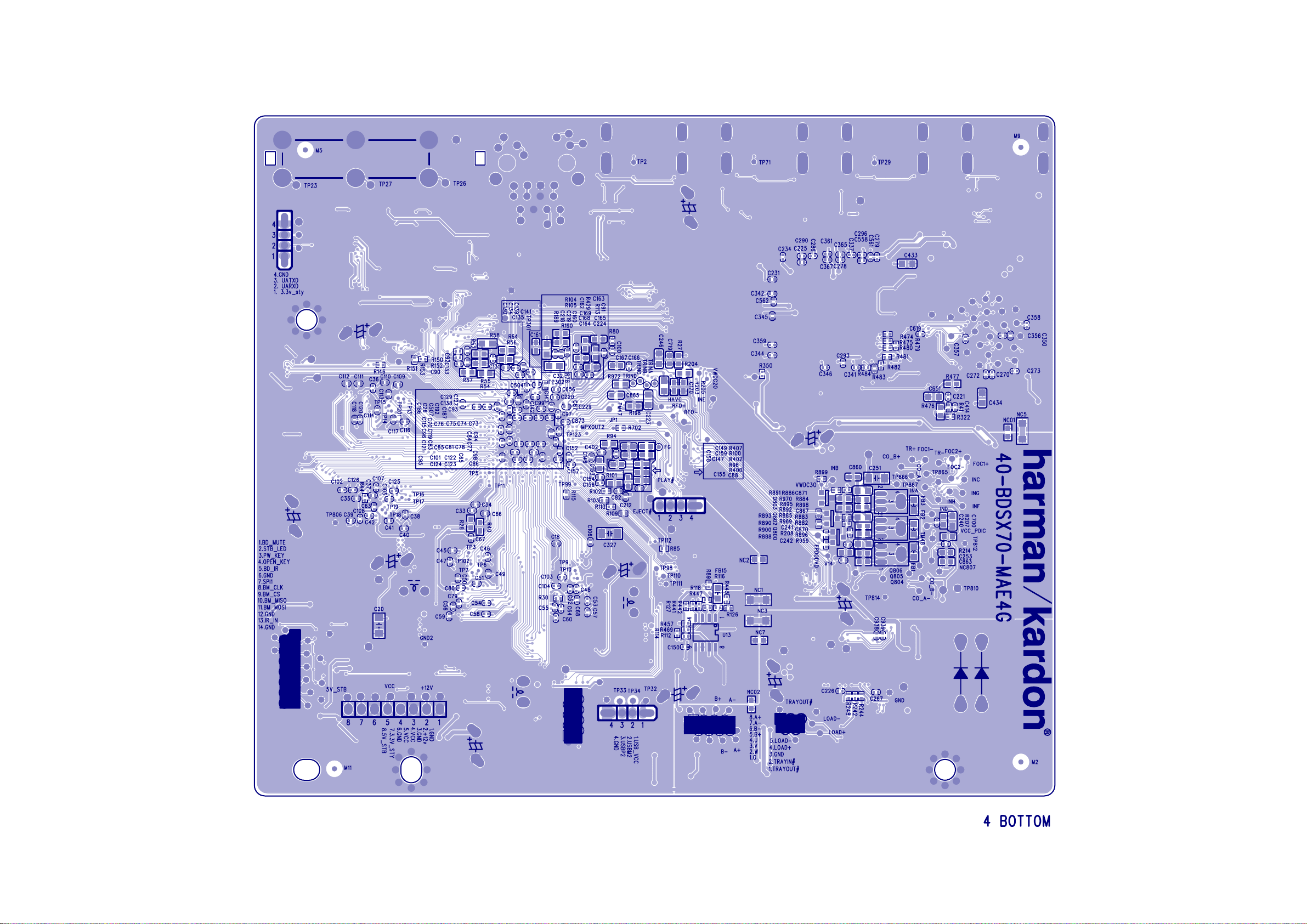
7-33
harman/kardon
BDS 270 + 570 Service Manual
Page 64 of 90
Main Board Print-layout(bottom side):
7-33
Page 65

5
4
3
2 1
D D
C C
B B
A A
6-1 6-1
harman/kardon
BDS 270 + 570 Service Manual
Page 65 of 90
WIRING DIAGRAM
FL+
PWM_P2
FL-
PWM_M7
PWM_P7
FR+ SL+
FR-
LINE_ROUT
LINE_LOUT
13-DRV602-00B
DRV602
L/R PWM
SL/SR PWM
CEN PWM
13-EUP348-2DB
RJ45
TWO LED_CONTROL
HDMI OUTPUT
ETHERNET PHY
1.8V
DC-DC
AT1529
13-AT1529-F11U
FE
MOTOR
+5V
DRIVER
1405B+TP1391
13-TP1391-G4B
13-TPIC14-05B
45P/0.5mm
8P/1.0mm
CEC
DDC
TMDS-OUTPUT
+5V
+12V
ARC+
HPD/ARC-
CEC_A
CEC_B
CEC_C
CEC_D
5P/1.0mm
CEC
Resistor
HDMI 1.4
INPUT-A
PWR5V-A
CEC
13-MT8555-ANBG
TMDS-A
HDMI 1.4
INPUT-B
HPD-A
DDC-A
HDMI
ADV7622
OUTPUT
13-ADV762-20B
Port D
HPD-D
DDC-D
TMDS-D
PWR5V-D
HDMI
OUTPUT
MT8555ANBG
3.3V
FLASH
13-29F2G0-8ABA
NAND FLASH
2Gbit
3V3/0.3A
3V3/0.3A
HPD-B
DDC-B
TMDS-B
PWR5V-B
I2C
DRAM
13-H5TQ1G-63DFR
DDR3x4
+5V
HDMI 1.4
INPUT-C
HPD-C
DDC-C
TMDS-C
PWR5V-C
INT_TX
Port CPort BPort AHDMI output
INT2_RX
INT_RX
CONTROL
RESET
I/O
PD
I2C
Audio
output
VIDEO
INPUT
SPI
USB2
1.15V
1.5V
1.5V
64Mx16x4pcs
3V3/0.6A
+12V
TO MCU
ARC
DE
HS
VS
CLK
VIDEOIN[19:0]
D2+
D2-
USB2
13-AT1529-F11U
I2C
SPDIF_OUT(ARC)
1.15V/2.4A
1.5V/0.6A
DC-DC
AT1529
Pr
ADV7181C
13-ADV718-1CB
VHS
VVS
VDCLK
VIN[19:0]
I2S_OUTPUT
SPI
USB_VCC1
USB_VCC2
13-AT1529-F11U
13-AT1529-F11U
Pb Y
PD
INT
TO MT8555
RESET
I2S_INPUT
SWITCH
G556B1
DC-DC
AT1529
DC-DC
AT1529
7PIN 2.5mm
IR
OPEN_KEY
PW_KEY
STB_LED
BD_MUTE
+5V
14P/1.0mm
1.GND
2.SPDATA
3.AOLRCK
4.BD_MUTE
5.GND
6.AOLRCK
7.AOBCK
8.AOMCK
9.GND
10.SDATA0
11.SDATA1
12.SDATA2
13.SDATA3
14.GND
15.IR1
16.GND
17.SPI1
18.MISO
19.SCLK
20.CS
21.MOSI
22.ARC
23.PW_KEY
24P/0.5mm
24.OPEN_KEY
14P/1.0mm
24P/0.5mm
TUNER
07-KSTS78-00S
LRCK
TUNER_DATA
74LVC541APW
13-74LVC5-41A
3 Wire SPI
I2S_MCLK
TO TI5508
74LVC541APW
13-74LVC5-41A
LRCLK
SCLK
MCLK
DATA0
DATA1
DATA2
DATA3
KEY
IR
LED
MIC/HP
20P/1.0mm
BRIGHE III LIN2
47-BRI001-XX0
IPOD_LROUT
TL072C
13-TL072B-00B
TL072C
13-TL072B-00B
BCK
AD_DATA
AD_MCLK
AKM_DATA
TUNER_DATA
IPOD_IN
AKM5367
AUDIO ADC
AD_MCLK
MUXED_DA
MUXED_LRCLK
MUXED_SCLK
MUXED_DA10
MUXED_DA11
MUXED_DA12
MUXED_DA13
LIN1
RIN1
LR1_IN
MUXED_SCLK
MUXED_LRCLK
LR2_IN
13-AK5367-00B
EN
UART AND DET
3 Wire SPI
5 Wire SPI
3 Wire SPI
POWER_ON
10P/2.0mm 6P/2.5MM
OPTI
OPTI
RIN2
ROUTLOUT
MIC_IN
DAI2
D
A
I
1
CAL1
SPDIF
AD_LRCK
AD_BCK
AD_MCLK
SPDIF_DATA
DAO2
CS495314
13-CS4953-14B
5 Wire SPI
PIC24FJ256GA108
13-P24FJ2-56B
RX2
RX1
CS8422
13-CS8422-00B
DIR_DA
SPD_SCLK
XTAL_DIR
SPD_LRCLK
DAO1
FAN DET AND CONTROL
CAL2
SUBCOAX
RX3
LDO-3.3V
13-S1206S-00B
MUTE
ARC
RX4
64M
SDRAM
8M SPI
FLASH
I2S
I2S_MCLK
IR_IN
SUB
TRIGGER
13-EM6381-6G2B
13-DRV602-00B
DRV602
I2C1
I2C1
DC-DC-3.3V
13-AT1529-F11U
FAN
6P/2.0MM
MIC_IN
HP_ROUT
HP_LOUT
13-TPA611-2A2
TPA6112
SUBWOOFER OUTPUT
HPM_R
HPP_R
HPM_L
HPP_L
PWM_P8
PWM_M8
PWM_M2
AUDIO
PROCESSOR
TI5508
13-TAS550-80B
PDN
MUTE
RESET
/BKND_ERR
/HP_SELO
16K
EEPROM
13-M24C16-MNB
LDO-1.8V DC-DC-8V
13-CW1117-18B
BD BOARD
PDD
PDD
5V
GND
GND
5V
GND
12V
REIC_W
REIC_U
REIC_V
REIC_B-
REIC_COMMON
REIC_B+
REIC_A+
REIC_A-
45P/0.5mm
8P/1.0mm
BD LOADER SANYO414
LOADER
REIC_LOAD+
REIC_LOAD-
5P/1.0mm
SW2
SW1
MGND
GND
USB WIRE
+5V
+5V
GND
+12V
GND
VCC_D
7PIN
20P/1.0mm
IR
VFD DISPLAY
Front Board
OPEN
KEY
POWER
KEY
MIC/HP
VOLUME
6PIN
6PIN
USB
5PIN
12V
GND
12V
5V
5V_STB
5PIN
GND
-12V
VT 5V
POWER_ON
PVCC/10P
5V
12V
-12V
PDD
DGND
DGND
DGND
PVCC/6P
32V
POWER BOARD
SL- SR-
10P/2.0MM
TAS5352
2*65W
13-TAS535-20B
TAS5352
2*65W
13-TAS535-20B
TAS5352
1*65W
13-TAS535-20B
MUTE
SR+
CE+
CE-
AMP BOARD
AC IN
OUTPUT BOARD
10P/2.0MM
SL-
SL+
SR+
FL-
FL+
FR-
FR+
CE-
CE+
SR-
5
4
3
Page 66

A
7-1
harman/kardon
BDS 270 + 570 Service Manual
Page 66 of 90
7-1
5
4
3
2 1
Front Control Board Circuit Diagram: VFD SCH
D D
R657
R657
10K
10K
1
1
2
2
3
3
4
4
5
5
6
6
TO POWER BOARD
TP61TP61
TP62TP62
TP63TP63
TP64TP64
TP66TP66
TP65TP65
LED_1
V5V
R680
R680
330
330
C628
C628
0.1uF
0.1uF
VOL_+
VOL_+
VOL_-
VOL_-
VC3.3V
R682
R682
R683
R681
R681
330
330
LED604LED25BLED604LED25B
LED605LED25BLED605LED25B
R683
330
330
330
330
LED607LED25BLED607LED25B
LED606LED25BLED606LED25B
XP807
XP807
6PIN/2.0mm
6PIN/2.0mm
C C
VC3.3V
R684
R684
10K
10K
R679 330R679 330
R661 330R661 330
ZD603
ZD603
3.3HSA
3.3HSA
C627
C627
100pF
100pF
C626
C626
100pF
100pF
EGND
ZD604
ZD604
3.3HSA
3.3HSA
VR601
VR601
2
VOL+1GND
GND
VOL-
GND
VR_5P
VR_5P
3
4
5
B B
5
4
3
Page 67

7-2 7-2
harman/kardon
BDS 270 + 570 Service Manual
Page 67 of 90
A
Front Control Board Circuit Diagram: VOL
R642 0R642 0
C602
C602
0.01uF/50V/Y5V
P601
P601
JACK_6P_3.5mm
JACK_6P_3.5mm
1 1
R690
R690
68K
68K
R600
R600
47K
47K
2 2
Q615
Q615
MMBT8050C
MMBT8050C
1
7
6
3
2
4
5
12V
C760
C760
1000pF/50V/X7R
1000pF/50V/X7R
R623
R623
10K
10K
XS601
XS601
6PIN/2.0mm
6PIN/2.0mm
TO MAIN PCB
0.01uF/50V/Y5V
TP20TP20
1
7
6
TP22TP22
3
TP23TP23
2
TP21TP21
4
TP68TP68
5
HP_DET
C604
C604
0.1uF
0.1uF
6
6
5
5
4
4
3
3
2
2
1
1
TO MAIN BOARD
1
1
2
2
3
3
4
22
XS603
XS603
5PIN/2.0mm
5PIN/2.0mm
XS807
XS807
6PIN/2.0mm
6PIN/2.0mm
4
5
5
6
6
7
7
8
8
9
9
10
10
11
11
12
12
13
13
14
14
15
15
16
16
17
17
18
18
19
19
20
20
GND21GND
20PIN/0.8mm
20PIN/0.8mm
5
5
4
4
3
3
2
2
1
1
TO POWER BOARD
1
1
2
2
3
3
4
4
5
5
6
6
XP808
XP808
VFD_RST
VT5V
5V
12V
LED_O
5V
TP49TP49
TP56TP56
TP44TP44
TP45TP45
TP46TP46
TP47TP47
TP48TP48
TP50TP50
TP51TP51
TP52TP52
TP53TP53
TO VFD BOARD
TP42TP42
MIC_CT
TP67TP67
TP43TP43
0
R6550R655
TP54TP54
TP55TP55
HP_MUTE
HP_DET
KEY_LED0
3 3
4 4
C601
C601
0.01uF/50V/Y5V
0.01uF/50V/Y5V
HP_DET
PW_KEY
TP24TP24
TP25TP25
TP27TP27
TP28TP28
TP29TP29
TP30TP30
TP31TP31
TP32TP32
TP33TP33
TP34TP34
TP35TP35
TP36TP36
TP37TP37
TP38TP38
TP39TP39
TP40TP40
TP41TP41
RST
VCC3.3V
R607
R607
100K
100K
Q610
Q610
NC/MMBT8050C/NC
NC/MMBT8050C/NC
Q609
Q609
NC/MMBT8050C/NC
NC/MMBT8050C/NC
R652 0R652 0
R608
R608
100K
100K
VCC3.3V
R613 0R613 0
TP26TP26
POWER_control
VCLK_1
VOL+
VOL-
Q617
Q617
S8050C
S8050C
HP_ROUT
HP_LOUT
MIC_OUT
VCC3.3V
VSTB_1
VDIN_1
R612
R612
10K
10K
C629
C629
220pF
220pF
R601 4.7K/NCR601 4.7K/NC
R602 4.7K/NCR602 4.7K/NC
R662
R662
10K
10K
5V
VOL-
VOL+
IR
VSTB_1
OPEN_KEY
PW_KEY
VDIN_1
R620 4.7KR620 4.7K
R698
R698
2.2K
2.2K
R693
R693
4.7K
4.7K
R654
R654
10K
10K
Q613
Q613
PNP_3CG3906M
PNP_3CG3906M
TAC020
TAC020
S602
S602
HP_MUTE
C609
C609
0.047uF
0.047uF
OPEN_KEY
䴴䖥
CE608
CE608
47uF/16V
47uF/16V
470uF/16V
470uF/16V
IC
5V
+
+
CE614
CE614
10uF/16V
10uF/16V
CE601
CE601
470uF/16V
470uF/16V
+
+
R645 0R645 0
B
CE602
CE602
5V
+
+
C625
C625
220pF
220pF
+
+
HP_R
C660
C660
0.1uF
0.1uF
C661
C661
0.1uF
0.1uF
R658
R658
10K
10K
H
㘇ᴎ
L MIC
R644
R644
10K
10K
C662
C662
0.1uF
0.1uF
R669 10KR669 10K
C759
C759
1800pF
1800pF
NPN_3DG3904M
NPN_3DG3904M
TAC020
TAC020
R668
R668
10K
10K
Q620
Q620
MMBT8050C
MMBT8050C
Q619
Q619
MMBT8050C
MMBT8050C
R656 1KR656 1K
Q616
Q616
S603
S603
4
5
6
6
5
4
U22U22
COM
V+
IN
U21
U21
TS5A3159
TS5A3159
IN
V+
COM
R696 NCR696 NC
VCC3.3V
R688
R688
2.2K
2.2K
POWER_control
R695NCR695
NC
NC
GND
NO
NO
GND
NC
MIC_CT
CE607
CE607
47uF/16V
47uF/16V
R653
R653
470
470
3
2
1
1
2
3
12V
+
+
R685 470R685 470
R670 4.7KR670 4.7K
R6340R634
0
C758
C758
0.1uF/50V
0.1uF/50V
R606 20R606 20
VT5V
R626
R626
10K
10K
R660
R660
47K
47K
MMBT8050C
MMBT8050C
Q621
Q621
R671
R671
10K
10K
R625
R625
22K
22K
R641
R641
22K
22K
MIC_IN
R604 20R604 20
R665 56R665 56
HP_ROUT
CE613
CE613
10uF/16V
10uF/16V
HP_LOUT
R686 220R686 220
Q611
Q611
PNP_3CG3906M
PNP_3CG3906M
R6351KR635
1K
Q614
Q614
NPN_3DG3904M
NPN_3DG3904M
D610
D610
1N4007
1N4007
R6722KR672
2K
R689 10KR689 10K
䴴䖥
+
+
+
47uF/16V CE611+47uF/16V CE611
R697 220R697 220
C
IC
C667
C667
0.1uF
0.1uF
Q612
Q612
PNP_3CG3906M
PNP_3CG3906M
R627 2.2KR627 2.2K
C659
C659
0.1uF
0.1uF
R6391KR639
U602
U602
SA555
SA555
R611
R611
4.7K
4.7K
1K
R621
R621
22K
22K
R624
R624
22K
22K
R633 200R633 200
R636
R636
R648 12KR648 12K
V12V
7
8
DA
VCC
GND1TG2OUT3RESET
R687
R687
3.3K
3.3K
Q626
Q626
S8050C
S8050C
330
330
C656
C656
1000pF
1000pF
LED610
LED610
LED03A
LED03A
6
TS
LED1
5V
R659
R659
10K
10K
5V
5
CV
4
V12V
R677 1.2KR677 1.2K
R676 3.3KR676 3.3K
123
C657
C657
1000pF
1000pF
LED611
LED611
LED03A
LED03A
㡆
D
FB15
FB15
FB500/0.5A
FB500/0.5A
12V REFM
47uF/16V
47uF/16V
CE612
CE612
10uF/16V
10uF/16V
+
100pF
100pF
R67368R673
68
Q623
Q623
S8050C
S8050C
D611
D611
1N4148
1N4148
Q622
Q622
S8050C
S8050C
123
C600
C600
0.047uF
0.047uF
㡆
+
NPN_3DG9013H
NPN_3DG9013H
C664
C664
1000pF
1000pF
F+ F-
C665
C665
1000pF
1000pF
R691
R691
2.2K
2.2K
R692
R692
4.7K
4.7K
C658
C658
R664 2KR664 2K
+12V_MIC
CE603
CE603
+
+
R609
R609
100K
100K
VCC3.3V
R640
R640
1.5K
1.5K
VSTB_1 VDINVDIN_1
L601
L601
680uH
680uH
D609
D609
1N4148
1N4148
Q618
Q618
C663
C663
1000pF
1000pF
C666
C666
1000pF
1000pF
D613
D613
1N4148
1N4148
R6101KR610
1K
2SK3018
2SK3018
+
+
CE609
CE609
10uF/50V
10uF/50V
R67468R674
68
D612
D612
1N4148
1N4148
C611
C611
0.1uF
0.1uF
Q601
Q601
D S
S8050C
S8050C
Q624
Q624
R675 3.3KR675 3.3K
S8050C
S8050C
Q625
Q625
R614 27KR614 27K
R617
R617
22K
22K
5V
G
IR1
IR1
IRM_16mm
IRM_16mm
IR
GND
VCC
GND
GND
R666 10R666 10
R678 1.2KR678 1.2K
REFM
R637
R637
2.2K
2.2K
1
2
3
4
5
R667 10R667 10
C605 47pFC605 47pF
R647 10KR647 10K
-
-
2
+
+
3
8 4
+12V_MIC
VCC3.3V
ZD602
ZD602
BZX79C33
BZX79C33
NJM2068V
NJM2068V
R643
R643
4.7K
4.7K
C651
C651
0.1uF
0.1uF
5
6
U603A
U603A
Shell A
Shell B
1
38V
GND
VCC
CE605
CE605
10uF/16V
10uF/16V
R646
R646
1.5K
1.5K
4
3
D+
2
D-
1
USB-A
USB-A
L1 NCL1 NC
+
+
2SK3018
2SK3018
+
+
CE610
CE610
47uF/50V
47uF/50V
P602
P602
R649
R649
Q602
Q602
D S
R615
R615
27K
27K
R618 1KR618 1K
USB5V
A
E
+
+
CE604
CE604
C606
C606
1000pF
1000pF
47uF/16V
47uF/16V
C607
C607
47pF
47pF
10K
10K
R616
R616
NJM2068V
NJM2068V
-
-
U603B
U603B
6
+
+
5
R638
R638
2.2K
2.2K
USB5V
VCLKVCLK_1VSTB
C623
C623
0.1uF
0.1uF
USB_DN
USB_DP
R619
R619
22K
22K
R651
R651
47K
47K
10
USB_DP
REFM
8 4
+12V_MIC
C624
C624
0.1uF
0.1uF
4
ESD1
ESD1
PRTR5V0U2X
PRTR5V0U2X
C608
C608
470pF
470pF
G
IR
100
100
VCC3.3V
R62910R629
5V
C620
C620
0.01uF
0.01uF
A
38V
7
TP57TP57
TP58TP58
TP59TP59
TP60TP60
R663
R663
1.5K
1.5K
VDIN
VSTB
R630 33KR630 33K
R631 10R631 10
23
1
F+
+
10uF/16VCE606+10uF/16VCE606
Q603
Q603
D S
2SK3018
2SK3018
F-
VCLK
USB_DN
RST
R632 10R632 10
MIC_OUT
G
D1
1N4148D11N4148
XS605
XS605
1
2
3
4
4PIN/2.0mm/200mm
4PIN/2.0mm/200mm
26
29
31
32
34
37
40
43
45
46
48
51
R650
R650
2.2K
2.2K
1
2
3
4
R622
R622
100K
100K
U3
1
F-
TSB
TSA
DA
CP
CS
RESET
OSC
VDD
VH
GND
GND
F+
FUTABAU3FUTABA
5V
R6281KR628
1K
RST
C603
C603
0.01uF
0.01uF
A
B
C
D
Page 68

7-3
harman/kardon
BDS 270 + 570 Service Manual
Page 68 of 90
7-3
A
B
C
D E
Inter.Control Board Circuit Diagram:
1 1
XP1
XP1
4PIN/1.0mm
4PIN/1.0mm
sled motor
connector
2 2
6
XP2
XP2
4PIN/1.0mm
4PIN/1.0mm
6
1
1
2
2
3
3
4
4
GND5GND
1
1
2
2
3
3
4
4
GND5GND
U
V
W
COMMON
A+
ABB+
XP4
XP4
8pin/1.0mm
8pin/1.0mm
1
1
2
2
3
3
4
4
5
5
6
6
7
7
8
8
GND9GND
10
AB-
U
V
W
COMMON
A+
B+
3 3
4
A
B
C
Page 69

7-4
harman/kardon
BDS 270 + 570 Service Manual
Page 69 of 90
7-4
A
B
C
D E
BDS270 JACK Output Board Circuit Diagram:
1 1
2 2
XP711
XP711
3.96 PIN
3.96 PIN
Linewidth 2mm
4
4
3
2
1
FL-
3
FL+
2
FR-
1
FR+
5
1
5
1
2
2
L/R SPK JACK
3
4
L/R SPK JACK
3
4
P750
P750
3 3
4
A
B
C
Page 70

7-5
harman/kardon
BDS 270 + 570 Service Manual
Page 70 of 90
7-5
A
Power Supply Board Circuit Diagram:
D501
D501
1N5407/3A/800V
C508
C508
0.22uF/50V/X7R
0.22uF/50V/X7R
C520
C520
C537
C537
0.22uF/50V/X7R
0.22uF/50V/X7R
R58410R584
10
NC12NC
C535
C535
1000pF/50V/X7R
1000pF/50V/X7R
1N5407/3A/800V
BYC10X-600/10A/600V
BYC10X-600/10A/600V
Q501
Q501
DS
G
N_SMK2050CI
N_SMK2050CI
R516 10KR516 10K
R529 0R529 0
U502
U502
SSC2001S
SSC2001S
1
GND
2
Icomp
3
IS
Vins4Vcomp
D510
D510
1N4148
1N4148
R532
R532
2.2M
2.2M
D511 HER108/1A/1000VD511 HER108/1A/1000V
11
10
VGL
COM
RV
8
9
C536
C536
0.22uF/50V/X7R
0.22uF/50V/X7R
FB501
FB501
D502
D502
FB90@100MHz
FB90@100MHz
8
Gate
7
Vcc
6
VFB
5
Q502
Q502
PNP_MMBT8550CLT1
PNP_MMBT8550CLT1
Q503
Q503
PNP_MMBT8550CLT1
PNP_MMBT8550CLT1
R586 680R586 680
R517 0R517 0
C509
C509
1uF/25V/Y5V
1uF/25V/Y5V
C538
C538
10pF/1KV
10pF/1KV
PASPAS
BD501
BD501
1
PASPAS
1 1
NC
RV502
RV502
200V/500A
200V/500A
R506D62R506D
62
R506C62R506C
62
R506B62R506B
62
2 2
R506A62R506A
62
CY506 220pF/250VACCY506220pF/250VAC
3 3
PASPAS
PASPAS
3
KBU610
KBU610
LF502
LF502
2 3
PASPAS
1 4
6.6MH
6.6MH
R503 1MR503 1M
CY501
CY501
220pF/250VAC
220pF/250VAC
R5011MR501
1M
PASPAS
CX502 0.22uF/250VACCX502 0.22uF/250VAC
LF501
LF501
2 3
PASPAS
1 4
6.6MH
6.6MH
PASPAS
CX501 0.33uF/275VACCX501 0.33uF/275VAC
RV501 VDR/560VRV501 VDR/560V
TR501
TR501
NTC/3ohm/5A
NTC/3ohm/5A
2
PASPAS
-+
-+
4
R504 1MR504 1M
CY502
CY502
220pF/250VAC
220pF/250VAC
R5021MR502
PASPAS
CN501
CN501
112
2PIN/7.92mm
2PIN/7.92mm
90V-264V
HV
R5801MR580
1M
R5811MR581
1M
R5821MR582
1M
C530
C530
0.22uF/50V/X7R
0.22uF/50V/X7R
VCC
R583
R583
18K
18K
4 4
2
1M
SSC9512S
SSC9512S
0.1uF/50V/X7R
0.1uF/50V/X7R
R5280R528
0
VCC
C501
C501
1uF/450V
1uF/450V
PASPAS
F501
F501
PASPAS
FUSE_6.3A/250V
FUSE_6.3A/250V
PASPAS
NC
CY505
CY505
1000pF/250VAC
1000pF/250VAC
18
U503
U503
NC
Vsen1VCC2FB3GND4OC6SS5RC7Reg
CE503
CE503
C531
C531
22uF/35V
22uF/35V
CE514
CE514
+
+
4.7uF/16V
4.7uF/16V
R587 47KR587 47K
R530 1MR530 1M
17
NC
+
+
4 10
L501L501
3 9
R514 0.15/2WR514 0.15/2W
R5081MR508
1M
R5091MR509
R515 0.15/2WR515 0.15/2W
1M
R513
R513
R5101MR510
220
220
1M
R511
R511
100K
100K
ZD510
ZD510
R512
R512
MM3Z5V1/5.1V
MM3Z5V1/5.1V
33K
33K
R531 1MR531 1M
16
15
VGH
C533
C533
C532
C532
1000pF/50V/X7R
1000pF/50V/X7R
0.22uF/50V/X7R
0.22uF/50V/X7R
C507
C507
C506
C506
100pF/50V/NP0
100pF/50V/NP0
0.01uF/50V/X7R
0.01uF/50V/X7R
0.47uF/50V/Y5V
0.47uF/50V/Y5V
ZD511
ZD511
MM3Z18/18V
MM3Z18/18V
13
VB14VS
R5851MR585
1M
C534
C534
100pF/50V/NP0
100pF/50V/NP0
R577 680R577 680
CE501
CE501
+
+
100uF/450V
100uF/450V
R51822R518
D503
D503
BAS316/100V/0.5A
BAS316/100V/0.5A
22
R519
R519
47K
47K
C511
C511
C510
C510
1000pF/50V/X7R
1000pF/50V/X7R
0.1uF/50V/X7R
0.1uF/50V/X7R
D512
D512
BAS316/100V/0.5A
BAS316/100V/0.5A
R591 22R591 22
D513
D513
BAS316/100V/0.5A
BAS316/100V/0.5A
R58822R588
22
B
CE502
CE502
+
+
100uF/450V
100uF/450V
R579
R579
100
100
HV
NC
C502
C502
0.01uF/400V
0.01uF/400V
CE513
CE513
C512
C512
+
+
22uF/35V
22uF/35V
0.1uF/50V/X7R
0.1uF/50V/X7R
R592 10R592 10
R589 10R589 10
C539 220pF/1KVC539 220pF/1KV
C
C521
C521
1000pF/1KV
R540 22R540 22
HV
C505
R505A
R505A
R505B
R505B
150K
150K
150K
U501
U501
5
S
6
S
7
S
S8EN/UV
TNY179PN
TNY179PN
Q513
Q513
DS
N_SMK1350F
N_SMK1350F
Q514
Q514
DS
N_SMK1350F
N_SMK1350F
150K
R539
R539
100K
100K
C541
C541
100pF/1KV
100pF/1KV
R5201MR520
1M
R5211MR521
1M
R5221MR522
1M
R5240R524
0
VCC
R523
R523
22K
22K
HV
G
R593
R593
10K
10K
G
R590
R590
10K
10K
C540
C540
0.047uF
0.047uF
R505C
R505C
150K
150K
FR107/1A/1000V
FR107/1A/1000V
Drain
NC
BP/M
R5380R538
0
ZD504
ZD504
BZX79C12
BZX79C12
R505D
150K
150K
D504
D504
4
3
2
R534 150R534 150
1
R535 22KR535 22K
CE505
CE505
+
+
10uF/16V
10uF/16V
4415
2
2
T502
T502
ER39
ER39
R53322R533
22
ZD502
ZD502
D506 FR107/1A/1000VD506 FR107/1A/1000V
Q504
Q504
VCC
NPN_MMBT8050C
NPN_MMBT8050C
R537 1KR537 1K
BZX79C18
BZX79C18
ZD503
ZD503
16
16
15
14
14
13
13
12
12
11
11
10
10
9
9
BZX79C18
BZX79C18
VC1
R53622R536
22
CE504
CE504
+
+
FB1
47uF/35V
47uF/35V
D514
D514
1
3
R20100/20A/100V
R20100/20A/100V
C546
C546
0.1uF/50V/X7R
0.1uF/50V/X7R
D515
D515
1
3
R20100/20A/100V
R20100/20A/100V
C505
2200pF/1KV
2200pF/1KV
R505D
D505
D505
2
2
C529
C529
0.1uF/50V/X7R
0.1uF/50V/X7R
FR107/1A/1000V
FR107/1A/1000V
CY503
CY503
CY504
CY504
T501
T501
6
2
4
1
5
43
CE515
CE515
+
+
820uF/50V
820uF/50V
1.1mH
1.1mH
NC
470pF/250VAC
470pF/250VAC
470pF/250VAC
470pF/250VAC
R552 470R552 470
12
U506
U506
PS2561L1
PS2561L1
43
PASPAS
P
11
10
10
12
8
9
ZD508
ZD508
BZX79C18
BZX79C18
R5941KR594
1K
12
U508
U508
PS2561L1
PS2561L1
U509
U509
AS431
AS431
1000pF/1KV
D507 SR3100/3A/100VD507 SR3100/3A/100V
D509
D509
MBRF1045/10A/45V
MBRF1045/10A/45V
R553
R553
2.2K
2.2K
C525
C525
2
U507
U507
1
AS431
AS431
3
L503 2.9uHL503 2.9uH
CE516
CE516
+
+
820uF/50V
820uF/50V
R571 10m OhmR571 10m Ohm
R5722KR572
P
2K
R595
R595
2.2K
2.2K
C545 0.1uF/50V/X7RC545 0.1uF/50V/X7R
C542 0.1uF/50V/X7RC542 0.1uF/50V/X7R
2
1
3
CE506
CE506
+
+
1000uF/16V
1000uF/16V
2200pF/50V/X7R
2200pF/50V/X7R
CE509
CE509
+
+
1500uF/16V
1500uF/16V
0.1uF/50V/X7R
0.1uF/50V/X7R
R596
R596
R55122R551
C524
C524
22
D
R541 10KR541 10K
D508 FR107/1A/1000VD508 FR107/1A/1000V
L502
L502
3.3uH/3A
3.3uH/3A
CE510
CE510
+
+
1000uF/16V
1000uF/16V
1500uF/16V
1500uF/16V
R554 10KR554 10K
CE517
CE517
C543
C543
+
+
820uF/50V
820uF/50V
0.1uF/50V/X7R
0.1uF/50V/X7R
R573
R573
470K
470K
10K
10K
R599
R599
4.7K/1%
4.7K/1%
CE511
CE511
+
+
R597
R597
56K/1%
56K/1%
OP
R598
R598
4.7K/1%
4.7K/1%
R543
R543
2.2K
2.2K
Q509
Q509
NPN_3DG3904M
NPN_3DG3904M
CE508
CE508
47uF/35V
47uF/35V
R555
R555
12.1K/1%
12.1K/1%
R5570R557
R556
R556
0
11.3K/1%
11.3K/1%
+32V
C571
C571
0.1uF/50V/X7R
0.1uF/50V/X7R
Q508
Q508
PNP_3CG3906M
PNP_3CG3906M
C523 2200pF/50V/X7RC523 2200pF/50V/X7R
R545 2.2KR545 2.2K
Q510
Q510
NPN_3DG3904M
NPN_3DG3904M
R549
R549
100K
100K
+
+
R544
R544
10K
10K
R558 1KR558 1K
Q512
Q512
NPN_3DG3904M
NPN_3DG3904M
+32V
+32V
+32V
GND
GND
GND
LOOP
8
V+
V+
3
+
+
1
2
-
-
V-
V-
<Package>
<Package>
4
LM3580
LM3580
U571A
U571A
R575
R575
P
3
Q505 P_AP6679GIQ505 P_AP6679GI
G
R542
R542
1
10K
10K
12-S
R548 2.2KR548 2.2K
Q507
Q507
NPN_MMBT8050C
NPN_MMBT8050C
R550 22R550 22
+5VSTB
+
+
CE518
CE518
Q511
Q511
10uF/16V
10uF/16V
NPN_3DG3904M
NPN_3DG3904M
D516
D516
MBRX140/40V/1A
MBRX140/40V/1A
VC1
43
U505
U505
PS2561L1
PS2561L1
FB1
R569 22KR569 22K
R568
R568
C526
C526
0.1uF/50V/X7R
0.1uF/50V/X7R
10K
10K
32V/5A
1
1
2
2
3
3
4
4
5
5
6
6
CON504
CON504
6PIN/2.5mm/80mm
6PIN/2.5mm/80mm
R574 10R574 10
C572
C572
0.1uF/50V/X7R
0.1uF/50V/X7R
P
C573
C573
75K/1%
75K/1%
0.1uF/50V/X7R
0.1uF/50V/X7R
D2S
ZD506 BZX79C33ZD506 BZX79C33
2
VIN
1
2
3
12
PCON
R5050R505
0
+5V
CE537
CE537
+
+
22uF/16V
22uF/16V
U504
U504
L79L12ACZ
L79L12ACZ
1
U510
U510
P_PMK50XP
P_PMK50XP
S1
S3
S2
G14D4
R563
R563
470
470
NPN_3DG3904M
NPN_3DG3904M
+5V
R570
R570
1.5K/1%
1.5K/1%
R578
R578
2.21k/1%
2.21k/1%
ZD505
ZD505
BZX79C11
BZX79C11
R546
R546
150
150
R547
R547
200
200
VOUT
GND
D1
D2
D3
R562
R562
470
470
Q515
Q515
TR502
TR502
NTC/10Kohm
NTC/10Kohm
3
8
7
6
5
C544
C544
0.1uF/50V/X7R
0.1uF/50V/X7R
PP PP
CE507
CE507
+
+
470uF/16V
470uF/16V
CE512
CE512
+
+
22uF/35V
22uF/35V
+32V
ZD507
ZD507
BZX79C33
BZX79C33
R564
R564
2.2K
2.2K
R5651KR565
1K
1N4148
1N4148
D572
D572
E
LOOPLOOP
R559
R559
2.21k/1%
2.21k/1%
R606 100KR606 100K
R560
R560
2.21k/1%
2.21k/1%
+12V
R566
R566
22K
22K
R567
R567
10K
10K
-12V
+12V
GND
GND
+5V
+5VSTB
C528
C528
0.1uF/50V/X7R
0.1uF/50V/X7R
C527
C527
0.1uF/50V/X7R
0.1uF/50V/X7R
8
5
+
+
6
-
-
4
5
5
4
4
3
3
2
2
1
1
CON501
CON501
5PIN/2.0mm
5PIN/2.0mm
12-S
R5762.4K/1%R5762.4K/1%
V+
V+
7
V-
V-
<Package>
<Package>
LM3580
LM3580
U571B
U571B
+5VSTB
R5270R527
0
8PIN/2.5mm/200mm
8PIN/2.5mm/200mm
8
+5VSTB
7
PCON
6
GND
5
+5V
4
+5V
3
GND
2
+12V+12V
1
GND
8PIN/2.5mm/200mm
8PIN/2.5mm/200mm
8
+5VSTB+5VSTB
7
GND
6
+5V
+5V
5
+5V
4
GND
3
+12V+12V
2
GND
1
-12V-12V
D573
D573
1N4148
1N4148
CON502
CON502
8
7
6
5
4
3
2
1
CON503
CON503
8
7
6
5
4
3
2
1
OP
A
B
C
D
E
Page 71

A
B
C
D E
7-6
harman/kardon
BDS 270 + 570 Service Manual
Page 71 of 90
7-6
R294
R294
NC/1K
NC/1K
R293
R293
NC/10K
NC/10K
1.1V
R2891KR289
1K
R290
R290
10K
10K
RESET_ 7
+12V
135MA
R296
R296
NC/20K
NC/20K
Q208
Q208
NC/NPN_3DG3904M
NC/NPN_3DG3904M
C301
C301
NC/1uF/25V/Y5V
NC/1uF/25V/Y5V
VCC
Q206
Q206
NPN_3DG3904M
NPN_3DG3904M
C297
C297
1uF/25V/Y5V
1uF/25V/Y5V
R295 NC/100KR295 NC/100K
R291
R291
20K
20K
R292 100KR292 100K
R26
R26
27k
27k
R24 100R24 100
R275
R275
5.1K
5.1K
C313
C313
NC/0.1uF/25V/Y5V
NC/0.1uF/25V/Y5V
C323
C323
0.1uF/25V/Y5V
0.1uF/25V/Y5V
MAE
ࡴ
+12V
VCC
5V_STB
Q209
Q209
G
DS
R963 0R963 0
G
R962 NC/0R962 NC/0
R22
R22
3.3K
3.3K
Q3
Q3
NPN_3DG3904M
NPN_3DG3904M
A03407
NC/P_A03407
NC/P_A03407
Q207
Q207
P_ASM3403
P_ASM3403
DS
89MA FOR BD
C316
C316
0.1uF/25V/Y5V
0.1uF/25V/Y5V
125MA FOR bd
C299
C299
0.1uF/25V/Y5V
0.1uF/25V/Y5V
R276
R276
R277
R277
100
100
100
100
Q4
Q4
NPN_3DG9013
NPN_3DG9013
+12V_D
VCC_D
VCC
C4
C4
0.1uF/25V/Y5V
0.1uF/25V/Y5V
C3
C3
0.1uF/25V/Y5V
R1 10R1 10
OPWRSB
OPWRSB7
R200
R200
4.7K
4.7K
R3 100R3 100
5V_STB
C324
C324
0.1uF/50V/X7R
0.1uF/50V/X7R
0.1uF/25V/Y5V
U1
1
VCC
5
EN
3
GND
R5
9
10KR510K
TP
AT1529U1AT1529
PGND
8
VIN
7
LX
4
1.1V_FB
FB
2
REF
6
Close to DC-DC
C5
C5
10uF/10V/Y5V
10uF/10V/Y5V
L1 2.2uH/3AL1 2.2uH/3A
DC Current: 4.1A
Saturation Current: 6.4A
DC resistor: 15mOHM
C325
C325
0.1uF/25V/Y5V
0.1uF/25V/Y5V
(pin to pin with G5627) ৠℹ 3.2A
EN
VCC
R306 2.2KR306 2.2K
VCC
(pin to pin with G5627) ৠℹ 3.2A
C391
C393
C393
0.1uF/25V/Y5V
0.1uF/25V/Y5V
C391
0.1uF/25V/Y5V
0.1uF/25V/Y5V
R307
R307
10K
10K
R39 10R39 10
(pin to pin with G5627) ৠℹ 3.2A
U6
1
VCC
5
EN
3
GND
9
TP
AT1526U6AT1526
PGND
8
VIN
7
LX
4
FB
2
REF
6
R8 10R8 10
C29
C29
0.1uF/25V/Y5V
0.1uF/25V/Y5V
C30
C30
0.1uF/25V/Y5V
0.1uF/25V/Y5V
EN
R571
R571
20K
20K
᳝ⳕ⬉ᓣ
C395
C395
0.1uF/25V/Y5V
U15
U15
1
VCC
5
EN
3
GND
9
TP
AT1526
AT1526
PGND
8
VIN
7
LX
4
FB
2
REF
6
0.1uF/25V/Y5V
C459 10uF/10V/Y5VC459 10uF/10V/Y5V
L4 2.2uH/3AL4 2.2uH/3A
C394
C394
0.1uF/25V/Y5V
0.1uF/25V/Y5V
1.1V
C43
C43
0.1uF/25V/Y5V
0.1uF/25V/Y5V
C11 10uF/10V/Y5VC11 10uF/10V/Y5V
L3 2.2uH/3AL3 2.2uH/3A
C45
C45
0.1uF/25V/Y5V
0.1uF/25V/Y5V
behind of Caps
C392
C392
22uF/10V/Y5V
22uF/10V/Y5V
behind of Caps
2A FOR 2D BD
R6
1.2K/1%R61.2K/1%
C8
C8
R2
22uF/10V/Y5V
22uF/10V/Y5V
1.1V_FB
AIM 1.15V: 0.8*(6.65+15)/15=1.155V
AIM 1.2V: 0.8*(7.87+15)/15=1.22V
5.6K/1%R25.6K/1%
R4
15K/1%R415K/1%
C326
C326
0.1uF/25V/Y5V
0.1uF/25V/Y5V
᳝ⳕ⬉ᓣ
᳝ⳕ⬉ᓣ
behind of Caps
R928
R928
560
560
C20
C20
22uF/10V/Y5V
22uF/10V/Y5V
R4
13K/1%R413K/1%
R5
15K/1%R515K/1%
max 0.5A+0.31A+0.3A
R465
R465
1.8k
1.8k
R466
R466
30K
30K
R467
R467
10K/1%
10K/1%
C9
C9
0.1uF/25V/Y5V
0.1uF/25V/Y5V
C388
C388
22uF/10V/Y5V
22uF/10V/Y5V
1.2V
3.3V
R25 0R25 0
557MA
C2
C2
0.1uF/25V/Y5V
0.1uF/25V/Y5V
FB23
FB23
FB18 10/2AFB18 10/2A
C389
C389
0.1uF/25V/Y5V
0.1uF/25V/Y5V
A1.2V
10/2A
10/2A
1.1V
POWER
1.1V
C327
C327
22uF/10V/Y5V
22uF/10V/Y5V
C14
C14
22uF/10V/Y5V
22uF/10V/Y5V
V3.3V
Max 0.5A
CE6
CE6
+
+
100uF/16V
100uF/16V
1.5V
310mA
1.2A
C46
C46
0.1uF/25V/Y5V
0.1uF/25V/Y5V
A3.3V
C22
C22
0.1uF/25V/Y5V
0.1uF/25V/Y5V
CE205
CE205
+
+
470uF/6.3V
470uF/6.3V
Main Board Circuit Diagram:POWER
GND1GND1
XP3
XP3
8
8
7
7
8PIN/2.5mm
8PIN/2.5mm
GND2GND2
6
6
5
5
4
4
3
3
2
2
1
1
C298
C298
100pF/50V/NP0
100pF/50V/NP0
4 4
3 3
TM64TM64
VCCVCC
+12V+12V
R299 1KR299 1K
C321
C321
C318
C318
100pF/50V/NP0
100pF/50V/NP0
5V_STB
100pF/50V/NP0
100pF/50V/NP0
5V_STB5V_STB
C355
C355
OPWRSB
1.57A FOR BD
135MA FOR BD
100pF/50V/NP0
100pF/50V/NP0
1.1V
VCC
+12V
Internal MCU Use U2
3.3V
External MCU Use R7
R7 NC/0R7 NC/0
U2
5V_STB
close to DC/DC
C11
C11
2.2uF/10V/Y5V
2.2uF/10V/Y5V
2 2
VCC R/R to Q3.b
5.000V 0.772V
4.532V 0.700V
3.885V 0.600V
3.237V 0.500V
R300
R300
15K/1%
15K/1%
R301 100R301 100
R302
R302
2.7K
2.7K
5V_STB 3.3V_STBY
R303
R303
3.3K
3.3K
Q5
Q5
NPN_3DG3904M
NPN_3DG3904M
U2
1
VIN
2
GND
EN3NC
LDO_G9091-330T11U
LDO_G9091-330T11U
R304
R304
NC/33K
NC/33K
5
VOUT
close to LDO
4
C
1
2N3904
R305
R305
20K
20K
Q6
Q6
NPN_3DG3904M
NPN_3DG3904M
2
EB
3
R15
R15
NC/100K
NC/100K
C12
C12
4.7uF/16V/Y5V
4.7uF/16V/Y5V
RESET#
C25
C25
10uF/10V/Y5V
10uF/10V/Y5V
3.3V_STBY
100MA(Max)
146MA
RESET
CIRCUIT
TP1TP1
0.1uF/25V/Y5V
0.1uF/25V/Y5V
C26
C26
close to IC
58MA(BD)
1
VCC_D
R21
R20
R20
15K/1%
15K/1%
R23 100R23 100
R19
R19
2.7K
2.7K
䆑
AC power offǂǂRSTIȦVCORE 1.1V
R21
3.3K
3.3K
Q1
Q1
NPN_3DG3904M
NPN_3DG3904M
A
R20
R20
10K
10K
Q2
Q2
NPN_3DG3904M
NPN_3DG3904M
C7
C7
0.1uF/25V/Y5V
0.1uF/25V/Y5V
ǂ༨
C41
C41
0.1uF/25V/Y5V
0.1uF/25V/Y5V
EN
EN 9
B
C
Page 72

A
B
C
D
E
7-7
harman/kardon
BDS 270 + 570 Service Manual
Page 72 of 90
7-7
1.2V
R101 0R101 0
4 4
1.5V
C105
C105
0.1uF/16V/X7R
0.1uF/16V/X7R
1.5V
C110
C110
0.1uF/16V/X7R
0.1uF/16V/X7R
3 3
1.5V
C114
C114
0.1uF/16V/X7R
0.1uF/16V/X7R
1.5V
C119
C119
0.1uF/16V/X7R
0.1uF/16V/X7R
1.5V
C57
C57
0.1uF/16V/X7R
0.1uF/16V/X7R
2 2
1 1
C101NCC101
NC
C38
C38
0.1uF/16V/X7R
0.1uF/16V/X7R
C111
C111
0.1uF/16V/X7R
0.1uF/16V/X7R
C115
C115
0.1uF/16V/X7R
0.1uF/16V/X7R
C120
C120
0.1uF/16V/X7R
0.1uF/16V/X7R
C125
C125
0.1uF/16V/X7R
0.1uF/16V/X7R
AVDD12_MEMPLL
C102
C102
0.1uF/16V/Y5V
0.1uF/16V/Y5V
TP
TP
C39
C39
0.1uF/16V/X7R
0.1uF/16V/X7R
C44
C44
0.1uF/16V/X7R
0.1uF/16V/X7R
C116
C116
0.1uF/16V/X7R
0.1uF/16V/X7R
C121
C121
0.1uF/16V/X7R
0.1uF/16V/X7R
C126
C126
0.1uF/16V/X7R
0.1uF/16V/X7R
TP100TPTP100
TP101TPTP101
C108
C108
0.1uF/16V/X7R
0.1uF/16V/X7R
C113
C113
0.1uF/16V/X7R
0.1uF/16V/X7R
C117
C117
0.1uF/16V/X7R
0.1uF/16V/X7R
C122
C122
0.1uF/16V/X7R
0.1uF/16V/X7R
C127
C127
0.1uF/16V/X7R
0.1uF/16V/X7R
Main Board Circuit Diagram:MT8555.DDR Part1
1.5V
C109
C109
0.1uF/16V/X7R
0.1uF/16V/X7R
C100
C100
0.1uF/16V/X7R
0.1uF/16V/X7R
C118
C118
0.1uF/16V/X7R
0.1uF/16V/X7R
C123
C123
0.1uF/16V/X7R
0.1uF/16V/X7R
C128
C128
0.1uF/16V/X7R
0.1uF/16V/X7R
AVDD12_MEMPLL
TP_MEMPLL
TN_MEMPLL
AA25
AE10
AF14
AE17
AF20
AG26
AF13
AA13
AA15
AA19
AA11
AA17
AE23
AD23
AE24
AF24
AA26
AA12
AA14
W11
W13
W15
W17
AF10
AE20
AF17
AE14
AA16
AF26
AB11
W19
W21
AA18
P26
V26
R25
V21
P21
M21
M10
K10
N11
P10
R11
U11
M12
M13
M14
M15
M17
V10
N12
N13
N14
N15
N16
P12
P13
P14
P15
P17
K12
R12
R13
R14
R15
R16
V12
U12
U14
U16
U13
K14
V14
U15
K16
M16
P16
V16
N17
R17
U17
K18
M18
P18
V18
N19
R19
U19
N25
V25
R26
M11
U21
N21
R21
T21
Y20
L11
L13
L15
T10
T13
T15
T17
T12
T14
T16
L17
T18
L19
W9
U9
L21
N9
U7A
U7A
DVCC18_IO_1
DVCC18_IO_1
DVCC18_IO_1
DVCC18_IO_1
DVCC18_IO_1
DVCC18_IO_1
DVCC18_IO_1
DVCC18_IO_1
DVCC18_IO_1
DVCC18_IO_1
DVCC18_IO_1
DVCC18_IO_1
DVCC18_IO_1
DVCC18_IO_1
DVCC18_IO_1
DVCC18_IO_1
DVCC18_IO_1
DVCC18_IO_1
DVCC18_IO_1
DVCC18_IO_1
AVDD12_MEMPLL
AVSS12_MEMPLL
TP_MEMPLL
TN_MEMPLL
DGND
DGND
DGND
DGND
DGND
DGND
DGND
DGND
DGND
DGND
DGND
DGND
DGND
DGND
DGND
DGND
DGND
DGND
DGND
DGND
DGND
DGND
DGND
DGND
DGND
DGND
DGND
DGND
DGND
DGND
DGND
DGND
DGND
DGND
DGND
DGND
DGND
DGND
DGND
DGND
DGND
DGND
DGND
DGND
DGND
DGND
DGND
DGND
DGND
DGND
DGND
DGND
DGND
DGND
DGND
DGND
DGND
DGND
DGND
DGND
DGND
DGND
DGND
DGND
DGND
DGND
DGND
DGND
DGND
DGND
DGND
DGND
DGND
DGND
DGND
DGND
DGND
DGND
DGND
DGND
DGND
DGND
DGND
DGND
DGND
DGND
DGND
DGND
DGND
DGND
DGND
MT8555_0825_A
MT8555_0825_A
RDQ0
RDQ1
RDQ2
RDQ3
RDQ4
RDQ5
RDQ6
RDQ7
RDQ8
RDQ9
RDQ10
RDQ11
RDQ12
RDQ13
RDQ14
RDQ15
RDQ16
RDQ17
RDQ18
RDQ19
RDQ20
RDQ21
RDQ22
RDQ23
RDQ24
RDQ25
RDQ26
RDQ27
RDQ28
RDQ29
RDQ30
RDQ31
RDQM0
RDQM1
RDQM2
RDQM3
RDQS0
RDQS0_
RDQS1
RDQS1_
RDQS2
RDQS2_
RDQS3
RDQS3_
RODT
RCAS_
RRAS_
RCS_
RWE_
RCKE
RRESET
RBA0
RBA1
RBA2
RA10
RA11
RA12
RA13
RCLK0
RCLK0_
RCLK1
RCLK1_
RVREF_1
RVREF_2
RA0
RA1
RA2
RA3
RA4
RA5
RA6
RA7
RA8
RA9
AG17
AF18
AE18
AF19
AC22
AF23
AF22
AG22
AH19
AG19
AC20
AD20
AE22
AH22
AD22
AF21
AG7
AH7
AH8
AG8
AF12
AE12
AC12
AD12
AE8
AF8
AE9
AF9
AH11
AG11
AF11
AE11
AE21
AD21
AD10
AD9
AG20
AH20
AH21
AG21
AG9
AH9
AH10
AG10
AC14
AD14
AC13
AE15
AE13
AG16
AC16
AG14
AD19
AC15
AD13
AE19
AF16
AH14
AD18
AD15
AC17
AE16
AH16
AF15
AH17
AD17
AC18
AD16
AG24
AH24
AG13
AH13
AB12
AA20
A_DQ0
A_DQ1
A_DQ2
A_DQ3
A_DQ4
A_DQ5
A_DQ6
A_DQ7
A_DQ8
A_DQ9
A_DQ10
A_DQ11
A_DQ12
A_DQ13
A_DQ14
A_DQ15
A_DQ16
A_DQ17
A_DQ18
A_DQ19
A_DQ20
A_DQ21
A_DQ22
A_DQ23
A_DQ24
A_DQ25
A_DQ26
A_DQ27
A_DQ28
A_DQ29
A_DQ30
A_DQ31
A_DQM0
A_DQM1
A_DQM2
A_DQM3
A_DQS0
A_DQS0#
A_DQS1
A_DQS1#
A_DQS2
A_DQS2#
A_DQS3
A_DQS3#
A_ODT
A_CAS#
A_RAS#
A_CS#
A_WE#
A_CKE
A_RRESET#
A_BA0
A_BA1
A_BA2
A_RA0
A_RA1
A_RA2
A_RA3
A_RA4
A_RA5
A_RA6
A_RA7
A_RA8
A_RA9
A_RA10
A_RA11
A_RA12
A_RA13
A_CLK0
A_CLK0#
A_CLK1
A_CLK1#
DDRIC_VREF
C132
C132
0.1uF/16V/X7R
0.1uF/16V/X7R
R40 0R40 0
DDR_VREF
DDRIC_VREF
C133
C133
0.1uF/16V/X7R
0.1uF/16V/X7R
DDR_VREF
C35
C35
0.1uF/25V/Y5V
0.1uF/25V/Y5V
C134
C134
0.1uF/25V/Y5V
0.1uF/25V/Y5V
DDR_VREF
U102
U101
U101
E3
DQ0
F7
DQ1
F2
DQ2
F8
DQ3
H3
DQ4
H8
DQ5
G2
DQ6
H7
DQ7
D7
DQ8
C3
DQ9
C8
DQ10
C2
DQ11
A7
DQ12
A2
DQ13
B8
DQ14
A3
DQ15
C7
UDQS
B7
UDQS#
F3
LDQS
G3
LDQS#
D3
UDM
E7
LDM
H1
VREFDQ
M8
VREFCA
T2
RESET#
L8
ZQ
1.5V 1.5V
A1
VDDQ_0
A8
VDDQ_1
C1
VDDQ_2
C9
VDDQ_3
D2
VDDQ_4
E9
VDDQ_5
F1
VDDQ_6
H2
VDDQ_7
H9
VDDQ_8
B2
VDD_0
D9
VDD_1
G7
VDD_2
K2
VDD_3
K8
VDD_4
N1
VDD_5
N9
VDD_6
R9
VDD_8
R1
VDD_7
128Mx16 DDR3-1333 SDRM
128Mx16 DDR3-1333 SDRM
R102
R102
240
240
A_DQ3
A_DQ7
A_DQ1
A_DQ6
A_DQ0
A_DQ5
A_DQ2
A_DQ4
A_DQ15
A_DQ11
A_DQ12
A_DQ9
A_DQ13
A_DQ8
A_DQ14
A_DQ10
A_DQS1
A_DQS1#
A_DQS0
A_DQS0#
A_DQM1
A_DQM0
A_RRESET#
A10/AP
A11
A12/BC#
A13
NC_0
NC_1
NC_2
NC_3
NC_4
NC_6
BA0
BA1
BA2
CK#
CS#
CAS#
ODT
RAS#
WE#
CKE
VSSQ_0
VSSQ_1
VSSQ_2
VSSQ_3
VSSQ_4
VSSQ_5
VSSQ_6
VSSQ_7
VSSQ_8
VSS_0
VSS_1
VSS_2
VSS_3
VSS_4
VSS_5
VSS_6
VSS_7
VSS_8
VSS_9
VSS_10
VSS_11
N3
A0
A1
A2
A3
A4
A5
A6
A7
A8
A9
CK
A_RA0
P7
A_RA1
P3
A_RA2
N2
A_RA3
P8
A_RA4
P2
A_RA5
R8
A_RA6
R2
A_RA7
T8
A_RA8
R3
A_RA9
L7
A_RA10
R7
A_RA11
N7
A_RA12
T3
A_RA13
J1
J9
L1
L9
M7
T7
M2
A_BA0
N8
A_BA1
M3
A_BA2
J7
D_CLK0
K7
D_CLK0#
L2
A_CS#
K3
A_CAS#
K1
A_ODT
J3
A_RAS#
L3
A_WE#
K9
A_CKE
B1
B9
D1
D8
E2
E8
F9
G1
G9
A9
B3
E1
G8
J2
J8
M1
M9
P1
P9
T1
T9
DDR_VREF
C104
C104
0.1uF/25V/Y5V
0.1uF/25V/Y5V
A_DQ18
A_DQ23
A_DQ19
A_DQ21
A_DQ16
A_DQ20
A_DQ17
A_DQ22
A_DQ29
A_DQ26
A_DQ31
A_DQ27
A_DQ28
A_DQ24
A_DQ30
A_DQ25
A_DQS3
A_DQS3#
A_DQS2
A_DQS2#
A_DQM3
A_DQM2
A_RRESET#_2R
R100
R100
240
240
U102
E3
DQ0
F7
DQ1
F2
DQ2
F8
DQ3
H3
DQ4
H8
DQ5
G2
DQ6
H7
DQ7
D7
DQ8
C3
DQ9
C8
DQ10
C2
A7
A2
B8
A3
C7
B7
F3
G3
D3
E7
H1
M8
T2
L8
A1
A8
C1
C9
D2
E9
F1
H2
H9
B2
D9
G7
K2
K8
N1
N9
R9
R1
A10/AP
DQ11
DQ12
A12/BC#
DQ13
DQ14
DQ15
UDQS
UDQS#
LDQS
LDQS#
UDM
LDM
VREFDQ
VREFCA
RESET#
ZQ
VSSQ_0
VSSQ_1
VSSQ_2
VDDQ_0
VSSQ_3
VDDQ_1
VSSQ_4
VDDQ_2
VSSQ_5
VDDQ_3
VSSQ_6
VDDQ_4
VSSQ_7
VDDQ_5
VSSQ_8
VDDQ_6
VSS_0
VDDQ_7
VSS_1
VDDQ_8
VSS_2
VDD_0
VSS_3
VDD_1
VSS_4
VSS_5
VDD_2
VDD_3
VSS_6
VDD_4
VSS_7
VDD_5
VSS_8
VSS_9
VDD_6
VSS_10
VDD_8
VSS_11
VDD_7
128Mx16 DDR3-1333 SDRM
128Mx16 DDR3-1333 SDRM
NC_0
NC_1
NC_2
NC_3
NC_4
NC_6
CK#
CS#
CAS#
ODT
RAS#
WE#
CKE
N3
A0
P7
A1
P3
A2
N2
A3
P8
A4
P2
A5
R8
A6
R2
A7
T8
A8
R3
A9
L7
R7
A11
N7
T3
A13
J1
J9
L1
L9
M7
T7
M2
BA0
N8
BA1
M3
BA2
J7
CK
K7
L2
K3
K1
J3
L3
K9
B1
B9
D1
D8
E2
E8
F9
G1
G9
A9
B3
E1
G8
J2
J8
M1
M9
P1
P9
T1
T9
NEAR 8555 NEAR 8555NEAR DRAM NEAR DRAM
A_CLK0#
A_CLK0
C135
C135
0.1uF/25V/Y5V
0.1uF/25V/Y5V
R103 0R103 0
R107 0R107 0
R105
R105
100/1%
100/1%
D_CLK0#
D_CLK0
A_RA2
A_RA0
A_BA2
A_WE#
A_CS#
A_BA0
A_RA3
A_RA5
A_RAS#
A_ODT
A_CAS#
A_RA13
A_RRESET#
A_RA9
A_RA7
A_CKE
A_RA10
A_BA1
A_RA12
A_RA4
A_RA1
A_RA6
A_RA8
A_CLK1# D_CLK1#
R104 0R104 0
R108 0R108 0
RN100
RN100
1
8
2
7
3
6
4
5
0*4
0*4
1
8
RN101 0*4RN101 0*4
RN102 0*4RN102 0*4
RN103 0*4RN103 0*4
RN104 0*4RN104 0*4
RN105 0*4RN105 0*4
7
6
5
8
7
6
5
8
7
6
5
8
7
6
5
8
7
6
5
R114 0R114 0
2
3
4
1
2
3
4
1
2
3
4
1
2
3
4
1
2
3
4
R34
R34
100/1%
100/1%
A_RA2_2R
A_RA0_2R
A_BA2_2R
A_WE#_2R
A_CS#_2R
A_BA0_2R
A_RA3_2R
A_RA5_2R
A_RAS#_2R
A_ODT_2R
A_CAS#_2R
A_RA13_2R
A_RRESET#_2R
A_RA9_2R
A_RA7_2R
A_CKE_2R
A_RA10_2R
A_BA1_2R
A_RA12_2R
A_RA4_2R
A_RA1_2R
A_RA6_2R
A_RA8_2R
A_RA11_2RA_RA11
A_RA0_2R
A_RA1_2R
A_RA2_2R
A_RA3_2R
A_RA4_2R
A_RA5_2R
A_RA6_2R
A_RA7_2R
A_RA8_2R
A_RA9_2R
A_RA10_2R
A_RA11_2R
A_RA12_2R
A_RA13_2R
A_BA0_2R
A_BA1_2R
A_BA2_2R
D_CLK1
D_CLK1#
A_CS#_2R
A_CAS#_2R
A_ODT_2R
A_RAS#_2R
A_WE#_2R
A_CKE_2R
D_CLK1A_CLK1
1.5V
R109
C62
C62
0.1uF/25V/Y5V
0.1uF/25V/Y5V
C63
C63
0.1uF/25V/Y5V
0.1uF/25V/Y5V
R109
100
100
R110
R110
100
100
DDR_VREF
A_DQS1
A_DQS1#
A_DQS0
A_DQS0#
A_DQS3
A_DQS3#
A_DQS2
A_DQS2#
DDR_VREF
C131
C131
0.1uF/25V/Y5V
0.1uF/25V/Y5V
TP102TPTP102
TP103TPTP103
TP104TPTP104
TP105TPTP105
TP106TPTP106
TP107TPTP107
TP108TPTP108
TP109TPTP109
TP
TP
TP
TP
TP
TP
TP
TP
A
B
C
D
E
Page 73

E
7-8
harman/kardon
BDS 270 + 570 Service Manual
Page 73 of 90
7-8
A
Main Board Circuit Diagram:MT8555.DDR Part2
1.1V
C204
C201
C201
0.1uF/16V/X7R
0.1uF/16V/X7R
4 4
1.1V
C207
C207
0.1uF/16V/X7R
0.1uF/16V/X7R
1.1V
C216
C216
0.1uF/16V/X7R
0.1uF/16V/X7R
3 3
2 2
1.5V
C242
C242
0.1uF/16V/X7R
0.1uF/16V/X7R
1.5V
C248
C248
0.1uF/16V/X7R
0.1uF/16V/X7R
1.5V
1 1
C202
C202
0.1uF/16V/X7R
0.1uF/16V/X7R
C205
C205
0.1uF/16V/X7R
0.1uF/16V/X7R
C217
C217
0.1uF/16V/X7R
0.1uF/16V/X7R
C243
C243
0.1uF/16V/X7R
0.1uF/16V/X7R
C249
C249
0.1uF/16V/X7R
0.1uF/16V/X7R
C212
C212
0.1uF/16V/X7R
0.1uF/16V/X7R
C206
C206
0.1uF/16V/X7R
0.1uF/16V/X7R
C218
C218
0.1uF/16V/X7R
0.1uF/16V/X7R
C244
C244
0.1uF/25V/Y5V
0.1uF/25V/Y5V
C250
C250
0.1uF/16V/X7R
0.1uF/16V/X7R
C203
C203
0.1uF/16V/X7R
0.1uF/16V/X7R
C213
C213
0.1uF/16V/X7R
0.1uF/16V/X7R
C84
C84
1000pF/50V/X7R
1000pF/50V/X7R
C245
C245
0.1uF/25V/Y5V
0.1uF/25V/Y5V
C251
C251
0.1uF/16V/X7R
0.1uF/16V/X7R
C204
0.1uF/16V/X7R
0.1uF/16V/X7R
C208
C208
0.1uF/16V/X7R
0.1uF/16V/X7R
C220
C220
0.1uF/16V/X7R
0.1uF/16V/X7R
C246
C246
0.1uF/16V/X7R
0.1uF/16V/X7R
C111
C111
0.1uF/16V/X7R
0.1uF/16V/X7R
1.1V
C247
C247
0.1uF/16V/X7R
0.1uF/16V/X7R
C252
C252
0.1uF/16V/X7R
0.1uF/16V/X7R
1.5V
CE3
CE3
+
+
220uF/16V
220uF/16V
L10
W18
M9
W10
P11
V9
M19
N10
T11
P19
R10
V11
K11
L12
T19
K13
V13
K15
L14
U10
K17
V15
L16
K19
V17
V19
L18
N18
R18
U18
W12
W14
W16
C253
C253
0.1uF/16V/X7R
0.1uF/16V/X7R
B
U7B
U7B
DVCC10_K
DVCC10_K
DVCC10_K
DVCC10_K
DVCC10_K
DVCC10_K
DVCC10_K
DVCC10_K
DVCC10_K
DVCC10_K
DVCC10_K
DVCC10_K
DVCC10_K
DVCC10_K
DVCC10_K
DVCC10_K
DVCC10_K
DVCC10_K
DVCC10_K
DVCC10_K
DVCC10_K
DVCC10_K
DVCC10_K
DVCC10_K
DVCC10_K
DVCC10_K
DVCC10_K
DVCC10_K
DVCC10_K
DVCC10_K
DVCC10_K
DVCC10_K
DVCC10_K
MT8555_0825_A
MT8555_0825_A
RDQ0_B
RDQ1_B
RDQ2_B
RDQ3_B
RDQ4_B
RDQ5_B
RDQ6_B
RDQ7_B
RDQ8_B
RDQ9_B
RDQ10_B
RDQ11_B
RDQ12_B
RDQ13_B
RDQ14_B
RDQ15_B
RDQ16_B
RDQ17_B
RDQ18_B
RDQ19_B
RDQ20_B
RDQ21_B
RDQ22_B
RDQ23_B
RDQ24_B
RDQ25_B
RDQ26_B
RDQ27_B
RDQ28_B
RDQ29_B
RDQ30_B
RDQ31_B
RDQM0_B
RDQM1_B
RDQM2_B
RDQM3_B
RDQS0_B
RDQS0__B
RDQS1_B
RDQS1__B
RDQS2_B
RDQS2__B
RDQS3_B
RDQS3__B
RODT_B
RCAS__B
RRAS__B
RCS__B
RWE__B
RCKE_B
RRESET_B
RBA0_B
RBA1_B
RBA2_B
RA0_B
RA1_B
RA2_B
RA3_B
RA4_B
RA5_B
RA6_B
RA7_B
RA8_B
RA9_B
RA10_B
RA11_B
RA12_B
RA13_B
RCLK0_B
RCLK0__B
RCLK1_B
RCLK1__B
RVREF_3
RVREF_4
C254
C254
0.1uF/16V/X7R
0.1uF/16V/X7R
T25
T26
U26
U25
M26
M25
N28
N27
P23
T28
T27
T23
N26
P24
N23
N24
AF25
AG25
AH25
AH26
AA24
AB24
AA23
AB23
AD25
AE25
AH27
AH28
AC25
AD24
AC24
AC23
P25
R24
AD26
AE26
R27
R28
P28
P27
AG27
AG28
AF28
AF27
AD27
AC26
AD28
AB25
AE28
V27
Y26
B_RRESET#
AB26
T24
W25
AE27
U24
W28
AA27
V24
AA28
W24
W27
Y24
W26
V28
V23
U23
Y25
L27
L28
AB27
AB28
AA21
DDRIC_VREF
R23
C255
C255
0.1uF/16V/X7R
0.1uF/16V/X7R
B_DQ0
B_DQ1
B_DQ2
B_DQ3
B_DQ4
B_DQ5
B_DQ6
B_DQ7
B_DQ8
B_DQ9
B_DQ10
B_DQ11
B_DQ12
B_DQ13
B_DQ14
B_DQ15
B_DQ16
B_DQ17
B_DQ18
B_DQ19
B_DQ20
B_DQ21
B_DQ22
B_DQ23
B_DQ24
B_DQ25
B_DQ26
B_DQ27
B_DQ28
B_DQ29
B_DQ30
B_DQ31
B_DQM0
B_DQM1
B_DQM2
B_DQM3
B_DQS0
B_DQS0#
B_DQS1
B_DQS1#
B_DQS2
B_DQS2#
B_DQS3
B_DQS3#
B_ODT
B_CAS#
B_RAS#
B_CS#
B_WE#
B_CKE
B_BA0
B_BA1
B_BA2
B_RA0
B_RA1
B_RA2
B_RA3
B_RA4
B_RA5
B_RA6
B_RA7
B_RA8
B_RA9
B_RA10
B_RA11
B_RA12
B_RA13
B_CLK0
B_CLK0#
B_CLK1
B_CLK1#
C232
C232
0.1uF/16V/X7R
0.1uF/16V/X7R
C256
C256
0.1uF/16V/X7R
0.1uF/16V/X7R
DDR_VREF
C221
C221
0.1uF/25V/Y5V
0.1uF/25V/Y5V
DDRIC_VREF
C233
C233
0.1uF/16V/X7R
0.1uF/16V/X7R
DDR_VREF
R201
R201
240
240
C
B_DQ1
B_DQ6
B_DQ0
B_DQ7
B_DQ3
B_DQ5
B_DQ2
B_DQ4
B_DQ13
B_DQ11
B_DQ15
B_DQ10
B_DQ12
B_DQ9
B_DQ14
B_DQ8
B_DQS1
B_DQS1#
B_DQS0
B_DQS0#
B_DQM1
B_DQM0
B_RRESET#
U201
U201
E3
DQ0
F7
DQ1
F2
DQ2
F8
DQ3
H3
DQ4
H8
DQ5
G2
DQ6
H7
DQ7
D7
DQ8
C3
DQ9
C8
DQ10
C2
A7
A2
B8
A3
C7
B7
F3
G3
D3
E7
H1
M8
T2
L8
A1
A8
C1
C9
D2
E9
F1
H2
H9
B2
D9
G7
K2
K8
N1
N9
R9
R1
A10/AP
DQ11
DQ12
A12/BC#
DQ13
DQ14
DQ15
UDQS
UDQS#
LDQS
LDQS#
UDM
LDM
VREFDQ
VREFCA
RESET#
ZQ
VSSQ_0
VSSQ_1
VSSQ_2
VDDQ_0
VSSQ_3
VDDQ_1
VSSQ_4
VDDQ_2
VSSQ_5
VDDQ_3
VSSQ_6
VDDQ_4
VSSQ_7
VDDQ_5
VSSQ_8
VDDQ_6
VSS_0
VDDQ_7
VSS_1
VDDQ_8
VSS_2
VDD_0
VSS_3
VDD_1
VSS_4
VSS_5
VDD_2
VDD_3
VSS_6
VDD_4
VSS_7
VDD_5
VSS_8
VSS_9
VDD_6
VSS_10
VDD_8
VSS_11
VDD_7
128Mx16 DDR3-1333 SDRM
128Mx16 DDR3-1333 SDRM
NC_0
NC_1
NC_2
NC_3
NC_4
NC_6
CK#
CS#
CAS#
ODT
RAS#
WE#
CKE
N3
A0
A1
A2
A3
A4
A5
A6
A7
A8
A9
A11
A13
BA0
BA1
BA2
CK
B_RA0
P7
B_RA1
P3
B_RA2
N2
B_RA3
P8
B_RA4
P2
B_RA5
R8
B_RA6
R2
B_RA7
T8
B_RA8
R3
B_RA9
L7
B_RA10
R7
B_RA11
N7
B_RA12
T3
B_RA13
J1
J9
L1
L9
M7
T7
M2
B_BA0
N8
B_BA1
M3
B_BA2
J7
D_CLK2
K7
D_CLK2#
L2
B_CS#
K3
B_CAS#
K1
B_ODT
J3
B_RAS#
L3
B_WE#
K9
B_CKE
B1
B9
D1
D8
E2
E8
F9
G1
G9
A9
B3
E1
G8
J2
J8
M1
M9
P1
P9
T1
T9
D
U202
U202
B_RRESET#_2R
R202
R202
240
240
1.5V1.5V
E3
DQ0
F7
DQ1
F2
DQ2
F8
DQ3
H3
DQ4
H8
DQ5
G2
DQ6
H7
DQ7
D7
DQ8
C3
DQ9
C8
DQ10
C2
DQ11
A7
DQ12
A2
DQ13
B8
DQ14
A3
DQ15
C7
UDQS
B7
UDQS#
F3
LDQS
G3
LDQS#
D3
UDM
E7
LDM
H1
VREFDQ
M8
VREFCA
T2
RESET#
L8
ZQ
A1
VDDQ_0
A8
VDDQ_1
C1
VDDQ_2
C9
VDDQ_3
D2
VDDQ_4
E9
VDDQ_5
F1
VDDQ_6
H2
VDDQ_7
H9
VDDQ_8
B2
VDD_0
D9
VDD_1
G7
VDD_2
K2
VDD_3
K8
VDD_4
N1
VDD_5
N9
VDD_6
R9
VDD_8
R1
VDD_7
128Mx16 DDR3-1333 SDRM
128Mx16 DDR3-1333 SDRM
B_DQ19
B_DQ23
B_DQ16
B_DQ21
B_DQ17
B_DQ22
B_DQ18
B_DQ20
B_DQ28
B_DQ27
B_DQ31
B_DQ25
B_DQ29
B_DQ26
B_DQ30
B_DQ24
B_DQS3
B_DQS3#
B_DQS2
B_DQS2#
B_DQM3
B_DQM2
DDR_VREF
C222
C222
0.1uF/25V/Y5V
0.1uF/25V/Y5V
NEAR 8555 NEAR DRAM NEAR 8555 NEAR DRAM
B_CLK0# D_CLK2#
R45 0R45 0
B_CLK0 D_CLK2
R206 0R206 0
R204
R204
100/1%
100/1%
B_CKE
B_RA10
B_BA1
B_RA12
B_RA4
B_RA1
B_RA6
B_RA8
B_RAS#
B_ODT
B_CAS#
B_CS#
B_BA0
B_RA3
B_RA5
B_RA13
B_RRESET#
B_RA9
B_RA7
B_RA2
B_BA2
B_WE#
B_RA11 B_RA11_2R
RN200 0*4RN200 0*4
RN201 0*4RN201 0*4
RN202 0*4RN202 0*4
RN203 0*4RN203 0*4
RN204 0*4RN204 0*4
RN205 0*4RN205 0*4
R208 0R208 0
2
7
3
6
4
5
1
8
2
7
3
6
4
5
1
8
2
7
3
6
4
5
1
8
2
7
3
6
4
5
1
8
2
7
3
6
4
5
1
8
2
7
3
6
4
5
1
8
B_CKE_2R
B_RA10_2R
B_BA1_2R
B_RA12_2R
B_RA4_2R
B_RA1_2R
B_RA6_2R
B_RA8_2R
B_RAS#_2R
B_ODT_2R
B_CAS#_2R
B_CS#_2R
B_BA0_2R
B_RA3_2R
B_RA5_2R
B_RA13_2R
B_RRESET#_2R
B_RA9_2R
B_RA7_2R
B_RA2_2R
B_RA0_2RB_RA0
B_BA2_2R
B_WE#_2R
B_CLK1# D_CLK3#
R200 0R200 0
B_CLK1 D_CLK3
R50 0R50 0
A10/AP
A11
A12/BC#
A13
NC_0
NC_1
NC_2
NC_3
NC_4
NC_6
BA0
BA1
BA2
CK#
CS#
CAS#
ODT
RAS#
WE#
CKE
VSSQ_0
VSSQ_1
VSSQ_2
VSSQ_3
VSSQ_4
VSSQ_5
VSSQ_6
VSSQ_7
VSSQ_8
VSS_0
VSS_1
VSS_2
VSS_3
VSS_4
VSS_5
VSS_6
VSS_7
VSS_8
VSS_9
VSS_10
VSS_11
N3
P7
P3
N2
P8
P2
R8
R2
T8
R3
L7
R7
N7
T3
J1
J9
L1
L9
M7
T7
M2
N8
M3
J7
K7
L2
K3
K1
J3
L3
K9
B1
B9
D1
D8
E2
E8
F9
G1
G9
A9
B3
E1
G8
J2
J8
M1
M9
P1
P9
T1
T9
R205
R205
100/1%
100/1%
B_RA0_2R
B_RA1_2R
B_RA2_2R
B_RA3_2R
B_RA4_2R
B_RA5_2R
B_RA6_2R
B_RA7_2R
B_RA8_2R
B_RA9_2R
B_RA10_2R
B_RA11_2R
B_RA12_2R
B_RA13_2R
B_BA0_2R
B_BA1_2R
B_BA2_2R
D_CLK3
D_CLK3#
B_CS#_2R
B_CAS#_2R
B_ODT_2R
B_RAS#_2R
B_WE#_2R
B_CKE_2R
B_DQS1
B_DQS1#
B_DQS0
B_DQS0#
B_DQS3
B_DQS3#
B_DQS2
B_DQS2#
TP201TPTP201
TP202TPTP202
TP203TPTP203
TP204TPTP204
TP205TPTP205
TP206TPTP206
TP207TPTP207
TP208TPTP208
TP
TP
TP
TP
TP
TP
TP
TP
A0
A1
A2
A3
A4
A5
A6
A7
A8
A9
CK
C257
C257
0.1uF/16V/X7R
0.1uF/16V/X7R
C258
C258
0.1uF/16V/X7R
0.1uF/16V/X7R
C259
C259
0.1uF/16V/X7R
0.1uF/16V/X7R
A
C260
C260
0.1uF/16V/X7R
0.1uF/16V/X7R
C261
C261
0.1uF/16V/X7R
0.1uF/16V/X7R
C262
C262
0.1uF/16V/X7R
0.1uF/16V/X7R
C123
C123
0.1uF/16V/X7R
0.1uF/16V/X7R
C264
C264
0.1uF/16V/X7R
0.1uF/16V/X7R
B
C125
C125
0.1uF/16V/X7R
0.1uF/16V/X7R
C266
C266
0.1uF/16V/X7R
0.1uF/16V/X7R
C
D
E
Page 74

A
B
C
D
E
7-9
harman/kardon
BDS 270 + 570 Service Manual
Page 74 of 90
7-9
Main Board Circuit Diagram:HDMI_OUTPUT
U7C
U7C
TXP
TXN
F18
AVDD33_VDAC_R
G17
AVSS33_VDAC_R
E19
AVDD33_VDAC_X
F19
AVSS33_VDAC_X
D19
AVDD33_VDAC_BG
E18
AVSS33_VDAC_BG
C15
AVDD33_XTAL
D15
AVSS33_XTAL
F15
AVDD12_DMPLL
F14
AVSS12_DMPLL
G15
AVDD12_APLL
G14
AVSS12_APLL
E15
AVDD12_27MPLL
E14
AVSS12_27MPLL
C14
TP_PLLG
D14
TN_PLLG
A13
NS_XTALI
B13
NS_XTALO
AVDD12_HDMI_TX
AVDD12_HDMI_TX
AVSS12_HDMI_TX
AVSS12_HDMI_TX
AVDD33_HDMI_TX
AVDD33_HDMI_TX
AVSS33_HDMI_TX
AVSS33_HDMI_TX
VDACX_OUT
VDACR_OUT
VDACG_OUT
VDACB_OUT
AVDD33_VDAC_R
TP
Y300
Y300
27MHz/30PPM
27MHz/30PPM
AVDD33_VDAC_X
AVDD33_VDAC_BG
AVDD33_XTAL
AVDD12_DMPLL
AVDD12_APLL
AVDD12_27MPLL
TP301TP TP301TP
TP302TPTP302
R3101M R3101M
R314 10R314 10
NS_XTALI
NS_XTALO
3.3V
C309NCC309
NC
AVDD33_VDAC_R
C302
C302
0.1uF/16V/X7R
0.1uF/16V/X7R
AVDD33_VDAC_X
C304
C304
0.1uF/16V/X7R
0.1uF/16V/X7R
AVDD33_VDAC_BG
C306
C306
0.1uF/16V/X7R
0.1uF/16V/X7R
AVDD33_XTAL
C310
C310
0.1uF/16V/X7R
0.1uF/16V/X7R
C311 33pF/50V/NP0C311 33pF/50V/NP0
C300 33pF/50V/NP0C300 33pF/50V/NP0
4 4
3.3V_STBY
3 3
R52 0R52 0
3.3V
R54 0R54 0
3.3V
R57 0R57 0
PLL
1.2V
AVDD12_DMPLL
C317
C317
0.1uF/16V/X7R
0.1uF/16V/X7R
1.2V
AVDD12_APLL
C319
C319
0.1uF/16V/X7R
0.1uF/16V/X7R
MT8555_0825_A
MT8555_0825_A
AOMCLK
AOBCK
AOLRCK
AOSDATA0
AOSDATA1
AOSDATA2
AOSDATA3
AOSDATA4
SPDIF
MCIN
AMUTE
CH0_M
CH0_P
CH1_M
CH1_P
CH2_M
CH2_P
CLK_M
CLK_P
HTPLG
CEC
HDMISD
HDMISCK
EXT_CAP
EXT_RES
SPBCK
SPDATA
SPLRCK
SPMCLK
C12
A12
B12
AOLRCK
C11
AOSDATA0
D11
AOSDATA1
D12
AOSDATA2
E10
F10
E13
E12
D10
C19
C18
A19
B19
D18
FS
E16
D16
G16
F16
C17
D17
E17
F17
A16
B16
A15
B15
A14
B14
A17
B17
D25
C24
D24
C25
A18
B18
G11
F13
F12
F11
AMUTE
CVBS
VDACR_OUT
VDACG_OUT
VDACB_OUT
FS
R305 560/1%R305 560/1%
AVDD12_HDMI_TX
C307
C307
0.1uF/16V/X7R
0.1uF/16V/X7R
AVDD33_HDMI_TX
C314
C314
0.1uF/16V/X7R
0.1uF/16V/X7R
TX0-
TX0+
TX1-
TX1+
TX2-
TX2+
TXC-
TXC+
HDPLG
CEC_M
HDMISD
HDMI_SDA_A 9
HDMISCK
HDMI_SCL_A 9
EXT_CAP
EXT_RES
C308NCC308
NC
C315NCC315
NC
RXA_HPD 9
R321
R321
2.49K/1%
2.49K/1%
ACTIVITYLED 6
LINKLED 6
TP212TP212
R308 75/1%R308 75/1%
R306 0R306 0
R309 0R309 0
AMUTE 7
1.2V
TP300TP300
TP210TP210
TP211TP211
3.3V
RXA_D0- 9
RXA_D0+ 9
RXA_D1- 9
RXA_D1+ 9
RXA_D2- 9
RXA_D2+ 9
RXA_C- 9
RXA_C+ 9
TP209TP209
CEC_M
R323 NC/33R323 NC/33
3.3V_STBY
LL4148
LL4148
C333
C333
NC/12pF/50V/NP0
NC/12pF/50V/NP0
R61
R61
27K
27K
D303
D303
Place TOP layer
HDMI-CEC_A 9
1.2V
AVDD12_27MPLL
C322
C322
0.1uF/16V/X7R
2 2
0.1uF/16V/X7R
For PLL testing
Reserved hardware trap
AOSDATA0
AOSDATA1
AOSDATA2
AOLRCK
R55310K R55310K
1 1
R35410K R35410K
R35610K R35610K
R35510K R35510K
A
B
C
D
E
Page 75

7-10
harman/kardon
BDS 270 + 570 Service Manual
Page 75 of 90
7-10
A
3.3V
Main Board Circuit Diagram:MT8555.FLASH
4 4
SCL17
3 3
SDA17
2 2
1 1
V3.3V
TP98TP98
TP99TP99
TP110TP110
TP111TP111
TP112TP112
R436 4.7KR436 4.7K
R437 4.7KR437 4.7K
R56833R568
R56933R569
GPIO4
GPIO5
GPIO6
GPIO7
R4320 R4320
SFCS
SFCK
SFDI
SFDO
NFALE
NFCEN
NFCLE
NFRBN
NFREN
NFWEN
NFCEN2
NFRBN2
NFD0
NFD1
NFD2
NFD3
NFD4
NFD5
NFD6
NFD7
33
33
EFPWRQ
MAC4G
TRST_
U7E
U7E
J13
DVCC33_IO_5
J14
DVCC33_IO_5
Y8
DVCC33_IO_2
AA8
DVCC33_IO_2
J18
DVCC33_IO_3
J19
DVCC33_IO_3
N8
DVCC33_IO
P8
DVCC33_IO
T8
DVCC33_IO
AH5
SFCS
AF5
SFCK
AG5
SFDI
AH4
SFDO
AF4
NFALE
AH2
NFCEN
AG3
NFCLE
AE3
NFRBN
AD4
NFREN
AG4
NFWEN
AD5
NFCEN2
AE4
NFRBN2
AG2
NFD0
AH1
NFD1
AF3
NFD2
AG1
NFD3
AF2
NFD4
AF1
NFD5
AE2
NFD6
AE1
NFD7
F9
GPIO0
E9
GPIO1
G9
GPIO2
D9
GPIO3
AD6
GPIO4
AE6
GPIO5
AE5
GPIO6
AC7
GPIO7
B10
SCL
C10
SDA
AF6
TDO
TDO
AF7
TRST_
AD8
TDI
TDI
AE7
TMS
TMS
AD7
TCK
TCK
AC9
EFPWRQ
MT8555_0825_A
MT8555_0825_A
ETHERNET PHY
ACTIVITYLED5
⠜ᴀᬍ
LED
♃ᓩ㛮
LINKLED5
STXN
STXP
SRXP
SRXN
SREXT
AVDD33_SATA
AVDD12_SATA1
AVSS12_SATA1
AVDD33_USB_1P_1
AVDD33_USB_2P_2
AVSS33_USB_1P_1
AVSS33_USB_2P_2
AVDD12_USB_1P_1
AVDD12_USB_2P_1A
AVSS12_USB_1P_1
AVSS12_USB_2P_1A
USB_1P_DP
USB_1P_DM
USB_2P_DP1
USB_2P_DM1
USB_2P_DP0
USB_2P_DM0
USB_1P_VRT
USB_2P_VRT
AVDD12_COM
AVDD12_REC
AVSS12_COM
AVSS12_REC
AVDD33_COM
AVDD33_REC
AVDD33_LD
AVSS33_COM
AVSS33_LD
AVSS33_REC
TXVN_0
TXVP_0
TXVN_1
TXVP_1
TANA_0
TANA_1
REXT
3.3V
R13 NC/10R13 NC/10
L31
L31
NC/ACM2012H-900-2P
NC/ACM2012H-900-2P
TXVP_0
1
TXVN_0
L32
L32
NC/ACM2012H-900-2P
NC/ACM2012H-900-2P
TXVP_1
1
TXVN_1
R142 0R142 0
R454 0R454 0
W2
W1
Y2
Y1
Y4
SREXT
Y5
AVDD33_SATA
Y3
AVDD12_SATA1
W6
AVSS12_SATA1
AA3
AVDD33_USB_1P_1
AA4
AVDD33_USB_2P_2
AA6
AA5
AB3
AVDD12_USB_1P_1
AC4
AVDD12_USB_2P_1A
AB6
AB5
AB2
USBP0
AB1
USBM0
AC2
USBP1
AC1
USBM1
AD2
USBP2
AD1
USBM2
AC3
USB_1P_VRT
AD3
USB_2P_VRT
E5
AVDD12_COM
E6
AVDD12_REC
F7
G7
C5
AVDD33_COM
F5
AVDD33_REC
D4
AVDD33_LD
D5
C4
F6
B3
TXVN_0
A2
TXVP_0
A4
TXVN_1
B4
TXVP_1
A5
TANA_0
B5
TANA_1
D6
ET_REXT
R135 NC/0R135 NC/0
R141 NC/0R141 NC/0
C426
C426
NC/0.22uF/50V/Y5V
NC/0.22uF/50V/Y5V
32
4
32
4
R406
R406
C406
C406
0.1uF/16V/X7R
0.1uF/16V/X7R
C40
C40
0.1uF/16V/X7R
0.1uF/16V/X7R
C420
C420
0.1uF/16V/X7R
0.1uF/16V/X7R
R435
R435
24K/1%
24K/1%
R117 330R117 330
R119 330R119 330
453/1%
453/1%
C35
C35
0.1uF/16V/X7R
0.1uF/16V/X7R
TP113TP113
TP114TP114
TP96TP96
TP97TP97
R422 5.1K/1%R422 5.1K/1%
R424 5.1K/1%R424 5.1K/1%
C161
C161
4.7uF/10V/Y5V
4.7uF/10V/Y5V
C421
C421
4.7uF/10V/Y5V
4.7uF/10V/Y5V
TP405TP405
TP406TP406
C428
C428
C430
C430
0.1uF/50V/Y5V
0.1uF/50V/Y5V
0.1uF/50V/Y5V
0.1uF/50V/Y5V
TD+
TD-
RD+
RD-
10
12
11
C407
C407
4.7uF/10V/Y5V
4.7uF/10V/Y5V
XP15
XP15
1
3
2
RJ-45
RJ-45
7
6
8
4
5
9
RJ45 JACK
RJ45 JACK
B
C408
C408
0.1uF/16V/X7R
0.1uF/16V/X7R
C37
C37
0.1uF/25V/Y5V
0.1uF/25V/Y5V
C44
C44
0.1uF/16V/X7R
0.1uF/16V/X7R
C422
C422
0.1uF/16V/X7R
0.1uF/16V/X7R
MTG1
MTG2
15
16
G
G
Y
Y
C400
C400
0.1uF/16V/X7R
0.1uF/16V/X7R
C402
C402
0.1uF/16V/Y5V
0.1uF/16V/Y5V
C38
C38
0.1uF/16V/X7R
0.1uF/16V/X7R
R427 0R427 0
R428 0R428 0
C419
C419
4.7uF/10V/Y5V
4.7uF/10V/Y5V
C423
C423
4.7uF/10V/Y5V
4.7uF/10V/Y5V
NC/0
NC/0
R16
R16
R402 0R402 0
C401
C401
4.7uF/10V/Y5V
4.7uF/10V/Y5V
R407 0R407 0
C403
C403
4.7uF/10V/Y5V
4.7uF/10V/Y5V
R400 0R400 0
R410 0R410 0
C34
C34
4.7uF/10V/Y5V
4.7uF/10V/Y5V
C39
C39
4.7uF/10V/Y5V
4.7uF/10V/Y5V
1.2V
C424
C424
0.1uF/16V/X7R
0.1uF/16V/X7R
3.3V
1.2V
3.3V
1.2V
R413 0R413 0
R414 0R414 0
R429 0R429 0
R430 0R430 0
R4310R431
C425
C425
4.7uF/10V/Y5V
4.7uF/10V/Y5V
NFALE NFALE_R
NFREN NFREN_R
GPIO6 USB_EN0#
GPIO4
GPIO7
GPIO5
R441 33R441 33
R442 33R442 33
R445 33R445 33
R447 33R447 33
3.3V
0
NFCEN_RNFCEN
NFCLE_RNFCLE
NFRBN_RNFRBN
NFWEN_RNFWEN
3.3V
3.3V
C
3.3V
TRST_
TDI
TMS
TCK
TDO
C86
C86
0.1uF/16V/X7R
0.1uF/16V/X7R
C88
C88
0.1uF/16V/X7R
0.1uF/16V/X7R
C91
C91
0.1uF/16V/X7R
0.1uF/16V/X7R
C97
C97
0.1uF/16V/X7R
0.1uF/16V/X7R
USB_OC0#
USB_EN2#
USB_OC2#
R157NC/10K R157NC/10K
R162NC/10K R162NC/10K
C87
C87
0.1uF/16V/X7R
0.1uF/16V/X7R
C89
C89
0.1uF/16V/X7R
0.1uF/16V/X7R
C92
C92
0.1uF/16V/X7R
0.1uF/16V/X7R
C98
C98
0.1uF/16V/X7R
0.1uF/16V/X7R
R159NC/10K R159NC/10K
R160NC/10K R160NC/10K
C90
C90
0.1uF/16V/X7R
0.1uF/16V/X7R
C93
C93
0.1uF/16V/X7R
0.1uF/16V/X7R
C99
C99
0.1uF/16V/X7R
0.1uF/16V/X7R
CB401
CB401
R161NC/10K R161NC/10K
VCC
3.3V
C94
C94
0.1uF/16V/X7R
0.1uF/16V/X7R
C100
C100
0.1uF/16V/X7R
0.1uF/16V/X7R
0.1uF/16V/Y5V
0.1uF/16V/Y5V
R461
R461
NC/10K
NC/10K
R464 10KR464 10K
R434 10KR434 10K
USB_EN2#
USB_OC2#
USB_OC0#
USB_EN0#
R463
R463
NC/10K
NC/10K
BE
ICE
8
7
6
5
4
3
2
1
VCC
J2
J2
8
7
6
5
4
3
2
1
R469 NC/10KR469 NC/10K
R457 NC/10KR457 NC/10K
8PIN/1.0mm
8PIN/1.0mm
7
1
2
3
4
U11
U11
IN
EN1
/OC1
/OC2
EN2
G556B1-P1U
G556B1-P1U
D
OUT1
OUT2
GND
8
5
6
NFD7
NFD6
NFD5
NFD4
0.1uF/16V/X7R
0.1uF/16V/X7R
NFD3
NFD2
NFD1
NFD0
USB_VCC2
HDMI_VCC1
100uF/16V
100uF/16V
C404
C404
CE402
CE402
3.3V
+
+
NAND Flash
U401
U401
48
NC
47
NC
46
NC
45
NC
44
DQ7
43
42
41
40
39
38
37
36
35
34
33
32
31
30
29
28
27
26
25
DQ6
DQ5
DQ4
NC
NC
PRE
VCC
VSS
NC
NC
NC
DQ3
DQ2
DQ1
DQ0
NC
NC
NC
NC
NAND 256MB
NAND 256MB
R/B2
R/B1
VCC
VSS
Hardware trap
NFWEN_R
NFREN_R
NFCEN2
NFCEN_R
NFALE_R
HDMI_VCC
R433 NC/0R433 NC/0
CB403
CB403
0.1uF/16V/Y5V
0.1uF/16V/Y5V
1
NC
2
NC
3
NC
4
NC
5
NC
6
7
8
RE
9
CE1
10
CE2
11
NC
12
13
14
NC
15
NC
16
CLE
17
ALE
18
WE
19
WP
20
NC
21
NC
22
NC
23
NC
24
NC
CB402
CB402
0.1uF/16V/Y5V
0.1uF/16V/Y5V
NC/ESD_8KV
NC/ESD_8KV
NFCLE_R
D11
D11
NC/ESD_8KV
NC/ESD_8KV
D12
D12
E
R404NC/0 R404NC/0
R40510K R40510K
R4034.7K R4034.7K
C405 0.1uF/16V/X7RC405 0.1uF/16V/X7R
NFWP#
3.3V
R54710K R54710K
R54810K R54810K
R55010K R55010K
TP76TP76
TP78TP78
USBP2
USBM2
USB_VCC2
R56110K R56110K
R4084.7K R4084.7K
R55110K R55110K
R56010K R56010K
TP73TP73
TP77TP77
C372
C372
0.1uF/25V/Y5V
0.1uF/25V/Y5V
NFWEN_R
NFRBN_R
NFREN_R
NFCEN_R
NFCLE_R
NFALE_R
To Front USB
4
4
3
3
2
2
1
1
XP6
XP6
4PIN/2.0mm
4PIN/2.0mm
A
B
C
D
E
Page 76

7-11
harman/kardon
BDS 270 + 570 Service Manual
Page 76 of 90
7-11
A
3.3V_STBY
3.3V_STBY
4 4
DVCC33_IO_STB
AVDD33_LDO
3 3
DVCC33_IO_STB
AVDD33_LDO
AVDD10_LDO
C502NCC502
NC
C503NCC503
C504
C504
NC
0.1uF/16V/X7R
0.1uF/16V/X7R
C500NCC500
C506
C506
NC
0.1uF/16V/X7R
0.1uF/16V/X7R
{LCDRD, ETTXEN} = 0 , Normal mode
{LCDRD, ETTXEN} = 1 , RST by SVO mode
{LCDRD, ETTXEN} = 2 , Monitor mode
{LCDRD, ETTXEN} = 3 , Test scan mode
J21
H21
J24
H22
K21
MT8555_0825_A
MT8555_0825_A
U7D
U7D
DVCC33_IO_STB
DVCC33_IO_STB
AVDD33_LDO
AVSS33_LDO
AVDD10_LDO
GPIO8
ETCOL
ETCRS
ETMDC
ETMDIO
ETRXCLK
ETRXD0
ETRXD1
ETRXD2
ETRXD3
ETRXDV
ETRXER
ETTXCLK
ETTXD0
ETTXD1
ETTXD2
ETTXD3
ETTXEN
ETTXER
UARXD
UATXD
VSTB
VDATA
VCLK
LCDRD
RESET_
OPWRSB
IR
H24
J27
F26
J28
J26
G26
F25
G27
G28
G25
E25
E26
G24
G23
H23
J23
H26
H25
F24
J25
K26
L25
M23
M24
L26
K25
K23
K24
ETMDIO_AO2MCK
OPEN
STB_LEDC
POWER_KEY
R95 100R95 100
MCU_INT
LINKLED1
ETTXEN_VOUTD14
UARXD
UATXD
VSTB
VDATA
VCLK
MOSI
IR
RESET_
OPWRSB
INT_7181 8
TP4TP4
R6710K R6710K
ETTXEN_VOUTD14
RST_7181C
PD_7181C
C507
C507
0.1uF/16V/X7R
0.1uF/16V/X7R
LINKLED1
B
C
Main Board Circuit Diagram:MT8555_VFD/IR
3.3V_STBY
MAC4G
RST_7181C 8
VDINDE 8
PD_7181C 8
RESET_ 2
OPWRSB 2
3.3V_STBY
R573
R573
10K
10K
R577
R577
10K
10K
R574
R574
10K
10K
R578
R578
10K
10K
AMUTE5
⠜ᴀߴ䰸Ϟᢝ
R570 33R570 33
R577 1kR577 1k
OPEN OPEN_KEY
R579 33R579 33
IR BD_IR
R580 1kR580 1k
POWER_KEY PW_KEY
R581 1kR581 1k
AMUTE BD_MUTE
R566 33R566 33
MCU_INT SPI1
R565 33R565 33
MOSI
R564 33R564 33
VCLK
R563 33R563 33
VDATA
R567 33R567 33
VSTB
CE68
CE68
+
+
10uF/16V
10uF/16V
MAC4G
⠜ᴀࡴ
10UF
⬉㾷⬉ᆍ
R175NC/10k R175NC/10k
R17610k R17610k
C209
C209
C210
C210
C211
C211
NC/100pF/50V/N
NC/100pF/50V/N
NC/100pF/50V/N
NC/100pF/50V/N
0.01uF/50V/Y5V
0.01uF/50V/Y5V
P0
P0
P0
P0
R18410k R18410k
R18110k R18110k
R17810k R17810k
R18310k R18310k
R18010k R18010k
R17710k R17710k
R18210k R18210k
R17910k R17910k
STB_LEDSTB_LEDC
BM_MOSI
BM_CLK
BM_MISO
BM_CS
C214
C214
C215
C215
C199
C199
C200
C200
R185NC/10k R185NC/10k
0.01uF/50V/Y5V
0.01uF/50V/Y5V
NC/100pF/50V/N
NC/100pF/50V/N
27pF/50V/NP0
27pF/50V/NP0
NC/100pF/50V/N
NC/100pF/50V/N
P0
P0
P0
P0
C619
C619
C228
C228
NC/100pF/50V/N
NC/100pF/50V/N
NC/100pF/50V/N
NC/100pF/50V/N
P0
P0
P0
P0
SDO3
SDO2
SDO1
SDO0
LRCLK_OUT
SCLK_OUT
MCLK_OUT
SCL_7622
SCL_7622
SDA_7622
C272
C272
C273
C273
C274
C274
C270
C270
33pF/50V/NP0
33pF/50V/NP0
33pF/50V/NP0
33pF/50V/NP0
33pF/50V/NP0
33pF/50V/NP0
33pF/50V/NP0
33pF/50V/NP0
D
1
8
2
7
R191 0R191 0
R195 0R195 0
R188 0R188 0
R194 0R194 0
R274 1KR274 1K
R270 1KR270 1K
R271 1KR271 1K
R272 1KR272 1K
R269 1KR269 1K
BD_MUTE
STB_LED
PW_KEY
OPEN_KEY
SPI1
BM_CLK
BM_CS
BM_MISO
BM_MOSI
5
8
7
5
BD_IR
MCLK_OUT
SCLK_OUT
LRCLK_OUT
SDO3
SDO2
SDO1
SDO0
SCL_7622
SDA_7622
C350
C350
C356
C356
C357
C357
33pF/50V/NP0
33pF/50V/NP0
33pF/50V/NP0
33pF/50V/NP0
33pF/50V/NP0
33pF/50V/NP0
TM76TM76
TM77TM77
TM78TM78
HMCLK9
HSCLK9
HLRCLK9
HSD39
HSD29
HSD19
HSD09
HLRDA_IN9
HLRCLK_IN9
HBCLK_IN9
HMCLK_IN9
ARC9
PD_76229
RST_76229
INT_TX9
INT2_RX9
C275
C275
C339
C339
C349
C349
33pF/50V/NP0
33pF/50V/NP0
33pF/50V/NP0
33pF/50V/NP0
33pF/50V/NP0
33pF/50V/NP0
MAD
ࡴ
INT_RX9
HLRDA_IN
HLRCLK_IN
HBCLK_IN
HMCLK_IN
PD_7622
RST_7622
INT_TX
INT2_RX
INT_RX
22*4
22*4
346
RN118
RN118
1
2
22*4
22*4
346
RN117
RN117
SCL_76229
SDA_76229
E
24PIN/0.5mm
24PIN/0.5mm
25
26
TM45TM45
TM44TM44
TM43TM43
TM50TM50
TM49TM49
TM48TM48
TM47TM47
TM70TM70
TM69TM69
TM72TM72
TM73TM73
TM74TM74
TM75TM75
TM89TM89
TM88TM88
TM641TM641
TM39TM39
TM40TM40
TM54TM54
10
11
12
13
14
15
16
17
18
19
20
21
22
23
24
1
2
3
4
5
6
7
8
9
10
11
12
13
14
XP8
XP8
14PIN/1.0mm
14PIN/1.0mm
1
2
3
4
5
6
7
8
9
TOP
TOP
XP14
XP14
27
28
1
2
3
4
5
6
7
8
9
10
11
12
13
14
TM42TM42
TM46TM46
TM51TM51
TM53TM53
TM37TM37
C358
C358
33pF/50V/NP0
33pF/50V/NP0
TM41TM41
TM63TM63
TM61TM61
TM60TM60
TM52TM52
TM55TM55
TM57TM57
TM58TM58
TM56TM56
TM59TM59
IR_IN
TM79TM79
3.3V_STBY
R51310K R51310K
R51210K R51210K
2 2
CON2
CON2
4PIN/2.0mm
4PIN/2.0mm
1
1
2
UARXD
2
3
UATXD
3
4
4
3.3V_STBY
C505
C505
0.1uF/16V/X7R
0.1uF/16V/X7R
BE RS232 SW Debug JACK
1 1
A
B
C
D
E
Page 77

5
4
3
2
1
Main Board Circuit Diagram:Audio_DAC
harman/kardon
BDS 270 + 570 Service Manual
Page 77 of 90
7-12
7-12
1.2V
D D
C C
R651 0R651 0
3.3V
R660 0R660 0
AVDD12_HDMI_RX
C652NCC652
NC
AVDD33_HDMI_RX
C656NCC656
NC
D8
D7
C653
0.1uF/16V/X7R
0.1uF/16V/X7R
E8
F8
C8
C7
C657
C657
0.1uF/16V/X7R
0.1uF/16V/X7R
A9
B9
A6
B6
A7
B7
A8
B8
U7G
U7G
VDD12_HDMI_RX
VDD12_HDMI_RX
VSS33_HDMI_RX
VSS33_HDMI_RX
VDD33_HDMI_RX
VDD33_HDMI_RX
RXCKB
RXCK
RX2B
RX2
RX1B
RX1
RX0B
RX0
MT8555_0825_A
MT8555_0825_A
VDINHSYNC
VDINVSYNC
VDINCLK
VDIN0
VDIN1
VDIN2
VDIN3
VDIN4
VDIN5
VDIN6
VDIN7
VDIN8
VDIN9
VDIN10
VDIN11
VDIN12
VDIN13
VDIN14
VDIN15
VDIN16
VDIN17
VDIN18
VDIN19
VDIN20
VDIN21
VDIN22
VDIN23
VDIN24
VDIN25
VDIN26
VDIN27
VDIN28
VDIN29
VDIN30
VDIN31
VDIN32
VDIN33
VDIN34
VDIN35
E28
VDINHS
F27
VDINVS
F28
VDINCLK
E27
D28
D27
C28
C27
B28
D26
A28
B27
A27
C26
A26
B26
A25
B25
CrCb0
A24
CrCb1
B24
CrCb2
D23
CrCb3
C23
CrCb4
D22
CrCb5
C22
CrCb6
E23
CrCb7
E22
CrCb8
F22
CrCb9
A22
B22
A21
Y0
B21
Y1
E20
Y2
C20
Y3
D21
Y4
C21
Y5
E21
Y6
D20
Y7
F21
Y8
G20
Y9
P18 Y8
P17
P16 Y6
DE
VS
HS
LLC
P14 Y4
P13
P12 Y2
P11
P10
P9
P8
P6 CrCb6
P5
P4 CrCb4
P3
P2
P1
P0
346
RN126
RN126
2
22*4
22*4
1
346
RN125
RN125
2
22*4
22*4
1
346
RN124
RN124
2
22*4
22*4
1
346
RN123
RN123
2
22*4
22*4
1
346
RN122
RN122
2
22*4
22*4
1
346
RN121
RN121
2
22*4
22*4
1
5
Y9P19
7
Y7
8
5
VDINDE
VDINDE 5C653
VDINVS
7
VDINHS
8
VDINCLK
5
Y5P15
7
Y3
8
5
Y1
Y0
7
CrCb9
8
CrCb8
5
CrCb7P7
7
CrCb5
8
5
CrCb3
CrCb2
7
CrCb1
8
CrCb0
P4
12,6
SCL1
12,6
SDA1
R363 NC/10KR363 NC/10K
R
R
R
R348 100R348 100
364
364
346
346
V3.3V
R167 10KR167 10K
INT_7181C
DVDDIO3.3V
C429
C429
0.1uF/16V/Y5V
0.1uF/16V/Y5V
P15
P14
P13
P12
P11
P10
P9
P8
P7
P6
P5
P4
DE
VS
HS
LLC
C291NC/5pF/50V/NP0 C 291NC/5pF/50V/NP0
C380
C380
10uF/10V/Y5V
10uF/10V/Y5V
R525 0R525 0
B B
7
INT_7181
V3.3V
A A
R10 1kR10 1k
FB34 10/2AFB34 10/2A
DVDDIO3.3V
C330
C330
0.1uF/16V/Y5V
0.1uF/16V/Y5V
50ohm
䰏ᡫ䍄㒓
U25
U25
1
INT
2
HS/CS
3
DGND
4
DVDDIO
5
P15
6
P14
7
P13
8
P12
9
SFL/SYNC_OUT
10
DGND
11
DVDDIO
12
P11
13
P10
14
P9
15
P8
16
P7
C305
C305
47pF/50V/NP0
47pF/50V/NP0
DVDD1.8V
P16
P17
P18
P19
62
60
61
59
64
63
VS
P16
P18
P17
FIELD/DE
ADV7181C
ADV7181C
P617P518P419LLC20XTAL121XTAL22DVDD23DGND24P325P028P226P127PWRDWN29ELPF30PVDD31AGND
R315 0R315 0
Y301
Y301
28.63636MHz/30PPM
28.63636MHz/30PPM
R311 1MR311 1M
56
57
58
P19
DVDD
DGND
P3P2P1
DVDD1.8V
C303
C303
47pF/50V/NP0
47pF/50V/NP0
100R
100
53
54
52
55
SCLK
VS_IN
SDATA
HS_IN/CS_IN
P0
PD_7181C7
5.
5.
6K
6K
ALSB
R165 1kR165 1k
50
49
51
AIN6
RESET
AIN5
SOG/SOY
AIN4
AIN3
NC
CAPC2
AGND
CML
REFOUT
AVDD
CAPY2
CAPY1
AGND
AIN2
AIN1
NC
32
C331 0.01uF/50V/Y5VC331 0.01uF/50V/Y5V
R552 1.69kR552 1.69k
FB
R166 10KR166 10K
V3.3V
C230 0.1uF/16V/X7RC230 0.1uF/16V/X7R
C203 0.1uF/16V/X7RC203 0.1uF/16V/X7R
48
47
C436 0.1uF/16V/X7RC436 0.1uF/16V/X7R
46
45
44
CAPC2
43
42
CML
41
REFOUT
40
AVDD
39
CAPY2
38
CAPY1
37
36
35
34
R158 10KR158 10K
33
PD_7181C
R156 10KR156 10K
PVDD
C332 82nF/X7RC332 82nF/X7R
C537
C537
0.1uF/16V/Y5V
0.1uF/16V/Y5V
V3.3V max 240mA
RST_7181C 7
R33875R338
R14075R140
75
75
FB5
FB5
500/500mA
500/500mA
C373 1000pF/50V/X7RC373 1000pF/50V/X7R
R539 0R539 0
R537 0R537 0
R545 0R545 0
R13675R136
75
V3.3V
C512
C512
0.1uF/16V/Y5V
0.1uF/16V/Y5V
AVDD
C506
C506
0.1uF/16V/Y5V
0.1uF/16V/Y5V
DVDD1.8V
Add
C307
C307
0.1uF/16V/Y5V
0.1uF/16V/Y5V
Y
Pr
Pb
V3.3V
FB4
FB4
500/500mA
500/500mA
FB33 10/2AFB33 10/2A
C379
C379
10uF/10V/Y5V
10uF/10V/Y5V
CAPC2
CAPY1
CAPY2
V1.8V
CML
C175
C175
10uF/10V/Y5V
10uF/10V/Y5V
C369
C369
10uF/10V/Y5V
10uF/10V/Y5V
C174
C174
0.1uF/16V/X7R
0.1uF/16V/X7R
C368
C368
0.1uF/16V/X7R
0.1uF/16V/X7R
REFOUT
C328
C328
27pF/50V/NP0
27pF/50V/NP0
C173
C173
0.1uF/16V/X7R
0.1uF/16V/X7R
C178
C178
10uF/10V/Y5V
10uF/10V/Y5V
C572
C572
10uF/10V/Y5V
10uF/10V/Y5V
C176
C176
0.1uF/16V/X7R
0.1uF/16V/X7R
C177
C177
0.1uF/16V/X7R
0.1uF/16V/X7R
C371
C371
0.1uF/16V/X7R
0.1uF/16V/X7R
C329
C329
27pF/50V/NP0
27pF/50V/NP0
Y YIN
R192 0R192 0
Pb
R193 0R193 0
Pr
R196 0R196 0
D2
D2
2 1
PESD5V0S1BA/30K/35pF
PESD5V0S1BA/30K/35pF
PESD5V0S1BA/30K/35pF
PESD5V0S1BA/30K/35pF
PESD5V0S1BA/30K/35pF
PESD5V0S1BA/30K/35pF
YIN
PbIN
PrIN
D4
D4
D3
D3
C555
C555
C556
C556
100pF/50V/NP0
100pF/50V/NP0
100pF/50V/NP0
100pF/50V/NP0
2 1
2 1
C557
C557
100pF/50V/NP0
100pF/50V/NP0
3
6
2
5
1
4
RCA3P4RCA3
V1.8V max 130mA
5
4
3
2
1
Page 78

5
4
3
2
1
A
Main Board Circuit Diagram:Video/SD_Output
harman/kardon
BDS 270 + 570 Service Manual
Page 78 of 90
7-13 7-13
V3.3V
V3.3V
610mA
CE8
CE8
+
+
100uF/16V
100uF/16V
R476 0R476 0
C24
C24
0.1uF/25V/Y5V
0.1uF/25V/Y5V
C19
R381
R381
10K
D D
10K
V3.3V
R280 NC/1KR280 NC/1K
2
EN
1.8V LDO(U6) for ADV7622 and ADV7181C
C19
C650
C650
0.1uF/25V/Y5V
0.1uF/25V/Y5V
10uF/10V/Y5V
10uF/10V/Y5V
R317 100KR317 100K
C412
C412
0.47uF/10V/Y5V
0.47uF/10V/Y5V
U6
U6
VPP4NC
3
VIN
2
VEN
1
POK
G966A-25ADJF11U
G966A-25ADJF11U
GND
5
6
VO
ADJ
L6
7
8
R448
R448
R444
R444
10K/1%
10K/1%
7.5K/1%
7.5K/1%
10uH/1AL610uH/1A
C416
C416
22uF/10V/Y5V
22uF/10V/Y5V
1.8V
C435
C435
10uF/10V/Y5V
10uF/10V/Y5V
FB32 10/2AFB32 10/2A
C417
C417
0.1uF/25V/Y5V
0.1uF/25V/Y5V
V1.8V
V7622
V3.3V
C651
C651
R41
R41
10uF/10V/Y5V
10uF/10V/Y5V
10K
10K
R322 100KR322 100K
C221
C221
0.1uF/25V/Y5V
0.1uF/25V/Y5V
C414
C414
0.47uF/10V/Y5V
0.47uF/10V/Y5V
D6
D6
NC/1N4007/1A/1000V
NC/1N4007/1A/1000V
U14
U14
VPP4NC
3
VIN
2
VEN
1
POK
G966A-25ADJF11U
G966A-25ADJF11U
NC/1N4007/1A/1000V
NC/1N4007/1A/1000V
ADJ
GND
1.8V LDO(U14) for ADV7622 CVDD_1V8 and TXPLVDD1.8V
Q212
Q212
PNP_3CG9012M
R351 100KR351 100K
ᮄ
Q214
Q214
PNP_3CG9012M
PNP_3CG9012M
R360
R360
10K
10K
0.1uF/16V/X7R
0.1uF/16V/X7R
Q217
Q217
NPN_3DG3904M
NPN_3DG3904M
R366
R366
10K
10K
4
PNP_3CG9012M
Q213
Q213
NPN_3DG3904M
NPN_3DG3904M
R353
R353
10K
10K
HDMI_SDA_D
HDMI_SCL_D
ESD20
ESD20
2 1
LVSL10180Z020/18V/2pF
LVSL10180Z020/18V/2pF
0.1uF/16V/X7R
0.1uF/16V/X7R
R357
R357
4.7K
4.7K
Q215
Q215
NPN_3DG3904M
NPN_3DG3904M
5V_DETDHDMI_5VD
5V_DETD
FB22
FB22
300/500mA
300/500mA
C13
C13
R361
R361
4.7K
4.7K
R343
R343
4.7K
4.7K
ESD19
ESD19
2 1
LVSL10180Z020/18V/2pF
LVSL10180Z020/18V/2pF
FB19
FB19
300/500mA
300/500mA
C655
C655
0.1uF/16V/X7R
0.1uF/16V/X7R
R22433R224
R250 33R250 33
5V_DETD
5V_DETC
V1.8V
CVDD1V8
5V_DETB
FB17
FB17
300/500mA
300/500mA
C1
C1
R22233R222
HDMI_SCL_C
HDMI_SDA_C
R24733R247
ESD4
ESD4
ESD5
ESD5
2 1
2 1
LVSL10180Z020/18V/2pF
LVSL10180Z020/18V/2pF
LVSL10180Z020/18V/2pF
LVSL10180Z020/18V/2pF
CVDD_1.8V
R347 1kR347 1k
DVDD_1.8V
33
CVDD_1.8V
R260
R260
R261
R261
47K
47K
47K
47K
CVDD_1.8V
FB28
FB28
200/600mA
200/600mA
MAX10mA
TXPLVDD1.8V
FB21
FB21
200/600mA
200/600mA
10uF/10V/Y5V
10uF/10V/Y5V
ALL FB use MURATA
FB30
FB30
200/600mA
200/600mA
C351
C351
C387
C387
10uF/10V/Y5V
10uF/10V/Y5V
0.1uF/16V/X7R
0.1uF/16V/X7R
FB25
FB25
200/600mA
200/600mA
C382
C382
22uF/10V/Y5V
22uF/10V/Y5V
DVDD_1.8V
FB29
FB29
200/600mA
200/600mA
C386
C386
22uF/10V/Y5V
22uF/10V/Y5V
33
33
5V_DETC
RXC_CRXC_C+
RXC_D0RXC_D0+
RXC_D1RXC_D1+
RXC_D2RXC_D2+
RXD_HPD
5V_DETD
RXD_CRXD_C+
RXD_D0RXD_D0+
RXD_D1RXD_D1+
RXD_D2RXD_D2+
TXPVDD1.8V
C295
C295
0.1uF/16V/X7R
0.1uF/16V/X7R
FB27
FB27
200/600mA
200/600mA
MAX30mA
C390
C390
C352
C352
0.1uF/16V/X7R
0.1uF/16V/X7R
PVDD_1.8V
MAX40mA
C348
C348
0.1uF/16V/X7R
0.1uF/16V/X7R
C279
C279
0.1uF/16V/X7R
0.1uF/16V/X7R
C278
C278
0.1uF/16V/X7R
0.1uF/16V/X7R
MAX200mA
C346
C346
0.1uF/16V/X7R
0.1uF/16V/X7R
C341
C341
0.1uF/16V/X7R
0.1uF/16V/X7R
R259
R259
47K
47K
TVDD_3.3V
MAX30mA
TXAVDD_1.8V
C353
C353
0.1uF/16V/X7R
0.1uF/16V/X7R
0.1uF/16V/X7R
0.1uF/16V/X7R
0.1uF/16V/X7R
0.1uF/16V/X7R
R258
R258
47K
47K
1
DDCC_SCL
2
CVDD
3
CGND
4
RXC_C-
5
RXC_C+
6
TVDD
7
RXC_0-
8
RXC_0+
9
CGND
10
RXC_1-
11
RXC_1+
12
TVDD
13
RXC_2-
14
RXC_2+
15
HP_CTRLD
16
5V_DETD
17
DGND
18
DVDD
19
DDCD_SDA
20
DDCD_SCL
21
CVDD
22
CGND
23
RXD_C-
24
RXD_C+
25
TVDD
26
RXD_0-
27
RXD_0+
28
CGND
29
RXD_1-
30
RXD_1+
31
TVDD
32
RXD_2-
33
RXD_2+
34
CVDD
35
CGND
36
TXPVDD
C354
C354
0.1uF/16V/X7R
0.1uF/16V/X7R
C347
C347
1000pF/50V/X7R
1000pF/50V/X7R
C344
C344
C562
C562
0.1uF/16V/X7R
0.1uF/16V/X7R
C345
C345
C565
C565
0.1uF/16V/X7R
0.1uF/16V/X7R
U4
U4
C433
C433
C294
C294
C2
C2
10uF/10V/Y5V
10uF/10V/Y5V
0.1uF/16V/X7R
0.1uF/16V/X7R
100pF/50V/NP0
100pF/50V/NP0
C234
C234
0.1uF/16V/X7R
0.1uF/16V/X7R
C361
C361
0.1uF/16V/X7R
0.1uF/16V/X7R
144
HDMI_5VC
V3.3V
R358 4.7KR358 4.7K
V3.3V
R362 4.7KR362 4.7K
HDMI_5VB
MAD
V3.3V
R352 4.7KR352 4.7K
R359 100KR359 100K
MAD
ᮄ
Q216
Q216
PNP_3CG9012M
PNP_3CG9012M
R365 100KR365 100K
MAD
ᮄ
21
C6
C6
C145
ESD3
LVSL10180Z020/18V/2pF
ESD3
LVSL10180Z020/18V/2pF
HDMI_SDA_B
HDMI_SCL_B
HDMI_SPDIF_B
HDMI-CEC_B
F_TXC-_0
F_TXC+_0
F_TX0-_0
F_TX0+_0
F_TX2-_0
F_TX2+_0
HDMI
PORT1
ESD2
LVSL10180Z020/18V/2pF
ESD2
LVSL10180Z020/18V/2pF
HDMI_SDA_C
HDMI_SCL_C
HDMI_SPDIF_C
HDMI-CEC_C
F_TXC-_1
F_TXC+_1
F_TX0-_1
F_TX0+_1
F_TX1-_1
F_TX1+_1
F_TX2-_1
F_TX2+_1
HDMI
PORT2
21
C336
C336
10uF/10V/Y5V
10uF/10V/Y5V
ESD1
LVSL10180Z020/18V/2pF
ESD1
LVSL10180Z020/18V/2pF
HDMI_SDA_D
HDMI_SCL_D
HDMI_SPDIF_D
HDMI-CEC_D
F_TXC-_3
F_TXC+_3
F_TX0-_3
F_TX0+_3
F_TX1-_3
F_TX1+_3
F_TX2-_3
F_TX2+_3
HDMI
PORT3
C145
0.1uF/16V/X7R
0.1uF/16V/X7R
HDMI_5VB
R459 0R459 0
TP2TP2
F_TX1-_0
F_TX1+_0
C189
C189
0.1uF/16V/X7R
0.1uF/16V/X7R
HDMI_5VC
R120 0R120 0
TP71TP71
C269
C269
0.1uF/16V/X7R
0.1uF/16V/X7R
R278 0R278 0
TP29TP29
HDMI_5VD
5
D308
D308
RXB_HPD
PESD_TPD4S010B
PESD_TPD4S010B
TVS Arrays
TVS Arrays
1
1
2
2
3
GND
4
4
5
5
TVS Arrays
TVS Arrays
1
1
2
2
3
GND
4
4
TMDS differential impedance 100 OHM
5
MTK suggest W/S/GS=5/7/20
5
D307
D307
PESD_TPD4S010B
PESD_TPD4S010B
RXC_HPD
TMDS differential impedance 100 OHM
MTK suggest W/S/GS=5/7/20
RXD_HPD
TMDS differential impedance 100 OHM
MTK suggest W/S/GS=5/7/20
TVS Arrays
TVS Arrays
1
1
2
2
3
GND
4
4
5
5
TVS Arrays
TVS Arrays
1
1
2
2
3
GND
4
4
5
5
D310
D310
PESD_TPD4S010B
PESD_TPD4S010B
PESD_TPD4S010B
PESD_TPD4S010B
1
1
2
2
3
GND
4
4
5
5
1
1
2
2
3
GND
4
4
5
5
D313
D313
PESD_TPD4S010B
PESD_TPD4S010B
D311
D311
PESD_TPD4S010B
PESD_TPD4S010B
10
9
GND
7
6
10
9
GND
7
6
D312
D312
TVS Arrays
TVS Arrays
GND
TVS Arrays
TVS Arrays
GND
L19
L19
ACM2012H-900-2P
ACM2012H-900-2P
1
L20
L20
ACM2012H-900-2P
ACM2012H-900-2P
1
1
L21
L21
ACM2012H-900-2P
ACM2012H-900-2P
1
L23
L23
ACM2012H-900-2P
ACM2012H-900-2P
L9
L9
ACM2012H-900-2P
ACM2012H-900-2P
1
L10
L10
ACM2012H-900-2P
ACM2012H-900-2P
1
L11
L11
ACM2012H-900-2P
ACM2012H-900-2P
1
L12
L12
ACM2012H-900-2P
ACM2012H-900-2P
1
L13
L13
ACM2012H-900-2P
ACM2012H-900-2P
1
L14
L14
ACM2012H-900-2P
ACM2012H-900-2P
1
L15
L15
ACM2012H-900-2P
ACM2012H-900-2P
1
L16
L16
ACM2012H-900-2P
ACM2012H-900-2P
1
32
RXB_C-
4
RXB_C+
32
RXB_D0-
4
RXB_D0+
32
RXB_D1-
4
RXB_D1+
32
RXB_D2-
4
RXB_D2+
32
4
32
4
RXC_D0+
32
RXC_D1-
4
RXC_D1+
32
RXC_D2-
4
RXC_D2+
32
RXD_C-
4
RXD_C+
32
RXD_D0-
4
RXD_D0+
32
RXD_D1-
4
RXD_D1+
32
RXD_D2-
4
RXD_D2+
RXC_C-
RXC_C+
RXC_D0-
10
10
9
9
8
GND
7
7
6
6
10
10
9
9
8
GND
7
7
6
6
10
9
8
7
6
10
9
8
7
6
10
10
9
9
8
7
7
6
6
10
10
9
9
8
7
7
6
6
10uF/10V/Y5V
10uF/10V/Y5V
2023
19
18
17
16
15
J4
J4
14
22 21
22 21
2023
2023
22 21
HDMI JACK
HDMI JACK
13
12
11
10
9
8
7
6
5
4
3
2
1
10uF/10V/Y5V
10uF/10V/Y5V
J5
J5
HDMI JACK
HDMI JACK
19
18
17
16
15
14
13
12
11
10
9
8
7
6
5
4
3
2
1
19
18
17
16
15
14
13
12
11
10
9
8
7
6
5
4
3
2
1
J6
J6
21
C245
C245
HDMI JACK
HDMI JACK
C C
B B
VCC
D5
D5
5
6
VO
7
8
R3451KR345
1K
5V_DETC
RXC_HPD
RXB_D2+
RXB_D2-
143
141
142
140
RXB_2+
5V_DETC
HP_CTRLC
DDCC_SDA
TXPLVDD37TXPGND38TXPLGND39EXT_SWING40HPD_ARC-41ARC+42TXDDC_SDA43TXDDC_SCL44TXAVDD45TXGND46TXC-47TXC+48TXGND49TX0-50TX0+51TXGND52TX1-53TX1+54TXAVDD55TX2-56TX2+57TXGND58CEC59DGND60DVDD61ALSB62CSB63EP_SCK64EP_CS65EP_MOSI66EP_MISO67MCLK_IN68SCLK_IN69AP5_IN70AP4_IN71DGNDIO
TX_HPD/ARC-
R281
R281
887R
887R
C563
C563
1000pF/50V/X7R
1000pF/50V/X7R
C360
C360
1000pF/50V/X7R
1000pF/50V/X7R
C566
C566
1000pF/50V/X7R
1000pF/50V/X7R
C271
C271
1000pF/50V/X7R
1000pF/50V/X7R
TVDD_3.3V
RXB_D1+
RXB_D1-
138
139
137
TVDD
RXB_2-
RXB_1-
RXB_1+
ARC+
TX_SDA
TX_SCL
C343NCC343
NC
C366
C366
1000pF/50V/X7R
1000pF/50V/X7R
C370
C370
1000pF/50V/X7R
1000pF/50V/X7R
3
L5
L5
R449
R449
7.5K/1%
7.5K/1%
RXB_D0+
RXB_D0-
136
135
133
134
CGND
RXB_0-
RXB_0+
TXC-
TXC+
C561
C561
1000pF/50V/X7R
1000pF/50V/X7R
C365
C365
1000pF/50V/X7R
1000pF/50V/X7R
C564
C564
1000pF/50V/X7R
1000pF/50V/X7R
C367
C367
1000pF/50V/X7R
1000pF/50V/X7R
R446
R446
10K/1%
10K/1%
TVDD
10uH/500mA
10uH/500mA
C434
C434
10uF/10V/Y5V
10uF/10V/Y5V
CVDD_1.8V
RXB_C-
RXB_C+
130
131
129
132
CVDD
CGND
RXB_C-
RXB_C+
TX0-
TX0+
CVDD1V8
200mA
C27
C27
C432
C432
0.1uF/25V/Y5V
0.1uF/25V/Y5V
10uF/10V/Y5V
10uF/10V/Y5V
LVSL10180Z020/18V/2pF
LVSL10180Z020/18V/2pF
LVSL10180Z020/18V/2pF
LVSL10180Z020/18V/2pF
R267 47KR267 47K
R268 47KR268 47K
R349 1kR349 1k
HDMI_SDA_B
HDMI_SCL_B
DVDD_1.8V
R33033 R33033
R32933 R32933
5V_DETB
127
125
128
126
124
DVDD
DGND
5V_DETB
DDCB_SCL
DDCB_SDA
ADV7622
ADV7622
TX1-
TX1+
TX2-
TX2+
TXAVDD_1.8V
V3.3V TVDD_3.3VCVDD_1.8V
R478 0R478 0
21
ESD8
ESD8
21
ESD9
ESD9
5V_DETB
RXB_HPD
RXA_D2+
RXA_D2-
122
123
120
121
RXA_2-
RXA_2+
HP_CTRLB
CEC_A
DVDD_1.8V
FB20
FB20
300/500mA
300/500mA
C381
C381
22uF/10V/Y5V
22uF/10V/Y5V
TXPLVDD1.8V V1.8V
TVDD_3.3V
RXA_D0+
RXA_D0-
RXA_D1+
RXA_D1-
117
116
119
114
118
115
TVDD
TVDD
CGND
RXA_1-
RXA_0-
RXA_0+
RXA_1+
R47410k R47410k
R47510k R47510k
R47910k R47910k
R47047k R47047k
R47147k R47147k
DVDDIO_3.3V
MAX230mAMAX 143mA
C276
C276
0.1uF/16V/X7R
0.1uF/16V/X7R
0.1uF/16V/X7R
0.1uF/16V/X7R
C337
C337
0.1uF/16V/X7R
0.1uF/16V/X7R
R485 NC/0R485 NC/0
CVDD_1.8V
RXA_C+
RXA_C-
111
112
109
110
113
CVDD
CGND
RXA_C-
RXA_C+
DDCA_SCL
DDCA_SDA
HP_CTRLA
MCLK_OUT
SCLK_OUT
72
R48110k R48110k
R48010k R48010k
HMCLK_IN
HBCLK_IN
HLRCLK_IN
HBCLK_IN7
HMCLK_IN7
HLRCLK_IN7
C231
C231
0.1uF/16V/X7R
0.1uF/16V/X7R
C559
C559
C558
C558
0.1uF/16V/X7R
0.1uF/16V/X7R
0.1uF/16V/X7R
0.1uF/16V/X7R
C287
C287
0.1uF/16V/X7R
0.1uF/16V/X7R
5V_DETA
PWRDNB
RESETB
AP5_OUT
AP4_OUT
AP3_OUT
AP2_OUT
AP1_OUT
AP0_OUT
DVDDIO
DGNDIO
DVDDIO
C290
C290
RTERM
PGND
PVDD
XTAL1
XTAL
PVDD
PGND
DVDD
DGND
INT_TX
DVDD
DGND
SDATA
AP0_IN
AP1_IN
AP2_IN
AP3_IN
INT2
SCL
INT
108
107
106
105
104
103
102
101
100
99
98
97
96
95
94
93
92
91
90
89
88
87
86
85
84
83
82
81
80
79
78
77
76
75
74
73
C289
C289
0.1uF/16V/X7R
0.1uF/16V/X7R
33
R337
R337
R339
R339
47K
47K
47K
47K
R342 499R342 499
HDMI_5VAHDMI_5VA
RXA_HPD
R344
R344
R324
R324
PD_7622
RST_7622
R273 0R273 0
R472 33R472 33
R473 33R473 33
R484 10kR484 10k
HLRDA_IN
R483 10kR483 10k
R482 10kR482 10k
C277
C277
C293
C293
0.1uF/16V/X7R
0.1uF/16V/X7R
1000pF/50V/X7R
1000pF/50V/X7R
C342
C342
C359
C359
1000pF/50V/X7R
1000pF/50V/X7R
1000pF/50V/X7R
1000pF/50V/X7R
TX2+
TX2-
TX1+
TX1-
TX0+
TX0-
TXC+
TXC-
HDMI_SCL_A
R31833 R31833
R31633R316
HDMI_SDA_A
ESD6
ESD6
2 1
LVSL10180Z020/18V/2pF
LVSL10180Z020/18V/2pF
VCC_D
R350 1KR350 1K
PVDD_1.8V
R325 0R325 0
4.7K
4.7K
V3.3V
4.7K
4.7K
7
HSD3
7
HSD2
7
HSD1
7
HSD0
ARC
C338 NC/47pF/50V/NP0C338 NC/47pF/50V/NP0
DVDD_1.8V
SCL_7622
SDA_7622
MAX5mA
C292
C292
C384
C384
10uF/10V/Y5V
10uF/10V/Y5V
0.1uF/16V/X7R
0.1uF/16V/X7R
C296
C296
1000pF/50V/X7R
1000pF/50V/X7R
C363
C363
C225
C225
1000pF/50V/X7R
1000pF/50V/X7R
1000pF/50V/X7R
1000pF/50V/X7R
2
L27
L27
ACM2012H-900-2P
ACM2012H-900-2P
32
4
32
4
32
4
32
4
HDMI_VCC
R312
R312
1.8K
1.8K
F1F1
C335 47pF/50V/NP0C335 47pF/50V/NP0
Y302
Y302
R326
R326
390k
390k
7
28.63636MHz/30PPM
28.63636MHz/30PPM
7
C334 47pF/50V/NP0C334 47pF/50V/NP0
V3.3V
R327
R327
R328
R328
R333
R333
4.7K
4.7K
4.7K
4.7K
10K
10K
SCL_7622
SDA_7622
7
CE67
CE67
C284
C284
+
+
0.1uF/50V/X7R
0.1uF/50V/X7R
100uF/16V
100uF/16V
R477 NC/0R477 NC/0
1
2
3
4
5
1
2
3
4
5
PESD_TPD4S010B
PESD_TPD4S010B
R313
R313
1.8K
1.8K
R336
R336
4.7K
4.7K
C652
C652
NC/10uF/10V/Y5V
NC/10uF/10V/Y5V
1
L28
L28
ACM2012H-900-2P
ACM2012H-900-2P
1
L29
L29
ACM2012H-900-2P
ACM2012H-900-2P
1
L30
L30
ACM2012H-900-2P
ACM2012H-900-2P
1
TX_SCL HDMI_SCL
R68 33R68 33
TX_SDA
R66 33R66 33
5V_STB HDMI_VCC
ESD7
ESD7
2 1
LVSL10180Z020/18V/2pF
LVSL10180Z020/18V/2pF
PD_7622
RST_7622
7
HMCLK
7
HSCLK
7
HLRCLK
R334
R334
7
10K
10K
HLRDA_IN
V3.3VDVDDIO_3.3VV1.8V
FB26
FB26
300/200mA
300/200mA
V7622
1.8V LDO(U5) for ADV7622 TXPLVDD1.8V seperated
V3.3V max 240mA
V1.8V max 460mA
Differential Signal !
100 ohm - Impedance
D314
D314
PESD_TPD4S010B
PESD_TPD4S010B
TVS Arrays
TVS Arrays
1
10
2
9
GND
GND
4
7
5
6
TVS Arrays
TVS Arrays
1
10
2
9
GND
GND
4
7
5
6
D315
D315
HDMI_SDA
INT_TX
INT2_RX
INT_RX
7
7
This PART is NC
C413
C413
NC/0.1uF/25V/Y5V
NC/0.1uF/25V/Y5V
R320 NC/100KR320 NC/100K
V3.3V
No Through Hole !
10
9
8
7
6
10
9
8
7
6
HDMI_CECT
ARC+
R7633R76
HDMI_SCL
HDMI_SDA
TX_HPD/ARC-
21
21
21
LVSL10180Z020/18V/2pF
LVSL10180Z020/18V/2pF
LVSL10180Z020/18V/2pF
LVSL10180Z020/18V/2pF
ESD17
ESD17
ESD21
ESD21
R1370R137
HDMI-CEC_B
R1450R145
HDMI-CEC_C
HDMI-CEC_D
R4560R456
R3400R340
HDMI_CECT
7
INT_TX
7
INT2_RX
7
INT_RX
ARC+
TX_HPD/ARC-
U5
U5
1
VIN
2
GND
EN3NC
NC/G9091-180T11U
NC/G9091-180T11U
C427
C427
SOT-25/SMD
NC/0.47uF/10V/Y5V
NC/0.47uF/10V/Y5V
SOT-25/SMD
HDMI Port
F_TX2+
F_TX2F_TX1+
F_TX1F_TX0+
F_TX0F_TXC+
F_TXC-
33
R75 33R75 33
21
LVSL10180Z020/18V/2pF
LVSL10180Z020/18V/2pF
LVSL10180Z020/18V/2pF
LVSL10180Z020/18V/2pF
ESD16
ESD16
ESD18
ESD18
0
0
0
0
C283 1uF/16V/X7RC283 1uF/16V/X7R
C312 1uF/16V/X7RC312 1uF/16V/X7R
5
VOUT
close to LDO
4
HDMI TX
HDMI_VCC
C320NCC320
R62NCR62
NC
NC
CEC_A
ESD10
ESD10
2 1
LVSL10180Z020/18V/2pF
LVSL10180Z020/18V/2pF
R331 51R331 51
R332 51R332 51
1
38mA
C340
C340
10uF/10V/Y5V
10uF/10V/Y5V
R4600R460
TXPLVDD1.8V
C653
C653
10uF/10V/Y5V
10uF/10V/Y5V
2221
1
2
3
4
5
6
7
8
9
10
11
12
13
14
15
16
17
18
19
20 23
0
R319 5R1R319 5R1
J1
J1
HDMI JACK
HDMI JACK
RXA_D2+
RXA_D2RXA_D1+
RXA_D1RXA_D0+
RXA_D0RXA_C+
RXA_CHDMI_SCL_A
HDMI_SDA_A
RXA_HPD
HDMI-CEC_A 5
5
5
5
5
5
5
5
5
5
5
5
A
Page 79

A
B
C
D
E
Main Board Circuit Diagram:MT8555_FE
harman/kardon
BDS 270 + 570 Service Manual
Page 79 of 90
7-14
7-14
NC1
NC1
NC1206/SMD
NC1206/SMD
NC3
NC3
NC1206/SMD
NC1206/SMD
4 4
VCC_PDIC
VCC_LD
ALL PINS NEED TEST POINT
3 3
2 2
VCC_HFM AVCC
FE_GND
ϡϞ఼ӊ
A3.3V
C232
C232
10uF/10V/Y5V
10uF/10V/Y5V
FE_GND
Vcc_PDIC
Vcc_LD
C240
C240
0.1uF/25V/Y5V
0.1uF/25V/Y5V
47
45PIN/0.5mm
45PIN/0.5mm
FE_GND
NC807
NC807
0603-R
0603-R
C863
C863
2.2uF/10V/Y5V
2.2uF/10V/Y5V
FE_GND
M
R207R207
R208R208
C241
C241
0.1uF/25V/Y5V
0.1uF/25V/Y5V
1
1
2
2
3
3
4
4
5
5
6
6
7
7
8
8
9
9
10
10
11
11
12
12
13
13
14
14
15
15
16
16
17
17
18
18
19
19
20
20
21
21
22
22
23
23
24
24
25
25
26
26
27
27
28
28
29
29
30
30
31
31
32
32
33
33
34
34
35
35
36
36
37
37
38
38
39
39
40
40
41
41
42
42
43
43
44
44
45
45
GND46GND
XP7
XP7
FE_GND FE_GND
add for large current
R8851KR885
1K
R969
R969
1 1
VWDC2O
R900
R900
4.7K
4.7K
FE_GND
FE_GND
470
470
Q800
Q800
NPN_3DG3904M
NPN_3DG3904M
R888
R888
470
470
ϡϞ఼ӊ
NC2
NC2
0603-R
0603-R
NC7
NC7
0603-R
0603-R
NC01
NC01
0603-R
0603-R
NC02
NC02
0603-R
0603-R
NC5
NC5
NC1206/SMD
NC1206/SMD
FE_GND
FE_GND
ϡϞ఼ӊ
C242
C242
0.1uF/25V/Y5V
0.1uF/25V/Y5V
FE_GND
FOC2+
FOC2+FOC2+
FOC2-
FOC2-FOC2-
TR-
TR-TR-
FOC1+
FOC1+FOC1+
TR+
TR+TR+
FOC1-
FOC1-FOC1-
CO_A-
CO_A-CO_A-
CO_B-
CO_B-CO_B-
CO_A+
CO_A+CO_A+
CO_B+
CO_B+CO_B+
TP865TP865
INB
INA
IND
INC
ING
INH
INF
INE
RFO+
RFOFEOSCEN_R LDD_CLK
FECMOD_R LDD_SEN
HAVC
GAINSW1_R
FE_GND
MDI_DVD
C873
C873
NC/680p/10V/X5R
NC/680p/10V/X5R
C870
C870
10uF/10V/Y5V
10uF/10V/Y5V
2
500
23MA
R864 0R864 0
C252
C252
0.1uF/25V/Y5V
0.1uF/25V/Y5V
R95933R959
33
13
Q804
Q804
PNP_2SB1132
PNP_2SB1132
4
⺕⦴
HAVC
VCC_PDIC
MDI_DVD
MDI_BD
DVD_VR
CD_VR
CD_HFM
MDI_BD
M
M
FE_GND
AVCC
TP867TP867
LDD_SDIO
BD_LD
CD_LD
DVD_LD
DVD_HFM
TM67TM67
R973
R973
NC/0
NC/0
C883
C883
NC/680p/10V/X5R
NC/680p/10V/X5R
VCC_LD
DVD_LD
FB1
FB1
500/500mA
500/500mA
C700
C700
10uF/10V/Y5V
10uF/10V/Y5V
TP866TP866
R867 0R867 0
R869 NC/0R869 NC/0
VCC_HFM
TM65TM65
R974
R974
NC/0
NC/0
FE_GND
FE_GND
R89633R896
33
VDAC0
FE_GND
C223
C223
4.7uF/16V/Y5V
4.7uF/16V/Y5V
CD_VR
RFORFO+
RFO+
R865 NC/0R865 NC/0
A3.3V
GAINSW1
FE_GND
TM66TM66
HAVC
C865
C865
4.7uF/10V/Y5V
4.7uF/10V/Y5V
R893
R893
4.7K
4.7K
FE_GND
R972 0R972 0
C235
C235
C236 0.1uF/25V/Y5VC236 0.1uF/25V/Y5V
C237 0.1uF/25V/Y5VC237 0.1uF/25V/Y5V
C238 0.1uF/25V/Y5VC238 0.1uF/25V/Y5V
LED2
R214
R214
10K
10K
C253
C253
0.1uF/25V/Y5V
0.1uF/25V/Y5V
VCC_BD_LD
FE_GND
R8921KR892
1K
Q802
Q802
NPN_3DG3904M
NPN_3DG3904M
R890
R890
470
470
FE_GND
0.1uF/25V/Y5V
0.1uF/25V/Y5V
FE_GND
AUX1
C860
C860
2.2uF/10V/Y5V
2.2uF/10V/Y5V
R895
R895
470
470
V14
VHAVC HAVC
TP123TP123
C867
C867
10uF/10V/Y5V
10uF/10V/Y5V
2
500
13
4
⺕⦴
V14V14REF
FVREF
TRINA
TRINB
TRINC
TRIND
INA
INB
INC
IND
INE
INF
ING
INH
FOIP
FOIN
FPDOCDDVD_VR
RFIN
RFIP
RFIP2
RFIN2RFO-
LDD_SDIO
LDD_CLK
LDD_SEN
GAINSW1
GAINSW2
GAINSW3MDI_DVD
FMO3
FMO4
TLO
TRO
FOO
TYPWM
FMO1
FMO2
DMO
MUTE1
MUTE2
JP2
LED1
LED2FEGIO4
GIO5
GIO6
GIO7
JP1
GIO9
URXD
UTXD
A3.3V
FEGIO4
FE_GND
R88333R883
33
Q805
Q805
PNP_2SB1132
PNP_2SB1132
FB2
FB2
500/500mA
500/500mA
FPDODVDMDI_BD
R1030
R1030
NC/0
NC/0
R10310R1031
0
CD_LD
VCC_LD
U7F
U7F
K6
V14
H6
FVREF
K5
HAVC
G3
TRINA
H4
TRINB
H3
TRINC
H5
TRIND
G2
INA
G1
INB
H2
INC
H1
IND
K3
INE
K4
INF
J4
ING
J3
INH
C2
FOIP
C1
FOIN
E2
FPDODVD
D1
FPDOCD
K2
RFIN
K1
RFIP
L1
RFIP2
L2
RFIN2
P5
FECFREQ
R5
FEOSCEN
R3
FECMOD
T1
FEGAINSW1
P4
FEGAINSW2
P6
FEGAINSW3
P1
FEFMO3
N5
FEFMO4
M3
TLO
M4
TRO
L3
FOO
N4
FETRAYPWM
N1
FEFMO
N3
FEFMO2
N2
FEDMO
R4
FEGIO0
R6
FEGIO1
T2
FEGIO2
T6
FEGIO3
T3
FEGIO4
U1
FEGIO5
U2
FEGIO6
W3
FEGIO7
T4
FEGIO8
V3
FEGIO9
U3
FEGIO10
U5
FEGIO11
U6
FEGIO12
T5
FEGIO13
BGA606-0.8-MT8555
BGA606-0.8-MT8555
MT8555_0825_A
MT8555_0825_A
R88233R882
33
VWDC3O
R899
R899
4.7K
4.7K
FE_GND
AVDD12_1A
AVDD12_2A
AGND12_2A
AGND12_1A
AVDD33_3A
AVDD33_1A
AGND33_3A
AGND33_1A
FEMPXOUT1
FEMPXOUT2
FEMPXOUT3
FETRAYOUT_
FETRAYIN_
FE_GND
AGND33_2
FEFG
EQBIAS
AUX1
VDAC0
VWDC3O
VWDC2O
VWDC1O
VRDCO
FEPLAY_
FELIMIT_
FEEJECT_
RSTI
R9701KR970
1K
R886
R886
470
470
Q803
Q803
NPN_3DG3904M
NPN_3DG3904M
R891
R891
470
470
A1.2V
C224
C224
0.1uF/16V/X7R
0.1uF/16V/X7R
E4
AVDD12_1A
L5
M6
G6
L6
J5
M5
J6
L7
FE_GND FE_GND
W5
FG
L4
EQBIAS
G4
AUX1_R
F3
VDAC0
G5
VWDC3O
E1
VWDC2O
F4
E3
P2
MPXOUT1
N6
MPXOUT2
P3
MPXOUT3
W4
PLAY#
V4
LIMIT#
U4
EJECT#
V5
TRAYOUT#
V6
TRAYIN#
D3
RSTI
AVDD33_1A
R705 0R705 0
A3.3V
C229
C229
0.1uF/16V/X7R
0.1uF/16V/X7R
FE_GND
(+9V)
VCC_BD_LD
C251
C251
10uF/16V/X7R
10uF/16V/X7R
R212 120/1%R212 120/1%
R213 750/1%R213 750/1%
FE_GND
13
Q806
Q806
PNP_2SB1132
PNP_2SB1132
⺕⦴
AVCC
FE_GND
VCC_BD_LD
60MA
R89839R898
39
FB3
FB3
500/500mA
500/500mA
VCC_D
R11 0R11 0
C871
C871
10uF/10V/Y5V
10uF/10V/Y5V
2
4
500
R198 24K/1%R198 24K/1%
AUX1
C244
C244
10uF/10V/Y5V
10uF/10V/Y5V
OUT
OUT1
R88439R884
39
A1.2V
ADJ
1
A3.3V
2
4
C875
C875
10uF/10V/Y5V
10uF/10V/Y5V
3200 is 39, too
BD_LD
C719
C719
4.7uF/10V/Y5V
4.7uF/10V/Y5V
IN
U19
U19
AS1117
AS1117
JP1
R702 10KR702 10K
JP2
R703 10KR703 10K
FE_GND
C246
C246
10uF/10V/Y5V
10uF/10V/Y5V
+12V_D
3
C248
C248
1uF/25V/Y5V
1uF/25V/Y5V
R2110R211
C249
C249
10uF/16V/X7R
10uF/16V/X7R
0
FE RS232 Port
XP2
XP2
4PIN/2.0mm
4PIN/2.0mm
3.3V
A3.3V AVCC
R203
R203
1.2K
1.2K
AVCC
+
+
1
1
2
2
3
3
4
4
FE_GND
CE17
CE17
100uF/16V
100uF/16V
RSTI
URXD
UTXD
R204
R204
NC/2K
NC/2K
R2051KR205
1K
3.3V
RESET
FE_GND
C239
C239
0.1uF/25V/Y5V
0.1uF/25V/Y5V
C247
C247
0.1uF/25V/Y5V
0.1uF/25V/Y5V
C227
C227
0.1uF/25V/Y5V
0.1uF/25V/Y5V
TRINATRINA
TRINBTRINB
TRINCTRINC
TRINDTRIND
INAINA
INBINB
INCINC
INDIND
INEINE
INFINF
INGING
INHINH
FOIPFOIP
FOINFOIN
FPDODVDFPDODVD
FPDOCDFPDOCD
V14V14
HAVCHAVC
JP2JP2
LED2LED2
GIO6GIO6
GIO7GIO7
JP1JP1
GIO9GIO9
MPXOUT1MPXOUT1
MPXOUT2MPXOUT2
MPXOUT3MPXOUT3
VCC_PDICVCC_PDIC
TRINA
TRINB
TRINC
TRIND
INA
INB
INC
IND
INE
INF
ING
INH
FOIP
FOIN
FPDODVD
FPDOCD
V14
HAVC
JP2
LED2
GIO6
GIO7
JP1
GIO9
MPXOUT1
MPXOUT2
MPXOUT3
VCC_PDIC
GAINSW3
LIMIT#
GIO5
TR+
TRFOC2+
FOC2FOC1+
FOC1-
TLO
TRO
FOO
TYPWM
FMO1
FMO2
DMO
MUTE2
MUTE1
TRAYIN#
FG
CO_BCO_B+
CO_A+
CO_AFMO3
FMO4
GAINSW2
TRAYOUT#
TP806TP806
TP810TP810
TP812TP812
TP814TP814
RFO-RFORFO+RFO+
VWDC2OVWDC2O
VWDC3OVWDC3O
EJECT#EJECT#
PLAY#PLAY#
LIMIT#LIMIT#
FGFG
TLOTLO
FOOFOO
TROTRO
FMO1FMO1
FMO2FMO2
FMO3FMO3
FMO4FMO4
DMODMO
GAINSW3 11
LIMIT# 11
GIO5 11
TR+ 11
TR- 11
FOC2+ 11
FOC2FOC1+ 11
FOC1- 11
TLO 11
TRO 11
FOO 11
TYPWM 11
FMO1 11
FMO2 11
DMO 11
MUTE2 11
MUTE1 11
TRAYIN# 11
FG 11
CO_B- 11
CO_B+ 11
CO_A+
CO_A- 11
FMO3 11
FMO4 11
GAINSW2 11
TRAYOUT# 11
Reserved for FE POWER
RFO-
RFO+
VWDC2O
VWDC3O
EJECT#
PLAY#
LIMIT#
FG
TLO
FOO
TRO
FMO1
FMO2
FMO3
FMO4
DMO
11
11
FE_GND
A
B
C
D
E
Page 80

7-15
harman/kardon
BDS 270 + 570 Service Manual
Page 80 of 90
7-15
A
B
C
D
E
Main Board Circuit Diagram:MOTOR_Driver
C838NCC838
NC
TP801TP801
MVCC_R
M12V_T
90MA
C263 0.1uF/25V/Y5VC263 0.1uF/25V/Y5V
V14REF_R
XREST
FG
ENDDET
MUTE1
MUTE2
GAINSW3
DMO
TYPWM
TRO
FOO
TLO
FOC1+
FOC1-
FOC2+
FOC2-
R915 0R915 0
R918 NC/0R918 NC/0
R919 0R919 0
R924 NC/0R924 NC/0
R925 0R925 0
R932 NC/0R932 NC/0
0.1uF/25V/Y5V
0.1uF/25V/Y5V
1uF/10V/Y5V
1uF/10V/Y5V
U
COMMON
V
W
WCOMMON
V
C265
C265
C804
C804
M
C285NCC285
NC
1
2
3
4
5
6
7
8
9
10
11
12
13
14
15
16
17
18
19
20
21
22
23
24
25
26
27
28
B+
BAA+
U20
U20
C19V
CP2
CP1
CA5V
AGND
VREF
TEST1
TEST2
TEST3
XRESET
XFG
ENDDET
XMUTE1
XMUTE2
GC
VSLED1
VSLED2
VSPIN
VLOAD
VTRK
VFCS
VTLT
PGND_1
TLT_P
TLT_N
P5V_1
FCS_P
FCS_N
TPIC1405B
TPIC1405B
C286NCC286
NC
SLED2_N
SLED2_P
SLED1_N
SLED1_P
REG1PxV
REG3P3V
C846NCC846
NC
P12V_3
PGND_3
CV3P3
MCOM
ISENSE
ICOM2
P12V_2
ICOM1
P12V_1
C10V
P5V_2
FB1PxV
FB3P3V
PGND_2
LOAD_N
LOAD_P
P5V12L
TRK_N
TRK_P
C288NCC288
NC
M
V14
GIO5
GAINSW3
TR+
TRFOC1FOC1+
FOC2FOC2+
FMO1
FMO2
TYPWM
DMO
MUTE2
MUTE1
FG
TRAYOUT#
TRAYIN#
LIMIT#
GAINSW2
FMO3
FMO4
CO_BCO_B+
CO_A+
CO_A-
TLO
FOO
TRO
GIO5 10
C93868pF/50V/NP0 C93868pF/50V/NP0
C93968pF/50V/NP0 C93968pF/50V/NP0
C94068pF/50V/NP0 C94068pF/50V/NP0
GAINSW310
56
55
54
53
52
51
50
49
48
47
46
W
45
44
V
43
42
U
41
40
39
38
37
36
35
34
33
32
31
30
29
M
B+B+
B-BA-AA+A+
C226 0.1uF/25V/Y5VC226 0.1uF/25V/Y5V
COMMON
C267 0.1uF/25V/Y5VC267 0.1uF/25V/Y5V
TRTR+
M12V_T
COMMON
AA+
BB+
W
MVCC_R
TP802TP802
TP803TP803
LOADLOAD+
M
R242 NC/1KR242 NC/1K
R244 NC/1KR244 NC/1K
R248 NC/1KR248 NC/1K
MUTE1
MUTE2
U
V
M
M12V_T
MVCC_R
R2290R229
0
U
V
W
R975 10KR975 10K
R909 10KR909 10K
R223 0.2R223 0.2
R809 0.2R809 0.2
R230
R230
NC/0
NC/0
M
M
TR+10
TR-10
FOC1-10
FOC1+10
FOC2-10
FOC2+10
FMO110
FMO210
TYPWM10
DMO10
MUTE210
MUTE110
FG10
TRAYOUT#10
TRAYIN#10
LIMIT#10
GAINSW210
FMO310
FMO410
CO_B-10
CO_B+10
CO_A+10
CO_A-10
TLO10
FOO10
TRO10
V14REF_T
V14REF_R
C262
4 4
3 3
VCC_D
FB15 10/2AFB15 10/2A
+12V_D
FB16 10/2AFB16 10/2A
V14REF V14V14REF_R
CE18
CE18
220uF/16V
220uF/16V
+
+
CE19
CE19
220uF/16V
220uF/16V
M
+
+
0.1uF/50V/X7R
0.1uF/50V/X7R
XP10 8pin/1.0mmXP10 8pin/1.0mm
C268
8
7
6
5
4
3
2
1
MVCC_R
M12V_T
8
7
6
5
4
3
2
1
A3.3V
LIMIT#
A3.3V
FMO1 VSLED1
M
A+
ABB+
U1
V1
W1
G1
R914 0R914 0
R960 NC/0R960 NC/0
C282NCC282
NC
FMO2 VSLED2
R228
R228
NC/33K
NC/33K
GAINSW3
R231
R231
NC/33K
NC/33K
M
U
C281NCC281
NC
C262
4.7uF/10V/Y5V
4.7uF/10V/Y5V
M
M
R810 33KR810 33K
R226 33KR226 33K
R227 0R227 0C268
C280NCC280
NC
MM
R237
R237
NC/4.7K
NC/4.7K
R246
R246
NC/4.7K
NC/4.7K
MVCC_R
A3.3V
MVCC_R
GIO5
R236 1KR236 1K
R238 1KR238 1K
R239 1KR239 1K
GAINSW2
FMO4
FMO3
R249 1KR249 1K
R252 33KR252 33K
R255 0R255 0
R256 33KR256 33K
U21
U21
1
LED0
2
Latch_SET
3
Latch_CLR
4
SWR_SEQ1
5
SWR_SEQ2
6
SWR_OUTSEL/XMUTE
7
STEP_ENA
R765 0R765 0
R766 0R766 0
MVCC_R
8
STP1_IN
9
STP2_IN
10
XLEDON
11
CSWON
12
COLLIENDZ
13
XRESET
14
A5V
15
AGND
TPC1391G4
FE_GND FE_GND
TPC1391G4
Latch_RSOUT
Latch_XRSOUT
CSWI
CSWO
TEST1
FB3P3V
REG3P3V
PGND_SW
REG1PxV
P5V_SW
FB1PxV
STP2-
STP2+
STP1-
STP1+
30
29
28
27
26
25
24
23
22
21
20
19
18
17
16
FB1PxV
R775 NC/0R775 NC/0
R774 0R774 0
MVCC_R
FE_GND
FB1PxV
CO_A-COACO_A+COA+
CO_B-COBCO_B+COB+
A3.3V
2 2
sanyo 414H08
1 1
HOP-B1350
MAC4G
⠜ᴀ乘⬭Ϟᢝ⬉䰏
5PIN/1.0mm
5PIN/1.0mm
XP5
XP5
10K
5
5
4
4
3
3
2
2
1
TRAYOUT# FE_GND
1
R915R919 R925 R914
R918 R924 R932 R960
R924 R932 R960 Hitach
R918
R915 R919 R925 R914
GNDGND
R911
R911
NC/10K
NC/10K
TRAYIN#
R910
R910
NC/10K
NC/10K
LOADLOAD+
C1026
C1026
100pF/16V
100pF/16V
M
0 R
NC
NC
0 R
TM62TM62
C1027
C1027
100pF/16V
100pF/16V
LOAD-LOADLOAD+LOAD+
TRAYOUT#TRAYOUT#
A3.3V
FE_GND
C170
C170
10uF/10V/Y5V
10uF/10V/Y5V
A3.3V
GAINSW2
FE_GND
When use Hitach OPU R863 is 10K
A
B
C
D
E
Page 81

Amplifier Board Circuit Diagram:AMP+DSP
harman/kardon
BDS 270 + 570 Service Manual
Page 81 of 90
7-16
7-16
A
+3.3V
C1014
C1014
C1016
C1016
NC/0.01uF
NC/0.01uF
0.01uF/50V/Y5V
70/1A
70/1A
5V
C702
C702
0.1uF/50V/Y5V
0.1uF/50V/Y5V
R716
R716
10K
10K
C20
C20
120pF/50V/NP0
120pF/50V/NP0
A
NPN_3DG3904M
NPN_3DG3904M
A
0.01uF/50V/Y5V
R787
R787
100K
100K
+
+
47uF/16V
47uF/16V
R703
R703
R701
R701
10K
10K
10K
R766
R766
4.7
4.7
C1059
C1059
+
+
47uF/16V
47uF/16V
C1053
C1053
1uF/10V/Y5V
1uF/10V/Y5V
C1056
C1056
1uF/10V/Y5V
1uF/10V/Y5V
C1054
C1054
0.1uF/50V/Y5V
0.1uF/50V/Y5V
TP30TP30
TP31TP31
TP35TP35
C115 0.01uF/50V/Y5VC115 0.01uF/50V/Y5V
C116 0.01uF/50V/Y5VC116 0.01uF/50V/Y5V
A
10K
TP18TP18
TP19TP19
R790
R790
2.2K
2.2K
5
6
7
EN
CN
PVSS
CP8PVDD9PGND10NC11OUTL12-INL13+INL
C1062
C1062
R671KR67
10uF/10V/Y5V
10uF/10V/Y5V
1K
C131
C131
470pF/50V/NP0
470pF/50V/NP0
MIC_OUT
C117 0.01uF/50V/Y5VC117 0.01uF/50V/Y5V
/HP_SELO
/SD
/BKND_ERR
FAN control
AMP-DET
/POWER/RESET
MUTE
/PDN
1 1
SCL-A
SDA-A
MCLK
SCLK
LRCLK
SDIN1
SDIN2
SDIN3
DGND
+5V
DGND
1 +12V
Input and Output Interface: Control, I2C, +5V, +12V and for I2S Audio
2 2
BKND_ERR
HP_SELO
/PDN
AMP_MUTE
P/RESET
I2C_SCL
I2C_SDA
I2S_MCLK
I2S_SCLK
I2S_LRCK
I2S_SD0
I2S_SD1
I2S_SD2
5V
+12V
+3.3V +3.3V_SUB
R765
R765
4.7
4.7
C1058
C1058
0.1uF/50V/Y5V
0.1uF/50V/Y5V
A
FOR SUB LIN OUT
+3.3V_SUB
C1052
C1052
1uF/10V/Y5V
1uF/10V/Y5V
A
R1015
R1015
100
R835
R835
10K
10K
HP_R
HP_L
100
Q707
Q707
NPN_MMBT8050C
NPN_MMBT8050C
R836 1KR836 1K
A
SUB_OUT
Q712
D772 LL4148D772 LL4148
M_MUTE
D773 LL4148D773 LL4148
BD_MUTE
3 3
XP806
XP806
6PIN/2.0mm
6PIN/2.0mm
Q712
PNP_3CG3906M
PNP_3CG3906M
6
6
5
5
4
4
3
3
2
2
1
1
4 4
R705
R705
R704
R704
10K
10K
10K
10K
1
2
346
1
2
346
RN703 47*4RN703 47*4
R789
R789
C747
C747
100K
3
OUTR
2
-INR
1
+INR
14
C19
C19
120pF/50V/NP0
120pF/50V/NP0
R767 20KR767 20K
100K
U712
U712
AUDIO AMP_DRV602
AUDIO AMP_DRV602
5V
1uF/16V/Y5V
1uF/16V/Y5V
4
SGND
ℸ⬉ᆍ㽕ᬒICᓩ㛮ᮕ䖍
RN704
RN704
47*4
47*4
8
7
5
8
7
5
0.1uF/50V/Y5V
0.1uF/50V/Y5V
R718
R718
10K
10K
CE741
CE741
470uF/10V
470uF/10V
FB712
FB712
CE742
CE742
470uF/10V
470uF/10V
C701
C701
GND
C749
C749
1uF/16V/Y5V
1uF/16V/Y5V
Q704
Q704
NPN_MMBT8050C
NPN_MMBT8050C
+
+
C1037
C1037
0.1uF/50V/Y5V
0.1uF/50V/Y5V
+
+
H: MUTE
L: WORK
D780 LL4148D780 LL4148
HP_MUTE
BD_MUTE
D779 LL4148D779 LL4148
R808 1KR808 1K
R811 1KR811 1K
C1017
C1017
C1018
C1018
0.01uF/50V/Y5V
0.01uF/50V/Y5V
0.01uF/50V/Y5V
0.01uF/50V/Y5V
RN702 47*4RN702 47*4
1
2
346
1
2
346
+12V
+
+
CE716
CE716
47uF/16V
47uF/16V
A
R788 2.2KR788 2.2K
R786
R786
20K/1%
20K/1%
CE734
CE734
R810
R810
2.2K
2.2K
Q50
Q50
C1019
C1019
0.01uF/50V/Y5V
0.01uF/50V/Y5V
8
7
5
8
7
5
RN701
RN701
270pF/50V/X7R
270pF/50V/X7R
R772
R772
20K/1%
20K/1%
R809
R809
2.2K
2.2K
R2301KR230
1K
A
B
TAS5352DDV6EVM
GND
47*4
47*4
C1032
C1032
C1033
C1030
C1030
47pF/50V/NP0
47pF/50V/NP0
47pF/50V/NP0
47pF/50V/NP0
PWM_P_6
PWM_M_6
U602
U602
BYPASS
C1031
C1031
IN1+
C1033
47pF/50V/NP0
47pF/50V/NP0
47pF/50V/NP0
47pF/50V/NP0
2
IN1-
3
4
7
8
IN2-
R771
R771
20K/1%
20K/1%
C1049
C1049
C1034
C1034
C1035
C1035
C1036
C1036
47pF/50V/NP0
47pF/50V/NP0
47pF/50V/NP0
47pF/50V/NP0
47pF/50V/NP0
47pF/50V/NP0
C11
C11
10uF/10V/Y5V
10uF/10V/Y5V
C12
C12
10uF/10V/Y5V
10uF/10V/Y5V
C1080 120pF/50V/NP0C1080 120pF/50V/NP0
10
1
9
5
A
Q48
Q48
NPN_3DG3904M
NPN_3DG3904M
C745
C745
0.1uF/50V/Y5V
0.1uF/50V/Y5V
C1029
C1029
47pF/50V/NP0
47pF/50V/NP0
R147 20KR147 20K
TPA6112A2
TPA6112A2
VDD
OUT1
OUT2
SD6IN2+
GND
C1081 120pF/50V/NP0C1081 120pF/50V/NP0
R159 20KR159 20K
M_MUTE
R163 10KR163 10K
M_MUTE
R134
R134
+3.3V
R781NCR781
NC
R814 10KR814 10K
C17
C17
120pF/50V/NP0
120pF/50V/NP0
C18
C18
120pF/50V/NP0
120pF/50V/NP0
R815 10KR815 10K
R164 10KR164 10K
4.7
4.7
R783
R783
2.2k
2.2k
CE718
CE718
47uF/16V
47uF/16V
R162
R162
20K
20K
R167
R167
/BKND_ERR
/HP_SELO
/PND
/RESET_MODULATOR
SCL-A
SDA-A
M_CLK
S_CLK
L_RCLK
SDIN1
SDIN2
SDIN3
+
+
TGND
/RESET_MODULATOR
R780NCR780
NC
GND GND
C1050
C1050
270pF/50V/X7R
270pF/50V/X7R
C144
C144
1uF/16V/Y5V
1uF/16V/Y5V
A
20K
20K
C1057
C1057
270pF/50V/X7R
270pF/50V/X7R
C704
C704
0.01uF/50V/X7R
0.01uF/50V/X7R
C717
C717
0.1uF/50V/Y5V
0.1uF/50V/Y5V
Q703NCQ703
NC
C724NCC724
NC
R161 20KR161 20K
R160 20KR160 20K
R168 20KR168 20K
R169 20KR169 20K
C
M_CLK
R726
R726
200
200
C706
C706
0.1uF/50V/Y5V
0.1uF/50V/Y5V
1000pF/50V/X7R
1000pF/50V/X7R
TGND
R782
R782
100K
100K
C15
C15
1uF/16V/Y5V
1uF/16V/Y5V
C14
C14
1uF/16V/Y5V
1uF/16V/Y5V
C716
C716
C719NCC719
NC
C16
C16
1uF/16V/Y5V
1uF/16V/Y5V
C22
C22
1uF/16V/Y5V
1uF/16V/Y5V
R727
R727
200
200
C707
C707
0.1uF/50V/Y5V
0.1uF/50V/Y5V
TGND
/HP_SELO
CE721
CE721
47uF/16V
47uF/16V
HPM_R
HPP_R
TGND
C705
C705
0.01uF/50V/X7R
0.01uF/50V/X7R
0.1uF/50V/Y5V
0.1uF/50V/Y5V
/PND
+3.3V
R7291R729
1
+
+
GND
HPP_L
HPM_L
C720
C720
C715
C715
D
+3.3V
R732
R732
4.7
4.7
+
+
C710
C710
CE717
60
61
PWM_HPP_L
PWM_HPM_R
GND
R45
R45
680
680
C723
C723
15pF/50V/NP0
15pF/50V/NP0
CE717
47uF/16V
47uF/16V
GND
58
59
PWM_P_6
PWM_HPM_L
57
PWM_M_6
U711
U711
TAS5508
TAS5508
0.1uF/50V/Y5V
0.1uF/50V/Y5V
56
55
PWM_P_5
PWM_M_5
R831 470R831 470
R832 470R832 470
53
54
DVDD_PWM
52
PWM_P_8
DVSS_PWM
51
PWM_M_8
50
49
PWM_P_7
32
PWM_M_7
VR_PWM
PWM_P_4
PWM_M_4
PWM_P_3
PWM_M_3
PWM_P_2
PWM_M_2
PWM_P_1
PWM_M_1
BKND_ERR
VALID
DVSS
DVDD 1
DVSS
DVSS
VR_DIG
48
47
46
45
44
43
42
41
40
39
38
37
36
35
34
33
C714
C714
0.1uF/50V/Y5V
0.1uF/50V/Y5V
PWM5
R708 47R708 47
R709 47R709 47
R712 47R712 47
R774 47R774 47
R742 47R742 47
R74347R743
R721 47R721 47
R740 47R740 47
C711
C711
0.1uF/50V/Y5V
0.1uF/50V/Y5V
GND
+3.3V
R706
R706
4.7K(NC)
4.7K(NC)
PWM7
R717 47R717 47
R738 47R738 47
R71947R719
R73747R737
R720 47R720 47
R736 47R736 47
R723 47R723 47
R739 47R739 47
R72547R725
47
DVDD1
+
+
CE722
CE722
47uF/16V
47uF/16V
R707
R707
4.7K(NC)
4.7K(NC)
᳓ᤶˈ
47
47
47
R7311R731
C712
C712
0.1uF/50V/Y5V
0.1uF/50V/Y5V
GND
R770 1K/1%R770 1K/1%
1
HPP_L
HPM_L
HPP_R
HPM_R
R82247R822
R82347R823
R82147R821
C708
C708
0.1uF/50V/Y5V
0.1uF/50V/Y5V
1
VRA_PLL
2
PLL_FLT_RET
3
PLL_FLTM
4
PLL_FLTP
5
AVSS
6
AVSS
7
VRD_PLL
8
AVSS_PLL
9
AVDD_PLL
10
VBGAP
11
RESET
12
HP_SEL
13
PDN
14
MUTE
15
DVDD
16
DVSS
0.1uF/50V/Y5V
0.1uF/50V/Y5V
0.1uF/50V/Y5V
0.1uF/50V/Y5V
C130
C130
C129
C129
0.1uF/50V/Y5V
0.1uF/50V/Y5V
0.1uF/50V/Y5V
0.1uF/50V/Y5V
R82447R824
47
47
47
47
64
63
62
MCLK
RESERVED
PWM_HPP_R
VR_DPLL17OSC_CAP18XTL_OUT19XTL_IN20RESERVED21RESERVED22RESERVED23SDA24SCL25LRCLK26SCLK27SDIN428SDIN329SDIN230SDIN131PSVC
C721
C721
Y1
Y1
13.5MHz/30PPM
13.5MHz/30PPM
R730 1MR730 1M
C722
C722
15pF/50V/NP0
15pF/50V/NP0
E
PWM6PWM8
LINE_RP
LINE_RM
LINE OUT
LINE_LP
LINE_LM
+3.3V
TP20TP20
᳓ᤶ
PWM_P_6
PWM_M_6
PM_A2R
PM_B2R
PM_A1L
PM_B1L
PM_A4SR
PM_B4SR
PM_A3SL
PM_B3SL
SUB OUT
PM_A5C
PM_B5C
VALID
/BKND_ERR
PSVC
SDIN1
SDIN2
SDIN3
S_CLK
L_RCLK
SCL-A
SDA-A
A
B
C
D
E
Page 82

7-17
harman/kardon
BDS 270 + 570 Service Manual
Page 82 of 90
7-17
A
B
C
D
E
Amplifier Board Circuit Diagram:L+SL OUT
TP24TP24
TP25TP25
D710NCD710
NC
FAN_CT#
R746NCR746
NC
CE726
CE726
+
+
NC
NC
+
+
R747NCR747
NC
CE727
CE727
NC
NC
D709NCD709
NC
D708NCD708
FAN_CT#
R748NCR748
NC
CE728
CE728
+
+
NC
NC
NC
PVDD
XP701
XP701
10PIN/3.96mm
10PIN/3.96mm
10
GVDD_B
OTW
NC
NC
SD
PWM_A
RESET_AB
PWM_B
OC_ADJ
GND
AGND
VREG
M3
M2
M1
PWM_C
RESET_CD
PWM_D
NC
NC
VDD
GVDD_C
TP116TP116
TP117TP117
TP118TP118
TP119TP119
TP122TP122
TP123TP123
TP124TP124
TP125TP125
TP126TP126
TP127TP127
U731
U731
AMP_44P_TAS5342
AMP_44P_TAS5342
10
9
9
8
8
7
7
6
6
5
5
4
4
3
3
2
2
1
1
C775
C775
0.1uF/50V/Y5V
0.1uF/50V/Y5V
44
GVDD_A
BST_A
PVDD_A
PVDD_A
OUT_A
GND_A
GND_B
OUT_B
PVDD_B
BST_B
BST_C
PVDD_C
OUT_C
GND_C
GND_D
OUT_D
PVDD_D
PVDD_D
BST_D
GVDD_D
43
42
NC
41
40
39
38
37
36
35
34
33
32
31
30
29
28
27
26
25
NC
24
23
C770
C770
0.1uF/50V/Y5V
0.1uF/50V/Y5V
C718 0.033uF/50V/X7RC718 0.033uF/50V/X7R
C713 0.033uF/50V/X7RC713 0.033uF/50V/X7R
C700 0.033uF/50V/X7RC700 0.033uF/50V/X7R
C709
C709
0.033uF/50V/X7R
0.033uF/50V/X7R
C776
C776
0.1uF/50V/X7R
0.1uF/50V/X7R
C794
C794
0.1uF/50V/X7R
0.1uF/50V/X7R
L711
L711
10uH/5A
10uH/5A
L710
L710
10uH/5A
10uH/5A
L712
L712
10uH/5A
10uH/5A
L709
L709
10uH/5A
10uH/5A
C760
C760
0.1uF/50V/Y5V
0.1uF/50V/Y5V
R762
R762
3.3
3.3
0.01uF/50V/Y5V
0.01uF/50V/Y5V
C1025
C1025
0.47uF/63V
0.47uF/63V
C788
C788
0.47uF/63V
0.47uF/63V
C758
C758
+
+
CE746
CE746
1000uF/50V
1000uF/50V
C766
C766
1000pF/50V/X7R
1000pF/50V/X7R
C765
C765
1000pF/50V/X7R
1000pF/50V/X7R
C783
C783
1000pF/50V/X7R
1000pF/50V/X7R
C784
C784
1000pF/50V/X7R
1000pF/50V/X7R
L13 FB80@100MHzL13 FB80@100MHz
C764
C764
0.1uF/50V/Y5V
0.1uF/50V/Y5V
C763
C763
0.1uF/50V/Y5V
0.1uF/50V/Y5V
C786
C786
0.1uF/50V/Y5V
0.1uF/50V/Y5V
C787
C787
0.1uF/50V/Y5V
0.1uF/50V/Y5V
R74110R741
10
C768
C768
0.012uF/50V/Y5V
0.012uF/50V/Y5V
C767
C767
0.012uF/50V/Y5V
0.012uF/50V/Y5V
R70010R700
10
R79910R799
10
C790
C790
0.012uF/50V/Y5V
0.012uF/50V/Y5V
C789
C789
0.012uF/50V/Y5V
0.012uF/50V/Y5V
R79810R798
10
TP22TP22
TP23TP23
D711NCD711
NC
R745NCR745
NC
CE725
CE725
+
+
NC
NC
R+
R-
L+
L-
R+
R8000R800
R8010R801
R8120R812
R100110R1001
RL+
LSR+
SRSL+
SLC+
C-
1
2
3
4
5
6
7
8
9
10
11
12
13
0
14
0
15
0
16
17
18
19
20
21
22
10
C769
C769
0.1uF/50V/Y5V
0.1uF/50V/Y5V
1 1
+12V
2 2
+3.3V
R702 10KR702 10K
+12V
PM_A1L
PM_B1L
PM_A2R
PM_B2R
R7220R722
0
VALID
R796 0R796 0
R7970R797
0
3 3
R1002 10R1002 10
R1003 10R1003 10
OTW
R724 22KR724 22K
C782
C782
C748
C748
0.1uF/50V/Y5V
0.1uF/50V/Y5V
C791
C791
0.1uF/50V/Y5V
0.1uF/50V/Y5V
0.1uF/50V/Y5V
0.1uF/50V/Y5V
+12V
5V
D770
D770
LL4148
LL4148
R773
R773
2.2K
2.2K
+
+
CE713
CE713
220uF/16V
220uF/16V
R100010R1000
10
R129
R129
3.3K/1%
3.3K/1%
Power ON / OFF Mute
D771
D771
Q701
Q701
LL4148
PNP_MMBT8550CLT1
PNP_MMBT8550CLT1
LL4148
R776 1KR776 1K
Q702
Q702
NPN_MMBT8050C
NPN_MMBT8050C
R778
R778
47K
47K
VALID
C785
C785
0.1uF/50V/Y5V
0.1uF/50V/Y5V
C795
C795
0.1uF/50V/X7R
0.1uF/50V/X7R
C1000
C1000
0.1uF/50V/X7R
0.1uF/50V/X7R
+
+
FB80@100MHz
FB80@100MHz
CE745
CE745
1000uF/50V
1000uF/50V
L12
L12
4 4
D774
D774
LL4148
P_MUTE
BD_MUTE
A
LL4148
D781
D781
LL4148
LL4148
B
C
D
E
Page 83

7-18
harman/kardon
BDS 270 + 570 Service Manual
Page 83 of 90
7-18
A
B
C
D
E
Amplifier Board Circuit Diagram:R+SR OUT
C737
C737
0.1uF/50V/X7R
0.1uF/50V/X7R
1 1
C1003
C1003
0.1uF/50V/Y5V
L708
L708
10uH/5A
10uH/5A
L707
L707
10uH/5A
10uH/5A
L701
L701
10uH/5A
10uH/5A
L702
L702
10uH/5A
10uH/5A
0.1uF/50V/Y5V
R785
R785
3.3
3.3
C777
C777
0.47uF/63V
0.47uF/63V
C750
C750
0.47uF/63V
0.47uF/63V
C792
C792
0.01uF/50V/Y5V
0.01uF/50V/Y5V
C738
C738
0.1uF/50V/X7R
0.1uF/50V/X7R
+12V
OTW
+3.3V
R710
R710
10K
10K
2 2
VALID
R7840R784
3 3
PM_A4SR
0
PM_B4SR
R7920R792
PM_A3SL
0
PM_B3SL
+12V
R7560R756
0
+12V
R755 10R755 10
R764 10R764 10
0.1uF/50V/Y5V
0.1uF/50V/Y5V
R744 22KR744 22K
C734
C734
0.1uF/50V/Y5V
0.1uF/50V/Y5V
C733
C733
0.1uF/50V/Y5V
0.1uF/50V/Y5V
C735
C735
R752 10R752 10
R753 10R753 10
R8130R813
R8260R826
R827 0R827 0
1
2
3
4
5
6
7
8
9
10
11
12
13
0
14
0
15
16
17
18
19
20
21
22
C731
C731
0.1uF/50V/Y5V
0.1uF/50V/Y5V
GVDD_B
OTW
NC
NC
SD
PWM_A
RESET_AB
PWM_B
OC_ADJ
GND
AGND
VREG
M3
M2
M1
PWM_C
RESET_CD
PWM_D
NC
NC
VDD
GVDD_C
U709
U709
AM
AM
P_44P_TAS5342
P_44P_TAS5342
0.1uF/50V/Y5V
0.1uF/50V/Y5V
GVDD_A
BST_A
PVDD_A
PVDD_A
OUT_A
GND_A
GND_B
OUT_B
PVDD_B
BST_B
BST_C
PVDD_C
OUT_C
GND_C
GND_D
OUT_D
PVDD_D
PVDD_D
BST_D
GVDD_D
C736
C736
44
43
42
NC
41
40
39
38
37
36
35
34
33
32
31
30
29
28
27
26
25
NC
24
23
C732
C732
0.1uF/50V/Y5V
0.1uF/50V/Y5V
C798 0.033uF/50V/X7RC798 0.033uF/50V/X7R
C797 0.033uF/50V/X7RC797 0.033uF/50V/X7R
C703 0.033uF/50V/X7RC703 0.033uF/50V/X7R
BOOTSTRAP CAPACITORS
C796
C796
0.033uF/50V/X7R
0.033uF/50V/X7R
C739
C739
0.1uF/50V/X7R
0.1uF/50V/X7R
+
+
CE747
CE747
1000uF/50V
1000uF/50V
C761
C761
1000pF/50V/X7R
1000pF/50V/X7R
C762
C762
1000pF/50V/X7R
1000pF/50V/X7R
C751
C751
1000pF/50V/X7R
1000pF/50V/X7R
C752
C752
1000pF/50V/X7R
1000pF/50V/X7R
+
+
CE748
CE748
1000uF/50V
1000uF/50V
L15 FB80@100MHzL15 FB80@100MHz
L14
L14
FB80@100MHz
FB80@100MHz
C771
C771
0.1uF/50V/Y5V
0.1uF/50V/Y5V
C772
C772
0.1uF/50V/Y5V
0.1uF/50V/Y5V
C753
C753
0.1uF/50V/Y5V
0.1uF/50V/Y5V
C754
C754
0.1uF/50V/Y5V
0.1uF/50V/Y5V
R79510R795
10
C780
C780
0.012uF/50V/Y5V
0.012uF/50V/Y5V
C778
C778
0.012uF/50V/Y5V
0.012uF/50V/Y5V
R79110R791
10
R75410R754
10
C773
C773
0.012uF/50V/Y5V
0.012uF/50V/Y5V
C774
C774
0.012uF/50V/Y5V
0.012uF/50V/Y5V
R75110R751
10
TP26TP26
TP28TP28
TP29TP29
R749NCR749
R750 NCR750 NC
D705NCD705
NC
+
+
D704NCD704
NC
NC
CE729
CE729
+
+
NC
NC
SR+
SR-
TP27TP27
D706NCD706
NC
R768NCR768
NC
CE731
CE731
+
+
NC
NC
D707NCD707
NC
CE730
CE730
NC
NC
SL+
SL-
FAN_CT#
FAN_CT#
R769NCR769
NC
CE732
CE732
+
+
NC
NC
PVDD
4 4
C740
C740
0.1uF/50V/X7R
0.1uF/50V/X7R
LAYOUT NOTE
PLACE ON
COMPONENT SIDE
A
B
C
D
E
Page 84

7-19
harman/kardon
BDS 270 + 570 Service Manual
Page 84 of 90
7-19
A
B
C
D
E
Amplifier Board Circuit Diagram:C OUT
C728
C728
C756
C756
0.01uF/50V/Y5V
0.01uF/50V/Y5V
R733 10R733 10
R734 10R734 10
C725
C725
0.1uF/50V/Y5V
0.1uF/50V/Y5V
R735
R735
22K
22K
C727
C727
0.1uF/50V/Y5V
0.1uF/50V/Y5V
PVDD
LAYOUT NOTE:
EMI SNUBBER
PLACE TO THE
LEFT OF U100
R758 10R758 10
R763
R763
10K
10K
R75910R759
10
R8280R828
R8290R829
R8300R830
TP51TP51
TP52TP52
0
0
0
1
GVDD_B
2
OTW
3
NC
4
NC
5
SD
6
PWM_A
7
RESET_AB
8
PWM_B
9
OC_ADJ
10
GND
11
AGND
12
VREG
13
M3
14
M2
15
M1
16
PWM_C
17
RESET_CD
18
PWM_D
19
NC
20
NC
21
VDD
22
GVDD_C
C729
C729
0.1uF/50V/Y5V
0.1uF/50V/Y5V
LAYOUT NOTE:
EMI SNUBBER
PLACE NEAR
J901 PIN 1
U708
U708
AMP_44P_TAS5342
AMP_44P_TAS5342
0.1uF/50V/Y5V
0.1uF/50V/Y5V
GVDD_A
BST_A
PVDD_A
PVDD_A
OUT_A
GND_A
GND_B
OUT_B
PVDD_B
BST_B
BST_C
PVDD_C
OUT_C
GND_C
GND_D
OUT_D
PVDD_D
PVDD_D
BST_D
GVDD_D
C726
C726
44
43
42
NC
41
40
39
38
37
36
35
34
33
32
31
30
29
28
27
26
25
NC
24
23
C730
C730
0.1uF/50V/Y5V
0.1uF/50V/Y5V
0.033uF/50V/X7R
0.033uF/50V/X7R
C1027 0.033uF/50V/X7RC1027 0.033uF/50V/X7R
TP50TP50
C1024 0.033uF/50V/X7RC1024 0.033uF/50V/X7R
C1023
C1023
0.033uF/50V/X7R
0.033uF/50V/X7R
C1028
C1028
TP49TP49
C743
C743
0.1uF/50V/X7R
0.1uF/50V/X7R
C744
C744
0.1uF/50V/X7R
0.1uF/50V/X7R
L716
L716
10uH/5A
10uH/5A
L715
L715
10uH/5A
10uH/5A
Linewidth 2mm
C1022
C1022
0.47uF/63V
0.47uF/63V
Linewidth 2mm
C1012
C1012
1000pF/50V/X7R
1000pF/50V/X7R
C1021
C1021
1000pF/50V/X7R
1000pF/50V/X7R
Linewidth 2mm
C1007
C1007
0.1uF/50V/Y5V
0.1uF/50V/Y5V
C1006
C1006
0.1uF/50V/Y5V
0.1uF/50V/Y5V
R100910R1009
10
C1009
C1009
0.012uF/50V/Y5V
0.012uF/50V/Y5V
C1008
C1008
0.012uF/50V/Y5V
0.012uF/50V/Y5V
R100810R1008
10
TP32TP32
TP33TP33
D701 NCD701 NC
D700 NCD700 NC
R802NCR802
NC
CE735
CE735
+
+
NC
NC
C+
C-
R803NCR803
NC
FAN_CT#
+
+
CE736
CE736
NC
NC
PVDD
L16
L16
FB80@100MHz
FB80@100MHz
+
+
CE749
CE749
1000uF/50V
1000uF/50V
+
+
CE750
CE750
1000uF/50V
1000uF/50V
1
1
2
2
3
3
4
XP702
XP702
6PIN/2.5mm
6PIN/2.5mm
4
5
5
6
6
PVDD FILTER
1 1
TP34TP34
C799
C799
0.1uF/50V/Y5V
0.1uF/50V/Y5V
LAYOUT NOTE:
EMI SNUBBER
PLACE TO THE
RIGHT OF U100
+12V
R760
R760
3.3
3.3
2 2
OTW
+3.3V
R711
R711
10K
10K
R7930R793
0
VALID
R7940R794
PM_A5C
0
PM_B5C
3 3
+12V
+12V
R7570R757
0
0.1uF/50V/Y5V
0.1uF/50V/Y5V
4 4
C741
C741
0.1uF/50V/X7R
0.1uF/50V/X7R
LC DEMODULATION
FILTER
C757
R761
R761
3.3
3.3
C757
0.01uF/50V/Y5V
0.01uF/50V/Y5V
D
E
C759
C742
C742
0.1uF/50V/X7R
0.1uF/50V/X7R
LAYOUT NOTE
PLACE ON
COMPONENT SIDE
A
B
C
C759
0.1uF/50V/Y5V
0.1uF/50V/Y5V
Page 85

7-20 7-20
harman/kardon
BDS 270 + 570 Service Manual
Page 85 of 90
A
B
C
D
E
Amplifier Board Circuit Diagram:Main Power
1 1
FB3 70/1AFB3 70/1A
C71
5V
R2810R28
10
C67
C67
0.1uF/25V/Y5V
0.1uF/25V/Y5V
R571 47KR571 47K
R1016
R1016
22K
22K
+
+
CE753
CE753
100uF/16V
100uF/16V
AT1529
AT1529
U733
U733
1
5
3
9
VCC
EN
GND
TP
PGND
8
VIN
7
LX
4
FB
2
REF
6
C71
0.1uF/25V/Y5V
0.1uF/25V/Y5V
47uF/16VCE65+47uF/16VCE65
+
L17 3.3uH/3AL17 3.3uH/3A
C72
C72
0.1uF/25V/Y5V
0.1uF/25V/Y5V
C21
C21
22uF/10V/Y5V
22uF/10V/Y5V
R9290R929
0
R928
R928
47K/1%
47K/1%
R143
R143
15K/1%
15K/1%
1.1A
C13
C13
0.1uF/25V/Y5V
0.1uF/25V/Y5V
+
+
CE733
CE733
47uF/16V
47uF/16V
+3.3V
C127
C127
0.1uF/25V/Y5V
0.1uF/25V/Y5V
FB5 70/1AFB5 70/1A
FB9 70/1AFB9 70/1A
C145
C145
0.1uF/25V/Y5V
0.1uF/25V/Y5V
C148
C148
0.1uF/50V/Y5V
0.1uF/50V/Y5V
SD+3.3V
CS3.3V
CSD+3.3V
+12VIN
70/1A
70/1A
Q3
R8
47KR847K
R93
R93
82K
82K
R131 3.9KR131 3.9K
Q3
PNP_3CA8550C
PNP_3CA8550C
FB7
FB7
C90
CE24
CE24
47uF/16V
47uF/16V
C90
0.1uF/50V/Y5V
0.1uF/50V/Y5V
PP
R691KR69
1K
FAN
FAN_2
+
+
R2
47KR247K
R76
R76
4.7K
4.7K
Q7
Q7
NPN_MMBT8050C
NPN_MMBT8050C
P
R111
R111
82K
82K
R75
R75
150
150
2 2
Q5
Q5
PNP_3CA8550C
PNP_3CA8550C
R77
R77
4.7K
4.7K
Q8
Q8
NPN_MMBT8050C
NPN_MMBT8050C
P
CE39
CE39
+
+
470uF/16V
470uF/16V
R30
R30
150
150
CE36
CE36
47uF/16V
47uF/16V
C101
C101
+
+
0.1uF/50V/Y5V
0.1uF/50V/Y5V
VCC_FAN
P
1
2
2PIN/2.0mm
2PIN/2.0mm
1
2
XP8
XP8
C50
C50
0.1uF/50V/Y5V
0.1uF/50V/Y5V
L10
L10
FB10 70/1AFB10 70/1A
R860
R860
10K
10K
5V
C52
C52
0.1uF/50V/Y5V
0.1uF/50V/Y5V
-12VIN
R1011 NC/0R1011 NC/0
Q6
Q6
P_ASM3403
P_ASM3403
DS
G
R115
R115
220
220
Q2
Q2
NPN_3DG3904M
NPN_3DG3904M
C56
C56
0.1uF/50V/Y5V
0.1uF/50V/Y5V
I+12V
+12V
AK12V
200MA
+
+
CE63
CE63
47uF/16V
47uF/16V
+3.3V_STB
C248
C248
0.1uF/50V/Y5V
0.1uF/50V/Y5V
GND
R728
R728
4.7
4.7
FB202 200/600mAFB202 200/600mA
FB201 200/600mAFB201 200/600mA
200/600mA
200/600mA
FB209
FB209
FB210 200/600mAFB210 200/600mA
200/600mA
200/600mA
FB203
FB203
FB204 200/600mAFB204 200/600mA
FB206 200/600mAFB206 200/600mA
FB205 200/600mAFB205 200/600mA
TGND
TAS5518 PLL GND
AUX IN GND
FAN GND
P
IPOD GND
S
A
AGND
HEADPHONE&SUB LIN OUT
L8
L8
FB80@100MHz
FB80@100MHz
+
+
CE33
XP13
XP13
8PIN/2.5mm
8PIN/2.5mm
8
8
7
7
6
6
5
5
4
GND
4
3
+12VIN
3
2
GND
2
1
-12VIN-12VIN
1
+/-12V: +/-12V(+-5%)
+5V: +5V(+-2.5%)
TO POWER BOARD
C55
C55
0.1uF/50V/Y5V
0.1uF/50V/Y5V
5V_STB
C64
C64
0.1uF/50V/Y5V
0.1uF/50V/Y5V
Imax 2A
+
+
CE34
CE34
470uF/16V
470uF/16V
CE33
470uF/16V
470uF/16V
C49
C49
0.1uF/50V/Y5V
0.1uF/50V/Y5V
L7
L7
FB80@100MHz
FB80@100MHz
C51
C51
0.1uF/50V/Y5V
0.1uF/50V/Y5V
FB80@100MHz
FB80@100MHz
3 3
C66
C253
C253
0.1uF/50V/Y5V
0.1uF/50V/Y5V
5V
R861 10KR861 10K
C66
0.1uF/50V/Y5V
0.1uF/50V/Y5V
R435
R435
4.7K
4.7K
C1069
C1069
1uF/16V/Y5V
1uF/16V/Y5V
0.1uF/50V/Y5V
0.1uF/50V/Y5V
C249
C249
CE35
CE35
+
+
47uF/16V
47uF/16V
U2
5V_STB
+
+
CE62
CE62
47uF/16V
47uF/16V
C247
C247
0.1uF/50V/Y5V
0.1uF/50V/Y5V
S1206SU2S1206S
VI3VO
GND
1
2
+
+
47uF/16V
47uF/16V
CE64
CE64
+3.3V_FB
4 4
A
B
C
D
E
Page 86

7-21
harman/kardon
BDS 270 + 570 Service Manual
Page 86 of 90
7-21
A
B
C
D
E
Amplifier Board Circuit Diagram:AK5367
C44
C44
33pF/50V/NP0
R12 49.9k/0.1%R12 49.9k/0.1%
A-12V
2
3
5
6
CE740
CE740
+
+
2.2uF/50V
2.2uF/50V
LIN1
RIN1
LIN2
RIN2
LIN3
RIN3
LIN4
RIN4
R423 24KR423 24K
R424 24KR424 24K
33pF/50V/NP0
TL072
TL072
U719A
U719A
-
-
1
+
+
8 4
A+12V
84
+
+
7
-
-
U719B
U719B
TL072
TL072
A-12V
C43 33pF/50V/NP0C43 33pF/50V/NP0
R13
R13
49.9k/0.1%
49.9k/0.1%
1
2
3
4
5
6
7
8
9
10
11
12
13
14
U18
U18
ADC_AK5367
ADC_AK5367
VCOM
AVDD
LIN1
AVSS1
RIN1
DVDD
LIN2
LRCK
RIN2
MCLK
LIN3
BICK
RIN3
SDTO
LIN4
RIN4
SDA
RISEL
PDN
ROUT
ROPIN
LOPIN
CVDD
LOUT
VSS2
LISEL15CVEE
R17
R17
49.9K/1%
49.9K/1%
SCL
CP
CN
1uF/10V/Y5V
1uF/10V/Y5V
R160R16
0
R18
R18
49.9K/0.1%
49.9K/0.1%
-12VIN
30
29
28
27
26
25
24
23
22
21
20
19
18
17
16
C236
C236
ADC_RST
10uF/16V
10uF/16V
R500R50
0
CE38
CE38
+
+
R4
1.74K/0.1%R41.74K/0.1%
R5
2.1K/0.1%R52.1K/0.1%
C40
C40
4700PF/50V/X7R
4700PF/50V/X7R
R11
R11
1.74K/0.1%
1.74K/0.1%
C39
C39
4700PF/50V/X7R
4700PF/50V/X7R
R7
49.9k/0.1%R749.9k/0.1%
R9
49.9k/0.1%R949.9k/0.1%
C41
C41
4700PF/50V/X7R
4700PF/50V/X7R
R6
R10
R10
49.9k/0.1%
49.9k/0.1%
51KR651K
33pF/50V/NP0
33pF/50V/NP0
C221
C221
0.1uF/50V/Y5V
0.1uF/50V/Y5V
C42
C42
A
C122
C122
0.1uF/25V/Y5V
0.1uF/25V/Y5V
1
/RST
2
/SEN
3
SDIO
4
1 1
SCLK
5
VCC(+3.3V)
6
DATA
7
LRCLK
8
BLCK
9
GPIO2
10
GND
GND11GND12GND
13
TUN1
TUN1
KST-MW104FV1-S78D
KST-MW104FV1-S78D
C152
C152
C151
C151
39pF/50V/NP0
39pF/50V/NP0
39pF/50V/NP0
39pF/50V/NP0
2 2
C147
C147
39pF/50V/NP0
39pF/50V/NP0
C146
C146
39pF/50V/NP0
39pF/50V/NP0
C153
C153
39pF/50V/NP0
39pF/50V/NP0
R175 220R175 220
R176 220R176 220
R179 220R179 220
R178 220R178 220
C69
C69
C70
C70
39pF/50V/NP0
39pF/50V/NP0
39pF/50V/NP0
39pF/50V/NP0
close to LDO
FM_EN
C140
C140
0.1uF/25V/Y5V
0.1uF/25V/Y5V
close to FM
C143
C143
2.2uF/10V/Y5V
2.2uF/10V/Y5V
R145 33R145 33
R180 0R180 0
R250 220R250 220
R108 220R108 220
R109 220R109 220
R110 220R110 220
+
+
CE69
CE69
47uF/16V
47uF/16V
LDO_G9091-330T11U
LDO_G9091-330T11U
1
VIN
2
GND
EN3NC
U3
U3
VOUT
TUNER_reset
TUNER_SEN
TUNER_SDIO
TUNER_SCLK
3.3V_FM
TP05TP05
TU_GPIO/RDS
5
close to LDO
4
TUNER_DATA
AUD_RETURNL
AUD_RETURNR
C142
C142
4.7uF/16V/Y5V
4.7uF/16V/Y5V
AD_LRCK
AD_BCLK
IPOD_LOUT
3.3V_FM
R51 0R51 0
IPOD_G
IPOD_ROUT
3 3
P4
P4
JACK_6P_RCA_A
JACK_6P_RCA_A
10
6
8
7
9
LINE_ROUT
1
3
2
4
LINE_LOUT
5
A
TP112TP112
TP47TP47
AUX1_L
TP65TP65
AUX2_L
MIC_L
IPOD_L LIN4
AUX1_R
TP110TP110
AUX2_R
TP111TP111
MIC_R
IPOD_R
C1087
C1087
10uF/10V/Y5V
10uF/10V/Y5V
C1088 10uF/10V/Y5VC1088 10uF/10V/Y5V
C1091 10uF/10V/Y5VC1091 10uF/10V/Y5V
C1089 10uF/10V/Y5VC1089 10uF/10V/Y5V
C1092 10uF/10V/Y5VC1092 10uF/10V/Y5V
R301 47KR301 47K
R303 47KR303 47K
R305 47KR305 47K
R307 24KR307 24K
R302 47KR302 47K
C1090 10uF/10V/Y5VC1090 10uF/10V/Y5V
R304 47KR304 47K
R306 47KR306 47K
R308 24KR308 24K
C123NC C123NC
C118NC C118NC
C119NC C119NC
C120NC C120NC
C121NC C121NC
A
C233
C233
10uF/10V/Y5V
10uF/10V/Y5V
LIN1
LIN2
LIN3
RIN1
RIN2
RIN3
RIN4
C124NC C124NC
C125NC C125NC
C126NC C126NC
C235
C235
10uF/10V/Y5V
10uF/10V/Y5V
R7210R72
10
C227
C227
0.1uF/25V/Y5V
0.1uF/25V/Y5V
C45 33pF/50V/NP0C45 33pF/50V/NP0
R15
R15
49.9k/1%
49.9k/1%
-
-
2
+
+
3
8 4
84
5
+
+
6
-
-
C46 33pF/50V/NP0C46 33pF/50V/NP0
R14
R14
49.9k/1%
49.9k/1%
CE11
CE11
+
+
100uF/16V
100uF/16V
+
+
CE10
CE10
10uF/16V
10uF/16V
TP01TP01
TP04TP04
R70 470R70 470
C234
C234
0.1uF/25V/Y5V
0.1uF/25V/Y5V
+
+
C237
C237
0.1uF/25V/Y5V
0.1uF/25V/Y5V
A-12V
TL072
TL072
U720A
U720A
1
A+12V
A+12V
7
U720B
U720B
TL072
TL072
A-12V
A-12V
+12V
C33
C33
0.1uF/50V/Y5V
0.1uF/50V/Y5V
R23 4.7R23 4.7
+
+
CE9
CE9
100uF/16V
100uF/16V
FB207 200/600mAFB207 200/600mA
FB208 200/600mAFB208 200/600mA
C226
C226
0.1uF/25V/Y5V
0.1uF/25V/Y5V
AD_LRCK
AD_MCLK
AD_BCLK
AKM_DATA
R66 470R66 470
CE58
CE58
10uF/16V
10uF/16V
R7310R73
100uF/16V
100uF/16V
AD/PDN
R3 10R3 10
R433
R433
4.7K
4.7K
CE12
CE12
ADC_5V
CE6
CE6
10uF/16V
10uF/16V
CE5
CE5
10uF/16V
10uF/16V
10
+
+
+
+
+
+
+
+
CE8
CE8
220uF/16V
220uF/16V
CE57
CE57
10uF/16V
10uF/16V
+
+
I2C_SCL
I2C_SDA
R4341KR434
1K
R22
R22
4.7
4.7
SD+3.3V
A+12V
A
IPOD_L
R20
R20
47K
47K
R19
R19
47K
47K
IPOD_R
C34
C34
0.1uF/50V/Y5V
0.1uF/50V/Y5V
R468
R468
4.7K
4.7K
Q47
Q47
NPN_3DG3904M
NPN_3DG3904M
U725
U725
AZ1117_5.0V
AZ1117_5.0V
ADJ/GND
1
A
input
3
0.1uF/25V/Y5V
0.1uF/25V/Y5V
2
Vout
C228
C228
AK12V
+
+
10uF/16V
10uF/16V
CE37
CE37
4 4
R4391KR439
1K
MIC_R
R4401KR440
1K
MIC_L
A
MIC_OUT
B
FB211 200/600mAFB211 200/600mA
FB212 200/600mAFB212 200/600mA
A
C
D
E
Page 87

7-22
harman/kardon
BDS 270 + 570 Service Manual
Page 87 of 90
7-22
A
B
C
D
E
Amplifier Board Circuit Diagram:74LVC541
C755
C755
R842 10KR842 10K
C128
C128
120pF/50V/NP0
120pF/50V/NP0
A
8
7
5
A
R834
R834
100K
100K
R845
R845
10K
10K
C134
C134
120pF/50V/NP0
120pF/50V/NP0
A
R851
R851
20K/1%
20K/1%
R843
R843
R850
R850
20K/1%
20K/1%
2.2K
2.2K
R833
R833
20K/1%
20K/1%
C1068
C1068
270pF/50V/X7R
270pF/50V/X7R
R840 20K/1%R840 20K/1%
R844
R844
20K/1%
20K/1%
C1051
C1051
270pF/50V/X7R
270pF/50V/X7R
C133 10uF/10V/Y5VC133 10uF/10V/Y5V
C132 10uF/10V/Y5VC132 10uF/10V/Y5V
C137 10uF/10V/Y5VC137 10uF/10V/Y5V
R846
R846
20K/1%
20K/1%
C136 10uF/10V/Y5VC136 10uF/10V/Y5V
LINE_MUTE
LINE_RM
LINE_RP
LINE_LP
LINE_LM
IR_IN
IR_IN
R17447R174
+3.3V_FB
R1012
R1012
10K
10K
47
U4
BPC-817BU4BPC-817B
12
43
+12V
R1550R155
R1014
R1014
330R
330R
R166NCR166
NC
C154NCC154
0
C65NCC65
R165NCR165
NC
NC
F1
F1
SMD0805-035
SMD0805-035
NC
SUB TRIGGER
C1079
C1079
100pF/50V/NP0
100pF/50V/NP0
P5P5
2
4
3
1
5
6
R847
R847
2.2K
2.2K
0.47uF/50V/Y5V
0.47uF/50V/Y5V
4
3
EN
SGND
Y7
Y6
Y5
Y4
Y3
Y2
Y1
Y0
VCC
GND
A
C793
C793
C138
C138
120pF/50V/NP0
120pF/50V/NP0
2
-INR
OUTR
R838 20KR838 20K
11
12
13
14
15
16
17
18
20
10
R841
R841
100K
100K
1
+INR
U713
U713
AUDIO AMP_DRV602
AUDIO AMP_DRV602
14
R848 10KR848 10K
C135
C135
120pF/50V/NP0
120pF/50V/NP0
1
2
346
R32 56R32 56
R46 56R46 56
1uF/16V/Y5V
1uF/16V/Y5V
Q706
Q706
NPN_MMBT8050C
NPN_MMBT8050C
R839 10KR839 10K
R849 20KR849 20K
RN128
RN128
56*4
56*4
SD+3.3V
C28
C28
0.1uF/50V/Y5V
0.1uF/50V/Y5V
+3.3V
FB6
FB6
70/1A
70/1A
C149
C149
0.1uF/25V/Y5V
C1064
C1064
1uF/10V/Y5V
1uF/10V/Y5V
0.1uF/25V/Y5V
1uF/10V/Y5V
1uF/10V/Y5V
+3.3V_LINEOUT
C139
C139
470PF/50V/NP0
470PF/50V/NP0
A
C1063
C1063
C1066
C1066
0.1uF/50V/Y5V
0.1uF/50V/Y5V
A
1 1
R857 1KR857 1K
LINE_LOUT
LINE_ROUT
Q709
Q709
NPN_MMBT8050C
NPN_MMBT8050C
R854 1KR854 1K
C141
C141
470PF/50V/NP0
470PF/50V/NP0
A
Q708
Q708
NPN_MMBT8050C
NPN_MMBT8050C
SPDIF_DATA
AD_MCLK
AD_LRCK
AD_BCLK
TUNER_DATA
AKM_DATA
LINE_LOUT
L Work
LINE_ROUT
H mute
LINE_MUTE
D778 LL4148D778 LL4148
D777 LL4148D777 LL4148
BD_MUTE
2 2
Q713
Q713
PNP_3CG3906M
PNP_3CG3906M
R858
R858
10K
10K
A
3 3
+3.3V_LINEOUT
A
C1061
C1061
1uF/10V/Y5V
1uF/10V/Y5V
R856
R856
470
470
6
7
CN
CP8PVDD9PGND10NC11OUTL12-INL13+INL
R855
R855
470
470
9
8
7
6
5
4
3
2
1
19
74LVC541APW
74LVC541APW
PVSS
A7
A6
A5
A4
A3
A2
A1
A0
OE1
OE2
U202
U202
5
RN129
RN129
56*4
56*4
1
8
7
6
5
1
2
346
RN130 56*4RN130 56*4
C29
C29
0.1uF/25V/Y5V
0.1uF/25V/Y5V
2
3
4
8
7
5
SD+3.3V
TP06TP06
TP07TP07
TP08TP08
TP09TP09
TP010TP010
TP011TP011
TP012TP012
TP013TP013
MUXED_DA
I2S_MCLK
MUXED_LRCLK
MUXED_SCLK
MUXED_DAI0
MUXED_DAI1
MUXED_DAI2
MUXED_DAI3BD_SDIN3
MCU_BD
R24 5.1KR24 5.1K
MCLK_OUT
LRCLK_OUT
SCLK_OUT
BD_SDIN0
BD_SDIN1
BD_SDIN2
R27
R27
100K
100K
SD+3.3V
R21
R21
10K
10K
Q9
Q9
NPN_MMBT8050C
NPN_MMBT8050C
R29 47R29 47
9
A7
8
A6
7
A5
6
A4
5
A3
4
A2
3
A1
2
A0
1
OE1
19
OE2
74LVC541APW
74LVC541APW
U203
U203
GND
VCC
11
Y7
12
Y6
13
Y5
14
Y4
15
Y3
16
Y2
17
Y1
18
Y0
20
10
4 4
A
B
C
D
E
Page 88

7-23 7-23
harman/kardon
BDS 270 + 570 Service Manual
Page 88 of 90
A
Amplifier Board Circuit Diagram:DSP
SCLK_CS
MOSI_CS
MUXED_SCLK
MUXED_DAI1
MUXED_DAI3
L718
L718
3.3uH/30mA
3.3uH/30mA
GND
MISO_CS
CS_CS
SPI2
DSP_REST
MUXED_DA
MUXED_LRCLK
MUXED_DAI0
MUXED_DAI2
+DSP_PLL_PWR
+
+
CE1
CE1
10uF/16V
10uF/16V
2
PCP
TO FLASH
CS1.8V
CE68
CE68
+
+
47uF/16V
47uF/16V
C87
C87
0.1uF/25V/Y5V
0.1uF/25V/Y5V
1 1
1M
R631MR63
Y2
C215
C215
33pF/50V/NP0
33pF/50V/NP0
Y2
24.576MHz/30PPM
24.576MHz/30PPM
DSP_XTI
C214
C214
33pF/50V/NP0
33pF/50V/NP0
R821KR82
2 2
1K
TO MCU
from AD
DSP_XTO
CS3.3V
U1
3 3
+3.3V
+
+
CE67
CE67
47uF/16V
47uF/16V
C252
C252
0.1uF/50V/Y5V
0.1uF/50V/Y5V
U1
AS1117-1.8V
AS1117-1.8V
VI3VO
1
TP121TP121
TP120TP120
XTAL_DIR
C251
C251
0.1uF/50V/Y5V
0.1uF/50V/Y5V
B
R98
R98
R97
R97
2.7K
2.7K
2.7K
2.7K
SPI_FLASH_MOSI
SPI_FLASH_MISO
SPI_FLASH_CLK
CS3.3V
R56
R56
2.2k
2.2k
TP66TP66
R144
R144
2.7K
2.7K
R54
R54
2.2k
2.2k
R62 5.1KR62 5.1K
CS3.3V
R61
R61
10K
10K
TP71TP71
TP72TP72
R57 0R57 0
TP81TP81
TP82TP82
TP83TP83
TP84TP84
R52 56R52 56
R96
R96
R99
R99
10K
10K
10K
10K
IC_128P_CS495314IC_128P_CS495314
126
SCPI_CLK
123
SCP1_MOSI
124
SCP1_MISO/SDA
6
SCP1_CS
4
SCP1_IRQ
128
SCP1_BSY
3
SCP2_MOSI
2
SCP2_MISO/SDA
1
SCP2CK
7
SCP2_CS/GPIO6
5
SCP2_IRQ
121
RESET
41
TEST
36
DBDA
37
DBCK
14
EE_CS/UART_C
11
UART_TXD
13
UART_RXD
10
GPIO3/DDAC
32
DAI2LRCK/BREQ
33
DAI2_SCLK/BDISCK
34
DAI2_DATA/DSD5
30
DAI1_LRCK/DSD4
29
DAI1_SCK/DSDCK
27
DAI1_D0/DSD0
26
DAI1_D1/DSD1
24
DAI1_D2/DSD2
23
DAI1_D3/DSD3
17
XTI
18
XTO
16
20
19
21
42
55
83
95
112
125
12
22
50
62
73
89
100
120
8
28
XTAL_OUT
PLL_REF_RES
GNDA
VDDA(3.3V)
VDD1
VDD2
VDD3
VDD4
VDD5
VDD6
VDD7
VDD8
VDDIO1
VDDIO2
VDDIO3
VDDIO4
VDDIO5
VDDIO6
VDDIO7
VDDIO8
DEFAULT SPI & I2C ADDR = 0x80
C
EXT_A19
EXT_A18
EXT_A17
EXT_A16
EXT_A15
SD_BA1/EXT_A14
SD_BA0/EXT_A13
SD_A12/EXT_A10
SD_A11/EXT_A12
SD_A10/EXT_A11
SD_A9/EXT_A9
SD_A8/EXT_A8
SD_A7/EXT_A7
SD_A6/EXT_A6
SD_A5/EXT_A5
SD_A4/EXT_A4
SD_A3/EXT_A3
SD_A2/EXT_A2
SD_A1/EXT_A1
SD_A0/EXT_A0
SD_D7/EXT_D7
SD_D6/EXT_D6
SD_D5/EXT_D5
SD_D4/EXT_D4
SD_D3/EXT_D3
SD_D2/EXT_D2
SD_D1/EXT_D1
SD_D0/EXT_D0
SD_D15/EXT_D15
SD_D14/EXT_D14
SD_D13/EXT_D13
SD_D12/EXT_D12
SD_D11/EXT_D11
SD_D10/EXT_D10
SD_D9/EXT_D9
SD_D8/EXT_D8
EXT_CS1
EXT_CS2
EXT_WE
EXT_OE
SD_DQM0
SD_DQM1
SD_CLKOUT
SD_CLKIN
SD_CLKEN
SD_CS
SD_RAS
SD_CAS
SD_WE
DAO_MCLK
DAO1_LRCLK
DAO1_SCLK
DAO1_D0/HS0
DAO1_D1/HS1
DAO1_D2/HS2
DAO1_D3/XMTA
DAO2_LRLCK
DAO2_SCLK
DAO2_D0/HS3
DAO2_D1/HS4
DAO2_DATA2
DAO2_D3/XMTB
GNDD1
GNDD2
GNDD3
GNDD4
GNDD5
GNDD6
GNDD7
GNDD8
GNDIO1
GNDIO2
GNDIO3
GNDIO4
GNDIO5
GNDIO6
GNDIO7
GNDIO8
D
E
ONLY 1 SPI FLASH POPULATED
BOTH FOOTPRINTS REPRESENTED
SPI_FLASH_CS
117
116
114
113
111
106
EXT--A14
104
EXT--A13
103
EXT--A10
84
85
EXT--A11
87
EXT--A9
88
EXT--A8
90
EXT--A7
91
EXT--A6
93
EXT--A5
96
EXT--A4
97
EXT--A3
99
EXT--A2
101
EXT--A1
102
EXT--A0
58
EXT--D7
59
EXT--D6
60
EXT--D5
61
EXT--D4
63
EXT--D3
64
EXT--D2
65
EXT--D1
68
EXT--D0
69
EXT--D15
70
EXT--D14
71
EXT--D13
72
EXT--D12
74
EXT--D11
75
EXT--D10
77
EXT--D9
78
EXT--D8
119
TP97TP97
94
66
TP98TP98
118
57
SD__DQM0
79
SD__DQM1
80
SD_CLKOUT
81
SD_CLKIN
82
SD_CLKEN
110
SD__CS
109
SD__RAS
108
SD__CAS
107
SD__WE
40
54
52
51
49
48
47
TP88TP88
46
44
43
39
38
35
45
56
86
98
115
127
15
25
53
67
76
92
105
122
9
31
TP86TP86
SPI_FLASH_CS
R100
R100
10K
10K
SPI_FLASH_MISO
TP89TP89
TP102TP102
HS4
R1460R146
0
RN123 56*4RN123 56*4
1
2
346
TP87TP87
R95
R95
10K
10K
U206
U206
NC/FLASH_SPI_8Mbit_EON25F80
NC/FLASH_SPI_8Mbit_EON25F80
1
CE#
2
SO
HOLD#
3
WP#
VSS4SI
SD_CLKOUT
8
7
5
R713
R713
R714
R714
10K
10K
10K
10K
CSD+3.3V
8
VDD
7
6
SCK
5
R148 0R148 0
SD_CLKEN CKE
R15075R150
75
C150
C150
15pF/50V/NP0
15pF/50V/NP0
I2S_MCLK
I2S_LRCK
I2S_SCLK
I2S_SD0
I2S_SD1
I2S_SD2
SPD_LRCK
SPD_SCLK
DIR_DA
R715
R715
10K
10K
SD_A12 is used only on FLASH
SPI_FLASH_CLK
SPI_FLASH_MOSI
C76
C76
0.1uF/50V/Y5V
0.1uF/50V/Y5V
R55 33R55 33
C27
C27
NC/10pF/50V/NP0
NC/10pF/50V/NP0
R1490R149
0
TO TAS5518TO 8422
TO CS8422
EXT--D8
R65 56R65 56
SD__DQM1
R79 56R79 56
EXT--A11
R80 56R80 56
EXT--A9
R83 56R83 56
so route length is not critical
23
SD_A0
24
SD_A1
25
SD_A2
26
SD_A3
29
SD_A4
30
SD_A5
31
SD_A6
32
SD_A7
33
34
SD_A9
22
SD_A10
35
SD_A11
20
SD_A13
21
SD_A14
TP37TP37
SD_CS
SD_RAS
C75
C75
NC/10pF/50V/NP0
NC/10pF/50V/NP0
SD_CAS
SD_WE
SD_DQM0
SD_DQM1
SD_D8
SD_DQM1
SD_A11
SD_A9
38
CLK
37
19
18
17
16
15
39
36
40
54
41
28
SDRAM_64Mb(4M*16)_EM638165TBS
SDRAM_64Mb(4M*16)_EM638165TBS
U726
U726
A0
A1
A2
A3
A4
A5
A6
A7
A8
A9
A10/AP
A11
BA0/A13
BA1/A12
CLK
CKE
CS
RAS
CAS
WE
DQML
DQMH
NC
NC
VSS
VSS
VSS
SD__DQM0
EXT--D7
EXT--D6
EXT--D5
EXT--D1
EXT--D3
EXT--D2
EXT--D4
EXT--D0
EXT--D15
EXT--D14
EXT--D13
EXT--D12
EXT--D11
EXT--D10
EXT--D9
EXT--A8
EXT--A7
EXT--A6
EXT--A5
EXT--A4
EXT--A3
EXT--A2
EXT--A1
EXT--A10
EXT--A13
EXT--A14
EXT--A0
SD__WE
SD__CAS
SD__RAS
SD__CS
DQ10
DQ11
DQ12
DQ13
DQ14
DQ15
VCCQ
VCCQ
VCCQ
VCCQ
VSSQ
VSSQ
VSSQ
VSSQ
DQ0
DQ1
DQ2
DQ3
DQ4
DQ5
DQ6
DQ7
DQ8
DQ9
VCC
VCC
VCC
56*4
56*4
8
7
6
5
RN107
RN107
1
2
346
56*4
56*4
8
7
6
5
56*4
56*4
8
7
6
5
56*4
56*4
8
7
6
5
56*4
56*4
8
7
6
5
RN113
RN113
1
2
346
56*4
56*4
8
7
6
5
2
SD_D0
4
SD_D1
5
SD_D2
7
SD_D3
8
SD_D4
10
SD_D5
11
SD_D6
13
SD_D7
42
SD_D8SD_A8
44
SD_D9
45
SD_D10
47
SD_D11
48
SD_D12
50
SD_D13
51
SD_D14
53
SD_D15
1
14
27
3
9
43
49
6
12
46
52
RN106
RN106
1
2
3
4
8
7
5
RN108
RN108
1
2
3
4
RN109
RN109
1
2
3
4
RN111
RN111
1
2
3
4
RN112
RN112
1
2
3
4
8
7
5
RN114
RN114
1
2
3
4
C31
C31
C25
C25
0.1uF/25V/Y5V
0.1uF/25V/Y5V
0.1uF/25V/Y5V
0.1uF/25V/Y5V
SD_DQM0
SD_D7
SD_D6
SD_D5
56*4
56*4
SD_D1
SD_D3
SD_D2
SD_D4
SD_D0
SD_D15
SD_D14
SD_D13
SD_D12
SD_D11
SD_D10
SD_D9
SD_A8
SD_A7
SD_A6
SD_A5
SD_A4
SD_A3
SD_A2
SD_A1
56*4
56*4
SD_A10
SD_A13
SD_A14
SD_A0
SD_WE
SD_CAS
SD_RAS
SD_CS
CSD+3.3V
C81
C81
C79
C79
C74
C32
C32
0.1uF/25V/Y5V
0.1uF/25V/Y5V
0.1uF/25V/Y5V
0.1uF/25V/Y5V
CSD+3.3V
C74
0.1uF/25V/Y5V
0.1uF/25V/Y5V
+
+
CE25
CE25
10uF/16V
10uF/16V
0.1uF/25V/Y5V
0.1uF/25V/Y5V
C48
C48
0.1uF/25V/Y5V
0.1uF/25V/Y5V
4 4
CE4
CE4
10uF/16V
10uF/16V
CS3.3V
I2S_SD0
R94 1KR94 1K
R101 NCR101 NC
I2S_SD1
R102 NCR102 NC
R103 10KR103 10K
I2S_SD2
R104 10KR104 10K
R105 NCR105 NC
DIR_DA
R106 NCR106 NC
CS1.8V
+
+
C80
C80
C77
C77
0.1uF/25V/Y5V
0.1uF/25V/Y5V
0.1uF/25V/Y5V
0.1uF/25V/Y5V
C86
C86
C84
C84
0.1uF/25V/Y5V
0.1uF/25V/Y5V
0.1uF/25V/Y5V
0.1uF/25V/Y5V
A
C24
C24
C91
C91
0.1uF/25V/Y5V
0.1uF/25V/Y5V
0.1uF/25V/Y5V
0.1uF/25V/Y5V
C59
C59
C30
C30
0.1uF/25V/Y5V
0.1uF/25V/Y5V
0.1uF/25V/Y5V
0.1uF/25V/Y5V
CE23
CE23
+
+
100uF/16V
100uF/16V
B
C82
C82
C83
C78
C78
0.1uF/25V/Y5V
0.1uF/25V/Y5V
C83
0.1uF/25V/Y5V
0.1uF/25V/Y5V
0.1uF/25V/Y5V
0.1uF/25V/Y5V
C89
C89
C85
C85
0.1uF/25V/Y5V
0.1uF/25V/Y5V
0.1uF/25V/Y5V
0.1uF/25V/Y5V
C26
C26
C47
C23
C23
0.1uF/25V/Y5V
0.1uF/25V/Y5V
C47
0.1uF/25V/Y5V
0.1uF/25V/Y5V
0.1uF/25V/Y5V
0.1uF/25V/Y5V
C
CS3.3V
R113
R113
10K
10K
HS4
C88
C88
0.1uF/25V/Y5V
0.1uF/25V/Y5V
R112
R112
10K
10K
D
R107 NCR107 NC
CS3.3V
E
Page 89

7-24
harman/kardon
BDS 270 + 570 Service Manual
Page 89 of 90
7-24
A
B
C
D
E
Amplifier Board Circuit Diagram:SPDIF
C9
C9
0.01uF/50V/X7R
0.01uF/50V/X7R
1 1
P1
P1
5
5
4
4
3
3
2
2
1
1
RCA/OPTICAL JACK,GOLD
RCA/OPTICAL JACK,GOLD
P2
P2
5
4
3
2
1
I+12V
CE752
CE752
100uF/16V
100uF/16V
SUB_OUT
+
+
2 2
5
4
3
2
1
RCA/OPTICAL JACK,GOLD
RCA/OPTICAL JACK,GOLD
3 3
FB714
FB714
200/600mA
200/600mA
GND
4 4
TP114TP114
ZD1
ZD1
ZMM5V6/5.6V
ZMM5V6/5.6V
C57
C57
0.1uF/50V/Y5V
0.1uF/50V/Y5V
C53
C53
0.1uF/50V/Y5V
0.1uF/50V/Y5V
A
C1077
C1077
0.1uF/25V/Y5V
0.1uF/25V/Y5V
FB713
FB713
200/600mA
200/600mA
L4
L4
1.8uH/25mA
1.8uH/25mA
ARC
R47 10KR47 10K
220PF/50V/NP0
220PF/50V/NP0
CE3
CE3
+
+
10uF/16V
10uF/16V
CE2
CE2
+
+
10uF/16V
10uF/16V
EUP3482
EUP3482
0.1uF/25V/Y5V
0.1uF/25V/Y5V
D7
LL4148D7LL4148
C7
C7
ZD2
ZD2
ZMM5V6/5.6V
ZMM5V6/5.6V
U732
U732
7
EN
8
SS
C1075
C1075
0.1uF/50V/Y5V
0.1uF/50V/Y5V
TP5TP5
R35 0R35 0
L2
L2
470nH/200mA
470nH/200mA
SD+3.3V
L1
L1
470nH/200mA
470nH/200mA
2
IN
GND
4
C68
C68
R34
R34
75/1%
75/1%
L9
L9
1.8uH/25mA
1.8uH/25mA
C1073
C1073
0.01uF/50V/X7R
0.01uF/50V/X7R
1
SW
BS
FB
COMP
6
C1074
C1074
3300pF/50V/X7R
3300pF/50V/X7R
R137
R137
2.2K
2.2K
S
R135
R135
4.7
4.7
S
C779
C779
1uF/16V/Y5V
1uF/16V/Y5V
R31
R31
4.7K
4.7K
R33
R33
4.7K
4.7K
220PF/50V/NP0
220PF/50V/NP0
3
5
GND
R37
R37
100K
100K
C5
C5
22pF/50V/NP0
22pF/50V/NP0
C6
C6
22pF/50V/NP0
22pF/50V/NP0
C58
C58
0.1uF/50V/Y5V
0.1uF/50V/Y5V
C8
C8
L719 10uH/2AL719 10uH/2A
R320
R320
4.7
4.7
C1072
C1072
3300pF/50V/X7R
3300pF/50V/X7R
38
373738
36
18
36
35
17
35
34
16
34
33
15
33
32
14
32
31
13
31
30
12
30
29
11
29
28
10
28
27
9
27
26
8
26
25
7
25
24
6
24
23
5
23
22
4
22
21
3
21
20
2
20
19
1
19
P3
P3
CON_38P_BRIDGE
CON_38P_BRIDGE
C54
C54
0.1uF/50V/Y5V
0.1uF/50V/Y5V
RX2
R41 0R41 0
R36
R36
75/1%
75/1%
R142
R142
75K
75K
R49
R49
1.5K/1%
1.5K/1%
10K/1%
10K/1%
18
17
16
15
14
13
12
11
10
9
8
7
6
5
4
3
2
1
R5875R58
R5375R53
75
75
R71
R71
R6875R68
75
Detect
R5975R59
75
RX1
C10
C10
0.01uF/50V/X7R
0.01uF/50V/X7R
C781
C781
1uF/16V/Y5V
1uF/16V/Y5V
+
+
CE751
CE751
100uF/16V
100uF/16V
TP6TP6
TP1TP1
R6075R60
R6475R64
75
75
R13275R132
75
R40
R40
100K
100K
C1070
C1070
0.1uF/25V/Y5V
0.1uF/25V/Y5V
C73
C73
0.1uF/50V/Y5V
0.1uF/50V/Y5V
TP13TP13
TP4TP4
TP8TP8
TP3TP3
TP7TP7
TP2TP2
TP9TP9
TP10TP10
TP11TP11
C1071
C1071
0.1uF/25V/Y5V
0.1uF/25V/Y5V
CE21
CE21
+
+
10uF/16V
10uF/16V
C113
C113
47pF/50V/NP0
47pF/50V/NP0
IPOD_G
IPOD_ROUT
IPOD_LOUT
IPOD_G
I_RX
I_TX
C114
C114
47pF/50V/NP0
47pF/50V/NP0
AUD_RETURNR
AUD_RETURNL
R42 33R42 33
R43 33R43 33
R48 33R48 33
R133 33R133 33
I2C_SCL
I2C_SDA
XTAL_DIR
SPD_LRCK
SPD_SCLK
DIR_DA
L11
L11
FB80@100MHZ
FB80@100MHZ
SD+3.3V
SD+3.3V
L3
L3
470nH/200mA
470nH/200mA
+
+
CE13
CE13
10uF/16V
10uF/16V
R78 470R78 470
R74 470R74 470
LAYOUT
R438
R438
4.7K
4.7K
R44
R44
47K
47K
R4371KR437
1K
Q49
Q49
NPN_3DG3904M
NPN_3DG3904M
GND
I_DET
0.01uF/50V/Y5V
0.01uF/50V/Y5V
C60
C60
0.1uF/50V/Y5V
0.1uF/50V/Y5V
TP91TP91
TP67TP67
TP96TP96
TP100TP100
TP101TP101
I2S_MCLK
,
ࡴ
R141
خݐᆍ
XTAL_DIR
I2S_MCLK
ϸϾ⬉䰏ᬒϔ䍋
SPDIF_REST
TO-MCU
R380R38
0
TP107TP107
C35
C35
32
/RST
1
RXO
2
RX1
3
VA
4
AGND
5
RX2
6
RX3
7
ADO
8
ADICDIN
SCL9SDA10XTI11XTO12LRCLK13ISCLK14SDIN15GPIO0
ᬍ៤
XTAL_DIR
R130
R130 0R130 0
R141 NC/0R141 NC/0
31
RMCK
TP90TP90
30
GPIO3
TP93TP93
29
OLRCK1
GND
28
OSCLK1
26
27
SDOUT1
25
OSCLK2
TDM_IN
OLRCK2
SDOUT2
TP62TP62
33
DGND
VD_FLT
V_REG
GPIO2
GPIO1
16
TP92TP92
LRCLK_OUT
SCLK_OUT
MCLK_OUT
GND
VL
INT_RX
INT2_RX
INT_TX
RST_7622
PD_7622
ARC
SCLK_IN
LRCLK_IN
LRDA
SDA_7622
SCL_7622
BD_SDIN0
BD_SDIN1
BD_SDIN2
BD_SDIN3
TP105TP105
24
23
22
21
20
19
18
17
U714
U714
CS8422
CS8422
LRCLKOUT
SCLKOUT
SDAOUT
MCLKOUT
MTK_LRCLK
MTK_SCLK
MTK_SDA
TP94TP94
C1082
C1082
NC/10pF/50V/NP0
NC/10pF/50V/NP0
RN124
RN124
56*4
56*4
1
8
2
7
3
6
4
5
RN122 56*4RN122 56*4
1
8
2
7
346
5
R26
R26
22K
22K
SD+3.3V SD+3.3V
L5
L5
470nH/200mA
470nH/200mA
10uF/16V
10uF/16V
C36
C36
C61
CE14
CE14
10uF/16V
10uF/16V
C61
+
+
0.1uF/50V/Y5V
0.1uF/50V/Y5V
0.01uF/50V/X7R
0.01uF/50V/X7R
R114 0R114 0
R116 0R116 0
R140 0R140 0
R117 0R117 0
R118 0R118 0
R119 0R119 0
R120 0R120 0
R121 0R121 0
R122 0R122 0
R123 0R123 0
R39 0R39 0
R124 0R124 0
R125 0R125 0
R126 0R126 0
R127 0R127 0
R128 0R128 0
R138 0R138 0
R139 0R139 0
R136 0R136 0
CE15
CE15
+
+
C1083
C1083
NC/10pF/50V/NP0
NC/10pF/50V/NP0
C1085
C1085
NC/10pF/50V/NP0
NC/10pF/50V/NP0
C63
C63
C38
C38
0.1uF/50V/Y5V
0.1uF/50V/Y5V
0.01uF/50V/X7R
0.01uF/50V/X7R
C1084
C1084
NC/10pF/50V/NP0
NC/10pF/50V/NP0
TP115TP115
TP63TP63
TP75TP75
TP61TP61
TP60TP60
TP58TP58
TP56TP56
TP55TP55
TP54TP54
TP53TP53
TP46TP46
TP44TP44
TP43TP43
TP42TP42
TP41TP41
TP40TP40
TP77TP77
TP76TP76
TP141TP141
TP103TP103
TP104TP104
TP106TP106
SCLK_IN
C1086
C1086
NC/10pF/50V/NP0
NC/10pF/50V/NP0
L6
L6
470nH/200mA
470nH/200mA
C62
C62
0.1uF/50V/Y5V
0.1uF/50V/Y5V
AD_LRCK
AD_BCLK
SPDIF_DATA
AD_MCLK
LRCLK_IN
SCLK_IN
LRDA
C37
C37
0.01uF/50V/X7R
0.01uF/50V/X7R
26
1
2
3
4
5
6
7
8
9
10
11
12
TOP
TOP
13
14
15
16
17
18
19
20
21
22
23
24
28
GND
TO 74LVC541
TO MAIN
25
GND
XP11
XP11
24PIN/0.5mm
24PIN/0.5mm
TO BD PCB
27
GND
A
B
C
D
E
Page 90

7-25
harman/kardon
BDS 270 + 570 Service Manual
Page 90 of 90
7-25
A
B
C
D
E
Amplifier Board Circuit Diagram:MCU
+
+
CE20
CE20
47uF/16V
47uF/16V
R1010 100R1010 100
MCLR
C99
C99
0.1uF/25V/Y5V
0.1uF/25V/Y5V
C97 0.1uF/25V/Y5VC97 0.1uF/25V/Y5V
R251 0R251 0
R252 0R252 0
R1833KR183
1
1
2
2
3.3V_MCU+3.3V_STB
1
1
2
2
3
3
䇗䆩ষ
4
4
5
5
XP16
XP16
5PIN/2.0mm
5PIN/2.0mm
+3.3V_STB
R181
R181
4.7K
4.7K
+3.3V_STB
3K
R182
R182
4.7K
4.7K
I2C_SCL
I2C_SDA
FB8
FB8
400/200mA
1
2
3
YIYO
400/200mA
PGED1
PGEC1
R209 0R209 0
U11
U11
EEPROM 24C16
EEPROM 24C16
NC
VCC
NC
WP
NC
SCL
GND4SDA
FAN_DET
C95
C95
0.1uF/25V/Y5V
0.1uF/25V/Y5V
3.3V_MCU
R207 0R207 0
8
7
6
5
XP100
XP100
2PIN/2.0mm
2PIN/2.0mm
1 1
H㾷BD MUTE
BKND_ERR
ADC_RST
SCL_7622
SDA_7622
MCU_BD
SPDIF_REST
I_TX
I_RX
I_DET
IR_IN
INT_TX
INT2_RX
INT_RX
RST_7622
PD_7622
FAN_DET
IR_IN
BD_IR
HP_SELO
P/RESET
KEY_LED
FAN
FAN_2
L BD MUTE
CS3.3V
D1
LL4148D1LL4148
1
1
2
TP155TP155
C109 47pF/50V/NP0C109 47pF/50V/NP0
TP157TP157
TP159TP159
TP156TP156
TP153TP153
TP154TP154
TP148TP148
TP149TP149
TP150TP150
TP151TP151
TP152TP152
IR_IN
BD_MOSI
BD_MISO
BD_CS
BD_SCLK
BD_SPI1
BD_IR
OPEN_KEY
PW_KEY
POWER_LED
C107 47pF/50V/NP0C107 47pF/50V/ NP0
C108 47pF/50V/NP0C108 47pF/50V/ NP0
C93 0.01uF/50V/
C93 0.01uF/50V/
C4 0.01uF/50V/Y5VC4 0.01uF/50V/Y5V
Y5V
Y5V
C111 0.01uF/50V/Y5VC111 0.01uF/50V/Y5V
C110 0.01uF/50V/Y5VC110 0.01uF/50V/Y5V
C96 0.01uF/50V/
C96 0.01uF/50V/
NPN_3DG3904M
NPN_3DG3904M
C106 47pF/50V/NP0C106 47pF/50V/ NP0
HP_MUTE
KEY_LED
MIC_DET
C112 0.01uF/50V/Y5VC112 0.01uF/50V/Y5V
BD_MUTE
R4411KR441
1K
Q51
Q51
C105 47pF/50V/NP0C105 47pF/50V/ NP0
C2 0.01uF/50V/Y5VC2 0.01uF/50V/Y5V
C1 0.01uF/50V/Y5VC1 0.01uF/50V/Y5V
C3 0.01uF/50V/Y5VC3 0.01uF/50V/Y5V
VOL-
VOL+
+3.3V_FB
POWER_LED
VSTB
VLCK
OPEN_KEY
PW_KEY
MIC_CT
HP_DET
VFD_RST
KEY_LED
VDIN
2
3
3
4
4
5
5
6
14PIN/1.0mm
14PIN/1.0mm
10
11
12
13
14
15
16
17
18
19
20
20PIN/1.0mm
20PIN/1.0mm
XP809
XP809
1
2
3
4
5
6
7
8
9
XP812
XP812
6
7
7
8
8
9
9
10
10
11
11
12
12
13
13
14
14
1
2
TP147TP147
3
TP146TP146
4
TP145TP145
5
TP144TP144
6
TP143TP143
7
TP142TP142
8
TP12TP12
9
TP140TP140
10
TP139TP139
11
TP138TP138
12
TP137TP137
13
TP136TP136
14
TP135TP135
15
TP134TP134
16
TP133TP133
17
TP132TP132
18
TP131TP131
19
TP130TP130
20
TP129TP129
TP128TP128
2 2
3 3
TO VFD BOARD
R185
R185
27K
27K
C1076
C1076
0.1uF/25V/Y5V
0.1uF/25V/Y5V
R249 100R249 100
IR
䍋⫼
3.3V_MCU
R192
R192
4.7K
4.7K
C98
C98
0.1uF/25V/Y5V
0.1uF/25V/Y5V
R248 0R248 0
R223 0R223 0
MIC_DET
R242 0R242 0
R245 0R245 0
R246 0R246 0
R247 0R247 0
R191 0R191 0
R232 0R232 0
U729
U729
IC_80P_PIC24FJ256GA108
IC_80P_PIC24FJ256GA108
0
R2350R235
R214 0R214 0
R217 0R217 0
R189 0R189 0
R213 0R213 0
R91 33R91 33
R92 0R92 0 R200 33R200 33
R253 0R253 0
MCLR
R256 0R256 0
R238 0R238 0
R257 0R257 0
R258 0R258 0
R259 0R259 0
R260 0R260 0
R187 0R187 0
PGEC1
PGED1
TUNER_SCLK
TUNER_SDIO
TUNER_reset
FM_EN
TUNER_SEN
TU_GPIO/RDS
TP158TP158
1
PMD5/CN63/RE5
2
SCL3/CN64/RE6
3
SDA3/CN65/RE7
4
RPI38/CN45/RC1
5
RPI40/CN47/RC3
6
PMA5/RP21/C1IND/CN8/RG6
7
RP26/PMA4/C1INC/CN9/RG7
8
PMA3/RP19/C2IND/CN10/RG8
9
MCLR
10
RP27/PMA2/C2INC/CN11/RG9
11
VSS
12
VDD
13
TMS/RPI33/CN66/RE8
14
TDO/RPI34/CN67/RE9
15
PGEC3/RP18/C1INA/CN7/AN5/RB5
16
PGED3/RP28/C1INB/AN4/CN6/RB4
17
C2INA/AN3/CN5/RB3
18
RP13/C2INB/AN2/CN4/RB2
19
RP1/AN1/CN3/RB1
20
RP0/AN0/CN2/RB0
R194 0R194 0
R193 0R193 0
R196 0R196 0
R195 0R195 0
R215 0R215 0
R208
R208
4.7K
4.7K
3.3V_MCU
3.3V_MCU
0.1uF/25V/Y5V
0.1uF/25V/Y5V
C104
C104
0.1uF/25V/Y5V
0.1uF/25V/Y5V
76
77
78
79
80
PMD0/CN58/RE0
PMD1/CN59/RE1
PMD2/CN60/RE2
PMD3/CN61/RE3
PMD4/CN62/RE4
RP6/CN24/RB6
AN7/CN25/RB7
VREF-/CN41/RA9
REF+/CN42/RA1024AVDD25AVSS26RP8/AN8/CN26/RB8
21
22
23
C102
C102
C1078
C1078
2.2uF
2.2uF
66
67
71
74
75
68
69
70
72
73
CN69/RF1
CN78/RG1
CN77/RG0
RP9/AN9/CN27/RB9
27
28
65
ENVREG
CN68/RF0
Vcap/Vddcore
C3INB/CN15/RD6
SE/C3INA/CN16/RD7
PMRD/RP20/CN14/RD5
PMWR/RP25/CN13/RD4
PMA13/AN10/CVref/CN28/RB10
PMA12/AN11/CN29/RB11
VSS31VDD32TCK/PMA11/AN12/CTED2/CN30/RB12
TDI/PMA10/AN13/CTE1/CN31/RB13
RP14/PMA1/AN14/CN32/RB14
29
30
33
34
35
36
C103
C103
0.1uF/25V/Y5V
0.1uF/25V/Y5V
R236 0R236 0
R231 0R231 0
R219 0R219 0
R218 0R218 0
R254 0R254 0
R229 0R229 0
R220 0R220 0
R221 0R221 0
R222 0R222 0
61
62
64
63
CN19/RD13
RPI37/CN0/RC14
RP24/CN50/RD1
RP23/CN51/RD2
C3IND/CN1/RC13
RP142/CN57/RD12
RP11/CN49/RD0
PMBE/RP22/CN52/RD3
RP12/PMCS1/CN56/RD11
RP3/PMCS2/CN55/RD10
RP4/CN54/RD9
RP2/RTCC/CN53/RD8
RPI35/SDA2/CN44/RA15
RPI36/SCL2/CN43/RA14
OSC2/CLKO/CN22/RC15
OSC1/CLKIN/CN23/RC12
RPI45/INT0/CN72/RF6
RP29/PMA0/AN15/REFO/CN12/RB15
RP143/CN20/RD14
RP5/CN21/RD15
PMA9/RP10/CN17/RF4
PMA8/RP17/CN18/RF5
37
38
39
40
VSS
VDD
SCL1/CN83/RG2
SDA1/CN84/RG3
CN73/RPI44/RF7
RP15/CN74/RF8
RP30/CN70/RF2
RP16/CN71/RF3
R206 0R206 0
R204 0R204 0
R203 0R203 0
R237 0R237 0
R202 33R202 33
R210 0R210 0
R211 0R211 0
R239 4.7KR239 4.7K
R240 4.7KR240 4.7K
R241 4.7KR241 4.7K
IR
60
59
58
57
56
55
54
53
52
51
50
49
48
47
46
45
44
43
42
41
HP_MUTE
HP_DET
VOL-
VOL+
MIC_CT
VFD_RST
VDIN
VLCK
VSTB
YO
YI
HP_MUTE
BD_MISO
BD_MOSI
BD_SCLK
LINE_MUTE
BD_SPI1
P_MUTE
R20133R201
R244 0R244 0
R243 0R243 0
R197 33R197 33
R198 33R198 33
R199 33R199 33
R234 0R234 0
R233 0R233 0
C100
C100
0.1uF/25V/Y5V
0.1uF/25V/Y5V
R212 4.7KR212 4.7K
R216 4.7KR216 4.7K
R188 0R188 0
R186 0R186 0
R184 0R184 0
R190 0R190 0
R205 0R205 0
33
I2C_SDA
I2C_SCL
3.3V_MCU
/PDN
AMP_MUTE
BD_CS
PCP
DSP_REST
SPI2
MOSI_CS
MISO_CS
SCLK_CS
CS_CS
I2C_SDA
I2C_SCL
TX_ADV
RX_ADV
+3.3V
1
1
R1581KR158
1K
27pF/50V/NP0
27pF/50V/NP0
2
3
4
C92
C92
XP813
XP813
2
4PIN/2.0mm
4PIN/2.0mm
3
4
R1731MR173
1M
Y4
Y4
C94
8MHz/30PPM
8MHz/30PPM
C94
27pF/50V/NP0
27pF/50V/NP0
4 4
Y5V
Y5V
A
B
C
D
E
 Loading...