

Page 1
TECHNICAL SPECIFICATIONS 2
BLOCK DIAGRAM 8
CONTENTS
harman/kardon Service Manual
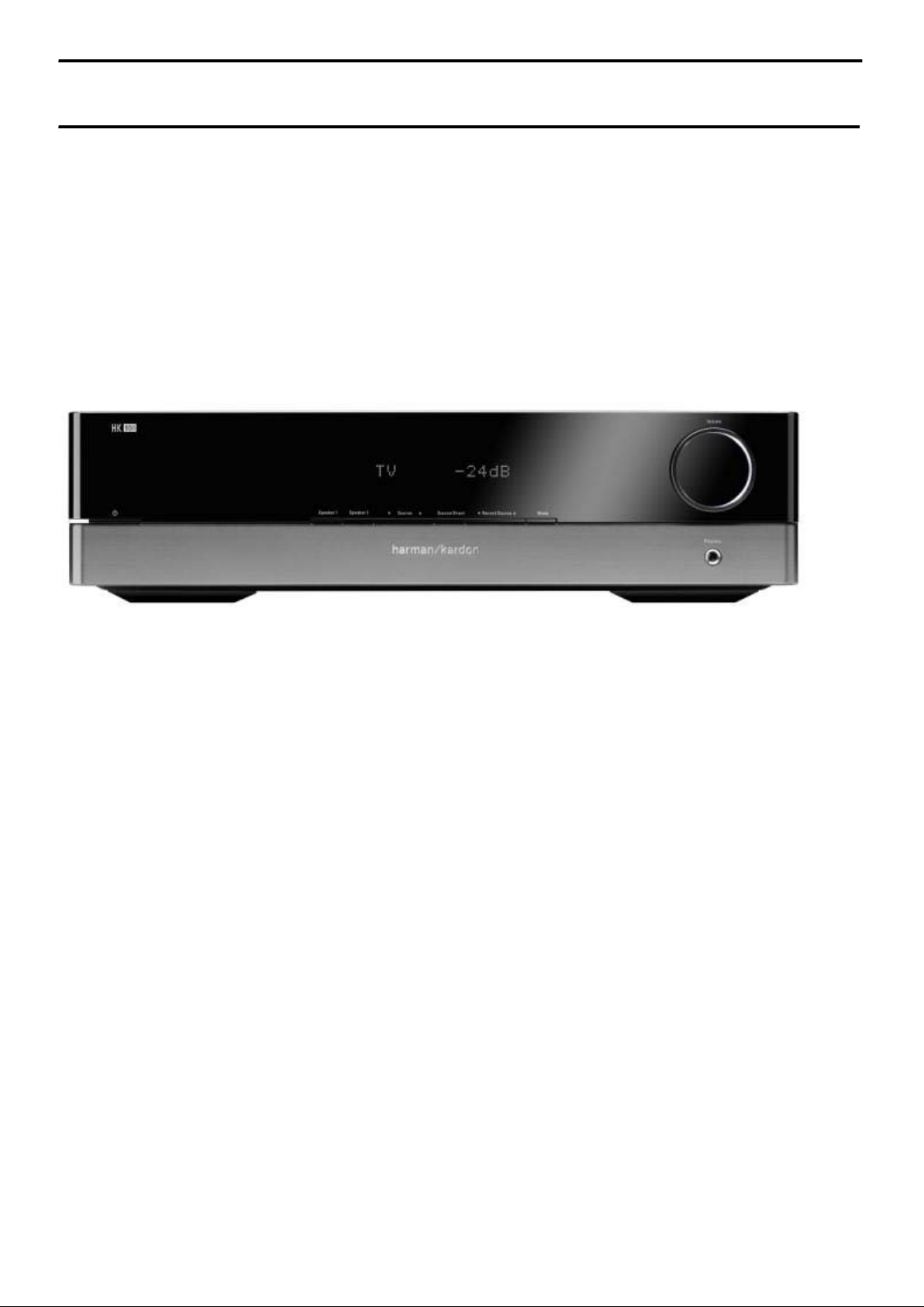
HK 980/230
2 x 80W STEREO AMPLIFIER with REMOTE CONTROL
REAR PANEL CONNECTIONS 3
FRONT PANEL CONTROLS 4
REMOTE CONTROL INFORMATION 5
AMP BIAS ADJUSTMENT 6
WIRING DIAGRAM 7
Released EU2008 harman/kardon, Inc. Rev 2, 05/2012
250 Crossways Park Dr.
Woodbury, New York, 11797
SEMICONDUCTOR PINOUTS 9
PCB DRAWINGS 24
SCHEMATIC DIAGRAMS 32
EXPLODED VIEW AND PARTS 38
ELECTRICAL PARTS LIST 40
FRONT AND MAIN BOARD MATCHING 51
Page 2

Specifications
harman/kardon
HK 980/230 Service Manual
Page 2 of 50
Continuous Average Power Per Channel (FTC)
20 Hz – 20 kHz, both channels driven
Dynamic Power (IHF, 1KHz Tone Burst) 8 Ohms:
High instantaneous current capability (HCC)
Power Bandwidth @ Half-Rated output, 8Ω
Frequency response @ 1W (+0/-3dB)
Damping factor (20Hz-20k Hz)
Signal-to-noise Ratio (Reference rated power
output, A-WTD)
Input sensitivity/Impedance Tuner/CD
Overload:
Tone control range, Bass @ 100 Hz/Treble @
10 kHz
Power supply:
Power consumption:
Dimensions (Width x Height x Depth):
Weight:
8 Ohms:
4 Ohms:
4 Ohms:
2 Ohms:
1 Ohms:
Tuner/CD
Phono (MM):
Phono (MM):
Tuner/CD
Phono (MM):
NOMINAL
80 Watts@<0.09%THD
120 Watts@<0.3%THD
115 Watts
200 Watts
295 Watts
380 Watts
±80 Amps
<10 Hz - 150 kHz
5 Hz - 150 kHz
>125
95 dB
75 dB
270mV/43k Ohms
4.0mV/47k Ohms
6V
90 mV
±10 dB/±10 dB
AC 230V, 50 Hz
410 W
440 x 117 x 358 mm
10.35 kg
Harman/kardon 250 Crossways Park Drive,Woodbury, New York 11797
www.harmankardon.com
Harman Consumer Group International:
2, Route de Tours, 72500 Château-du-Loir, France
© 2005 Harman Kardon, Incorporated
Part 5100-971500-000
Page 3
Connections
y
y
harman/kardon
HK 980/230 Service Manual
Page 3 of 50
Speaker System 1
Right channel
Record Player
Cassette Tape D eck
Input Output
L
Left
right
R
CD Recorder
stem 1
Speaker S
L
Left
right
R
Input Output
L
Left
right
R
L
Left
right
R
Left channel
R
L
RIGHT SPEAKER
RIGHT SPEAKER
Output
1
1
2
2
Right channel
Speaker System 2
CAUTION:
SPEAKER IMPEDANCE
4 MIN:SYSTEM 1 OR 2
8 MIN:SYSTEM 1 & 2
ATTENTION:
IMPEDANCE DES
HAUT-PARLEURS
4 MIN:SYSTEM 1 OU 2
8 MIN:SYSTEM 1 ET 2
Left
L
right
R
External Power Amp Video Player 1
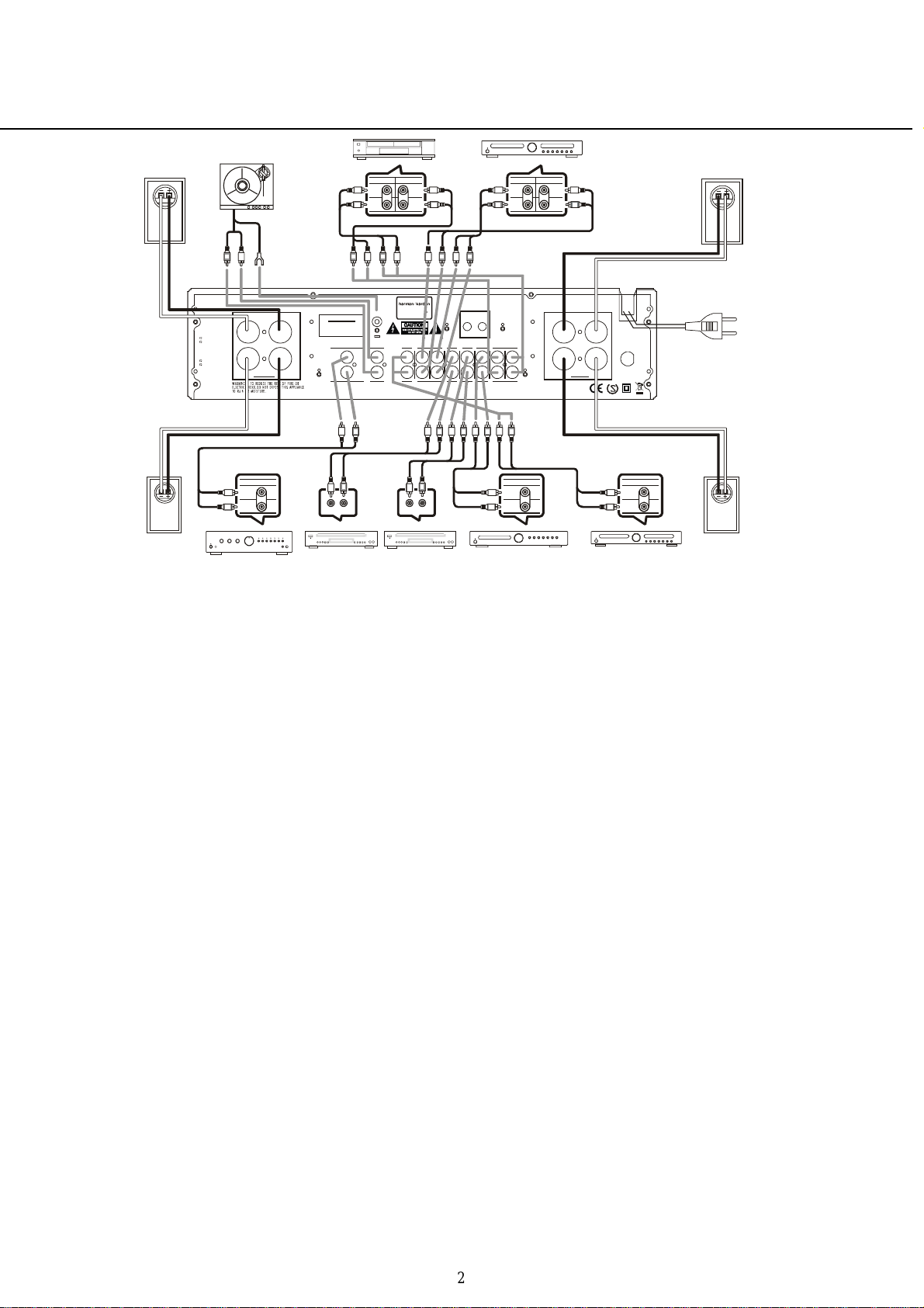
Connecting Other Components
1. Make sure your amplifier and other
components are turned off.
2. Connect each component's
Output/Play jacks to the corresponding
Input jacks on the back of your amplifier
and, if available, the component’s
Input/Record jacks to the Output jacks
of the HK 980. Use the white, black or
gray plugs to connect Left channel jacks;
use the red plugs for Right channel
jacks.
3. A record player with MM cartridge
must be connected to the Phono Input
jacks and a separate ground wire to the
ground terminal screw above.
Wired Remote Control
To control your amplifier with an
external infrared remote sensor,
connect the wire from the remote sensor
to the REMOTE IN jack on the back
panel. Or, if another stereo component
has a built-in infrared remote sensor
and a Remote Output jack, it may be
possible to connect this jack to the
REMOTE IN jack of your amplifier. All
Harman Kardon products with »Remote
In« and »Remote Out« jacks are
compatible with one another, except for
the Citation 22, 24 and 25.
Other manufacturers' remote sensors
and components may not be compatible,
but it will not hurt to experiment. A
second wire may be used to connect
your amplifier's REMOTE OUT jack to
RLR
LRLRL
MODEL NO.:HK 980
NORTHRIDGE
CALIFORNIA , USA
SERIAL NO.
PRE OUTPHONO
LEFT
RIGHT
PRE OUT PHONO
L
R
L
LR
AUDIO OUT
Video Player 2
LEFT
RIGHT
R
GND
MADE IN P.R.C.
SHOCK H AZARD :DO NOT O PEN
AVIS:RISOUE DE C HOC ELECTRIOUE-NE PAS O UV RIR
CD
CD IN CDR OUT AUX TV TUNER
L
LR
AUDIO OUT
R
REMOTE
OUT IN
IN OUT
OUT CDR INAUXTVTUNEROUT TAPE IN
IN TAPE OUT
RLRLRLR
L
L
R
Left
right
Tuner
Output
the Remote Input of another stereo
component. Continue this process to
include additional components (if
compatible).
Connecting Speakers
1. For best performance, use high
quality speaker cables. However,
ordinary copper wire can be used if
the gauge meets the following
requirements:
Wire Min.
Length Diameter
Up to 2.5 meter 1 mm
Up to 4 meter 1.25 mm
Up to 6 meter 1.6 mm
Above 6 meter 2-2.5 mm
2. Avoid rolling excess wire with or near
signal interconnects.
External Power Amplifiers
For applications where higher power is
desired, connect the Pre-Out Jacks to
the Main In Jacks of an external power
amplifier. The level of the output can be
adjusted between -3 and +3 dB with an
internal button. To adjust the level,
gently insert a small screwdriver into the
button and turn clockwise to increase or
counter-clockwise to decrease the
output level.
LEFT SPEAKER
1
1
2
2
LEFT SPEAKER
AC INPUT
AC 230V~50Hz
410W
FUSE
T4AL/250V
E
R
T
E
K
N
I
Output
Left
L
right
R
Compa ct D isc Pla
er
To w all
outlet
Left channel
Speaker System 2
IMPORTANT: When connecting two
pairs of speakers, determine the
impedance of each pair by looking on
the back of the speakers, in your
owner's manual, or by contacting your
dealer or manufacturer.
You can listen to two pairs of
speakers at the same time ONLY if
the impedance of EACH speaker is
NOT LESS THAN 8 Ohms.
WARNING: Do not play sets of
speakers simultaneously except as
recommended above. Amplifier may
overheat.
AC Power
Plug the cord into a 230 VAC wall
socket. Power indicator will light up to
indicate power ON. To completely
disconnect the power input, the main
plug must be disconnected from the
mains.
2
Page 4
Controls and Functions
harman/kardon
HK 980/230 Service Manual
Page 4 of 50
9
980
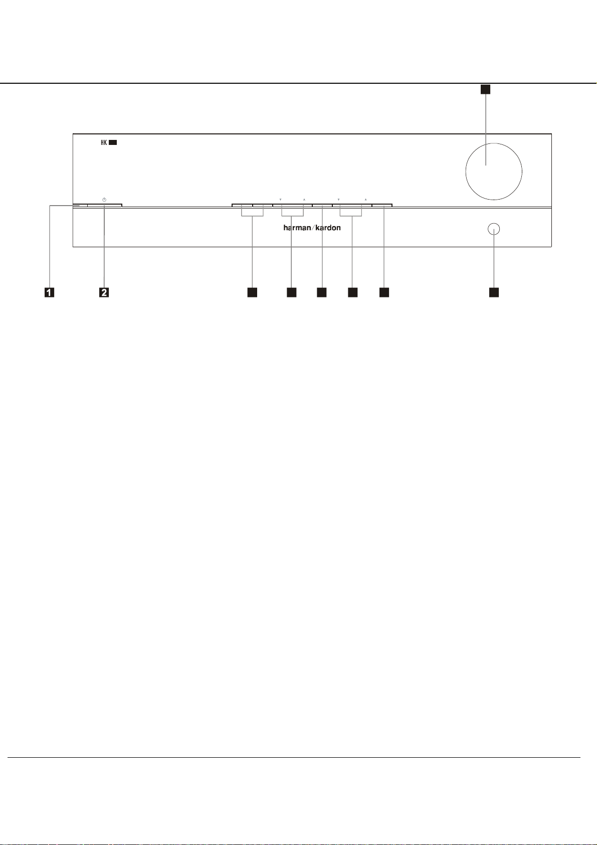
1. Power Indicator: This LED will
illuminate in amber when the unit is in
the Standby mode to signal that the unit
is ready to be turned on.
When the unit is in operation, the
indicator will turn white.
2. System Power Control: Press this
button to turn on the HK 980; press it
again to turn the unit off (to Standby).
Note that the Power Indicator1next to
the switch will turn blue when the unit is
on.
3. Speaker 1 /2 Selectors: Press to
select speaker pair 1 or 2, or both, or
neither (headphone output only).
Speaker 1 Speaker 2
Record Sourc e
Source Direct ModeSource
34567 8
4. Input Source Selector: Select
desired input source for listening by
press-ing the ”Input ource” button
repeatedly (on the left will select
ownwards, right upwards) until the
display for he desired source is
illuminated.
5. Source Direct: Press to bypass tone
control circuitry.
6. Record Source Selector: Select
desired ource for recording to device
connected to the rear panel Tape and
CDR Out sockets by pressing
the ”Record Source” button repeatedly
until the display for the desired source is
illuminated.
7. Mode Button: Press this button to
make changes to the bass, treble and
balance settings.
8. Headphone Jack: Plug in
headphones if desired. With
both ”Speaker 1” and ”2” selectors in the
Off position, output is supplied only to
headphones.
9. Volume Control: Turn to raise or
lower output volume.
Volume
Phones
Page 5
Remote Control
harman/kardon
HK 980/230 Service Manual
Page 5 of 50
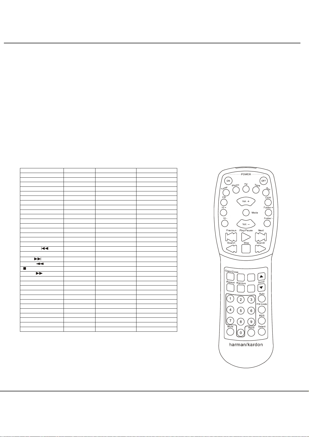
Independent Remote Control
The system remote of the HK 980 can
control the amplifier and compatible
Tuners, CD Players and CD Recorders.
The remote In jack of units without an
integrated IR receiver must be
connected to the amplifier's remote
control output jack so that the system
remote control can operate them.
The Function Table below will show all
functions of the HK 980 and external
devices that can be controlled by the HK
980 remote.
Remote button functions
Button HK 980 CD Player Tuner
ON Power On - OFF Power Off - -
Tuner Select Tuner - Phono Select Phono - TV Select TV - Tape Select Tape - Aux Select Aux - CD Select CD - Volume+ Volume Up - CDR Select CDR - 10+ - Current Track +10 Mode Select Mode - Folder+ - Next Folder 10- - Current Track -10 Volume- Volume Down - Folder- - Previous Folder Previous
►
Play/Pause
Next
Search - Fast Reverse -
Stop
Search
Open/Close - Open/ Close Scroll + - - Tuning Up
Repeat - Repeat Play Random - Random Play Scroll - - - Tuning Down
0 ~ 9 (Numeric Keys) - Track Select Preset Select
Auto - - Auto Tune
FM Mode - - FM Mode Select
RDS - - RDS Mode Select
Mute Mute Sound - Band - - Band Select
Select - - Tune Mode Select
- Skip Previous -
- Play/ Pause -
- Skip Next -
- Stop -
- Fast Forward -
Important Notes:
• To remote control a tuner, CD
Recorder or CD Player, the
appropriate input (”TUNER”, ”CDR”
or ”CD”) must have been selected
with the source buttons of the remote
control (selecting on the front panel is
not sufficient).
• Note that DVD players or tape decks
cannot be controlled by the remote.
• To control a compatible CD
Recorder ”CDR” must be selected as
input and the drive to be controlled
(CDP or CDR) must be selected
appropriately with the ”CDP SELECT”
or ”CDR SELECT” buttons.
Operating Conditions
The control unit operates effectively
within a distance of 7 meters and an
angle of 30° from the amplifier. Using
the control near fluorescent lights may
shorten this range, as will any dust or
dirt that accumulates on the front of the
remote control or the remote sensor
area of the amplifier. Also avoid
blocking the line of sight between
amplifier and remote.
The control unit is powered by two AA
batteries, included with your amplifier.
When you replace weak batteries,
replace both at the same time. When
the remote is to be unused for an
extended period, remove the batteries
to prevent damage from corros
HK 980
Page 6
harman/kardon
HK 980/230 Service Manual
Page 6 of 50
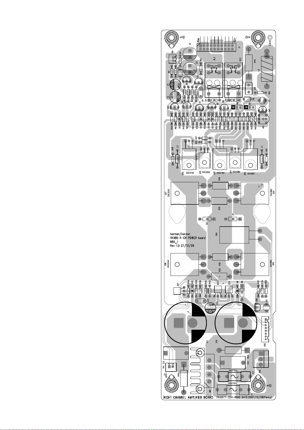
AMP Adjustment
Idling Adjustment
Precaution for handling measuring
instrument.
The ground side of the measuring
instrument to be connected to the
speaker terminal of this unit must be
kept in floating condition, because
this unit is equipped with floating
balanced power amplifier.
Condition
* Start adjustment 20 minutes or
more after the power is turned on.
* Non-loaded condition.
Idling Adjustment
Adjust VR1 so that the DC voltage of
TP1 becomes +10mV to +11mV.
TP1
VR1
NOTE:
Front and main boards must be matched
correctly as below.
FRONT MAIN SW
1.0 (0077-1011-000X) 1.2 1.4
1.1 (0077-1011-0002) 1.2 1.4
1.2 (0077-1011-0003) 1.3 1.5
Serial number cut MAIN 1.3:
FO0001-11844.
Page 7
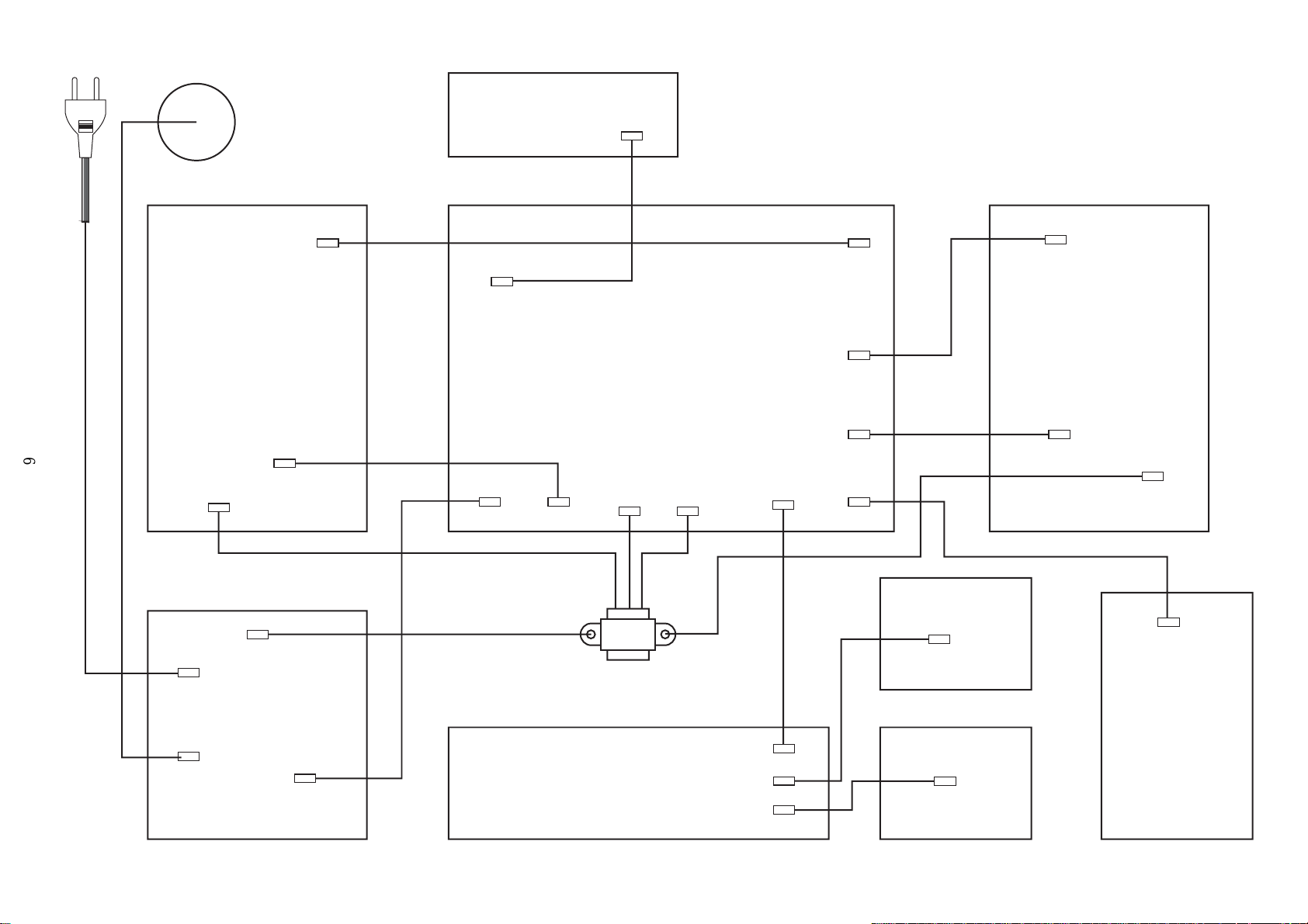
Power Cord in
harman/kardon
HK 980/230 Service Manual
Page 7 of 50
Fuse
IR Board
2P
CN1
3P
CN11
Left Amplifier Board
6
8P
3P
CN3
CN2
3P
CN3
CN1
8P
3P
CN9
Main Board
5P
CN5
6P
CN7
1.00-20P
CN6
2P
CN8
2P
CN9
8P
CN2
4P
CN10
2P
CN1
Right Amplifier Board
8P
CN2
3P
CN3
2P
CN6
2P
CN5
2P
CN7
Power Board
3P
CN8
Transformer
Display Board
1.00-100P
CN1
3P
CN10
2P
CN2
Volume Board
3P
CN11
2P
CN3
Light Board
4P
CN12
Phone Board
Page 8
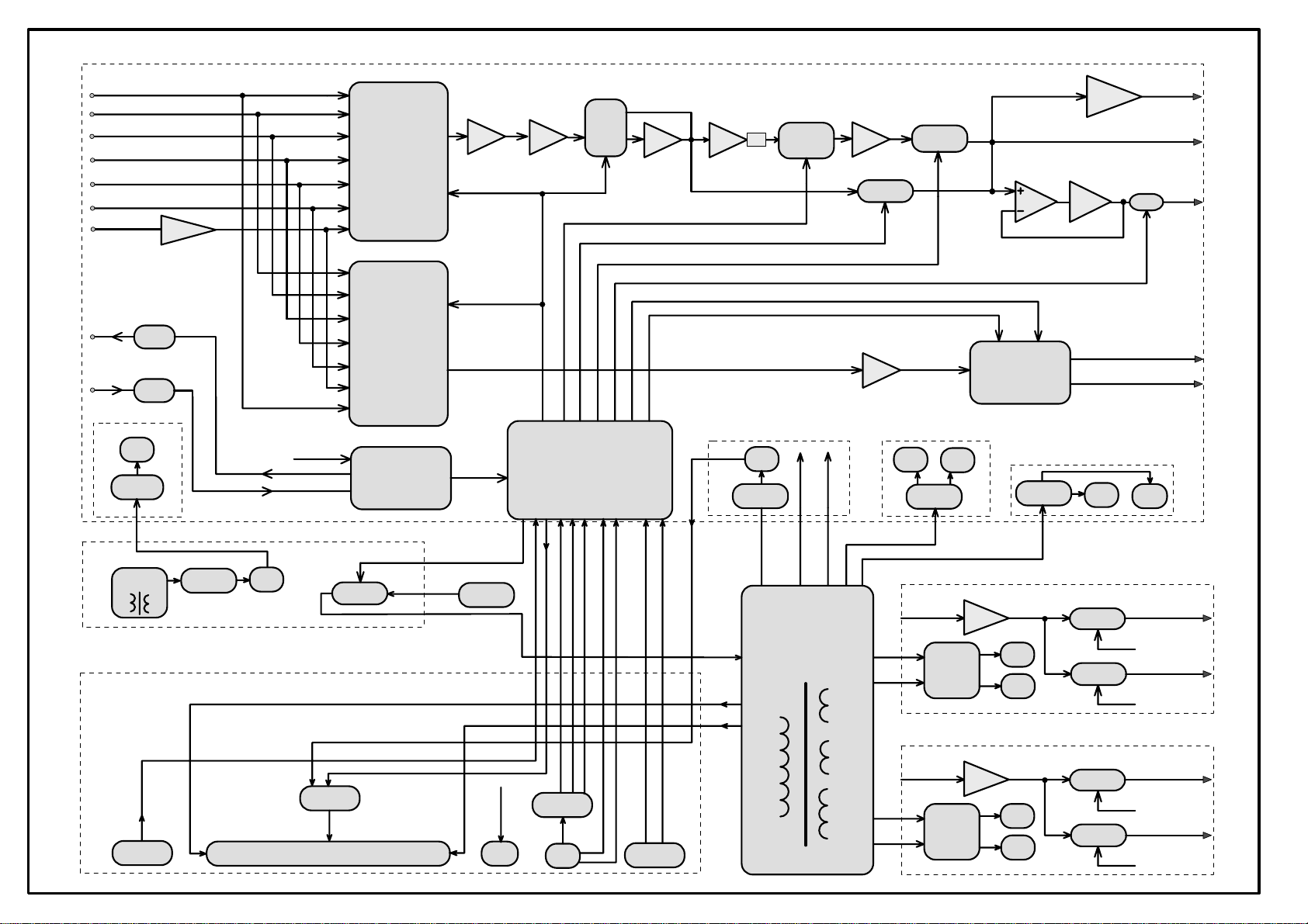
HK980x
harman/kardon
HK 980/230 Service Manual
Page 8 of 50
CD-in
TUNER-in
AUX-in
CDR-in
TAPE-in
TV-in
PHONO-in
mcu+5v
Manostat
IR_OUT
IR_IN
phono amp
mcu+5v
Source
Switch
NJU7311AM
Record
Switch
NJU7311AM
Interface
Buffer
I2C /CS
I2C /CS
Pre Amplifier(1 channel only) & MCU Board
VOL
I2C /CS/MUTE
WM8816
Op amp
Buffer
TONE Control(SPI)
Op amp
MCU
-6dB
-30V
Rectifier
TONE
NJW1119A
F1
+15v
Headphone OUT
AMP X
Pre_ OUT
Relay_3
CDR-OUT
TAPE-OUT
-15v
TPA6120A
+6dB
Relay_2
R2_Ctrl
R1_Ctrl
Buffer
F2
Relay_1
Class A
CDR_CUT
TAPE_CUT
CDR/TAPE OUT CUT
NJU201AM
+5v
Rectifier
+12V
Rectifier
Standby
Transformer
Front Panel Board
IR
Rx
Rectifier
F2
+14v
Fuse Board
Driver
VFD
Relay_8
-30V
Power on/off
F1
Main plug
H/P
H/P OUT
74HC4094
KEY
Master VOL
Main
Transformer
Amp L
Amp L
Rectifier
Rectifier
Left Amplifier Board
Amplifier
+48V
-48V
Right Amplifier Board
Amplifier
+48V
-48V
Relay_4
Relay_5
Relay_6
Relay_7
Speaker L1
R2_Ctrl
Speaker L2
R2_Ctrl
Speaker L1
R2_Ctrl
Speaker L2
R2_Ctrl
Page 9
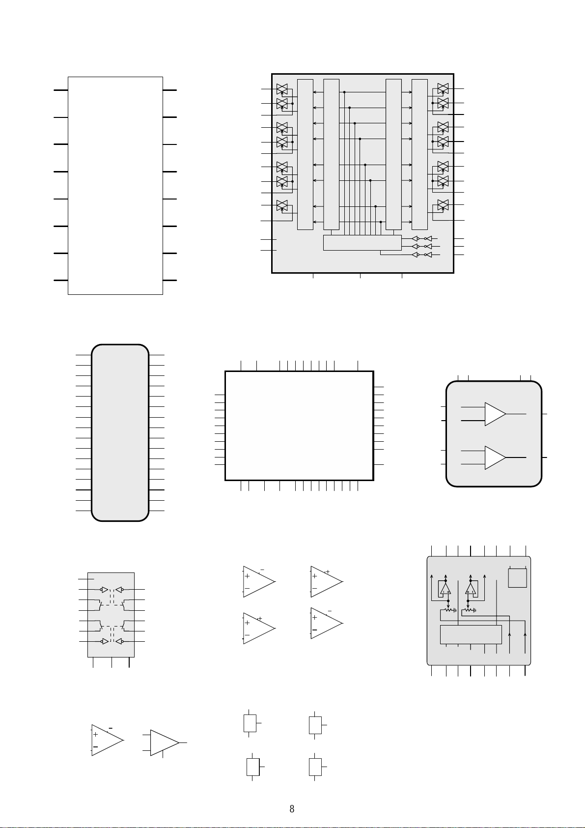
15
harman/kardon
HK 980/230 Service Manual
Page 9 of 50
16
10
IC1
P4.1
IC3
NJU7 31 1AM
2
3
4
5
6
7
8
9
10
11
12
13
18
I
1
C
SM5964C40J(PLCC44)
35
EA#
Lev el Shifter
NC
NC
VDD
30
P0.736P0.637P0.538P0.439P0.340P0.241P0.142P0.0
Latch Circuit
Control Circuit
43
15
44
VCC
P4.2
P1.0
P1.1
P1.2
P1.3
P1.4
P1.5
P1.6
P1.7
RESET
P3.011P4.312P3.113P3.214P3.315P3.416P3.517P3.618P3.719XTA L120XTA L221GND22P4.0
29
28
27
26
25
24
Level Shifter
Latch Circuit
VSS
VEE
1
1
2
3
4
5
6
7
8
9
10
23
22
21
20
19
DATA
CLK
ST
4
IN+
5
IN-
17
IN+
16
IN-
IC6
TPA6120A2DWP
17
16
14
1
20
-VCC
-VCC
+
-
+
-
+VCC3+VCC
LOUT
ROUT
18
2
19
TC4094
3
CL K
2
D
1
ST R
OE
VDD
8
VSS
9
QS
CS
IC
7
NJW1119AV
32
inB
31
GND
30
SWCB
29
outB
28
GND
27
Tone_Tr1b
26
Tone_Mi 1b
25
Tone_Mi 2b
24
Tone_Ba1b
23
Tone_Ba2b
22
N.C.
21
N.C.
20
V+
19
V-
18
ADR1
17
ADR0
Q5
Q6
Q7
Q1
Q2
Q3
Q4
Q8
inA
GND
SWCA
outA
GND
Tone_Tr1a
Tone_Mi 1a
Tone_Mi 2a
Tone_Ba1a
Tone_Ba2a
N.C.
GND
VDDo ut
DATA
CLOCK
LATCH
14
13
12
4
5
6
7
11
1
2
3
4
5
6
7
8
9
10
11
12
13
14
15
16
33
32
31
30
29
28
27
26
25
24
34
ALE/PROG#
PSEN#
P2.7
P2.6
P2.5
P2.4
P2.3
P2.2
P2.1
P2.0
23
IC5
12
10
11
14
15
16
NJU2 01 AM
IC12A
NC
-V4GND
3
OP275GS
2
IC8
NJW1159M
4
3
1
2
IC17A
3
4
1
89
7
6
3
2
1
+V
5
13
IC13B
6
5
-
+
OP275GS
7
V+
8
4
1
NJM5532M
2
IC17B
5
6
NJM5532M
1
I
G
O
3
8
7
IC22
KA780 5
2
1
IC19
KA781 2
I
2
G
O
3
5
NJM2068M
6
3
NJM2068M
2
IC9A
1
I
G
O
3
3
O
G
I
2
8
IC9B
4
IC20
KA781 5
2
IC21
KA791 5
1
7
1
OUT L
BOUTL
BOUTR
VDD_ OUT
&
Logic
Interface
GND
LATCH
CLOCK14DAT A13CE1
16
15
7
5
OUT R
12
8
6
V-
V+
Bias
VSS_OUT
INL
CE0
INR
9
11
10
8
Page 10
harman/kardon
HK 980/230 Service Manual
Page 10 of 50
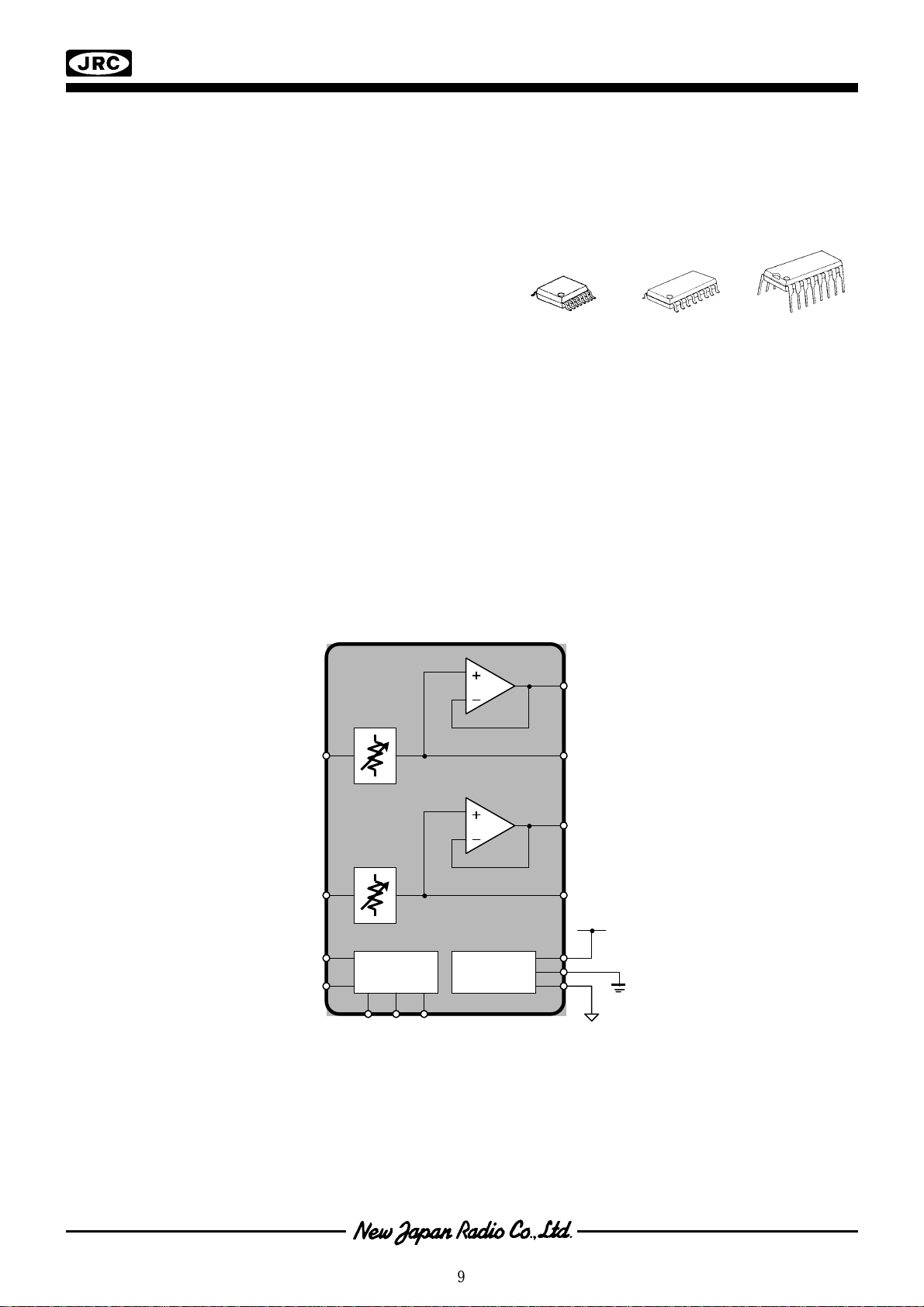
NJW1159
2-CHANNEL ELECTRONIC VOLUME
■■■■ GENERAL DESCRIPTION ■■■■ PACKAGE OUTLINE
NJW1159 is a two channel electronic volume IC. It
is included output buffer amplifier and also resistor
output terminal for using external amplifier to
customize for your application. These functions are
controlled by three-wired serial data. And the chip
selector is available for using four chips on same
serial bus line. It’s available for two-channel stereo
NJW1159V
and or multi-channel audio volume.
■■■■ FEATURES
● Operating Voltage ±4.5 to ±7.5V
● Three-Wired Serial Data Control
● Chip Selector available for using four chips on same serial bus line.
● Volume 0 to -95dB/1dBstep, MUTE
● Bi-CMOS Technology
● Package Outline SSOP16, DMP16, DIP16
NJW1159M
NJW1159D
■■■■ BLOCK DIAGRAM
IN L
IN R
CE0
CE1
3 Wired
Control Data
VOL 1
VOL 2
Inter-face
& Logic
B OUT L
OUT L
B OUT R
OUT R
V+
GND
Bias
V-
9
Page 11

Dual Bipolar/JFET, Audio
OP275
OUT A
–IN A
+IN A
V–
OUT B
–IN B
+IN B
V+
1
2
3
4
5
6
7
8
1
2
3
4
8
7
6
5
OP275
OUT B
–IN B
+IN B
V+OUT A
–IN A
+IN A
V–
harman/kardon
HK 980/230 Service Manual
Page 11 of 50
a
FEATURES
Excellent Sonic Characteristics
Low Noise: 6 nV/√Hz
Low Distortion: 0.0006%
High Slew Rate: 22 V/s
Wide Bandwidth: 9 MHz
Low Supply Current: 5 mA
Low Offset Voltage: 1 mV
Low Offset Current: 2 nA
Unity Gain Stable
SOIC-8 Package
APPLICATIONS
High Performance Audio
Active Filters
Fast Amplifiers
Integrators
GENERAL DESCRIPTION
The OP275 is the first amplifier to feature the Butler Amplifier
front-end. This new front-end design combines both bipolar
and JFET transistors to attain amplifiers with the accuracy and
low noise performance of bipolar transistors, and the speed and
sound quality of JFETs. Total Harmonic Distortion plus Noise
equals that of previous audio amplifiers, but at much lower supply currents.
A very low l/f corner of below 6 Hz maintains a flat noise density
response. Whether noise is measured at either 30 Hz or 1 kHz,
it is only 6 nV/√
the OP275 its high slew rates to keep distortion low, even when
large output swings are required, and the 22 V/µs slew rate of
the OP275 is the fastest of any standard audio amplifier. Best of
all, this low noise and high speed are accomplished using less
than 5 mA of supply current, lower than any standard audio
amplifier.
Hz. The JFET portion of the input stage gives
Operational Amplifier
OP275*
PIN CONNECTIONS
8-Lead Narrow-Body SO 8-Lead Epoxy DIP
(S Suffix) (P Suffix)
Improved dc performance is also provided with bias and offset
currents greatly reduced over purely bipolar designs. Input offset voltage is guaranteed at 1 mV and is typically less than
200 µV. This allows the OP275 to be used in many dc coupled
or summing applications without the need for special selections
or the added noise of additional offset adjustment circuitry.
The output is capable of driving 600 Ω loads to 10 V rms while
maintaining low distortion. THD + Noise at 3 V rms is a low
0.0006%.
The OP275 is specified over the extended industrial (–40°C to
+85°C) temperature range. OP275s are available in both plastic
DIP and SOIC-8 packages. SOIC-8 packages are available in
2500 piece reels. Many audio amplifiers are not offered in
SOIC-8 surface mount packages for a variety of reasons; however, the OP275 was designed so that it would offer full performance in surface mount packaging.
*Protected by U.S. Patent No. 5,101,126.
REV. A
Information furnished by Analog Devices is believed to be accurate and
reliable. However, no responsibility is assumed by Analog Devices for its
use, nor for any infringements of patents or other rights of third parties
which may result from its use. No license is granted by implication or
otherwise under any patent or patent rights of Analog Devices.
© Analog Devices, Inc., 1995
One Technology Way, P.O. Box 9106, Norwood. MA 02062-9106, U.S.A.
Tel: 617/329-4700 Fax: 617/326-8703
10
Page 12
A
harman/kardon
HK 980/230 Service Manual
Page 12 of 50
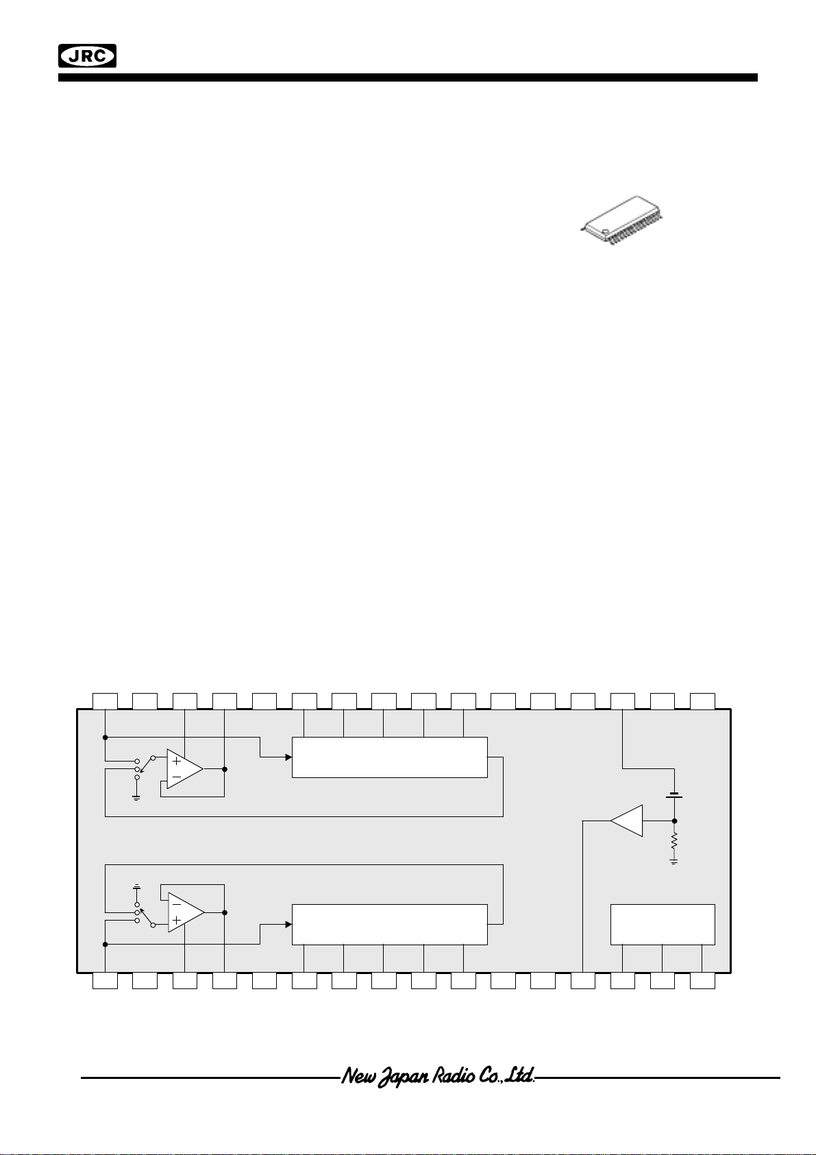
NJW1119
3-Band Tone Control IC
GENERAL DESCRIPTION !!!! PACKAGE OUTLINE
!!!!
The NJW1119A is a Tone Control IC including 3-Band
stereo EQ circuit.
It performs superior audio characteristics such as low
distortion and low output noise. All of internal status are
controlled by three-wired serial bus. Selectable 4-Chip
address is available for using four chips on same serial bus
line.
It is suitable for any audio applications.
APPLICATIONS
!!!!
•AV amplifier/receiver
•Car Audio
•Mini/Micro components
NJW1119AV
FEATURES
!!!!
• Operating Voltage ±4.5 to ±7.5V
• 3-Wired Serial Control Chip Address Select Function
• Low Total Harmonic Distortion 0.0002% typ. @Tone=OFF
• Low Output Noise -120dB typ. @Tone=OFF
• Tone Control 0 to ±12dB/1dB Step (100Hz/1kHz/10kHz)
Bi-CMOS Technology
•
•
Package Outline
SSOP32
• Mute Function
■■■■ BLOCK DIAGRAM
26 25 2432 31 30 29 28 27 19 18 1723 22 21 20
GND
3Band TONE
ADR 1 AD R 0GND
Ref 5V
VDD
Ver 0.0
GND
GND
3Band TONE
GND
7 8 9 1 2 3 4 5 6 14 15 1610 11 12 13
Control Logic
Page 13

harman/kardon
HK 980/230 Service Manual
Page 13 of 50
Page 14
harman/kardon
HK 980/230 Service Manual
Page 14 of 50
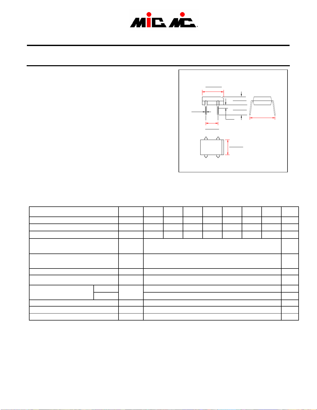
SINGLE-PHASE BRIDGE RECTIFIER
DF005 THRU DF10
DB101 THRU DB107
VOLTAGE RANGE 50 to 1000 Volts
CURRENT 1.0 Ampere
FEATURES
• Glass passivated chip junction
• High forward surge current capability
• Ideal for printed circuit board
• High temperature soldering guaranteed:
260℃/10 seconds at terminals
MECHANICAL DATA
• Case: Transfer molded plastic
• Epoxy: UL94V-0 rate flame retardant
• Terminals solderable per MIL-STD-202E
method 208C
• Polarity: Molded on body
• Mounting position: Any
• Weight: 0.04 ounce, 1.0 gram
MAXIMUM RATINGS AND ELECTRICAL CHARACTERISTICS
• Ratings at 25℃ ambient temperature unless otherwise specified
• Single Phase, half wave, 60Hz, resistive or inductive load
• For capacitive load derate current by 20%
Maximum Reverse Peak Repetitive Voltage
Maximum RMS Voltage
Maximum DC Blocking Voltage
Maximum Average Forward Rectified Output
Current, 0.06”(1.5mm) lead length at TA=40℃
(Note 2)
Peak Forward Surge Current
8.3ms single half sine wave superimposed on
rated load (JEDEC Method)
Rating for Fusing (t<8.3ms)
Maximum Instantaneous Forward Voltage drop
Per Bridge element 1.0A
Maximum Reverse Current at rated
DC blocking voltage per element
Typical Junction Capacitance (Note 1)
Typical Thermal Resistance (Note 2)
Operating and Storage Temperature Range
TA=25℃
TA=125℃
SYMBOLS
V
RRM
V
RMS
VDC 50 100 200 400 600 800 1000 Volts
I
(AV)
I
FSM
I2t 10 A
VF 1.1 Volts
IR
CJ 25
R
ΘJA
TJ ,T
DF005
DB101
50 100 200 400 600 800 1000 Volts
35 70 140 280 420 560 700 Volts
1.0 Amps
50 Amps
40
STG
Notes: 1. Measured at 1.0MHz and applied reverse voltage of 4.0 Volts.
2.Unit mounted on P.C.B. with 0.51”×0.51” ( 13×13mm) copper pads.
DF01
DB102
DFM
.020
(0.5)
DF02
DB103
.365 (9.3)
.320 (8.12)
.205 (5.2)
.195 (5.0)
-
~
Dimensions in inches and (millimeters)
DF04
DB104
0.5
-55 to +150
.135 (3.4)
.115 (2.9)
.165 (4.2)
.155 (3.9)
.060
(1.5)
+
.255 (6.5)
.245 (6.2)
~
DF06
DB105
5
DF08
DB106
.350 (8.9)
.300 (7.6)
DF10
DB107
UNIT
2
s
µAmps
mAmps
pF
℃/W
℃
Page 15
harman/kardon
HK 980/230 Service Manual
Page 15 of 50
&'6;;
&'6.46;
'
*&3,3
))#3 ?-?-
7:,13,-!$$@-3A?&!$3B!
(-!$$@!$$@-3
.#/*0=/)0=/(044#*
'
)*7
Page 16
Filter and
I/V Gain Stage
TPA6120A2
harman/kardon
HK 980/230 Service Manual
Page 16 of 50
www.ti.com
HIGH FIDELITY HEADPHONE AMPLIFIER
FEATURES DESCRIPTION
• 80 mW into 600 Ω From a ±12-V Supply at
0.00014% THD + N
• Current-Feedback Architecture
• Greater than 120 dB of Dynamic Range
• SNR of 120 dB
• Output Voltage Noise of 5 µVrms at
Gain = 2 V/V
• Power Supply Range: ±5Vto±15 V
• 1300 V/µs Slew Rate
• Differential Inputs
• Independent Power Supplies for Low
Crosstalk
• Short Circuit and Thermal Protection
APPLICATIONS
• Professional Audio Equipment
• Mixing Boards
• Headphone Distribution Amplifiers
• Headphone Drivers
• Microphone Preamplifiers
The TPA6120A2 is a high fidelity audio amplifier built
on a current-feedback architecture. This high
bandwidth, extremely low noise device is ideal for
high performance equipment. The better than 120 dB
of dynamic range exceeds the capabilities of the
human ear, ensuring that nothing audible is lost due
to the amplifier. The solid design and performance of
the TPA6120A2 ensures that music, not the amplifier,
is heard.
Three key features make current-feedback amplifiers
outstanding for audio. The first feature is the high
slew rate that prevents odd order distortion
anomalies. The second feature is current-on-demand
at the output that enables the amplifier to respond
quickly and linearly when necessary without risk of
output distortion. When large amounts of output
power are suddenly needed, the amplifier can respond extremely quickly without raising the noise
floor of the system and degrading the signal-to-noise
ratio. The third feature is the gain-independent frequency response that allows the full bandwidth of the
amplifier to be used over a wide range of gain
settings. The excess loop gain does not deteriorate at
a rate of 20 dB/decade.
SLOS431–MARCH 2004
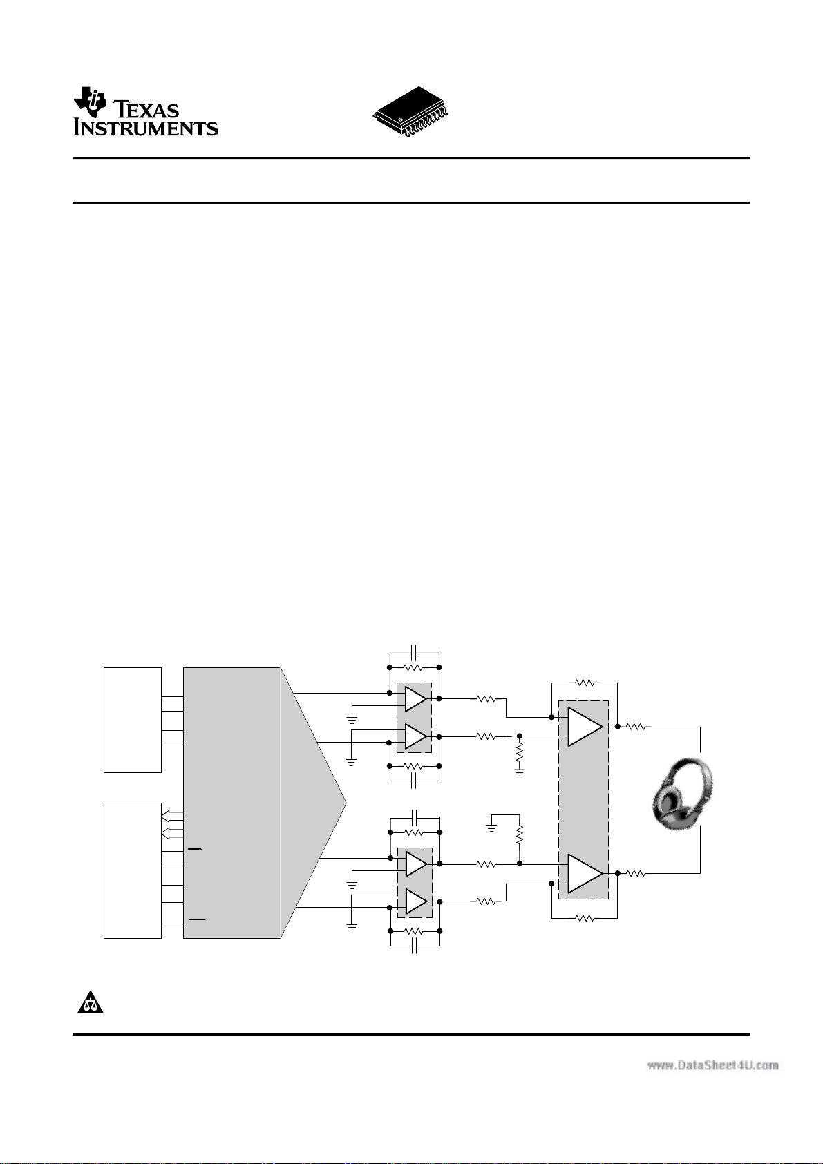
Stereo Hi−Fi
Headphone Driver
TPA6120A2
1 kΩ
LIN−
LIN+
R
F
1 kΩ
R
F
1 kΩ
RIN+
RIN−
1 kΩ
R
F
R
F
PCM
Audio
Data
Source
Controller
LRCK
BCK
DATA
SCK
ZEROL
ZEROR
MS
MDI
MC
MDO
RST
AUDIO DAC
PCM1792
DSD1792
I
L−
OUT
or
I
R−
I
OUT
L+
I
OUT
R+
OUT
−IN A
+IN A
+IN B
−IN B
+IN C
−IN C
+IN D
−IN D
1/2 OPA4134
2.7 nF
C
F
1 kΩ
R
F
1 kΩ
R
F
C
2.7 nF
F
1/2 OPA4134
2.7 nF
C
F
1 kΩ
R
F
1 kΩ
R
F
C
2.7 nF
F
OUT A
OUT B
OUT C
OUT D
R
1 kΩ
R
1 kΩ
R
1 kΩ
R
1 kΩ
I
I
I
I
Please be aware that an important notice concerning availability, standard warranty, and use in critical applications of Texas
Instruments semiconductor products and disclaimers thereto appears at the end of this data sheet.
PowerPAD is a trademark of Texas Instruments.
R
10 Ω
R
10 Ω
O
O
LOUT
ROUT
DYR > 120 dB
for Whole
System!
Page 17

harman/kardon
HK 980/230 Service Manual
Page 17 of 50
16
Page 18

harman/kardon
HK 980/230 Service Manual
Page 18 of 50
Page 19

harman/kardon
HK 980/230 Service Manual
Page 19 of 50
Page 20

harman/kardon
HK 980/230 Service Manual
Page 20 of 50
Page 21

harman/kardon
HK 980/230 Service Manual
Page 21 of 50
Page 22

2SA1162,2SC3326,2SC3361
harman/kardon
HK 980/230 Service Manual
Page 22 of 50
2SA950 , 2SC2120 2SA1035TR, 2SC2406TR
2SC2458,2SA1048
Page 23

2SC5242
harman/kardon
HK 980/230 Service Manual
Page 23 of 50
2SA1962
1. BASE
2. COLLECTOR
3. EMITTER
2SC4793
2SA1837
1. BASE
2. COLLECTOR
3. EMITTER
2SC3502
2SA1380
1. EMITTER
2. COLLECTOR
3. BASE
BF422
MPSA56
2. COLLECTOR
3
BASE
1. EMITTER
2SC1740S 2SC2240
BF423
3
BASE
COLLECTOR
2
1
EMITTER
MPSA06
RS803
2
BASE
COLLECTOR
3
1
EMITTER
1. EMITTER
2. BASE
3. COLLECTOR
1. EMITTER
2. COLLECTOR
3. BASE
1. BASE
2. COLLECTOR
3. EMITTER
-
AC
AC
+
Page 24

harman/kardon
HK 980/230 Service Manual
Page 24 of 50
Page 25

harman/kardon
HK 980/230 Service Manual
Page 25 of 50
Page 26

harman/kardon
HK 980/230 Service Manual
Page 26 of 50
Page 27

harman/kardon
HK 980/230 Service Manual
Page 27 of 50
Page 28

harman/kardon
HK 980/230 Service Manual
Page 28 of 50
Page 29

harman/kardon
HK 980/230 Service Manual
Page 29 of 50
Page 30

harman/kardon
HK 980/230 Service Manual
Page 30 of 50
Page 31

harman/kardon
HK 980/230 Service Manual
Page 31 of 50
Page 32

1
harman/kardon
HK 980/230 Service Manual
Page 32 of 50
2
3
4
5
SPEAKER JOINT BOARD
SPK1
!
D D
D11
1N4148
2 1
RL2
5
436
L1+
12345678910
J2
2X10X2.54mm
0077-1321-000A
C28
104
GND
1
1
SPK2
DY-024(Red)
DY-024(Black)
+48V -48V
!
3
RELAY-CTRL
F1 4A/250V
1
+12V
t
WARNNING
SW1
TEMPERATURE SWITCH(17AM)
D10
1N4148
KT-S-212N
2 1
1112
1314
1516
1718
1920
1112
1314
1516
1718
1920
1
SPK3
DY-024(Black)
C13
224/275V
R44
6K8/2W
C17
12000U/63V
WARNNING
14
23
-+
BR1
RS803
4
!
WARNNING
2
C14
3
1
CN3
5
SPK4
224/275V
R45
C18
4
2
TO *** BRD
CN2
8
SP-CTRL
SP2
SP1
RL3
2X10X2.54mm
!
+48V
R38
3K3 1%
C10
0.1uF/50V
WARNNING
KT-S-212N
436
12345678910
J1
L2+
C29
104
1
DY-024(Red)
6K8/2W
12000U/63V
!
WARNNING
F2 4A/250V
123
!
3P*3.96
FROM TRANSFORMER
C C
WARNNING
Q21
MPSA56
13
2
Q17
1
L2 FB-DIP
3
Q12
2SC3502-E
R24
10 1%
R20
120R 1%
12
Q8
R16
470R 1%
R14
470R 1%
R12
470R 1%
R5
2K 1%
R4
2K 1%
BCE
D8
2SC5242
CBE
2SA1380-E
C4
R40
R39
22K 1%
1N4002
C9
R33
3 2
CBE
BEC
1
1 2
R25
C8
ECB
3
12
Q7
BF423
47U/63V
D12
22K 1%
Q18
3U3/50V
10K 1%
R28100R 1%
Q13
15K 1%
180PF/100V
1N4148
D5
BF422
3
Q16
1
3 2
2SC4793
D4
3
12
1N4002
EBC
2SC5242
1SS81
1 2
R34
15K 1%
R32
R30
3 2
R29
100R 1%
R27
330R 1%
Q5
BF423
3
21
ECB
21
R2
C2
L3 4uH/1R2W
0.22/1W
0.22/1W
R1033K2 1%
Q1
1K 1%
470/25
CN1
R43
C12
5.1R/2W
D7
1N4002
15K 1%
R36
0.22/1W
R35
0.22/1W
1
2
TP1
2P*2.5
12
R23
JUMPER
R21
5K6 1%
C7
D3
BEC
C6
3PF/50V
3
Q2
R7
C2240-GR
R6
C2240-GR
3
R3
33K2 1%
C1
470PF/50V R42
R1
100K 1%
1
2
2P*2.0
B B
RELAY-CTRL
+12V
OVER-LOAD
D6
104MR37
Q23
2SC1740S-R
100R 1%
Q19
2SA1962
32
1
L1 FB-DIP
Q11
NC
3
Q10
1
10U/25V
1SS81
C5
180 1%
180 1%
OVER-ZERO
1 2
CBE
Q15
2SC4793
BEC
470U/25V
1234567
AMP-MUTE
R31
2SA1837
BCE
R22
Q6
8P*2.0
1N4148
2SC1740S-R
Q24
CEB
3
32
1
100R 1%
BEC
32
1
3 2
1.13K 1%
31
CBE
BF422
3
R11
1K07 1%
Q3
MPSA06
2
D1
R8
3
C20
Q20
12
VR1
100R
2
4
Q9
3
1 2
1 3
1N4148
47K 1%
1
-48V
1 2
R46
2K2 1%
2
100/25
2SA1962
CBE
Q14
2SA1380-E
3
3
R18
15K 1%
R26
10 1%
R17
470R 1%
R19
120R 1%
2SC3502-E
1 2
R15
470R 1%
4
D2
R13
1N4148
470R 1%
CEB
2
R41
C3
47U/63V
249R 1%
R9
Q4
MPSA06
1 3
47K 1%
AMP-MUTE
A A
5
Page 33

1
harman/kardon
HK 980/230 Service Manual
Page 33 of 50
2
3
4
5
D11
1N4148
78
2 1
J2
2X10X2.54mm
SPEAKER JOINT BOARD
0077-1321-000A
1
SPK1
DY-024(Red)(BX-R06B)
RELAY-CTRL
+12V
!
WARNNING
SW1
D D
5
12345678910
C28
SPK2
TEMPERATURE SWITCH(17AM)
RL2
KT-S-212N
436
12345678910
R1+
104
GND
1
DY-024(Black)(BX-R06B)
+48V -48V
!
WARNNING
23
3
4
F1 4A/250V
1
2
t
TO *** BRD
CN2
8
SP-CTRL
SP2
SP1
D10
1N4148
RL3
78
KT-S-212N
43652 1
1112
1314
1516
1718
1920
J1
R2+
1112
1314
1516
1718
1920
C29
104
1
1
SPK3
SPK4
DY-024(Red)(BX-R06B)
DY-024(Black)(BX-R06B)
C14
224/275V
C13
224/275V
R45
R44
C17
BR1
6K8/2W
6K8/2W
C18
12000U/63V
12000U/63V
14
-+
RS803
3
4
!
WARNNING
F2 4A/250V
1
2
123
CN3
3P*3.96
FROM TRANSFORMER
+48V
R38
2X10X2.54mm
3K3 1%
C10
0.1uF/50V
!
WARNNING
!
WARNNING
!
WARNNING
C C
Q21
MPSA56
13
2
Q17
1
L2 FB-DIP
3
Q12
2SC3502-E
R24
10 1%
R20
120R 1%
12
Q8
R16
470R 1%
R14
470R 1%
R12
470R 1%
R5
2K 1%
R4
2K 1%
BCE
D8
2SC5242
CBE
2SA1380-E
C4
R40
R39
22K 1%
1N4002
C9
R33
3 2
CBE
BEC
1
1 2
R25
C8
ECB
3
12
Q7
BF423
47U/63V
D12
22K 1%
Q18
3U3/50V
10K 1%
R28100R 1%
Q13
15K 1%
180PF/100V
1N4148
D5
BF422
3
Q16
1
3 2
2SC4793
D4
3
12
1N4002
EBC
2SC5242
1SS81
1 2
R34
15K 1%
R32
R30
3 2
R29
100R 1%
R27
330R 1%
Q5
BF423
3
ECB
R2
C2
L3 4uH/1R
0.22/1W
0.22/1W
BEC
R1033K2 1%
3
21
Q2
C2240-GR
Q1
C2240-GR
21
3
1K 1%
470U/25V
1
2
CN1
R36
R35
1
TP1
R43
5.1R/2W
D7
1N4002
0.22/1W
0.22/1W
2
2P*2.5
12
R23
R21
C6
R7
R6
R3
33K2 1%
C1
470PF/50V R42
R1
2P*2.0
C12
15K 1%
32
JUMPER
5K6 1%
C7
D3
3PF/50V
100K 1%
RELAY-CTRL
104MR37
L1 FB-DIP
Q11
3
10U/25V
1SS81
180 1%
180 1%
8P*2.0
1234567
+12V
OVER-ZERO
AMP-MUTE
OVER-LOAD
D6
1N4148
-48V
2SC1740S-R
Q24
1 2
CEB
3
3
Q23
2SC1740S-R
1 2
100R 1%
Q19
2SA1962
1
Q15
NC
Q10
2SC4793
1
BEC
C5
470U/25V
B B
32
CBE
R31
100R 1%
32
2SA1837
BCE
3 2
R22
1K2 1%
Q6
BF422
3
R11
Q3
D1
R8
C20
1
Q20
BEC
1
12
VR1
100R
2
4
13
CBE
Q9
3
1 2
1K07 1%
MPSA06
1 3
2
1N4148
47K 1%
R46
2K2 1%
100/25
2SA1962
CBE
Q14
2SA1380-E
3
R18
15K 1%
R26
10 1%
R17
470R 1%
R19
120R 1%
2SC3502-E
1 2
R15
470R 1%
D2
R13
1N4148
470R 1%
CEB
2
R41
C3
47U/63V
249R 1%
R9
Q4
MPSA06
1 3
47K 1%
AMP-MUTE
A A
1
2
3
4
5
Page 34

SW6
harman/kardon
HK 980/230 Service Manual
Page 34 of 50
H5mm
SW7
H5mm
SW8
H5mm
SW9
H5mm
SW2
H5mm
SW3
H5mm
SW4
H5mm
SW5
H5mm
14
13
4
Q5
Q6
Q712Q1
IC1
TC4094
D
CLK
3
OE
STR
2
1
16
15
11
Q25Q36Q47Q8
VDD
VSS
QS
8
9
10
CS
C6
104
CN10
3P(2 .0)
GND
3
VOL-B
2
VOL-A
TO VOL BOARD
POW
GND
CN2
TO LED BOARD
GND
GND
GND
+30V
F2
F1
MCU+5V
POWER +12V
STANDBY
VOL-B
IR
VOL-A
KEY2
KEY1
4094-CLK
4094-DA
VFD_RES
VFD_ST
VFD_CLK
VFD_DA
VOL-B
1
VOL-A
1
2
2P(2 .0)
20
19
18
17
16
15
14
13
12
11
10
9
8
7
6
5
4
3
2
1
R23
10R1/8W
F2
F1
MCU+5V
POW
STANDBY
VOL-B
IR
VOL-A
KEY2
KEY1
4094 -CLK
4094 -DA
VFD_RES
VFD_ ST
VFD_CLK
VFD_DA
C2
100U1 0V
L1
10UH
C8
100U1 0V
Q6
2SC24 58
DW1
2SC21 20
Q5
R22
L2
10UH
6A2
1K1/ 8W
C15
47U16 V
R25
10R1/8W
DEL
DEL
R26
22K1/ 8W
C14
104
C33
10u/ 50V
104
C32
C3
100U1 0V
104
C7
TO MC U BOAR
CN1
R16
47
C5
D100-DRA-20
IR1
KSM-803LM
104
C1
100U10V
+V
3
GND
2
OUT
1
820
R24
++
_
GR
LED1
SW1
H5mm
LED Wh ite&Yellow
C27
104
E
R21
120
VFD1
12- BD- 01 INK
F2
F2
NP
NP
NX(12G)
NX(12G)
LGND
NX(11G)
PGND
NX(11G)
VH
NX(10G)
NX(10G)
VDD
NX(9G)
/RST
NX(9G)
OSC
NX(8G)
NX(8G)
/CS
NX(7G)
NX(7G)
CP
NX(6G)
DA
NX(6G)
TSA
NX(5G)
NX(5G)
TSB
NX(4G)
NX
NX(4G)
NX
NX(3G)
NX(3G)
NX
NX(2G)
NX
NX(2G)
NX
NX(1G)
NX(1G)
NP
NP
F1
F1
48
47
46
45
44
43
42
41
40
39
38
37
36
35
34
33
32
31
30
29
28
27
26
25
24
23
22
21
20
19
18
17
16
15
14
13
12
11
10
9
8
7
6
5
4
3
2
1
R1
24K
C31
C13
100P
C12
150P
150P
C11
104
KL-YL-03
33
Page 35

123
harman/kardon
HK 980/230 Service Manual
Page 35 of 50
CN9
LED
GND
1
2
CN3
2P(2 .0)
TO DISPLAY BOARD
LED BOARD
R12
22k
Q4
R18
A104 8
C26
47U1 0V
22k
R15
3K9
3P(2 .0)
TO MCU BOARD
DGND1
REM
MCU+5V1
10uH
L5
L4
10uH
L6
10uH
IR IN/OUT BOARD
R7
R30
150R1/8W
LED5
150R1/8W
LED4
150R 1/8W
LED2
150R1 /8W
LED3
3P(2 .0)
CN11
VOL-A
VOL-B
123
R29
R28
R27
GND
TO DISPLAY BOARD
3
2
R122ECA-D1-19.5F-24-W
JK3
CK-6.35-02
245 K37
L
1
1
8 K
C29
C28
RV1
- +
1L0445W31B0CG201
P/N:0077-1021-0000
- +
1L0445W31B0CG201
- +
1L0445W31B0CG201
- +
1L0445W31B0CG201
P/N:0077-1191-0000
333
C20
333
C19
C9
104
104
C30
103
103
VOL BOARD
Ear Phones board
R
123
CN12
4
4P(2 .5)
PH-L
GND
PH-R
P/N:0077-1171-0000
47K
R14
75
C25
680P
C4
R5
47
JK1
1
RAY1
4
JY103M(X1/400V.Y2/300V)
CN5
100U 10V
R6
47
123
CKX3.5-1 2A
D3
IN4148
R3
10k
C22
100U10V
R4
Q1
C2120
D2
IN4 148
2
C18
3
C16
0.1U/ 27 5VA C(X2)
5D-13
R2
AC I2 F
1
2
2P7.92
4K7
R11
TO Transformer
1
2
KI-S-112M
CN7
AC O2
AC O1
C17
0.1U/270VAC(X2)
L3
R9
4.7M2W
3.3M2W
R8
CN6
4
IC3
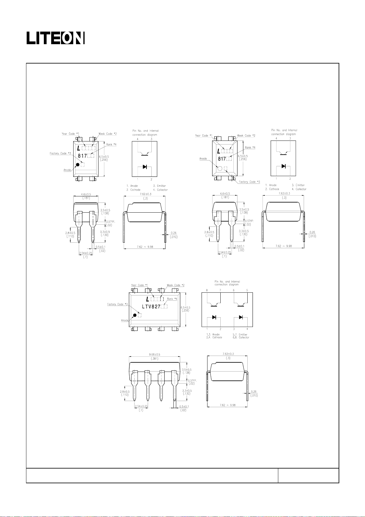
LTV81 7A
1
2 3
C24
NC
C23
123
NC
123
CKX3.5-12A
P/N:0077-1031-0000
3P(2 .0)
R13
270
JK2
CN8
TO MCU BOARD
C10
104
C21
+
470U 25V
AC2
68/0 .25 W
BL1
2P7.92
T1
AC1
-
DB101G
R10
FR 1/ 0.2 5W
6
4
1
3
EI-28
4046-1585-0000(230V)
TC2006-6R8 M-H
AC I2
AC I1
1
2
2P7.92
AC IN
FUSE BOARD
P/N:0077-1101-0000
TO MAIN BRD
KL-YL-03
Page 36

1
harman/kardon
HK 980/230 Service Manual
Page 36 of 50
2
2P7.92
To Fuse Board
SP_CTRL
SP1
SP2
RELAY_CTRL
+12V
OVER_LOAD
OVER_ZERO
AMP_MUTE
8
CN2
TO R-CH AMP
+12V
1234567
8P(2.0)
DGND
SP2
Q36
SS8550D
+12V
R112
47K
R107
470
Q33
2SC3361
R55
10K
SP1
C13
104
DGND
Q37
SS8550D
+12V
R113
47K
R108
470
DGND
C39
22U/10
DGND
R56
RELAY_CTRL
SP_CTRL
SP1
SP2
+12V
OVER_LOAD
OVER_ZERO
AMP_MUTE
8
CN1
C14
104
DGND
Q34
2SC3361
DGND
C43
22U/10
10K
1234567
8P(2.0)
TO L-CH AMP
Q40
FJN3303R
R41
10K
DGND
+5V
R156
1K
R82
10K
DW1
HZK5 B
DGND
OVER HEAT
4
IC23
R109
470
DGND
LTV8 17A
1
2 3
Q39
FJN3303R
DGND
R38
10K
+5V
Q5
2SC3361
DGND
22K
R37
AMP-M UTE
R34
10K
P[1]
DGND
Q4
2SC3361
R154
R155
D6
22K
OVER_LOAD
IN4148
MCU+5V
Q38
2SA1162
GND
+VCC
POWER ON/ OF F
123
CN3
3P(2.0)
TO FUSE BOARD
DGND
C125
470U/25
3P3.96
C112
104
DGND DG ND
1
I
G
2
O
IC22
MCU+5V
DGND
KA7805
3
C124
220U/10
DGND
C111
104
DGND
E
Terminal Erth
C104
104
FB1
22K
IC18
FB08 05
+5V
DGND
123
TO Left Amplifier Board
1
KA78 05
3
123
3P3.96
TO Right Amplifier Board
R206
10R/2W
C122
470U/25V
DGND
1
TO-220
I
G
2
O
DGND
IC19
KA78 12
3
C118
470U/10
DGND
+12V
104
C107
2
1
345
12345
CN5
R208
AC2
+
AC1
C123
2200U/25
C110
104
TO-220
I
G
2
O
C119
220U/16
104
C108
5P(2.5)
R207
RF/0.22/1W
RF/0.22/1W
AC2
BL2
BL1
2W06M
2W06M
-
+
DGND
AC1
C121
1000U/25
DGND
1
104
C109
TO-220
I
G
2
O
DGND
IC20
KA78 15
3
DGND
C117
220U/25
+15V
C105
104
Main
Transformer
1
2
6
345
12345
CN7
R209
RF/0.22/1W
-
C120
1000U/25
C113
104
2
TO-220
I
G
1
O
KA7915
3
IC21
C116
220U/25
C106
104
-15V
6
6P(2.5)
DGND
C126
10U/ 50
DGND
6C2
DW2
R231
RF 1/ 0.25W
D1
1N4001
C128
100U/50
DGND
R230
680/0.25W
DW3
1N4751A(30V)
DGND
C127
47U/ 35
DGND
DEL
10K
10K
10K
10K
10K
10K
10K
10K
R81
R80
R79
R78
R77
R76
R75
R74
R73
DGND
SDA
SCL
WP
VCC
678
IC2
123
4 5
AT24 C02 AN-10S I-2. 7
A0A1A2
DGND
C90
104
C89
DGND
C52
100U/16
DGND
C88
104
C51
100U/16
P4.21P1.02P1.13P1.24P1.35P1.46P1.57P1.68P1.7
VCC
MCU+5V
44
P0.0
43
P0.1
42
P0.2
41
P0.3
40
P0.4
39
P0.5
IC1
38
P0.6
37
P0.7
36
35
34
SM5964C40J(PLCC44)
EA#
P4.1
33
10U/ 16
R72
10
9
P3.0
RESET
P4.3
P3.1
P3.2
P3.3
P3.4
P3.5
P3.6
P3.7
MCU
XTAL1
XTAL2
GND
P4.0
P2.024P2.125P2.226P2.327P2.428P2.529P2.630P2.731PSEN#32ALE/ PROG#
10K
R91
R92 10K
R90 10K
R148 33
R147 33
R146 33
R145 33
R144 33
R143 33
R142 33
R141 33
10K
DGND
RXD
11
12
TXD
13
14
15
16
17
18
19
20
21
22
23
16PF
Z1
C115
12MHz
R218
4.7K
16PF
C114
DGND
MCU+5V
+12V
R140 33
R139 33
R138
33
MCU+5V
DGND
20
19
GND
18
17
-30V
F2
16
F1
15
MCU+5V
14
13
12
11
10
9
8
7
6
5
4
3
2
1
CN6
1.0D-20P
3
2
1
CN11
P ON/VOL-LED
STANDBY-LED
VOL-B
IR
VOL-A
STB- KEY
KEY-IN
4094-CLK
4094-DA
TO DISPLAY BOARD
VFD-RET
VFD-ST
VFD-CLK
VFD-DA
DGND
DGND
REM
MCU+5V
3P(2.0)
TO REM IN/OUT BOARD
Pro OU T MUTE
P[1]
KF-YL-03
10K
10K
R54
R62
R57 10K
AMP-MUT E
TONE -DAT A
TONE -LAT CH
TONE /VOL-C LK
P[1]
P[1]
P[1]
P[2]
10K
2.4K
10K
R71
R149
R58
R61 2.2K
R60 2.2K
R59 10K
R64 10K
R63 10K
33
R13033R131
CDR-CUT
TAPE- CUT
P[1]
P[1]
R70 10K
R69 10K
R68 10K
R67 10K
R66 10K
R65 10K
AN_SW_ STB 2
VOL-C S
DIRECT ON/OF
VOL-M UTE
P[1]
P[1]
P[1]
P[1]
10K
R84
33
R13233R13333R134
AN_SW_ CLK
AN_SW_ STB 1
AN_SW_ DA TA
VOL-D A
P[1]
P[1]
P[1]
P[1]
10K
10K
10K
R13
1.8K
2SC3361
R11
10K
Q3
6
DCD1RXD
Q2
D5
IN4148
R12
10K
D4
IN4148
2SA1162GR
2
DSR
R10
TXD3DTR
RTS7CTS
C10
1U/50
4.7K
8
DGND
123
UPDA
DGND
SW1
SSYB-22D01-G2-0A
Normal
5
4
9
GND
RI
R89 10K
R88 10K
R85
R87
R86
R83 10K
MCU+5V
JK5
Software UPDA
6222-09-M-S0-U-01
Page 37

R
harman/kardon
HK 980/230 Service Manual
Page 37 of 50
C164
+15V
R215
VOL
R53 100
R135 100
VOL-CS
TONE/VOL-C LK
P[2]
P[2]
-15V
KF-YL-03
330P
R52
100
C64
3.3k-1 %
100U/16
C61
100U/16
7
C21
104
8
R175
27K-1%
6
5
OP275GS
IC11B
30P
C11
R173
22U/16
C145
10uF/ 16V
C205
2
4
1
3
OUTL
BOUTL
BOUTR
VDD_OUT
IC8
NJW1159M
&
Logic
Interface
GND
LATCH
CLOCK14DATA13CE1
16
15
C30
100P
C29
100P
104
C12
100
100P
C207 104
C208
R50
VOL-DA
1
P[2]
4
2
3
OP275G S
104
C15
IC11A
C60
OPEN
R4
1K-1%
C55
R212
100
100U/16
C53
R232
330K-1 %
100U/16
SOURCE R-OUT
P[1]
TAPE L-IN -(REC )
TAPE L-OUT
TAPE R-OUT
R166
1K-1%
1K-1%
R163
1K-1%
R94
R93
10K-1%
10K-1%
C133
220P
C129
220P
JK2D
AV-8P
7G48
L
R
TAPE OUT
R
L
L
330P
C163
R51
C65
100U/16
3.3K-1 %
104
C20
7
10P
C157
R211
100K-1 %
10K-1%
22U/16
C206
C66 10uF /16V
5
6V+7
OUTR
VSS_OUT
CE0
11
12
R151
0R
R213
C158 OPEN
R204
OPEN
10P
8
IC12B
R200
27K-1%
6
5
C156
OP275GS
C9
30P
R174
10K-1%
R210
100K-1 %
VOL-7V
VOL-7V
VOL+7V
8
V-
Q22
Bias
INR
9
10
R150
1K-1%
1K-1%
C57
100U/16
C58
2SA950
-15V
INL
VOL+7V
Q21
2SC2120
R43
3.3k-1 %
+15V
R42
3.3k-1%
100U/16
104
C16
1
4
2
3
OP275G S
IC12A
C56
R9
OPEN
1K-1%
C54
R233
100U/16
330K-1 %
SOURCE L-O UT
P[1]
R
-15V
R214
100
C59
100U/16
C17
104
2
3
-
+
V-
4
1
IC13A
OP275GS
10K-1%
R101
104
C19
C23
C63
DW7
R172
1K
C18
104
C162
100U/16
C24
DW6
R171
1K
0R
R205
C146 OPEN
R203
OPEN
R250
100U/16
47U/16
7.5V
47U/16
7.5V
10K-1%
+15V
R223
100
C73
100U/16
C33
104
P[1]P[1]
CD R-IN
AUX R-IN
TV R-IN
CDR R-IN
292827262524232221
SOURCE SELECT
IC4
NJU7311 AM
2345678
AUX L-IN
CD L-IN
TV L-IN
CDR L-IN
CD R-IN-(REC)
AUX R-IN-(REC)
TV R- IN-( REC)
CDR R-IN-(REC)
292827262524232221
REC-OUT SOURCE
IC3
NJU7311 AM
2345678
TV L-IN-(REC)
CDR L-IN-(REC)
AUX L-IN-(REC)
CD L-IN-(REC)
TAPE R-IN
TAPE R-IN-(RE C)
TUNER R-IN-(REC)
TV L-IN-(REC)
TAPE L-IN
1K-1%
R167
1K-1%
1K-1%
R164
R117
R114
R157
47K-1%
R158
47K-1%
C134
220P
C130
220P
JK2C
5G36
L
R
TAPE IN
TV L-IN
TUNER L-IN-(REC)
TUNER L-IN
TUNER R-IN
1K-1%
R169
1K-1%
R168
1K-1%
R165
R118
R116
R115
R161
1K-1%
1K-1%
R159
AV-8P
L
47K-1%
R160 1K-1%
47K-1%
47K-1%
C135
220P
C132
C131
220P
220P
JK2B
AV-8P
3G24
2G11
L
R
TV IN
TUNER IN
PHONO R- IN
TAPE R -IN
TUNER R-IN
SOURCE R-OUT
19
20
Level S hifter
Latch Cir c uit
Latch Cir c uit
Level Shif ter
9
10
11
12
SOURCE L-O UT
TUNER L-IN
PHONO L-IN
TAPE L-IN
TUNER R-IN-(REC)
TAPE R-IN-(RE C)
PHONO R-IN- (REC)
19
20
Level S h ifter
Latch Circuit
Latch Circuit
Level Sh ifter
9
10
11
12
TUNER L-IN-(REC)
TAPE L-IN -(REC )
PHONO L-IN-(REC)
AUX L-IN
AUX L-IN-(REC)
TV R-IN-(REC)
TV R-IN
R170
1K-1%
R162
R119
47K-1%
C136
220P
R
AUX R -IN
1K-1%
1K-1%
R176
R123
R189
1K-1%
R190 1K-1%
R120
47K-1%
47K-1%
C141
220P
C137
220P
JK2A
AV-8P
7G48
L
AUX IN
L
-15V
R217
100
C62
100U/16
C22
104
2
3
-
+
V-
4
1
IC14A
OP275G S
10K-1%
R102
R251
10K-1%
-7V-7V
R247
4.7K-1 %
C100
R249
10U/16
C99
10U/16
2.2n F/50V-J
33nF/ 50V-J
C97 10U/16
1
2
inA
GND
4.7n F/50V-J
C182
C178
C180
4
3
8
5
6
outA
GND
SWCA
Tone_Tr1a
Tone_B a1a9Tone_B a2a
Tone_Mi1a7Tone_Mi2a
TONE
32
C181
C177
IC7
NJW1119AV
C94
10U/16
L
R47
100K-1 %
C152
100P
R99
10K-1%
6
5
10P
-
+
V+
8
R97 10K-1%
C160
7
OP275GS
IC13B
C71
100U/16
R3
3.3K-1 %
P[2]
P[2]
P[2]
AN_SW_CLK
AN_SW_STB2
AN_SW_DATA
C50
100P
16
14
17
ST
CLK
DATA
VEE
1
VSS
15
Control Circuit
VDD
30
NC13NC
18
P[2]
P[2]
P[2]
AN_SW_CLK
AN_SW_STB1
AN_SW_DATA
C151
100P
C150
100P
C149
100P
16
17
14
ST
CLK
DATA
-15V
R241
VEE
1
100U/16
C168
C27 104
VSS
15
Control Cir cuit
104
100U/16
C26
C167
VDD
30
NC13NC
AUX R-IN-(REC)
R177
1K-1%
JK1D
AV-8P
R
R240
+15V
18
CDR L-IN-(REC)
CDR L-OUT
CDR R-OUT
CDR L-IN
R187
R186
1K-1%
1K-1%
1K-1%
R96
R95
R178
10K-1%
R183 1K -1%
10K-1%
C142
220P
C139
C138
220P
JK1C
AV-8P
5G36
L
L
R
CDR OUT
C179
10U/16
4.7nF/ 50V-J
10U/16
33nF/ 50V-J
C95
R248
C96
2.2nF/ 50V-J
R246
4.7K-1%
R
R48
100K-1%
C153
+15V
R224
100
C74
100U/16
C34
104
6
5
-
+
V+
8
7
IC14B
OP275G S
C72
100U/16
-15V
R245
47
47U/16
C172
C32 104
104
47U/16
C31
C171
47
R243
+15V
R-in
R193
100K-1 %
C70
100U/16
C69
100U/16
C28
104
8
5
R222
100
+15V
C68
100U/16
47
47
R124
R121
47K-1%
C143
220P
CDR IN
-15V
CD L-IN
CDR R-IN
CD L-IN-(REC)
CD R-IN
CDR R-IN-(REC)
1K-1%
R184
1K-1%
R182
1K-1%
R179
R122
1K-1%
R125
R188 1K-1%
47K-1%
R180
47K-1%
47K-1%
C144
CD/L
220P
220P
C140
220P
JK1B
AV-8P
2G11
3G24
L
R
R
CD IN
C101
10U/16
3.9K-1 %
C184
10
C183
3.9K-1 %
C93
10U/16
100P
R2
3.3K-1 %
7
NJM2068M
R234
330K
R220
CD R-IN-(REC)
R181
1K-1%
JK1A
AV-8P
-7V
100nF/50V-J
11
12
N.C.
GND
100nF/ 50V-J
-7V
+7V
10P
R98 10K-1%
C161
13
1
2
3
6
7
89
IC9B
6
PHONO L-IN- (REC)
R191
100
C67
100U/16
C25
104
IC17A
C91
R44
R185
L2
P[2]
P[2]
P[2]
TONE-DATA
TONE-LATCH
TONE/VOL-C LK
R272
47
18
+15V-15V
3
104
C46
C2
+15V
R252
1K
DW4
C98
10U/16
14
15
16
13
DATA
LATCH
CLOCK
VDDout
ADR017ADR118V-19V+20N.C.21N.C.22Tone_B a2b23Tone_B a1b24Tone_M i2b25Tone_M i1b26Tone_T r1b27GND28outB29SWCB30GND31inB
R216
1K
C44
104
C86
100U/16
104
C35
C85
100U/16
10K-1%
R100
4
5
-V
+V
GND
16
15
14
11
10
NC
12
C81
100U/16
C40
104
R221
100
-15V
C80
PHONO L-IN
R192
1K-1%
C189
562M
1K-1%
R103
C92
10U/16
10K-1%
R110
470-1%
1
R238
560K-1%
4
47K-1%
2
3
NJM553 2M
C185
R128
C165
102M
R255
C175
680-1%
47U/16
R46
100K-1 %
R49
100K-1 %
C155
100P
C148
100P
C102
10U/16
10U/16
R45
100K-1%
100K-1 %
R194
1K-1%
1K-1%
C154
100P
C147
100P
L3
47UH
47UH
JK3
2G1
L
R
PHONO IN
7.5V
Q41
2SC2120
C174
47U/16
+7V
-15V
R253
1K
DW5
7.5V
Q44
2SA950
C173
47U/16
-7V
DIRECT-R
DIRECT-L
RELAY2
5
JRC-27F/005-M -555
TONE-R
TONE-L
P[2]
P[2]
CDR-CUT
TAPE-CUT
IC5
NJU201AM
L-in
100K-1 %
R197
C82
100U/16
1
4
IC9A
2
3
NJM206 8M
R235
330K
100U/16
CDR R-OUT
TAPE R -OUT
CDR L-OUT
TAPE L-OUT
PHONO R-I N
PHONO R-IN-(R EC)
R196
1K-1%
C190
562M
R195
1K
+15V
C103
10U/16
R104
10K-1%
R225
100
C77
R111
100U/16
470-1%
C37
104
C187
562M
182M
RCA-207C
C188
562M
7
R239
560K-1 %
8
47K-1%
6
5
NJM5532M
C186
R129
IC17B
L
182M
C166
102M
R256
C176
47U/16
680-1%
RELAY1
JRC-27 F/005- M-555
R136
47K-1%
R137
47K-1%
C4
330P
C3
330P
JK4
AV-2P
2G1
R
Pre OUT
100U/16
C1
100U/16
C45
104
20
R271
47
1
R202
330
R-OUT
Q42
C2120
DGND
D3
1N4148
6 124 3
B A
+5V
L-OUT
R201
330
R242
VOL-MUTE
P[2]
+15V
+15V
C204
470P
R126
3.3K-1%
BA561243
+5V
DGND
C169
100U/16
R199
1K
DIRECT ON/OF
P[2]
Q8
2SC3361
22K
DGND
R153
10K
DGND
R152
10K
Q7
R227
22K
2SC3361
R278
2.2K 1%
R198
22K
MCU+5V
R277
Q6
2.2K 1%
2SA1162
5
C42
104
C83
100U/16
R228
100
+15V
Q30
2SA1035 TR
R28
330R 1 %
R36
15K 1%
Q29
2SA1035 TR
Q28
2SA1035 TR
R6
680R 1 %
R27
330R 1%
Q11
2SC2406TR
C41
104
R26
330R 1%
C6
47U/25
R275
2.2K 1%
3
C38
104
C78
100U/16
R226
100
-15V
R24
330R 1 %
R35
15K 1%
Q27
2SA1035 TR
Q26
2SA1035 TR
R23
330R 1%
R5
Q25
680R 1 %
2SA1035 TR
C36
104
Q9
R21
330R 1 %
C5
47U/25
2SC2406TR
C75
100U/16
R273
100R 1 %
Q1
C2120
DGND
D2
DGND
1N4148
C49
R1
1K
100U/16
Pro OU T MUTE
P[2]
GND
123
4
CN10
4P(2.5)
C197
470U/10 V
R254
10R
R
2
+VCC
LOUT
+VCC
+
-VCC
-VCC
IN+
5
4
R18
51
R201KR33
C199
C191
100U/16
R
104
C84
C170
R263
100
100U/16
+15V
104
C79
C87
R262
100
100U/16
-15V
2SC3326
Q17
R229
22K
-15V
R268
100K
C202
330P
6
8
OP275G S
7
IC15B
R
R40
100R 1 %
2SC2406TR
Q12
R8
680R 1 %
Q32
R25
330R 1 %
R
R276
2.2K 1%
C201
330P
2
4
1
IC15A
OP275G S
TO H/P BOARD
C198
470U/10V
R269
470
R270
470
R257
10R
R17
1K
L
R16
1K
19
ROUT
-
-
+
IN-
IN-16IN+
IC6
TPA6120A2DWP
17
R15
1K
R14
1K
R19
51
1K
102
C200
102
R259
22K
C192
100U/16
L
Q20
2SC3326
Q19
2SC3326
R261
1K
R258
22K
7
IC16B
2.2K
10P
8
6
5
NJM553 2M
R267
C196
R266
30P
1.5K
C194
R260
1K
1
2.2K
10P
4
2
3
NJM553 2M
R265
C195
IC16A
C193
30P
R264
1.5K
2SC3326
Q18
R244
22K
DGND
C159
22U/50
R282
2.2K 1%
R281
2.2K 1%
2SC2406 TR
Q16
R32
330R 1 %
Q15
2SC2406TR
R31
330R 1 %
2SA1035 TR
C48
104
C8
47U/25
-15V
R280
2.2K 1%
R279
2.2K 1%
L
R39
100R 1%
L
R30
330R 1 %
Q14
2SC2406TR
Q10
Q13
2SC2406TR
2SC2406TR
R29
330R 1%
R7
680R 1%
Q31
2SA1035 TR
C47
104
R22
330R 1 %
C7
47U/25
-15V
R274
100R 1 %
C76
C203
470P
R127
3.3K-1 %
R105
1
2
CN8
2P(2.0)
L-OUT
TO POWER AMP (L-CH)
100U/16
100K-1 %
R106
100K-1 %
1
2
CN9
2P(2.0)
R-OUT
TO POWER AMP (R-CH)
Page 38

harman/kardon
HK 980/230 Service Manual
Page 38 of 50
Page 39

980 Explode List
harman/kardon
HK 980/230 Service Manual
Page 39 of 50
NO PART.NO QTY
1
2
3
4
5
6
7
8
7648 1010 0000
7448 1020 0000
7548 1010 0000
6048 1010 0000
7448 101C 0000
7448 103A 0000
7048 101D 0000
7348 101A 0000
9 0077 1011 0001 1
10
11
12
5548 103A 0000
7348 102B 0000
7548 103B 0000
13 0077 1171 0001 1
14 0077 1191 0001 1
15 0077 1021 0001 1
16
17
5348 101C 0000
6148 101B 0000
18 0077 1101 0001 1
19 4070 1965 0001 1
20
21
22
6248 101C 0000
7948 1010 0000
5348 102B 0000
23 0077 1291 0000 1
24
25
5148 1010 0000
7948 102B 0000
26 0077 1257 0001 1
27 0077 1321 0000 2
28
7548 1050 0000
29 0077 1031 0001 1
30 0077 1582 0002 1
31
6348 101B 0000
32 5011 3008 0010 20
33
5013 3010 0010
DESCRIPTION
VOLUME KNOB COVER
VOLUME KNOB LENS 1
VOLUME PASTEM
AL PANEL
DISPLAY LENS
STANDY LENS
PASTEM PANEL
POWER KNOB
DISPLAY PCB
EARTHING CUPREM
FUNCTION KNOB
DISPLAY BRACKET
PHONES PCB
VOL PCB
LED PCB
SUBPANEL
TOP COVER
FUSE PCB
TRANSFORMER
BOTTOM COVER
FOOT
PCB BRACKET
RIGHT AMP PCB
HEATSIINK
RS232 COVER
LEFT AMP PCB
SPEAKER CONNECT PCB
SPEAKER BRACKET
IR IN/OUT PCB
MCU & VOL & SOURCE & TONE PCB
BACK COVER
SCREW BTBφ3.0x8
SCREW PAφ3.0x10
10
1
1
1
1
1
1
1
3
1
2
1
1
1
4
2
2
1
2
1
Page 40

HK980x PARTS LIST
harman/kardon
HK 980/230 Service Manual
Page 40 of 50
LEFT CHANNEL POWER AMPLIFIER
PN:0077-1257-0002
Used
Part number Part Type Designator Description
=== ============= ======================= ===============================
1 1360 7080 3000 RS803 BR1
1 3100 4020 0200 2P*2.0 CN1
1 3100 4080 0200 8P*2.0 CN2
1 3100 0702 0050 3P*3.96 CN3
1 2342 0610 5040 470PF/50V C1
1 2341 4104 3000 470UF/25V C5
1 2341 4104 3000 470uF/25V C2
2 2340 0710 3020 47UF/63V C3,C4
1 2115 6309 1100 3PF/50V C6
1 2310 4101 1000 10UF/25V C7
1 2217 2182 0200 180PF/100V C8
1 2339 6101 1000 3.3UF/50V C9
1 2318 6101 1000 0.1uF/50V C10
1 2217 3104 2000 104M(0.1uF/100v) C12
2 2210 3224 0600 224/275V C14,C13
2 2304 0711 0153 12000U/63V C17,C18
1 2311 4102 1000 100/25 C20
6 1311 0041 4802 1N4148 D1,D2,D6,D10,D11,D12
2 1310 8000 0812 1SS81 D4,D3
3 1360 7400 2000 1N4002 D5,D7,D8
2 1610 5141 1200 4A/250V F2,F1
1 3109 1010 4983 2X10X2.54mm Double pins 90 degree J1
2 1867 1138 0000 FB-DIP L1,L2
1 1844 0812 0301 4uH/1R2W L3
2 1132 2400 0182 C2240-GR Q2,Q1
2 1180 0060 0622 MPSA06 Q3,Q4
2 1180 4230 0622 BF423 Q7,Q5
2 1180 4220 0622 BF422 Q6,Q18
2 1111 3800 0430 2SA1380-E Q8,Q14
2 1133 5020 0420 2SC3502-E Q12,Q9
2 1134 7930 0000 2SC4793 Q10,Q13
1 1111 8370 0130 2SA1837 Q15
2 1135 2420 0150 2SC5242 Q17,Q16
2 1111 9620 0130 2SA1962 Q20,Q19
39
Page 41

1 1180 0056 0620 MPSA56 Q21
harman/kardon
HK 980/230 Service Manual
Page 41 of 50
2 1131 7400 0140 2SC1740S-R Q24,Q23
2 4712 1002 1204 KT-S-212N RL3,RL2
1 2402 1411 0111 100K 1% 1/6W R1
1 2402 1411 0211 1K 1% 1/6W R2
2 2402 1413 3211 33K2 1% 1/6W R10,R3
2 2402 1412 0211 2K 1% 1/6W R4,R5
2 2402 1411 8111 180 1% 1/6W R6,R7
2 2402 1414 7311 47K 1% 1/6W R8,R41
1 2402 1412 4911 249R 1% 1/6W R9
1 2402 1411 0711 1K07 1% 1/6W R11
6 2402 1414 7111 470R 1% 1/6W R12,R13,R14,R15,R16,R17
4 2402 1411 5311 15K 1% 1/6W R18,R25,R34,R42
2 2402 1411 2111 120R 1% 1/6W R19,R20
1 2402 1415 6211 5K6 1% 1/6W R21
1 2402 1411 3311 1.13K 1% 1/6W R22
2 2402 1411 0011 10 1% 1/6W R24,R26
1 2402 1413 3111 330R 1% 1/6W R27
4 2402 1411 0411 100R 1% 1/6W R28,R29,R31,R37
4 2396 1412 2211 0.22/1W R30,R32,R35,R36
1 2397 1412 2211 10K 1% 1/6W R33
1 2398 1412 2211 3K3 1% 1/6W R38
2 2399 1412 2211 22K 1% 1/6W R40,R39
1 2400 1412 2211 5.1R/2W R43
2 2401 1412 2211 6K8/2W R45,R44
1 2402 1412 2211 2K2 1% 1/6W R46
1 4301 7001 0000 TEMPERATURE SWITCH(17AM) SW1
1 3100 5020 0200 2P*2.5 TP1
1 2415 1251 0103 100Ω(SEMI-FIXED) VR1
RESISTOR 100 OHM ±30% PA0603-VA1-B101
HK980x PARTS LIST
RIGHT CHANNEL POWER AMPLIFIER
PN:0077-1291-0002
Used
Part number Part Type Designator Description
=== ============= ======================= ===============================
1 1360 7080 3000 RS803 BR1
1 3100 4020 0200 2P*2.0 CN1
40
Page 42

1 3100 4080 0200 8P*2.0 CN2
harman/kardon
HK 980/230 Service Manual
Page 42 of 50
1 3100 0702 0050 3P*3.96 CN3
1 2342 0610 5040 470PF/50V C1
1 2341 4104 3000 470uF/25V C2
2 2341 4104 3000 47UF/63V C3,C4
1 2340 0710 3020 470UF/25V C5
1 2115 6309 1100 3PF/50V C6
1 2310 4101 1000 10UF/25V C7
1 2217 2182 0200 180PF/100V C8
1 2339 6101 1000 3.3UF/50V C9
1 2318 6101 1000 0.1uF/50V C10
1 2217 3104 2000 104M C12
2 2210 3224 0600 224/275V C14,C13
2 2304 0711 0153 12000U/63V C17,C18
1 2311 4102 1000 100/25 C20
6 1311 0041 4802 1N4148 D1,D2,D6,D10,D11,D12
2 1310 8000 0812 1SS81 D4,D3
3 1360 7400 2000 1N4002 D5,D7,D8
2 1610 5141 1200 4A/250V F2,F1
1 3109 1010 4983 2X10X2.54mm Double pins 90 degree J1
2 1867 1138 0000 FB-DIP L1,L2
1 1844 0812 0301 4uH/1R2W L3
2 1132 2400 0182 C2240-GR Q2,Q1
2 1180 0060 0622 MPSA06 Q3,Q4
2 1180 4230 0622 BF423 Q7,Q5
2 1180 4220 0622 BF422 Q6,Q18
2 1111 3800 0430 2SA1380-E Q8,Q14
2 1133 5020 0420 2SC3502-E Q12,Q9
2 1134 7930 0000 2SC4793 Q10,Q13
1 1111 8370 0130 2SA1837 Q15
2 1135 2420 0150 2SC5242 Q17,Q16
2 1111 9620 0130 2SA1962 Q20,Q19
1 1180 0056 0620 MPSA56 Q21
2 1131 7400 0140 2SC1740S-R Q24,Q23
2 4712 1002 1204 KT-S-212N RL3,RL2
1 2402 1411 0111 100K 1% 1/6W R1
1 2402 1411 0211 1K 1% 1/6W R2
2 2402 1412 0211 2K 1% 1/6W R4,R5
2 2402 1413 3211 33K2 1% 1/6W R10,R3
41
Page 43

2 2402 1411 8111 180 1% 1/6W R6,R7
M
M
harman/kardon
HK 980/230 Service Manual
Page 43 of 50
2 2402 1414 7311 47K 1% 1/6W R8,R41
1 2402 1412 4911 249R 1% 1/6W R9
1 2402 1411 0711 1K07 1% 1/6W R11
6 2402 1414 7111 470R 1% 1/6W R12,R13,R14,R15,R16,R17
4 2402 1411 5311 15K 1% 1/6W R18,R25,R34,R42
2 2402 1411 2111 120R 1% 1/6W R19,R20
1 2402 1415 6211 5K6 1% 1/6W R21
1 2402 1411 3311 1.13K 1% 1/6W R22
2 2402 1411 0011 10 1% 1/6W R24,R26
1 2402 1413 3111 330R 1% 1/6W R27
4 2402 1411 0411 100R 1% 1/6W R28,R29,R31,R37
4 2396 1412 2211 0.22/1W R30,R32,R35,R36
1 2397 1412 2211 10K 1% 1/6W R33
1 2398 1412 2211 3K3 1% 1/6W R38
2 2399 1412 2211 22K 1% 1/6W R40,R39
1 2400 1412 2211 5.1R/2W R43
2 2401 1412 2211 6K8/2W R45,R44
1 2402 1412 2211 2K2 1% 1/6W R46
1 4301 7001 0000 TEMPERATURE SWITCH(17AM) SW1
1 3100 5020 0200 2P*2.5 TP1
1 2415 1251 0103 100Ω(SEMI-FIXED) VR1
RESISTOR 100 OHM ±30% PA0603-VA1-B101
HK980x PARTS LIST
DISPLAY-PCB P/N:0077-1011-0001
Used
Part number Part Type Designator Description
=== ============= ======================= ===============================
4 2311 0210 1015 100uF/10V C1 C2 C3 C8
7 2115 6104 0123 0.1uF/50V---0603 C5 C6 C7 C14 C27 C31 C32
2 2115 6151 0123 150P/50V---0603 C11 C12
1 2103 5101 0130 100PF/50V---0603 C13
1 2340 0310 1015 47uF/16V C15
1 2310 0610 1015 10uF/50V C33
1 3104 0120 7002 D100-DRA-20----1.0mm SOCKET CN1
1 3602 4041 5032 2P PLUG TO PLUG 1533#28X1C 2.0 L=150M
1 3303 0504 0115 3P PLUG TO HOUSING2468#26X3C 2.0 L=110
CN2
CN10
1 3833 2001 2620 20P FLEXBILE CABLE TYPE B 1.0 L=260MM
1 1304 0008 0300 KSM-803LM IR1
1 1049 4094 1200 TC4094FN IC1
42
Page 44

2 1841 0012 0000 10uH L1 L2
M
harman/kardon
HK 980/230 Service Manual
Page 44 of 50
1 1402 1203 0015 CS-030C09-OW-C ( LED ) LED1
1 1132 1200 0162 2SC2120 Q5
1 1132 4580 0172 2SC2458 Q6
1 2401 0221 0211 1K--1/8W R22
2 2401 0221 0011 10R1/8W R23 R25
1 2401 0222 2311 22K--1/8W R26
1 2402 1412 4311 24K--1/6W R1
1 2402 1414 7311 47R--1/6W R16
1 2402 1416 8311 68R--1/6W R21
1 2402 1413 3111 330R--1/6W R24
9 4502 4007 8100 TSHC-78A-5.0(WHITE) SW1 SW2 SW3 SW4 SW5 SW6 SW7 SW8 SW9
1 1521 2001 0101 12-BD-01 INK VFD1
HK980x PARTS LIST
FUSE-PCB P/N:0077-1101-0001
Used
Part number Part Type Designator Description
=== ============= ======================= ===============================
1 1361 3011 0100 DB101G BL1
1 2115 6104 0123 104 C10
2 2210 3104 0600 0.1U/270VAC(X2) C17 C16
1 2217 2103 2000 JY103M(X1/400V.Y2/300V) C18
1 2341 0410 1015 470U25V C21
1 2311 0210 1015 100U10V C22
3 3100 0702 1015 2P7.92 CN5 CN6 CN7
1 3303 0504 0225 3P PLUG TO HOUSING2468#26X3C 2.0 L=220
CN8
1 3503 3060 4171 3P PLUG 1672#18X2C UL VH3.96 L=410MM
2 1311 1414 8000 1N4148 D2 D3
1 1132 1200 0162 C2120 Q1
1 1609 2005 1300 5D-13 R2
1 1609 2005 1300 10k R3
1 2401 0224 7211 4K7 R4
1 2401 0623 3711 3.3M2W R8
1 2401 0624 7711 4.7M2W R9
1 2406 0321 0915 FR 1/0.25W R10
1 2401 0326 8011 68/0.25W R11
1 4712 1001 1205 KI-S-112M RAY1
1 1828 0210 3200 TC2006-6R8M-H L3
1 4070 1285 0000 EI-28 T1
1 1610 1300 0000 FH1-B-MW
2 1600 1000 0100 FUSE HOLDER
1 1601 0514 1120 FUSE T4AL 250V
43
Page 45

1 1608 9000 0100 "SHINAGAWA" FUSE COVER (845220B-23)
M
harman/kardon
HK 980/230 Service Manual
Page 45 of 50
1 7755 1000 0000 SB5R-5
1 3701 1042 0014 VDE16A 2X1.0mm 6.5FT
1 4070 1285 0000 E1-28 Transformer
1 4070 1965 0001 EI-96 Transformer
HK980x PARTS LIST
IR-PCB P/N:0077-1031-0001
Used
Part number Part Type Designator Description
=== ============= ======================= ===============================
1 2311 0210 1015 100uF/10V C4
2 2317 0610 1010 0.1uF/50V C23 C24
1 2115 6681 0123 680PF/50V C25
1 2340 0210 0015 47uF/10V C26
1 3303 0504 0115 3P PLUG TO HOUSING2468#26X3C 2.0 L=110
CN9
1 1022 8170 7012 LTV817A IC3
2 2801 1335 1203 CKX3.5-12A JK1 JK2
3 1841 0012 0000 10uH L4 L5 L6
1 1111 0480 0172 2SA1048 Q4
2 2402 1414 7311 47R 1/8W R5 R6
1 2401 0222 2311 47K 1/8W R7
2 2401 0222 2311 22K 1/8W R12 R18
1 2401 0222 7111 270R 1/8W R13
1 2401 0227 5011 75R 1/8W R14
1 2401 0223 9211 3.9K 1/8W R15
HK980x PARTS LIST
LED-PCB P/N:0077-1021-0001
Used
Part number Part Type Designator Description
=== ============= ======================= ===============================
1 3100 4020 0200 2P2.0mm---SOCKET CN3
4 1402 0705 0006 1L0445W31B0CG201 (Ф5mm LED) LED2 LED3 LED4 LED5
4 2401 0221 5111 150R 1/8W R27 R28 R29 R30
HK980x PARTS LIST
MCU-PCB P/N: 0077-1582-0003
Used
Part number Part Type Designator Description
=== ============= ======================= ===============================
2 1361 3000 0061 2W06M BL1 BL2
C1 C2 C23 C49 C51 C52 C53 C54 C55 C57 C58
44
Page 46

100uF/16V42 2311 0310 2015
harman/kardon
HK 980/230 Service Manual
Page 46 of 50
C59 C61 C62 C64 C65 C67 C68 C69 C70 C71 C72
C73 C74 C75 C76 C77 C78 C80 C81 C82 C83 C85
C86 C87 C162 C167 C168 C169 C170 C191 C192
6 2103 5331 0130 330PF/50V---0603 C3 C4 C163 C164 C201 C202
4 2340 0410 1015 47uF/25V C5 C6 C7 C8
4 2103 5300 0130 30PF/50V---0603 C9 C11 C193 C194
1 2319 0610 1015 1uF/50V C10
100PF/50V---060313 2103 5101 0130
C12 C29 C30 C50 C147 C148 C149 C150 C151
C152 C153 C154 C155
C13 C14 C15 C16 C17 C18 C19 C20 C21 C22
C25 C26 C27 C28 C31 C32 C33 C34 C35 C36 C37
0.1uF/50V---060345 2103 5104 0130
C38 C40 C41 C42 C44 C45 C46 C47 C48 C79 C84
C88 C89 C104 C105 C106 C107 C108 C109 C110
C111 C112 C113 C207
8 2340 0310 1015 47uF/16V C24 C63 C171 C172 C173 C174 C175 C176
2 2320 0210 1010 22uF/10V C39 C43
10uF/16V16 2310 0310 1015
C90 C91 C66 C145 C92 C93 C94 C95 C96 C97
C98 C99 C100 C101 C102 C103
2 2103 5160 0130 16PF/50V---0603 C114 C115
2 2321 0410 1015 220uF/25V C116 C117
3 2341 0210 3025 470uF/10V C118 C197 C198
1 2321 0310 1015 220uF/16V C119
2 2312 4105 4000 1000uF/25V C120 C121
1 2322 4105 5000 2200uF/25V C123
1 2321 0210 1015 220uF/10V C124
1 2310 0610 1015 10uF/50V C126
1 2340 0510 1015 47uF/35V C127
1 2312 0610 1015 100uF/50V C128
2 2341 0410 1015 470uF/25V C125 C122
220PF/50V---060316 2103 5221 0130
C129 C130 C131 C132 C133 C134 C135 C136
C137 C138 C139 C140 C141 C142 C143 C144
6 2103 5100 0130 10PF/50V---0603 C156 C157 C160 C161 C195 C196
1 2320 0610 1015 22uF/50V C159
2 2217 3102 0103 1000PF/50V Mylar CaP C165 C166
2 2115 5332 0130 0.033uF/50V±5%---0603 C177 C178
2 2115 5472 0130 4700PF/50V±5%---0603 C179 C180
2 2115 5222 0130 2200PF/50V±5%---0603 C181 C182
2 2103 5104 0130 0.1uF/50V±5%---0603 C183 C184
2 2217 3182 0103 1800PF/50V Mylar CaP C185 C186
4 2217 3562 0103 5600PF/50V Mylar CaP C187 C188 C189 C190
2 2103 5102 0130 1000PF/50V---0603 C199 C200
2 2103 5471 0130 470P---0603 C203 C204
2 2320 0310 1016 22uF/16V C205 C206
45
Page 47

1 2115 7104 0150 0.1uF/50V----1206 C208
harman/kardon
HK 980/230 Service Manual
Page 47 of 50
2 3100 4080 0200 8P2.0mm----SOCKET CN1 CN2
2 3100 4030 0200 3P2.0mm----SOCKET CN3 CN11
1 3100 5050 0200 5P2.5mm----SOCKET CN5
1 3104 0120 9900 1.0D-20P----1.0mm SOCKET CN6
1 3100 5060 0200 6P2.5mm----SOCKET CN7
2 3100 4020 0200 2P2.0mm----SOCKET CN8 CN9
1 3100 5040 0200 4P2.5mm----SOCKET CN10
1 1360 1400 1005 1N4001 D1
5 1310 4414 8000 IN4148---SMD D2 D3 D4 D5 D6
1 1311 3000 0051 HZK5B DW1
1 1300 6202 0100 6C2---SMD DW2
1 1303 0000 0200 1N4751A DW3
4 1300 7500 0001 7.5V---SMD DW4 DW5 DW6 DW7
1 1852 0120 9100 FB---0805 FB1
1 1005 9640 8132 SM5964C40J(PLCC44) IC1
1 1002 4010 6620 AT24C02AN-10SI-2.7 IC2
2
1007 3110 3160
1
1000 2010 3160
NJU7311AM IC3 IC4
NJU201AM IC5
1 1061 2020 6181 TPA6120A2DWP IC6
1
1001 1190 3160
1
1001 1590 3130
1
1031 2068 1300
NJW1119AV IC7
NJW1159M IC8
NJM2068M IC9
5 1000 2750 0413 OP275GS IC11 IC12 IC13 IC14 IC15
2
1005 5320 3113
2
1019 7805 0800
1
1019 7812 0800
1
1019 7815 0800
NJM5532M IC16 IC17
KA7805 IC18 IC22
KA7812 IC19
KA7815 IC20
1 1019 7815 0800 KA7915 IC21
1 1022 8170 7012 LTV817A IC23
2 2910 8643 0086 AV-8P JK1 JK2
1 2910 0013 7206 RCA-207C JK3
1 2910 2013 0026 AV-2P JK4
1 2813 0462 2209 6222-09-M-S0-U-01 JK5
2 1844 7012 0100 47UH L2 L3
2 1132 1200 0162 2SC2120 Q1 Q42
7 1133 3610 6100 2SC3361 Q2 Q4 Q5 Q7 Q8 Q33 Q34
1 1111 1620 0170 2SA1162GR Q3
2 1111 1620 7100 2SA1162 Q6 Q38
8 1132 4060 5000 2SC2406TR Q9 Q10 Q11 Q12 Q13 Q14 Q15 Q16
4 1133 3260 1000 2SC3326 Q17 Q18 Q19 Q20
2 1132 1200 0162 2SC2120 Q21 Q41
2 1110 9500 0162 2SA950 Q22 Q44
46
Page 48

8 1111 0350 1101 2SA1035TR Q25 Q26 Q27 Q28 Q29 Q30 Q31 Q32
harman/kardon
HK 980/230 Service Manual
Page 48 of 50
2 1311 2003 3032 FJN3303R Q39 Q40
2 1310 8008 5502 SS8550D Q36 Q37
2 2401 1220 0003 0R---0603 R205 R213
2 2401 1221 5203 1.5K---0603 R264 R266
1 2401 1221 8203 1.8K---0603 R13
R4 R9 R150 R151 R157 R158 R159 R160 R161
R162 R163 R164 R165 R166 R167 R168 R169 R170
2402 1211 0203
37 1K±1%---0603
R176 R177 R178 R179 R180 R181 R182 R183 R184
R185 R186 R187 R188 R189 R190 R191 R192 R194
R196
17 1K---0603
2401 1221 0203
R1 R14 R15 R16 R17 R20 R33 R156 R171 R172
R195 R199 R216 R252 R253 R260 R261
8 2402 1212 2203 2.2K±1%---0603 R275 R276 R277 R278 R279 R280 R281 R282
4 2401 1222 2203 2.2K---0603 R60 R61 R256 R267
1 2401 1222 4203 2.4K---0603 R149
8 2402 1213 3203 3.3K±1%---0603 R2 R3 R42 R43 R51 R52 R126 R127
2 2402 1213 9203 3.9K±1%---0603 R248 R249
2 2402 1214 7203 4.7K±1%---0603 R246 R247
2 2401 1224 7203 4.7K---0603 R10 R218
2402 1211 030316 10K±1%---0603
R93 R94 R95 R96 R97 R98 R99 R100 R101 R102
R103 R104 R173 R174 R250 R251
R11 R12 R152 R153 R91 R92 R89 R90 R34 R38
10K---060342 2401 1221 0303
R41 R54 R55 R56 R57 R58 R59 R62 R64 R65 R66
R67 R68 R69 R70 R71 R72 R74 R75 R76 R77 R78
R79 R80 R81 R82 R83 R84 R85 R86 R87 R88
2 2401 8210 0400 10R---0805 R254 R257
1 2401 0621 0013 10R/2W R206
2 2402 1211 5303 15K±1%---0603 R35 R36
22K---060311 2401 1222 2303
R37 R63 R154 R155 R198 R227 R229 R242
R244 R258 R259
2 2402 1212 7303 27K±1%---0603 R175 R200
33R---060316 2401 1223 3003
R130 R131 R132 R133 R134 R138 R139 R140
R141 R142 R143 R144 R145 R146 R147 R148
47R---06034 2401 1224 7103
R240 R241
R243 R245
2 2401 8247 0400 47R---0805 R271 R272
47K±1%---060316 2402 1214 7303
R114 R115 R116 R117 R118 R119 R120 R121
R122 R123 R124 R125 R128 R129 R136 R137
2 2401 1224 7003 47K---0603 R112 R113
2 2401 1225 1003 51R---0603 R18 R19
100R---060317 2401 1221 0103
R50 R53 R135 R212 R214 R215 R217 R220 R221
R222 R223 R224 R225 R226 R228 R262 R263
47
Page 49

M
100K±1%---060312 2402 1211 0103
harman/kardon
HK 980/230 Service Manual
Page 49 of 50
R44 R45 R46 R47 R48 R49 R105 R106
R193 R197 R210 R221
1 2401 1221 0103 100K---0603 R268
100R±1%---06034 2402 1211 0103
R39 R40
R273 R274
2 2401 1223 3103 330R---0603 R201 R202
2 2402 1213 3403 330K±1%---0603 R232 R233
2 2401 1223 3103 330K---0603 R234 R235
330R±1%---060312 2402 1213 3103
R21 R22 R23 R24 R25 R26 R27 R28
R29 R30 R31 R32
2 2402 1214 7103 470±1%---0603 R110 R111
3 2401 1224 7103 470R---0603 R107 R108 R109
2 2401 8247 1400 470R---0805 R269 R270
2 2402 1215 6403 560K±1%---0603 R238 R239
2 2402 1216 8103 680±1%---0603 R255 R256
1 2406 0321 0915 RF 1R/0.25W R231
3 2410 0522 2812 RF 0.22R/1W R207 R208 R209
1 2401 0326 8111 680R/0.25W R230
4 2402 1216 8103 680R±1%---0603 R5 R6 R7 R8
2 4712 0000 2700 JRC-27F/005-M-555 RELAY1 RELAY2
1 4302 2002 0001 SSYB-22D01-G2-0A SW1
2 3308 0504 0132 8P PLUG TO PLUG 2468#26X8C 2.0 L=130MM
1 3602 4041 5032 2P PLUG TO PLUG 1533#28X1C 2.0 L=150MM
1 3602 4043 5032 2P PLUG TO PLUG 1533#28X1C 2.0 L=350MM
1 2705 1200 0110 12MHz Z1
HK980x PARTS LIST
PHONES-PCB P/N:0077-1171-0001
Used
Part number Part Type Designator Description
=== ============= ======================= ===============================
2 2115 6103 0123 0.01uF/50V C28 C29
1 2115 5104 0130 0.1uF/50V C30
1 3504 3050 2225 4P PLUG TO HOUSING1007#20X4C 2.5 L=220
2802 1463 5020 CK-6.35-02 JK3
1
CN12
HK980x PARTS LIST
SPEAKER JOINT BOARD PN:0077-1321-0000
Bill Of Materials March 15,2008 9:05:58
Used
Part number Part Type Designator Description
=== ============= ======================= ===============================
2 2210 3104 0600 0.1uF C29,C28
48
Page 50

1 3109 1010 4983 2X10X2.54mm PIN J2
harman/kardon
HK 980/230 Service Manual
Page 50 of 50
2 2920 0290 6003 DY-024(Red) SPK1,SPK4
2 2920 0300 6003 DY-024(Black) SPK3,SPK2
49
Page 51

Main board name
part number
software version
name
board part number
TONE) PCB HK9 80 V1. 2
00031.4
1.4
SWITCH) PCB HK980
0077 1011 0002
Main board name
part number
software version
name
board part number
TONE) PCB HK980 V1.3
0003
1.5 (EuP)
HK980
0077 1011 000B
Service Information
Harman Kardon HK 980, front and main boards matching.
Models: HK 980.
Subject: New front boards do not work with some main boards.
Date: November 2011, version 2 May 2012.
Please note that the front and main boar ds MUST match for HK 980 to work corr ec tl y after repai r .
HK 980 serial numbers lower than FO0001-11844 are the old non-EuP versions.
Use these spare parts:
Main board
Main board
Matching front board
Matching front
MAIN (MCU VOL SOURCE
HK 980 serial numbers from FO0001-11844 are the new EuP versions.
Use these spare parts:
MAIN (MCU VOL SOURCE
You can see the main board version number on the board itself, as shown here:
Note:
It is not possible to upgrade a Front board ver. 1.1 to a ver. 1.2 or a main board ver. 1.2 to a ver.
1.3.
SW ver. 1.5 is only for main board ver. 1.3 and may not be applied to main board ver. 1.2.
The software is already loaded in to the boards. Software re-loading should not be required.
0077 1582
Main board
0077 1582
Main board
FRONT (DISPLAY+
Matching front board
FRONT (DISPLAY+
SWITCH) PCB EuP
Matching front
 Loading...