

Page 1
harman/kardon
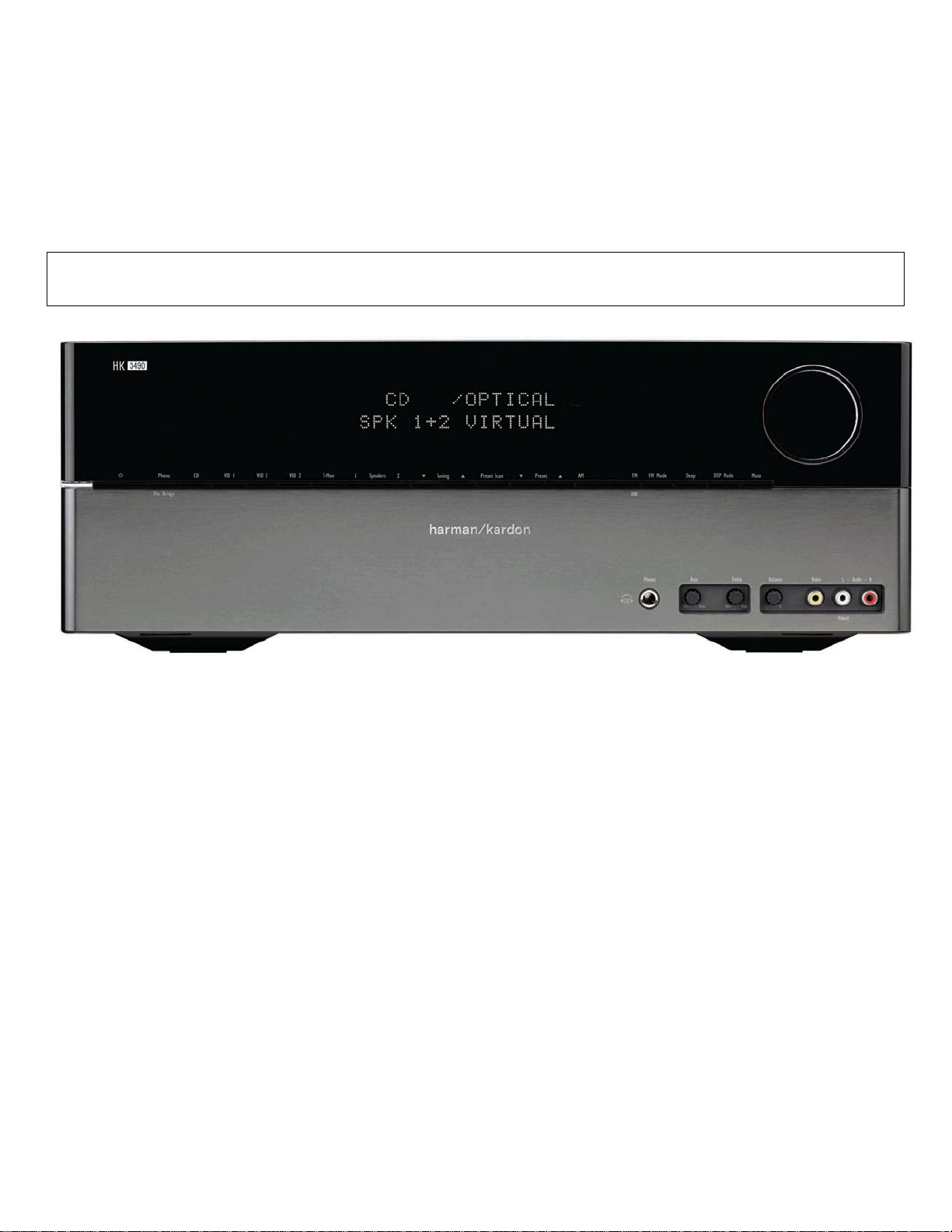
HK3490
STEREO RECEIVER
SERVICE MANUAL
ESD WAR N ING……………………………….2
LEAKAGE TESTING……………….…..…....3
BASIC SPECIFICATIONS…………………..4
PACKAGING…………………………….……5
FRO NT PANEL CO NTRO L S ………..…..…..6
REAR PANEL CONNECTIONS………….…8
REMOTE CONTROL FUNCTIONS……….11
CONNECTIONS/INSTALLATION………....14
OPERATION………………………...………21
TROUBLESHOOTING GUIDE…...……..…26
PROCESSOR RESET……………………....26
250 Crossways Park Dr.
CONTENTS
DISASSEM BLY…...…………………………..27
UNIT EXPLOD ED VI EW…………..…….…..30
EXPLODED VIEW PARTS LIST……………31
AMP BIAS ADJUSTMENT……………….…32
BLOCK DIAGRAM…………………………..33
PCB DRAWINGS……………………………34
ELECTRICAL PARTS LIST………..….……40
SEMICONDUCTOR PINOUTS…….………63
SCHEMATICS………….….……………….104
WIRING DIAGRAM…….….……………….108
harman/k ar don, Inc.
Released 2008 Woodbur y, New York 11797 Rev0 6/2008
Discontinued XXXX
Page 2
HK3490 harman/kardon
2
Some semiconductor (solid state) devices can be damaged easily by static electricity. Such components commonly are called
Electrostatically Sensitive (ES) Devices. Examples of typical ES devices are integrated circuits and some field effect transistors and
semiconductor "chip" components.
The following techniques should be used to help reduce the incidence of component damage caused by static electricity.
1. Immediately before handling any semiconductor component or semiconductor-equipped assembly, drain off any electrostatic charge on
your body by touching a known earth ground. Alternatively, obtain and wear a commercially available discharging wrist strap device,
which should be removed for potential shock reasons prior to applying power to the unit under test.
2. After removing an electrical assembly equipped with ES devices, place the assembly on a conductive surface such as aluminum foil, to
prevent electrostatic charge build-up or exposure of the assembly.
3. Use only a grounded-tip soldering iron to solder or unsolder ES devices.
4. Use only an anti-static solder removal device. Some solder removal devices not classified as "anti-static" can generate electrical charges
sufficient to damage ES devices.
5. Do not use freon-propelled chemicals. These can generate electrical change sufficient to damage ES devices.
6. Do not remove a replacement ES device from its protective package until immediately before you are ready to install it. (Most replacement
ES devices are packaged with leads electrically shorted together by conductive foam, aluminum foil or comparable conductive material.)
7. Immediately before removing the protective material from the leads of a replacement ES device, touch the protective material to the
chassis or circuit assembly into which the device will be installed.
CAUTION :
8. Minimize bodily motions when handling unpackaged replacement ES devices. (Otherwise harmless motion such as the brushing together
or your clothes fabric or the lifting of your foot from a carpeted floor can generate static electricity sufficient to damage an ES devices.
Be sure no power is applied to the chassis or circuit, and observe all other safety precautions.
Each precaution in this manual should be followed during servicing.
Components identified with the IEC symbol in the parts list are special significance to safety. When replacing a component identified with
, use only the replacement parts designated, or parts with the same ratings or resistance, wattage, or voltage that are designated in the
parts list in this manual. Leakage-current or resistance measurements must be made to determine that exposed parts are acceptably
insulated from the supply circuit before retuming the product to the customer.
Page 3
HK3490 harman/kardon
3
Before returning the unit to the user, perform the following safety checks :
1. Inspect all lead dress to make certain that
leads are not pinched or that hardware is not
lodged between the chassis and other metal
parts in the unit.
2. Be sure that any protective devices such as
nonmetallic control knobs, insulating fish-
papers, cabinet backs, adjustment and
compartment covers or shields, isolation
resistor-capacity networks, mechanical
insulators, etc. Which were removed for the
servicing are properly re-installed.
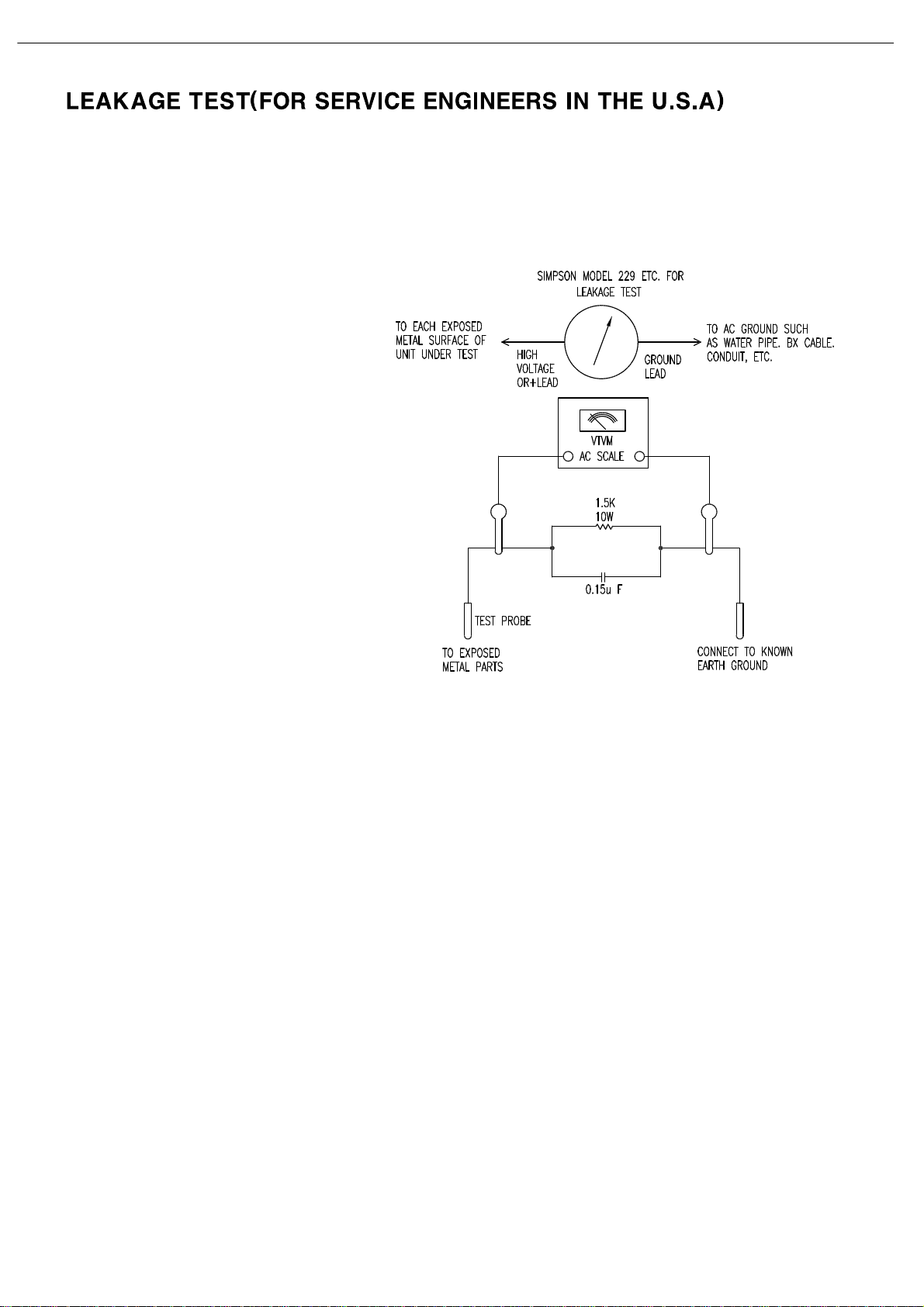
3. Be sure that no shock hazard exists ; check for leakage
current usingSimpson Model 229 Leakage Tester, standard
equipment item No. 21641, RCA Model WT540A or use
alternate method as follows : Plug the power cord directly
Into a 120 volt AC receptacle (do not use an Isolation
Transformer for this test). Using two clip leads, connect a
1500 ohms,10watt Resistor paralleledby a 0.15uFcapacitor,in series withall exposed metalcabinet parts anda known earthground, such
as a water pipe or conduit. Use a VTVM or VOM with 1000 ohms per volt, or higher sensitivity to measure the AC voltage drop across the
resistor. (See diagram) Move the resistor connection to each exposed metal part having a return path to the chassis (antenna, metal,
cabinet, screwheads, knobsand controlshafts, escutcheon, etc.) and measurethe ACvoltage dropacross the resistor. (Thistest shouldbe
performed withthe 0.35 volt RMS or more is excessiveand indicates apotential shock hazardwhich must be corrected before returning the
unit to the owner.
Page 4

29
HK 3490 TECHNICAL SPECIFICATIONS
Audio Section
Stereo Mode:
Continuous Average Power (FTC):
120 Watts per channel, 20Hz – 20kHz,
@ <0.07% THD, both channels driven into 8 ohms
150 Watts per channel, 20Hz – 20kHz
@ <0.2% THD, both channels driven into 4 ohms
Input Sensitivity/Impedance
Linear (High-Level): 200mV/47k ohms
Signal-to-Noise Ratio (IHF-A): 95dB
Frequency Response @ 1W (+0dB, –3dB): 10Hz –110kHz
High Instantaneous Current Capability (HCC): ±45 Amps
Transient Intermodulation
Distortion (TIM): Unmeasurable
Rise Time: 16 µsec
Slew Rate: 40V/µsec
FM Tuner Section
Frequency Range: 87.5 – 108.0MHz
Usable Sensitivity: IHF 1.3µV/13.5dBf
Signal-to-Noise Ratio: Mono/Stereo 73/72dB
Distortion: Mono/Stereo 0.3/0.4%
Stereo Separation: 40dB @ 1kHz
Selectivity: ±400kHz, 65dB
Image Rejection: >80dB
IF Rejection: >100dB
Tuner Output Level: 1kHz, ±100kHz, Dev 500mV
AM Tuner Section
Frequency Range: 520 – 1720kHz
Signal-to-Noise Ratio: >40dB
Usable Sensitivity: Loop 500µV/M
Distortion: 1kHz, 50% Mod 0.8%
Selectivity: ±10kHz, >25dB
Video Section
Television Format: NTSC/PAL/SECAM
Signal Format: Composite
Input Level: 1Vp-p
Input Impedance: 75 Ohms, unbalanced
Sync Polarity: Negative
Output Level: 1Vp-p
Output Impedance: 75 Ohms, unbalanced
Video Frequency Response: 10Hz – 10MHz
General
Power Requirement: AC 120V/60Hz
Power Consumption:
<
1W standby, 310 W maximum
(both channels driven)
Dimensions: (Product) (Shipping)
Width: 17-3/8" (442mm) 22" (560mm)
Height: 6-3/8" (163mm) 10-5/8" (270mm)
Depth: 15" (382mm) 18-5/16" (465mm)
(Product) (Shipping)
Weight: 23 lb (10.4kg) 27.3 lb (12.4kg)
Depth measurement includes knobs, buttons and terminal connections.
Height measurement includes feet and chassis.
All features and specifications are subject to change without notice.
Harman Kardon is a trademark of Harman International Industries, Incorporated, registered in the
United States and/or other countries. Designed to Entertain and The Bridge logo are trademarks
of Harman International Industries, Incorporated.
CEA is a registered trademark of the Consumer Electronics Association.
Dolby is a registered trademark of Dolby Laboratories.
iPod is a trademark of Apple Inc., registered in the U.S. and other
countries. iPhone and Shuffle are trademarks of Apple Inc.
XM and XM Ready are registered trademarks of XM Satellite Radio.
4
HK3490 harman/kardon
Please register your product at www.harmankardon.com. Note: You’ll need your serial number.
At the same time, you can choose to be notified about new products and/or special promotions.
Page 5
HK3490
5
visit www.harmankardon.com
HK 3490
Page 6

7
FRONT-PANEL CONTROLS
6
HK3490 harman/kardon
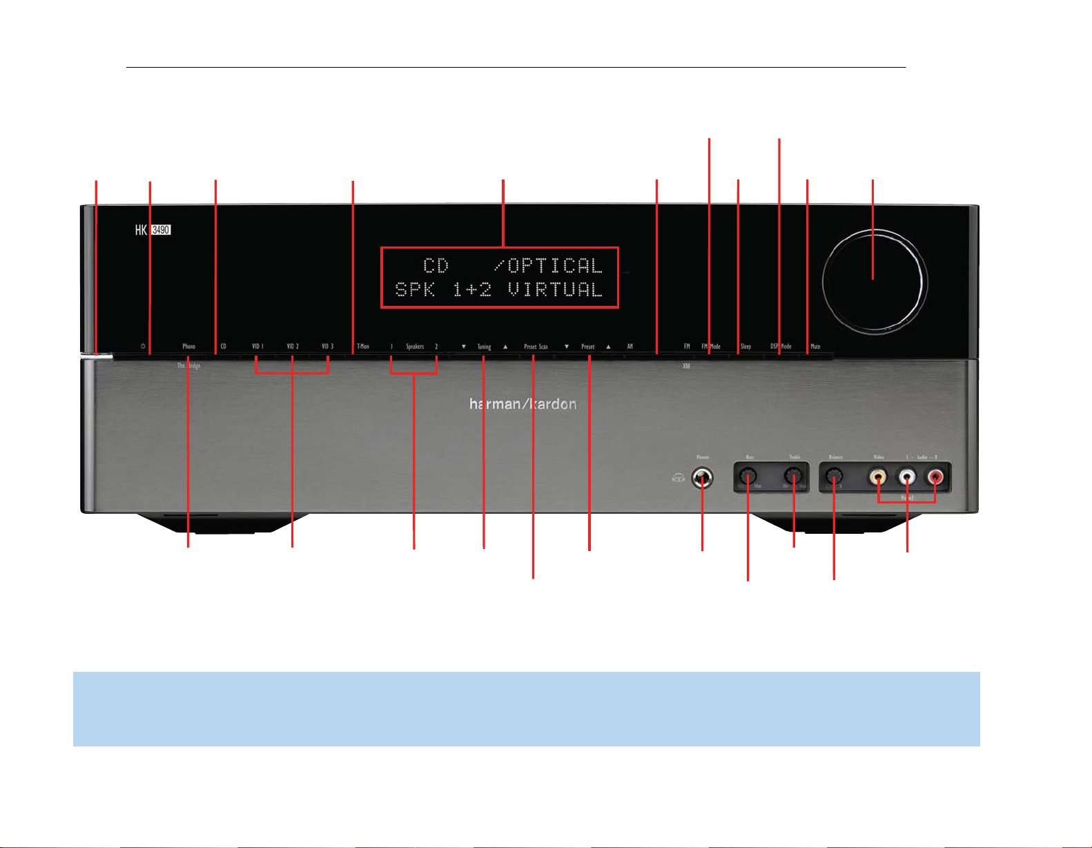
Power Indicator: This LED has two modes. When power is
turned off, the LED is amber to indicate that the receiver is plugged
in and ready to be turned on. When the receiver is turned on, the
LED turns white.
Power Switch: This electrical switch turns the receiver on for
playback, or leaves it in Standby mode for quick turn-on using the
remote control.
Phono/The Bridge Source Selector: Press this button to select
a turntable connected to the Phono Inputs as the source. Press it again
to select an iPod docked in the optional Harman Kardon The Bridge II
docking station as the source. Each additional press switches between
these two sources.
CD Source Selector: Press this button to select the device
connected to the CD Inputs as the source.
Video Source Selectors: Press any of these buttons to select
the device connected to the corresponding Audio and Video Inputs for
playback. Remember to turn on the source device, to connect the Video
Monitor Output to your video display and to turn on your video display
and select the correct Video Input.
NOTE: The Video 3 source device may be connected to either
the front- or rear-panel connectors. To select the desired device,
press the Video 3 Source Selector repeatedly to toggle between
the front and rear inputs.
Tape Source Selector: Press this button to select the device
connected to the Tape/CDR Audio Inputs as the source. If you are
making a recording using a three-head tape deck or another unit with
off-head playback, you will be able to monitor the recording as it is
being made.
Speaker 1/2: Press the left side of this button to enable the
HK 3490 to output audio to the speakers connected to the Speaker 1
Outputs, and press the right side of the button to enable the Speaker 2
Outputs. You may enable or disable both sets of speaker outputs
simultaneously. This feature is a convenient way of hearing audio in
more than one room at a time, although the same source material will
be played through both sets of speakers.
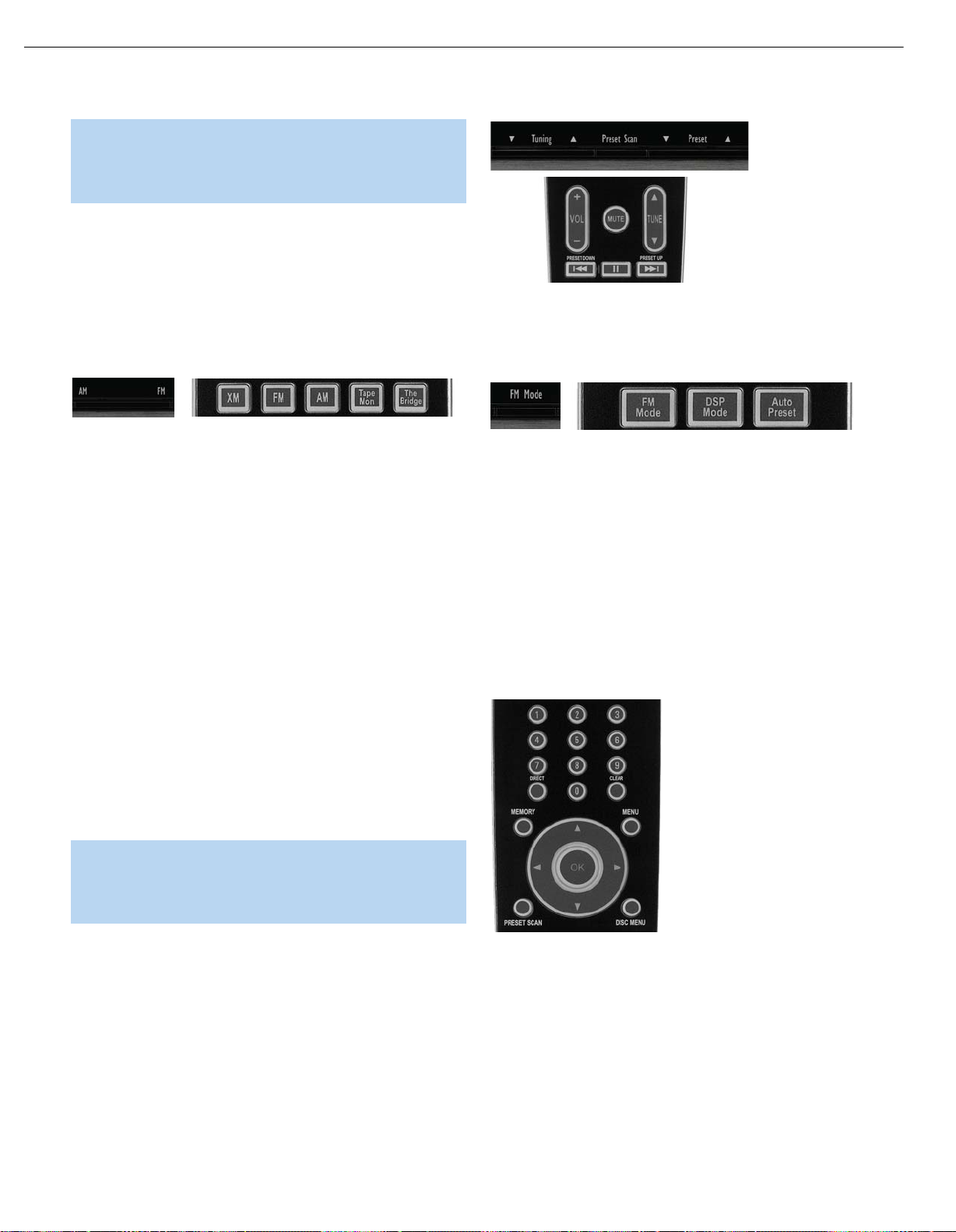
Tuning: Press either side of this button to tune a radio station. Tap the
button briefly to tune one frequency step at a time, or press and hold
the button to seek the next frequency with an acceptably strong signal.
Preset Scan: Press this button once to scan through the stations
you have previously programmed as presets. Each station will play for
five seconds before the tuner skips to the next preset station. Press the
button a second time to select the current station. If no presets have
been programmed, the 0 PRESET message will be displayed. When
listening to XM
information: channel name and number, category, artist and song title.
®
Radio, each press displays the current playback
Preset Stations: Press this button to select a preset radio station.
If no presets have been programmed, the 0 PRESET message will be
displayed. When listening to XM Radio, each press changes the preset
number within the current lettered bank.
Tuner Band: Press this button to select the tuner as the source, or
to select the AM (left side of button) or FM (right side of button) band.
Each press of the FM side of the button toggles between the FM and
XM bands.
FM Mode: This button toggles between Stereo and Mono modes
when an FM station is tuned. Mono mode may improve reception of
weaker signals. When listening to XM radio, each press of this button
changes the channel search mode as follows:
‹/›
• All Channel Search: The Tuning Buttons and the
the remote may be used to tune any channel.
‹/›
• Preset Search: The
change the lettered bank of presets.
• Category Search: The Tuning Buttons and the
remote may be used to tune a channel within the current category.
Buttons on the remote may be used to
‹/›
Buttons on
Buttons on the
Sleep: Press this button to activate the sleep timer, which shuts off the
receiver after a programmed period of time up to 90 minutes.
DSP Mode: Each press of this button switches the digital signal
®
processing mode as follows: Dolby
Speaker Reference, Stereo.
Virtual Speaker Wide, Dolby Virtual
Mute: Press this button to mute the HK 3490’s speaker and headphone
outputs temporarily. To end the muting, press this button or adjust the
volume. Muting is also canceled when the receiver is turned off.
Volume Control: Turn this knob to raise or lower the volume, which
will be shown in decibels (dB) in the Message Display.
Headphone Jack: Plug a 1/4" headphone plug into this jack for
private listening.
Bass Control: Turn the knob clockwise to boost low-frequency output
by up to 10dB, or counterclockwise to cut low-frequency output by up
to 10dB. Set the control to suit your taste and room acoustics.
Treble Control: Turn the knob clockwise to boost high-frequency
output by up to 10dB, or counterclockwise to cut high-frequency output
by up to 10dB. Set the control to suit your taste and room acoustics.
Balance Control: Turn the knob to adjust the relative volume of the
left and right channels, which affects imaging and can compensate for
room characteristics.
NOTE: To use the Bass, Treble or Balance Controls, gently press
the knob until it unlatches. When finished, press the knob again
to lock it.
Video 3 A/V Inputs: Connect a source component that will only be
used temporarily to these jacks, such as a camera or game console, or
connect an iPod using the supplied audio/video cable.
Message Display: Various messages appear in this display in
response to commands. In normal use, the Upper Line will display the
current source and audio input (analog or one of the digital audio
inputs). The Lower Line displays the current speaker group (if any are
active) and the DSP mode. Other messages may appear for some
sources, such as The Bridge docking station and the tuner.
Page 7
7
HK3490 harman/kardon
Power
Indicator
Power
Switch
CD Source
Selector
Tape Source
Selector
Message Display
Tuner
Band
FM Mode
Sleep
DSP Mode
Mute
Volume
Control
Phono/The Bridge
Source Selector
Video Source
Selectors
1 Speakers 2
Tuning
Preset Scan
Preset
Stations
Headphone
Jack
Bass
Control
Treble
Control
Video 3
A/V Inputs
Balance
Control
NOTE: To make it easier to follow the instructions throughout the manual that refer to this illustration, a copy of this page may be downloaded from the Product Support section at
www.harmankardon.com.
Page 8

8
HK3490 harman/kardon
REAR-PANEL CONNECTIONS
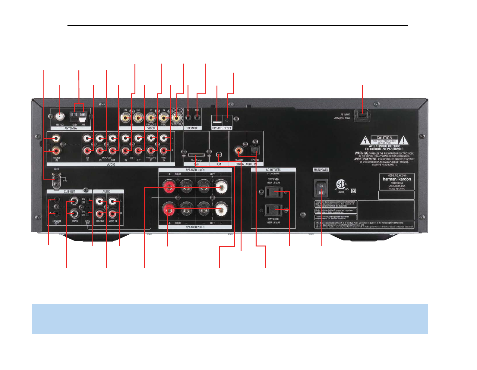
AM and FM Antenna Terminals: Connect the included AM and
FM antennas to their respective terminals for radio reception.
Video 1, Video 2 and Video 3 Audio/Video Inputs: These
jacks may be used to connect your video-capable source components
(e.g., VCR, DVD player, cable TV box) to the receiver.
NOTE: The Video 3 source has inputs on both the front and
rear panels of the HK 3490, and you may connect different
devices to each set of inputs. To select between the two sets
of inputs, press the Video 3 Source Selector repeatedly.
Video 1 Audio/Video Outputs: These jacks may be used to
connect your VCR or another recorder.
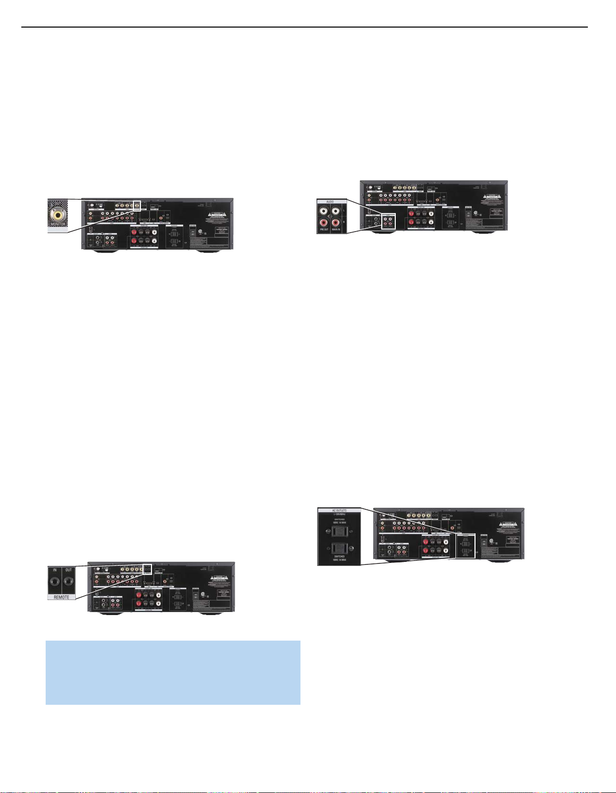
Video Monitor Output: If some of your sources use video
connections, connect the Video Monitor Output to the corresponding
input on your television or video display to view the sources. No video
signal will be available when an audio-only source input, such as CD
or Tape, is selected.
Remote Infrared (IR) Input and Output: When the remote
IR receiver on the front panel is blocked, such as when the HK 3490
is placed inside a cabinet, connect an optional IR receiver to the Remote
IR Input jack for use with the remote control. The Remote IR Output may
be connected to the Remote IR Input of a compatible source device
(or other product) to enable remote control through the HK 3490. When
several source devices are used, connect them in “daisy chain” fashion.
Update Port: This connection is for authorized service personnel only.
It is used with a proprietary device in the event that a software update
for the HK 3490 becomes available in the future. Do not make any
connections to it.
Reset Button: In the event that the HK 3490 operates erratically, a
system reset may restore proper functionality. Place the unit in Standby
mode by pressing the Power Switch so that the Power Indicator turns
amber. Then use a fine-point pen or other similar object to press the
Reset Button.
The Bridge/DMP Input: Connect the optional Harman Kardon
or docking station to this input for use with
your iPod, iPod touch or iPhone (not included). Make sure the receiver
is turned off (in Standby mode) when connecting The Bridge or
The Bridge II docking station.
XM Antenna Jack: Plug in an XM antenna module here. The XM
antenna module is purchased separately, and should specify that it is for
home use with an XM Ready product. You will need to subscribe to the
XM service, which is available separately, and activate the service for
your antenna module. (XM service is not available in Alaska and Hawaii.)
Coaxial and Optical Digital Audio Inputs: If a source has a
compatible digital audio output, connect it to one of these jacks for
improved audio performance. Use only one type of digital audio
connection for each source.
Switched AC Accessory Outlets: You may plug the AC power
cord of one source device into each of these outlets, and it will turn on
whenever you turn on the receiver. Do not use sources that consume
more than 100 watts of power per outlet.
Speaker 1 and 2 Outputs: Use two-conductor speaker wire to
connect each set of terminals to the correct speaker. Observe the
correct polarity (positive and negative connections). Always connect the
positive lead to the red or white terminal on the receiver and the red
terminal on the speaker. Connect the negative lead to the black terminal
on both the receiver and the speaker. Use the Speaker 1/2 Selectors
on the front panel or remote to select either or both pairs of speakers
for playback.
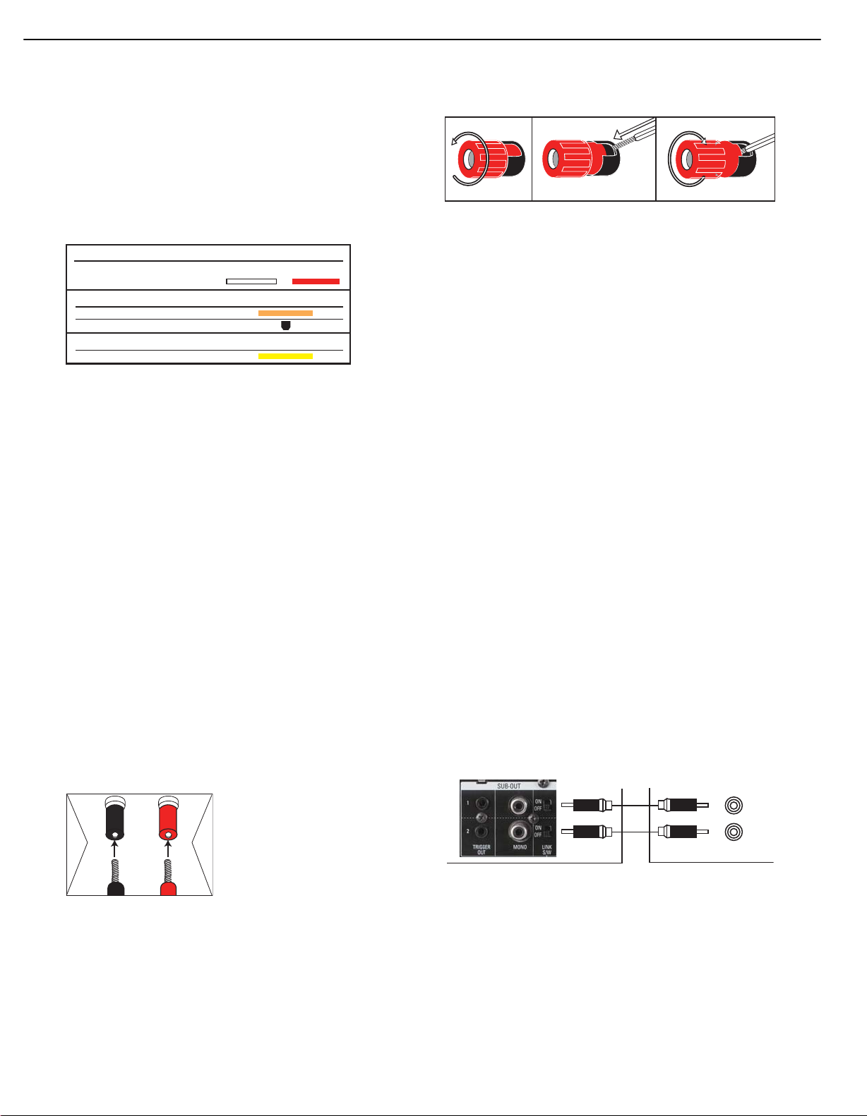
Subwoofer Outputs: If you have a powered subwoofer, connect
these jacks to the line-level inputs on the subwoofer. The same fullrange signal is output through both jacks. Thus, you have the option
of connecting each jack to the line-level input on a separate subwoofer
or to use the full-range outputs to feed a remote room in a distributedaudio application. If you have only one subwoofer with a single line-level
input, connect it to the right Subwoofer Output on the HK 3490.
Subwoofer Trigger Outputs: Connect these outputs to a
compatible trigger input on the subwoofer connected to the Subwoofer
Output immediately to the right of the Trigger Output. Consult the
owner’s manual for the subwoofer to set its trigger input correctly, and
the subwoofer will automatically turn on or off when the HK 3490 is
turned on or off. In addition, the Trigger Outputs are used with the
Subwoofer Link Switches to conserve energy by powering off the
subwoofer’s amplifier when it is not needed. The Subwoofer Trigger
Outputs send a signal of 15 volts DC.
Subwoofer Link Switches: Each switch affects the subwoofer
connected to the jack immediately to the left of the switch. To use the
switch, first connect the corresponding Subwoofer Trigger Output to
a compatible trigger input on the subwoofer, and make sure the
subwoofer’s instructions are followed to activate its trigger input. When the
Link Switch is on, the HK 3490 will remove the trigger signal whenever
the corresponding pair of main speakers is not in use, thereby conserving
energy that would otherwise be used to maintain the subwoofer’s amplifier
in Standby mode. This feature is activated any time no signal is present at
the main speaker outputs, including when the Speaker 1/2 Switch turns
off both speaker pairs, when the HK 3490’s output is muted, or when the
headphones are plugged in. See Table A2 in the appendix for details.
Main-Amp Inputs and Preamp Outputs: These jacks are
normally connected directly to each other with an included jumper.
Some devices, such as equalizers and some loudspeaker systems,
require connection between the Preamp Outputs and Main-Amp
Inputs, in which case the jumpers should be removed and stored in a
safe place for future use. You may also remove the jumpers if you wish
to connect the Preamp Outputs to an external amplifier, or if you wish
to connect another device’s line-level output directly to the HK 3490’s
power amplifier for a special application.
AC Power Cord: After you have made all other connections, plug
the AC power cord into an unswitched outlet.
9
Tape Outputs: These jacks may be used to connect your CDR or
another audio-only recorder.
9
Page 9
9
HK3490 harman/kardon
Phono
AM Antenna
FM Antenna
CD
Inputs
Tape/CDR
Inputs
Tape/CDR
Outputs
Video 1
A/V
Inputs
Video 1
A/V
Outputs
Video 2/
DVD
Inputs
Video 3
A/V
Inputs
Video
Monitor
Output
Remote
IR
Input
Remote
IR
Output
Update
Port
Reset
Button
AC Power
Cord
Subwoofer
Trigger
Outputs
Subwoofer
Outputs
Subwoofer
Link
Switches
Preamp
Outputs
Main-Amp
Inputs
Speaker 1
Outputs
Speaker 2
Outputs
XM Antenna
Jack
The Bridge
DMP Connector
Switched AC
Accessory
Outlets
Digital
Audio Inputs
Main
Power
Switch
NOTE: To make it easier to follow the instructions throughout the manual that refer to this illustration, a copy of this page may be downloaded from the Product Support section at
www.harmankardon.com.
Page 10

11
CD and Tape Inputs: These jacks may be used to connect your
audio-only source components (e.g., CD player, tape deck). Do not
connect a turntable to these jacks unless you are using the turntable
with a phono preamp. When your recorder features three-head or
off-head playback, you may monitor a recording as it is being made.
Phono Inputs and Ground: Connect the outputs of your turntable
or tonearm to these jacks, and connect the ground wire from the
turntable to this Ground Connector to reduce system hum. Only movingmagnet (MM-type) cartridges are compatible with the Phono Inputs. If
your turntable is equipped with its own onboard phono preamp, you
may connect it to any of the HK 3490’s other audio inputs.
Main Power Switch: This mechanical switch turns the power supply
on or off. It is usually left turned on (push the rocker in at the top), and
cannot be turned on using the remote control. Turn this switch off when
connecting or disconnecting source devices or loudspeakers to prevent
any possibility of damage to components resulting from an unexpected
power surge.
REAR-PANEL CONNECTIONS
10
HK3490 harman/kardon
Page 11

11
HK3490 harman/kardon
REMOTE CONTROL FUNCTIONS
The HK 3490 remote is capable of controlling six devices, including the
HK 3490 itself. The remote is preprogrammed at the factory to operate
most Harman Kardon DVD, CD and CDR players. Each time you wish to
use the codes for any component, first press its Selector Button. This
changes the button functions to the appropriate codes.
Phono: Controls only the HK 3490 when a turntable is in use.
Video 1: Controls the Harman Kardon DMC 1000 digital media server.
Video 2 and 3: Controls DVD players. Each source uses a slightly
different code set. Test the remote on your Harman Kardon DVD player,
and refer to Table A3 in the appendix. Connect the DVD player to the
source inputs corresponding to the code set that correctly operates the
device.
Tape: Controls CD recorders.
CD: Controls CD players.
AM/FM: Controls the HK 3490 and its internal tuner only.
XM: Controls the HK 3490 and its internal tuner only.
The Bridge: When an optional Harman Kardon The Bridge or The
Bridge II docking station is connected and an iPod (not included) is
docked, this mode controls navigation and playback of materials stored
on the iPod.
The functions specific to the HK 3490 are always available: Main Power
On and Off, Speaker 1/2, source selection, Mute, Sleep, Dimmer and
the Volume Controls.
Any given button may have different functions, depending on which
component is being controlled. Some buttons are labeled with these
functions. For example, the Track Skip Buttons are labeled with the
transport control icons printed on the buttons themselves, and these
functions are active when a CD or DVD player is in use. The Preset
indications appear above these buttons, and those commands are
active when the HK 3490’s tuner is in use. See the appendix for
listings of the different functions for each type of component.
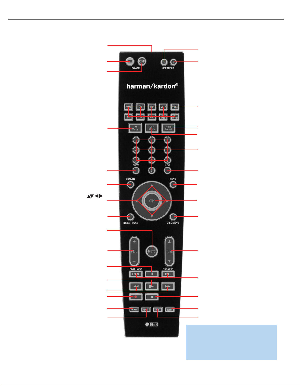
IR Transmitter Lens: As buttons are pressed on the remote,
infrared codes are emitted through this lens. Make sure it is pointing
toward the component being operated.
Power Off Button: Press this button to turn off the HK 3490 or
another device.
Power On Button: Press this button to turn on the HK 3490 or
another device.
Speaker 1/2: Press the Speaker 1 Button to enable the HK 3490 to
output audio to the speakers connected to the Speaker 1 Outputs, and
press the Speaker 2 Button to enable the Speaker 2 Outputs. You may
enable or disable both sets of speaker outputs simultaneously. This
feature is a convenient way of hearing audio in more than one room at
a time, although the same source material will be played through both
sets of speakers.
Source Selectors: Press one of these buttons to select a source
device, which is a component where a playback signal originates, e.g.,
DVD, CD or the tuner. This will also turn on the receiver and switch the
remote to the codes that operate the source device.
NOTE: The Video 3 source device may be connected to either
the front- or rear-panel connectors. To select the desired device,
press the Video 3 Source Selector repeatedly. The VIDEO 3
message indicates that the rear-panel inputs are active, and the
VIDEO F message indicates the front-panel inputs have
been selected.
FM Mode: This button toggles between Stereo and Mono modes
when an FM station is tuned. When XM Radio is in use, each press
of this button changes the search mode, which controls how the
‹/›
Buttons operate.
• Preset Search Mode: Each press of the
the lettered bank of preset stations. Each press of the
changes the numbered preset within the bank.
• Category Search Mode: Each press of the
to the next category of stations, e.g., Decades.
• All Channel Search Mode: The
⁄/¤
Buttons change the channel number.
‹/›
Buttons changes
‹/›
‹/›
Buttons do nothing. The
⁄/¤
Buttons
Buttons jumps
DSP Mode: Each press of this button switches the digital signal
processing mode as follows: Dolby Virtual Speaker Wide, Dolby Virtual
Speaker Reference, Stereo.
Auto Preset: The Auto Preset feature enables you to automatically set
presets for all available FM radio stations in your area with a single button
press. To start the process, make sure the FM tuner has been selected
as the source. Press and hold this button. The AUTO PRESET message
will appear as the HK 3490 tuner scans through all FM stations with
acceptable signal quality and programs them into the presets. If there are
fewer than 30 stations, the tuner will cycle through again, filling up the
higher preset slots with the same stations. The scan will stop when all
30 presets have been filled, or after two scans through the FM band.
Numeric Keys: Use these buttons to enter radio station frequencies
when using the tuner (after pressing the Direct Button, except for XM), or
to select station presets.
Direct: Press this button before using the Numeric Keys to directly
enter a radio station frequency. It is not necessary to press this button
before using the Numeric Keys to enter an XM Radio channel.
Clear: Press this button to clear a radio station frequency you have
started to enter.
Memory: After you have tuned a particular radio station, press this
button, then the Numeric Keys, to save that station as a radio preset.
When XM Radio is in use, programming presets is somewhat different.
First, tune to the desired channel. Then, press the Memory Button and
‹/›
the preset indication will flash. Use the
desired preset bank (A through E), and then use the
Buttons to select the
⁄/¤
Buttons
12
12
Page 12
12
HK3490 harman/kardon
IR Transmitter Lens
Speaker 1
Power On
Power Off
FM Mode
Direct
Memory
Navigation
Speaker 2
Source Selectors
Auto Preset
DSP Mode
Numeric Keys
Clear
Menu
OK
Preset Scan
Mute
Volume
Controls
Pause
Play
Fast Search
Record
Dimmer
Repeat
Disc Menu
Tuning
Preset Stations
Selectors/Track Skip
Stop
Sleep
A-B
NOTE: To make it easier to follow the
instructions throughout the manual that refer to
this illustration, a copy of this page may be
downloaded from the Product Support section
at www.harmankardon.com.
Page 13

13
HK3490 harman/kardon
REMOTE CONTROL FUNCTIONS
to select a numbered location (1 through 8) within the bank. Press the
Memory Button to complete the process and let the HK 3490 return to
normal operation.
Menu: This button has no effect on the HK 3490, but is used with
some source devices to access the source’s setup menus.
Navigation (
in use, the
or the lettered bank of presets. As described above, press the FM Mode
Button to select a search mode. Use the
numbered preset within a bank when in Preset Search mode, or to
change the channel sequentially when in All Channel Search mode.
These buttons have no other effect on the HK 3490, but are used to
make selections within the on-screen menu system for some source
devices. The OK Button transmits the Random Play command when
used with CD players.
⁄/¤
‹/›
Buttons may be used to change the channel category
›
/‹/
) and OK Buttons: When XM Radio is
⁄/¤
Buttons to change the
Preset Scan: Press this button once to scan through the stations
you have previously programmed as presets. Each station will play for
five seconds before the tuner skips to the next preset station. Press the
button a second time to select the current station. If no presets have been
programmed, the 0 PRESET message will be displayed. When XM Radio
is in use, this button has nothing to do with preset stations. Instead, each
press of this button changes the information displayed on the front panel
as follows: channel name and number, channel category, artist name and
song title.
Button repeatedly until the PRESET SEARCH message appears in the
‹/›
Message Display, and use the
bank. Then use the Preset Stations Selectors to select the numbered
preset within the bank.
Buttons to change to the desired
Stop, Record, Pause and Play: These transport controls have no
effect on the receiver, but are used to control compatible Harman Kardon
DVD and CD players.
Fast Search: The Fast Search function is available with compatible
Harman Kardon DVD and CD players.
Dimmer: Press this button to partially or fully dim the front-panel display.
Repeat (V. Mode): This button has no effect on the HK 3490, but
issues the Repeat command when used with DVD and CD players. On
some remotes this button is labeled “V. Mode,” but it still issues the
Repeat command.
A-B (Source): This button has no effect on the HK 3490, but issues
the Repeat A-B command when used with DVD and CD players with
that feature. On some remotes, this button is labeled “Source,” but it
still issues the Repeat A-B command.
Sleep: Press this button to activate the sleep timer, which shuts off
the receiver after a programmed period of time up to 90 minutes.
Disc Menu: This button has no effect on the HK 3490, but is used
with some DVD players to access the DVD disc’s menus.
Volume Controls: Use this control to raise or lower the volume,
which will be shown in decibels (dB) in the Message Display.
Mute Button: Press this button to mute the HK 3490’s speaker and
headphone outputs temporarily. To end the muting, press this button or
adjust the volume. Muting is also canceled when the receiver is turned
off. When the Subwoofer Trigger Output is connected to the correct
input on the subwoofer, and the corresponding Subwoofer Link Switch
is on, muting the HK 3490 will remove the trigger signal, turning off
the subwoofer’s amplifier to conserve energy. When normal listening
resumes, the trigger signal will be reactivated, turning on the subwoofer.
Tuning: Use this control to tune a radio station. Tap one end of the
button briefly to tune one frequency step at a time, or press and hold it
to seek the next frequency with an acceptably strong signal. When XM
Radio is in use, the digitally tuned channels are always of acceptable
strength, and thus there is no seek function, although pressing and
holding the Tuning Buttons scans through the channels faster. When the
FM Mode Button has been used to activate Category Search Mode, the
Tuning Buttons will only tune channels within the current category. Press
the FM Mode Button until All Channel Search Mode has been selected
to tune any channel.
Preset Stations Selectors/Track Skip: Press these buttons
to select a preset radio station, or to change tracks or chapters on
compatible Harman Kardon DVD and CD players. XM presets are stored
in one of five lettered banks. To switch banks, press the FM Mode
14
Page 14
12 3
+
Audio Connections
Left Right
Front (FL/FR)
Digital Audio Connections
Coaxial
Optical Input
Video Connections
Composite
14
HK3490 harman/kardon
CONNECTIONS
There are different types of audio and video connections used to
connect the receiver to the speakers and video display, and to connect
the source devices to the receiver. To make it easier to keep them all
straight, the Consumer Electronics Association has established a CEA
color-coding standard. Table 1 may be helpful to you as a reference
while you set up your system.
Table 1 – Connection Color Guide
®
Figure 2 – Binding-Post Speaker Terminals With Bare Wires
The HK 3490 features two sets of speaker connections, with each set
allowing connection of a left and right loudspeaker. This allows you to
place a second set of speakers in another room, or even outdoors,
when weather-resistant loudspeakers are used. You may play both sets
of speakers simultaneously, one set at a time or neither set when using
the headphones or making recordings. Use the Speaker 1/2 Buttons to
activate or deactivate each pair of speakers. It is not possible to select
different sources for each speaker pair.
Types of Connections
This section will briefly review different types of cables and connections
that you may use to set up your system.
Speaker Connections
Speaker cables carry an amplified signal from the receiver’s speaker
terminals to each loudspeaker. Speaker cables contain two wire
conductors, or leads, inside plastic insulation. The two conductors are
usually differentiated by using different colors, or stripes, or by adding a
ridge to the insulation. Sometimes the wires are different colors, one
being copper red and the other silver.
The differentiation is important because each speaker must be connected
to the receiver’s Speaker-Output terminals using two wires, one positive
(+) and one negative (–). This is called speaker polarity. It’s important
to maintain the proper polarity for all speakers in the system. If some
speakers have their negative terminals connected to the receiver’s
positive terminals, performance can suffer, especially for the low
frequencies.
Always connect the positive terminal on the loudspeaker, which is usually
colored red, to the positive terminal on the receiver, also colored red.
Similarly, always connect the black negative terminal on the speaker to
the black negative terminal on the receiver.
Subwoofer
The subwoofer is a specialized type of loudspeaker used to play only
the low frequencies (bass), which require much more power than the
other speaker channels. To obtain the best results, most speaker
manufacturers offer powered subwoofers, in which the speaker contains
its own amplifier on board. Usually, a line-level (nonamplified) connection
is made from the receiver’s Subwoofer Output to a corresponding jack
on the subwoofer, as shown in Figure 3, but sometimes the subwoofer
is connected to the receiver using the left and right speaker outputs,
then the left and right speakers are connected to terminals on the
subwoofer. The same full-range signal is output through both jacks.
Thus, you have the option of connecting each jack to the line-level input
on a separate subwoofer. If you have only one subwoofer with a single
line-level input, connect it to the right Subwoofer Output on the HK 3490.
Connect the Subwoofer Trigger Output for each subwoofer to the
corresponding trigger input on its amplifier. This enables the subwoofer to
turn on or off together with the HK 3490. To further conserve energy,
when the trigger connection is made, turn the Subwoofer Link Switch on
to turn the subwoofer off when the corresponding pair of main speakers
are not being used, such as during muting, when headphones are being
used, or when the main speakers are turned off using the Speaker 1/2
switch.
The HK 3490 uses binding-post speaker
terminals that can accept banana plugs
or bare-wire cables.
Banana plugs are simply plugged into the
hole in the middle of the terminal cap.
See Figure 1.
Figure 1– Binding-Post Speaker Terminals With Banana Plugs
Bare-wire cables are installed as follows (see Figure 2):
1. Unscrew the terminal cap until the pass-through hole in the collar
is revealed.
2. Insert the bare end of the wire into the hole.
3. Screw the cap back into place until the wire is held snugly.
L
R
Subwoofer
Figure 3 – Subwoofer
Connecting Source Devices to the HK 3490
The HK 3490 is designed to process audio and video input signals,
playing back the audio and displaying the video on a television or
monitor connected to it. These signals originate in what are known as
“source devices,” including your DVD player, CD player, DVR (digital
video recorder) or other recorder, tape deck, game console, cable or
satellite television box, or MP3 player. Although the tuner is built into the
15
Page 15
A
Optical
Optical digital
audio cable
Coaxial
Coaxial digital
audio cable
15
HK3490 harman/kardon
CONNECTIONS
HK 3490, it also counts as a source, even though no external
connections are needed, other than the FM and AM antennas and
the XM module.
Separate connections are required for the audio and video portions
of the signal.
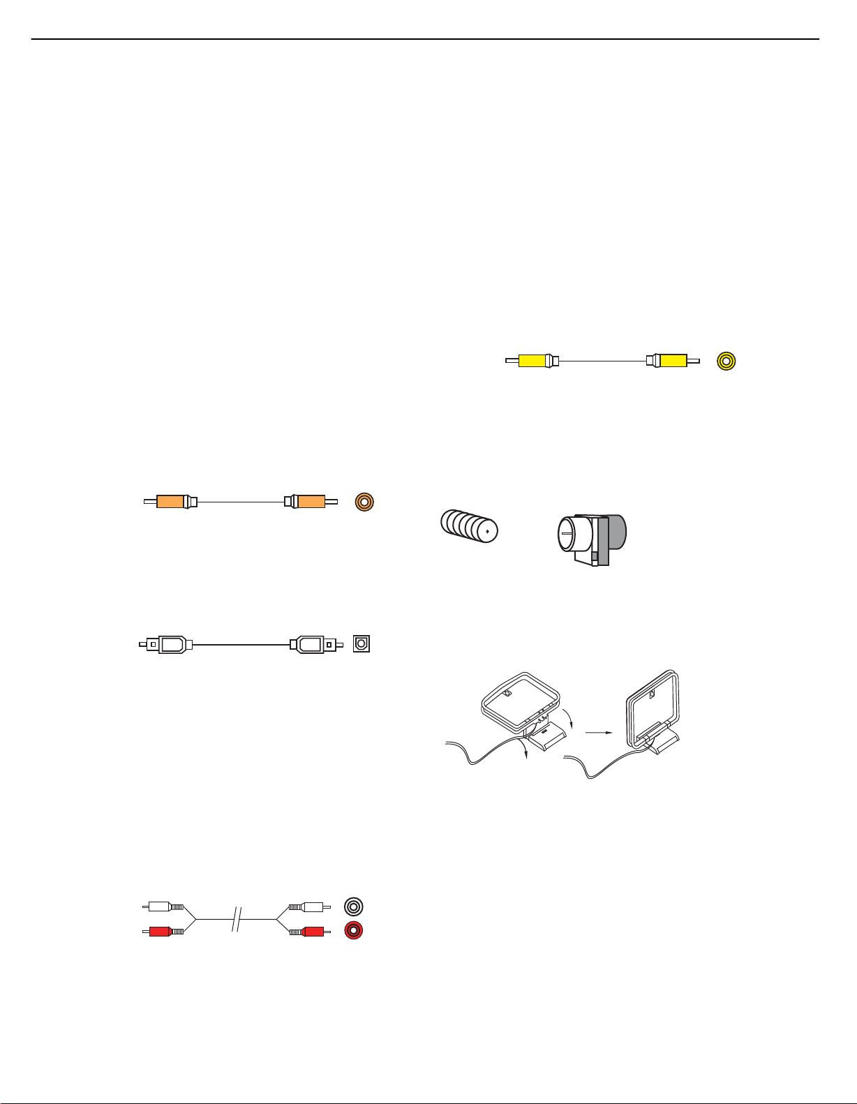
Audio Connections
There are two formats for audio connections: digital and analog. Digital
audio signals offer improved quality, free of distortion and with greater
detail and presence. The HK 3490 uses two types of digital audio
connections: coaxial and optical. Either type of digital audio connection
may be used for each source device, but never both simultaneously for
the same source. However, it’s alright to make both analog and digital
audio connections to the same source.
Digital Audio
Coaxial digital audio jacks are usually color-coded in orange. Although
they look similar to analog jacks, they should not be confused, and you
should not connect coaxial digital audio outputs to analog inputs or
vice versa. See Figure 4.
Video Connections
Although some sources only produce an audio signal (e.g., CD player,
tape deck), many sources output both audio and video signals (e.g.,
DVD player, cable television box, HDTV tuner, satellite box, VCR, DVR).
In addition to the audio connection, make a video connection for each
of these sources.
The composite video jack is usually color-coded yellow, and looks like
an analog audio jack, although it is important never to confuse the two.
Do not plug a composite video cable into an analog audio jack, and
vice versa. Both the chrominance (color) and luminance (intensity)
components of the video signal are transmitted using a single cable.
See Figure 7.
Composite
video cable
Figure 7 – Composite Video
Composite video
Antennas
The HK 3490 uses separate terminals for the included FM and AM
antennas that provide proper reception for the tuner.
The FM antenna uses a 75-ohm F-connector. See Figure 8.
Figure 4 – Coaxial Digital Audio
Optical digital audio connectors are normally covered by a shutter to
protect them from dust. The shutter opens as the cable is inserted. Input
connectors are color-coded using a black shutter, while outputs use a
gray shutter. See Figure 5.
Figure 5 – Optical Digital Audio
Analog Audio
Analog connections require two cables, one for the left channel (white)
and one for the right channel (red). These two cables are often attached
to each other for most of their length. See Figure 6. Most sources that
have digital audio jacks also have analog audio jacks, although some
older types of sources, such as tape decks, have only analog jacks. For
sources that are capable of both digital and analog audio, you may wish
to make both connections. If you wish to record materials from DVDs
or other copy-protected sources, you may only be able to do so using
analog connections. Remember to comply with all copyright laws if you
choose to make a copy for your own personal use.
nalog audio
cable (RCA)
Figure 6 – Analog Audio
L
R
Figure 8 – FM Antenna
The AM loop antenna needs to be assembled. Connect the two leads
to the spring terminals on the receiver. The AM antenna leads are
polarized, and it is important to color-match the leads and terminals
to maintain the proper polarity. See Figure 9.
Figure 9 – AM Antenna
To enjoy XM satellite radio, purchase an XM antenna module designed
for use with XM Ready devices and a subscription to the XM service.
We recommend the XM Mini-Tuner and Home Dock Bundle, available
at www.xmradio.com. The older Connect-and-Play module is also
compatible with the HK 3490, but it may no longer be available in
your area.
An XM Ready-compatible module uses the special connector on
the HK 3490’s rear panel that allows you to use the receiver’s tuner,
including its 40 preset station locations and remote control. Although
you may use a module with standard audio connections, which may
be indicated for “car and home use,” you will not be able to enjoy the
HK 3490’s ease of control.
16
Page 16
HK 3490
FM
AM
XM
HK 3490
Right (Spkr 1) Right (Spkr 2) Left (Spkr 1)Left (Spkr 2)
16
HK3490 harman/kardon
INSTALLATION
You are now ready to connect your various components to your receiver.
Before beginning, make sure that all components, including the HK 3490,
are turned completely off and their power cords are unplugged. Don’t
plug in any of the power cords until you have finished making all
of your connections.
The receiver generates heat while it is on. Select a location that leaves
several inches of space on all sides of the receiver. It is preferable to
avoid completely enclosing the receiver inside a cabinet. It is also
preferable to place components on separate shelves rather than directly
on top of the receiver. Some surface finishes are delicate. Try to select
a location with a sturdy surface finish.
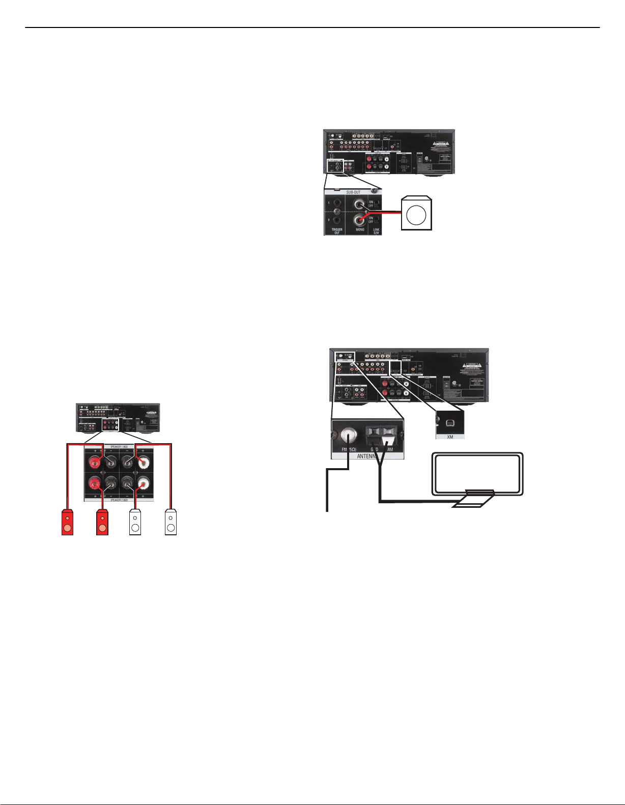
Step One – Connect the Speakers
If you have not yet done so, place your speakers in the listening room
as described in the Speaker Placement section.
Connect the front left and right loudspeakers to the Speaker 1 speaker
terminals on the HK 3490. Maintain the proper polarity by always
connecting the positive and negative terminals on each speaker to the
positive and negative terminals on the receiver. You may place a second
pair of speakers in another room, or in the same room for additional
sound power, connecting those speakers to the Speaker 2 Outputs
and maintaining polarity. Use the Speaker 1/2 Selector on the front
panel or remote to activate either or both pairs of speakers
simultaneously. See Figure 11.
muting, when headphones are being used, or when the speakers are
turned off using the Speaker 1/2 Switch. See Figure 12. Consult the
manufacturer’s guide for the subwoofer for additional information.
HK 3490
SUB
Figure 12 – Subwoofer Connection
Step Three – Connect the Antennas
Connect the FM and AM antennas to their terminals, and plug the XM
antenna module (not included) into its connector. The XM module is
purchased separately, and must be activated at the time you purchase
a subscription. See Figure 13.
Figure 11 – Speaker Connections
Step Two – Connect the Subwoofer
Connect the Subwoofer Outputs on the HK 3490 to the line-level inputs
on your subwoofer. The same full-range signal is output through both jacks.
Thus, you have the option of connecting each jack to the line-level input
on a separate subwoofer. If both pairs of main speaker outputs are in use in
different locations, you may install a separate subwoofer with each speaker
pair. If you have only one subwoofer with a single line-level input, connect
it to the right Subwoofer Output on the HK 3490. For optional auto turnon/turn-off control over the subwoofer, connect the Subwoofer Trigger
Output for each subwoofer to the corresponding trigger input on its
amplifier. This enables the subwoofer to turn on or off together with the
HK 3490. To further conserve energy, when the trigger connection is made,
turn the Subwoofer Link Switch on to turn the subwoofer off when the
corresponding pair of main speakers is not being used, such as during
18
18
Figure 13 – Antenna Connections
Step Four – Connect the Source Components
Use the worksheets in the appendix to note which connections you will
use for each of your source devices.
For each source, select a source input (Video 1, Video 2, Video 3, etc.).
In Table A1 in the appendix, we recommend connecting certain types
of sources to certain source inputs to make it easier to use the remote
control.
The remote is preprogrammed to operate certain Harman Kardon
components, as shown in Table A1. However, you may connect any
component with analog audio and/or composite video outputs to
any source input on the HK 3490, with the exception of the Phono
Inputs, and you may use the original remote control supplied with
the component. It is not possible to reprogram the HK 3490 remote,
or to change the device type associated with any source input.
Page 17
HK 3490
17
HK3490 harman/kardon
INSTALLATION
We recommend you follow the guidelines in Table A1 when connecting
various source components to the HK 3490. However, due to the
limitations in the design of the HK 3490 remote control, when using
source components manufactured by other brands, use the device’s
original remote control to operate it.
For each audio-only source, such as a CD player, connect the left and
right analog audio outputs of the source device to the corresponding
inputs on the HK 3490.
For sources that have a digital audio output, connect it to the corresponding
Optical or Coaxial Digital Audio Input on the HK 3490. You may connect
a source’s analog and digital audio outputs at the same time; only one
connection is active at a time. To select the digital audio input, press and
hold the front-panel Source Selector and simultaneously press the T-Mon
Selector to change the audio input as follows: Analog, Optical, Coaxial.
For audio/video devices, such as a cable television set-top box, in addition
to the audio connections, connect the composite video output on the
set-top box to the corresponding video input jack on the HK 3490.
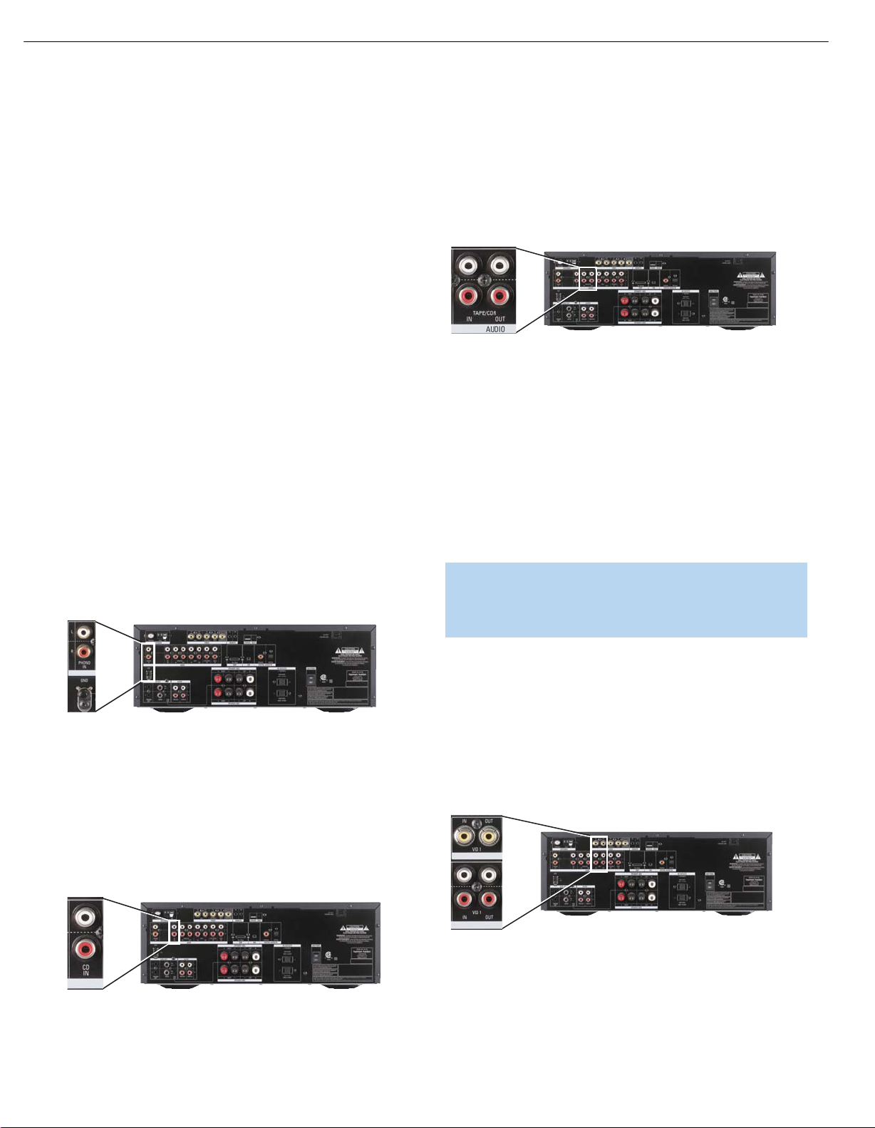
Phono (Turntable)
Connect the audio outputs of your turntable or tonearm with a movingmagnet (MM-type) cartridge to the Phono Inputs, and connect the
ground wire to the Ground Terminal immediately below the Phono Inputs
(not the AM Antenna Ground Terminal). If the cartridge is a moving-coil
(MC-type) cartridge, it requires a separate phono preamp (available at
your local electronics store) before you connect it to the Phono Inputs.
See Figure 14.
Tape
The Tape source is used for audio recorders, such as a CDR, MiniDisc
or cassette deck.
Connect the output jacks on your recorder to the Tape/CDR Audio
Input jacks on the HK 3490, and the input jacks on your recorder to
the Tape/CDR Output jacks on the HK 3490. See Figure 16.
Figure 16 – Tape/CDR Audio Inputs and Outputs
To listen to the Tape/CDR source, press the Tape Mon Button. The upper
line of the Message Display will indicate the last-selected source, which is
always available at the Tape/CDR Outputs for recording. The T-Mon message
will flash in the lower line, indicating that the HK 3490 is playing the signal
present at the Tape/CDR inputs. When the recorder is in Playback-Only
mode, this signal will originate in the recorder, e.g., when playing a
commercial CD. If the recorder is in recording mode and has off-head
playback capability, you may monitor recording of the source displayed
in the upper line. If the recorder does not have off-head playback, you will
not be able to monitor the recording. To hear the original source, press the
Tape Mon Button to stop monitoring the recording.
NOTE: To make recordings, insert blank media in the recording
device and set it in Recording mode. The fact that a signal
is always available at the Tape/CDR Outputs doesn’t mean
recording is taking place if the recorder is not set to record.
HK 3490
Figure 14 – Phono Inputs and Ground
If your turntable has an MM-type cartridge and a built-in phono preamp,
do not
connect it to the Phono Inputs. Use one of the other available
audio input sources on the HK 3490.
Compact Disc (CD) Player
Connect the analog audio outputs of your CD player (or another audioonly device) to the CD Audio Inputs. See Figure 15.
HK 3490
Figure 15 – CD Audio Inputs
19
Video 1 Source
Since this source includes audio and video recording output jacks, it is
best suited to a video recorder, such as your VCR or DVR, even though
the remote codes are programmed to operate the DMC 1000. Simply
use your video recorder’s original remote.
Connect your recorder to the Video 1 Audio Inputs and Outputs. Then
connect the recorder to the Video 1 Composite Video Input and Output.
See Figure 17.
HK 3490
Figure 17 – Video 1 A/ V Inputs and Outputs
Remember to connect the audio and video
Input
recorder to the Video 1
input
and video
jacks on your recorder to the Video 1
jacks on the HK 3490, and the audio
on the HK 3490.
output
jacks on your
Output
jacks
19
Page 18
HK 3490
Top Leaders
HK 3490
18
HK3490 harman/kardon
INSTALLATION
Video 2 Source
The Video 2 source is used only for playback. Since the remote is
preprogrammed to operate a Harman Kardon DVD player when the
Video 2 source is selected, we recommend that you connect a DVD
player to the Video 2 Inputs.
You may have observed that the HK 3490 does not feature surround
sound decoding, other than Dolby Virtual Speaker. If you prefer the
complete home theater experience, you may wish to consider
purchasing a full-featured Harman Kardon AVR Series audio/video
receiver. However, we hope you will find that using a DVD player with
the HK 3490 in smaller settings, such as a bedroom or den, surpasses
the audio performance of most televisions, including those with onboard
stereo speakers.
Connect the left and right analog audio outputs of the DVD player to
the Video 2 Audio Inputs on the HK 3490. Then connect the composite
video output of the DVD player, usually colored yellow, to the Video 2
Video Input. See Figure 18.
Figure 19 – Front- and Rear-Panel Video 3 A/ V Inputs
To connect an iPod to the Video 3 Inputs, insert the 1/8" mini plug on
the A/ V cable included with the HK 3490 into the headphone jack of
the iPod. Insert the left and right analog audio plugs on the other end of
the A/ V cable into the Video 3 Audio Inputs on the front of the receiver.
If the iPod is capable of playing videos or displaying images, insert the
composite video plug of the A/ V cable into the Video 3 Video Input.
HK 3490
Figure 18 – Video 2 Audio and Video Inputs
NOTE: If you receive your television programming using your
TV with an antenna or direct cable connection, connect the TV’s
analog audio outputs (if available) to the Video 2 Analog Audio
Inputs. Do not connect any video output on the television set to
any Video Input on the receiver. See Step Five for information on
connecting the receiver’s Video Monitor Outputs to the television.
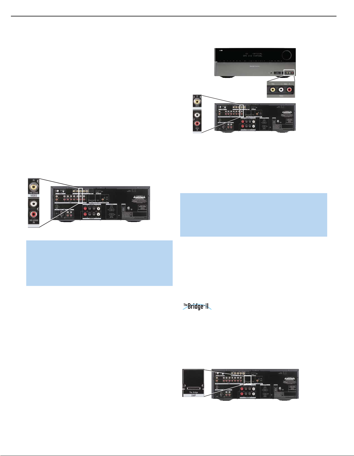
Video 3 Source
The Video 3 source is used only for playback.The Video 3 source has
two sets of input jacks, one located on the HK 3490’s rear panel and
one set on the front panel. If you wish to connect a video device more
or less permanently, you may prefer to connect it to the rear-panel
inputs for a neater appearance. You may prefer to reserve the frontpanel inputs for devices connected on a temporary basis, such as an
iPod (not included), a camcorder, a game console, or another type of
media player with analog audio and/or video outputs.
You may connect devices to both the front- and rear-panel inputs
simultaneously. To select either device, press the Video 3 Source Selector
on the HK 3490’s front panel or remote repeatedly. When VIDEO 3
appears on the front panel of the HK 3490, the rear-panel inputs are
active. When VIDEO F appears, the front-panel inputs are active.
Connect the left and right analog audio outputs of your device to the
corresponding Video 3 Inputs on either the front or rear panel, and
if available, connect the composite video output of the device to the
Video 3 Video Input on the same panel. See Figure 19.
NOTE: The iPod classic, iPod touch and iPhone require a special
cable (not included) for video playback through the HK 3490.
The cable features a dock receptacle at one end, and conventional
A/V plugs at the other end that may be connected to the
HK 3490 as described above. Visit www.apple.com for more
information about the cable.
When the front-panel inputs and tone controls are not in use, place the
supplied covers over them for a cleaner appearance by snapping the
covers in place. To remove the covers, gently press on the left side of
each cover so that it pivots out.
Since the remote is preprogrammed to operate a Harman Kardon DVD
player when the Video 3 source has been selected, use the source
device’s original remote to control other components, or operate an
iPod using its own controls.
Docking Station
With the optional The Bridge II docking station, you can listen to audio
or view videos stored on your iPod, iPod touch or iPhone (not included),
use your HK 3490 remote control to operate the iPod, and even charge
the iPod while it’s docked in The Bridge II docking station. Simply plug
the proprietary cable from The Bridge II unit into the special connector
on the rear of the HK 3490. See Figure 20. Refer to the owner’s
manual for The Bridge II model for more information.
Figure 20 – The Bridge II Connection
Page 19
HK 3490
HK 3490
HK 3490
HK 3490
19
HK3490 harman/kardon
INSTALLATION
Step Five – Connect the Video Display
Only video connections should be made between the receiver and
your video display (TV), unless your TV is the source for your television
programming (see note below Figure 18).
To view video or images played by your source devices, connect the
Video Monitor Output of the HK 3490 to a Composite Video Input on
your television or video display. See Figure 21. Consult the manual for
your TV so that you understand how to select the correct video input.
Figure 21 – Video Monitor Output
Step Six – Connect the Remote IR Input and
Output (Optional)
The HK 3490 is equipped with a Remote IR Input and a Remote IR
Output to facilitate use of your system with a remote control in a variety
of situations.
When the HK 3490 is placed in such a way that aiming the remote at
the front-panel IR sensor is difficult, such as inside a cabinet or facing
away from the listener, you may connect an external IR receiver, such
as the optional Harman Kardon HE 1000, to the Remote IR Input jack.
Step Seven – Connect Optional External
Equipment
If you wish to use the HK 3490 with an external power amplifier,
remove the jumpers connecting the Preamp Outputs and Main-Amp
Inputs. Store the jumpers in a safe place in case they are needed in the
future. Connect the left and right Preamp Outputs of the HK 3490 to
the analog audio inputs on the external power amplifier. See Figure 23.
Figure 23 – Preamp Outputs and Main-Amp Inputs
You may adjust the Volume and Tone Controls using the HK 3490’s
front panel or remote (volume only).
If you wish to install an external processor, such as an equalizer, connect
it to the Preamp Outputs and Main-Amp Inputs. Remove the jumpers
and store them in a safe place. Connect the HK 3490’s Preamp Outputs
to the processor’s analog audio inputs, and then connect the processor’s
analog audio outputs to the Main-Amp Inputs on the HK 3490.
Alternatively, you may connect the external processor to the HK 3490’s
Tape Monitor Loop. See Figure 16.
Step Eight – Plug In AC Power
If any of your source devices are equipped with a compatible Remote IR
Input, use a 1/8" mini-plug interconnect cable (not included) to connect
the HK 3490’s Remote IR Output to the source device’s Remote IR
Input, which will pass any applicable remote signals transmitted through
the HK 3490 to the source device. This enables you to control your
sources even when the HK 3490 itself is controlled via an external
IR receiver.
To control more than one source device using the Remote IR Output,
connect all sources in “daisy chain” fashion, with the HK 3490’s Remote
IR Output connected to the first device’s Remote IR Input, that device’s
Remote IR Output connected to the next device’s Remote IR Input, and
so forth. See Figure 22.
Figure 22 – Remote IR Input and Output
NOTE: Not all remote-controllable devices are equipped with
compatible IR inputs and outputs. Check with the manufacturer
of the source device for more information on the type of IR
signal expected. The HK 3490 will output a “stripped carrier”
IR signal.
Having made all of your wiring connections, it is now time to plug each
component’s AC power cord into a working outlet.
You may plug two devices into the AC Switched Accessory Outlets on
the rear of the HK 3490. See Figure 24. Make sure each device draws
no more than 100 watts. The devices should have their mechanical or
master power switches turned on, and they will power on any time the
HK 3490 is turned on.
Figure 24 – AC Switched Accessory Outlets
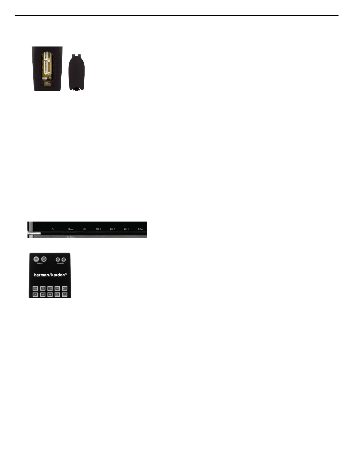
Step Nine – Insert Batteries in Remote
The HK 3490 remote control uses four AAA batteries, which are included.
To remove the battery cover located on the back of the remote,
squeeze the tab and lift the cover.
Insert the batteries as shown in the diagram, making sure to observe
the correct polarity. See Figure 25.
21
Page 20
20
HK3490 harman/kardon
INSTALLATION
Figure 25 – Remote Battery Compartment
When using the remote, point the lens toward the front panel of
the HK 3490. Make sure no objects, such as furniture, are blocking
the remote’s path to the receiver. Bright lights, fluorescent lights and
plasma video displays may interfere with the remote’s functioning.
The remote has a range of about 20 feet, depending on the lighting
conditions. It may be used at an angle of up to 30 degrees to either
side of the HK 3490.
If the remote seems to operate intermittently, then make sure the batteries
have been inserted correctly, or replace the batteries with fresh ones.
Step Ten – Turn On the HK 3490
Place the HK 3490 in Standby mode by turning on the Main Power Switch
on the rear panel. The Power Indicator will turn amber. The HK 3490 may
be turned on from Standby mode by pressing the Power Switch or any
Source Selector on either the front panel or the remote. See Figures 26
and 27.
Figure 26 – Front-Panel Power Switch
Figure 27 – Remote Control Power Switch
22
22
Page 21
21
HK3490 harman/kardon
OPERATION
Now that you have installed your system components, you are ready
to begin enjoying your new audio system.
Turning On the HK 3490
After you plug the power cord into an AC outlet and turn on the Main Power
Switch on the rear panel, the Power Indicator should light up in amber. This
indicates that the HK 3490 is in Standby mode and is ready to be turned
on. See Figure 26.
The HK 3490 may be turned on by pressing the Power Switch or any
Source Selector on the front panel or the remote. See Figures 26 and 27.
The Power Indicator will turn white to indicate that the HK 3490 is on.
If the PROTECT message appears in the Message Display, unplug the
receiver from AC power and check all of your wires and connections.
Make sure no speaker wires are shorting out by touching each other,
and that there are no breaks in the insulation covering any of the speaker
wires, interconnects or the power cord. If the PROTECT message still
appears when you plug in the HK 3490 and try to turn it on again,
bring the receiver to an authorized Harman Kardon service center for
assistance.
To turn the receiver off, press the Power Switch on the front panel,
or press the Power Off Button on the remote. When the HK 3490 is
left unplugged, any settings you have programmed, including system
configuration and preset radio stations, will be preserved indefinitely.
Volume Control
The volume may be adjusted either by turning the knob on the front
panel (clockwise to increase volume or counterclockwise to decrease
volume), or by pressing the Volume Control Buttons on the remote. See
Figure 28. The volume is displayed as a negative number of decibels
(dB) below the 0dB reference point. Unlike some volume controls on
other products, 0dB is the maximum volume for the HK 3490. Although
it’s physically possible to turn the volume to a higher level, doing so may
damage your hearing and your speakers. For certain more-dynamic
audio materials, even 0dB may be too high, allowing for damage to
equipment.
in use and the Subwoofer Link Switch is on, muting will turn off the
subwoofer’s amplifier to conserve energy. The MUTE message will flash
in the display as a reminder. To restore normal audio, either press the
Mute Button again, or adjust the volume. Turning off the HK 3490 will
also end muting.
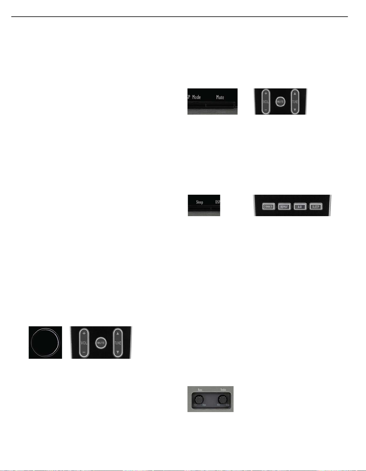
Figure 29 – Mute Buttons
Sleep Timer
You may program the HK 3490 to play for up to 90 minutes and then
turn off automatically using the sleep timer.
Press the Sleep Button on the front panel or remote, and the time until
turn-off will be displayed. Each additional press of the Sleep Button will
reduce the time until turn-off by 10 minutes, until the OFF setting is
reached, which disables the sleep timer. See Figures 30 and 31.
Figure 30 – Front-Panel Sleep Button Figure 31 – Remote Control Sleep Button
When the sleep timer has been set, the front-panel display will
automatically dim to half-brightness. If you press any button on the
remote or front panel, the display will return to full-brightness. The
display will dim again several seconds after your last command.
If you press the Sleep Button after the timer has been set, the remaining
time until turn-off will be displayed. You may press the Sleep Button to
change the time until turn-off. Pressing and holding the Sleep Button will
disable the sleep timer, and the SLEEP OFF message will appear.
Tone Controls
You may boost or cut either the treble or the bass frequencies by up
to 10dB.
Figure 28 – Volume Controls
The HK 3490 is designed to reproduce audio with a minimum amount
of distortion. This clarity may lead you to believe that your hearing and
the equipment can handle higher volumes. We urge caution with regard
to volume levels.
Mute Function
To temporarily mute all speakers and the headphones, press the Mute
Button on the front panel or remote. See Figure 29. Any recording in
progress will not be affected. If the Subwoofer Trigger Outputs are
The Bass and Treble Tone Controls may be adjusted using the knobs on
the front panel. Remove the front-panel covers if necessary, then gently
press the desired control knob until it unlatches and pops out. Turn the
appropriate knob counterclockwise to reduce the levels of the low
frequencies (Bass Control) or the high frequencies (Treble Control), and
turn it clockwise to increase the levels for the low or high frequencies.
See Figure 32.
Figure 32 – Tone Controls
You may also adjust the balance to compensate for speaker placement
or the acoustic characteristics of your listening room. Ideally, the audio
23
Page 22
22
HK3490 harman/kardon
OPERATION
should be heard most clearly at a point exactly midway between the left
and right speakers, unless the artist has mixed the recording in a way
that pans sounds to one side or the other. If your speakers are not
placed the same distance from the listening position, or if your room has
other unusual characteristics, gently press the Balance Control knob until
it unlatches and pops out. Then turn it counterclockwise to move the
sound toward the left speaker or clockwise to move the sound toward
the right speaker. See Figure 33.
Figure 33 – Balance Control
The Balance Control reduces the level of the speaker opposite the
pointer. For example, turning the knob from the midpoint toward “R”
reduces the level of the left speaker, leaving the right speaker unaffected.
If two pairs of speakers are connected to the HK 3490, then both will
be affected.
IMPORTANT NOTE: Do not attempt to install the front-panel
covers with the Tone and Balance Control knobs in the unlatched
position. Gently press each knob until it latches. When locked,
the controls cannot be adjusted, preventing inadvertent changes
to your desired settings.
Headphones
Plug the 1/4" plug on a pair of headphones into the headphone jack on
the front of the receiver for private listening. See Figure 34.
Figure 34 – Headphone Jack
Speaker 1/2
The HK 3490 may be used with up to two pairs of speakers for
additional sound power in the main listening room or if you wish to
place the second pair of speakers in another room, or even outdoors
(when you select weather-resistant loudspeakers). Select each pair of
speakers by pressing its associated button on either the front panel or
remote. See Figure 35.
Figure 35 – Speaker 1/2 Buttons
Press the button a second time to deactivate that pair of speakers. You
may activate both speaker pairs simultaneously, or deactivate both pairs
for private listening through the headphones. When either of the speaker
pairs are deactivated, if the corresponding Subwoofer Trigger Output is
connected to the subwoofer and the corresponding Subwoofer Link
Switch is on, the trigger signal will be deactivated, turning off the
subwoofer amplifier and conserving energy when the subwoofer is
not needed.
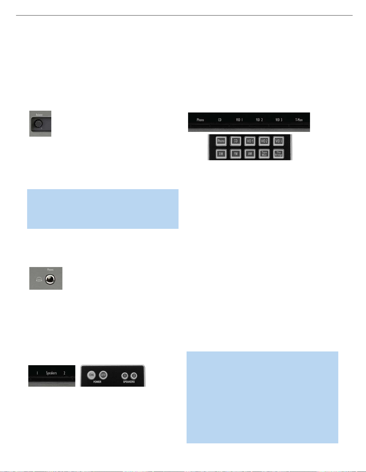
Source Selection
Select a source device connected to the HK 3490 for playback by
pressing its associated button on the front panel or remote control.
See Figure 36.
Figure 36 – Source Selectors
To enjoy video sources, make sure to connect the device’s composite
video output to the correct Video Input on the HK 3490. In addition,
connect the HK 3490’s Video Monitor Output to an input on your
television or video display.
To select whether the source will use its analog audio input or one of
the digital audio inputs, press and hold the front-panel Source Selector
and simultaneously tap the front-panel T-Mon Button repeatedly until the
desired input appears in the Message Display. Audio input selection
requires use of the front-panel controls and cannot be selected using
the remote control.
To select a device connected to either the front- or rear-panel Video 3
Inputs, press the front-panel or remote Video 3 Source Selector
repeatedly to toggle between the front- and rear-panel Video 3 Inputs,
as indicated in the front-panel display. When the front-panel inputs are
not in use, you may snap the supplied cover over them. Remove the
cover by pressing on the left side until it pivots outward.
If you have connected a three-head tape deck to the Tape/CDR Inputs,
you may monitor a recording while it is being made so that you can
confirm that the correct program material is being recorded and make any
necessary adjustments to the recording level. Press the T-Mon Button on
the front panel to hear playback from the tape deck’s playback head.
When the recording is being monitored, the T-MON message will flash.
Press the T-Mon Button again to hear the original source.
NOTES:
• The HK 3490 is not an audio/video surround sound receiver.
It is only capable of playing source programs in one- or twochannel formats, and any information encoded in additional
channels will be lost. The HK 3490 cannot decode digital
surround-sound programs. If you have connected the analog
audio and composite video outputs of a DVD player to the
HK 3490, remember to select two-channel audio in the DVD
player and disc menus. However, you may press the DSP
Surround Button to select a Dolby Virtual Surround mode
(Reference or Wide) to expand the presentation of the sound
field even though only two main loudspeakers are in use.
Page 23
23
HK3490 harman/kardon
OPERATION
• The HK 3490 does not switch the last-selected video source
when an audio-only source, such as Phono, CD or Tape/CDR,
is selected subsequently. It is not possible to view video while
listening to an audio-only source.
Using the Tuner (AM, FM and XM Modes)
The HK 3490’s built-in tuner may be selected in one of two ways
(see Figure 37):
1. Press the front-panel AM or FM Button. The front-panel FM Button
toggles between the FM and XM bands.
2. Press the AM, FM or XM Button on the remote.
Figure 38 – Tuning a Station
When an FM station has been tuned, pressing the FM Mode Button will
switch between stereo and mono tuning, which may improve reception
of weaker stations. See Figure 39.
Figure 37 – Tuner Input Selection
Radio stations may be selected in one of five ways (see Figures 38– 40):
1. If you know the frequency number, enter it directly by first pressing
the Direct Button on the remote, and then using the Numeric Keys. It
is not necessary to press the Direct Button when XM Radio is in use.
2. After you have programmed preset stations (see below), either enter
the preset number (1 through 30) using the remote or use the frontpanel Preset Stations Button to scroll through the list of presets.
When XM Radio is in use, first press the FM Mode Button repeatedly
‹/›
to select Preset Search mode. Then use the
Buttons to select
a lettered bank of presets. To select a numbered preset within a
bank, make sure the HK 3490 is in Preset Search mode, then use
⁄/¤
the Numeric Keys, the
Buttons or the Preset Stations Buttons.
3. In Auto Tuning mode, press and hold the Tuning Buttons (front-panel
or remote) to scan in the chosen direction until a station with
acceptable signal strength is detected.
4. In Manual Tuning mode, with each press of the Tuning Buttons the
HK 3490 will tune the next frequency increment (0.1MHz for FM,
or 10kHz for AM) in the selected direction.
NOTE: When XM Radio is in use, there are no auto or manual
⁄/¤
tuning modes. Use the Tuning Button or
Buttons (only
when in All Channel Search mode) to select a channel. Press
and hold the button to search faster.
Figure 39 – FM Mode Button
To store a station in one of the 30 AM/FM presets (see Figure 40):
1. Tune the desired station.
2. Press the Memory Button on the remote.
3. Use the Numeric Keys to enter the desired preset number.
To clear a station from the preset memory:
1. Tune the preset station using any of the methods described above.
2. Press the Memory Button.
3. Within five seconds, press the Clear Button.
5. Press the Preset Scan Button on the front panel or remote to scan
through the previously programmed preset stations. The tuner will
pause for five seconds at each frequency before tuning to the next
preset. Press the Preset Scan Button again to select the current
station and stop scanning. When XM Radio is in use, this button is
used to change the display as follows: channel name and number,
category, artist and song title.
Figure 40 – Programming Presets
When XM Radio is in use, programming presets is somewhat different.
1. Tune to the desired channel.
2. Press the Memory Button on the remote.
3. Use the ‹/›Buttons to select the desired preset bank (A through E).
4. Use the
⁄/¤
Buttons to select a numbered location (1 through 8).
25
Page 24
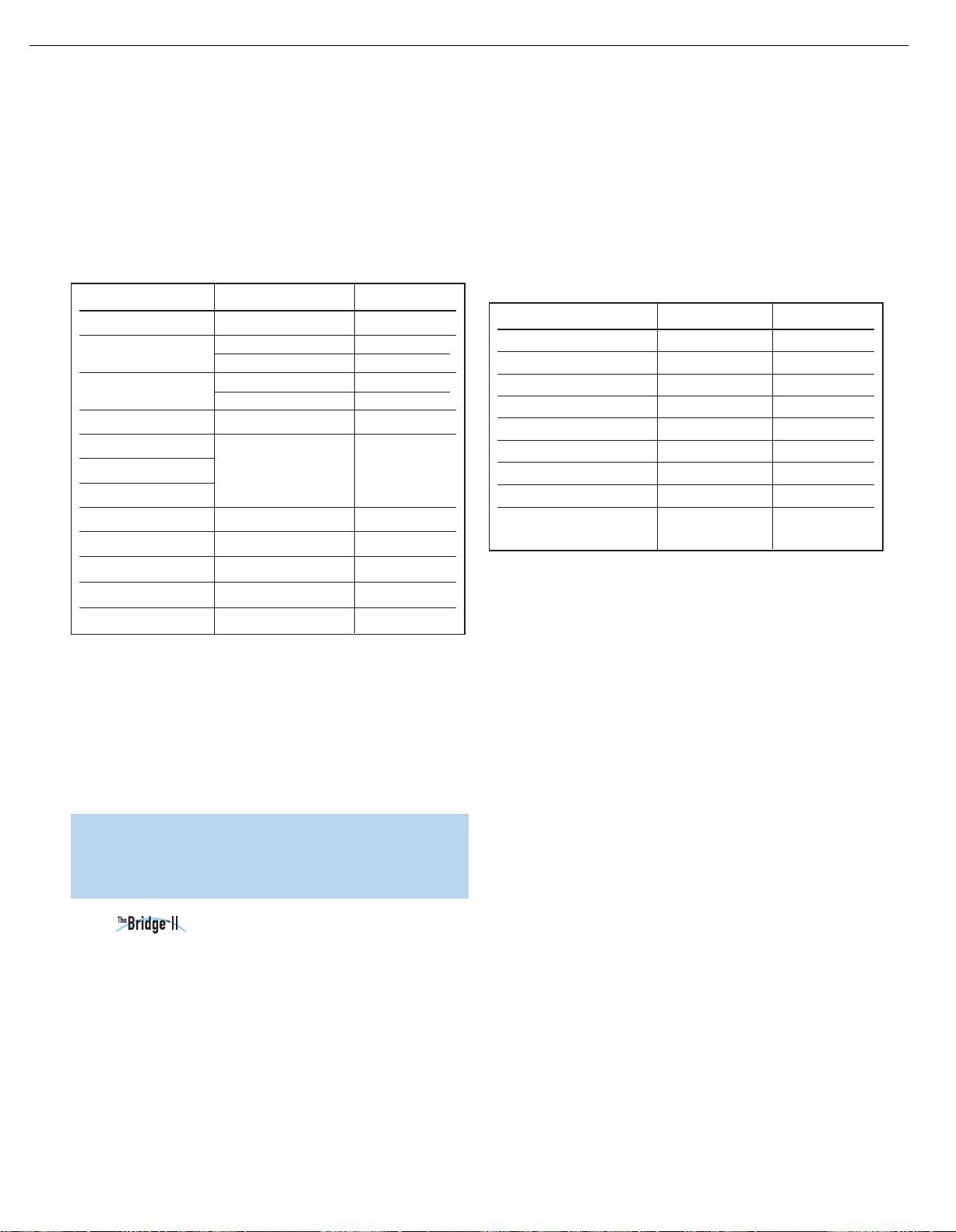
24
HK3490 harman/kardon
OPERATION
5. Press the Memory Button on the remote to complete the process
and let the HK 3490 return to normal operation.
To delete an XM Radio preset, tune to the preset station and press the
Clear Button. To delete all XM Radio presets in all banks, press and hold
the Clear Button until the ALL DELETED message appears. Table 2 may
be helpful to you as a reference while using the XM Radio tuner.
Table 2 – Using the XM Radio Tuner
XM Radio Function Remote Control Key Front-Panel Button
Toggle Search Modes FM Mode FM Mode
Scroll Preset Numbers (1–8)
Channel Search
Display Mode Preset Scan Preset Scan
Exit All Channel Search
Changes Category
Changes Preset Group
Enter/OK OK N/A
Preset Memory Mode Memory N/A
Clear Preset Memory Mode Clear N/A
Clear All Preset Memories Press and Hold Clear N/A
Enter Numeric Numbers 0–9 Numeric Keys N/A
Preset Up/Up Arrow (⁄) Preset Up
‹/›
(¤)
Preset Down
) N/A
Preset Down/Down Arrow
Tuning Up Tuning Up
Tuning Down Tuning Down
Left/Right Arrow (
Auto Preset (FM Only)
You may automatically program all FM radio stations in your area that
are received with acceptable signal strength into the HK 3490’s presets.
Press and hold the Auto Preset Button until the Memory and Preset
Indicators flash in the front-panel display. The tuner will automatically
scan through the entire FM band, entering all stations with acceptable
signal strength into the presets until either all 30 presets have been
filled, or the tuner has scanned the band twice.
In normal operation, information from the iPod will appear in the HK 3490’s
Message Display. While a track is playing, its title will scroll once on the
upper line, and the elapsed and remaining track times will appear on the
lower line. While navigating the iPod, the menu title or current setting will
appear on the upper line, and the current menu line or setting option will
appear on the lower line.
Table 3 summarizes the controls available when The Bridge II unit is in use.
Table 3 – Using The Bridge II
iPod Function Remote Control Key Front Panel-Button
Play Play (›) Preset Scan
Pause Pause ( || ) Preset Scan
Menu Menu FM Mode
Select OK Preset Scan
Scroll Reverse Up Arrow (⁄) Preset Up
Scroll Forward Down Arrow (¤) Preset Down
››
Forward Search/Next Track Right Arrow (
Reverse Search/Previous Track Left Arrow (
Switch between normal operation Press and hold Menu Press and hold
and iPod Manual mode FM Mode Button
) Tuning Up
l
‹‹
) Tuning Down
l
When the HK 3490 is in Standby mode, the iPod is not charged.
It is not possible to view videos or still images stored on the iPod.
To access the full functions of the iPod, press and hold the Menu Button
(FM Mode Button on front panel) to switch it to Manual mode. You may
navigate the iPod using the HK 3490 remote while viewing its menus on
the iPod screen. Manual mode allows access to functions such as Repeat
and Shuffle. Although the audio portion of video content may be played,
it will not be possible to view the content on a video display connected
to the HK 3490. To return to normal operation, press and hold the Menu
Button again until the check mark appears on the screen of the iPod.
Recording
NOTE: If there are a large number of FM stations in your area,
Auto Preset will overwrite any presets you programmed previously.
Stations with exceptionally strong signals may be programmed
into more than one preset.
Using Docking Station
The Bridge II docking station is an optional unit that may be used with a
compatible iPod, iPod touch or iPhone (not included). When The Bridge II
docking station is connected to its proprietary input on the HK 3490
and the iPod is docked, you may play the audio materials on your iPod
through your high-quality audio system, operate the iPod using the HK 3490
remote or the HK 3490’s front-panel controls, and charge the iPod.
Either press the front-panel Phono Selector repeatedly until the
DMP/THE BRIDGE IS CONNECTED message scrolls across the front
panel, or press The Bridge Button on the remote to select The Bridge II
docking station as the input source.
26
Two-channel analog audio signals, as well as composite video signals,
are normally available at the appropriate recording outputs. Thus, to
make a recording, you need only make sure to connect your audio
or video recorder to the appropriate output jacks, as described in the
Installation section, insert blank media and make sure the recorder is
turned on and recording while the source is playing.
You may monitor your recording if your recorder has separate record
and playback heads. Press the front-panel T-Mon Button to monitor the
recording using the playback head, indicated by the T-MON message
flashing. This will not affect the recording being made from the original
source. To hear the original source again, press the T-Mon Button again.
If your recorder does not have off-head playback, then you will not hear
anything when you press the T-Mon Button, unless the recorder is being
used for playback.
Page 25

25
HK3490 harman/kardon
OPERATION
NOTE: Please make certain that you are aware of any copyright
restrictions on any material you record. Unauthorized duplication
of copyrighted materials is prohibited by federal law.
Dim Function
Some people find the front-panel messages distracting and would prefer
to dim them or turn them off altogether.
To dim the display, press the Dim Button on the front panel or remote.
Each button press will cycle through the three settings of:
VFD FULL: Normal brightness
VFD HALF: Display is dimmed but still visible; the light inside the
volume knob goes dark
VFD OFF: Display goes completely dark except for Power Indicator
to remind you that the receiver is turned on
NOTE: When the remote is in the device mode for either the
Video 1 or Video 2 source, the Dimmer Button on the remote
will only affect the source device (if compatible), and will not
affect the HK 3490.
Processor Reset
If you wish to fully reset the HK 3490 to its factory defaults, or if it
behaves erratically after a power surge, first turn the Master Power
Switch off and unplug the AC power cord for at least three minutes.
Plug the cord back in and turn the receiver back on. If this doesn’t
help, you may want to try a system reset.
NOTE: A system reset erases all user configurations, including tuner
presets. After a reset, you will need to reenter all of these settings.
Place the receiver in Standby mode by pressing the Power Switch so
that the Power Indicator turns amber. Simultaneously press and hold the
front-panel Preset Scan and Mute Buttons for at least five seconds until
the software version number, followed by the RESET message, appears
in the display.
The unit will return to Standby mode, and you may power it on.
You may reset the HK 3490 by using a sharp object to press the rearpanel Reset Button. This method does not erase user configurations.
If the receiver still does not function correctly after a processor reset,
contact an authorized Harman Kardon service center for assistance.
Service centers may be located by visiting www.harmankardon.com.
Memory
If the HK 3490 is unplugged or experiences a power outage, it will
retain user settings indefinitely.
Page 26

26
HK3490 harman/kardon
TROUBLESHOOTING GUIDE
SYMPTOM CAUSE SOLUTION
Unit does not function when Main • No AC power • Make certain AC power cord is plugged into
Power Switch is pushed a live outlet
• Check to see whether outlet is switch-controlled
Display lights, but there’s no • Intermittent input connections • Make certain that all input and speaker connections
sound or picture are secure
• Mute is on • Press Mute Button
• Volume Control is down • Turn up Volume Control
• Desired source not selected • Press correct Source Selector
• Speakers deactivated • Press Speaker 1 or Speaker 2 Button
• Headphones are in use • Unplug headphones
• Jumper pins between Preamp Outputs • Replace jumper pins or, if external amplifier
and Main-Amp Inputs were removed is in use, make sure it is turned on
No sound from any speaker; • Amplifier is in Protection mode • Check speaker-wire connections for shorts at receiver and
light around Power Switch is red due to possible short speaker ends
• Amplifier is in Protection mode • Contact your local Harman Kardon service center
due to internal problems
Unit does not respond to • Weak batteries in remote • Change remote batteries
remote commands • Remote sensor is obscured • Make certain front-panel sensor is visible to remote
or connect an optional remote sensor
Intermittent buzzing in tuner • Local interference • Move unit or antenna away from computers, fluorescent
lights, motors or other electrical appliances
Audio sources sound distorted • CD player or other audio device • Only plug a device into the Phono Inputs if it is a
incorrectly plugged into Phono Inputs turntable with a moving-magnet cartridge, or if it is a
turntable with a moving-coil cartridge with a phono preamp
• Turntable not plugged into Phono Inputs • Do not use a turntable with any inputs other than the Phono
Inputs, unless it has a moving-magnet-type cartridge and
includes a phono preamp
No video image • Source device’s video output not • Connect the source’s composite video output to
connected to HK 3490 the correct video input on the HK 3490
• Wrong source selected • Press the correct Source Selector on the HK 3490
• Video Monitor Output not connected • Connect the HK 3490’s Video Monitor Output to a composite
to display video input on your television or video display
• Wrong video input on video • Consult the manual for your television for instructions on
display selected selecting the correct video input
• Audio-only source selected • It is not possible to view video while listening to the
Phono, Tape/CDR or CD sources or to the tuner
In addition to the items shown above, additional information on troubleshooting possible problems with your HK 3490, or on installation-related issues,
may be found in the list of “Frequently Asked Questions,” which is located in the Product Support section at www.harmankardon.com.
Processor Reset
If you wish to fully reset the HK 3490 to its factory defaults, or if it behaves erratically after a power surge, first turn the
Master Power Switch off and unplug the AC power cord for at least three minutes. Plug the cord back in and turn the
receiver back on. If this doesn’t help, you may want to try a system reset.
NOTE: A system reset erases all user configuratio ns, including tuner presets. After a reset, you will need to reenter all of
these settings.
Place the receiver in Standby mode by pressing the Power Switch so that the Power Indicator turns amber. Simultaneously
press and hold the front-panel Preset Scan and Mute Buttons for at least five seconds until the software version number,
followed by the RESET message, appear in the display. The unit will return to Standby mode, and you may power it on.
Memory
28
If the HK 3490 is unplugged or experiences a power outage, it will retain user settings indefinitely.
Page 27
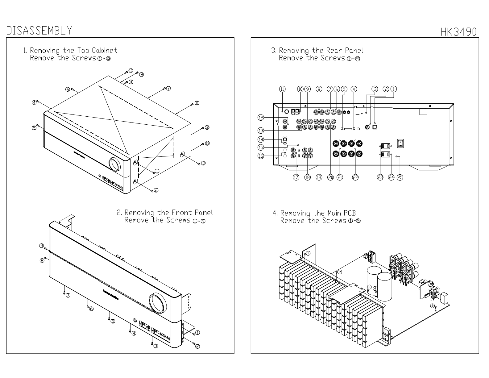
27
HK3490 harman/kardon
Page 28

28
HK3490 harman/kardon
HK3490 DISASSEMBLY PROCEDURE
1 TOP-CABINET (21) REMOVAL
1. Remove 13 screws (S1) and then remove the Top-cabinet.
2 FRONT PANEL ASS’Y REMOVAL
1. Remove the Top-cabinet, referring to the previous step 1.
2. Disconnect the lead wire (BN22-11P) on the Potentiometer PCB (43-4) from connector (CN22) on
the Input PCB (45).
3. Disconnect the lead wire (BN13-9P) on the Front PCB (43-1) from connector (CN13) on the Main
PCB (44-1).
4. Disconnect the connector (CN87-19P) on the Front PCB (43-1) from connector (CN87) on the Main
PCB (44-1).
5. Disconnect the lead wire (BN73-5P) on the Phone PCB (43-3) from connector (CN73) on the Main
PCB (44-1).
6. Disconnect the lead wire (BN84-5P) on the Front input video PCB (43-6) from connector (CN84) on
the Input PCB (45).
7. Remove 1 screw (S6) and then lead wire (JW98,JW99-1P) on the PCB (43-5, 43-3).
8. Remove 1 screw (S6) and then lead wire (JW97-1P) on the Power LED PCB (43-2).
9. Remove 10 screws (S1) and then remove the Front Panel ASS’Y.
3 POTENTIOMETER PCB (43-4) REMOVAL
1. Remove the Top-cabinet, referring to the previous step 1.
2. Remove the Front Panel ASS’Y, referring to the previous step 2.
3. Remove 2 screws (S3) and then remove the Potentiometer PCB (43-4).
4 PHONE PCB (43-3) REMOVAL
1. Remove the Top-cabinet, referring to the previous step 1.
2. Remove the Front Panel ASS’Y, referring to the previous step 2.
3. Remove 2 screws (S4) and then remove the Phone PCB (43-3).
4. Disconnect the lead wire (BN73-5P) from connector (CN73) on the PHONE PCB (43-3).
5 Volume PCB (43-5) REMOVAL
1. Remove the Top-cabinet, referring to the previous step 1.
2. Remove the Front Panel ASS’Y, referring to the previous step 2.
3. Pull out the Volume Knob ASS’Y .
4. Remove 4 screws (S3) and then Volume PCB (43-5).
5. Disconnect the lead wire (BN81-5P) from connector (CN81) on the Volume PCB (43-5).
6 POWER LED PCB (43-2) REMOVAL
1. Remove the Top-cabinet, referring to the previous step 1.
2. Remove the Front Panel ASS’Y, referring to the previous step 2.
3. Remove 2 screws (S3) and then remove the Power LED PCB (43-2).
4. Disconnect the lead wire (BN82-5P) from connector (CN82) on the Power LED PCB (43-2).
7 FRONT INPUT VIDEO PCB (43-6) REMOVAL
1. Remove the Top-cabinet, referring to the previous step 1.
2. Remove the Front Panel ASS’Y, referring to the previous step 2.
3. Remove 2 screws (S3) and then remove the Front input video PCB (43-6).
8 FRONT PCB (43-1) REMOVAL
1. Remove the Top-cabinet, referring to the previous step 1.
2. Remove the Front Panel ASS’Y, referring to the previous step 2.
3. Remove the Potentiometer PCB (43-4) , referring to the previous step 3.
4. Remove the PHONE PCB (43-3), referring to the previous step4.
Page 29

29
HK3490 harman/kardon
5. Remove the Volume PCB (43-5), referring to the previous step 5.
6. Remove the POWER LED PCB (43-2), referring to the previous step 6.
7. Remove the Front input video PCB (43-6), referring to the previous step 7.
8. Remove 12 screws (S3) and then remove the Front PCB (43-1).
9 TUNER MODULE (34) REMOVAL
1. Remove the Top-cabinet, referring to the previous step 1.
2. Disconnect the connector (CON1-Card cable) from connector (CN26) on the Input PCB (45).
3. Remove 2 screws (S5) and then remove the Tuner Module (47).
10 VIDEO PCB (43-8) REMOVAL
1. Remove the Top-cabinet, referring to the previous step 1.
2. Disconnect the connector (CN85-Card cable) from connector (CN85) on the Input PCB (45).
3. Remove 4 screws (S8,S5) and then remove the Video PCB (43).
11 DSP PCB (46-1) REMOVAL
1. Remove the Top-cabinet, referring to the previous step 1.
2. Disconnect the connector (CN51,52,71-Card cable) from connector (CN51,52,71) on Input PCB (45).
3. Disconnect the connector (CN51) from lead wire (BN51-11P) on the Tr PCB (46-2).
4. Remove 5 screws (S8,S5,S14) and then remove the DSP PCB (46-1).
12 INPUT PCB (46-1) REMOVAL
1. Remove the Top-cabinet, referring to the previous step 1.
2. Disconnect the connector (CN21-Card cable) from connector (CN21) on the Main PCB (44-1).
3. Disconnect the connector (CN24) from lead wire (BN24-5P) on the Main PCB (44-1).
4. Remove 7 screws (S5,S14) and then remove the DSP PCB (46-1).
13 POWER TRANS (30) REMOVAL
1. Remove the Top-cabinet, referring to the previous step 1.
2. Disconnect the connector (CN15,CN12) on the Trans PCB (43-7) from lead wire (BN15-3P,BN12-2P)
on the Main PCB (44-1).
3. Disconnect the connector (CN11,CN14,CN15) on the Main PCB (44-1) from lead wire (BN113P,BN14-13P,BN15-3P) on the Trans PCB (43-7)
4. Remove 4 Trans screws (S15) and then remove the Power Trans (42).
14 MAIN PCB ASS’Y(44) REMOVAL
1. Remove the Top-cabinet, referring to the previous step 1.
2. Remove the Power Trans (43-7),referring to the previous step 13.
3. Remove the TUNER MODULE (34), referring to the previous step 9.
4. Remove the VIDEO PCB (43-8), referring to the previous step 10.
5. Remove the DSP PCB (46-1), referring to the previous step 11.
6. Remove the INPUT PCB (46-1), referring to the previous step 12.
7. Disconnect the connector (CN13) from lead wire (BN13-9P) on the Front PCB (43-1).
8. Disconnect the connector (CN73) from lead wire (BN73-5P) on the PHONE PCB (43-3).
9. Disconnect the connector (CN61) from Power cord(35).
10. Remove 15 screws (S5-7EA, S8-2EA,S14-3EA,S9-1EA,S10-1EA,S3-1EA) and then remove the
Main PCB ASS’Y(44).
Page 30
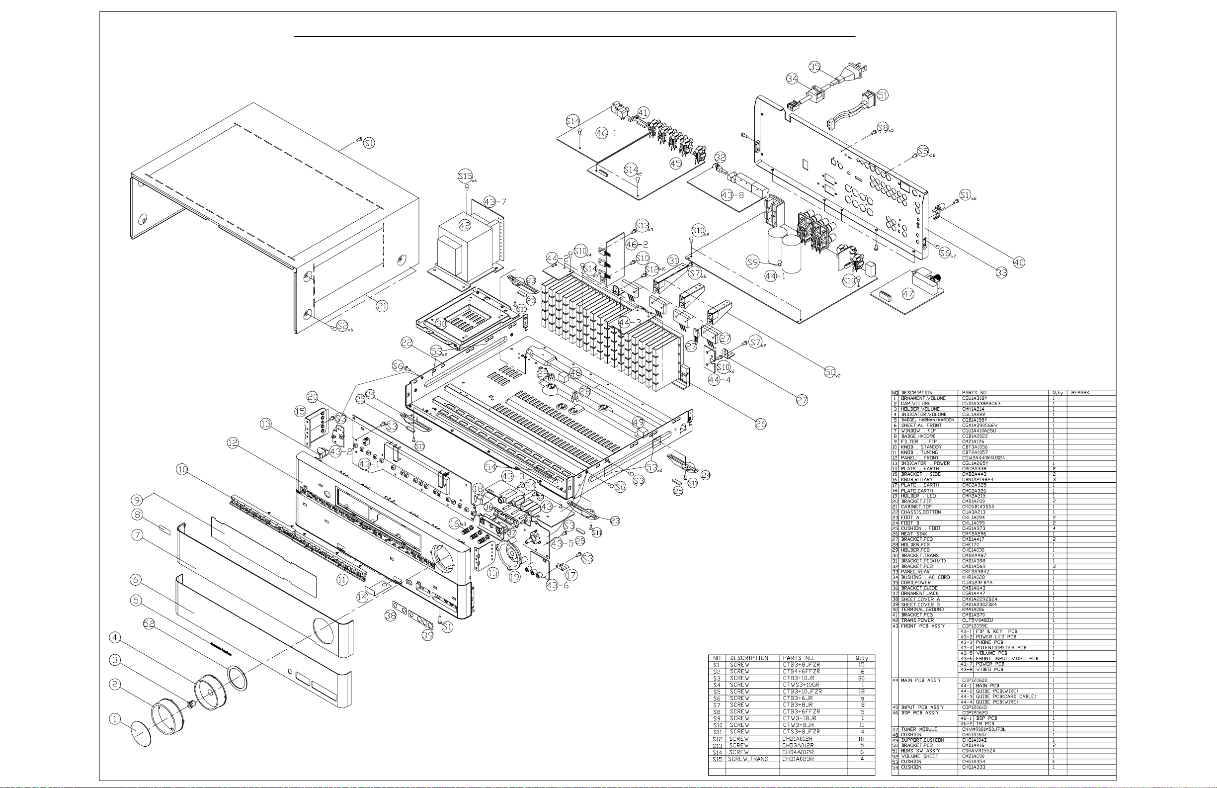
30
HK3490 harman/kardon
LARGER PARTS CHART
NEXT PAGE
Page 31

31
HK3490 harman/kardon
Page 32

32
HK3490 harman/kardon
HK3490/3390 idle current Adjustment
1. Adjust VR31 to set 21.12mV(±5%) on DC EVM.
2. Adjust VR32 as same way above.
Page 33

33
Page 34

34
HK3490 harman/kardon
Page 35

35
HK3490 harman/kardon
Page 36

36
HK3490 harman/kardon
Page 37

37
HK3490 harman/kardon
Page 38

38
HK3490 harman/kardon
Page 39

39
HK3490 harman/kardon
Page 40

40
HK3490 harman/kardon
HK3490 ELECTRICAL PARTS LIST
Ref. Designator Part Number Qty
Description
PCB, FRONT
Capacitors
C802 CCBS1H102KBT CAP , CERAMIC(1000PF/50V) 1000PF 50V 1 EA
C803 CCBS1H102KBT CAP , CERAMIC(1000PF/50V) 1000PF 50V 1 EA
C804 CCBS1H102KBT CAP , CERAMIC(1000PF/50V) 1000PF 50V 1 EA
C806 CCEA1AH471T CAP , ELECT 470UF 10V 1 EA
C807 CCBS1H104ZFT CAP , CERAMIC 0.1UF 50V Z 1 EA
C808 CCBS1H104ZFT CAP , CERAMIC 0.1UF 50V Z 1 EA
C809 CCBS1H223ZFT CAP , CERAMIC(22000PF/50V) 0.022UF 50V 1 EA
C810 CCBS1C222MXT CAP , CERAMIC(2200PF/16V) 2200PF 16V 1 EA
C811 CCBS1H102KBT CAP , CERAMIC(1000PF/50V) 1000PF 50V 1 EA
C812 CCBS1H104ZFT CAP , CERAMIC 0.1UF 50V Z 1 EA
C814 CCEA1AH331T CAP , ELECT 330UF 10V 1 EA
C815 CCBS1H223ZFT CAP , CERAMIC(22000PF/50V) 0.022UF 50V 1 EA
C817 CCBS1H473ZFT CAP , CERAMIC(47000PF/50V) 0.047UF 50V 1 EA
C818 CCEA1CKS100T CAP , ELECT 10UF 16V 1 EA
C819 CCBS1H102KBT CAP , CERAMIC(1000PF/50V) 1000PF 50V 1 EA
C880 CCBS1H101KBT CAP , CERAMIC(100PF/50V) 100PF 50V 1 EA
C881 CCBS1H101KBT CAP , CERAMIC(100PF/50V) 100PF 50V 1 EA
C882 CCBS1H104ZFT CAP , CERAMIC 0.1UF 50V Z 1 EA
C883 CCBS1H104ZFT CAP , CERAMIC 0.1UF 50V Z 1 EA
C900 CCEA1HH100T CAP , ELECT 10UF 50V 1 EA
C901 CCKT1H101KB CAP , CERAMIC 100PF 50V K 1 EA
C902 CCEA1HH100T CAP , ELECT 10UF 50V 1 EA
C903 CCEA1HH100T CAP , ELECT 10UF 50V 1 EA
C904 CCCT1H470JC CAP , CERAMIC 47PF 50V J 1 EA
C905 CCEA1HH470T CAP , ELECT 47UF 50V 1 EA
C906 HCQI1H183JZT CAP , MYLAR 0.018UF 50V J 1 EA
C907 HCQI1H183JZT CAP , MYLAR 0.018UF 50V J 1 EA
C908 HCQI1H332JZT CAP , MYLAR 3300PF 50V J 1 EA
C909 CCEA1HH100T CAP , ELECT 10UF 50V 1 EA
C910 CCKT1H101KB CAP , CERAMIC 100PF 50V K 1 EA
C911 CCEA1HH470T CAP , ELECT 47UF 50V 1 EA
C912 CCCT1H470JC CAP , CERAMIC 47PF 50V J 1 EA
C913 CCEA1HH100T CAP , ELECT 10UF 50V 1 EA
C914 CCEA1HH100T CAP , ELECT 10UF 50V 1 EA
C915 HCQI1H823JZT CAP , MYLAR 0.082UF 50V J 1 EA
C916 HCQI1H823JZT CAP , MYLAR 0.082UF 50V J 1 EA
C917 HCQI1H183JZT CAP , MYLAR 0.018UF 50V J 1 EA
C918 HCQI1H183JZT CAP , MYLAR 0.018UF 50V J 1 EA
C919 HCQI1H332JZT CAP , MYLAR 3300PF 50V J 1 EA
C938 CCBS1E103ZFT CAP , CERAMIC(10000PF/25V) 0.01UF 25V 1 EA
C949 CCBS1H104ZFT CAP , CERAMIC 0.1UF 50V Z 1 EA
C950 CCBS1H223ZFT CAP , CERAMIC(22000PF/50V) 0.022UF 50V 1 EA
C951 CCBS1H223ZFT CAP , CERAMIC(22000PF/50V) 0.022UF 50V 1 EA
C952 CCBS1H101KBT CAP , CERAMIC(100PF/50V) 100PF 50V 1 EA
C953 CCBS1H101KBT CAP , CERAMIC(100PF/50V) 100PF 50V 1 EA
C954 CCEA1HH100T CAP , ELECT 10UF 50V 1 EA
C955 CCBS1H101KBT CAP , CERAMIC(100PF/50V) 100PF 50V 1 EA
C963 CCBS1H104ZFT CAP , CERAMIC 0.1UF 50V Z 1 EA
C967 CCBS1H104ZFT CAP , CERAMIC 0.1UF 50V Z 1 EA
C968 CCBS1H104ZFT CAP , CERAMIC 0.1UF 50V Z 1 EA
C990 HCQI1H473JZT CAP , MYLAR 0.047UF 50V J 1 EA
C991 HCQI1H473JZT CAP , MYLAR 0.047UF 50V J 1 EA
C992 HCQI1H473JZT CAP , MYLAR 0.047UF 50V J 1 EA
C993 HCQI1H473JZT CAP , MYLAR 0.047UF 50V J 1 EA
C994 HCQI1H473JZT CAP , MYLAR 0.047UF 50V J 1 EA
C995 HCQI1H473JZT CAP , MYLAR 0.047UF 50V J 1 EA
C996 HCQI1H473JZT CAP , MYLAR 0.047UF 50V J 1 EA
Page 41

41
HK3490 harman/kardon
Ref. Designator Part Number QtyDescription
PCB, FRONT
C997 HCQI1H473JZT CAP , MYLAR 0.047UF 50V J 1 EA
C998 HCQI1H473JZT CAP , MYLAR 0.047UF 50V J 1 EA
C999 HCQI1H473JZT CAP , MYLAR 0.047UF 50V J 1 EA
Semiconductors
D854 CVDZJ8.2BT DIODE , ZENER ZJ8.2B 1/2W 1 EA
D855 CVDZJ8.2BT DIODE , ZENER ZJ8.2B 1/2W 1 EA
F603 KJCFC5S HOLDER , FUSE FUSE HOLDER 2 EA
F604 KJCFC5S HOLDER , FUSE FUSE HOLDER 2 EA
Q801 HVTKTC3203YT
Q802 HVTKRA107MT
Q803 HVTKRC107MT
Q804 HVTKRC107MT
Q805 HVTKRA107MT
IC91 HVINJM2068MDTE1 I.C , DUAL OP AMP NJM2068MD-TE1 1 EA
D801 HVD1N5819T DIODE , SCHOTTKY 1N5819 1 EA
D802 CVD1L0345W31BOCT20 L.E.D , WHITE L.E.D , WHITE 1 EA
D803 CVD30ASOGCAA-S7 L.E.D , ORANGE L.E.D , ORANGE 1 EA
D804 CVD1L0345W31BOCT20 L.E.D , WHITE L.E.D , WHITE 1 EA
D805 CVD1L0345W31BOCT20 L.E.D , WHITE L.E.D , WHITE 1 EA
D806 CVD1L0345W31BOCT20 L.E.D , WHITE L.E.D , WHITE 1 EA
TRANSISTOR NPN
TRANSISTOR PNP
TRANSISTOR NPN
TRANSISTOR NPN
TRANSISTOR PNP
KTC3203Y 1 EA
KRA107M 1 EA
KRC107M 1 EA
KRC107M 1 EA
KRA107M 1 EA
Resistors
R801 CRD20TF1001T RES , CARBON 1K /1/5W /F 1 EA
R802 CRD20TF1501T RES , CARBON 1.5K OHM /1/5W /F 1 EA
R803 CRD20TF1801T RES , CARBON 1.8K /1/5W /F 1 EA
R804 CRD20TF2701T RES , CARBON 2.7K /1/5W/F 1 EA
R805 CRD20TF3301T RES , CARBON 3.3K /1/5W/F 1 EA
R806 CRD20TF5601T RES , CARBON(5.6K/F) 5.6K /1/5W F 1 EA
R807 CRD20TF1001T RES , CARBON 1K /1/5W /F 1 EA
R808 CRD20TF1501T RES , CARBON 1.5K OHM /1/5W /F 1 EA
R809 CRD20TF1801T RES , CARBON 1.8K /1/5W /F 1 EA
R810 CRD20TF2701T RES , CARBON 2.7K /1/5W/F 1 EA
R811 CRD20TF3301T RES , CARBON 3.3K /1/5W/F 1 EA
R812 CRD20TF5601T RES , CARBON(5.6K/F) 5.6K /1/5W F 1 EA
R813 CRD20TF7501T RES , CARBON (7.5K/F) 7.5K /1/5W F 1 EA
R814 CRD20TF1001T RES , CARBON 1K /1/5W /F 1 EA
R815 CRD20TF1501T RES , CARBON 1.5K OHM /1/5W /F 1 EA
R816 CRD20TF1801T RES , CARBON 1.8K /1/5W /F 1 EA
R817 CRD20TF2701T RES , CARBON 2.7K /1/5W/F 1 EA
R820 CRD20TJ102T RES , CARBON 1K OHM 1/5W J 1 EA
R826 CRD20TJ100T RES , CARBON 10 OHM 1/5W J 1 EA
R827 CRD20TJ100T RES , CARBON 10 OHM 1/5W J 1 EA
R828 CRD20TJ100T RES , CARBON 10 OHM 1/5W J 1 EA
R829 CRD20TJ123T RES , CARBON 12K OHM 1/5W J 1 EA
R830 CRD20TJ100T RES , CARBON 10 OHM 1/5W J 1 EA
R831 CRD20TJ100T RES , CARBON 10 OHM 1/5W J 1 EA
R832 CCBS1H104ZFT CAP , CERAMIC 0.1UF 50V Z 1 EA
R833 WIRE , COPPER SN95/PB5 , 0.6 1 EA
R834 CCBS1H104ZFT CAP , CERAMIC 0.1UF 50V Z 1 EA
R835 CRD20TJ100T RES , CARBON 10 OHM 1/5W J 1 EA
R837 CRD20TJ102T RES , CARBON 1K OHM 1/5W J 1 EA
R838 CRD20TJ221T RES , CARBON 220 OHM 1/5W J 1 EA
R839 CRD20TJ681T RES , CARBON 680 OHM 1/5W J 1 EA
R840 CRD20TJ473T RES , CARBON 47K OHM 1/5W J 1 EA
R841 CRD20TJ561T RES , CARBON 560 OHM 1/5W J 1 EA
R842 CRD20TJ103T RES , CARBON 10K OHM 1/5W J 1 EA
R843 CRD20TJ222T RES , CARBON 2.2K OHM 1/5W J 1 EA
R900 CRD20TJ101T RES , CARBON 100 OHM 1/5W J 1 EA
Page 42

42
HK3490 harman/kardon
Ref. Designator Part Number QtyDescription
PCB, FRONT
R901 CRD20TJ104T RES , CARBON 100K OHM 1/5W J 1 EA
R902 CRD20TJ104T RES , CARBON 100K OHM 1/5W J 1 EA
R903 CRD20TJ105T RES , CARBON 1M OHM 1/5W J 1 EA
R904 CRD20TJ223T RES , CARBON 22K OHM 1/5W J 1 EA
R905 CRD20TJ223T RES , CARBON 22K OHM 1/5W J 1 EA
R906 CRD20TJ222T RES , CARBON 2.2K OHM 1/5W J 1 EA
R907 CRD20TJ104T RES , CARBON 100K OHM 1/5W J 1 EA
R908 CRD20TJ331T RES , CARBON 330 OHM 1/5W J 1 EA
R909 CRD20TJ101T RES , CARBON 100 OHM 1/5W J 1 EA
R910 CRD20TJ104T RES , CARBON 100K OHM 1/5W J 1 EA
R911 CRD20TJ105T RES , CARBON 1M OHM 1/5W J 1 EA
R912 CRD20TJ104T RES , CARBON 100K OHM 1/5W J 1 EA
R913 CRD20TJ104T RES , CARBON 100K OHM 1/5W J 1 EA
R914 CRD20TJ392T RES , CARBON 3.9K OHM 1/5W J 1 EA
R915 CRD20TJ392T RES , CARBON 3.9K OHM 1/5W J 1 EA
R916 CRD20TJ681T RES , CARBON 680 OHM 1/5W J 1 EA
R917 CRD20TJ681T RES , CARBON 680 OHM 1/5W J 1 EA
R918 CRD20TJ222T RES , CARBON 2.2K OHM 1/5W J 1 EA
R919 CRD20TJ331T RES , CARBON 330 OHM 1/5W J 1 EA
R953 CRD20TJ101T RES , CARBON 100 OHM 1/5W J 1 EA
R954 CRD20TJ272T RES , CARBON 2.7K OHM 1/5W J 1 EA
R955 CRD20TJ272T RES , CARBON 2.7K OHM 1/5W J 1 EA
R956 CRD20TJ471T RES , CARBON 470 OHM 1/5W J 1 EA
R957 CRD20TJ471T RES , CARBON 470 OHM 1/5W J 1 EA
R958 CRD20TJ750T RES , CARBON 75 OHM 1/5W J 1 EA
R959 CRD20TJ474T RES , CARBON 470K OHM 1/5W 1 EA
R960 CRD20TJ474T RES , CARBON 470K OHM 1/5W 1 EA
R951 CRQ1AJR47H RES , FUSE 0.47 OHM 1W 1 EA
R952 CRQ1AJR47H RES , FUSE 0.47 OHM 1W 1 EA
R998 CRQ1AJR47H RES , FUSE 0.47 OHM 1W 1 EA
R999 CRQ1AJR47H RES , FUSE 0.47 OHM 1W 1 EA
VR90 CVV2K21M104Z RES , VARIABLE(100K, MN CURVE, PUSH LOCK) 100K OHM M CURVE 1 EA
VR91 CVV2K20C104Z RES , VARIABLE(100K, C CURVE, PUSH LOCK) 100K OHM C CURVE 1 EA
VR92 CVV2K20C104Z RES , VARIABLE(100K, C CURVE, PUSH LOCK) 100K OHM C CURVE 1 EA
VR95 CSR2A037Z ENCODER ENCODER 1 EA
Miscellaneous
SW801 HST1A020ZT SW , TACT SW 1 EA
SW802 HST1A020ZT SW , TACT SW 1 EA
SW803 HST1A020ZT SW , TACT SW 1 EA
SW804 HST1A020ZT SW , TACT SW 1 EA
SW805 HST1A020ZT SW , TACT SW 1 EA
SW806 HST1A020ZT SW , TACT SW 1 EA
SW807 HST1A020ZT SW , TACT SW 1 EA
SW808 HST1A020ZT SW , TACT SW 1 EA
SW809 HST1A020ZT SW , TACT SW 1 EA
SW810 HST1A020ZT SW , TACT SW 1 EA
SW811 HST1A020ZT SW , TACT SW 1 EA
SW812 HST1A020ZT SW , TACT SW 1 EA
SW813 HST1A020ZT SW , TACT SW 1 EA
SW814 HST1A020ZT SW , TACT SW 1 EA
SW815 HST1A020ZT SW , TACT SW 1 EA
SW816 HST1A020ZT SW , TACT SW 1 EA
SW817 HST1A020ZT SW , TACT SW 1 EA
SW818 HST1A020ZT SW , TACT SW 1 EA
SW819 HST1A020ZT SW , TACT SW 1 EA
SW838 HST1A020ZT SW , TACT SW 1 EA
BK81 CMD1A569 BRACKET , PCB BRACKET 1 EA
BK91 CMD1A209 BRACKET , FLT BRACKET 1 EA
BK92 CMD1A209 BRACKET , FLT BRACKET 1 EA
Page 43

43
HK3490 harman/kardon
Ref. Designator Part Number QtyDescription
PCB, FRONT
BK99 CMC2A325 PLATE , EARTH AVR155 EARTH PLATE 1 EA
BN11 CWB1C903150EN WIRE ASS'Y (150MM) WIRE ASS'Y 1 EA
BN13 CWB2B909350EN WIRE ASS'Y WIRE ASS'Y 1 EA
BN14 CWB1C913300EN WIRE ASS'Y (13P, 300mm) WIRE ASS'Y 1 EA
BN16 CWB3F903350UZ WIRE ASS'Y (3P, 350mm) WIRE ASS'Y 1 EA
BN22 CWZHK3490BN22 SHIELD WIRE ASS'Y 11P, 300MM, 2MM PITCH 1 EA
BN81 CWB2B905080EN WIRE ASS'Y WIRE ASS'Y 1 EA
BN82 CWB2B905080EN WIRE ASS'Y WIRE ASS'Y 1 EA
BN84 CWZHK3390BN84 SHIELD WIRE ASS'Y SHIELD WIRE ASS'Y 1 EA
CN12 CJP02KA060ZY WAFER WAFER 1 EA
CN15 CJP03GA90ZY WAFER WAFER 1 EA
CN33 CJP05GA19ZY WAFER , STRAIGHT WAFER 1 EA
CN81 CJP05GA19ZY WAFER , STRAIGHT WAFER 1 EA
CN82 CJP05GA19ZY WAFER , STRAIGHT WAFER 1 EA
CN87 CJP19GA115ZY WAFER WAFER 1 EA
FL1 CFL17BT031GINK F.I.P , 17-BT-31GINK 1 EA
JK81 CJJ4S028Y JACK , BOARD (3P SILVER) JACK 1 EA
JK83 CJJ2E026Z JACK , HEADPHONE(SILVER PLATE) JACK 1 EA
JW90 CWE8202120RV WIRE ASS'Y WIRE ASS'Y 1 EA
JW96 CWE8202120RV WIRE ASS'Y WIRE ASS'Y 1 EA
JW97 CWE8202120RV WIRE ASS'Y WIRE ASS'Y 1 EA
JW98 CWE8202120RV WIRE ASS'Y WIRE ASS'Y 1 EA
JW99 CWE8202080RV WIRE ASS'Y(1P) WIRE ASS'Y 1 EA
RC81 HRVNJL34H380A SENSOR , REMOCON SENSOR , REMOCON 1 EA
CTB3+10JR SCREW SCREW 30 EA
CTWS3+10GR SCREW SCREW 1 EA
CB87 CWC4C4A19B220B CABLE , CARD(19P, 220MM,1.25MM) CARD CABLE 1 EA
CGX1A338MBC63 CAP , VOLUME CAP , VOLUME 1 EA
CGX1A390C66V SHEET , AL FRONT HK3490 SHEET 1 EA
CKC6B145S60 CABINET , TOP CABINET 1 EA
CMH1A214 HOLDER , VOLUME 1 EA
CMZ1A127 FILTER , FIP FILTER 1 EA
CTB3+6FFZR SCREW SCREW 1 EA
CTB3+8JFZR SCREW SCREW 14 EA
CTB4+6FFZR SCREW SCREW 6 EA
PCB, MAIN
Capacitors
C102 CCBS1E103ZFT CAP , CERAMIC(10000PF/25V) 0.01UF 25V 1 EA
C103 CCEA1JH470TS CAP , ELECT 63V/47UF/105'C 1 EA
C104 CCEA1JH470TS CAP , ELECT 63V/47UF/105'C 1 EA
C105 CCBS1E103ZFT CAP , CERAMIC(10000PF/25V) 0.01UF 25V 1 EA
C107 CCEA1EH101T CAP , ELECT 100UF 25V 1 EA
C110 CCBS1H223ZFT CAP , CERAMIC(22000PF/50V) 0.022UF 50V 1 EA
C111 CCEA1CH101T CAP , ELECT 100UF 16V 1 EA
C113 CCBS1H223ZFT CAP , CERAMIC(22000PF/50V) 0.022UF 50V 1 EA
C114 CCBS1H223ZFT CAP , CERAMIC(22000PF/50V) 0.022UF 50V 1 EA
C117 CCBS1H473ZFT CAP , CERAMIC(47000PF/50V) 0.047UF 50V 1 EA
C118 CCBS1H473ZFT CAP , CERAMIC(47000PF/50V) 0.047UF 50V 1 EA
C119 CCEA1EH101T CAP , ELECT 100UF 25V 1 EA
C120 CCEA1EH101T CAP , ELECT 100UF 25V 1 EA
C132 CCEA1HHR47T CAP , ELECT 0.47UF 50V 1 EA
C133 CCEA1HH220T CAP , ELECT 22UF 50V 1 EA
C134 CCBS1H104ZFT CAP , CERAMIC 0.1UF 50V Z 1 EA
C201 CCBS1H101KBT CAP , CERAMIC(100PF/50V) 100PF 50V 1 EA
C202 CCBS1H101KBT CAP , CERAMIC(100PF/50V) 100PF 50V 1 EA
C203 CCBS1H101KBT CAP , CERAMIC(100PF/50V) 100PF 50V 1 EA
C204 CCBS1H101KBT CAP , CERAMIC(100PF/50V) 100PF 50V 1 EA
C240 CCEA1HH1R0T CAP , ELECT 1UF 50V 1 EA
Page 44

44
HK3490 harman/kardon
Ref. Designator Part Number QtyDescription
PCB, MAIN
C241 CCEA1HH0R1T CAP , ELECT 0.1UF 50V 1 EA
C301 CCEA1HH100T CAP , ELECT 10UF 50V 1 EA
C302 CCEA1HH100T CAP , ELECT 10UF 50V 1 EA
C303 CCKT1H471KB CAP , CERAMIC 470PF 50V K 1 EA
C304 CCKT1H471KB CAP , CERAMIC 470PF 50V K 1 EA
C305 CCEA1CH101T CAP , ELECT 100UF 16V 1 EA
C306 CCEA1CH101T CAP , ELECT 100UF 16V 1 EA
C311 CCCT1H120JC CAP , CERAMIC 12PF 50V J 1 EA
C312 CCCT1H120JC CAP , CERAMIC 12PF 50V J 1 EA
C313 CCCT1H330JC CAP , CERAMIC 33PF 50V J 1 EA
C314 CCCT1H330JC CAP , CERAMIC 33PF 50V J 1 EA
C315 CCEA1HH100T CAP , ELECT 10UF 50V 1 EA
C316 CCEA1HH100T CAP , ELECT 10UF 50V 1 EA
C317 CCEA1HH100T CAP , ELECT 10UF 50V 1 EA
C318 CCEA1HH100T CAP , ELECT 10UF 50V 1 EA
C319 HCQI1H473JZT CAP , MYLAR 0.047UF 50V J 1 EA
C320 HCQI1H473JZT CAP , MYLAR 0.047UF 50V J 1 EA
C321 CCBS1H473ZFT CAP , CERAMIC(47000PF/50V) 0.047UF 50V 1 EA
C331 HCQI1H562JZT CAP , MYLAR 5600PF 50V J 1 EA
C332 HCQI1H562JZT CAP , MYLAR 5600PF 50V J 1 EA
C333 HCQI1H562JZT CAP , MYLAR 5600PF 50V J 1 EA
C334 HCQI1H562JZT CAP , MYLAR 5600PF 50V J 1 EA
C335 HCQI1H473JZT CAP , MYLAR 0.047UF 50V J 1 EA
C336 HCQI1H473JZT CAP , MYLAR 0.047UF 50V J 1 EA
C341 CCEA1HH4R7T CAP , ELECT 4.7UF 50V 1 EA
C342 CCBS1H223ZFT CAP , CERAMIC(22000PF/50V) 0.022UF 50V 1 EA
C343 CCEA1AH471T CAP , ELECT 470UF 10V 1 EA
C351 CCKT1H101KB CAP , CERAMIC 100PF 50V K 1 EA
C352 CCKT1H101KB CAP , CERAMIC 100PF 50V K 1 EA
C106 CCEA1JH471E CAP , ELECT 470UF 63V 1 EA
C108 KCKDKS472ME CAP , CERAMIC(X1/Y2/SC) 0.0047UF/2.5KV 1 EA
C109 HCQE2E104KDE CAP , LINE ACROSS 0.1 uF, 250V 1 EA
C112 CCEA1CH332E CAP , ELECT 3300UF 16V 1 EA
C115 CCET63VKL5153NK CAP , ELECT 15000UF 63V 1 EA
C116 CCET63VKL5153NK CAP , ELECT 15000UF 63V 1 EA
C121 CCET35VKL5822NK CAP, ELECT (35V/8200UF, 25X40) 8200UF 35V 1 EA
C122 CCET35VKL5682NK CAP , ELECT 6800UF 35V 1 EA
C123 KCKDKS471ME CAP , CERAMIC(KH TYPE) 470PF, 2.5KV 1 EA
C307 CCEA2AH101E CAP , ELECT 100UF 100V 1 EA
C308 CCEA2AH101E CAP , ELECT 100UF 100V 1 EA
C309 CCEA2AH101E CAP , ELECT 100UF 100V 1 EA
C310 CCEA2AH101E CAP , ELECT 100UF 100V 1 EA
Semiconductors
D102 CVDZJ3.3BT DIODE , ZENER ZJ33B 1/2W 1 EA
D103 CVDZJ6.8BT DIODE , ZENER ZJ6.8B 1/2W 1 EA
D104 CVD1N4003ST DIODE , RECT 1N4003 1 EA
D105 CVD1SS133MT DIODE 1SS133 1 EA
D106 CVD1SS133MT DIODE 1SS133 1 EA
D107 CVD1SS133MT DIODE 1SS133 1 EA
D108 CVD1SS133MT DIODE 1SS133 1 EA
D109 CVD1N4003ST DIODE , RECT 1N4003 1 EA
D110 CVD1N4003ST DIODE , RECT 1N4003 1 EA
D111 CVD1N4003ST DIODE , RECT 1N4003 1 EA
D112 CVD1N4003ST DIODE , RECT 1N4003 1 EA
D114 CVD1N4003ST DIODE , RECT 1N4003 1 EA
D115 CVD1N4003ST DIODE , RECT 1N4003 1 EA
D116 CVD1N4003ST DIODE , RECT 1N4003 1 EA
D117 CVD1N4003ST DIODE , RECT 1N4003 1 EA
D118 CVDZJ27BT DIODE , ZENER ZJ27B 1/2W 1 EA
Page 45

45
HK3490 harman/kardon
Ref. Designator Part Number QtyDescription
PCB, MAIN
D119 CVDZJ27BT DIODE , ZENER ZJ27B 1/2W 1 EA
D124 CVD1N4003SRT DIODE , RECT 1N4003 1 EA
D125 CVD1N4003SRT DIODE , RECT 1N4003 1 EA
D126 CVDZJ6.2BT DIODE , ZENER ZJ6.2B 1/2W 1 EA
D127 CVD1SS133MT DIODE 1SS133 1 EA
D132 CVD1N4003SRT DIODE , RECT 1N4003 1 EA
D133 CVD1N4003SRT DIODE , RECT 1N4003 1 EA
D201 CVD1SS133MT DIODE 1SS133 1 EA
D202 CVD1SS133MT DIODE 1SS133 1 EA
D203 CVD1SS133MT DIODE 1SS133 1 EA
D204 CVD1SS133MT DIODE 1SS133 1 EA
D301 CVD1SS133MT DIODE 1SS133 1 EA
D302 CVD1SS133MT DIODE 1SS133 1 EA
D303 CVD1SS133MT DIODE 1SS133 1 EA
D304 CVD1SS133MT DIODE 1SS133 1 EA
D305 CVD1SS133MT DIODE 1SS133 1 EA
D306 CVD1SS133MT DIODE 1SS133 1 EA
D307 CVD1SS133MT DIODE 1SS133 1 EA
D308 CVD1SS133MT DIODE 1SS133 1 EA
D309 CVD1SS133MT DIODE 1SS133 1 EA
D310 CVD1SS133MT DIODE 1SS133 1 EA
Q101 HVTKSC2316YT
Q102 HVTKRC107MT
Q103 HVTKRC107MT
Q104 HVTKSC2785YT
Q207 HVTKTC2874BT
Q208 HVTKTC2874BT
Q209 HVTKRA107MT
Q210 HVTKRC107MT
Q301 HVTKTC3200GRT
Q302 HVTKTC3200GRT
Q303 HVTKTC3200GRT
Q304 HVTKTC3200GRT
Q305 HVTKTC3200GRT
Q306 HVTKTC3200GRT
Q307 HVTKTA1268GRT
Q308 HVTKTA1268GRT
Q309 HVTKTA1268GRT
Q310 HVTKTA1268GRT
Q311 HVTKTC3200GRT
Q312 HVTKTC3200GRT
Q323 HVTKSC2785YT
Q324 HVTKSC2785YT
Q331 HVTKSA1175YT
Q332 HVTKRA107MT
Q333 HVTKSC2785YT
Q334 HVTKSC2785YT
Q335 HVTKRC107MT
Q336 HVTKRC107MT
Q337 HVTKRA107MT
Q338 HVTKRA107MT
Q339 HVTKRC107MT
Q340 HVTKRA107MT
Q341 HVTKRC107MT
Q342 HVTKRA107MT
Q343 HVTKRC107MT
Q344 HVTKRA107MT
Q345 HVTKRC107MT
Q317 HVTKTC3114A TRANSISTOR , BIAS NPN TO-126 KTC3114A 1 EA
Q318 HVTKTC3114A TRANSISTOR , BIAS NPN TO-126 KTC3114A 1 EA
Q319 HVT2SD2401P TRANSISTOR , POWER(DARINGTON) NPN 2SD2401P 1 EA
TRANSISTOR NPN
TRANSISTOR NPN
TRANSISTOR NPN
TRANSISTOR NPN
TRANSISTOR , MUTE NPN
TRANSISTOR , MUTE NPN
TRANSISTOR PNP
TRANSISTOR NPN
TRANSISTOR NPN
TRANSISTOR NPN
TRANSISTOR NPN
TRANSISTOR NPN
TRANSISTOR NPN
TRANSISTOR NPN
TRANSISTOR PNP
TRANSISTOR PNP
TRANSISTOR PNP
TRANSISTOR PNP
TRANSISTOR NPN
TRANSISTOR NPN
TRANSISTOR NPN
TRANSISTOR NPN
TRANSISTOR PNP
TRANSISTOR PNP
TRANSISTOR NPN
TRANSISTOR NPN
TRANSISTOR NPN
TRANSISTOR NPN
TRANSISTOR PNP
TRANSISTOR PNP
TRANSISTOR NPN
TRANSISTOR PNP
TRANSISTOR NPN
TRANSISTOR PNP
TRANSISTOR NPN
TRANSISTOR PNP
TRANSISTOR NPN
KSC2316Y 1 EA
KRC107M 1 EA
KRC107M 1 EA
KSC2785Y 1 EA
KTC2874B 1 EA
KTC2874B 1 EA
KRA107M 1 EA
KRC107M 1 EA
KTC3200GR 1 EA
KTC3200GR 1 EA
KTC3200GR 1 EA
KTC3200GR 1 EA
KTC3200GR 1 EA
KTC3200GR 1 EA
KTA1268GR 1 EA
KTA1268GR 1 EA
KTA1268GR 1 EA
KTA1268GR 1 EA
KTC3200GR 1 EA
KTC3200GR 1 EA
KSC2785Y 1 EA
KSC2785Y 1 EA
KSA1175Y(DEAD) 1 EA
KRA107M 1 EA
KSC2785Y 1 EA
KSC2785Y 1 EA
KRC107M 1 EA
KRC107M 1 EA
KRA107M 1 EA
KRA107M 1 EA
KRC107M 1 EA
KRA107M 1 EA
KRC107M 1 EA
KRA107M 1 EA
KRC107M 1 EA
KRA107M 1 EA
KRC107M 1 EA
Page 46

46
HK3490 harman/kardon
Ref. Designator Part Number QtyDescription
PCB, MAIN
Q320 HVT2SD2401P TRANSISTOR , POWER(DARINGTON) NPN 2SD2401P 1 EA
Q321 HVT2SB1570P TRANSISTOR , POWER(DARINGTON) PNP 2SB1570P 1 EA
Q322 HVT2SB1570P TRANSISTOR , POWER(DARINGTON) PNP 2SB1570P 1 EA
Q313 HVTKTA1360Y TRANSISTOR , PRE DRIVE PNP TO-126 KTA1360Y 1 EA
Q314 HVTKTA1360Y TRANSISTOR , PRE DRIVE PNP TO-126 KTA1360Y 1 EA
Q315 HVTKTC3423Y TRANSISTOR , PRE DRIVE NPN TO-126 KTC3423Y 1 EA
Q316 HVTKTC3423Y TRANSISTOR , PRE DRIVE NPN TO-126 KTC3423Y 1 EA
HVIL7915CP I.C, REGULATOR -15v L7915CP 1 EA
IC14 HVIS-80842CNY-X I.C , RESET S-80842CNY-X 1 EA
HVIL7815CP I.C, REGULATOR +15v L7815CP 1 EA
IC13 CVIL7915CPVA I.C ASS'Y NEG -15V REG HEAT SINK ASS'Y 1 EA
D113 CMY4A138ZA HEAT SINK ASS'Y HEAT SINK ASS'Y 1 EA
IC11 HVIKIA7805API REGULATOR, +5V 7805API (KEC) 1 EA
IC12 CVIL7815CPHA I.C REG HEAT SINK ASS'Y(CMY4A222) HEAT SINK ASS'Y 1 EA
HVDGBJ806MF DIODE , BRIDGE GBJ806MF 1 EA
Resistors
R103 CRD20TJ122T RES , CARBON 1.2K OHM 1/5W J 1 EA
R104 CRD20TJ473T RES , CARBON 47K OHM 1/5W J 1 EA
R106 CRD25TJ820T RES , CARBON 82 OHM 1/4W J 1 EA
R107 CRD20TJ222T RES , CARBON 2.2K OHM 1/5W J 1 EA
R110 CRD25TJ393T RES , CARBON 39K OHM 1/4W J 1 EA
R111 CRD25TJ393T RES , CARBON 39K OHM 1/4W J 1 EA
R112 CRD25TJ393T RES , CARBON 39K OHM 1/4W J 1 EA
R113 CRD25TJ393T RES , CARBON 39K OHM 1/4W J 1 EA
R114 CRD20TJ182T RES , CARBON 1.8K OHM 1/5W J 1 EA
R115 CRD20TJ182T RES , CARBON 1.8K OHM 1/5W J 1 EA
R116 CRD20TJ182T RES , CARBON 1.8K OHM 1/5W J 1 EA
R117 CRD20TJ182T RES , CARBON 1.8K OHM 1/5W J 1 EA
R118 CRD25TJ123T RES , CARBON 12K OHM 1/4W J 1 EA
R119 CRD25TJ123T RES , CARBON 12K OHM 1/4W J 1 EA
R128 CRD25TJ222T RES , CARBON 2.2K OHM 1/4W J 1 EA
R129 CRD20TJ103T RES , CARBON 10K OHM 1/5W J 1 EA
R130 CRD20TJ473T RES , CARBON 47K OHM 1/5W J 1 EA
R201 CRD20TJ101T RES , CARBON 100 OHM 1/5W J 1 EA
R202 CRD20TJ101T RES , CARBON 100 OHM 1/5W J 1 EA
R203 CRD20TJ101T RES , CARBON 100 OHM 1/5W J 1 EA
R204 CRD20TJ101T RES , CARBON 100 OHM 1/5W J 1 EA
R205 CRD20TJ184T RES , CARBON 180K OHM 1/5W J 1 EA
R206 CRD20TJ184T RES , CARBON 180K OHM 1/5W J 1 EA
R207 CRD20TJ184T RES , CARBON 180K OHM 1/5W J 1 EA
R208 CRD20TJ184T RES , CARBON 180K OHM 1/5W J 1 EA
R231 CRD25TJ822T RES , CARBON 8.2K OHM 1/4W J 1 EA
R232 CRD20TJ103T RES , CARBON 10K OHM 1/5W J 1 EA
R233 CRD20TJ562T RES , CARBON 5.6K OHM 1/5W J 1 EA
R234 CRD20TJ332T RES , CARBON 3.3K OHM 1/5W J 1 EA
R235 CRD20TJ332T RES , CARBON 3.3K OHM 1/5W J 1 EA
R239 CRD20TJ105T RES , CARBON 1M OHM 1/5W J 1 EA
R240 CRD20TJ100T RES , CARBON 10 OHM 1/5W J 1 EA
R241 CRD20TJ100T RES , CARBON 10 OHM 1/5W J 1 EA
R242 CRD25TJ103T RES , CARBON 10K OHM 1/4W J 1 EA
R303 CRD20TJ333T RES , CARBON 33K OHM 1/5W J 1 EA
R304 CRD20TJ333T RES , CARBON 33K OHM 1/5W J 1 EA
R305 CRD20TJ471T RES , CARBON 470 OHM 1/5W J 1 EA
R306 CRD20TJ471T RES , CARBON 470 OHM 1/5W J 1 EA
R307 CRD20TJ100T RES , CARBON 10 OHM 1/5W J 1 EA
R308 CRD20TJ100T RES , CARBON 10 OHM 1/5W J 1 EA
R309 CRD20TJ271T RES , CARBON 270 OHM 1/5W J 1 EA
R310 CRD20TJ271T RES , CARBON 270 OHM 1/5W J 1 EA
R311 CRD20TJ121T RES , CARBON 120 OHM 1/5W J 1 EA
Page 47

47
HK3490 harman/kardon
Ref. Designator Part Number QtyDescription
PCB, MAIN
R312 CRD20TJ121T RES , CARBON 120 OHM 1/5W J 1 EA
R313 CRD20TJ121T RES , CARBON 120 OHM 1/5W J 1 EA
R314 CRD20TJ121T RES , CARBON 120 OHM 1/5W J 1 EA
R315 CRD20TJ152T RES , CARBON 1.5K OHM 1/5W J 1 EA
R316 CRD20TJ152T RES , CARBON 1.5K OHM 1/5W J 1 EA
R317 CRD20TJ152T RES , CARBON 1.5K OHM 1/5W J 1 EA
R318 CRD20TJ152T RES , CARBON 1.5K OHM 1/5W J 1 EA
R319 CRD20TJ333T RES , CARBON 33K OHM 1/5W J 1 EA
R320 CRD20TJ333T RES , CARBON 33K OHM 1/5W J 1 EA
R321 CRD20TJ122T RES , CARBON 1.2K OHM 1/5W J 1 EA
R322 CRD20TJ122T RES , CARBON 1.2K OHM 1/5W J 1 EA
R323 CRD20TJ561T RES , CARBON 560 OHM 1/5W J 1 EA
R324 CRD20TJ561T RES , CARBON 560 OHM 1/5W J 1 EA
R325 CRD20TJ561T RES , CARBON 560 OHM 1/5W J 1 EA
R326 CRD20TJ561T RES , CARBON 560 OHM 1/5W J 1 EA
R327 CRD20TJ561T RES , CARBON 560 OHM 1/5W J 1 EA
R328 CRD20TJ561T RES , CARBON 560 OHM 1/5W J 1 EA
R329 CRD20TJ561T RES , CARBON 560 OHM 1/5W J 1 EA
R330 CRD20TJ561T RES , CARBON 560 OHM 1/5W J 1 EA
R331 CRD20TJ561T RES , CARBON 560 OHM 1/5W J 1 EA
R332 CRD20TJ561T RES , CARBON 560 OHM 1/5W J 1 EA
R333 CRD20TJ561T RES , CARBON 560 OHM 1/5W J 1 EA
R334 CRD20TJ561T RES , CARBON 560 OHM 1/5W J 1 EA
R335 CRD20TJ750T RES , CARBON 75 OHM 1/5W J 1 EA
R336 CRD20TJ750T RES , CARBON 75 OHM 1/5W J 1 EA
R337 CRD20TJ750T RES , CARBON 75 OHM 1/5W J 1 EA
R338 CRD20TJ750T RES , CARBON 75 OHM 1/5W J 1 EA
R339 CRD20TJ223T RES , CARBON 22K OHM 1/5W J 1 EA
R340 CRD20TJ223T RES , CARBON 22K OHM 1/5W J 1 EA
R341 CRD20TJ223T RES , CARBON 22K OHM 1/5W J 1 EA
R342 CRD20TJ223T RES , CARBON 22K OHM 1/5W J 1 EA
R343 CRD20TJ122T RES , CARBON 1.2K OHM 1/5W J 1 EA
R344 CRD20TJ122T RES , CARBON 1.2K OHM 1/5W J 1 EA
R345 CRD20TJ331T RES , CARBON 330 OHM 1/5W J 1 EA
R346 CRD20TJ331T RES , CARBON 330 OHM 1/5W J 1 EA
R347 CRD25FJ3R3T RES , CARBON 3.3 OHM 1/4W J 1 EA
R348 CRD25FJ3R3T RES , CARBON 3.3 OHM 1/4W J 1 EA
R349 CRD25FJ3R3T RES , CARBON 3.3 OHM 1/4W J 1 EA
R350 CRD25FJ3R3T RES , CARBON 3.3 OHM 1/4W J 1 EA
R351 CRD25FJ470T RES , CARBON 47 OHM 1/4W J 1 EA
R352 CRD25FJ470T RES , CARBON 47 OHM 1/4W J 1 EA
R353 CRD25FJ470T RES , CARBON 47 OHM 1/4W J 1 EA
R354 CRD25FJ470T RES , CARBON 47 OHM 1/4W J 1 EA
R357 CRD20TJ271T RES , CARBON 270 OHM 1/5W J 1 EA
R358 CRD20TJ271T RES , CARBON 270 OHM 1/5W J 1 EA
R359 CRD20TJ102T RES , CARBON 1K OHM 1/5W J 1 EA
R360 CRD20TJ102T RES , CARBON 1K OHM 1/5W J 1 EA
R361 CRD20TJ182T RES , CARBON 1.8K OHM 1/5W J 1 EA
R362 CRD20TJ182T RES , CARBON 1.8K OHM 1/5W J 1 EA
R363 CRD20TJ102T RES , CARBON 1K OHM 1/5W J 1 EA
R364 CRD20TJ102T RES , CARBON 1K OHM 1/5W J 1 EA
R365 CRD20TJ103T RES , CARBON 10K OHM 1/5W J 1 EA
R366 CRD20TJ103T RES , CARBON 10K OHM 1/5W J 1 EA
R367 CRD25TJ223T RES , CARBON 22K OHM 1/4W J 1 EA
R368 CRD25TJ223T RES , CARBON 22K OHM 1/4W J 1 EA
R371 CRD25TJ470T RES , CARBON 47OHM 1/4W J 1 EA
R372 CRD25TJ470T RES , CARBON 47OHM 1/4W J 1 EA
R373 CRD25TJ470T RES , CARBON 47OHM 1/4W J 1 EA
R374 CRD25TJ470T RES , CARBON 47OHM 1/4W J 1 EA
R381 CRD20TJ273T RES , CARBON 27K OHM 1/5W J 1 EA
R382 CRD20TJ273T RES , CARBON 27K OHM 1/5W J 1 EA
Page 48

48
HK3490 harman/kardon
Ref. Designator Part Number QtyDescription
PCB, MAIN
R383 CRD20TJ473T RES , CARBON 47K OHM 1/5W J 1 EA
R384 CRD20TJ152T RES , CARBON 1.5K OHM 1/5W J 1 EA
R385 CRD20TJ473T RES , CARBON 47K OHM 1/5W J 1 EA
R386 CRD20TJ102T RES , CARBON 1K OHM 1/5W J 1 EA
R391 CRD20TJ470T RES , CARBON 47 OHM 1/5W J 1 EA
R392 CRD20TJ470T RES , CARBON 47 OHM 1/5W J 1 EA
R393 CRD20TJ470T RES , CARBON 47 OHM 1/5W J 1 EA
R394 CRD20TJ470T RES , CARBON 47 OHM 1/5W J 1 EA
R395 CRD20TJ470T RES , CARBON 47 OHM 1/5W J 1 EA
R396 CRD20TJ393T RES , CARBON 39K OHM 1/5W J 1 EA
VR31 CVN1RA221B02T RES , SEMI FIXED (220, B CURVE) 220 OHM semi fixed 1 EA
VR32 CVN1RA221B02T RES , SEMI FIXED (220, B CURVE) 220 OHM semi fixed 1 EA
R105 CRQ1AJR47H RES , FUSE 0.47 OHM 1W 1 EA
R108 CRG1ANJ100H RES , METAL OXIDE FILM 10 OHM 1W J 1 EA
R355 CRF5EKR22HX2 RES , CEMENT 0.22OHM(*2), 5W 1 EA
R356 CRF5EKR22HX2 RES , CEMENT 0.22OHM(*2), 5W 1 EA
R375 CRG1ANJ100H RES , METAL OXIDE FILM 10 OHM 1W J 1 EA
R376 CRG1ANJ100H RES , METAL OXIDE FILM 10 OHM 1W J 1 EA
R377 CRG2ANJ271H RES , METAL OXIDE FILM(2W/270 OHM) 270 OHM 2W J 1 EA
R378 CRG2ANJ271H RES , METAL OXIDE FILM(2W/270 OHM) 270 OHM 2W J 1 EA
Miscellaneous
CMYHK3490 HEAT SINK ASSY HEAT SINK ASS'Y 1 EA
CHD1A012R SCREW , SPECIAL SCREW 10 EA
CMD1A398 BRACKET , PCB BRACKET 1 EA
CMD1A416 BRACKET , PCB(H/T) BRACKET 2 EA
CMD1A417 BRACKET , PCB BRACKET 2 EA
CMY2A296 HEAT SINK HK3490 HEAT SINK 1 EA
CTB3+8JR SCREW SCREW 8 EA
CTW3+8JR SCREW SCREW 9 EA
BK11 CMD1A569 BRACKET , PCB BRACKET 1 EA
BK12 CMD1A569 BRACKET , PCB BRACKET 1 EA
BN12 CWZHK3490BN12 WIRE ASS'Y 2P, 180MM, 3.96MM PITCH 1 EA
BN15 CWB3FE03350UP WIRE ASS'Y 3P, 350MM, 3.96MM PITCH 1 EA
BN23 CJP11GB99ZY WAFER WAFER 1 EA
BN24 CWZHK3490BN24 SHIELD WIRE ASS'Y 5P, 50MM, 2MM PITCH 1 EA
BN73 CWZHK3390BN73 WIRE ASS'Y (5P, 600mm) WIRE ASS'Y 1 EA
CN11 CJP03GA19ZY WAFER , STRAIGHT(3PIN) WAFER 1 EA
CN13 CJP09GA19ZY WAFER, STRAIGHT, 9PIN WAFER 1 EA
CN15 CJP02KA060ZY WAFER WAFER 1 EA
CN16 CJP03GA90ZY WAFER WAFER 1 EA
CN18 CJP02GA89ZY WAFER WAFER 1 EA
CN21 CJP17GA115ZY WAFER , CARDCABLE WAFER 1 EA
CN23 CJP11GA98ZY WAFER WAFER 1 EA
CN31 CJP02GA01ZY WAFER , STRAIGHT, 2PIN WAFER 1 EA
CN32 CJP02GA01ZY WAFER , STRAIGHT, 2PIN WAFER 1 EA
ET11 HJT1A025 PLATE , EARTH EARTH PLATE 1 EA
F101 KBA2C8000TLEY LITTLE FUSE 250V, 8A 1 EA
KJCFC5S HOLDER , FUSE FUSE HOLDER F101 2 EA
F102 KBA2D2500TLET FUSE 250V, 2.5A 1 EA
CMY4A138 HEAT SINK , DIODE HEAT SINK 1 EA
CTB3+10JR SCREW SCREW 1 EA
CMY4A222 HEAT SINK HEAT SINK 1 EA
CTB3+8JR SCREW SCREW 1 EA
CMY1A043 HEAT SINK , TR HEAT SINK 1 EA
CTB3+8JR SCREW SCREW 1 EA
JK21 CJJ4P014W JACK , IN/OUT JACK 1 EA
JK22 CJJ4N082Z JACK , IN/OUT(BK, BK) JACK 1 EA
JK23 HJJ1D002Z JACK , STEREO(2P 3.5PIE) JACK 1 EA
JK31 CJJ5Q018Z TERMINAL , 8P SPEAKER(SCREW, RD/BK/BK/WH) JACK 1 EA
Page 49

49
HK3490 harman/kardon
Ref. Designator Part Number QtyDescription
PCB, MAIN
JW12 CWE8202120RV WIRE ASS'Y WIRE ASS'Y 1 EA
L301 CLEY0R5KAK COIL , SPEAKER 0.5UH K 1 EA
L302 CLEY0R5KAK COIL , SPEAKER 0.5UH K 1 EA
OL11 KJJ7A015Z OUTLET , AC(UL/2P/SEP) JACK 1 EA
RY11 HSL1A008ZE RELAY SDT-S-112DMR 1 EA
RY31 HSL4A004ZU RELAY OSA-SS-212DM3 1 EA
RY32 HSL4A004ZU RELAY OSA-SS-212DM3 1 EA
RY33 HSL4A004ZU RELAY OSA-SS-212DM3 1 EA
SW21 KSS2B016Z SWITCH , SLIDE SW 1 EA
SW22 KSS2B016Z SWITCH , SLIDE SW 1 EA
TH31 KRTP42T7D330B THERMAL SENSOR , POSISTOR P42T7D330BW20 1 EA
T102 CLT5J033ZU TRANS , SUB SR-68 1 EA
CHD3A012R SCREW , SPECIAL 4 EA
INPUT PCB
Capacitors
C301 CCUS1H101JA CAP , CHIP 100PF 50V J 1 EA
C302 CCUS1H101JA CAP , CHIP 100PF 50V J 1 EA
C305 CCUS1H101JA CAP , CHIP 100PF 50V J 1 EA
C306 CCUS1H101JA CAP , CHIP 100PF 50V J 1 EA
C321 CCUS1H101JA CAP , CHIP 100PF 50V J 1 EA
C322 CCUS1H101JA CAP , CHIP 100PF 50V J 1 EA
C323 CCUS1H101JA CAP , CHIP 100PF 50V J 1 EA
C324 CCUS1H101JA CAP , CHIP 100PF 50V J 1 EA
C325 CCUS1H101JA CAP , CHIP 100PF 50V J 1 EA
C326 CCUS1H101JA CAP , CHIP 100PF 50V J 1 EA
C327 CCUS1H101JA CAP , CHIP 100PF 50V J 1 EA
C328 CCUS1H101JA CAP , CHIP 100PF 50V J 1 EA
C329 CCUS1H101JA CAP , CHIP 100PF 50V J 1 EA
C330 CCUS1H101JA CAP , CHIP 100PF 50V J 1 EA
C331 CCUS1H101JA CAP , CHIP 100PF 50V J 1 EA
C332 CCUS1H101JA CAP , CHIP 100PF 50V J 1 EA
C333 CCUS1H101JA CAP , CHIP 100PF 50V J 1 EA
C344 CCUS1H101JA CAP , CHIP 100PF 50V J 1 EA
C347 CCUS1H101JA CAP , CHIP 100PF 50V J 1 EA
C348 CCUS1H101JA CAP , CHIP 100PF 50V J 1 EA
C349 CCUS1H101JA CAP , CHIP 100PF 50V J 1 EA
C350 CCUS1H101JA CAP , CHIP 100PF 50V J 1 EA
C351 CCUS1H101JA CAP , CHIP 100PF 50V J 1 EA
C352 CCUS1H101JA CAP , CHIP 100PF 50V J 1 EA
C369 CCUS1H104KC CAP , CHIP 0.1UF 50V K 1 EA
C370 CCUS1H104KC CAP , CHIP 0.1UF 50V K 1 EA
C371 CCUS1H101JA CAP , CHIP 100PF 50V J 1 EA
C372 CCUS1H101JA CAP , CHIP 100PF 50V J 1 EA
C373 CCUS1H101JA CAP , CHIP 100PF 50V J 1 EA
C386 CCUS1H104KC CAP , CHIP 0.1UF 50V K 1 EA
C387 CCUS1H104KC CAP , CHIP 0.1UF 50V K 1 EA
C394 CCUS1H104KC CAP , CHIP 0.1UF 50V K 1 EA
C395 CCUS1H104KC CAP , CHIP 0.1UF 50V K 1 EA
C400 CCUS1H104KC CAP , CHIP 0.1UF 50V K 1 EA
C401 CCUS1H104KC CAP , CHIP 0.1UF 50V K 1 EA
C404 CCUS1H104KC CAP , CHIP 0.1UF 50V K 1 EA
C405 CCUS1H104KC CAP , CHIP 0.1UF 50V K 1 EA
C406 CCUS1A105KC CAP , CHIP 1UF 10V K 1 EA
C407 CCUS1A105KC CAP , CHIP 1UF 10V K 1 EA
C408 CCUS1A105KC CAP , CHIP 1UF 10V K 1 EA
C410 CCUS1H104KC CAP , CHIP 0.1UF 50V K 1 EA
C411 CCUS1H104KC CAP , CHIP 0.1UF 50V K 1 EA
C413 CCUS1H104KC CAP , CHIP 0.1UF 50V K 1 EA
Page 50

50
HK3490 harman/kardon
Ref. Designator Part Number QtyDescription
INPUT PCB
C505 CCUS1H104KC CAP , CHIP 0.1UF 50V K 1 EA
C507 CCUS1H104KC CAP , CHIP 0.1UF 50V K 1 EA
C508 CCUS1H270JA CAP , CHIP 27PF 50V J 1 EA
C509 CCUS1H270JA CAP , CHIP 27PF 50V J 1 EA
C510 CCUS1H104KC CAP , CHIP 0.1UF 50V K 1 EA
C513 CCUS1H104KC CAP , CHIP 0.1UF 50V K 1 EA
C515 CCUS1H104KC CAP , CHIP 0.1UF 50V K 1 EA
C516 CCUS1H151JA CAP , CHIP 150PF 50V J 1 EA
C518 CCUS1H104KC CAP , CHIP 0.1UF 50V K 1 EA
C520 CCUS1H104KC CAP , CHIP 0.1UF 50V K 1 EA
C522 CCUS1H104KC CAP , CHIP 0.1UF 50V K 1 EA
C532 CCUS1H104KC CAP , CHIP 0.1UF 50V K 1 EA
C533 CCUS1H104KC CAP , CHIP 0.1UF 50V K 1 EA
C540 CCUS1A105KC CAP , CHIP 1UF 10V K 1 EA
C541 CCUS1A105KC CAP , CHIP 1UF 10V K 1 EA
C542 CCUS1A105KC CAP , CHIP 1UF 10V K 1 EA
C543 CCUS1A105KC CAP , CHIP 1UF 10V K 1 EA
C544 CCUS1A105KC CAP , CHIP 1UF 10V K 1 EA
C545 CCUS1A105KC CAP , CHIP 1UF 10V K 1 EA
C546 CCUS1A105KC CAP , CHIP 1UF 10V K 1 EA
C303 CCEA1HH100T CAP , ELECT 10UF 50V 1 EA
C304 CCEA1HH100T CAP , ELECT 10UF 50V 1 EA
C307 CCEA1EH470T CAP , ELECT 47UF 25V 1 EA
C308 CCEA1EH470T CAP , ELECT 47UF 25V 1 EA
C309 HCQI1H102JZT CAP , MYLAR 1000PF 50V J 1 EA
C310 HCQI1H102JZT CAP , MYLAR 1000PF 50V J 1 EA
C311 CCEA1CH101T CAP , ELECT 100UF 16V 1 EA
C312 CCEA1CH101T CAP , ELECT 100UF 16V 1 EA
C313 HCQI1H562JZT CAP , MYLAR 5600PF 50V J 1 EA
C314 HCQI1H562JZT CAP , MYLAR 5600PF 50V J 1 EA
C315 HCQI1H152JZT CAP , MYLAR 1500PF 50V J 1 EA
C316 HCQI1H152JZT CAP , MYLAR 1500PF 50V J 1 EA
C317 CCEA1HH100T CAP , ELECT 10UF 50V 1 EA
C318 CCEA1HH100T CAP , ELECT 10UF 50V 1 EA
C319 HCQI1H183JZT CAP , MYLAR 0.018UF 50V J 1 EA
C320 HCQI1H183JZT CAP , MYLAR 0.018UF 50V J 1 EA
C345 CCEA1EH101T CAP , ELECT 100UF 25V 1 EA
C346 CCEA1EH101T CAP , ELECT 100UF 25V 1 EA
C353 CCEA1HH4R7T CAP , ELECT 4.7UF 50V 1 EA
C354 CCEA1HH4R7T CAP , ELECT 4.7UF 50V 1 EA
C355 CCEA1HH4R7T CAP , ELECT 4.7UF 50V 1 EA
C356 CCEA1HH4R7T CAP , ELECT 4.7UF 50V 1 EA
C357 CCEA1HH4R7T CAP , ELECT 4.7UF 50V 1 EA
C358 CCEA1HH4R7T CAP , ELECT 4.7UF 50V 1 EA
C359 CCEA1HH4R7T CAP , ELECT 4.7UF 50V 1 EA
C360 CCEA1HH4R7T CAP , ELECT 4.7UF 50V 1 EA
C361 CCEA1EH470T CAP , ELECT 47UF 25V 1 EA
C362 CCEA1EH470T CAP , ELECT 47UF 25V 1 EA
C363 CCEA1HH4R7T CAP , ELECT 4.7UF 50V 1 EA
C364 CCEA1HH4R7T CAP , ELECT 4.7UF 50V 1 EA
C365 CCEA1HH4R7T CAP , ELECT 4.7UF 50V 1 EA
C366 CCEA1HH4R7T CAP , ELECT 4.7UF 50V 1 EA
C367 CCEA1EH470T CAP , ELECT 47UF 25V 1 EA
C368 CCEA1EH470T CAP , ELECT 47UF 25V 1 EA
C374 CCEA1HH4R7T CAP , ELECT 4.7UF 50V 1 EA
C375 CCEA1HH4R7T CAP , ELECT 4.7UF 50V 1 EA
C376 CCEA1EH101T CAP , ELECT 100UF 25V 1 EA
C377 CCEA1EH101T CAP , ELECT 100UF 25V 1 EA
C378 CCEA1HH4R7T CAP , ELECT 4.7UF 50V 1 EA
C379 CCEA1HH4R7T CAP , ELECT 4.7UF 50V 1 EA
C380 HCQI1H102JZT CAP , MYLAR 1000PF 50V J 1 EA
Page 51

51
HK3490 harman/kardon
Ref. Designator Part Number QtyDescription
INPUT PCB
C381 HCQI1H102JZT CAP , MYLAR 1000PF 50V J 1 EA
C382 CCEA1HH4R7T CAP , ELECT 4.7UF 50V 1 EA
C383 CCEA1HH4R7T CAP , ELECT 4.7UF 50V 1 EA
C384 CCEA1EH101T CAP , ELECT 100UF 25V 1 EA
C385 CCEA1EH101T CAP , ELECT 100UF 25V 1 EA
C388 CCEA1HH100T CAP , ELECT 10UF 50V 1 EA
C389 CCEA1HH100T CAP , ELECT 10UF 50V 1 EA
C390 CCEA1HH100T CAP , ELECT 10UF 50V 1 EA
C391 CCEA1HH100T CAP , ELECT 10UF 50V 1 EA
C392 CCEA1EH101T CAP , ELECT 100UF 25V 1 EA
C393 CCEA1EH101T CAP , ELECT 100UF 25V 1 EA
C396 CCEA1EH101T CAP , ELECT 100UF 25V 1 EA
C397 CCEA1HHR22T CAP , ELECT 0.22UF 50V 1 EA
C398 CCEA1EH101T CAP , ELECT 100UF 25V 1 EA
C399 CCEA1EH101T CAP , ELECT 100UF 25V 1 EA
C402 CCEA1CH101T CAP , ELECT 100UF 16V 1 EA
C403 CCEA1CH101T CAP , ELECT 100UF 16V 1 EA
C409 CCEA1HH100T CAP , ELECT 10UF 50V 1 EA
C501 CCEA0JH102T CAP , ELECT 1000UF 6.3V 1 EA
C502 CCEA1CH101T CAP , ELECT 100UF 16V 1 EA
C503 CCEA1CH101T CAP , ELECT 100UF 16V 1 EA
C504 CCEA1HH100T CAP , ELECT 10UF 50V 1 EA
C506 CCEA1HH100T CAP , ELECT 10UF 50V 1 EA
C514 CCEA1AH101T CAP , ELECT 100UF 10V 1 EA
C517 CCEA1HH100T CAP , ELECT 10UF 50V 1 EA
C519 CCEA1HH100T CAP , ELECT 10UF 50V 1 EA
C521 CCEA1HH100T CAP , ELECT 10UF 50V 1 EA
C523 CCEA1HH100T CAP , ELECT 10UF 50V 1 EA
C412 CCEA1EH102E CAP , ELECT 1000UF 25V 1 EA
Semiconductors
D301 CVD1SS355T DIODE , CHIP 1SS355T 1 EA
D302 CVD1SS355T DIODE , CHIP 1SS355T 1 EA
D303 CVD1SS355T DIODE , CHIP 1SS355T 1 EA
D304 CVD1SS355T DIODE , CHIP 1SS355T 1 EA
D305 CVD1SS355T DIODE , CHIP 1SS355T 1 EA
D306 CVD1SS355T DIODE , CHIP 1SS355T 1 EA
D307 CVD1SS355T DIODE , CHIP 1SS355T 1 EA
D308 CVD1SS355T DIODE , CHIP 1SS355T 1 EA
D309 CVD1SS355T DIODE , CHIP 1SS355T 1 EA
D310 CVD1SS355T DIODE , CHIP 1SS355T 1 EA
D311 CVD1SS355T DIODE , CHIP 1SS355T 1 EA
D312 CVD1SS355T DIODE , CHIP 1SS355T 1 EA
D313 CVD1SS355T DIODE , CHIP 1SS355T 1 EA
D314 CVD1SS355T DIODE , CHIP 1SS355T 1 EA
D315 CVD1SS355T DIODE , CHIP 1SS355T 1 EA
D316 CVD1SS355T DIODE , CHIP 1SS355T 1 EA
D319 CVD1SS355T DIODE , CHIP 1SS355T 1 EA
D320 CVD1SS355T DIODE , CHIP 1SS355T 1 EA
D321 CVD1SS355T DIODE , CHIP 1SS355T 1 EA
D322 CVD1SS355T DIODE , CHIP 1SS355T 1 EA
D323 CVD1SS355T DIODE , CHIP 1SS355T 1 EA
D324 CVD1SS355T DIODE , CHIP 1SS355T 1 EA
D325 CVD1SS355T DIODE , CHIP 1SS355T 1 EA
D326 CVD1SS355T DIODE , CHIP 1SS355T 1 EA
D327 CVD1SS355T DIODE , CHIP 1SS355T 1 EA
D328 CVD1SS355T DIODE , CHIP 1SS355T 1 EA
D329 CVD1SS355T DIODE , CHIP 1SS355T 1 EA
D330 CVD1SS355T DIODE , CHIP 1SS355T 1 EA
D331 CVD1SS355T DIODE , CHIP 1SS355T 1 EA
Page 52

52
HK3490 harman/kardon
Ref. Designator Part Number QtyDescription
INPUT PCB
D332 CVD1SS355T DIODE , CHIP 1SS355T 1 EA
D333 CVD1SS355T DIODE , CHIP 1SS355T 1 EA
D334 CVD1SS355T DIODE , CHIP 1SS355T 1 EA
D502 CVD1SS355T DIODE , CHIP 1SS355T 1 EA
D504 CVD1SS355T DIODE , CHIP 1SS355T 1 EA
D505 CVD1SS355T DIODE , CHIP 1SS355T 1 EA
D506 CVD1SS355T DIODE , CHIP 1SS355T 1 EA
D508 CVD1SS355T DIODE , CHIP 1SS355T 1 EA
IC30 HVINJM2068MDTE1 I.C , DUAL OP AMP NJM2068MD-TE1 1 EA
IC31 HVITC9163CFG I.C , FUNCTION SW TC9163CFG 1 EA
IC32 HVITC9164CFG I.C , FUNCTION SW TC9164CFG 1 EA
IC33 HVINJM2068MDTE1 I.C , DUAL OP AMP NJM2068MD-TE1 1 EA
IC34 HVINJM2068MDTE1 I.C , DUAL OP AMP NJM2068MD-TE1 1 EA
IC35 HVITC9459BFG I.C , 2CH VOLUME TC9459BFG 1 EA
IC36 HVINJM2068MDTE1 I.C , DUAL OP AMP NJM2068MD-TE1 1 EA
IC37 HVINJM2068MDTE1 I.C , DUAL OP AMP NJM2068MD-TE1 1 EA
IC38 HVINJM2068MDTE1 I.C , DUAL OP AMP NJM2068MD-TE1 1 EA
IC51 CVIT5CD2 I.C , U-C0M T5CD2 1 EA
IC52 HVIAT24C08N10SC I.C EEPROM AT24C08N10SC2.7 1 EA
IC53 HVITC74VHCT08FT IC , AND-GATE TC74VHCT08FT 1 EA
IC54 HVITC74VHCT08FT IC , AND-GATE TC74VHCT08FT 1 EA
IC55 CVITC74VHC08FT I.C QUAD 2-INPUT AND GATE TC74VHC08FT 1 EA
IC57 HVIS-80145ALMC I.C RESET S-80145ALMC 1 EA
Q301 HVTKRA107S TRANSISTOR , PNP, CHIP KRA107S 1 EA
Q302 HVTKRC107S
Q308 HVTKRA107S TRANSISTOR , PNP, CHIP KRA107S 1 EA
Q309 HVTKRA107S TRANSISTOR , PNP, CHIP KRA107S 1 EA
Q310 HVTKRC107S
Q311 HVTKRC107S
Q312 HVTKRA107S TRANSISTOR , PNP, CHIP KRA107S 1 EA
Q313 HVTKRA107S TRANSISTOR , PNP, CHIP KRA107S 1 EA
Q501 HVTKRC107S
Q505 HVTKTA2014GR TRANSISTOR , PNP, CHIP KTA2014GR 1 EA
Q506 HVTKTC3875SYRTK TRANSISTOR , NPN, CHIP KTC3875SYRTK 1 EA
D317 CVD1N4003SRT DIODE , RECT 1N4003 1 EA
D318 CVD1N4003SRT DIODE , RECT 1N4003 1 EA
D501 CVD1N4003SRT DIODE , RECT 1N4003 1 EA
D503 CVD1N4003SRT DIODE , RECT 1N4003 1 EA
D507 CVDZJ4.3BT DIODE , ZENER ZJ4.3B 1/2W 1 EA
Q303 HVTKTC2874BT
Q304 HVTKTC2874BT
Q305 HVTKTC2874BT
Q306 HVTKTC2874BT
Q307 HVTKTC2874BT
Q502 HVTKRA107MT
IC39 HVIKIA7808API I.C , REGULATOR +8V KIA7808 1 EA
IC40 CVIKIA7908PI I.C , REGULATOR(TO-220IS) KIA7908PI 1 EA
TRANSISTOR , CHIP NPN
TRANSISTOR , CHIP NPN
TRANSISTOR , CHIP NPN
TRANSISTOR , CHIP NPN
TRANSISTOR , MUTE NPN
TRANSISTOR , MUTE NPN
TRANSISTOR , MUTE NPN
TRANSISTOR , MUTE NPN
TRANSISTOR , MUTE NPN
TRANSISTOR PNP
KRC107S 1 EA
KRC107S 1 EA
KRC107S 1 EA
KRC107S 1 EA
KTC2874B 1 EA
KTC2874B 1 EA
KTC2874B 1 EA
KTC2874B 1 EA
KTC2874B 1 EA
KRA107M 1 EA
Resistors
R301 CRJ10DJ102T RES , CHIP 1K OHM 1/10W 1 EA
R302 CRJ10DJ102T RES , CHIP 1K OHM 1/10W 1 EA
R303 CRJ10DJ104T RES , CHIP 100K OHM 1/10W 1 EA
R304 CRJ10DJ104T RES , CHIP 100K OHM 1/10W 1 EA
R305 CRJ10DJ104T RES , CHIP 100K OHM 1/10W 1 EA
R306 CRJ10DJ104T RES , CHIP 100K OHM 1/10W 1 EA
R307 CRJ10DJ564T RES , CHIP 560K OHM 1/10W 1 EA
R308 CRJ10DJ564T RES , CHIP 560K OHM 1/10W 1 EA
R309 CRJ10DJ473T RES , CHIP 47K OHM 1/10W 1 EA
R310 CRJ10DJ473T RES , CHIP 47K OHM 1/10W 1 EA
R311 CRJ10DJ681T RES , CHIP 680 OHM 1/10W 1 EA
Page 53

53
HK3490 harman/kardon
Ref. Designator Part Number QtyDescription
INPUT PCB
R312 CRJ10DJ681T RES , CHIP 680 OHM 1/10W 1 EA
R313 CRJ10DJ471T RES , CHIP 470 OHM 1/10W 1 EA
R314 CRJ10DJ471T RES , CHIP 470 OHM 1/10W 1 EA
R315 CRJ10DJ473T RES , CHIP 47K OHM 1/10W 1 EA
R316 CRJ10DJ473T RES , CHIP 47K OHM 1/10W 1 EA
R317 CRJ10DJ821T RES , CHIP 820 OHM 1/10W 1 EA
R318 CRJ10DJ821T RES , CHIP 820 OHM 1/10W 1 EA
R319 CRJ10DJ471T RES , CHIP 470 OHM 1/10W 1 EA
R320 CRJ10DJ471T RES , CHIP 470 OHM 1/10W 1 EA
R321 CRJ10DJ473T RES , CHIP 47K OHM 1/10W 1 EA
R322 CRJ10DJ473T RES , CHIP 47K OHM 1/10W 1 EA
R323 CRJ10DJ471T RES , CHIP 470 OHM 1/10W 1 EA
R324 CRJ10DJ471T RES , CHIP 470 OHM 1/10W 1 EA
R325 CRJ10DJ473T RES , CHIP 47K OHM 1/10W 1 EA
R326 CRJ10DJ473T RES , CHIP 47K OHM 1/10W 1 EA
R327 CRJ10DJ471T RES , CHIP 470 OHM 1/10W 1 EA
R328 CRJ10DJ471T RES , CHIP 470 OHM 1/10W 1 EA
R329 CRJ10DJ473T RES , CHIP 47K OHM 1/10W 1 EA
R330 CRJ10DJ473T RES , CHIP 47K OHM 1/10W 1 EA
R331 CRJ10DJ471T RES , CHIP 470 OHM 1/10W 1 EA
R332 CRJ10DJ471T RES , CHIP 470 OHM 1/10W 1 EA
R333 CRJ10DJ473T RES , CHIP 47K OHM 1/10W 1 EA
R334 CRJ10DJ473T RES , CHIP 47K OHM 1/10W 1 EA
R335 CRJ10DJ471T RES , CHIP 470 OHM 1/10W 1 EA
R336 CRJ10DJ471T RES , CHIP 470 OHM 1/10W 1 EA
R337 CRJ10DJ473T RES , CHIP 47K OHM 1/10W 1 EA
R338 CRJ10DJ473T RES , CHIP 47K OHM 1/10W 1 EA
R339 CRJ10DJ471T RES , CHIP 470 OHM 1/10W 1 EA
R340 CRJ10DJ471T RES , CHIP 470 OHM 1/10W 1 EA
R341 CRJ10DJ473T RES , CHIP 47K OHM 1/10W 1 EA
R342 CRJ10DJ473T RES , CHIP 47K OHM 1/10W 1 EA
R343 CRJ10DJ471T RES , CHIP 470 OHM 1/10W 1 EA
R344 CRJ10DJ471T RES , CHIP 470 OHM 1/10W 1 EA
R355 CRJ10DJ473T RES , CHIP 47K OHM 1/10W 1 EA
R366 CRJ10DJ473T RES , CHIP 47K OHM 1/10W 1 EA
R367 CRJ10DJ101T RES , CHIP 100 OHM 1/10W 1 EA
R368 CRJ10DJ101T RES , CHIP 100 OHM 1/10W 1 EA
R369 CRJ10DJ101T RES , CHIP 100 OHM 1/10W 1 EA
R370 CRJ10DJ101T RES , CHIP 100 OHM 1/10W 1 EA
R371 CRJ10DJ101T RES , CHIP 100 OHM 1/10W 1 EA
R372 CRJ10DJ101T RES , CHIP 100 OHM 1/10W 1 EA
R373 CRJ10DJ682T RES , CHIP 6.8K OHM 1/10W 1 EA
R374 CRJ10DJ682T RES , CHIP 6.8K OHM 1/10W 1 EA
R375 CRJ10DJ473T RES , CHIP 47K OHM 1/10W 1 EA
R376 CRJ10DJ473T RES , CHIP 47K OHM 1/10W 1 EA
R377 CRJ10DJ473T RES , CHIP 47K OHM 1/10W 1 EA
R378 CRJ10DJ473T RES , CHIP 47K OHM 1/10W 1 EA
R379 CRJ10DJ473T RES , CHIP 47K OHM 1/10W 1 EA
R380 CRJ10DJ473T RES , CHIP 47K OHM 1/10W 1 EA
R381 CRJ10DJ101T RES , CHIP 100 OHM 1/10W 1 EA
R382 CRJ10DJ101T RES , CHIP 100 OHM 1/10W 1 EA
R383 CRJ10DJ101T RES , CHIP 100 OHM 1/10W 1 EA
R384 CRJ10DJ473T RES , CHIP 47K OHM 1/10W 1 EA
R385 CRJ10DJ473T RES , CHIP 47K OHM 1/10W 1 EA
R386 CRJ10DJ471T RES , CHIP 470 OHM 1/10W 1 EA
R387 CRJ10DJ471T RES , CHIP 470 OHM 1/10W 1 EA
R388 CRJ10DJ473T RES , CHIP 47K OHM 1/10W 1 EA
R389 CRJ10DJ473T RES , CHIP 47K OHM 1/10W 1 EA
R390 CRJ10DJ112T RES , CHIP 1.1K OHM 1/10W 1 EA
R391 CRJ10DJ112T RES , CHIP 1.1K OHM 1/10W 1 EA
R392 CRJ10DJ102T RES , CHIP 1K OHM 1/10W 1 EA
Page 54

54
HK3490 harman/kardon
Ref. Designator Part Number QtyDescription
INPUT PCB
R393 CRJ10DJ102T RES , CHIP 1K OHM 1/10W 1 EA
R394 CRJ10DJ152T RES , CHIP 1.5K OHM 1/10W 1 EA
R395 CRJ10DJ152T RES , CHIP 1.5K OHM 1/10W 1 EA
R396 CRJ10DJ473T RES , CHIP 47K OHM 1/10W 1 EA
R397 CRJ10DJ473T RES , CHIP 47K OHM 1/10W 1 EA
R398 CRJ10DJ332T RES , CHIP 3.3K OHM 1/10W 1 EA
R399 CRJ10DJ105T RES , CHIP 1M OHM 1/10W 1 EA
R400 CRJ10DJ473T RES , CHIP 47K OHM 1/10W 1 EA
R401 CRJ10DJ473T RES , CHIP 47K OHM 1/10W 1 EA
R402 CRJ10DJ473T RES , CHIP 47K OHM 1/10W 1 EA
R403 CRJ10DJ473T RES , CHIP 47K OHM 1/10W 1 EA
R404 CRJ10DJ102T RES , CHIP 1K OHM 1/10W 1 EA
R405 CRJ10DJ102T RES , CHIP 1K OHM 1/10W 1 EA
R406 CRJ10DJ105T RES , CHIP 1M OHM 1/10W 1 EA
R407 CRJ10DJ105T RES , CHIP 1M OHM 1/10W 1 EA
R408 CRJ10DJ0R0T RES , CHIP 0 OHM 1/10W 1 EA
R409 CRJ10DJ0R0T RES , CHIP 0 OHM 1/10W 1 EA
R410 CRJ10DJ562T RES , CHIP 5.6K OHM 1/10W 1 EA
R412 CRJ10DJ332T RES , CHIP 3.3K OHM 1/10W 1 EA
R413 CRJ10DJ332T RES , CHIP 3.3K OHM 1/10W 1 EA
R414 CRJ10DJ0R0T RES , CHIP 0 OHM 1/10W 1 EA
R415 CRJ10DJ332T RES , CHIP 3.3K OHM 1/10W 1 EA
R416 CRJ10DJ332T RES , CHIP 3.3K OHM 1/10W 1 EA
R417 CRJ10DJ562T RES , CHIP 5.6K OHM 1/10W 1 EA
R418 CRJ10DJ562T RES , CHIP 5.6K OHM 1/10W 1 EA
R419 CRJ10DJ101T RES , CHIP 100 OHM 1/10W 1 EA
R420 CRJ10DJ101T RES , CHIP 100 OHM 1/10W 1 EA
R501 CRJ10DJ562T RES , CHIP 5.6K OHM 1/10W 1 EA
R503 CRJ10DJ103T RES , CHIP 10K OHM 1/10W 1 EA
R504 CRJ10DJ103T RES , CHIP 10K OHM 1/10W 1 EA
R505 CRJ10DJ101T RES , CHIP 100 OHM 1/10W 1 EA
R506 CRJ10DJ101T RES , CHIP 100 OHM 1/10W 1 EA
R507 CRJ10DJ103T RES , CHIP 10K OHM 1/10W 1 EA
R508 CRJ10DJ105T RES , CHIP 1M OHM 1/10W 1 EA
R509 CRJ10DJ0R0T RES , CHIP 0 OHM 1/10W 1 EA
R510 CRJ10DJ103T RES , CHIP 10K OHM 1/10W 1 EA
R511 CRJ10DJ103T RES , CHIP 10K OHM 1/10W 1 EA
R512 CRJ10DJ103T RES , CHIP 10K OHM 1/10W 1 EA
R513 CRJ10DJ103T RES , CHIP 10K OHM 1/10W 1 EA
R514 CRJ10DJ103T RES , CHIP 10K OHM 1/10W 1 EA
R515 CRJ10DJ103T RES , CHIP 10K OHM 1/10W 1 EA
R516 CRJ10DJ103T RES , CHIP 10K OHM 1/10W 1 EA
R517 CRJ10DJ103T RES , CHIP 10K OHM 1/10W 1 EA
R518 CRJ10DJ103T RES , CHIP 10K OHM 1/10W 1 EA
R519 CRJ10DJ103T RES , CHIP 10K OHM 1/10W 1 EA
R520 CRJ10DJ103T RES , CHIP 10K OHM 1/10W 1 EA
R521 CRJ10DJ242T RES , CHIP 2.4K OHM 1/10W 1 EA
R522 CRJ10DJ103T RES , CHIP 10K OHM 1/10W 1 EA
R523 CRJ10DJ103T RES , CHIP 10K OHM 1/10W 1 EA
R524 CRJ10DJ103T RES , CHIP 10K OHM 1/10W 1 EA
R525 CRJ10DJ103T RES , CHIP 10K OHM 1/10W 1 EA
R526 CRJ10DJ103T RES , CHIP 10K OHM 1/10W 1 EA
R527 CRJ10DJ473T RES , CHIP 47K OHM 1/10W 1 EA
R533 CRJ10DJ123T RES , CHIP 12K OHM 1/10W 1 EA
R534 CRJ10DJ152T RES , CHIP 1.5K OHM 1/10W 1 EA
R535 CRJ10DJ273T RES , CHIP 27K OHM 1/10W 1 EA
R536 CRJ10DJ333T RES , CHIP 33K OHM 1/10W 1 EA
R537 CRJ10DJ183T RES , CHIP 18K OHM 1/10W 1 EA
R538 CRJ10DJ223T RES , CHIP 22K OHM 1/10W 1 EA
R539 CRJ10DJ103T RES , CHIP 10K OHM 1/10W 1 EA
R540 CRJ10DJ100T RES , CHIP 10 OHM 1/10W 1 EA
Page 55

55
HK3490 harman/kardon
Ref. Designator Part Number QtyDescription
INPUT PCB
R541 CRJ10DJ100T RES , CHIP 10 OHM 1/10W 1 EA
Miscellaneous
BN51 CWE8202120AA WIRE , 1P BLACK(120MM) WIRE ASS'Y 1 EA
CB51 CJP21GA117ZY WAFER WAFER 1 EA
CB52 CJP19GA117ZY CARD CABLE , WAFER WAFER 1 EA
CB71 CJP11GA117ZY WAFER WAFER 1 EA
CN21 CJP17GA115ZY WAFER , CARDCABLE WAFER 1 EA
CN22 CJP11GA19ZY WAFER , STRAIGHT WAFER 1 EA
CN24 CJP05GA19ZY WAFER , STRAIGHT WAFER 1 EA
CN26 CJP13GA115ZY WAFER , CARD CABLE WAFER 1 EA
CN84 CJP05GA19ZY WAFER , STRAIGHT WAFER 1 EA
CN85 CJP17GA117ZY WAFER WAFER 1 EA
CN87 CJP19GA115ZY WAFER WAFER 1 EA
JK10 CJJ4N060Z JACK , BOARD 2P (GOLD) JACK 1 EA
JK11 CJJ4R019W TERMINAL , IN/OUT JACK 1 EA
JK12 CJJ4P014W JACK , IN/OUT JACK 1 EA
JK13 CJJ4P014W JACK , IN/OUT JACK 1 EA
L301 CLU9S004Z COIL, TOROIDAL COIL 1 EA
L302 CLU9S004Z COIL, TOROIDAL COIL 1 EA
X501 HOX20000E220C CRYSTAL 20MHZ 1 EA
PCB, VIDEO
Capacitors
C868 CCKT1H101KB CAP , CERAMIC 100PF 50V K 1 EA
C869 CCKT1H101KB CAP , CERAMIC 100PF 50V K 1 EA
C870 CCKT1H101KB CAP , CERAMIC 100PF 50V K 1 EA
C871 CCKT1H101KB CAP , CERAMIC 100PF 50V K 1 EA
C872 CCKT1H101KB CAP , CERAMIC 100PF 50V K 1 EA
C873 CCEA1HH100T CAP , ELECT 10UF 50V 1 EA
C874 CCEA1HH100T CAP , ELECT 10UF 50V 1 EA
C875 CCEA1HH100T CAP , ELECT 10UF 50V 1 EA
C866 CCEA1HH220T CAP , ELECT 22UF 50V 1 EA
C850 CCEA1CH101T CAP , ELECT 100UF 16V 1 EA
C851 CCEA1CH101T CAP , ELECT 100UF 16V 1 EA
C876 CCEA1CH101T CAP , ELECT 100UF 16V 1 EA
C877 CCEA1CH101T CAP , ELECT 100UF 16V 1 EA
C878 CCFT1H473ZF CAP , CERAMIC 0.047UF 50V Z 1 EA
C879 CCFT1H473ZF CAP , CERAMIC 0.047UF 50V Z 1 EA
Semiconductors
IC82 CVIKIA79S06PAT I.C , REGULATOR(TO-92) NEG -6V KIA79S06PAT 1 EA
IC83 CVIKIA78S06PAT I.C , REGULATOR(TO-92) POS +8V KIA78S06PAT 1 EA
IC81 HVINJM2296M I.C , VIDEO SW NJM2296M 1 EA
IC84 BVIKP1010B IC, PHOTO COUPLER KP1010B 1 EA
Q901 HVTKRA107MT
TRANSISTOR PNP
KRA107M 1 EA
Resistors
R865 CRD20TJ332T RES , CARBON 3.3K OHM 1/5W J 1 EA
R866 CRD20TJ750T RES , CARBON 75 OHM 1/5W J 1 EA
R861 CRD20TJ332T RES , CARBON 3.3K OHM 1/5W J 1 EA
R862 CRD20TJ750T RES , CARBON 75 OHM 1/5W J 1 EA
R863 CRD20TJ750T RES , CARBON 75 OHM 1/5W J 1 EA
R864 CRD20TJ750T RES , CARBON 75 OHM 1/5W J 1 EA
R855 CRD20TJ332T RES , CARBON 3.3K OHM 1/5W J 1 EA
R856 CRD20TJ101T RES , CARBON 100 OHM 1/5W J 1 EA
Page 56

56
HK3490 harman/kardon
Ref. Designator Part Number QtyDescription
PCB, VIDEO
R868 CRD20TJ102T RES , CARBON 1K OHM 1/5W J 1 EA
R852 CRD20TJ102T RES , CARBON 1K OHM 1/5W J 1 EA
R853 CRD20TJ102T RES , CARBON 1K OHM 1/5W J 1 EA
R854 CRD20TJ102T RES , CARBON 1K OHM 1/5W J 1 EA
R859 CRD20TJ470T RES , CARBON 47 OHM 1/5W J 1 EA
R860 CRD20TJ271T RES , CARBON 270 OHM 1/5W J 1 EA
R857 CRD20TJ392T RES , CARBON 3.9K OHM 1/5W J 1 EA
R858 CRD20TJ473T RES , CARBON 47K OHM 1/5W J 1 EA
R867 CRD20TJ750T RES , CARBON 75 OHM 1/5W J 1 EA
Miscellaneous
BN85 CJP17GA117ZY WAFER WAFER 1 EA
CN83 CJP07GB113ZY WAFER , CARD CABLE WAFER 1 EA
SW820 CST1A010Z SW , TACT SW 1 EA
JK85 CJJ4N043Z JACK , BOARD JACK 1 EA
JK86 CJJ4S010Z JACK , BOARD JACK 1 EA
JK87 CJJ2D008Z JACK , STEREO JACK 1 EA
JK88 CJJ2D008Z JACK , STEREO JACK 1 EA
PCB, DSP
Capacitors
C501 CCUS1H181JA CAP , CHIP 180PF 50V J 1 EA
C502 CCUS1H104KC CAP , CHIP 0.1UF 50V K 1 EA
C503 CCUS1H104KC CAP , CHIP 0.1UF 50V K 1 EA
C506 CCUS1H104KC CAP , CHIP 0.1UF 50V K 1 EA
C509 CCUS1H104KC CAP , CHIP 0.1UF 50V K 1 EA
C510 CCUS1H220JA CAP , CHIP 22PF 50V J 1 EA
C511 CCUS1H220JA CAP , CHIP 22PF 50V J 1 EA
C513 CCUS1H102KC CAP , CHIP 1000PF 50V K 1 EA
C514 CCUS1H104KC CAP , CHIP 0.1UF 50V K 1 EA
C515 CCUS1H104KC CAP , CHIP 0.1UF 50V K 1 EA
C517 CCUS1H104KC CAP , CHIP 0.1UF 50V K 1 EA
C519 CCUS1H104KC CAP , CHIP 0.1UF 50V K 1 EA
C522 CCUS1H104KC CAP , CHIP 0.1UF 50V K 1 EA
C523 CCUS1H104KC CAP , CHIP 0.1UF 50V K 1 EA
C525 CCUS1H104KC CAP , CHIP 0.1UF 50V K 1 EA
C528 CCUS1H104KC CAP , CHIP 0.1UF 50V K 1 EA
C529 CCUS1H104KC CAP , CHIP 0.1UF 50V K 1 EA
C532 CCUS1H104KC CAP , CHIP 0.1UF 50V K 1 EA
C533 CCUS1H104KC CAP , CHIP 0.1UF 50V K 1 EA
C535 CCUS1H272KC CAP , CHIP 2700PF 50V K 1 EA
C536 CCUS1H272KC CAP , CHIP 2700PF 50V K 1 EA
C537 CCUS1H391JA CAP , CHIP 390PF 50V J 1 EA
C538 CCUS1H391JA CAP , CHIP 390PF 50V J 1 EA
C539 CCUS1H272KC CAP , CHIP 2700PF 50V K 1 EA
C540 CCUS1H272KC CAP , CHIP 2700PF 50V K 1 EA
C541 CCUS1H104KC CAP , CHIP 0.1UF 50V K 1 EA
C542 CCUS1H391JA CAP , CHIP 390PF 50V J 1 EA
C543 CCUS1H391JA CAP , CHIP 390PF 50V J 1 EA
C544 CCUS1H104KC CAP , CHIP 0.1UF 50V K 1 EA
C549 CCUS1H104KC CAP , CHIP 0.1UF 50V K 1 EA
C551 CCUS1H104KC CAP , CHIP 0.1UF 50V K 1 EA
C552 CCUS1H104KC CAP , CHIP 0.1UF 50V K 1 EA
C554 CCUS1H104KC CAP , CHIP 0.1UF 50V K 1 EA
C555 CCUS1H104KC CAP , CHIP 0.1UF 50V K 1 EA
C569 CCUS1H104KC CAP , CHIP 0.1UF 50V K 1 EA
C570 CCUS1H104KC CAP , CHIP 0.1UF 50V K 1 EA
C571 CCUS1H471JA CAP , CHIP 470PF 50V J 1 EA
Page 57

57
HK3490 harman/kardon
Ref. Designator Part Number QtyDescription
PCB, DSP
C572 CCUS1H471JA CAP , CHIP 470PF 50V J 1 EA
C612 CCUS1H220JA CAP , CHIP 22PF 50V J 1 EA
C613 CCUS1H223KC CAP , CHIP 0.022UF 50V K 1 EA
C614 CCUS1H220JA CAP , CHIP 22PF 50V J 1 EA
C615 CCUS1H471JA CAP , CHIP 470PF 50V J 1 EA
C616 CCUS1H471JA CAP , CHIP 470PF 50V J 1 EA
C619 CCUS1H223KC CAP , CHIP 0.022UF 50V K 1 EA
C622 CCUS1H473KC CAP , CHIP 0.047UF 50V K 1 EA
C623 CCUS1H223KC CAP , CHIP 0.022UF 50V K 1 EA
C705 CCUS1H104KC CAP , CHIP 0.1UF 50V K 1 EA
C706 CCUS1H104KC CAP , CHIP 0.1UF 50V K 1 EA
C707 CCUS1H102KC CAP , CHIP 1000PF 50V K 1 EA
C708 CCUS1H102KC CAP , CHIP 1000PF 50V K 1 EA
C709 CCUS1H102KC CAP , CHIP 1000PF 50V K 1 EA
C710 CCUS1H104KC CAP , CHIP 0.1UF 50V K 1 EA
C711 CCUS1H102KC CAP , CHIP 1000PF 50V K 1 EA
C712 CCUS1H104KC CAP , CHIP 0.1UF 50V K 1 EA
C713 CCUS1H104KC CAP , CHIP 0.1UF 50V K 1 EA
C714 CCUS1H104KC CAP , CHIP 0.1UF 50V K 1 EA
C715 CCUS1H104KC CAP , CHIP 0.1UF 50V K 1 EA
C716 CCUS1H104KC CAP , CHIP 0.1UF 50V K 1 EA
C717 CCUS1H180JA CAP , CHIP(18PF/50V) 18PF 50V J 1 EA
C718 CCUS1H180JA CAP , CHIP(18PF/50V) 18PF 50V J 1 EA
C719 CCUS1H181JA CAP , CHIP 180PF 50V J 1 EA
C720 CCUS1H104KC CAP , CHIP 0.1UF 50V K 1 EA
C721 CCUS1H104KC CAP , CHIP 0.1UF 50V K 1 EA
C722 CCUS1H104KC CAP , CHIP 0.1UF 50V K 1 EA
C723 CCUS1H104KC CAP , CHIP 0.1UF 50V K 1 EA
C724 CCUS1H331JA CAP , CHIP 330PF 50V J 1 EA
C725 CCUS1H331JA CAP , CHIP 330PF 50V J 1 EA
C726 CCUS1H223KC CAP , CHIP 0.022UF 50V K 1 EA
C727 CCUS1H122KC CAP , CHIP 1200PF 50V K 1 EA
C728 CCUS1H122KC CAP , CHIP 1200PF 50V K 1 EA
C729 CCUS1H271JA CAP , CHIP 270PF 50V J 1 EA
C730 CCUS1H271JA CAP , CHIP 270PF 50V J 1 EA
C731 CCUS1H102KC CAP , CHIP 1000PF 50V K 1 EA
C732 CCUS1H102KC CAP , CHIP 1000PF 50V K 1 EA
C733 CCUS1H223KC CAP , CHIP 0.022UF 50V K 1 EA
C734 CCUS1H104KC CAP , CHIP 0.1UF 50V K 1 EA
C735 CCUS1H104KC CAP , CHIP 0.1UF 50V K 1 EA
C736 CCUS1H104KC CAP , CHIP 0.1UF 50V K 1 EA
C737 CCUS1H104KC CAP , CHIP 0.1UF 50V K 1 EA
C738 CCUS1H104KC CAP , CHIP 0.1UF 50V K 1 EA
C739 CCUS1H104KC CAP , CHIP 0.1UF 50V K 1 EA
C780 CRJ10DJ0R0T RES , CHIP 0 OHM 1/10W 1 EA
C781 CRJ10DJ0R0T RES , CHIP 0 OHM 1/10W 1 EA
C782 CRJ10DJ0R0T RES , CHIP 0 OHM 1/10W 1 EA
C783 CRJ10DJ0R0T RES , CHIP 0 OHM 1/10W 1 EA
C785 CCUS1H104KC CAP , CHIP 0.1UF 50V K 1 EA
C786 CCUS1H104KC CAP , CHIP 0.1UF 50V K 1 EA
C787 CCUS1H104KC CAP , CHIP 0.1UF 50V K 1 EA
C788 CCUS1H104KC CAP , CHIP 0.1UF 50V K 1 EA
C789 CCUS1H104KC CAP , CHIP 0.1UF 50V K 1 EA
C970 CCUS1H104KC CAP , CHIP 0.1UF 50V K 1 EA
C971 CCUS1H104KC CAP , CHIP 0.1UF 50V K 1 EA
C504 CCEA1CH101T CAP , ELECT 100UF 16V 1 EA
C505 CCEA1CH101T CAP , ELECT 100UF 16V 1 EA
C507 CCEA1CH101T CAP , ELECT 100UF 16V 1 EA
C508 CCEA1CH101T CAP , ELECT 100UF 16V 1 EA
C516 CCEA1AH471T CAP , ELECT 470UF 10V 1 EA
C518 CCEA1HH2R2T CAP , ELECT 2.2UF 50V 1 EA
Page 58

A
58
HK3490 harman/kardon
Ref. Designator Part Number QtyDescription
PCB, DSP
C520 CCEA1AH471T CAP , ELECT 470UF 10V 1 EA
C521 CCEA1CH101T CAP , ELECT 100UF 16V 1 EA
C524 CCEA1CH101T CAP , ELECT 100UF 16V 1 EA
C526 CCEA1CH101T CAP , ELECT 100UF 16V 1 EA
C527 CCEA1CH101T CAP , ELECT 100UF 16V 1 EA
C530 CCEA1CH101T CAP , ELECT 100UF 16V 1 EA
C531 CCEA1CH101T CAP , ELECT 100UF 16V 1 EA
C534 CCEA1CH101T CAP , ELECT 100UF 16V 1 EA
C545 CCEA1HH100T CAP , ELECT 10UF 50V 1 EA
C546 CCEA1HH100T CAP , ELECT 10UF 50V 1 EA
C553 CCEA1CH101T CAP , ELECT 100UF 16V 1 EA
C556 CCEA0JH102T CAP , ELECT 1000UF 6.3V 1 EA
C557 CCEA1CH101T CAP , ELECT 100UF 16V 1 EA
C558 CCFT1H473ZF CAP , CERAMIC 0.047UF 50V Z 1 EA
C560 CCFT1H473ZF CAP , CERAMIC 0.047UF 50V Z 1 EA
C567 CCEA1HH100T CAP , ELECT 10UF 50V 1 EA
C568 CCEA1HH100T CAP , ELECT 10UF 50V 1 EA
C573 CCEA1HH100T CAP , ELECT 10UF 50V 1 EA
C574 CCEA1HH100T CAP , ELECT 10UF 50V 1 EA
C575 CCEA1HH100T CAP , ELECT 10UF 50V 1 EA
C576 CCEA1HH100T CAP , ELECT 10UF 50V 1 EA
C603 CCEA1HH100T CAP , ELECT 10UF 50V 1 EA
C604 CCEA1HH100T CAP , ELECT 10UF 50V 1 EA
C610 CCEA1HH1R0T CAP , ELECT 1UF 50V 1 EA
C617 CCEA1HH100T CAP , ELECT 10UF 50V 1 EA
C618 CCEA1HH100T CAP , ELECT 10UF 50V 1 EA
C624 CCFT1H473ZF CAP , CERAMIC 0.047UF 50V Z 1 EA
C652 CCEA1CH471T CAP , ELECT 470UF 16V 1 EA
C654 CCEA1AH331T CAP , ELECT 330UF 10V 1 EA
C655 CCEA1CH221T CAP , ELECT 220UF 16V 1 EA
C656 CCEA1EH101T CAP , ELECT 100UF 25V 1 EA
C658 CCFT1H473ZF CAP , CERAMIC 0.047UF 50V Z 1 EA
C743 CCFT1H473ZF CAP , CERAMIC 0.047UF 50V Z 1 EA
C750 CCEA1HH220T CAP , ELECT 22UF 50V 1 EA
C751 CCEA1HH100T CAP , ELECT 10UF 50V 1 EA
C752 CCEA1HH100T CAP , ELECT 10UF 50V 1 EA
C753 CCEA1HH100T CAP , ELECT 10UF 50V 1 EA
C754 CCEA1HH100T CAP , ELECT 10UF 50V 1 EA
C755 CCEA1HH100T CAP , ELECT 10UF 50V 1 EA
C756 CCEA1CH101T CAP , ELECT 100UF 16V 1 EA
C757 CCEA1HH100T CAP , ELECT 10UF 50V 1 EA
C758 CCEA1HH100T CAP , ELECT 10UF 50V 1 EA
C759 CCEA1AH471T CAP , ELECT 470UF 10V 1 EA
C760 CCEA1CH101T CAP , ELECT 100UF 16V 1 EA
C762 CCFT1H473ZF CAP , CERAMIC 0.047UF 50V Z 1 EA
C561 CCEA1CH682E CAP , ELECT 6800UF 16V 1 EA
C562 CCEA1CH682E CAP , ELECT 6800UF 16V 1 EA
C659 CCEA1VH222E CAP , ELECT 2200UF 35V 1 EA
C763 CCEA1CH222E CAP , ELECT 2200UF 16V 1 EA
Semiconductors
IC44 HVINJM2068MDTE1 I.C , DUAL OP AMP NJM2068MD-TE1 1 EA
IC51 CVIKIA1117S18 I.C , REGULATOR(SOT-223) KIA1117S/F18, SOT-223 1 EA
IC52 CVIKIA1117S33 I.C , REGULATOR(SOT-223) KIA1117S/F33, SOT-223 1 EA
IC53 HVIAK4589VQ-T I.C , CODEC + DIR AK4589VQ 1 EA
IC54 CVICS48560CQZ I.C , DSP CS48560-CQZ 1 EA
IC55 HVI74HCU04AFNG I.C , INVERTER TC74HCU04AFNG(TOSHIB
IC62 HVINJM2068MDTE1 I.C , DUAL OP AMP NJM2068MD-TE1 1 EA
IC63 HVINJM2068MDTE1 I.C , DUAL OP AMP NJM2068MD-TE1 1 EA
IC71 CVIXMDTIC I.C , XM V3B XMDTIC 1 EA
1EA
Page 59

R
59
HK3490 harman/kardon
Ref. Designator Part Number QtyDescription
PCB, DSP
IC72 CVIAK4384ET I.C , ADC AK4384ET 1 EA
IC73 HVINJM2068MDTE1 I.C , DUAL OP AMP NJM2068MD-TE1 1 EA
D504 CVD1N4003ST DIODE , RECT 1N4003 1 EA
D505 CVD1N4003ST DIODE , RECT 1N4003 1 EA
D506 CVD1N4003ST DIODE , RECT 1N4003 1 EA
D507 CVD1N4003ST DIODE , RECT 1N4003 1 EA
D508 CVDZJ4.3BT DIODE , ZENER ZJ4.3B 1/2W 1 EA
D602 CVD1N4003ST DIODE , RECT 1N4003 1 EA
D603 CVD1N4003ST DIODE , RECT 1N4003 1 EA
D701 WIRE , COPPER SN95/PB5 , 0.6 1 EA
D702 CVD1SS133MT DIODE 1SS133 1 EA
D703 CVD1N4003ST DIODE , RECT 1N4003 1 EA
D704 CVD1N4003ST DIODE , RECT 1N4003 1 EA
D705 CVD1N4003ST DIODE , RECT 1N4003 1 EA
D706 CVD1N4003ST DIODE , RECT 1N4003 1 EA
IC74 CVIKIA78S05PAT I.C , REGULATOR(5V, TO-92) KIA78S05PAT 1 EA
IC56 HVIL7805CP I.C, REGULATOR POS +5V L7805CP 1 EA
IC64 HVIL7812CP I.C , REGULATOR POS +12V L7812 1 EA
IC75 HVIL7805CP I.C, REGULATOR POS +5V L7805CP 1 EA
Q601 HVTKRC102S TRANSISTOR , CHIP PNP KRC102S 1 EA
Resistor
RN72 CRJ102DJ220T RES , CHIP NETWORK 1/10W, 22ohm, J , 1608 2 AR
R501 CRJ10DJ103T RES , CHIP 10K OHM 1/10W 1 EA
R502 CRJ10DJ750T RES , CHIP 75 OHM 1/10W 1 EA
R503 CRJ10DJ102T RES , CHIP 1K OHM 1/10W 1 EA
R504 CRJ10DJ104T RES , CHIP 100K OHM 1/10W 1 EA
R505 CRJ10DJ104T RES , CHIP 100K OHM 1/10W 1 EA
R506 CRJ10DJ472T RES , CHIP 4.7K OHM 1/10W 1 EA
R507 CRJ10DJ472T RES , CHIP 4.7K OHM 1/10W 1 EA
R508 CRJ10DJ330T RES , CHIP 33 OHM 1/10W 1 EA
R509 CRJ10DJ105T RES , CHIP 1M OHM 1/10W 1 EA
R510 CRJ10DJ102T RES , CHIP 1K OHM 1/10W 1 EA
R514 CRJ10DJ101T RES , CHIP 100 OHM 1/10W 1 EA
R515 CRJ10DJ473T RES , CHIP 47K OHM 1/10W 1 EA
R517 CRJ10DF1202T RES , CHIP 1% 12K OHM 1/10W F 1 EA
R518 CRJ10DJ473T RES , CHIP 47K OHM 1/10W 1 EA
R519 CRJ10DJ0R0T RES , CHIP 0 OHM 1/10W 1 EA
R520 CRJ10DJ473T RES , CHIP 47K OHM 1/10W 1 EA
R521 CRJ10DJ0R0T RES , CHIP 0 OHM 1/10W 1 EA
R525 CRJ10DJ332T RES , CHIP 3.3K OHM 1/10W 1 EA
R526 CRJ10DJ332T RES , CHIP 3.3K OHM 1/10W 1 EA
R527 CRJ10DJ330T RES , CHIP 33 OHM 1/10W 1 EA
R528 CRJ10DJ330T RES , CHIP 33 OHM 1/10W 1 EA
R530 CRJ10DF5101T RES. CHIP (5.1K 1%) 5.1K OHM 1/10W 1 EA
R531 CRJ10DJ0R0T RES , CHIP 0 OHM 1/10W 1 EA
R532 CRJ10DJ332T RES , CHIP 3.3K OHM 1/10W 1 EA
R533 CRJ10DJ332T RES , CHIP 3.3K OHM 1/10W 1 EA
R534 CRJ10DJ102T RES , CHIP 1K OHM 1/10W 1 EA
R535 CRJ10DJ330T RES , CHIP 33 OHM 1/10W 1 EA
R536 CRJ10DJ330T RES , CHIP 33 OHM 1/10W 1 EA
R537 CRJ10DJ330T RES , CHIP 33 OHM 1/10W 1 EA
R538 CRJ10DJ330T RES , CHIP 33 OHM 1/10W 1 EA
R539 CRJ10DJ330T RES , CHIP 33 OHM 1/10W 1 EA
R540 CRJ10DJ330T RES , CHIP 33 OHM 1/10W 1 EA
R541 CRJ10DJ330T RES , CHIP 33 OHM 1/10W 1 EA
R542 CRJ10DJ330T RES , CHIP 33 OHM 1/10W 1 EA
R543 CRJ10DJ103T RES , CHIP 10K OHM 1/10W 1 EA
R544 CRJ10DJ222T RES , CHIP 2.2K OHM 1/10W 1 EA
R545 CRJ10DJ222T RES , CHIP 2.2K OHM 1/10W 1 EA
22 OHM X 2 1/10W 1 EA
Page 60

60
HK3490 harman/kardon
Ref. Designator Part Number QtyDescription
PCB, DSP
R546 CRJ10DJ222T RES , CHIP 2.2K OHM 1/10W 1 EA
R547 CRJ10DJ330T RES , CHIP 33 OHM 1/10W 1 EA
R548 CRJ10DJ103T RES , CHIP 10K OHM 1/10W 1 EA
R549 CRJ10DJ103T RES , CHIP 10K OHM 1/10W 1 EA
R550 CRJ10DJ103T RES , CHIP 10K OHM 1/10W 1 EA
R551 CRJ10DJ102T RES , CHIP 1K OHM 1/10W 1 EA
R552 CRJ10DJ102T RES , CHIP 1K OHM 1/10W 1 EA
R553 CRJ10DJ102T RES , CHIP 1K OHM 1/10W 1 EA
R554 CRJ10DJ332T RES , CHIP 3.3K OHM 1/10W 1 EA
R555 CRJ10DJ332T RES , CHIP 3.3K OHM 1/10W 1 EA
R556 CRJ10DJ332T RES , CHIP 3.3K OHM 1/10W 1 EA
R557 CRJ10DJ332T RES , CHIP 3.3K OHM 1/10W 1 EA
R558 CRJ10DJ682T RES , CHIP 6.8K OHM 1/10W 1 EA
R559 CRJ10DJ682T RES , CHIP 6.8K OHM 1/10W 1 EA
R560 CRJ10DJ152T RES , CHIP 1.5K OHM 1/10W 1 EA
R561 CRJ10DJ152T RES , CHIP 1.5K OHM 1/10W 1 EA
R562 CRJ10DJ152T RES , CHIP 1.5K OHM 1/10W 1 EA
CRJ10DJ682T RES , CHIP 6.8K OHM 1/10W 1 EA
R564 CRJ10DJ152T RES , CHIP 1.5K OHM 1/10W 1 EA
R565 CRJ10DJ682T RES , CHIP 6.8K OHM 1/10W 1 EA
R566 CRJ10DJ101T RES , CHIP 100 OHM 1/10W 1 EA
R567 CRJ10DJ101T RES , CHIP 100 OHM 1/10W 1 EA
R568 CRJ10DJ104T RES , CHIP 100K OHM 1/10W 1 EA
R569 CRJ10DJ104T RES , CHIP 100K OHM 1/10W 1 EA
R574 CRJ10DJ222T RES , CHIP 2.2K OHM 1/10W 1 EA
R584 CRJ10DJ222T RES , CHIP 2.2K OHM 1/10W 1 EA
R585 CRJ10DJ102T RES , CHIP 1K OHM 1/10W 1 EA
R586 CRJ10DJ222T RES , CHIP 2.2K OHM 1/10W 1 EA
R587 CRJ10DJ102T RES , CHIP 1K OHM 1/10W 1 EA
R588 CRJ10DJ222T RES , CHIP 2.2K OHM 1/10W 1 EA
R589 CRJ10DJ102T RES , CHIP 1K OHM 1/10W 1 EA
R590 CRJ10DJ333T RES , CHIP 33K OHM 1/10W 1 EA
R591 CRJ10DJ682T RES , CHIP 6.8K OHM 1/10W 1 EA
R592 CRJ10DJ123T RES , CHIP 12K OHM 1/10W 1 EA
R593 CRJ10DJ153T RES , CHIP 15K OHM 1/10W 1 EA
R594 CRJ10DJ153T RES , CHIP 15K OHM 1/10W 1 EA
R595 CRJ10DJ152T RES , CHIP 1.5K OHM 1/10W 1 EA
R602 CRJ10DF5493T RES , CHIP 549KOHM/1608/1% 549K OHM 1/10W F 1 EA
R603 CRJ10DJ0R0T RES , CHIP 0 OHM 1/10W 1 EA
R610 CRJ10DJ473T RES , CHIP 47K OHM 1/10W 1 EA
R613 CRJ10DJ222T RES , CHIP 2.2K OHM 1/10W 1 EA
R614 CRJ10DJ474T RES , CHIP 470K OHM 1/10W 1 EA
R615 CRJ10DJ473T RES , CHIP 47K OHM 1/10W 1 EA
R616 CRJ18AJ221T RES , CHIP 220 OHM 1/8W 1 EA
R617 CRJ10DJ103T RES , CHIP 10K OHM 1/10W 1 EA
R618 CRJ10DJ103T RES , CHIP 10K OHM 1/10W 1 EA
R619 CRJ18AJ221T RES , CHIP 220 OHM 1/8W 1 EA
R620 CRJ10DJ220T RES , CHIP 22 OHM 1/10W 1 EA
R621 CRJ10DJ220T RES , CHIP 22 OHM 1/10W 1 EA
R622 CRJ10DJ222T RES , CHIP 2.2K OHM 1/10W 1 EA
R623 CRJ10DJ103T RES , CHIP 10K OHM 1/10W 1 EA
R624 CRJ10DJ103T RES , CHIP 10K OHM 1/10W 1 EA
R625 CRJ10DJ222T RES , CHIP 2.2K OHM 1/10W 1 EA
R626 CRJ10DJ222T RES , CHIP 2.2K OHM 1/10W 1 EA
R627 CRJ10DJ474T RES , CHIP 470K OHM 1/10W 1 EA
R628 CRJ10DJ474T RES , CHIP 470K OHM 1/10W 1 EA
R629 CRJ10DJ222T RES , CHIP 2.2K OHM 1/10W 1 EA
R630 CRJ10DJ102T RES , CHIP 1K OHM 1/10W 1 EA
R631 CRJ10DJ222T RES , CHIP 2.2K OHM 1/10W 1 EA
R703 CRJ10DJ104T RES , CHIP 100K OHM 1/10W 1 EA
R704 CRJ10DJ104T RES , CHIP 100K OHM 1/10W 1 EA
Page 61

61
HK3490 harman/kardon
Ref. Designator Part Number QtyDescription
PCB, DSP
R705 CRJ10DJ104T RES , CHIP 100K OHM 1/10W 1 EA
R706 CRJ10DJ223T RES , CHIP 22K OHM 1/10W 1 EA
R707 CRJ10DJ104T RES , CHIP 100K OHM 1/10W 1 EA
R708 CRJ10DJ223T RES , CHIP 22K OHM 1/10W 1 EA
R709 CRJ10DJ223T RES , CHIP 22K OHM 1/10W 1 EA
R710 CRJ10DJ223T RES , CHIP 22K OHM 1/10W 1 EA
R711 CRJ10DJ0R0T RES , CHIP 0 OHM 1/10W 1 EA
R712 CRJ10DJ101T RES , CHIP 100 OHM 1/10W 1 EA
R713 CRJ10DJ101T RES , CHIP 100 OHM 1/10W 1 EA
R714 CRJ10DJ102T RES , CHIP 1K OHM 1/10W 1 EA
R715 CRJ10DJ102T RES , CHIP 1K OHM 1/10W 1 EA
R716 CRJ10DJ0R0T RES , CHIP 0 OHM 1/10W 1 EA
R717 CRJ10DJ223T RES , CHIP 22K OHM 1/10W 1 EA
R718 CRJ10DJ223T RES , CHIP 22K OHM 1/10W 1 EA
R719 CRJ10DJ223T RES , CHIP 22K OHM 1/10W 1 EA
R720 CRJ10DJ223T RES , CHIP 22K OHM 1/10W 1 EA
R721 CRJ10DJ223T RES , CHIP 22K OHM 1/10W 1 EA
R722 CRJ10DJ223T RES , CHIP 22K OHM 1/10W 1 EA
R723 CRJ10DJ105T RES , CHIP 1M OHM 1/10W 1 EA
R725 CRJ10DJ103T RES , CHIP 10K OHM 1/10W 1 EA
R726 CRJ10DJ103T RES , CHIP 10K OHM 1/10W 1 EA
R727 CRJ10DJ103T RES , CHIP 10K OHM 1/10W 1 EA
R728 CRJ10DJ103T RES , CHIP 10K OHM 1/10W 1 EA
R729 CRJ10DJ152T RES , CHIP 1.5K OHM 1/10W 1 EA
R730 CRJ10DJ152T RES , CHIP 1.5K OHM 1/10W 1 EA
R731 CRJ10DJ101T RES , CHIP 100 OHM 1/10W 1 EA
R732 CRJ10DJ102T RES , CHIP 1K OHM 1/10W 1 EA
R733 CRJ10DJ102T RES , CHIP 1K OHM 1/10W 1 EA
R734 CRJ10DJ332T RES , CHIP 3.3K OHM 1/10W 1 EA
R735 CRJ10DJ332T RES , CHIP 3.3K OHM 1/10W 1 EA
R736 CRJ10DJ332T RES , CHIP 3.3K OHM 1/10W 1 EA
R737 CRJ10DJ101T RES , CHIP 100 OHM 1/10W 1 EA
R738 CRJ10DJ332T RES , CHIP 3.3K OHM 1/10W 1 EA
R739 CRJ10DJ104T RES , CHIP 100K OHM 1/10W 1 EA
R740 CRJ10DJ104T RES , CHIP 100K OHM 1/10W 1 EA
R741 CRJ10DJ0R0T RES , CHIP 0 OHM 1/10W 1 EA
R760 CRJ10DJ101T RES , CHIP 100 OHM 1/10W 1 EA
R761 CRJ10DJ101T RES , CHIP 100 OHM 1/10W 1 EA
R764 CRJ10DJ220T RES , CHIP 22 OHM 1/10W 1 EA
R765 CRJ10DJ220T RES , CHIP 22 OHM 1/10W 1 EA
R766 CRJ10DJ220T RES , CHIP 22 OHM 1/10W 1 EA
R767 CRJ10DJ220T RES , CHIP 22 OHM 1/10W 1 EA
R768 CRJ10DJ102T RES , CHIP 1K OHM 1/10W 1 EA
R769 CRJ10DJ222T RES , CHIP 2.2K OHM 1/10W 1 EA
Miscellaneous
JK61 HJJ9L003Z JACK , IPOD JACK 1 EA
L500 CLZ9Z014Z FERRITE , CHIP BEAD(60ohm, 4516) 10UH 1 EA
L501 CLZ9Z014Z FERRITE , CHIP BEAD(60ohm, 4516) 10UH 1 EA
L502 CLQ06E2R7KRZ INDUCTOR , CHIP 2.7UH 1 EA
L503 CLZ9Z014Z FERRITE , CHIP BEAD(60ohm, 4516) 10UH 1 EA
L504 CLZ9Z014Z FERRITE , CHIP BEAD(60ohm, 4516) 10UH 1 EA
L505 CLZ9Z014Z FERRITE , CHIP BEAD(60ohm, 4516) 10UH 1 EA
L601 CLZ9Z014Z FERRITE , CHIP BEAD(60ohm, 4516) 10UH 1 EA
L701 CLZ9Z014Z FERRITE , CHIP BEAD(60ohm, 4516) 10UH 1 EA
L702 CLZ9Z014Z FERRITE , CHIP BEAD(60ohm, 4516) 10UH 1 EA
X501 COX45158E180S X-TAL, 45.1584MHz (SMD) 45.1584MHZ 1 EA
BK41 CMD1A387 BRACKET , PCB BRACKET 1 EA
BK61 CMD1A570 BRACKET , PCB BRACKET 1 EA
BN51 CWB1C911200EN WIRE ASS'Y WIRE ASS'Y 1 EA
Page 62

62
HK3490 harman/kardon
Ref. Designator Part Number QtyDescription
PCB, DSP
CB51 CJP21GA117ZY WAFER WAFER 1 EA
CB52 CJP19GA117ZY CARD CABLE , WAFER WAFER 1 EA
CB71 CJP11GA117ZY WAFER WAFER 1 EA
CN14 CJP13GA19ZY WAFER, STRAIGHT, 13PIN WAFER 1 EA
CN51 CJP11GA19ZY WAFER , STRAIGHT WAFER 1 EA
JK51 HJSTORX177L MODULE , OPTICAL(RX) TORX177L 1 EA
JK52 CJJ4M041Y JACK , BOARD (COAX) JACK 1 EA
JK71 CJJ9L006Z JACK , XM JACK 1 EA
X500 COX24576E180TF CRYSTAL , 24.576MHz 24.576MHZ 1 EA
HK3490 TUNER MODULE
CNVM9001MS0J73L
Page 63

63
HK3490 harman/kardon
IC71 XM IC
Page 64

64
HK3490 harman/kardon
Page 65

65
HK3490 harman/kardon
Page 66

66
HK3490 harman/kardon
Page 67

67
HK3490 harman/kardon
Page 68

68
HK3490 harman/kardon
Page 69

69
HK3490 harman/kardon
T5CD2
CMOS 16 Bit Microcontroller
T5CD2
1.1 Features
• High-speed 16-bit CPU (900/L1 CPU)
- Instruction mnemonics are upward-compatible with TLCS-900,900/H,900/L
- 16 Mbytes of linear address space
- General-purpose registers and register banks
- 16-bit multiplication and division instructions; bit transfer and arithmetic instructions
- Micro DMA: 4 channels (800ns/2 bytes at 20MHz)
• Minimum instruction execution time:200ns (at 20MHz)
• Built-in memory
- ROM:128K bytes (Flash ROM)
- RAM:8K bytes
• External memory expansion
- Expandable up to 16 Mbytes (shared program/data area)
- Can simultaneously support 8/16-bit width external data bus
• 8-bit timers: 6 channels
• 16-bit timers: 5 channels
• General-purpose serial interface: 5 channels
- UART/Synchronous mode: 3 channels
-I
• 10-bit AD converter (Built-in Sample hold circuit): 16 channels
• Special timer for CLOCK
• Watchdog timer
Product No.
T5CD2 128K bytes 8K bytes LQFP100-P-1414-0.50F
Dynamic data bus syzing
2
C bus mode: 2 channels
ROM
(Flash ROM)
RAM Package
Page 70

70
HK3490 harman/kardon
T5CD2
1.2 Pin Assignment Diagram
VREFH
AVSS
AVC C
P70/TA0IN
P71/TA1OUT
P72/TA3OUT
P73/TA4IN
P74/TA5OUT
P75/INT0
P80/TB0IN0/INT5
P81/TB0IN1/INT6
P82/TB0OUT0
P83/TB0OUT1
P84/TB1IN0/INT7
P85/TB1IN1/INT8
P86/TB1OUT0
P87/TB1OUT1
P90/TXD0
P91/RXD0
P92/SCLK0/CTS0
P93/TXD1
P94/RXD1
P95/SCLK1/CTS1
AM0
DVCC
1
5
10
15
20
25
P65/AN13
P66/AN14
P67/AN15
100
X2
X1
DVSS
P62/AN10
P64/AN12
P63/AN11
95
30
AM1
RESET
P96/XT1
P60/AN8
P57/AN7
P61/AN9
EMU1
P97/XT2
BOOT/EMU0
P54/AN4
P55/AN5
P56/AN6
90
T5CD2
LQFP100
TOPVIEW
35
PA3/TB2OUT1
PA2/TB2OUT0
PA1/TB2IN1/INT2
PA0/TB2IN0/INT1
P53/AN3
P52/AN2
P51/AN1
P50/AN0
DVSS
85
40
P41/CS1/TXD2
P42/CS2/RXD2
P40/CS0/SCOUT
P43/CS3/SCLK2/CTS2
DVCC
P44/ALE
P00/AD0
PB3/TB4OUT1
45
PB2/TB4OUT0
PB1/TB4IN1/INT10/SCL1
PB0/TB4IN0/INT9/SDA1
P33/TB3OUT1
80
P01/AD1
P02/AD2
P03/AD3
P04/AD4
P05/AD5
P31/TB3IN1/INT4/SCL0
P32/WAIT/TB3OUT0
75
70
65
60
55
50
P06/AD6
P30/TB3IN0/INT3/SDA0
PZ3/R/W
PZ2/HWR
PZ1/WR
PZ0/RD
P27/A7/A23
P26/A6/A22
P25/A5/A21
P24/A4/A20
P23/A3/A19
P22/A2/A18
DVCC
NMI
DVSS
P21/A1/A17
P20/A0/A16
P17/AD15/A15
P16/AD14/A14
P15/AD13/A13
P14/AD12/A12
P13/AD11/A11
P12/AD10/A10
P11/AD9/A9
P10/AD8/A8
P07/AD7
Figure 1-1 Pin Assignment
Page 71

+06'44726
RWV
71
HK3490 harman/kardon
1.3 Block Diagram
T5CD2
1.3 Block Diagram
6:&
4:&
5%.-%65
6:&
4:&
5%.-%65
6:&
4:&
5%.-%65
5&#
5%.
5&#
5%.
6#+0
6#176
6#176
6#+0
6#176
6$+0
6$+0
6$176
6$176
6$+0
6$+0
6$176
6$176
6$+0
6$+0
6$176
6$176
6$+0
6$+0
6$176
6$176
6$+0
6$+0
6$176
6$176
&8%%=?
&855=?
:
:
:6
:6
4'5'6
#/
#/
#.'
+06
0/+
&VQ&
#VQ#
%5㨪%5
9#+6
4&
94*9449
2QTV
1WVRWV
+P
#0㨪#0
#855#8%%
84'(*
5+1㧛7#46
5+1㧛7#46
:9#
:$%
5+1㧛7#46
:&'
:*.
+%
5$+
+%
5$+
DKV6+/'4
6/4#
DKV6+/'4
6/4#
DKV6+/'4
6/4#
DKV6+/'4
6/4#
DKV6+/'4
6/4#
DKV6+/'4
6/4#
DKV
6+/'4
DKV
6+/'4
DKV
6+/'4
DKV
6+/'4
DKV
6+/'4
:+:
:+;
:+<
:52
.%27
#9
%$
'&
.*
+:
+;
+<
52
DKV
(54
2%
9#6%*&1)6+/'4
%NQEM6KOGT
4#/
-$4#/
41/
(NCUJ ROM 128KByte
41/ %QTTGEVKQP
*KIJURGGF
QUEKNNCVQT
.19URGGF
QUEKNNCVQT
/1&'
%10641..'4
%10641..'4
#$75
#&4'55$75
/GOQT[
%QPVTQNNGT
2146
$+6
%*
Figure 1-2 Block Diagram
Page 72

72
HK3490 harman/kardon
T5CD2
1.4 Pin Names and Functions
Table 1-1 Pin Names and Functions(1/3)
Pin
Name
P00-P07
AD0-AD7
P10-P17
AD8-AD15
A8-A15
P20-P27
A0-A7
A16-A23
PZ0
RD
PZ1
WR
PZ2
HWR
PZ3
R/W
P30
TB3IN0
INT3
SDA0
Pin
Number
8
8
8
1
1
1
1
1
Input
/
Output
IO
IO
IO
IO
O
IO
O
O
O
O
O
O
IO
O
IO
O
IO
I
I
IO
Functions
Port 0: I/O port that allows I/O to be selected at the level
Address data (Lower): 0 to 7 address/data bus
Port1: I/O port that allows I/O to be selected at the bit level
Address data (Upper): 8 to 15 of address/data bus
Address: 8 to 15 of address bus
Port 2: I/O port that allows I/O to be selected at the bit level
Address: 0 to 7 of address bus
Address: 16 to 23 of address bus
Port Z0: Output port
Read:Strobe signal for reading external memory
Port Z1: Output port
Write: Strobe signal for writing data to pins AD0 to AD7
Port Z2: I/O port (with pull-up resistor)
High write: Strobe signal for writing data to pins AD8 to AD15
Port Z3: I/O port (with pull-up resistor)
Read/Write: 1 represents Read or Dummy cycle; 0 represents Write cycle.
Port 30: I/O port
16-bit timer 3 input 0:Timer B3 count/capture trigger Input 0
Interrupt Request Pin 3: Interrupt request pin with programmable rising edge / falling edge.
Serial bus interface data 0 in I2C bus Mode.
P31
TB3IN1
INT4
SCL0
P32
WAIT
TB3OUT0
P33
TB3OUT1
P40
CS0
SCOUT
P41
CS1
TXD2
P42
CS2
RXD2
P43
CS3
SCLK2
CTS2
P44
ALE
IO
Port 31: I/O port
I
1
1
1
1
1
1
1
1
16-bit timer 3 input 1:Timer B3 count/capture trigger Input 1
I
Interrupt Request Pin 4: Interrupt request on rising edge
IO
Serial bus interface clock 0 in I2C bus Mode.
IO
Port 32: I/O port
I
Wait: Pin used to request CPU bus wait ((1 N) wait mode)
O
16-bit timer 3 output 0: Timer B3 Output 0
IO
Port 33: I/O port
O
16-bit timer 3 output 1: Timer B3 Output 1
Port 40: I/O port (with pull-up resistor)
IO
Chip Select 0: Outputs 0 when address is within specified address area
O
System Clock Output: Outputs f
O
IO
Port 41: I/O port (with pull-up resistor)
O
Chip Select 1: Outputs 0 when address is within specified address area
O
Serial Send Data 2
IO
Port 42: I/O port (with pull-up resistor)
O
Chip Select 2: Outputs 0 when address is within specified address area
I
Serial Receive Data 2
IO
Port 43: I/O port (with pull-up resistor)
O
Chip Select 3: Outputs 0 when address is within specified address area
IO
Serial Clock I/O 2
I
Serial Data Send Enable 2 (Clear to Send)
IO
Port 44: I/O port (with pull-up resistor)
O
Address Latch Enable
or fs clock.
FPH
P50-57
AN0-AN7
IO
8
Port 5: I/O port
I
Analog input: Pin used to input to AD converter
Page 73

73
HK3490 harman/kardon
1.4 Pin Names and Functions
T5CD2
Table 1-1 Pin Names and Functions(2/3)
Pin
Name
P60-67
AN8-AN15
P70
TA0IN
P71
TA1OUT
P72
TA3OUT
P73
TA4IN
P74
TA5OUT
P75
INT0
P80
TB0IN0
INT5
P81
TB0IN1
INT6
Pin
Number
8
1
1
1
1
1
1
1
1
Input
/
Output
IO
I
IO
I
IO
O
IO
O
IO
I
IO
O
IO
I
IO
I
I
IO
I
I
Functions
Port 6: I/O port
Analog input: Pin used to input to AD converter
Port 70: I/O port
8-bit timer 0 input: Timer A0 Input
Port 71: I/O port
8-bit timer 1 output:Timer A1 Output
Port 72: I/O port
8-bit timer 3 output:Timer A3 Output
Port 73: I/O port
8-bit timer 4 input: Timer A4 Input
Port 74: I/O port
8-bit timer 5 output:Timer A5 Output
Port 75: I/O port
Interrupt Request Pin 0: Interrupt request pin with programmable level / rising edge / falling edge.
Port 80: I/O port
16-bit timer 0 input 0:Timer B0 count/capture trigger Input 0
Interrupt Request Pin 5: Interrupt request pin with programmable rising edge / falling edge.
Port 81: I/O port
16-bit timer 0 input 1:Timer B0 count/capture trigger Input 1
Interrupt Request Pin 6: Interrupt request on rising edge
P82
TB0OUT0
P83
TB0OUT1
P84
TB1IN0
INT7
P85
TB1IN1
INT8
P86
TB1OUT0
P87
TB1OUT1
P90
TXD0
P91
RXD0
P92
SCLK0
CTS0
P93
TXD1
IO
1
1
1
1
1
1
1
1
1
1
Port 82: I/O port
O
16-bit timer 0 output 0: Timer B0 Output 0
IO
Port 83: I/O port
O
16-bit timer 0 output 1: Timer B0 Output 1
IO
Port 84: I/O port
I
16-bit timer 1 input 0:Timer B1 count/capture trigger Input 0
I
Interrupt Request Pin 7: Interrupt request pin with programmable rising edge / falling edge.
IO
Port 85: I/O port
16-bit timer 1 input 1:Timer B1 count/capture trigger Input 1
I
Interrupt Request Pin 8: Interrupt request on rising edge
I
IO
Port 86: I/O port
O
16-bit timer 1 output 0: Timer B1 Output 0
IO
Port 87: I/O port
O
16-bit timer 1 output 1: Timer B1 Output 1
IO
Port 90: I/O port
O
Serial Send Data 0
IO
Port 91: I/O port
I
Serial Receive Data 0
IO
Port 92: I/O port
IO
Serial Clock I/O 0
I
Serial Data Send Enable 0 (Clear to Send)
IO
Port 93: I/O port
O
Serial Send Data 1
P94
RXD1
IO
1
Port 94: I/O port
I
Serial Receive Data 1
Page 74

74
HK3490 harman/kardon
T5CD2
Table 1-1 Pin Names and Functions(3/3)
Name
P95
SCLK1
CTS1
P96
XT1
P97
XT2
PA0
TB2IN0
INT1
PA1
TB2IN1
INT2
PA2
TB2OUT0
PA3
TB2OUT1
PB0
TB4IN0
INT9
SDA1
Pin
Pin
Number
1
1
1
1
1
1
1
1
Input
/
Output
IO
IO
I
IO
I
IO
O
IO
I
I
IO
I
I
IO
O
IO
O
IO
I
I
IO
Functions
Port 95: I/O port
Serial Clock I/O 1
Serial Data Send Enable 1 (Clear to Send)
Port 96: I/O port
Low-frequency oscillator connection pin
Port 97: I/O port
Low-frequency oscillator connection pin
Port A0: I/O port
16-bit timer 2 input 0:Timer B2 count/capture trigger Input 0
Interrupt Request Pin 1: Interrupt request pin with programmable rising edge / falling edge.
Port A1: I/O port
16-bit timer 2 input 1:Timer B2 count/capture trigger Input 1
Interrupt Request Pin 2: Interrupt request on rising edge
Port A2: I/O port
16-bit timer 2 output 0: Timer B2 Output 0
Port A3: I/O port
16-bit timer 2 output 1: Timer B2 Output 1
Port B0: I/O port
16-bit timer 4 input 0:Timer B4 count/capture trigger Input 0
Interrupt Request Pin 9: Interrupt request pin with programmable rising edge / falling edge.
Serial bus interface data 1 in I2C bus Mode.
PB1
TB4IN1
INT10
SCL1
PB2
TB4OUT0
PB3
TB4OUT1
NMI
AM0-1 2 I Operation mode:Fixed to AM1 "1", AM0 "1".
EMU0-1 2 O Set to Open pins
RESET
VREFH 1 I Pin for reference voltage input to AD converter
AVCC 1 Power supply pin for AD converter
AVSS 1 Power GND pin for AD converter (0 V)
X1/X2 2 IO High frequency oscillator connection pins
DVCC 3 Power supply pins (All DVCC pins should be connected with the power supply pin.)
DVSS 3 GND pins (0 V) (All DVSS pins should be connected with the GND (0V) pin.)
1
1
1
1I
1 I Reset: initializes T5CD2. (with pull-up resistor)
IO
Port B1: I/O port
I
16-bit timer 4 input 1:Timer B4 count/capture trigger Input 1
I
Interrupt Request Pin 10: Interrupt request on rising edge
IO
Serial bus interface clock 1 in I2C bus Mode.
IO
Port B2: I/O port
O
16-bit timer 4 output 0: Timer B4 Output 0
IO
Port B3: I/O port
O
16-bit timer 4 output 1: Timer B4 Output 1
Non-Maskable Interrupt Request Pin: Interrupt request pin with programmable falling edge or both
edge.
Note: All pins that have built-in pull-up resistors (other than the RESET pin) can be disconnected from the built-in pull-up
resistor by software.
Page 75

75
HK3490 harman/kardon
CS48500 Data Sheet
FEATURES
Cost-effective, High-performance 32-bit DSP
— 300,000,000 MAC/S (multiply accumulates per second)
— Dual MAC cycles per clock
— 72-bit accumulators are the most accurate in the industry
— 24k x 32 SRAM, 2k blocks - assignable to data or program
— Internal ROM contains a variety of configurable sound
enhancement feature sets
— 8-channel internal DMA
— Internal watch-dog DSP lock-up prevention
DSP Tool Set w/ Private Keys for Protecting Customer IP
Configurable Serial Audio Inputs/Outputs
— Configurable for all input/output types
— Maximum 32-bit @ 192 kHz
— Supports 32-bit audio sample I/O between DSP chips
— TDM input modes (multiple channels on same line)
— 192 kHz SPDIF transmitter
— Multi-channel DSD direct stream digital SACD input
Supports Two Different Input Fs Sample Rates
— Output can be master or slave
— Dual processing path capability
— Input supports dual domain slave clocking
— Hardware assist time sampling for sample rate conversion
Integrated Clock Manager/PLL
— Can operate from external crystal, external oscillator
Input Fs Auto Detection
Host & Boot via Serial Interface
Configurable GPIOs and External Interrupt Input
1.8V Core / 3.3V I/O that are +5V Tolerant
Low-power Mode
— "Energy-Star Ready" via low-power mode, 350uW in standby
Differentiating from the legacy Cirrus multi-standard, multichannel decoders, this new CS48500 family is still based on
the same high-performance 32-bit fixed point DSP Digital
Signal Processor core but instead is equipped with much less
memory, tailoring it for more cost-effective applications
associated with multi-channel and virtual-channel sound
enhancements. Target applications are:
— Digital Televisions
— Multimedia Peripherals
—iPod
— Automotive Head Units
— Automotive Outboard Amplifiers
— HD-DVD & Blu-ray Disc DVD Receivers
— PC Speakers
In these applications there are a wide variety of licensable DSP
IP codes available today from:
®
Docking Stations
TM
w
Cirrus also has developed, or is developing their own royaltyfree versions of popular features sets like Cirrus Bass
Manager, Cirrus Dynamic Volume Leveler, Cirrus Original
Multichannel Surround, Cirrus Virtual Speaker & Cirrus 3DAudio.
The CS48500 is programmed using the Cirrus proprietary DSP
Composer™ GUI development tool. Processing chains may
be designed using a drag-and-drop interface to place/utilize
functional macro audio DSP primitives. The end result is a
software image that is down-loaded to the DSP via serial host
or serial boot modes.
Ordering Information:
See page 23 for ordering information
AL DRAFT
LP
I
H
®
12 Ch. Audio In /
6 Ch. SACD In
S/PDIF
12 Ch PCM
Audio Out
P X Y
CONFIDENTI
Advance Product Information
Serial
Control 1
32-bit
DSP
This document contains information for a new product.
Cirrus Logic reserves the right to modify this product without notice.
DE
D
M
A
GPIO Debug
Watchdog
TMR1
TMR2
PLL
Page 76

76
HK3490 harman/kardon
CS48500 Data Sheet
32-bit Audio Decoder DSP Family
8. Device Pinout Diagrams
8.1 CS48520, 48-pin LQFP Pinout Diagram
VDDIO3
GPIO8, SCP_CS#
GPOI12, SCP_IRQ#
GNDIO4
GPIO13, SCP_BSY#, EE_CS#
VDD3
XTAL_OUT GPIO15, DAI2_SCLK
XTI
XTO
GNDA
37
38
39
40
41
42
43
44
45
46
GPIO11, SCP_CLK
36
GPIO10, SCP__MISO / SDA
35
GPIO9, SCP_MOSI
34
GPIO7, HS4
32
GPIO6, DAO2 _DATA0, HS3
31
GND4
33
CS48520
48 LQFP
D
GPIO5, XMTA
GNDIO3
30
VDD2
28
29
GPIO3, HS1
27
GPIO4, HS2
26
GPIO18, DAO_MCLK
25
VDDIO2
24
23
DAO_SCLK
22
GND3
21
DAO_LRCLK
DAO1_DATA0, HS0
20
19
GNDIO2
AL DRAFT
18
GPIO14, DAI2_LRCLK
17
16
ELPHI
VDD1
GPIO17, DAI2_DATA0
15
PLL_REF_RES
VDDA (3.3V)
47
48
1
2
3
4
5
6
7
TEST
DBDA
RESET#
GND1
DBCK
GNDIO1
DAI1_LRCLK
8
DAI1_SCLK
9
GND2
10
GPIO16, DAI1_DATA0
CONFIDENTI
Figure 12. CS48520, 48-Pin LQFP Pinout
11
GPIO0
14
GPIO2
13
GPIO1
12
VDDIO1
Page 77

77
HK3490 harman/kardon
CS48500 Data Sheet
32-bit Audio Decoder DSP Family
8.3 CS48560,48-pin LQFP Pinout Diagram
VDDIO3
GPIO8, SCP_CS#
GPOI12, SCP_IRQ#
GNDIO4
GPIO13, SCP_BSY#, EE_CS#
VDD3
XTAL_OUT GPIO15, DAI2_SCLK
XTI
XTO
GNDA
PLL_REF_RES
37
38
39
40
41
42
43
44
45
46
47
GPIO11, SCP_CLK
36
GPIO10, SCP__MISO / SDA
35
GPIO9, SCP_MOSI
34
GPIO7, DAO2_D ATA1, HS4
32
GPIO6, DAO2 _DATA0, HS3
31
GND4
33
GPIO5, DAO1_DATA3, X MTA
GNDIO3
30
VDD2GND2
28
29
GPIO3, DAO1_ DATA1, HS1
27
GPIO4, DAO1_ DATA2, HS2
26
GPIO18, DAO_MCLK
25
VDDIO2
24
23
DAO_SCLK
22
21
DAO_LRCLK
DAO1_DATA0, HS0
20
19
GND3
GNDIO2
CS48560
48 LQFP
AL DRAFT
18
GPIO14, DAI2_LRCLK
17
16
VDD1
ELPHI
GPIO17, DAI2_DATA0, DSD4
15
D
14
GPIO2, DAI1_DATA3, TM3, DSD3
VDDA (3.3V)
CONFIDENTI
48
1
2
3
4
5
6
7
TEST
DBDA
RESET#
GND1
DBCK
GNDIO1
DAI1_LRCLK, DAI1_DATA4, DSD5
9
8
DAI1_SCLK, DSD-CLK
10
GPIO16, DAI1_DATA0, TM0, DSD0
Figure 14. CS48560, 48-Pin LQFP Pinout
11
GPIO0, DAI1_DATA1, TM1, DSD1
GPIO1, DAI1_DATA2, TM2, DSD2
13
12
VDDIO1
Page 78

78
HK3490 harman/kardon
Features
• Low-voltage and Standard-voltage Operation
– 2.7 (VCC = 2.7V to 5.5V)
– 1.8 (V
• Internally Organized 128 x 8 (1K), 256 x 8 (2K), 512 x 8 (4K),
1024 x 8 (8K) or 2048 x 8 (16K)
• Two-wire Serial Interface
• Schmitt Trigger, Filtered Inputs for Noise Suppression
• Bidirectional Data Transfer Protocol
• 100 kHz (1.8V) and 400 kHz (2.7V, 5V) Compatibility
• Write Protect Pin for Hardware Data Protection
• 8-byte Page (1K, 2K), 16-byte Page (4K, 8K, 16K) Write Modes
• Partial Page Writes Allowed
• Self-timed Write Cycle (5 ms max)
• High-reliability
– Endurance: 1 Million Write Cycles
– Data Retention: 100 Years
• Automotive Grade and Lead-free/Halogen-free Devices Available
• 8-lead PDIP, 8-lead JEDEC SOIC, 8-lead MAP, 5-lead SOT23,
8-lead TSSOP and 8-ball dBGA2 Packages
• Die Sales: Wafer Form, Waffle Pack and Bumped Wafers
= 1.8V to 5.5V)
CC
Two-wire
Serial EEPROM
1K (128 x 8)
2K (256 x 8)
4K (512 x 8)
8K (1024 x 8)
Description
The AT24C01A/02/04/08A/16A provides 1024/2048/4096/8192/16384 bits of serial
electrically erasable and programmable read-only memory (EEPROM) organized as
128/256/512/1024/2048 words of 8 bits each. The device is optimized for use in many
industrial and commercial applications where low-power and low-voltage operation
are essential. The AT24C01A/02/04/08A/16A is available in space-saving 8-lead PDIP,
8-lead JEDEC SOIC, 8-lead MAP, 5-lead SOT23 (AT24C01A/AT24C02/AT24C04), 8lead TSSOP, and 8-ball dBGA2 packages and is accessed via a Two-wire serial interface. In addition, the entire family is available in 2.7V (2.7V to 5.5V) and 1.8V (1.8V to
5.5V) versions.
Table 1. Pin Configuration
Pin Name Function
A0 - A2 Address Inputs
SDA Serial Data
SCL Serial Clock Input
WP Write Protect
NC No Connect
GND Ground
VCC Power Supply
8-lead TSSOP
A0
A1
A2
GND
8-ball dBGA2
VCC
WP
SCL
SDA
Bottom View
8-lead PDIP
1
2
3
4
8
VCC
7
WP
6
SCL
5
SDA
1
8
7
6
5
A0
2
A1
3
A2
4
GND
GND
A0
A1
A2
8-lead MAP
VCC
8
WP
7
SCL
6
SDA
5
Bottom View
5-lead SOT23
8-lead SOIC
1
2
3
4
1
2
3
4
8
7
6
5
A0
A1
A2
GND
VCC
WP
SCL
SDA
16K (2048 x 8)
AT24C01A
AT24C02
AT24C04
AT24C08A
AT24C16A
A0
A1
A2
GND
1
2
3
4
8
VCC
7
WP
6
SCL
5
SDA
SCL
GND
SDA
1
2
3
WP
5
VCC
4
0180V–SEEPR–8/05
1
Page 79

79
HK3490 harman/kardon
Absolute Maximum Ratings
Operating Temperature..................................–55°C to +125°C
Storage Temperature .....................................–65°C to +150°C
Voltage on Any Pin
with Respect to Ground ....................................–1.0V to +7.0V
Maximum Operating Voltage .......................................... 6.25V
DC Output Current........................................................ 5.0 mA
Figure 1. Block Diagram
*NOTICE: Stresses beyond those listed under “Absolute
Maximum Ratings” may cause permanent damage to the device. This is a stress rating only and
functional operation of the device at these or any
other conditions beyond those indicated in the
operational sections of this specification is not
implied. Exposure to absolute maximum rating
conditions for extended periods may affect device
reliability.
AT24C01A/02/04/08A/16A
0180V–SEEPR–8/05
Page 80

80
HK3490 harman/kardon
AT24C01A/02/04/08A/16A
Pin Description SERIAL CLOCK (SCL): The SCL input is used to positive edge clock data into each
EEPROM device and negative edge clock data out of each device.
SERIAL DATA (SDA): The SDA pin is bidirectional for serial data transfer. This pin is
open-drain driven and may be wire-ORed with any number of other open-drain or opencollector devices.
DEVICE/PAGE ADDRESSES (A2, A1, A0): The A2, A1 and A0 pins are device
address inputs that are hard wired for the AT24C01A and the AT24C02. As many as
eight 1K/2K devices may be addressed on a single bus system (device addressing is
discussed in detail under the Device Addressing section).
The AT24C04 uses the A2 and A1 inputs for hard wire addressing and a total of four 4K
devices may be addressed on a single bus system. The A0 pin is a no connect.
The AT24C08A only uses the A2 input for hardwire addressing and a total of two 8K
devices may be addressed on a single bus system. The A0 and A1 pins are no
connects.
The AT24C16A does not use the device address pins, which limits the number of
devices on a single bus to one. The A0, A1 and A2 pins are no connects.
WRITE PROTECT (WP): The AT24C01A/02/04/08A/16A has a Write Protect pin that
provides hardware data protection. The Write Protect pin allows normal Read/Write
operations when connected to ground (GND). When the Write Protect pin is connected
, the write protection feature is enabled and operates as shown in Table 2.
to V
CC
Table 2. Write Protect
WP Pin
Status
At V
CC
At GND Normal Read/Write Operations
24C01A 24C02 24C04 24C08A 24C16A
Full (1K)
Array
Full (2K)
Array
Part of the Array Protected
Full (4K)
Array
Full (8K)
Array
Full (16K)
Array
Memory Organization AT24C01A, 1K SERIAL EEPROM: Internally organized with 16 pages of 8 bytes each,
the 1K requires a 7-bit data word address for random word addressing.
AT24C02, 2K SERIAL EEPROM: Internally organized with 32 pages of 8 bytes each,
the 2K requires an 8-bit data word address for random word addressing.
AT24C04, 4K SERIAL EEPROM: Internally organized with 32 pages of 16 bytes each,
the 4K requires a 9-bit data word address for random word addressing.
AT24C08A, 8K SERIAL EEPROM: Internally organized with 64 pages of 16 bytes each,
the 8K requires a 10-bit data word address for random word addressing.
AT24C16A, 16K SERIAL EEPROM: Internally organized with 128 pages of 16 bytes
each, the 16K requires an 11-bit data word address for random word addressing.
Page 81

R
81
HK3490 harman/kardon
2/8-Channel Audio CODEC wi t h DI
AK4589
GENERAL DE SCRIPTION
The AK4589 is a single chip CODEC that includes two channels of ADC and eight channels of DAC. The
ADC output s 24bit data and th e DAC accepts up to 24bit input data. The ADC has the Enhanced Dual Bit
architecture with wide dynamic range. The DAC introduces the new developed Advanced Multi-Bit
architecture, and achieves wider dynamic range and lower outband noise. The AK4589 has a dynamic
rang e o f 1 02 dB f o r AD C , 114dB for DAC and is we l l su it ed f or di gital s ur r ou nd f o r home t hea t er au di o.
The AK4589 also has the balance volume control corresponding to the Dolby Digital (AC-3) system.
The also has digital audio receiver (DIR) and transmitter (DIT) compatible with 192kHz, 24bits. The DIR
has 8-channel input selector and can automaticall y detect a Non-PCM bit stream. The AK4589 provides
a compatibilit y of hardware and software with the AK4588.
*Dolby Digital (AC-3) is a trademark of Dolby Laboratories.
FEATURES
ADC/DAC part
• 2ch 24bit ADC
- 64x Oversampling
- Sampling Rate up to 96kHz
- Linear Phase Digital Anti-Alias Filter
- Sing le-End e d Input
- S/(N+D): 92dB
- Dynamic Range, S/N: 102dB
- Digital HPF for offset cancellation
- Overflow flag
•
8ch 24bit DAC
- 128x Oversampling
- Sampling Rate up to 192kHz
- 24bit 8 times Digi ta l Fi l ter
- Differential Outputs
- On-chip Switched-Capacitor Filter
- S/(N+D): 94dB
- Dynamic Range, S/N: 114dB
- Individual channel digita l volume with 128 levels and 0.5d B step
- Soft mute
- De-emphasis for 32kHz, 44.1kHz, 48kHz
- Zero Detect Function
• High Jitter Tolerance
• Extenal Master Clock Input:
- 256fs, 384fs, 512fs (fs=32kHz ∼ 48kHz)
- 128fs, 192fs, 256fs (fs=64kHz ∼ 96kHz)
- 128fs (fs=120kHz ∼ 192kHz)
Page 82

82
HK3490 harman/kardon
ASAHI KASEI [AK4589]
DIR/DIT Part
•
AES3, IEC60958, S/PDI F, EIAJ CP1201 Compa tible
•
Low jitter Analog PLL
• PLL Lock Range : 32kHz to 192kHz
•
Clock So urce: PLL or X'tal
•
8-channel Receiver input
•
2-channel Transmission output (Through output or DIT)
•
Auxiliary digital input
• De-emphasis for 32kHz, 44 .1 kHz, 48kHz and 96kHz
•
Detection Functions
- Non-PCM Bi t S tream Detection
- DTS-CD Bit Stream Detection
- Sampling Frequency Detection
(32kHz, 44.1kHz, 48kHz, 88.2kHz, 96kHz, 176.4kHz, 192kHz)
- Unlock & Parity Error Detection
- Validity Flag Detection
•
Up to 24bit Audio Data Format
•
Audio I/F: Master or Slave Mode
• 40-b it C h a nnel Status Buff er
•
Burst Prea mble bit Pc and Pd Buffer for Non -PCM bit stre am
•
Q-subcode Buffer for CD bit stream
•
Serial µP I/F
• T w o M aster Clock Outputs: 64fs/128fs/256fs/512fs
TTL Level Digital I/F
4-wire Serial and I
Operating Voltage: 4.75 to 5.25V with 5V tolerance
Power Supply for output buffer: 2.7 to 5.25V
80pin LQFP Package (0. 5 mm pitch)
AK4588 compatible w/o analog outputs
2
C Bus µP I/F for mode setting
MS0339-E-00 2004/09
Page 83

r
k
r
A
A
r
r
A
A
83
HK3490 harman/kardon
RX0
RX1
RX2
RX3
RX4
RX5
RX6
RX7
TX0
TX1
VDD
VSS
DVDD
DVSS
TVDD
VIN
B,C,U,
VOUT
LIN
RIN
8 to 3
Input
Selecto
DIT
ADC
ADC
RPVDDPVSS
Cloc
Recovery
DAIF
Decode
HPF
HPF
C-3/MPEG
Detect
Audio
I/F
DEM
X'tal
Oscillato
Error &
STA TUS
Detect
XTOXTI
Q-subcode
buffe
Clock
Generator
udio
I/F
µP I/F
MCKO1
MCKO2
LRCK2
BICK2
SDTO2
DAUX2
PDN
I2C
CSN
CCLK
CDTO
CDTI
INT0
INT1
LOUT1+
LOUT1-
ROUT1+
ROUT1-
LOUT2+
LOUT2-
ROUT2+
ROUT2-
LOUT3+
LOUT3-
ROUT3+
ROUT3-
LOUT4+
LOUT4-
ROUT4+
ROUT4-
SCF
SCF
SCF
SCF
SCF
SCF
SCF
SCF
DAC
DAC
DAC
DAC
DAC
DAC
DAC
DAC
DATT
DEM
DATT
DEM
DATT
DEM
DATT
DEM
DATT
DEM
DATT
DEM
DATT
DEM
DATT
DEM
MCLK
LRCK
BICK
SDOUT
SDIN1
SDIN2
SDIN3
SDIN4
MCLK
LRCK1
BICK1
DAUX1
Format
Converter
SDTO1
SDTI1
SDTI2
SDTI3
SDTI4
Page 84

84
HK3490 harman/kardon
ASAHI KASEI [AK4589]
Ordering Guide
AK4589VQ -10 ∼ +70°C 80pin LQFP(0.5mm pitch)
AKD4589 Evaluation Board for AK4589
Pin Layout
INT0
TX1
TX0
MCLK
VIN
DAUX2
I2C
RX7
CAD1
RX6
CAD0
RX5
TEST2
RX4
INT1
BOUT
TVDD
DVDD
DVSS
XTO
XTI
TEST3
MCKO2
MCKO1
COUT
UOUT
VOUT
SDTO2
BICK2
LRCK2
SDTO1
BICK1
LRCK1
CDTO
1
2
3
4
5
6
7
8
9
10
11
12
13
14
15
16
17
18
19
20
PVDD R PVSS
80
79
78
77
76
75
74
73
72
71
70
69
68
67
66
(Top View)
21
22
23
24
25
26
27
28
29
30
31
32
33
34
35
RX3
NC
RX2
65
64
63
62
61
60
59
58
57
56
55
54
53
52
51
50
49
48
47
46
45
44
43
42
41
36
37
38
39
40
TEST1
RX1
NC
RX0
AVSS
AVDD
VREFH
VCOM
RIN
LIN
ROUT1+
ROUT1LOUT1+
LOUT1ROUT2+
ROUT2LOUT2+
LOUT2ROUT3+
ROUT3-
R
CSN
SDTI4
SDTI3
SDTI2
DAUX1
CDTI/SDA
CCLK/SCL
SDTI1
PDN
XTL1
XTL0
MASTE
-
DZF2
DZF1
LOUT4
LOUT4+
LOUT3-
ROUT4-
LOUT3+
ROUT4+
MS0339-E-00 2004/09
Page 85

85
HK3490 harman/kardon
ASAHI KASEI [AK4589]
Compatibility with AK4588
Functions AK4588 AK4589
DAC output Single end Differentianl
DAC S/(N+D) 90dB 94dB
DAC S/N 106dB 114dB
DAC Output voltage Typ 3.0Vpp
DAC AOUT AOUT=0.6xVREFH AOUT=0.54xVREFH
Load Resistance 5k ohm 2k ohm
Frequency Response 80kHz
Output pin #35,#37, #39,#41,#43,#45,#47,#49 #35 - #50
Power Supply voltage Min=4.5V, Max=5.5V Min=4.75V, Max=5.25V
(*) The AK4589 has two register maps including ADC/DAC part (compatible with the AK4588) and DIR/DIT part
(compatible with AK4588). Each register is selected by Chip Address.
±1.0
Typ ±2.7Vpp
+0/-0.6
MS0339-E-00 2004/09
Page 86

86
HK3490 harman/kardon
ASAHI KASEI [AK4589]
PIN/FUNCTION
No. Pin Name I/O Function
1 INT1 O Interrupt 1 Pin
BOUT O
2
3 TVDD 4 DVDD 5 DVSS - Digital Ground Pin
6 XTO O X'tal Output Pin
7 XTI I X'tal Input Pin
8 TEST3 I
9 MCKO2 O Master Clock Output 2 Pin
10 MCKO1 O Master Clock Output 1 Pin
11 COUT O C-bit Output Pin for Receiver Input
12 UOUT O U-bit Output Pin for Receiver Input
13 VOUT O V-bit Output Pin for Receiver Input
14 SDTO2 O Audio Serial Data Output Pin (DIR/DIT part)
15 BICK2 I/O Audio Serial Data Clock Pin (DIR/DIT part)
16 LRCK2 I/O Channel Clock Pin (DIR/DIT part)
17 SDTO1 O Audio Serial Data Output Pin (ADC/DAC part)
18 BICK1 I/O Audio Serial Data Clock Pin (ADC/DAC part)
19 LRCK1 I/O Input Channel Clock Pin
20 CDTO O Control Data Output Pin in Serial Mode, I2C= “L”.
CCLK I Control Data Clock Pin in Serial Mode, I2C= “L”
21
SCL I Control Data Clock Pin in Serial Mode, I2C= “H”
CDTI I Control Data Input Pin in Serial Mode, I2C= “L”.
22
SDA I/O Control Data Pin in Serial Mode, I2C= “H”.
23 CSN
24 DAUX1 I AUX Audio Serial Data Input Pin (ADC/DAC part)
25 SDTI4 I DAC4 Audio Serial Data Input Pin
26 SDTI3 I DAC3 Audio Serial Data Input Pin
27 SDTI2 I DAC2 Audio Serial Data Input Pin
28 SDTI1 I DAC1 Audio Serial Data Input Pin
29 XTL1 I X’tal Frequency Select 0 Pin
30 XTL0 I X’tal Frequency Select 1 Pin
Block-Start Output Pin for Receiver Input
“H” during first 40 flames.
Output Buffer Power Supply Pin, 2.7V∼5.25V
Digital Power Supply Pin, 4.75V∼5.25V
Test 3 Pin
This pin should be connected to DVSS.
I Chip Select Pin in Serial Mode, I2C= “L”.
I This pin should be connected to DVSS, I2C= “H”.
MS0339-E-00 2004/09
Page 87

87
HK3490 harman/kardon
ASAHI KASEI [AK4589]
No. Pin Name I/O Function
Power-Down Mode Pin
31 PDN I
32 MASTER I
DZF2 O
33
OVF O
34 DZF1 O
35 LOUT4- O DAC4 Lch Negative Analog Output Pin
36 LOUT4+ O DAC4 Lch Positive Analog Output Pin
37 ROUT4- O DAC4 Rch Negative Analog Output Pin
38 ROUT4+ O DAC4 Rch Positive Analog Output Pin
39 LOUT3- O DAC3 Lch Negative Analog Output Pin
40 LOUT3+ O DAC3 Lch Positive Analog Output Pin
41 ROUT3- O DAC3 Rch Negative Analog Output Pin
42 ROUT3+ O DAC3 Rch Positive Analog Output Pin
43 LOUT2- O DAC2 Lch Negative Analog Output Pin
44 LOUT2+ O DAC2 Lch Positive Analog Output Pin
45 ROUT2- O DAC2 Rch Negative Analog Output Pin
46 ROUT2+ O DAC2 Rch Positive Analog Output Pin
47 LOUT1- O DAC1 Lch Negative Analog Output Pin
48 LOUT1+ O DAC1 Lch Positive Analog Output Pin
49 ROUT1- O DAC1 Rch Negative Analog Output Pin
50 ROUT1+ O DAC1 Rch Positive Analog Output Pin
51 LIN I Lch Analog Input Pin
52 RIN I Rch Anal og Input Pin
53 VCOM -
54 VREFH -
When “L”, the AK4589 is powered-down, all digital output pins go “L”, all registers
are reset. When CAD1/0 pins are changed, the AK4589 should be reset by PDN pin.
Master Mode Select Pin
“H”: Master mode, “L”: Slave mode
Zero Input Detect 2 Pin (Table 13)
When the input data of the group 1 follow total 8192 LRCK cycles with “0” input
data, this pin goes to “H”. And when RSTN bit is “0”, PWDAN bit is “0”, this pin
goes to “H”. It always is in “L” when P/S pin is “H”.
Analog Input Overflow Detect Pin
This pin goes to “H” if the analog input of Lch or Rch overflows.
Zero Input Detect 1 Pin (Table 13)
When the input data of the group 1 follow total 8192 LRCK cycles with “0” input
data, this pin goes to “H”. And when RSTN bit is “0”, PWDAN bit is “0”, this pin
goes to “H”. Output is selected by setting DZFE pin when P/S pin is “H”.
470pF capacitor should be connected
between LOUT4- and LOUT4+.
470pF capacitor should be connected
between ROUT4- and ROUT4+.
470pF capacitor should be connected
between LOUT3- and LOUT3+.
470pF capacitor should be connected
between ROUT3- and ROUT3+.
470pF capacitor should be connected
between LOUT2- and LOUT2+.
470pF capacitor should be connected
between ROUT2- and ROUT2+.
470pF capacitor should be connected
between LOUT1- and LOUT1+.
470pF capacitor should be connected
between ROUT1- and ROUT1+.
Common Voltage Output Pin
2.2µF capacitor should be connected to AVSS externally.
Positive Voltage Reference Input Pin, AVDD
MS0339-E-00 2004/09
Page 88

88
HK3490 harman/kardon
ASAHI KASEI [AK4589]
No. Pin Name I/O Function
55 AVDD - Analog Power Supply Pin, 4.75V∼5.25V
56 AVSS -
Analog Ground Pin, 0V
57 RX0 I Receiver Channel 0 Pin (Internal biased pin. Internally biased at PVDD/2)
58 NC -
No Connect pin
No internal bonding. This pin should be connected to PVSS.
59 RX1 I Receiver Channel 1 Pin (Internal biased pin. Internally biased at PVDD/2)
60 TEST1 I
Test 1 Pin
This pin should be connected to PVSS.
61 RX2 I Receiver Channel 2 Pin (Internal biased pin. Internally biased at PVDD/2)
62 NC -
No Connect pin
No internal bonding. This pin should be connected to PVSS.
63 RX3 I Receiver Channel 3 Pin (Internal biased pin. Internally biased at PVDD/2)
64 PVSS - PLL Ground pin
65 R -
66 PVDD -
External Resistor Pin
12kΩ +/-1% resistor should be connected to PVSS externally.
PLL Power supply Pin, 4.75V∼5.25V
67 RX4 I Receiver Channel 4 Pin (Internal biased pin. Internally biased at PVDD/2)
68 TEST2 I
Test 2 Pin
This pin should be connected to PVSS.
69 RX5 I Receiver Channel 5 Pin (Internal biased pin. Internally biased at PVDD/2)
70 CAD0 I
Chip Address 0 Pin (ADC/DAC part)
71 RX6 I Receiver Channel 6 Pin (Internal biased pin. Internally biased at PVDD/2)
72 CAD1 I
Chip Address 1 Pin (ADC/DAC part)
73 RX7 I Receiver Channel 7 Pin (Internal biased pin. Internally biased at PVDD/2)
74 I2C I
Control Mode Select Pin.
“L”: 4-wire Serial, “H”: I
2
C Bus
75 DAUX2 I Auxiliary Audio Data Input Pin (DIR/DIT part)
76 VIN I V-bit Input Pin for Transmitter Output
77 MCLK I
Master Clock Input Pin
78 TX0 O Transmit Channel (Through Data) Output 0 Pin
Transmit Channel Output1 pin
79 TX1 O
When DIT bit = “0”, Through Data.
When DIT bit = “1”, DAUX2 Data.
80 INT0 O Interrupt 0 Pin
Note: All input pins except internal biased pins and Analog input pins (RX0-7, LIN, RIN) should not be left floating.
PVDD
RX pin
20k(typ)
20k(typ)
PVSS
VCOM
Internal biased pin Circuit
MS0339-E-00 2004/09
Page 89

K
K
A
VDDVSSV
K
89
HK3490 harman/kardon
106dB 192kHz 24-Bit 2ch
AK4384
∆Σ
DAC
GENERAL DESCRIPTION
The AK4384 offers the perfect mix for cost and performance based audio systems. Using AKM's multi bit
architecture for its modulator the AK4384 delivers a wide dynamic range while preserving linearity for
improved THD+N performance. The AK4384 integrates a combination of SCF and CTF filters increasing
performance for systems with excessive clock jitter. The 24 Bit word length and 192kHz sampling rate
make this part ideal for a wide range of applicati ons including DVD-Audio. The AK4384 is offered in a
space saving 16pin TSSOP package.
FEATURES
Sampling Rate Ranging from 8kHz to 192kHz
128 times Oversampling (Normal Speed Mode)
64 times Oversampling (Double Speed Mode)
32 times Oversampling (Quad Speed Mode)
24-Bit 8 times FIR Digital Filter
SCF with High Tolerance to Clock Jitter
2nd order Analog LPF
Single Ended Output Buffer
Digital de-emphasis for 32k, 44.1k and 48 kHz sampling
Soft mute
SMUTE/CSN
ACKS/CCL
DIF0/CDTI
LRC
BIC
SDTI
Digital Attenuator (Linear 256 steps)
I/F format: 24-Bit MSB justified, 24/20/16-Bit LSB justified or I
Master clock: 256fs, 384fs, 512fs, 768fs or 1152fs (Normal Speed Mode)
128fs, 192fs, 256fs or 384fs (Double Speed Mode)
128fs, 192fs (Quad Speed Mode)
THD+N: -94dB
Dynamic Range: 106dB
Power supply: 4.5 to 5.5V
Very Small Package: 16pin TSSOP (6.4mm x 5.0mm)
P/S
µP
Interface
udio
Data
Interface
ATT
ATT
PDN
De-emphasis
Control
8X
Interpolator
8X
Interpolator
MCLK
Clock
Divider
∆Σ
Modulator
∆Σ
Modulator
SCF
LPF
SCF
LPF
2
S
COM
DZFL
DZFR
AOUTL
AOUTR
Page 90

90
HK3490 harman/kardon
ASAHI KASEI [AK4384]
Ordering Guide
AK4384ET -20 ∼ +85°C 16pin TSSOP (0.65mm pitch)
AK4384VT -40 ∼ +85°C 16pin TSSOP (0.65mm pitch)
AKD4384 Evaluation Board for AK4384
Pin Layout
MCLK
1
16
DZFL
BICK
SDTI
LRCK
PDN
SMUTE/CSN
ACKS/CCLK
DIF0/CDTI
2
3
4
5
6
7
8
Top
View
PIN/FUNCTION
No. Pin Name I/O Function
1 MCLK I Master Clock Input Pin
An external TTL clock should be input on this pin.
2 BICK I Audio Serial Data Clock Pin
3 SDTI I Audio Serial Data Input Pin
4 LRCK I L/R Clock Pin
5 PDN I Power-Down Mode Pin
When at “L”, the AK4384 is in the power-down mode and is held in reset. The
The AK4384 must be reset once upon power-up.
SMUTE I Soft Mute Pin in parallel mode
6
“H”: Enable, “L”: Disable
CSN I Chip Select Pin in serial mode
ACKS I Auto Setting Mode Pin in parallel mode
7
“L”: Manual Setting Mode, “H”: Auto Setting Mode
CCLK I Control Data Clock Pin in serial mode
DIF0 I Audio Data Interface Format Pin in parallel mode 8
CDTI I Control Data Input Pin in serial mode
9 P/S I
Parallel/Serial Select Pin (Internal pull-up pin)
“L”: Serial control mode, “H”: Parallel control mode
10 AOUTR O Rch Analog Output Pin
11 AOUTL O Lch Analog Output Pin
12 VCOM O Common Voltage Pin, VDD/2
Normally connected to VSS with a 0.1µF ceramic capacitor in parallel with a
10µF electrolytic cap.
13 VSS - Ground Pin
14 VDD - Power Supply Pin
15 DZFR O Rch Data Zero Input Detect Pin
16 DZFL O Lch Data Zero Input Detect Pin
Note: All input pins except pull-up pin should not be left floating.
15
14
13
12
11
10
DZFR
VDD
VSS
VCOM
AOUTL
AOUTR
9
P/S
MS0176-E-01 2006/01
Page 91

91
HK3490 harman/kardon
Page 92

92
HK3490 harman/kardon
BLOCK DIAGRAM NJM2296M IC81 VIDEO SWITCH
Vin2
Vin3
Vin4
Vin5
V+
16 10 14
13Vin1
20K
9
20K
7
5
20K
3
20K
S2
20K
S3
4 6 8
SW2 SW1
S1
S4
12
SW5
2
20K
20K
20K
S6
S7
S5
6.2dB
Amp
6.2dB
Amp
6.2dB
Amp
75
dirver
75
dirver
75
dirver
15
11
1
Vout1
Vout2
Vout3
SW4 SW3
V-
GND
Page 93

93
HK3490 harman/kardon
Page 94

94
HK3490 harman/kardon
Page 95

95
HK3490 harman/kardon
Page 96

96
HK3490 harman/kardon
PIN D
Page 97

LEVEL SHIFTER
2
1
2
3
4
1
5
6
2
7
8
3
1
2
3
4
1
5
6
2
7
8
3
1
3
4
5
6
7
8
9
10
14 28
11
12
13
27
26
25
24
23
22
21
20
19
18
17
16
15
LATCH CIRCUIT
SHIFT REGISTER
LEVEL SHIFTER
LATCH CIRCUIT
L-S R-S
Vss GND VDD
L-S
L-S
L-S
L-COM
L-S
L-S
L-COM
L-S
L-S
L-COM
ST
R-S
R-S
R-S
R-COM
R-S
R-S
R-COM
R-S
R-S
R-COM
DATA
CK
LEVEL SHIFTER
2
1
2
3
1
4
5
6
2
7
8
3
1
2
3
1
4
5
6
2
7
8
3
1
3
4
5
6
7
8
9
10
14 28
11
12
13
27
26
25
24
23
22
21
20
19
18
17
16
15
LATCH CIRCUIT
SHIFT REGISTER
LEVEL SHIFTER
LATCH CIRCUIT
L-S R-S
Vss GND VDD
L-S
L-S
L-COM
L-S
L-S
L-S
L-COM
L-S
L-S
L-COM
ST
R-S
R-S
R-COM
R-S
R-S
R-S
R-COM
R-S
R-S
R-COM
DATA
CK
TC9164AF (FUNCTION/INPUT) : IC12
BLOCK DIAGRAM
TC9163AF (FUNCTION/INPUT) : IC13
BLOCK DIAGRAM
97
HK3490 harman/kardon
Page 98

98
HK3490 harman/kardon
ELECTRONIC VOLUME CONTROL IC
Page 99

99
HK3490 harman/kardon
Page 100

2005. 3. 14 1/7
SEMICONDUCTOR
TECHNICAL DATA
KIA1117S/F00~
KIA1117S/F50
BIPOLAR LINEAR INTEGRATED CIRCUIT
Revision No : 0
LOW DROP FIXED AND ADJUSTABLE
POSITIVE VOLTAGE REGULATOR
The KIA1117S/F is a Low Drop Voltage Regulator able
to provide up to 1A of output current, available even in adjustable
version (Vref=1.25V)
FEATURES
Low Dropout Voltage : 1.1V/Typ. (Iout=1.0A)
Very Low Quiescent Current : 4.2 /Typ.
Output Current up to 1A
Fixed Output Voltage of 1.5V, 1.8V, 2.5V, 2.85V, 3.3V, 5.0V
Adjustable Version Availability : Vref=1.25V
Internal Current and Thermal Limit
Only 10 for stability
Available in 2%(at 25 ) and 4% in full Temperature range
High Ripple Rejection : 80dB/Typ
Temperature Range : 0 125
LINE UP
ITEM OUTPUT VOLTAGE (V) PACKAGE
KIA1117S/F00 Adjustable (1.25~10V)
S : SOT-223
F : DPAK
KIA1117S/F15 1.5
KIA1117S/F18 1.8
KIA1117S/F25 2.5
KIA1117S/F28 2.85
KIA1117S/F33 3.3
KIA1117S/F50 5.0
MAXIMUM RATINGS (Ta=25 )
CHARACTERISTIC SYMBOL RATING UNIT
Input Voltage
V
IN
10 V
Output Current S/F
I
OUT
1.0 A
Power Dissipation 1
(No heatsink)
S (Note)
P
D1
1.0
W
F 1.3
Power Dissipation 2
(Without heatsink)
S
P
D2
8.3
W
F 13
Operating Temperature
T
opr
0 125
Storage Temperature
T
stg
-55 150
Note) Package Mounted on FR-4 PCB 36 18 1.5 .
: mounting pad for the GND Lead min. 6
100
HK3490 harman/kardon
A
B
E
J
C
1. COMMOIN (ADJ.)
2. OUTPUT
3. INPUT
H
F
F
1
3
2
D
SOT-223
L
K
G
DIM MILLIMETERS
A
B
C
D
E
F
G
H
J
K
L
_
6.5 0.2
+
_
3.5 0.2
+
1.8 MAX
0.7+0.15/-0.1
_
+
7 0.3
2.3 TYP
0.26+0.09/-0.02
3.0+0.15/-0.1
_
1.75 0.25
+
0.1 MAX
10 MAX
A
C
Q
H
F
123
1. COMMOIN (ADJ.)
2. OUTPUT
3. INPUT
I
J
D
B
M
K
E
P
F
DIM MILLIMETERS
A
B
C
D
E
F
H
I
O
J
K
L
L
_
+
6.60 0.2
_
+
6.10 0.2
_
5.0 0.2
+
_
1.10 0.2
+
_
+
2.70 0.2
_
+
2.30 0.1
1.00 MAX
_
+
2.30 0.2
_
+
0.5 0.1
_
+
2.00 0.20
_
+
0.50 0.10
_
+
0.91 0.10M
_
+
0.90 0.1O
_
+
1.00 0.10P
0.95 MAXQ
DPAK
 Loading...