

Page 1
harman/kardon
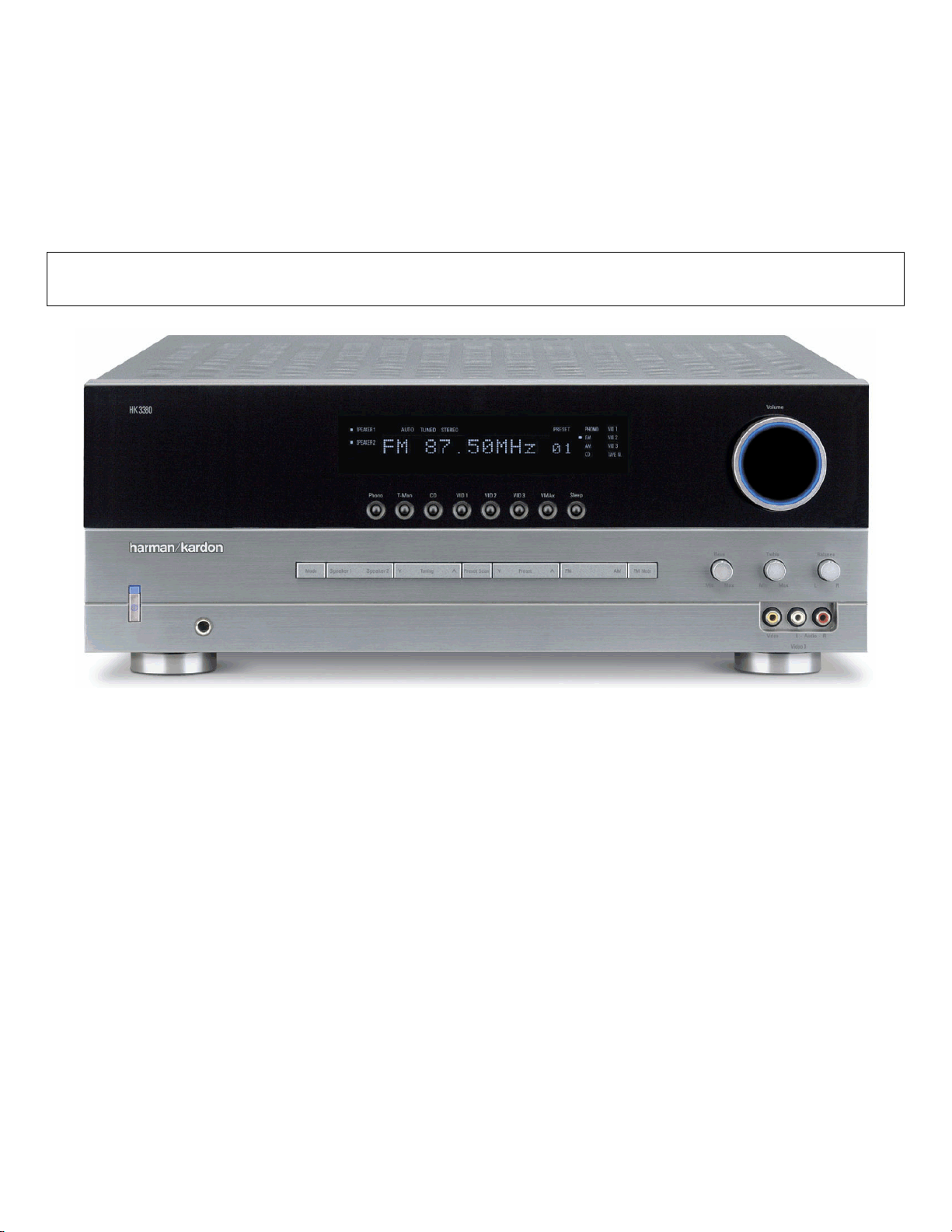
HK3380
STEREO RECEIVER
SERVICE MANUAL
ESD WARNING…………………………....…….2
LEAKAGE TESTING………………..….…..…....3
SPECIFICATIONS ……………………………....4
FRONT PANEL CONTROLS ……………… ….5
REAR PANEL CONNECTIONS ………….....…8
REMOTE CONTROL FUNCTIONS ………..…10
TROUBLESHOOTING GUIDE…...……………12
PROCESSOR RESET……………………….…12
AMPLIFIER BIAS ADJUSTMENT……….…….13
BULLETIN HK2003-10……………………. …..14
BULLETIN HK2004-02……………………. …..16
harman/kardon, Inc.
250 Crossways Park Dr.
CONTENTS
DISASSEMBLY PROCEDURES………………17
EXPLODED VIEW …………………….………..20
BLOCK DIAGRAM…………..……….……….…21
FRONT PANEL DISPLAY..……….……….……22
IC DESCRIPTIONS/PINOUTS…………………26
ELECTRICAL PARTS LIST …………..………..40
PCB DRAWINGS……………………….…….…45
SCHEMATICS………………….…….….………47
WIRING DIAGRAM…………………………..….53
PACKAGE…………………………………….….54
Woodbury, New York 11797 Rev
2 2/2006
Page 2
HK3380 harman/kardon
2
Some semiconductor (solid state) devices can be damaged easily by static electricity. Such components commonly are called
Electrostatically Sensitive (ES) Devices. Examples of typical ES devices are integrated circuits and some field effect transistors and
semiconductor "chip" components.
The following techniques should be used to help reduce the incidence of component damage caused by static electricity.
1. Immediately before handling any semiconductor component or semiconductor-equipped assembly, drain off any electrostatic charge on
your body by touching a known earth ground. Alternatively, obtain and wear a commercially available discharging wrist strap device,
which should be removed for potential shock reasons prior to applying power to the unit under test.
2. After removing an electrical assembly equipped with ES devices, place the assembly on a conductive surface such as aluminum foil, to
prevent electrostatic charge build-up or exposure of the assembly.
3. Use only a grounded-tip soldering iron to solder or unsolder ES devices.
4. Use only an anti-static solder removal device. Some solder removal devices not classified as "anti-static" can generate electrical charges
sufficient to damage ES devices.
5. Do not use freon-propelled chemicals. These can generate electrical change sufficient to damage ES devices.
6. Do not remove a replacement ES device from its protective package until immediately before you are ready to install it. (Most replacement
ES devices are packaged with leads electrically shorted together by conductive foam, aluminum foil or comparable conductive material.)
7. Immediately before removing the protective material from the leads of a replacement ES device, touch the protective material to the
chassis or circuit assembly into which the device will be installed.
CAUTION :
8. Minimize bodily motions when handling unpackaged replacement ES devices. (Otherwise harmless motion such as the brushing together
or your clothes fabric or the lifting of your foot from a carpeted floor can generate static electricity sufficient to damage an ES devices.
Be sure no power is applied to the chassis or circuit, and observe all other safety precautions.
Each precaution in this manual should be followed during servicing.
Components identified with the IEC symbol in the parts list are special significance to safety. When replacing a component identified with
, use only the replacement parts designated, or parts with the same ratings or resistance, wattage, or voltage that are designated in the
parts list in this manual. Leakage-current or resistance measurements must be made to determine that exposed parts are acceptably
insulated from the supply circuit before retuming the product to the customer.
Page 3

HK3380 harman/kardon
3
Before returning the unit to the user, perform the following safety checks :
1. Inspect all lead dress to make certain that
leads are not pinched or that hardware is not
lodged between the chassis and other metal
parts in the unit.
2. Be sure that any protective devices such as
nonmetallic control knobs, insulating fish-
papers, cabinet backs, adjustment and
compartment covers or shields, isolation
resistor-capacity networks, mechanical
insulators, etc. Which were removed for the
servicing are properly re-installed.
3. Be sure that no shock hazard exists ; check for leakage
current usingSimpson Model 229 Leakage Tester, standard
equipment item No. 21641, RCA Model WT540A or use
alternate method as follows : Plug the power cord directly
Into a 120 volt AC receptacle (do not use an Isolation
Transformer for this test). Using two clip leads, connect a
1500 ohms,10watt Resistor paralleledby a 0.15uFcapacitor, in serieswith all exposedmetal cabinet partsand a knownearth ground, such
as a water pipe or conduit. Use a VTVM or VOM with 1000 ohms per volt, or higher sensitivity to measure the AC voltage drop across the
resistor. (See diagram) Move the resistor connection to each exposed metal part having a return path to the chassis (antenna, metal,
cabinet, screwheads, knobsand control shafts, escutcheon, etc.) and measurethe ACvoltage drop across the resistor. (This testshould be
performed withthe 0.35 volt RMS ormore is excessiveand indicates a potential shockhazard which must be corrected before returning the
unit to the owner.
Page 4

18 TECHNICAL SPECIFICATIONS
HK 3380 TECHNICAL SPECIFICATIONS
Audio Section
Stereo Mode
Continuous Average Power (FTC)
80 Watts per channel,20Hz–20kHz
@ < 0.07% THD,both channels driven into 8 ohms
100 Watts per channel,20Hz–20kHz
@ < 0.2% THD,both channels driven into 4 ohms
Input Sensitivity/Impedance
Linear (High Level) 200mV/47k ohms
Signal-to-Noise Ratio (IHF-A) 95dB
Frequency Response
@ 1W (+0dB,–3dB) 10Hz – 110kHz
High Instantaneous
Current Capability (HCC) ±42 amps
Transient Intermodulation
Distortion (TIM) Unmeasurable
Rise Time 16µsec
Slew Rate 40V/µsec
FM Tuner Section
Frequency Range 87.5 –108MHz
Usable Sensitivity IHF 1.12µV /13.5dBf
Signal-to-Noise Ratio Mono/Stereo 73/72dB
Distortion Mono/Stereo 0.3/0.4%
Stereo Separation 40dB @ 1kHz
Selectivity ±400kHz, 65dB
Image Rejection >80dB
IF Rejection >100dB
Tuner Output Level 1kHz,±100kHz, Dev 500mV
AM Tuner Section
Frequency Range 520 –1720kHz
Signal-to-Noise Ratio >40dB
Usable Sensitivity Loop 500µV/M
Distortion 1kHz, 50% Mod 0.8%
Selectivity ±10kHz, >25dB
Video Section
Television System NTSC/PAL/SECAM
Signal Format Composite
Input Level 1Vp-p
Input Impedance 75 ohms,unbalanced
Sync Polarity Negative
Output Level 1Vp-p
Output Impedance 75 ohms,unbalanced
Video Frequency Response 10Hz – 10MHz
General
Power Requirement AC 120V/60Hz
Power Consumption 3W standby,200W maximum
(both channels driven)
Dimension (Max) (Product) (Shipping)
Width 17.4 inches (442mm) 21.5 inches (545mm)
Height 6.6 inches (168mm) 9.9 inches (251mm)
Depth 15 inches (382mm) 17.9 inches (455mm)
Weight 20.9 lb (9.48kg) 25.1 lb (11.41kg)
Depth measurement includes knobs,buttons and terminal connections.
Height measurement includes feet and chassis.
All features and specifications are subject to change without notice.
Harman Kardon and Power for the Digital Revolution are
registered trademarks of Harman International Industries,Incorporated.
4
HK3380 harman/kardon
Page 5
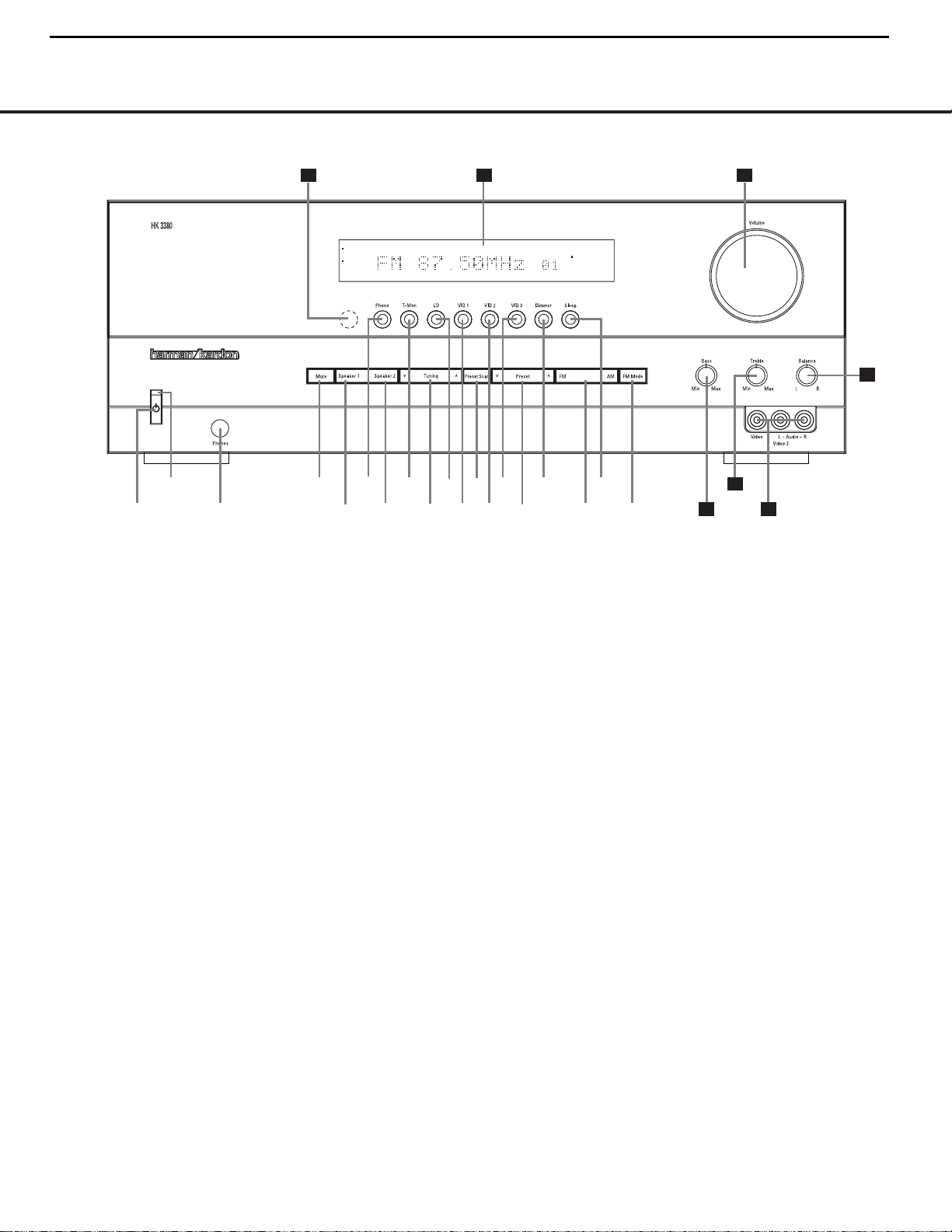
FRONT-PANEL CONTROLS 5
FRONT-PANEL CONTROLSFRONT-PANEL CONTROLS
SPEAKER 2
SPEAKER 1
PHONO
CD
FM
VID 1
TAPE M.
VID 2
PRESET
AM
VID 3
AUTO TUNED STEREO
6
8
@
$^
*
79)!# %
&
(
2
3
1
4
5
20 22
23
242526
21
1 System Power Control
2 Power Indicator
3 Headphone Jack
4 Mute
5 Speaker 1 Selector
6 Phono Input Selector
7 Speaker 2 Selector
8 T-Mon Input Selector
9 Tuning Button
) CD Input Selector
! Video 1 Input Selector
@ Preset Scan
# Video 2 Input Selector
$ Video 3 Input Selector
% Preset Selector
^ Dimmer Button
& FM/AM Selector
* Sleep Button
( FM Mode Selector
Ó Bass Control
Ô Treble Control
Video 3 Audio/Video Input
Ò Balance Control
Ú Volume Control
Û Information Display
Ù Remote Sensor Window
1 System Power Control: Press this button to turn
on the HK 3380; press it again to turn the unit off.The
Power Indicator2above the switch will initially turn
red as the HK 3380 performs a self-check, and it will
change to blue when the unit is on and ready for use.
2 Power Indicator: This LED will light in amber
when the unit is in the Standby mode to signal that
the unit is ready to be turned on.When the unit is
turned on, the indicator will briefly tur n red, and then
change to blue.A red indicator during normal
operation means that the unit is in the Protect mode,
and should be turned off and then checked for a
possible speaker-wire short circuit.
3 Headphone Jack: This jack may be used to listen
to the HK 3380’s output through a pair of headphones.
Be certain that the headphones have a standard 1⁄4"
stereo phone plug.
4 Mute: Press this button to momentarily silence the
speaker output of the HK 3380.The message
MUTE will flash in the Main Informa tion Display
B, and the Mute Indicator K will blink.
5 Speaker 1 Selector: Press this button to
turn the
speakers connected to the
Speaker 1
Output
Terminals
‹ on or off.
6 Phono Input Selector: Press this button to select
the output of a turntable that is connected to the
Phono Inputs™.
7 Speaker 2 Selector: Press this button to
turn
the speakers connected to the
Speaker 2
Output
Terminals
› on or off.
8 T-Mon Input Selector: Press this button to listen
to the output of a tape recorder connected to the
Tape Monitor Inputs¢. The dot to the left of the
Tape Monitor Input Indicator D will flash to indi-
cate that the input source is being monitored when
the HK 3380 is connected to a three-head tape
deck or another unit with off-head playback. See
page 15 for more information on monitoring tape
recordings.
9 Tuning Button: Press the left side of the button to
tune lower-frequency stations and the right side of the
button to tune higher-frequency stations.When a station
with a strong signal is tuned, the
Tuned Indicator I
will light.A brief (1/2-second) press of the button will
manually tune to the next frequency increment, while
pressing and holding the button for a longer period will
automatically tune to the next station with a signal
strong enough for acceptable reception.
) CD Input Selector: Press this button to listen
to the output of a CD player connected to the
CD
Audio Inputs
£.
NOTE: To make it easier to follow the instructions that refer to this illustration, a larger copy may be downloaded from the Product Support section for this product
at www.harmankardon.com.
5
HK3380 harman/kardon
Page 6
FRONT-PANEL CONTROLS
6 FRONT-PANEL CONTROLS
! Video 1 Input Selector: Press this button to listen
to and/or view the output of a device connected to the
Video 1 Inputs §.
@ Preset Scan: Press this button to automatically
scan through the stations that have been programmed
in the HK 3380’s memory.The tuner will play five seconds of each station before moving to the next preset
station.To stop the scan when the desired station is
heard, press the button again. If no preset stations
have been programmed into the HK 3380’s memory,
the message
0 PRESET will flash in the Main
Information Display
B when this button is pressed.
(See page 15 for more information on the tuner memory system.)
# Video 2 Input Selector: Press this button to lis-
ten to and/or view the output of a device connected to
the
Video 2 Inputs •.
$ Video 3 Input Selector: Press this button to
listen to and/or view the output of a device connected
to the
Video 3 Inputs ª on either the front or
rear panel. If devices are connected to both the frontand rear-panel
Video 3 Inputs ª ,then the
device connected to the rear-panel
Video 3 Inputs
ª will be selected first, as indicated by the dot to the
left of the
Video 3 Input Indicator D being steadily
lit.To select the device connected to the front-panel
Video 3 Inputs ,press the Video 3 Input Selector
$ again so that the dot to the left of the Video 3
Input Indicator
D flashes.Each subsequent press of
the
Video 3 Input Selector $ will toggle between
the front and rear
Video 3 Inputs ª .
% Preset Selector: Press this button to step up or
down through the list of stations that has been entered
into the preset memory.If no preset stations have
been programmed into the HK 3380’s memory,
the message
0 PRESET will flash in the
Main Information Display B when this button is
pressed. (See page 15 for more information on tuner
programming.)
^ Dimmer Button: Press this button to dim the
front-panel displays and indicators.The first press of
the button will dim the displays to one-half normal
brightness and turn off the blue light inside the
Volume Control Ú,but the Power Indica tor 2
will remain lit.The next press of the Dimmer Button
^ will turn off all displays,including the light inside
the
Volume Control Ú,but the Power Indica tor
2
will remain lit to remind you that the unit is turned
on. Press the button again to return the display to normal brightness.When the panel is dimmed, it will
return to normal brightness after the unit is turned off,
then on again.
& FM/AM Selector: Press this button to select the
tuner as the input to the receiver. Press the left side of
this button to select the FM frequency band, or the
right side to select the AMfrequency band.
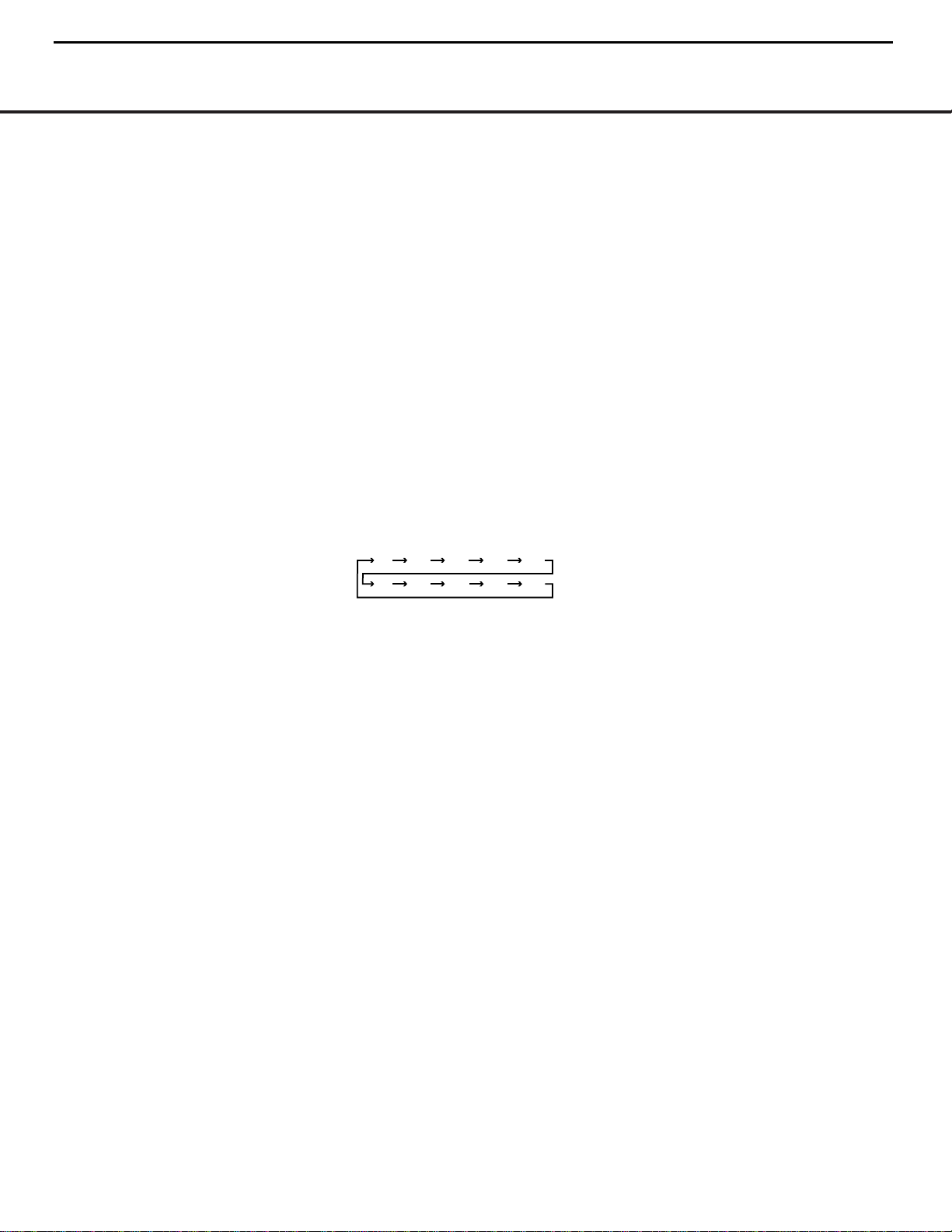
* Sleep Button: Press this button to place the unit
in the Sleep mode.Each press of the button selects
the amount of time that will remain before the unit
automatically goes into the Standby mode,as indicated
by the
Sleep Timer C, in the following order:
( FM Mode Selector: Press this button to select
the Auto Stereo or Mono mode for FM tuning. In the
Auto Stereo mode,the
Auto Indicator J and Stereo
Indicator
H
will light, and stereo reception will be
provided when stations are transmitting stereo signals.
In the Mono mode,the left and right signals from
stereo broadcasts will be mixed together and reproduced through all channels.Select Mono mode for
better reception of weak signals.
Ó Bass Control: Turn this control to modify the lowfrequency output of the left/right channels by as much
as ±10dB.Set this control to a suitable position for
your taste and room acoustics.
Ô Treble Control:Turn this control to modify the
high-frequency output of the left/right channels by as
much as ±10dB.Set this control to a suitable position
for your taste and room acoustics.
Video 3 Audio/Video Inputs: The front-panel
Video 3 Audio/Video Inputs are convenient for
connecting devices that will only be used temporarily,
such as when you wish to view vacation videos directly
from the camera. Connect these jacks to the PLAY/
OUT jacks of an audio or video device,such as a
camcorder or video-game console.To select the frontpanel inputs,press the
Video 3 Input Selector $
repeatedly until the dot to the left of the Video 3
Input Indicator
D flashes.In order to view the video
signal of a video device connected to this input,
remember to connect the
Video Monitor Output ·
to the video input of your TV or video display.
Ò Balance Control: Turn this control to change the
relative volume for the front left/right channels.
Ú Volume Control: Turn the knob clockwise to
increase volume,counterclockwise to decrease
volume.When the unit has been muted by pressing
the
Mute Button 4®, the message MUTE will
flash in the
Main Information Display B, and the
Mute Indicator K will blink.
Û Information Display: This display delivers mes-
sages and status indications to help you operate the
receiver.
Ù Remote Sensor Window:The sensor behind
this window receives infrared signals from the remote
control.Aim the remote at this area and do not block
or cover it unless an external remote sensor is
installed.
90
min80min70min60min50min
40
min
30
min20min10min
OFF
6
HK3380 harman/kardon
Page 7
FRONT-PANEL INFORMATION DISPLAY
FRONT-PANEL INFORMATION DISPLAY 7
F E
G
A
B
H
IJK
C
SPEAKER 2
SPEAKER 1
PHONO
CD
FM
VID 1
TAPE M.
VID 2
PRESET
AM
VID 3
AUTO TUNED STEREO
MUTE
SLEEP
MEMORY
D
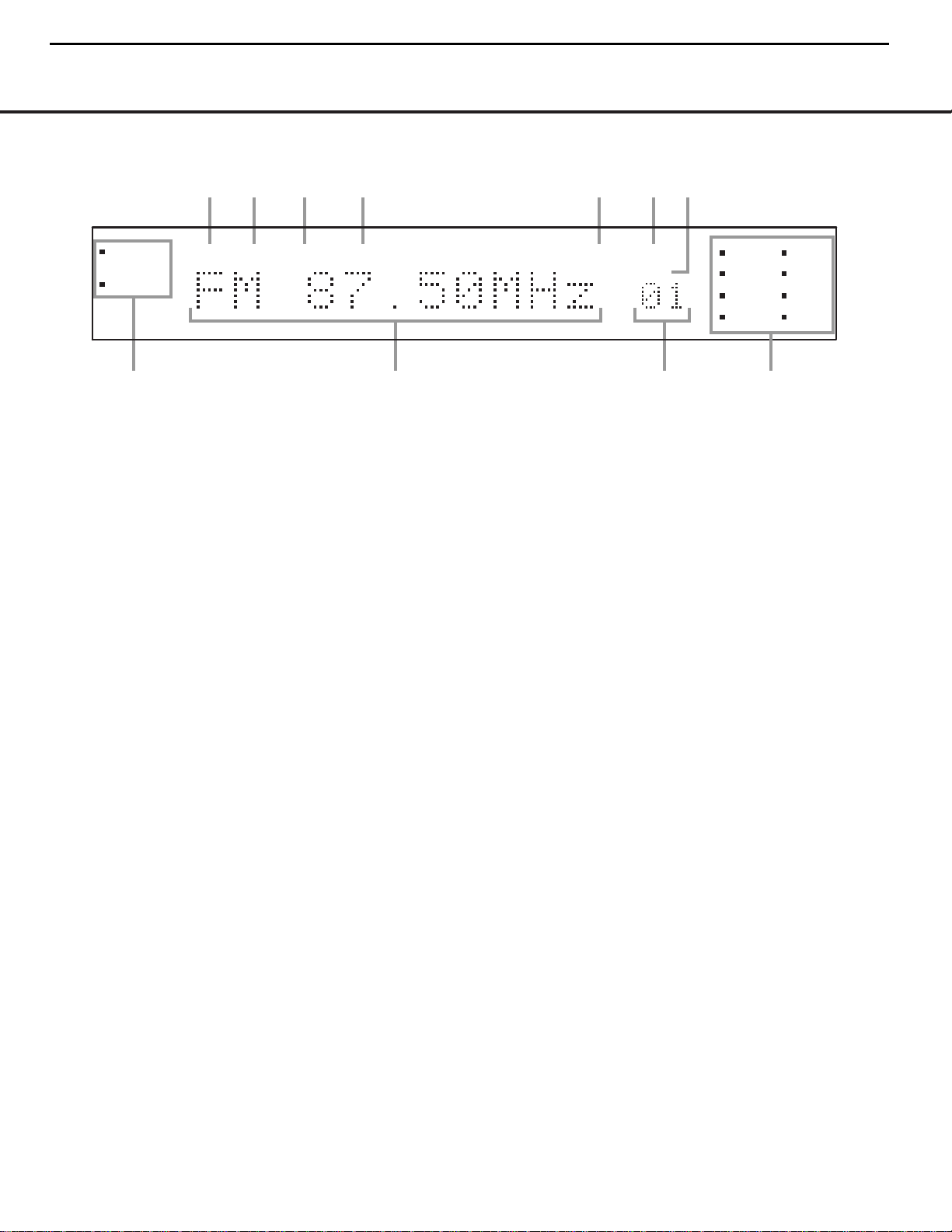
A Speaker Selection Indicators
B Main Information Display
C Preset Number/Sleep Timer
D Input Indicators
E Sleep Indicator
F Preset Indicator
G Memory Indicator
H Stereo Indicator
I Tuned Indicator
J Auto Indicator
K Mute Indicator
A Speaker Selection Indicators: The dot to the
left of the indicator for each speaker pair will light
when that pair is active.Press the
Speaker 1 5 or
Speaker 2 7 selectors to activate either or both
pairs of speakers.
B Main Information Display: This display shows
messages relating to the status,input source,tuner or
other aspects of the HK 3380’s operation.
C Preset Number/Sleep Timer:When the tuner is
in use,these numbers indicate the specific preset
memory location in use.(See page 15 for more information on preset stations.) When the Sleep function is
in use,these numbers show how many minutes
remain before the unit goes into the Standby mode.
D Input Indicators: The dot to the left of the name
of the device that is currently the source input for the
HK 3380 will light.
When the device connected to the
Tape Monitor
Inputs
¢ has been selected, the dot to the left of
the
Tape Monitor Input Indicator D will flash to
indicate that you are hearing the signal the HK 3380
is receiving from the device connected to the
Tape
Monitor Inputs
¢.The dot to the left of the Input
Indicator
D for the last-selected source input will
remain lit. (See page 15 for more information on
monitoring tape recordings.)
E Sleep Indicator: This indicator lights when the
Sleep function is in use.The numbers in the Preset
Number/Sleep Timer Indicators will show the minutes
remaining before the HK 3380 goes into the Standby
mode.(See page 14 for more information on the
Sleep function.)
F Preset Indicator: This indicator lights when the
tuner is in use to show that the
Preset Number/
Sleep Timer
C is showing the station’s preset
memory number.(See page 15 for more information
on tuner presets.)
G
Memory Indicator: This indicator flashes when
entering presets and other information into the tuner’s
memory.
H Stereo Indicator: This indicator lights when an FM
station is being tuned in stereo.
I
Tuned Indicator:
This indicator lights when a station is being received with sufficient signal strength to
provide acceptable listening quality.
J Auto Indicator: This indicator lights when the
tuner’s Auto Stereo mode is in use.
K Mute Indicator: This indicator flashes to remind
you that the HK 3380’s output has been silenced by
pressing the
Mute Button 4®.Press the Mute
button again to return to the previously selected
output level.
NOTE: To make it easier to follow the instructions that refer to this illustration, a larger copy may be downloaded from the Product Support section for this product
at www.harmankardon.com.
NOTE: To make it easier to follow the instructions that refer to this illustration, a larger copy may be downloaded from the Product Support section for this product
at www.harmankardon.com.
7
HK3380 harman/kardon
Page 8
REAR-PANEL CONNECTIONS
8 REAR-PANEL CONNECTIONS
‚
⁄
∞
§
•
¶
ª
¢
™
£¡
¤
‹
fl°·b a ‡
fi
›
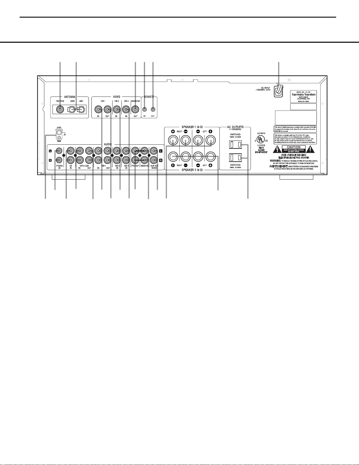
¡ Phono Ground
™ Phono Inputs
£ CD Audio Inputs
¢ Tape Monitor Play/In
∞ Tape Monitor Record/Out
§ Video 1 Audio/Video Play/In
¶ Video 1 Audio/Video Record/Out
• Video 2 Audio/Video Inputs
ª Video 3 Audio/Video Inputs
‚ Preamp Out
⁄ Main In
¤ Subwoofer Out
‹ Speaker 1 Ter minals
› Speaker 2 Ter minals
fi Accessory Outlets
fl Power Cable
‡ Remote IR Out
° Remote IR In
· Video Monitor Output
a AM Antenna
b FM Antenna
¡ Phono Ground: Connect the ground wire from a
turntable to this terminal to reduce system hum.
™ Phono Inputs: Connect the outputs of your
turntable or tonearm to these jacks.Only Moving
Magnet (MM)-type cartridges may be used.
£ CD Audio Inputs: Connect these jacks to the
output of a compact disc player or CD changer.
¢ Tape Monitor Play/In: Connect these jacks to
the Play/Out jacks of an audio recorder.
∞ Tape Monitor Record/Out: Connect these jacks
to the Rec/In jacks of an audio recorder.
NOTE: When these jacks are connected to a threehead recorder or another device with off-head playback, it will be possible to monitor the source being
recorded.
§ Video 1 Audio/Video Play/In: Connect these
jacks to the PLAY/OUT jacks of an audio or video
device,such as a VCR or DVD player. In order to
view the video signal of a video device connected
to this input, remember to connect the
Video Monitor
Output
· to the video input of your TV or video
display.
¶ Video 1 Audio/Video Record/Out: Connect
these jacks to the Rec/In jacks of an audio or video
recorder.
• Video 2 Audio/Video Inputs: Connect these
jacks to the PLAY/OUT jacks of an audio or video
device,such as a VCR or DVD player. In order to
view the video signal of a video device connected
to this input, remember to connect the
Video Monitor
Output
· to the video input of your TV or video
display.
ª Video 3 Audio/Video Inputs: Connect these
jacks to the PLAY/OUT jacks of an audio or video
device,such as a VCR or DVD player. In order to
view the video signal of a video device connected
to this input, remember to connect the
Video Monitor
Output
· to the video input of your TV or video
display.
‚ Preamp Out: These jacks provide an output for
the left and right channels to an optional external
amplifier. In normal operation, unless an external
power amplifier is used, the jumper pins should
remain connected between these jacks and the
Main In Jacks ⁄.
⁄ Main In: These jacks are the input to the HK 3380’s
power amplifier.Unless an external power amplifier is used,
the jumper pins should remain connected between these
jacks and the
Preamp Out Jacks ‚.
NOTE: To make it easier to follow the instructions that refer to this illustration, a larger copy may be downloaded from the Product Support section for this product
at www.harmankardon.com.
8
HK3380 harman/kardon
Page 9

REAR-PANEL CONNECTIONS 9
REAR-PANEL CONNECTIONS
¤ Subwoofer Out: Connect these jacks to the
line-level inputs of a powered subwoofer. If an external
subwoofer amplifier is used, connect these jacks to
the subwoofer amplifier inputs.When a single, mono
subwoofer is used, or if the subwoofer or its amplifier
has only a single line-level input jack, make the
connection to the bottom jack on the HK 3380.
‹ Speaker 1 Terminals: Connect these terminals
to the appropriate terminals on your speakers.
› Speaker 2 Terminals: Connect these terminals
to the appropriate terminals on your speakers.
fi Accessor y Outlets: These outlets may be used
to power low-current-draw devices such as CD players
or cassette decks.The power to these outlets remains
on as long as the receiver itself is on.When the
receiver is placed in the Standby mode,power to
these outlets is removed.
NOTE: The power consumption of the devices
plugged into these outlets should not exceed
100 watts.
fl Power Cable: Connect the AC plug to a non-
switched AC wall output.
‡ Remote IR Out: This connection permits the IR
sensor in the receiver to serve other remote-controlled
devices.Connect this jack to the “IR In”jack on
Harman Kardon (or other compatible) equipment.
° Remote IR In: If the HK 3380’s front-panel
IR sensor is blocked due to cabinet doors or other
obstructions,an external IR sensor may be used.
Connect the output of the sensor to this jack.
· Video Monitor Output: Connect this jack to the
composite video input of your TV or video display
device.Doing so will enable you to view the video
signal of a properly connected video source device,
when that source input is selected.When an audioonly source is selected, the
Video Monitor Output
· will not transmit a video signal.
a AM Antenna: Connect theAM loop antenna
supplied with the receiver to these terminals.If an
external AM antenna is used, make connections to
the
AM and GND terminals in accordance with the
instructions supplied with the antenna.
b FM Antenna: Connect an indoor or external FM
antenna to this terminal.
9
HK3380 harman/kardon
Page 10
10 REMOTE CONTROL FUNCTIONS
REMOTE CONTROL FUNCTIONS
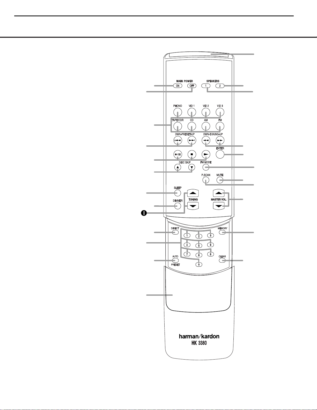
å Main Power On
∫ Main Power Off
ç Source Selectors
∂ Preset Up/Down
≠ Transport Controls
ƒ Disc Skip
© Sleep Button
˙ Dimmer Button
î Tuning
∆ Direct Button
˚ Numeric Keys
¬ Auto Preset
µ Secondary Control Cover
Ñ Clear Button
ø Memory Button
π Master Volume
œ Preset Scan Button
® Mute Button
ß FM Mode Button
† Enter Button
Ü Tuning Up/Down
√ Speaker 1 Selector
∑ Speaker 2 Selector
≈ Transmitter Window
NOTES:
• The function names shown here are each button’s
feature when used with the HK 3380. Most buttons
have additional functions when used with other
devices.See page 16 for a list of these functions.
• To make it easier to follow the instructions that refer
to this illustration, a larger copy may be downloaded
from the Product Support section for this product at
www.harmankardon.com.
Ñ
ø
å
©
˙
˚
¬
µ
π
∫
ç
∂
≠
ƒ
®
∑
†
≈
√
œ
ß
Ü
∆
10
HK3380 harman/kardon
Page 11

REMOTE CONTROL FUNCTIONS 11
REMOTE CONTROL FUNCTIONS
å Main Power On: When the HK 3380 is in the
Standby mode,as indicated by the
Power Indicator
2 glowing amber,press this button to turn the
HK 3380 on.
∫ Main Power Off: When the HK 3380 is turned
on, press this button to place it in the Standby mode.
In this condition, the unit is still connected to AC Power.
ç Source Selectors: Press these buttons to select an
input source for the HK 3380.
NOTE:The first press of the Video 3 Source Selector
ç will select the device connected to the rear-panel
Video 3 Audio/Video Inputsª.Press the Video 3
Source Selector
ç again until the dot to the left of the
Video 3 Input Indicator D flashes to select the device
connected to the front-panel
Video 3 Audio/Video
Inputs
.Each additional press of the Video 3 Source
Selector
ç will toggle between the front- and rear-panel
Video 3 Audio/Video Inputsª.
∂ Preset Up/Down: When the tuner is in use, these
buttons scroll through the stations that have been programmed into the HK 3380’s
memory.These buttons
also control the track Skip
Up/Down on compatible
Harman Kardon compact disc players/changers.
≠ Transport Controls:These buttons are used to
control the Play,Stop,Pause and Record functions on
compatible Harman Kardon CD/DVD players/changers
and CD recorders.
ƒ Disc Skip:These buttons do not have any func-
tions when controlling the HK 3380, but they operate
the Disc Skip functions of compatible Harman Kardon
CD/DVD changers.
© Sleep Button: Press this button to place the unit
in the Sleep mode.Each press of the button selects
the amount of time that will remain before the unit will
automatically go into the Standby mode,as shown in
the
Sleep Timer C, in the following order:
˙ Dimmer Button: Press this button to dim the
front-panel displays and indicators.The first press of
the button will dim the displays to one-half normal
brightness and turn off the blue light inside the
Volume Control Ú,but the Power Indica tor 2
will remain lit.The next press of the Dimmer Button
^ will turn off all displays,including the light inside
the
Volume Control Ú,but the Power Indica tor
2
will remain lit to remind you that the unit is turned
on. Press the button again to return the display to normal brightness.When the panel is dimmed, it will
return to normal brightness after the unit is turned off,
then on again.
î Tuning: Press these buttons to tune up or
down through a selected frequency band.A brief
(1/2-second) press of the button will manually tune
to the next frequency increment, while pressing and
holding the button for a longer period will automatically
tune to the next station with a signal strong enough
for acceptable reception.
∆ Direct Button: Press this button to select a radio
station by entering its frequency using the
Numeric
Keys
K. (See page14 for more information.)
˚ Numeric Keys:These buttons serve as a 10-
button numeric keypad to enter tuner preset positions
or to tune stations directly.
¬ Auto Preset: When the tuner and FM band have
been selected, this button may be used to automatically
program the tuner presets for all active stations.To start
the auto preset scan, press and hold the button. Note
that the
Memory G and Preset F indicators will
flash.After a few seconds,the tuner will start to “look”
for active stations,as shown by increasing frequency
numbers in the
Main Information Display B.
Release the button and note that the tuner will briefly
stop at each active station and add a preset number to
the memory.If the FM tuner finds fewer than 30 FM
stations with acceptable signal strength, the Auto Preset
tuning will scan two more cycles or until the remaining
vacant preset memory spaces have been filled with
those found in the first scan.The scan will stop when
all 30 preset memory spaces have been filled or when
three scans through the band have been completed.
µ Secondary Control Cover: This sliding cover
normally is in the “up”position so that it hides the
secondary controls.To access these controls,place
your thumb on the small recessed area at the top
center of the control, and gently press the cover down
and toward you.
Ñ Clear Button:This button is used to clear preset
memory information for the HK 3380’s tuner. (See
page 15 for more information on tuner presets.)
ø Memory Button: Press this button to open a
memory position that stores a preset location for the
HK 3380’s tuner.(See page15 for more infor mation
on tuner presets.)
π Master Volume: Press these buttons to raise or
lower the HK 3380’s volume.
œ Preset Scan Button: Press this button to auto-
matically scan through the list of stations that are
programmed into the HK 3380’s tuner memory.When
the button is pressed, each preset station will play
for five seconds before the next station is selected.
Press the button again when the desired station is
heard, to stop the preset scan.
® Mute Button: Press this button to momentarily
silence the HK 3380.
ß FM Mode Button: Press this button when the
tuner is in use in the FM band to switch to monaural
reception if the station is weak and noisy.(See page14
for more information.)
† Enter Button:This button has no function on the
HK 3380, but may be used as the Enter key for a
compatible Harman Kardon DVD Player or as the
Random Play button for a compatible CD Player. (See
page 16 for more information on using the remote to
control other devices.)
Ü Tuning Up/Down:When the tuner is in use,these
buttons will tune up or down through the selected frequency band.A brief (1⁄2-second) press of the button
will manually tune to the next frequency increment, while
pressing and holding the button for a longer period will
automatically tune to the next station with a signal strong
enough for acceptable reception.These buttons will
also control Fast Forward and Fast Reverse (or Rewind)
for compatible Harman Kardon compact disc players/
changers.
√ Speaker 1 Selector: Press this button
to turn the
speakers connected to the
Speaker 1
Output
Terminals
‹ on or off.
∑ Speaker 2 Selector: Press this button
to turn the
speakers connected to the
Speaker 2
Output
Terminals
› on or off.
≈ Transmitter Window: Point this area of the
remote toward the receiver when using the remote.
90
min80min70min60min50min
40
min
30
min20min10min
OFF
11
HK3380 harman/kardon
Page 12

TROUBLESHOOTING GUIDE 17
TROUBLESHOOTING GUIDE
This unit is designed for trouble-free operation. Most problems users encounter are due to operating errors. So, if you have a problem, first check this list for a possible solution.
If the problem persists,consult your authorized Harman Kardon service center.
If the problem is . . . Make sure that the . . .
No lights appear when POWER button is pressed Unit is plugged into a live outlet
No sound is heard Unit has not been muted
Correct input function selector button has been pressed
Volume is turned up
Speakers have been turned on using the Speaker Selectors
Headphones are not in use
Jumper pins are in place,unless an external amplifier is in use
No output from one or more channels Cables are not defective: check/replace speaker cables
Tuner sound has a large amount of interference,or Antenna is properly connected
The “Stereo”display is not illuminated, or Antenna is properly located
Tuner sound distorts and/or volume level is too low Antenna is set in the proper direction
Antenna is adequate to receive the desired station
Tuner is intermittent or continuously buzzing or hissing Unit is away from fluorescent lights,TVs,motors and
other electrical appliances
Remote does not function correctly Batteries are not weak, and replace them if necessar y
Room lighting is not overly bright
Cassette or CD sounds distorted Cassette deck or CD player has not been plugged into the
Phono Input ™
(only use the outputs of a turntable or tone arm with the Phono Input ™)
Turntable sounds distorted Turntable has been plugged into the
Phono Input ™,
as the other inputs are not compatable with turntable signal levels
No video image Video source unit’s video ouput is properly connected,the source is turned on and the correct video
input on the HK 3380 has been selected
Video Monitor Output · is connected to a TVor video display,and that the TV is turned on and the
proper input on the TV has been selected
12
HK3380 harman/kardon
Memory Backup
This product is equipped with a non-volatile EEPROM (Electrically Erasable and Programmable Read-Only
Memory) that preserves tuner presets and system configuration information without the unit being connected to
a main power source for any prolonged period of time.
Processor Reset
In the rare case where the unit’s operation or the displays seem abnormal, the cause may involve the erratic
operation of the system’s memory or microprocessor.
To correct this problem, first unplug the unit from the AC wall outlet and wait at least thirty minutes. After the
pause, reconnect the AC power cord and check the unit’s operation. If the system still malfunctions, a system
reset may clear the problem. To reset the system, first turn the HK 3380 off by pressing the System Power
Control. Next, press and hold the front-panel Mute Button for at least 4 seconds. The Main Information Display
will briefly show the word RESET, and then return to normal operation. When the system is reset in this
fashion, all tuner presets will be lost and must be reentered. If the system is still operating incorrectly, there
may have been an electronic discharge or severe AC line interference that has corrupted the memory or
microprocessor. If these steps do not solve the problem, consult an authorized Harman Kardon service center.
Page 13
13
HK3380 harman/kardon
Page 14
14
HK3380 harman/kardon
harman/kardon Service Bulletin
Service bulletin # H/K2003-10 December 2003
To: All harman/kardon Service Centers
Models: AVR130, AVR230, AVR330, HK3380, HK3480
Subject: Volume Level Changes
On early versions of the AVR130,AVR230,AVR330,HK3380,HK3480, when the volume control is turned, the
volume level and display may be erratic, and not track accurately, or the level may progress in an unintended
direction. This may happen on a random basis and depends on where the volume control knob is positioned
after a volume adjustment. During a running production change, new volume encoders were installed.
In the event you receive an AVR model listed above with the complaint “The volume control on my
receiver does not track accurately when turned”, perform the following procedure:
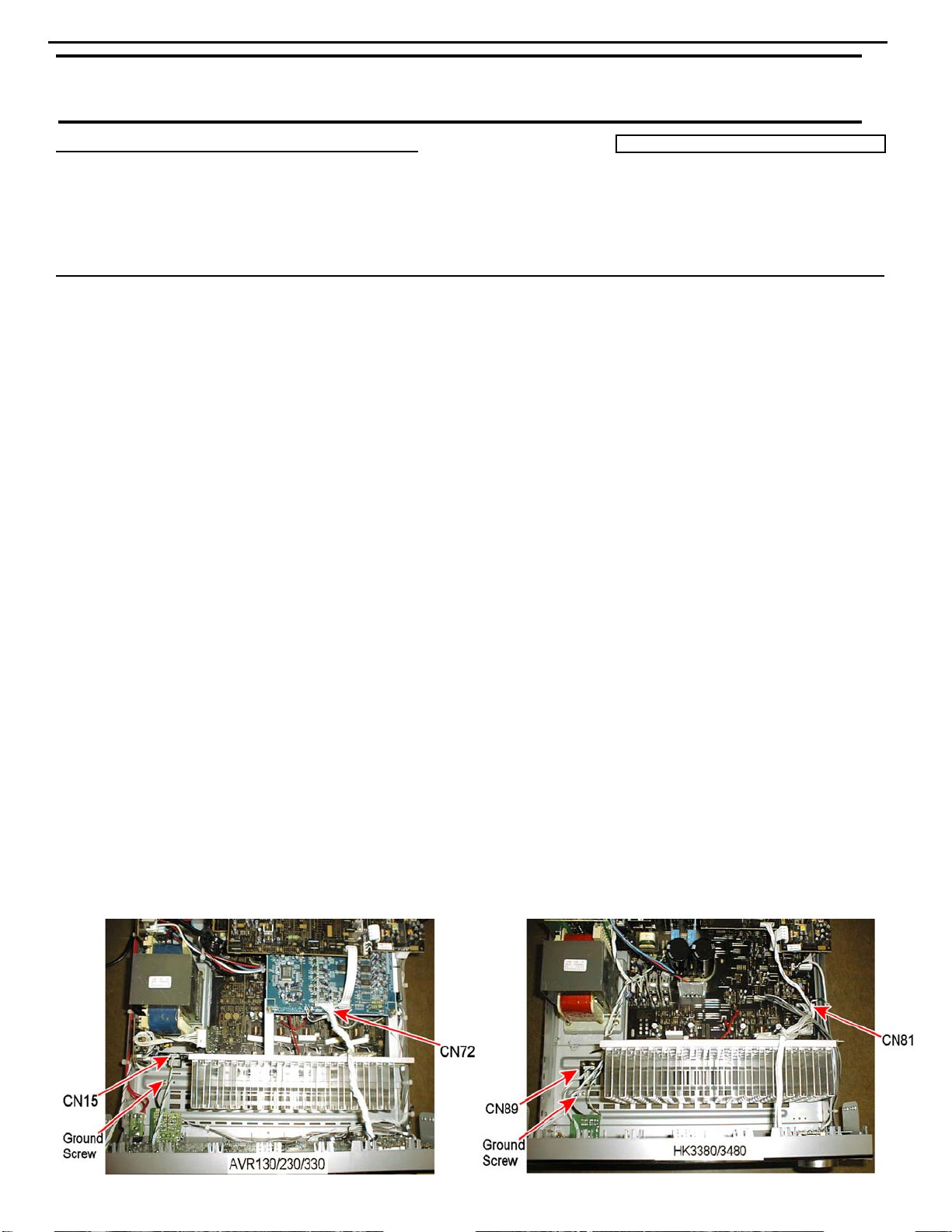
REPLACE VR74 (AVR130/230/330) or VR81 (HK3380/3480) VOLUME ENCODER
Note: It is important that the various screws do not get mixed up and inserted in other locations upon reassembly. Make
note or label each removed screw set; keep them apart from other screw sets.
1) Remove the top cover, (13) Phillips screws.
2) Remove the volume, bass, treble and balance knobs by pulling them straight out and off. If a tool is
necessary for removal of the smaller knobs, make sure the jaws are insulated to avoid knob damage.
3) Remove the (10) Phillips screws holding the front panel ass’y to the chassis: (6) at the bottom and (4) at
the sides.
4) Cut all plastic cable ties that would prevent you detaching the front panel ass’y from the chassis. Draw a
diagram if necessary, for a location reminder, to aid reassembly.
5) Unplug connector CN15 (6 cond) or CN89 (7 cond) at the left side of the unit. See below.
6) Remove single ground screw at the left side of the unit, near CN15 or CN89. (Black wire)
7) Unplug connector CN72 (32 cond) or CN81 (20 cond) on the DSP PCB, coming from the top of the front
panel ass’y. See below.
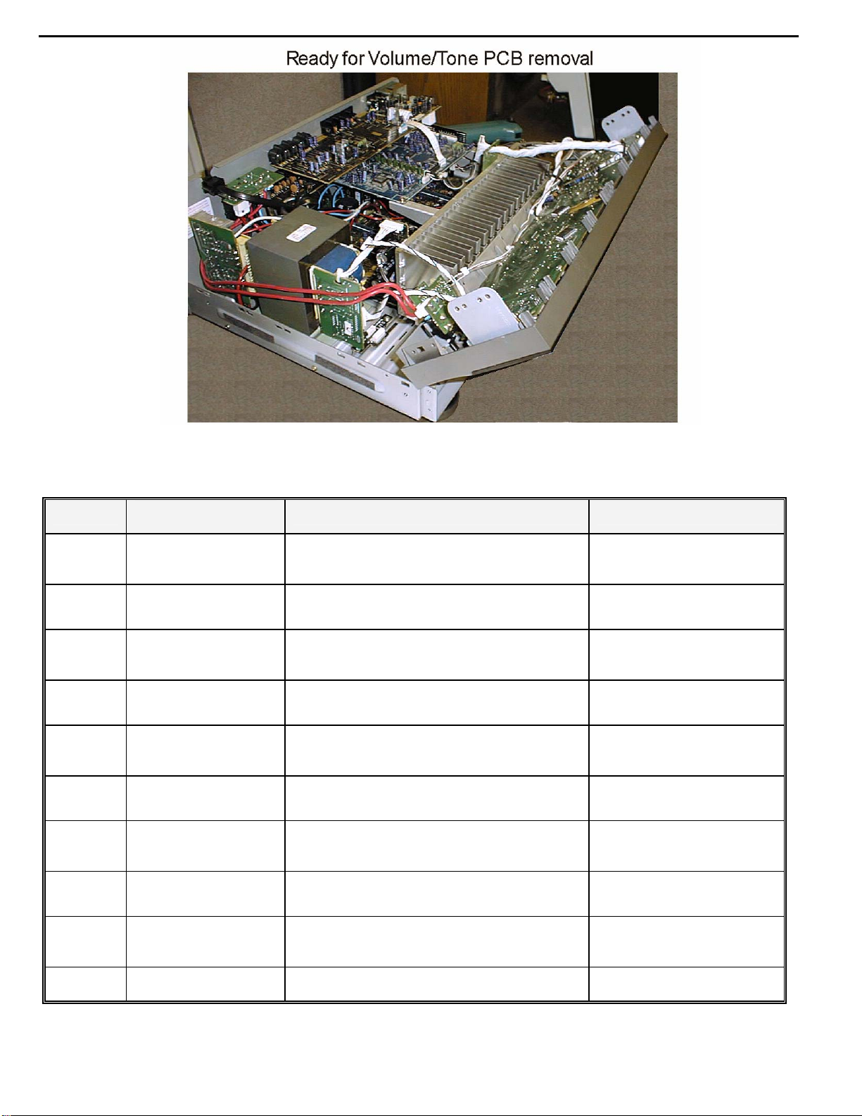
8) There should now be enough slack in the connecting cables to lift and detach the front panel ass’y from
the chassis. Pull the front panel as far away as the remaining connecting wires will allow, enough to tilt
and gain access to the rear of the Tone/Volume PCB. See illustration Page 2.
9) Remove the (10) screws or (9) screws holding the Tone/Volume PCB to the front panel.
10) Detach and pull back the PCB; unplug top connector CN84 (7 cond) or CN83 (4 cond) if necessary.
11) Remove and replace VR74 or VR81 (5 soldered pads) with hk part# HSR2A029Z.
12) Reassemble in reverse order, taking care to replace all connectors, cable ties, and ground screw.
13) Power up receiver, and test volume control to assure setting no longer changes settings by itself, or when
the volume knob is tapped.
Warranty labor rate: MAJOR repair
Page 15
15
HK3380 harman/kardon
Model
AVR130
AVR130
AVR230
AVR230
AVR330
AVR330
HK3380
HK3380
HK3480
HK3480
Serial Number
120V
AN0006-01000
to
AN0006-13800
AN0006-13801
and above
AN0007-01000
to
AN0007-11400
AN0007-11401
and above
AN0008-01000
to
AN0008-08524
AN0008-08525
and above
AN0015-01000
to
AN0015-02728
AN0015-02729
and above
AN0016-01000
to
AN0016-01864
AN0016-01865
and above
STATUS ACTION
Volume control may not track accurately when
turned; erratic operation
Modified By Factory NONE REQUIRED
Volume control may not track accurately when
turned; erratic operation
Modified By Factory NONE REQUIRED
Volume control may not track accurately when
turned; erratic operation
Modified By Factory NONE REQUIRED
Volume control may not track accurately when
turned; erratic operation
Modified By Factory NONE REQUIRED
Volume control may not track accurately when
turned; erratic operation
Modified By Factory NONE REQUIRED
Change VR74
Rotary encoder
Change VR74
Rotary encoder
Change VR74
Rotary encoder
Change VR81
Rotary encoder
Change VR81
Rotary encoder
Page 16

16
HK3380 harman/kardon
harman/kardon Service Bulletin
Service bulletin # H/K2004-02 April 2004
To: All harman/kardon Service Centers
Model: HK3380/3480
Subject: Silence During Preset Scan - Upgrade
In the event you receive an HK3380 or HK3480 stereo receiver with the complaint: “When the Preset
Scan Function * is activated and the receiver cyles through the list of station presets, there is silence”,
the unit is in need of a software upgrade.
The unit should be sent to the following authorized service center equipped to perform the software upgrade:
HARMAN CONSUMER GROUP DISTRIBUTION CENTER
801 S. 75
TH
AVE.
PHOENIX, AZ. 85043
Attn: Rodney Yee
Model
HK3380
HK3380
HK3380
HK3480 AN0016-035923 and above AN0018-6101 and above Modified by Factory None Required
Serial Number ( 120v)
AN0015-01000
to
AN0015-04456
AN0015-04457 and above AN0017-06101 and above Modified by Factory None Required
AN0016-01000
to
AN0016-03592
Warranty labor rate: MINOR repair
Serial Number ( 230v)
AN0017-01000
to
AN0017-06100
AN0018-01000
to
AN0018-6100
If Silence During Preset
Scan Upgrade is Needed
If Silence During Preset
Scan Upgrade is Needed
Status Action ( upgr ade)
Upgrade Possible
Upgrade Possible
* Preset Scan: Press this button to automatically scan through the stations that have been programmed in the unit’s memory. The
tuner will play five seconds of each station before moving to the next preset station. To stop the scan when the desired station is
heard, press the button again. If no preset stations have been programmed into the unit’s memory, the message 0 PRESET will flash
in the Main Information Display when this button is pressed.
Page 17
HK3380 harman/kardon
17
HK3380/HK3480
Page 18

18
HK3380 harman/kardon
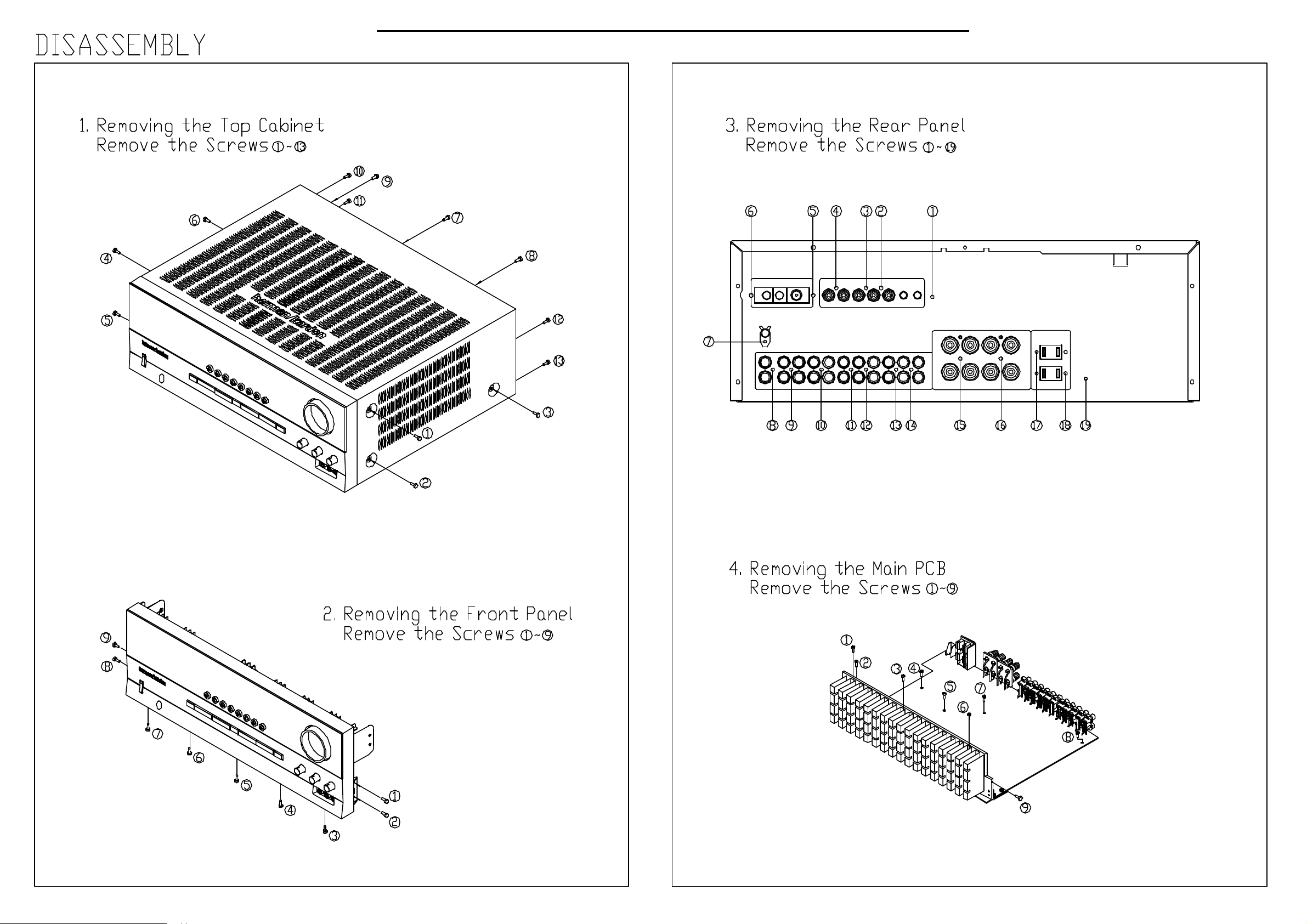
DISASSEMBLY PROCEDURES
<1> TOP-CABINET(21) REMOVAL
1. Remove 13 screws(S1) and then remove the Top-cabinet.
<2> FRONT PANEL ASS’Y REMOVAL
1. Remove the Top-cabinet, referring to the previous step<1>.
2. Disconnect the lead wire(BN71-12P,BN72-5P) on the Tone PCB(38) from connector(CN71,CN72) on the
Main PCB(44).
3. Disconnect the lead wire(BN82-7P) on the Front PCB(37) from connector(CN82) on the Main PCB(44).
4. Disconnect the connector(CN81-20P wire assy) on the Front PCB(37) from connector(CN81)
on the Main PCB(44).
5. Disconnect the lead wire(BN73-3P) on the Phone PCB(40) from connector(CN73) on the Main PCB(44).
6. Disconnect the lead wire(BN89-7P) on the Front PCB(37) from connector(CN73) on the Download PCB(44).
7. Remove 1 screw(S10) and then lead wire(JW73-2P) on the Phone PCB(40).
8. Remove 1 screw(S10) and then lead wire(JW72-1P) on the Tone PCB(38).
9. Remove 9 screws(S1) and then remove the Front Panel ASS’Y.
<3> TONE PCB(38) REMOVAL
1. Remove the Top-cabinet, referring to the previous step<1>.
2. Remove the Front Panel ASS’Y, referring to the previous step<2>.
3. Pull out the Volume Knob ASS’Y & 3 Rotary Knobs(5).
4. Remove 9 screws(S1,S11) and then remove the Tone PCB(38).
5. Disconnect the lead wire(BN83-4P) from connector(CN83) on the Tone PCB(38).
<4>PHONE PCB(40) REMOVAL
1. Remove the Top-cabinet, referring to the previous step<1>.
2. Remove the Front Panel ASS’Y, referring to the previous step<2>.
3. Remove 2 screws(S2,S3) and then remove the Phone PCB(16).
<5>POWER LED PCB(39) REMOVAL
1. Remove the Top-cabinet, referring to the previous step<1>.
2. Remove the Front Panel ASS’Y, referring to the previous step<2>.
3. Remove 2 screws(S2) and then remove the Power led PCB(39).
4. Disconnect the lead wire(BN84-4P) from connector(CN84) on the Power led PCB(39).
<6>FRONT PCB(37) REMOVAL
1. Remove the Top-cabinet, referring to the previous step<1>.
2. Remove the Front Panel ASS’Y, referring to the previous step<2>.
3. Remove the Tone PCB(38), referring to the previous step<3>.
4. Remove the Phone PCB(40), referring to the previous step<4>.
5. Remove the Power led PCB(39), referring to the previous step<5>.
6. Remove 13 screws(S2) and then remove the Front PCB(37).
<7>TUNER MODULE(34) REMOVAL
1. Remove the Top-cabinet, referring to the previous step<1>.
2. Disconnect the connector(CON1-Card cable) from connector(CN26) on the Main PCB ASS’Y(44).
3. Remove 2 screws(S8) and then remove the Tuner Module(34).
Page 19

19
HK3380 harman/kardon
<8>VIDEO PCB(43) REMOVAL
1. Remove the Top-cabinet, referring to the previous step<1>.
2. Disconnect the connector (CN91) on the Main PCB ASS’Y(44) from lead wire(BN91-9P)
on the Video PCB(43).
3. Remove 4 screws(S8,S13) and then remove the Video PCB(43).
<9>DOWNLOAD PCB(42) REMOVAL
1. Remove the Top-cabinet, referring to the previous step<1>.
2. Disconnect the connector (CN89) from lead wire(BN89-7P) on the Front PCB(37).
3. Remove 2 screws(S4) and then remove the Download PCB(42).
<10>POWER TRANS(30) REMOVAL
1. Remove the Top-cabinet, referring to the previous step<1>.
2. Disconnect the connector (CN62,CN63,CN64) on the Trans PCB from lead wire(BN62-2P,BN63-3P,BN64-6P)
on the Main PCB(44).
3. Remove 4 Trans screws(S9) and then remove the Power Trans(30).
<11>MAIN PCB ASS’Y(44) REMOVAL
1. Remove the Top-cabinet, referring to the previous step<1>.
2. Remove the Power Trans(30), referring to the previous step<10>.
3. Disconnect the connector(CN81-20P wire ass’y) from connector(CN81-7P) on the Front PCB(37).
4. Disconnect the connector(CN82) from lead wire(BN82-7P) on the Front PCB(37).
5. Disconnect the connector(CN71) from lead wire(BN71-12P) on the Tone PCB(38).
6. Disconnect the connector(CN72) from lead wire(BN72-5P) on the Tone PCB(38).
7. Disconnect the connector(CN73) from lead wire(BN73-3P) on the Phone PCB(40).
8. Disconnect the connector(CN91) from lead wire(BN91-9P) on the Video PCB(43).
9. Disconnect the connector(CN26-Card cable) from lead wire(CON1) on the Tuner Module(34).
10. Disconnect the connector(CN61) from Power cord(35).
11. Remove 21 screws(S8-11EA, S13-1EA, S4-2EA, S6-2EA, S15-1EA, S12-3EA, S5-1EA) and then
remove the Main PCB ASS’Y(44).
Page 20

HK3380 harman/kardon
20
HK3380 EXPLODED VIEW
Page 21

HK3380 harman/kardon
21
Page 22

HK3380 harman/kardon
22
HCA16ML08-1 (F.I.P) : FIP1
Page 23

HK3380 harman/kardon
23
Page 24

HK3380 harman/kardon
24
Page 25

HK3380 harman/kardon
25
Page 26

HK3380 harman/kardon
26
HVIST72F321R (U-COM) : IC81
Figure 1. Device Block Diagram
RESET
V
TLI
V
SS
V
DD
EVD
OSC1
OSC2
PF7:0
(8-bits)
PE7:0
(8-bits)
PD7:0
(8-bits)
V
AREF
V
SSA
PP
8-BIT CO RE
ALU
CONTROL
LVD
AVD
OSC
MCC/RTC/BEEP
PORT F
TIME R A
BEEP
PORT E
SCI
PORT D
10-BIT ADC
PROGRAM
MEMORY
(16K - 60K B yt es)
RAM
(512 - 2048 By tes)
WATCHDOG
ADDRESS AND DATA BUS
I2C
PORT A
PORT B
PWM ART
PORT C
TIMER B
SPI
PA7:0
(8-bits)
PB7:0
(8-bits)
PC7:0
(8-bits)
3
Page 27

HK3380 harman/kardon
27
2 PIN DESCRIPTION
Figure 2. 64-Pin TQFP 14x14 and 10x10 Package Pinout
/ SCLI
(HS) PE4
(HS) PE5
(HS) PE6
(HS) PE7
PWM3 / PB0
PWM2 / PB1
PWM1 / PB2
PWM0 /PB3
ARTCLK /(HS) PB4
ARTIC1 / PB5
ARTIC2 / PB6
PB7
AIN0 / PD0
AIN1 / PD1
AIN2 / PD2
AIN3 / PD3
EVD
/ ICCSEL
PP
RESET
V
PA7 (HS)
PA6 (HS) / SDAI
_2
DD
PE3
PE2
64 63 62 61 60 59 58 57 56 55 54 53 52 51 50 49
1
V
PE1 / RDI
PE0 / TDO
_2
SS
OSC1
TLI
OSC2
V
2
3
4
5
6
ei2
7
ei0
8
9
10
ei3
11
12
13
14
15
16
17 18 19 20 21 22 23 24 29 30 31 3225 26 27 28
SSA
AREF
V
V
AIN4 / PD4
AIN5 / PD5
AIN6 / PD6
AIN7 / PD7
ei1
SS_3
DD_3
V
V
(HS) PF2
BEEP / (HS) PF1
MCO / AIN8 / PF0
ICAP2_A / AIN11 / PF5
OCMP2_A / AIN9 / PF3
OCMP1_ A / AI N10 / PF4
PA5 (HS)
PA4 (HS)
V
48
SS_1
V
47
DD_1
PA3 (HS)
46
PA2
45
PA1
44
PA0
43
PC7 / SS
42
PC6 / SCK / ICCCLK
41
PC5 / MOSI / AIN 14
40
PC4 / MISO / ICCDATA
39
PC3 (HS) / ICAP1_B
38
PC2 (HS) / ICAP2_B
37
PC1 / OCMP1_B / AIN13
36
PC0 / OCMP2_B / AIN12
35
V
34
V
33
ICAP1_A / (HS) PF6
EXTCLK_A / (HS) PF7
/ AIN15
SS_0
DD_0
(HS) 20mA high sink capability
eix associated external interrupt vector
Page 28

HK3380 harman/kardon
28
PIN DESCRIPTION (Cont’d)
For external pin connection guidelines, refer to See “ELECTRICAL CHARACTERISTICS” on page 135.
Legend / Abbreviations for Table 1:
Type: I = input, O = output, S = supply
Input level: A = Dedicated analog input
In/Output level: C = CMOS 0.3V
CT= CMOS 0.3VDD/0.7VDD with inp ut trigger
= TTL 0.8V / 2V with Schmitt trigger
T
T
Output level: HS = 20mA high sink (on N-buffer only)
Port and control configuration:
– Input: float = floating, wpu = weak pull-up, int = interrupt
– Output: OD = open drain
Refer to “I/O PORTS” on page 45 for more details on the software configuration of the I/O ports.
The RESET con fi g uration of each pi n is shown in bold. This configuration is valid a s long as the device is
in reset state.
Table 1. Device Pin Description
/0.7V
DD
2)
DD
, PP = push-pull
1)
, ana = analog
Pin
n°
Pin Name
Level Port
Type
Input
Output
float
Input Output
wpu
int
ana
OD
function
PP
Main
(after
reset)
1 PE4 (HS) I/O CTHS X XXXPort E4
2 PE5 (HS) I/O C
3 PE6 (HS) I/O C
4 PE7 (HS) I/O C
5 PB0/PWM3 I/O C
6 PB1/PWM2 I/O C
7 PB2/PWM1 I/O C
8 PB3/PWM0 I/O C
9 PB4 (HS)/ARTCLK I/O C
10 PB5 / ARTIC1 I/O C
11 PB6 / ARTIC2 I/O C
12 PB7 I/O C
13 PD0/AIN0 I/O C
14 PD1/AIN1 I/O C
15 PD2/AIN2 I/O C
16 PD3/AIN3 I/O C
17 PD4/AIN4 I/O C
18 PD5/AIN5 I/O C
19 PD6/AIN6 I/O C
20 PD7/AIN7 I/O C
21 V
22 V
23 V
AREF
SSA
DD_3
I Analog Reference Voltage for ADC
S Analog Ground Voltage
S Digital Main Supply Voltage
HS X XXXPort E5
T
HS X XXXPort E6
T
HS X XXXPort E7
T
T
T
T
T
T
T
T
T
T
T
T
T
T
T
T
T
X ei2 X X Port B0 PWM Output 3
X ei2 X X Port B1 PWM Output 2
X ei2 X X Port B2 PWM Output 1
X ei2 X X Port B3 PWM Output 0
HS X ei3 X X Port B4 PWM-ART External Clock
X ei3 X X Port B5 PWM-ART Input Capture 1
X ei3 X X Port B6 PWM-ART Input Capture 2
X ei3 X X Port B7
X X X X X Port D0 ADC Analog Input 0
X X X X X Port D1 ADC Analog Input 1
X X X X X Port D2 ADC Analog Input 2
X X X X X Port D3 ADC Analog Input 3
X X X X X Port D4 ADC Analog Input 4
X X X X X Port D5 ADC Analog Input 5
X X X X X Port D6 ADC Analog Input 6
X X X X X Port D7 ADC Analog Input 7
Alternate function
Page 29

HK3380 harman/kardon
29
Pin
n°
24 V
SS_3
Pin Name
Type
S Digital Ground Voltage
25 PF0/MCO/AIN8 I/O C
26 PF1 (HS)/BEEP I/O C
27 PF2 (HS) I/O C
28 PF3/OCMP2_A/AIN9 I/O C
29 PF4/OCMP1_A/AIN10 I/O C
30 PF5/ICAP2_A/AIN11 I/O C
31 PF6 (HS)/ICAP1_A I/O C
32 PF7 (HS)/EXTCLK_A I/O C
33 V
34 V
DD_0
SS_0
S Digital Main Supply Voltage
S Digital Ground Voltage
35 PC0/OCMP2_B/AIN12 I/O C
36 PC1/OCMP1_B/AIN13 I/O C
37 PC2 (HS)/ICAP2_B I/O C
38 PC3 (HS)/ICAP1_B I/O C
39 PC4/MISO/ICCDATA I/O C
40 PC5/MOSI/AIN14 I/O C
41 PC6/SCK/ICCCLK I/O C
Level Port
Input Output
Input
Output
float
T
T
T
T
T
T
T
T
T
T
T
T
T
T
T
X ei1 X X X Port F0
HS X ei1 X X Port F1 Beep signal output
HS X ei1 X X Port F2
X XXXXPort F3
X XXXXPort F4
X XXXXPort F5
HS X X X X Port F6 Timer A Input Capture 1
HS X X X X Port F7 Timer A External Clock Source
X XXXXPort C0
X XXXXPort C1
HS X X X X Port C2 Timer B Input Capture 2
HS X X X X Port C3 Timer B Input Capture 1
X XXXPort C4
X XXXXPort C5
X XXXPort C6
wpu
int
ana
OD
function
PP
Main
(after
reset)
Alternate function
Main clock out
(f
/2)
OSC
Timer A Output
Compare 2
Timer A Output
Compare 1
Timer A Input
Capture 2
Timer B Output
Compare 2
Timer B Output
Compare 1
SPI Master In /
Slave Out Data
SPI Master Out
/ Slave In Data
SPI Serial
Clock
SPI Slave Se-
42 PC7/SS
/AIN15 I/O C
T
X XXXXPort C7
lect (active
low)
43 PA0 I/O C
44 PA1 I/O C
45 PA2 I/O C
46 PA3 (HS) I/O C
47 V
48 V
DD_1
SS_1
S Digital Main Supply Voltage
S Digital Ground Voltage
49 PA4 (HS) I/O C
50 PA5 (HS) I/O C
51 PA6 (HS)/SDAI I/O C
T
T
T
T
T
T
T
X ei0 X X Port A0
X ei0 X X Port A1
X ei0 X X Port A2
HS X ei0 X X Port A3
HS X XXXPort A4
HS X XXXPort A5
HS X T Port A6 I2C Data
52 PA7 (HS)/SCLI I/O CTHS X T Port A7 I2C Clock
ADC Analog
Input 8
ADC Analog
Input 9
ADC Analog
Input 10
ADC Analog
Input 11
ADC Analog
Input 12
ADC Analog
Input 13
ICC Data Input
ADC Analog
Input 14
ICC Clock Out-
put
ADC Analog
Input 15
1)
1)
Page 30

HK3380 harman/kardon
30
Pin
n°
Pin Name
Level Port
Type
Input
Output
float
Input Output
wpu
int
ana
OD
function
PP
Main
(after
reset)
Alternate function
Must be tied low. In flash programming
mode, this pin acts as the programming volt-
53 VPP/ ICCSEL I
age input V
. See Section 12.9.2 for more
PP
details. High voltage must not be applied to
ROM devices
54 RESET
I/O C
T
Top priority non maskable interrupt.
55 EVD External voltage detector
56 TLI I C
57 V
SS_2
58 OSC2
59 OSC1
3)
3)
S Digital Ground Voltage
I/O
I
T
X Top level interrupt input pin
Resonator oscillator inverter output or ca-
pacitor input for RC oscillator
External clock input or Resonator oscillator
inverter input or resistor input for RC oscilla-
tor
60 V
DD_2
61 PE0/TDO I/O C
62 PE1/RDI I/O C
63 PE2 I/O C
64 PE3 I/O C
S Digital Main Supply Voltage
T
T
T
T
X X X X Port E0 SCI Transmit Data Out
X X X X Port E1 SCI Receive Data In
X Port E2
X XXXPort E3
Page 31

HK3380 harman/kardon
31
Page 32

HK3380 harman/kardon
32
NJM2068M : IC11,14,16,21
Page 33

HK3380 harman/kardon
33
BLOCK DIAGAM (NJM2296M ) : IC91
Vin2
Vin3
Vin4
Vin5
V+
16 10 14
13Vin1
20K
9
20K
7
5
20K
3
20K
S2
20K
S3
4 6 8
SW2 SW1
S1
S4
12
SW5
2
20K
20K
20K
S6
S7
S5
6.2dB
Amp
6.2dB
Amp
6.2dB
Amp
75
dirver
75
dirver
75
dirver
15
11
1
Vout1
Vout2
Vout3
SW3
SW4
GND
V-
Page 34

HK3380 harman/kardon
34
Page 35

HK3380 harman/kardon
35
Page 36

LEVEL SHIFTER
2
1
2
3
4
1
5
6
2
7
8
3
1
2
3
4
1
5
6
2
7
8
3
1
3
4
5
6
7
8
9
10
14 28
11
12
13
27
26
25
24
23
22
21
20
19
18
17
16
15
LATCH CIRCUIT
SHIFT REGISTER
LEVEL SHIFTER
LATCH CIRCUIT
L-S R-S
Vss GND VDD
L-S
L-S
L-S
L-COM
L-S
L-S
L-COM
L-S
L-S
L-COM
ST
R-S
R-S
R-S
R-COM
R-S
R-S
R-COM
R-S
R-S
R-COM
DATA
CK
LEVEL SHIFTER
2
1
2
3
1
4
5
6
2
7
8
3
1
2
3
1
4
5
6
2
7
8
3
1
3
4
5
6
7
8
9
10
14 28
11
12
13
27
26
25
24
23
22
21
20
19
18
17
16
15
LATCH CIRCUIT
SHIFT REGISTER
LEVEL SHIFTER
LATCH CIRCUIT
L-S R-S
Vss GND VDD
L-S
L-S
L-COM
L-S
L-S
L-S
L-COM
L-S
L-S
L-COM
ST
R-S
R-S
R-COM
R-S
R-S
R-S
R-COM
R-S
R-S
R-COM
DATA
CK
TC9164AF (FUNCTION/INPUT) : IC12
BLOCK DIAGRAM
TC9163AF (FUNCTION/INPUT) : IC13
BLOCK DIAGRAM
HK3380 harman/kardon
36
Page 37

HK3380 harman/kardon
37
ELECTRONIC VOLUME CONTROL IC (IC15)`
Page 38

HK3380 harman/kardon
38
Page 39

HK3380 harman/kardon
39
Page 40

T
HK3380 harman/kardon
40
HK3380 ELECTRICAL PARTS LIST
Ref. Designator
Part Number Description
PCB, FRON
Capacitors
C603,604,605,606 HCQI1H473JZT CAP , MYLAR 0.047UF 50V J
C701,702,711~714,802,817 CCEA1HKS100T CAP , ELECT UF10 50V KS
C703,704,726 HCBS1H101KBT CAP , CERAMIC 100PF 50V K
C707, 708 CCEA1CKS470T CAP , ELECT 47UF/16V
C709,710,813,814 HCBS1H470JT CAP , CERAMIC 47PF 50V J
C715,716,719,720 KCFE1J183JBT CAP , FILM 0.018UF 63V J
C717,718 KCFE1J823JBT CAP , FILM 0.082UF 63V J
C721,722 KCFE1J332JBT CAP , FILM 0.0033UF 63V J
C723,724 HCBS1H221KBT CAP , CERAMIC 220PF 50V K
C727,744,808,809,819,838,839,914 HCBS1H104ZFT CAP , CERAMIC 0.1UF 50V Z
C728,729,730,804,811,815,816,818,
830,834,837,911,912
C741,742 HCQI1H122JZT CAP , MYLAR 1200PF 50V J
C745 HCBS1H103ZFT CAP , CERAMIC 0.01UF 50V Z
C801 CCKT1H104ZF CAP , CERAMIC 50V 0.1UF
C803,812 CCEA1AH471T CAP , ELECT 470UF 10V
C805,806 HCBS1H150JCT CAP , CERAMIC 15PF 50V
C807,823,824,840 HCBS1H821KBT CAP , CERAMIC 820PF 50V K
C810 CCEA1AKS101T CAP. ELECT 100UF 10V
C820 CCEA1CH331T CAP , ELECT 330UF 16V
C821 CCEA1CKS4R7T CAP. ELECT 4.7UF 16V
C822 HCBS1H151KBT CAP , CERAMIC 150PF 50V K
C832,833 HCBS1H102KBT CAP , CERAMIC 1000PF 50V B
C835 CCEA0JH102T CAP , ELECT 1000UF 6.3V
C904~908 CCKT1H101KB CAP , CERAMIC 100PF 50V KB
C909,910,921,922 CCEA1CH101T CAP , ELECT 100UF 16V
C913 CCEA1EH220T CAP , ELECT 22UF/25V
HCBS1H223ZFT CAP , CERAMIC 0.022UF 50V Z
Semiconductors
IC71 HVINJM2068MDTE1 I.C , OP AMP NJM2068MD-TE1
IC81 HVIST72F321R IC , FLASH U-COM
IC83 HVIAT24C08N10SC I.C AT24C08N10SC2.7
IC84 HVIS-80145ALMC I.C RESET S-80145ALMC
IC85 HVIRE5VL28CATZ IC , RESET
IC87 HVIL7805CP I.C, REGULATOR
IC88 HVIL7905CP I.C, REGULATOR
IC91 HVINJM2296M I.C , VIDEO SW NJM2296M
IC92 BVIKP1010B IC, PHOTO COUPLER
D701~705 CVD52CSBBCEAB2 BLUE L.E.D
D706 CVD50BOGDWGA L.E.D , 2 COLOR
D707,708,802~808,901-903 HVD1SS133MT DIODE 1SS133T-77
Q801,803,805,807,808,813 HVTKRC107MT T.R KRC107M
Q802,806,814,901 HVTKRA107MT T.R KRA107M
Q804 HVTKTA1271YT T.R KTA1271Y
Q809 KVTKSA1175YT T.R KSA1175Y
Q810 KVTKSC2785YT T.R KSC2785Y
Q811,812 HVTKSC945CYT T.R KSC945CY
Resistors
R705,706,829,830,870,918 CRD20TJ101T RES , CARBON 100 OHM 1/5W J
R701,702,707,708,709,710,723,724 CRD20TJ104T RES , CARBON 100K OHM 1/5W J
Page 41

HK3380 harman/kardon
41
Ref. Designator
R711,712 CRD20TJ105T RES , CARBON 1M OHM 1/5W J
R713,714 CRD20TJ223T RES , CARBON 22K OHM 1/5W J
R715,716,919 CRD20TJ392T RES , CARBON 3.9K OHM 1/5W J
R717,718,824 CRD20TJ222T RES , CARBON 2.2K OHM 1/5W J
R719,720 CRD20TJ681T RES , CARBON 680 OHM 1/5W J
R721,722,745 CRD20TJ471T RES , CARBON 470 OHM 1/5W J
R725,901~905 CRD20TJ750T RES , CARBON 75 OHM 1/5W J
R726 CRD20TJ560T RES , CARBON 56 OHM 1/5W J
R727,728,820,856,866 CRD20TJ272T RES , CARBON 2.7K OHM 1/5W J
R729,809,825~827,835,853,860,863,
908,911-913
R733,734 CRD20TJ331T RES , CARBON 330 OHM 1/5W J
R742,828,833,834,836,909,910 CRD20TJ100T RES , CARBON 10 OHM 1/5W J
R744 CRD20TJ181T RES , CARBON 180 OHM 1/5W J
R801 CRD20TJ122T RES , CARBON 1.2K OHM 1/5W J
R806,807,808,822,823,837-839,
841,842,845,847-852,876
R831,832,844,846 CRD20TJ472T RES , CARBON 4.7K OHM 1/5W J
R843,857,867,906,907,917 CRD20TJ332T RES , CARBON 3.3K OHM 1/5W J
R854,861,864 CRD20TJ152T RES , CARBON 1.5K OHM 1/5W J
R855,862,865 CRD20TJ182T RES , CARBON 1.8K OHM 1/5W J
R858,868 CRD20TJ562T RES , CARBON 5.6K OHM 1/5W J
R859,869 CRD20TJ752T RES , CARBON 7.5K OHM 1/5W J
R875 CRD20TJ820T RES , CARBON 82 OHM 1/5W J
R878 CRD20TJ273T RES , CARBON 27K OHM 1/5W J
R915 CRD20TJ271T RES , CARBON 270 OHM 1/5W J
R916 CRD20TJ470T RES , CARBON 47 OHM 1/5W J
R920 CRD20TJ473T RES , CARBON 47K OHM 1/5W J
R921,922 CRG2ANJ470H RES , METAL OXIDE FILM 47 OHM 2W J
VR71,72 CVV2X07C104Z RES , VARIABLE(TONE) RK14128030214C
VR73 CVV2X05M104Z RES , VARIABLE(BALANCE) RK14128030214Y
Part Number Description
CRD20TJ102T RES , CARBON 1K OHM 1/5W J
CRD20TJ103T RES , CARBON 10K OHM 1/5W J
Miscellaneous
L801 HLQ02C100KT COIL , AXAIL
S701,801~819 HST1A020ZT SW , TACT
BN71 CWZHK3380BN71 WIRE ASS'Y
BN72 CWZHK3380BN72 WIRE ASS'Y
BN73 CWB2B903350EN WIRE ASS'Y
BN82 CWB2B907350EN WIRE ASS'Y
BN83,84 CWB2B904070EN WIRE ASS'Y
BN89 CWB2B907160EN WIRE ASS'Y
BN91 CWB2B909200EN WIRE ASS'Y
BN81 CWZHK3380BN81 WIRE ASS'Y
CN62 KJP02GA89ZM WAFER MOLEX35328-02
CN63 KJP03GA90ZM WAFER MOLEX35313-0310
CN64 KJP06GA01ZM WAFER MOLEX 5267-06A
CN81 CJP20GB163ZW WAFER
CN83,84 KJP04GA19ZM WAFER
CN89 KJP07GA19ZM WAFER MOLEX53014-0710
CN90 KJP07HA37ZM WAFER
JK71 CJJ2E026Z JACK , HEADPHONE(SILVER PLATE)
JK72 CJJ4S023Y JACK , BOARD
JK91 CJJ4N043Z JACK , BOARD
JK92 CJJ4S010Z JACK , BOARD
JK93,94 CJJ2D008Z JACK , STEREO
JW72 CWE8202110RV WIRE, ASS'Y
JW73 CWZAVR2550JW82 WIRE , ASS'Y
Page 42

HK3380 harman/kardon
42
Ref. Designator
RC81 HRVKSM603TH2 REMOCON SENSER CN KSM-603TH2
FIP1 HFLHCA16ML08-1 F.I.P
VR81 HSR2A029Z VR , ENCODER
X801 HOX04000E150C CRYSTAL , 4MHZ
Part Number Description
PCB, MAIN
Capacitors
C101,102,105,106 CCKT1H101KB CAP , CERAMIC 100PF 50V KB
C103,104,117,118,191-194,301,302 CCEA1VH100T CAP , ELECT 10UF 35V
C107,108,111,112,121-124,175,176,
181,182,195,196,219,220,305,306
C109,110,213,214,222 HCQI1H102JZT CAP , MYLAR 1000PF 50V J
C113,114,331~336 HCQI1H562JZT CAP , MYLAR 5600PF 50V J
C115,116 HCQI1H152JZT CAP , MYLAR 1500PF 50V J
C119,120 HCQI1H183JZT CAP , MYLAR 0.018UF 50V J
C125~130 HCBS1H471KBT CAP , CERAMIC 470PF 50V K
C131~144 HCBS1H221KBT CAP , CERAMIC 220PF 50V K
C145,146 HCBS1H104ZFT CAP , CERAMIC 0.1UF 50V Z
C183~185,303,304 CCKT1H471KB CAP , CERAMIC 470PF 50V KB
C197,198,342,615,616,623,624,627 CCKT1H223ZF CAP , CERAMIC 0.022UF 50V ZF
C201~204 HCBS1H101KBT CAP , CERAMIC 100PF 50V K
C211,212,215,216,341,620 CCEA1HH4R7T CAP , ELECT 4.7UF 50V
C240 CCEA1HH1R0T CAP , ELECT 1UF 50V
C311,312 HCBS1H120JCT CAP , CERAMIC 12PF 50V J
C313,314 HCBS1H330JT CAP , CERAMIC 33PF 50V
C315,316,317 CCEA1HH100TS CAP , ELECT 10UF/50V 105'C
C318 CCEA1HH100T CAP. ELECT 10UF/50V
C319,320,607~609 HCQI1H473JZT CAP , MYLAR 0.047UF 50V J
C343 CCEA1AH471T CAP , ELECT 470UF 10V
C351,352 HCBS1H681KBT CAP , CERAMIC 680PF 50V K
C613,614,622 CCEA1EH101T CAP , ELECT 100UF 25V
C619,629 CCEA1HH470T CAP , ELECT 47UF/50V
C626 CCEA1AH101T CAP. ELECT 100UF 10V
C628,630 HCBS1H103ZFT CAP , CERAMIC 0.01UF 50V Z
C307~310 CCEA1JH221E CAP , ELECT 220UF
C601,602 CCET63VKL5103NK CAP , ELECT 10000/63V
C611 HCEA1EH332E CAP , ELECT 3300UF 25V
C612 CCEA1EH222E CAP. ELECT. 2200UF 25V
C621 KCKDKS472ME CAP , CERAMIC(X1/Y2/SC) 0.0047UF/2.5KV
C625 CCEA1EH102E CAP , ELECT 1000UF 25V
C631 BCQE2E104KDE CAP , LINE ACROSS 0.1UF 250V KD
C632 CCEA1JH101E CAP , ELECT 100UF 63V
CCEA1CH101T CAP , ELECT 100UF 16V
Semiconductors
IC11,14,16,21 HVINJM2068MDTE1 I.C , OP AMP NJM2068MD-TE1
IC12 HVITC9164AF I.C , FUNCTION TC9164AF
IC13 HVITC9163AF I.C , FUNCTION TC9163AF
IC15 HVITC9459F I.C , VOLUME
IC61 HVIL7805CP I.C, REGULATOR
IC64 HVIL7815CP I.C REGULATOR
IC65 HVIL7915CP I.C REGULATOR
D101~110,112~115,301-309,606,
612-614
D602~605,607,615,616-618 KVD1N4003ST DIODE 1N4003
D608,609 HVDMTZJ15BT DIODE , ZENER 15V 1/2W
HVD1SS133MT DIODE 1SS133T-77
Page 43

HK3380 harman/kardon
43
Ref. Designator
D611 HVDMTZJ6.2BT DIODE , ZENER 6.2V 1/2W
D601 HVDGBJ806MF DIODE , BRIDGE
Q204~208 HVTKTC2874BT T.R , MUTE KTC2874B
Q209,332,337,338,602 HVTKRA107MT T.R KRA107M
Q210,335,336 HVTKRC107MT T.R KRC107M
Q301~306,311,312 HVTKTC3200GRT T.R KTC3200GR
Q307~310 HVTKTA1268GRT T.R KTA1268GR
Q323,324,333,334,601 KVTKSC2785YT T.R KSC2785Y
Q331 KVTKSA1175YT T.R KSA1175Y
Q603 HVTKTA1271YT T.R KTA1271Y
Q313,314 HVTKTA1360Y T.R , PRE DRIVE KTA1360Y
Q315,316 HVTKTC3423Y T.R , PRE DRIVE KTC3423Y
Q317 HVTKTC3114A T.R , BIAS KTC3114A
Q318 HVTKTC3114A T.R , BIAS KTC3114A
Q319 BVT2SD2401P T.R , POWER(DARINGTON)
Q320 BVT2SD2401P T.R , POWER(DARINGTON)
Q321 BVT2SB1570P T.R , POWER(DARINGTON)
Q322 BVT2SB1570P T.R , POWER(DARINGTON)
Resistors
R101,102,359,360,363,364,386 CRD20TJ102T RES , CARBON 1K OHM 1/5W J
R103~106,117,118,213,214,221,
222,618
R107,108,121,123,124,171,172,181,
182,195,196,201,202-204,219,220
R109,110 CRD20TJ564T RES , CARBON 560K OHM 1/5W J
R111,112,173,174,367,368,385 CRD20TJ473T RES , CARBON 47K OHM 1/5W J
R113,114 CRD20TJ751T RES , CARBON 750 OHM 1/5W J
R115,116,125~144,183-185,211,
305,306
R122 CRD25TJ101T RES , CARBON 100 OHM 1/4W J
R151~164 CRD20TJ474T RES , CARBON 470K OHM 1/5W J
R191~194,205~208 CRD20TJ184T RES , CARBON 180K OHM 1/5W J
R212 CRD25TJ471T RES , CARBON 470 OHM 1/4W J
R215,216 CRD20TJ202T RES , CARBON 2K OHM 1/5W J
R217,218,617 CRD20TJ222T RES , CARBON 2.2K OHM 1/5W J
R223,224,315~318,384 CRD20TJ152T RES , CARBON 1.5K OHM 1/5W J
R234 CRD20TJ562T RES , CARBON 5.6K OHM 1/5W J
R235~239 CRD20TJ332T RES , CARBON 3.3K OHM 1/5W J
R240,365,366 CRD20TJ103T RES , CARBON 10K OHM 1/5W J
R241 CRD20TJ822T RES , CARBON 8.2K OHM 1/5W J
R255 CRD20TJ105T RES , CARBON 1M OHM 1/5W J
R303,304,319,320,383 CRD20TJ333T RES , CARBON 33K OHM 1/5W J
R307,308 CRD20TJ100T RES , CARBON 10 OHM 1/5W J
R309,310 CRD20TJ271T RES , CARBON 270 OHM 1/5W J
R311~314 CRD20TJ221T RES , CARBON 220 OHM 1/5W J
R321,322,343,344,611 CRD20TJ122T RES , CARBON 1.2K OHM 1/5W J
R323~334 CRD20TJ561T RES , CARBON 560 OHM 1/5W J
R335~338 CRD20TJ750T RES , CARBON 75 OHM 1/5W J
R339~342 CRD20TJ223T RES , CARBON 22K OHM 1/5W J
R345,346 CRD20TJ331T RES , CARBON 330 OHM 1/5W J
R347~350 KRD25FJ3R3T RES , CARBON 3.3 OHM 1/4W J
R351~354 KRD25FJ180T RES , CARBON 18 OHM 1/4W J
R357,358 CRD20TJ511T RES , CARBON 510 OHM 1/5W J
R361,362,609,610,619,620 CRD20TJ182T RES , CARBON 1.8K OHM 1/5W J
R371~374 CRD25TJ470T RES , CARBON 47 OHM 1/4W J
R381,382 CRD20TJ273T RES , CARBON 27K OHM 1/5W J
R391~393 CRD20TJ470T RES , CARBON 47 OHM 1/5W J
Part Number Description
CRD20TJ104T RES , CARBON 100K OHM 1/5W J
CRD20TJ101T RES , CARBON 100 OHM 1/5W J
CRD20TJ471T RES , CARBON 470 OHM 1/5W J
Page 44

HK3380 harman/kardon
44
Ref. Designator
R601~604 CRD25TJ393T RES , CARBON 39K OHM 1/4W J
R607,608 CRD20TJ123T RES , CARBON 12K OHM 1/5W J
R612,613 CRD20TJ560T RES , CARBON 56 OHM 1/5W J
R614 CRD20TJ820T RES , CARBON 82 OHM 1/5W J
R355,356 CRF5EKR22HX2 RES , CEMENT 0.22OHM(*2), 5W
R375,376 CRG1ANJ100H RES , METAL OXIDE FILM 10 OHM 1W J
R377,378 CRG1ANJ221H RES , METAL OXIDE FILM 220 OHM 1W J
R605,606,616 KRQ1AJR47H RES , FUSE 0.47 OHM 1W J
R615 KRQ1AJ100H RES , FUSE 10 OHM 1W J
R631 BRDERC12UGK335T RES , CARBON JP 3.3M OHM 1/2W
VR31,32 HVN1RA221B01T RES , SEMI FIXED(220 OHM) RH0615C100221
Miscellaneous
L101,102 HLQ02C470KT COIL , AXAIL
BN62 CWB4FA32120PU WIRE ASS'Y
BN63 CWB3FE03280UP WIRE ASS'Y
BN64 CWB1C906200BM WIRE ASS'Y
JW31 CWE7202050AA WIRE ASS'Y
JW32 CWE7202070AA WIRE ASS'Y
JW33 CWE7202060AA WIRE ASS'Y
JW34,35 CWE7202090AA WIRE ASS'Y
CN26 CJP13GA115ZY WAFER , CARD CABLE
CN31,32 KJP02GA01ZM WAFER MOLEX 5267-02A
CN61 KJP02KA060ZY WAFER 7.92MM(YUNHO)
CN71 KJP12GA19ZM WAFER
CN73,74 KJP03GA19ZM WAFER
CN75 KJP02GA19ZM WAFER
CN81 CJP20GA147ZW 20 DUAL WAFER JWT
CN82 KJP07GA19ZM WAFER MOLEX53014-0710
CN91 KJP09GA19ZM WAFER MOLEX53014-0910
JK10 CJJ4N060Z JACK , BOARD 2P (GOLD)
JK11,12 CJJ4P014W JACK , IN/OUT
JK13 CJJ4R019W TERMINAL , IN/OUT
JK14 CJJ4R021W JACK , IN/OUT
JK15 CJJ5Q006Z TERMINAL , SPEAKER
L301,302 CLEY0R5KAK COIL , SPEAKER 0.5UH K
OL61 KJJ7A015Z OUTLET , AC(UL/2P/SEP) A204D0041P
RY31,32 HSL4A004ZU RELAY OSA-SS-212DM3
RY61 HSL1A008ZE RELAY SDT-S-112DMR
TH31 KRTP42T7D330B THERMAL SENSOR , POSISTOR P42T7D330BW20
T602 CLT5J033ZU TRANS , SUB SR-68
BN26 CWC1C4A13B170B CARD , CABLE
F601,603,604 KBA2C6300TLEY FUSE T 6.3A L 250V
F602 KBA2D2500TLET FUSE T 2.5A L 250V
T601 CLT5U021ZU TRANS , POWER
Part Number Description
TUNER
HK3380 Tuner is only available as a complete PCB Module - part# CNVKSTM9014MS07
Page 45

HK3380 harman/kardon
45
Page 46

HK3380 harman/kardon
46
Page 47

HK3380 harman/kardon
47
Page 48

HK3380 harman/kardon
48
Page 49

HK3380 harman/kardon
49
Page 50

50
HK3380 harman/kardon
Page 51

51
Page 52

52
HK3380 harman/kardon
Page 53

HK3380 harman/kardon
53
Page 54

HK3380 harman/kardon
54
HK3380
HG5H03
 Loading...