

Page 1
AVR1550 Audio/VideoReceiver
OWNER’S MANUAL
Power for the Digital Revolution
®
™
Page 2
Table of Contents
3 Introduction
4 Safety Information
4 Unpacking
5 Front Panel Controls
7 Front Panel Information Display
8 Rear Panel Connections
9 Remote Control Functions
11 Installation and Connections
11 Audio Equipment Connections
11 Video Equipment Connections
12 SCART A/V Connections
13 Speaker Selection and Placement
14 System Configuration
14 First Turn On
14 Settings to be Made
With Each Input Used
14 Input Setup
14 Speaker Setup
14 Surround Setup
16 Making Settings independent of
selected Input
16 Delay Settings
17 Night Mode Settings
17 Output Level Adjustment
19 Operation
19 Basic Operation
19 Source Selection
19 Controls and Use of Headphones
20 Surround Mode Chart
21 Surround Mode Selection
21 Digital Audio Playback
22 Selecting a Digital Source
22 Digital Status Indicators
22 Night Mode
23 Tape Recording
23 Output Level Trim Adjustment
23 Display Brigthness
23 Memory Backup
24 Tuner Operation
24 RDS Operation
26 Function List
27 Troubleshooting Guide
27 Processor Reset
28 Technical Specifications
Declaration of Conformity
We,Harman Consumer International
2, route de Tours
72500 Château-du-Loir,
FRANCE
declare in own responsibility, that the product described
in this owner’s manual is in compliance with technical
standards:
EN 55013/6.1990
EN 55020/12.1994
EN 60065:1993
EN 61000-3-2/4.1995
Carsten Olesen
Harman Kardon Europe A/S
09/02
2 TABLE OF CONTENTS
Typographical Conventions
In order to help you use this manual with the remote control, front-panel controls and rear-panel
connections, certain conventions have been used.
EXAMPLE – (bold type) indicates a specific remote control or front-panel button, or rear-panel
connection jack
EXAMPLE – (OCR type) indicates a message that is visible on the front-panel information display
1
– (number in a square) indicates a specific front-panel control
– (number in a circle) indicates a rear-panel connection
0
– (number in an oval) indicates a button or indicator on the remote
A
– (letter in a square) indicates an indicator in the front-panel display
Page 3

Introduction
Thank you for choosing Harman Kardon!
With the purchase of a Harman Kardon
AVR 1550 you are about to begin many years of
listening enjoyment. The AVR 1550 has been
custom designed to provide all the excitement
and detail of movie sound tracks and every
nuance of musical selections.With onboard
Dolby* Digital and DTS
†
decoding, the AVR 1550
delivers six discrete channels of audio that take
advantage of the digital sound tracks from the
latest DVD and LD releases and Digital Television
broadcasts.
To obtain the maximum enjoyment from your
new receiver, we urge you to take the time to
read through this manual. This will ensure that
connections to speakers,source playback units
and other external devices are made properly. In
addition, a few minutes spent learning the functions of the various controls will enable you to
take advantage of all the power the AVR 1550
is able to deliver.
If you have any questions about this product, its
installation or its operation, please contact your
dealer. He is your best local source of information.
Description and Features
The AVR 1550 is among the most versatile and
multi-featured A/V receivers available, incorporating a wide range of listening options.In addition to Dolby Digital and DTS decoding for digital sources, a broad choice of analog surround
modes are available for use with sources such
as CD,VCR,TV broadcasts and the AVR’s own
FM/AM tuner.
In addition to providing a wide range of listening
options, the AVR 1550 is easy to configure so
that it provides the best results with your
speakers and specific listening-room
environment.
For the ultimate in flexibility, the AVR 1550
features connections for three video devices,
partially with both composite and S-Video
inputs.
Two additional audio inputs are available, and a
total of two digital inputs make the AVR 1550
capable of handling all the latest digital audio
sources.A coax digital output is available for
direct connection to digital recorders.
The AVR 1550’s powerful amplifier uses
traditional Harman Kardon high-current design
technologies to meet the wide dynamic range of
any program selection.
Harman Kardon invented the high-fidelity receiver more than forty-seven years ago.With stateof-the-art circuitry and time-honored circuit
designs, the AVR 1550 is one of the finest
receivers ever offered by Harman Kardon within
its price range.
■ Onboard Dolby Digital and DTS
Decoding Using Crystal
®
Chip
Technology
■ Dolby Laboratory's latest ProLogic II
decoding technology
■ Multiple Digital Inputs and Outputs
■ Front-Panel Inputs for Easy Connection
to Portable Devices and the Latest
Video Game Consoles
INTRODUCTION 3
Page 4

Safety Information
Important Safety Information
Verify Line Voltage Before Use
Your AVR 1550 has been designed for use with
220-240-Volt AC current. Connection to a line
voltage other than that for which it is intended
can create a safety and fire hazard and may
damage the unit.
If you have any questions about the voltage
requirements for your specific model, or about
the line voltage in your area, contact your dealer
before plugging the unit into a wall outlet.
Do Not Use Extension Cords
To avoid safety hazards,use only the power cord
attached to your unit. We do not recommend
that extension cords be used with this product.
As with all electrical devices, do not run power
cords under rugs or carpets or place heavy
objects on them. Damaged power cords should
be replaced immediately by an authorized
service depot with a cord meeting factory
specifications.
Handle the AC Power Cord Gently
When disconnecting the power cord from an AC
outlet, always pull the plug, never pull the cord.
If you do not intend to use the unit for any considerable length of time, disconnect the plug
from the AC outlet.
Do Not Open the Cabinet
There are no user-serviceable components inside
this product. Opening the cabinet may present a
shock hazard, and any modification to the
product will void your guarantee. If water or any
metal object such as a paper clip, wire or a
staple accidentally falls inside the unit,
disconnect it from the AC power source
immediately, and consult an authorized service
station.
Installation Location
■ To assure proper operation and to avoid the
potential for safety hazards, place the unit on
a firm and level surface.When placing the
unit on a shelf,be certain that the shelf and
any mounting hardware can support the
weight of the product.
■ Make certain that proper space is provided
both above and below the unit for ventilation.
If this product will be installed in a cabinet or
other enclosed area, make certain that there
is sufficient air movement within the cabinet.
Under some circumstances a fan may be
required.
■ Do not place the unit directly on a carpeted
surface.
■ Avoid installation in extremely hot or cold
locations, or an area that is exposed to direct
sunlight or heating equipment.
■ Avoid moist or humid locations.
■ Do not obstruct the ventilation slots on the
top of the unit, or place objects directly over
them.
Cleaning
When the unit gets dirty, wipe it with a clean,
soft, dry cloth. If necessary, wipe it with a soft
cloth dampened with mild soapy water, then a
fresh cloth with clean water. Wipe dry
immediately with a dry cloth. NEVER use
benzene, aerosol cleaners, thinner, alcohol or any
other volatile cleaning agent. Do not use
abrasive cleaners, as they may damage the finish
of metal parts.Avoid spraying insecticide near
the unit.
Moving the Unit
Before moving the unit, be certain to disconnect
any interconnection cords with other
components, and make certain that you
disconnect the unit from the AC outlet.
Unpacking
The carton and shipping materials used to
protect your new receiver during shipment were
specially designed to cushion it from shock and
vibration.We suggest that you save the carton
and packing materials for use in shipping if you
move, or should the unit ever need repair.
To minimize the size of the carton in storage,
you may wish to flatten it. This is done by
carefully slitting the tape seams on the bottom
and collapsing the carton. Other cardboard
inserts may be stored in the same manner.
Packing materials that cannot be collapsed
should be saved along with the carton in a
plastic bag.
If you do not wish to save the packaging
materials, please note that the carton and other
sections of the shipping protection are
recyclable. Please respect the environment and
discard those materials at a local recycling
center.
4 SAFETY INFORMATION
Page 5
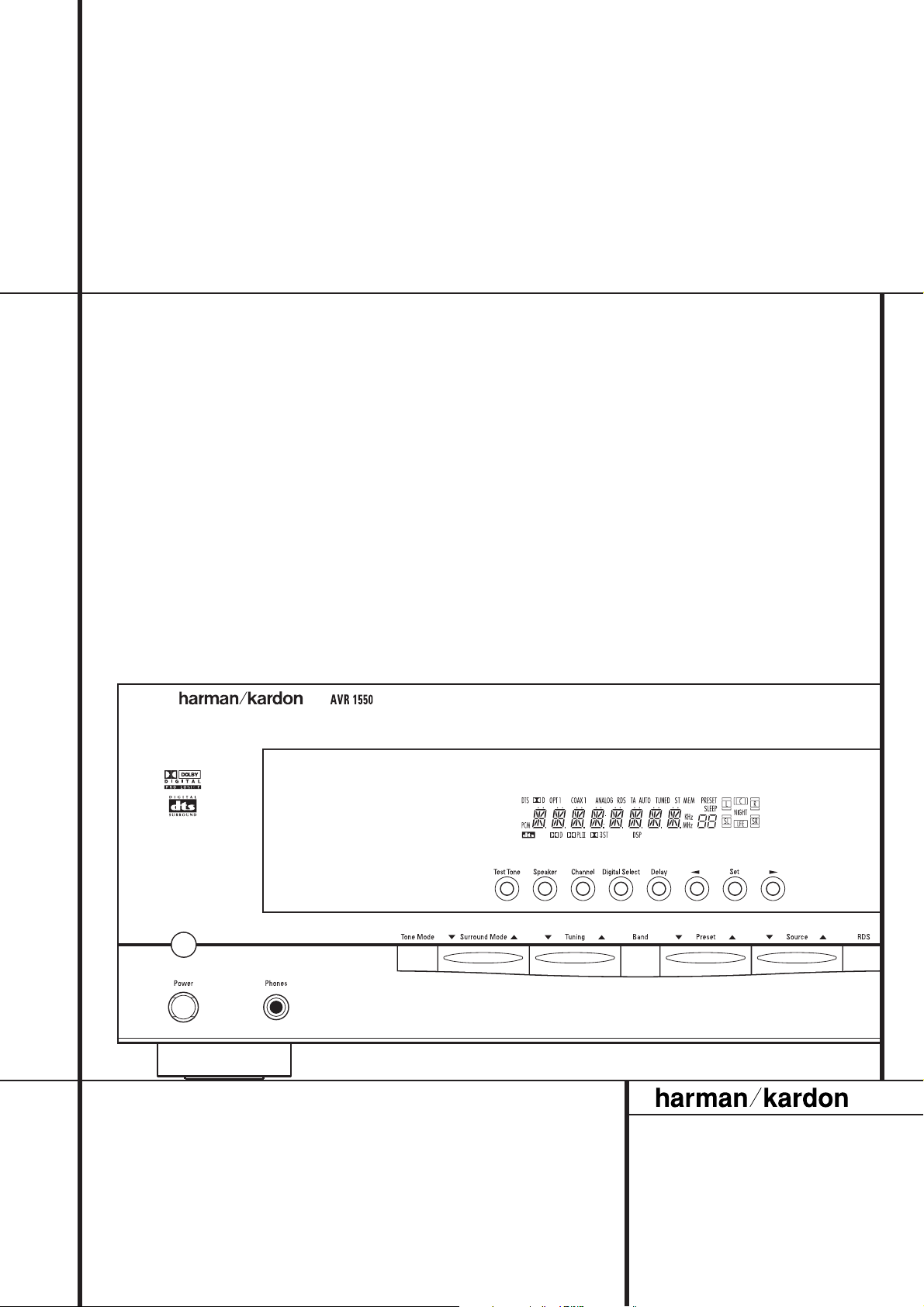
Front Panel Controls
1
2
3
Main Power Switch
1
System Power Control
2
Power Indicator
3
Headphone Jack
4
Remote Sensor Window
5
Tone Mode
6
Surround Mode Selector
7
Tuning
8
4
5
^#
$
6
7
Tuner Band Selector
9
Preset Stations Selector
)
Input Source Selector
!
RDS Select Button
@
Channel Select Button
#
Speaker Select Button
$
Video 3 input jacks
%
Test Tone Selector
^
8
*
9
)
!
Ó
Ô
&
(
@
Selector Buttons
&
Main Information Display
*
Volume Control
(
Set Button
Ó
Digital Input Selector
Ô
Delay
%
1
Main Power Switch: Press this button to
apply power to the AVR 1550. When the switch
is pressed in, the unit is placed in a Standby
mode, as indicated by the orange LED
rounding the System Power Control
button MUST be pressed in to operate the unit.
To turn the unit off completely and prevent the
use of the remote control, this switch should be
pressed until it pops out from the front panel
so that the word “OFF” may be read at the top
of the switch.
NOTE:This switch is normally left in the “ON”
position.
3
2
sur-
. This
2
System Power Control:When the Main
Power Switch
turn on the AVR 1550; press it again to turn the
unit off (to Standby). Note that the Power
Indicator surrounding the switch
green when the unit is on.
3
Power Indicator: This LED will be illumi-
nated in orange when the unit is in the Standby
mode to signal that the unit is ready to be
turned on. When the unit is in operation, the
indicator will turn green.
4
Headphone Jack: This jack may be used to
listen to the AVR 1550’s output through a pair
of headphones. Be certain that the headphones
have a standard 6.3 mm stereo phone plug.
Note that the speakers will automatically be
turned off when the headphones are connected.
1
is “ON,”press this button to
3
will turn
5
Remote Sensor Window:The sensor
behind this window receives infrared signals
from the remote control. Aim the remote at this
area and do not block or cover it unless an
external remote sensor is installed.
6
Tone Mode: Pressing this button activates
the menu for setting the Bass and Treble
controls.
FRONT PANEL CONTROLS 5
Page 6

Front Panel Controls
7
Surround Mode Selector: Press this but-
ton to change the surround mode by scrolling
through the list of available modes. Note that
Dolby Digital and DTS modes can be selected
only when a digital input is used (See page 20
for more information about surround modes.)
8
Tuning Selector: Press the left side of the
button to tune lower frequency stations and the
right side of the button to tune higher frequency
stations.When a station with a strong signal is
reached, the TUNED indicator
in the Main Information Display
(see page 24 for more information on tuning
stations).
9
Tuner Band Selector: Pressing this button
will automatically switch the AVR to the Tuner
mode. Pressing it again will switch between the
AM and FM frequency bands, holding it pressed
for some seconds will switch between stereo
and mono receiving and between automatic and
manual tuning mode (See page 24 for more
information on the tuner).
)
Preset Stations Selector: Press this but-
ton to scroll up or down through the list of stations that have been entered into the preset
memory. (See page 24 for more information on
tuner programming.)
!
Input Source Selector: Press this button
to change the input by scrolling through the list
of input sources.
@ RDS Select Button: Press this button to dis-
play the various messages that are part of the
RDS data system of the AVR 1550’s tuner. (See
page 24 for more information on RDS).
L
will illuminate
*
#
Channel Select Button: Press this button
to begin the process of trimming the channel
output levels using an external audio source.
(For more information on output level trim
adjustment, see page 23.)
$
Speaker Select Button: Press this button
to begin the process of selecting the speaker
positions that are used in your listening room.
(See page 14 for more information on setup and
configuration.)
%
Video 3 Input Jacks: These audio/video
jacks may be used for temporary connection to
video games or portable audio/video products
such as camcorders and portable audio players.
^
Test Tone Selector: Press this button to
begin the process of adjusting the channel output levels using the internal test tone as a reference. (For more information on output level
adjustment, see page 17.)
&
Selector Buttons: When you are establish-
ing the AVR 1550’s configuration settings,use
these buttons to select from the choices available,
as shown in the Main Information Display
*
Main Information Display: This display
delivers messages and status indications to help
you operate the receiver. (See pages 7–8 for a
complete explanation of the Information
Display.)
*
(
Volume Control:Turn this knob clockwise
to increase the volume, counterclockwise to
decrease the volume. If the AVR is muted,
adjusting volume control will automatically
release the unit from the silenced condition.
Ó
Set Button: When making choices during
the setup and configuration process,press this
button to enter the desired setting as shown in
the Main Information Display
AVR 1550’s memory. The set button may also be
used to change the display brightness.
(See page 23.)
Ô
Digital Input Selector: When playing a
source that has a digital output, press this
button to select between the Optical
Coaxial
21-22 for more information on digital audio.)
sequence of steps required to enter delay time
settings. (See page 16 for more information on
delay times.)
.
Digital inputs. (See pages
Delay: Press this button to begin the
*
into the
and
6 FRONT PANEL CONTROLS
Page 7
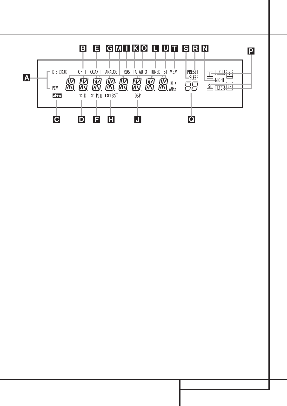
Front Panel Information Display
A
Bitstream Indicators
B
Optical Source Indicators
C
DTS Mode Indicator
D
Dolby Digital Indicator
E
Coaxial Digital Input Indicators
F
Dolby Pro Logic II Indicator
G
Analog Input Indicator
A
Bitstream™ Indicators:When the input is a
digital source, one of these indicators will light to
display the specific type of signal in use.
B
Optical Source Indicators: These indica-
tors light to show when a Optical Digital Input
has been selected.
C
DTS Mode Indicator: This indicator illumi-
nates when the DTS mode is selected.
D
Dolby Digital Indicator: This indicator
illuminates when Dolby Digital mode is selected.
E
Coaxial Digital Input Indicators: These
indicators light to show when a Coaxial Digital
Input has been selected.
F
Dolby Pro LogicII Indicator: This indica-
tor lights when the Dolby Pro Logic II mode has
been selected.
G
Analog Input Indicator: This indicator lights
when an analog input source has been selected.
H
Dolby 3 Stereo Indicator: This indicator
lights when the Dolby 3 Stereo Mode has been
selected. Only ST(Stereo) will light when
"Surround Off" has been selected. Then all
Surround Modes are turned off and the unit will
play in pure stereo mode.
I
RDS Indicator: This indicator illuminates
when the station tuned is transmitting RDS data.
H
Dolby 3 Stereo Indicator
I
RDS Indicator
J
DSP Mode Indicator
K
Traffic Program Indicator
L
Tuned Indicator
M
Main Information Display
N
Night Mode Indicator
J
DSP Mode Indicator: This indicator lights
when any of the surround modes created by
Digital Signal Processing, or DSP are in use.
These modes include Hall 1, Hall 2,Theater and
5 Channel Stereo.
K
Traffic Program Indicator:This indicator
illuminates if the RDS station tuned sometimes
transmits traffic information (see page 24 for
more information on RDS).
L
Tuned Indicator: This indicator illuminates
when a station is being received with sufficient signal strength to provide acceptable listening quality.
M
Main Information Display: This display
shows messages relating to the status, input
source, surround mode, tuner, volume level or
other aspects of unit’s operation.
N Night Mode Indicator:This indicator
lights when the AVR 1550 is in the Night mode,
which preserves the dynamic range of digital
program material at low volume levels.
O
Auto Indicator: This indicator illuminates
when the tuner’s Auto mode is in use.
P Speaker/Channel Input Indicators:These
indicators are multipurpose, indicating either the
speaker type selected for each channel or the
incoming data-signal configuration.The left,center, right, right surround and left surround speaker
indicators are composed of three boxes, while the
subwoofer is a single box. When the letters flash,
the digital input has been interrupted. (See page
18 and 27 for more information on the Channel
Indicators).
O
Auto Indicator
P
Speaker/Channel Input Indicators
Q
Preset Number/Sleep Timer
R
Preset Indicator
S
Sleep Indicator
T
Memory Indicator
U
Stereo Indicator
Q
Preset Number/Sleep Timer: When the
tuner is in use, these numbers indicate the specific preset memory location in use. (See page 24
for more information on preset stations.) When
the Sleep function is in use, these numbers show
how many minutes remain before the unit goes
into the Standby mode.
R
Preset Indicator: This indicator lights when
the tuner is in use to show that the Preset
Number/Sleep Timer
tion’s preset memory number. (See page 24 for
more information on tuner presets.)
S
Sleep Indicator: This indicator lights when
the Sleep function is in use.The numbers in the
Preset/Sleep Number Indicators will show the
minutes remaining before the AVR 1550 goes
into the Standby mode. (See page 19 for more
information on the Sleep function.)
T Memory Indicator: This indicator flashes
when entering presets and other information
into the tuner’s memory.
U
Stereo Indicator: This indicator illuminates
when an FM station is being tuned in stereo.
Q
is showing the sta-
FRONT PANEL INFORMATION DISPLAY 7
Page 8
fi
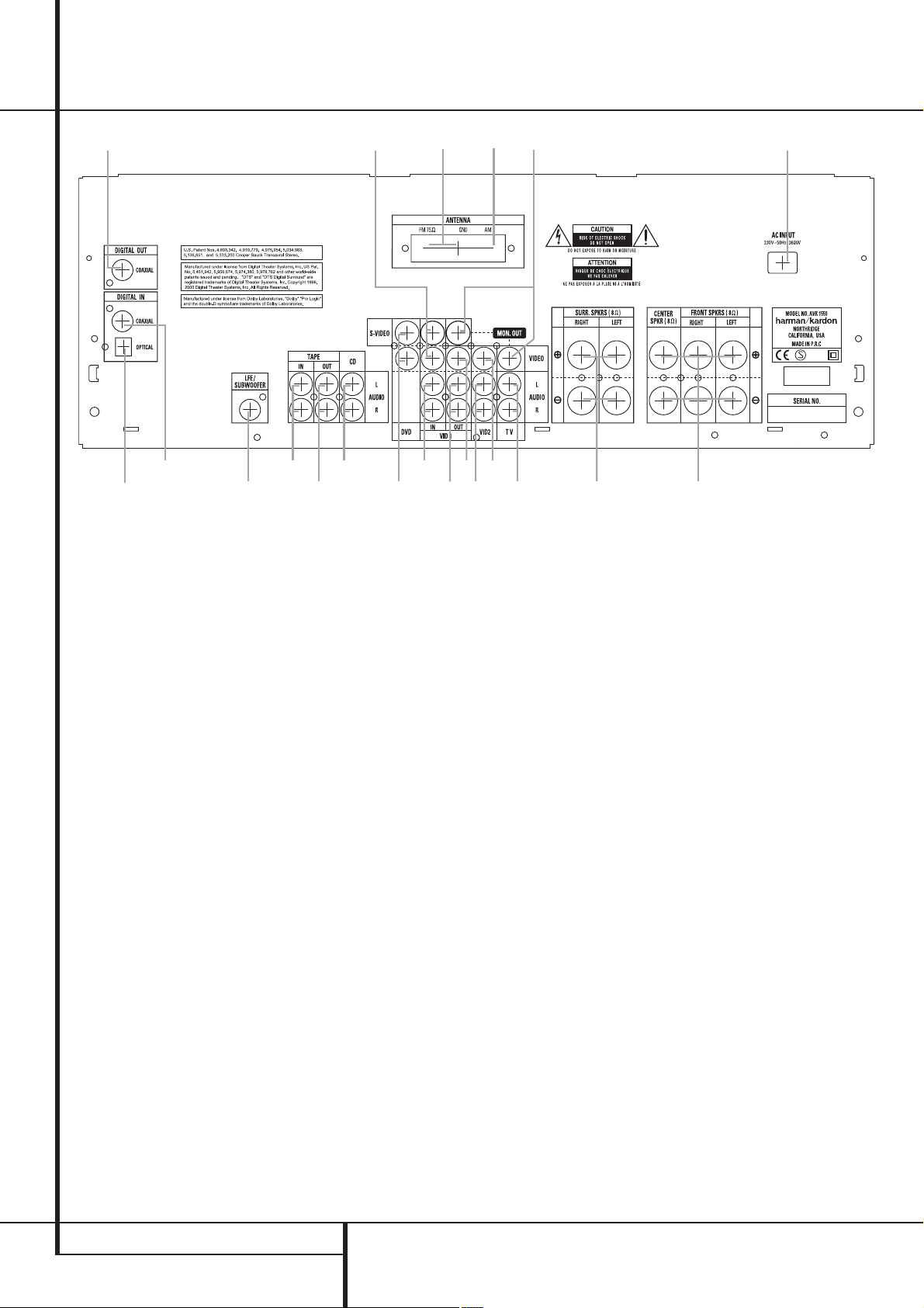
Rear Panel Connections
ª
‚
fl
Tape Inputs
Tape Outputs
Video 1 Audio Inputs
AM Antenna
Video 1 Audio Outputs
Video 2 Audio Inputs
FM Antenna
⁄
¡
™
a
•
CD Inputs
Coaxial Digital Audio Outputs
Coaxial Digital Inputs
Subwoofer Output
Video Monitor Outputs
Front/Center Speaker Outputs
Surround Speaker Outputs
¶
£
°
∞
·
§
¢
b
¤
›
‹
TV Audio Inputs
Optical Digital Inputs
AC Power Cord
DVD Video Inputs
Video 1 Video Outputs
Video 1 Video Inputs
Video 2 Video Inputs
‡
Tape Inputs: Connect these jacks to the
PLAY/OUT jacks of an audio recorder.
Tape Outputs: Connect these jacks to the
RECORD/INPUT jacks of an audio recorder.
Video 1 Audio Inputs: Connect these jacks
to the PLAY/OUT audio jacks on a VCR or other
video source.
AM Antenna:Connect theAM loop antenna
supplied with the receiver to theseterminals.If an
external AMantenna is used,make connections to
the AM and GND terminals in accordance with
the instructions supplied with the antenna.
Video 1 Audio Outputs: Connect these
jacks to the RECORD/INPUT audio jacks on
a VCR or any other Audio recorder.
Video 2 Audio Inputs: Connect these jacks
to the PLAY/OUT audio jacks on a VCR or other
video source.
FM Antenna: Connect the supplied indoor or
an optional external FM antenna to this terminal.
CD Inputs: Connect these jacks to the ana-
log output of a compact disc player or CD
changer.
CoaxialDigital Audio Outputs: Connect
this jack to the matching digital input connector
on a digital recorder such as a CD-R or MiniDisc
recorder.
Coaxial Digital Inputs: Connect the coax
digital output from a DVD player. Do not connect
the RF digital output of an LD player to these
jacks.
Subwoofer Output: Connect this jack to
the line-level input of a powered subwoofer. If
an external subwoofer amplifier is used, connect
this jack to the subwoofer amplifier input.
Video Monitor Outputs: Connect these
jacks to the composite and/or S-Video input of a
TV monitor or video projector to view the output
of any video source selected by the receiver’s
video switcher.
Front/Center Speaker Outputs: Connect
these outputs to the matching + or – terminals
on your front/center speakers.When making
speaker connections,always make certain to
maintain correct polarity by connecting the red
(+) terminals on the AVR 1550 to the red (+)
terminals on the speaker and the black (–) terminals on the AVR 1550 to the black (–) terminals on the speakers.(See page 11 for more
information on speaker polarity.)
Surround Speaker Outputs: Connect
these outputs to the matching + or – terminals
on your left and right surround speakers.When
making speaker connections always make certain to maintain correct polarity by connecting
the red (+) terminals on the AVR 1550 to the
red (+) terminals on the speakers and the black
(–) terminals on the AVR 1550 to the black (–)
terminals on the speakers.See page 11 for more
information on speaker polarity.
TV Audio Inputs: Connect these jacks to
the Audio Out jacks on a TV or other video
source.
Optical Digital Inputs: Connect the opti-
cal digital output from a DVD player, HDTV
receiver, LD player,MD player or CD player to
these jacks.The signal may be either a Dolby
Digital signal, a DTS signal or a standard PCM
digital source.
AC Power Cord: Connect the AC plug to an
unswitched AC wall output.
DVD Video Inputs: Connect these jacks to
the composite or S-Video output jacks on a DVD
player or other video source.
Video 1 Video Outputs: Connect these
jacks to the RECORD/INPUT composite or
S-Video jack on a VCR.
Video 1 Video Inputs: Connect these jacks
to the PLAY/OUT composite or S-Video jacks on
a VCR or other video source.
Video 2 Video Inputs: Connect these jacks
to the PLAY/OUT composite jacks on a second
VCR or other video source.
8 REAR PANEL CONNECTIONS
Page 9
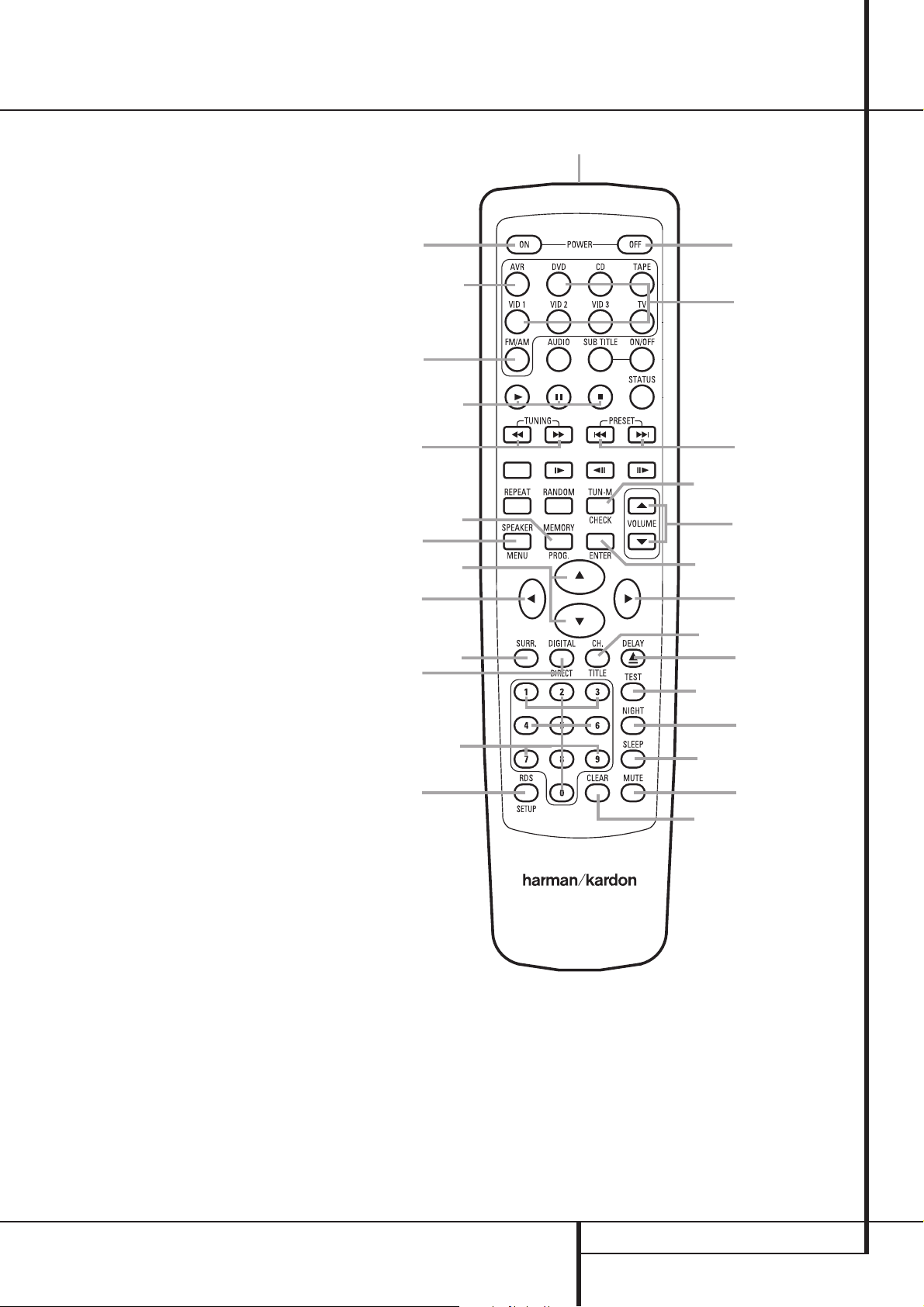
Remote Control Functions
0
Power On Button
1
IR Transmitter Window
2
Mute
3
Power Off Button
4
Input Selectors
5
AVR Selector
6
AM/FM Tuner Select
7
Test Button
8
Sleep Button
9
Surround Mode Selector
A
Night Mode
B
Channel Select Button
⁄/¤
C
D
E
F
G
H
I
J
K
L
M
N
O
P
Q
Buttons
‹
Button
Enter Button
Digital Select/Direct Button
Numeric Keys
Tuner Mode
Volume Up/Down
Tuning Up/Down
Speaker Select
Transport Controls
›
Button
RDS Select Button
Preset Up/Down
Clear Button
Memory Button
Delay
a
g
t
u
n
f
v
`
m
b
d
e
y
r
s
o
w
NOTE:The function names shown here are each
button’s feature when used with the AVR. Most
buttons have additional functions when used
with other Harman Kardon devices.
See page 26 for a list of these functions.
IMPORTANT NOTE: The AVR 1550’s remote is
shipped from the factory to operate the
AVR 1550 and most Harman Kardon CD or DVD
players and cassette decks.
Before using the remote, it is important to
remember to press the Input Selector button
4
that corresponds to the unit you wish to
operate.
It is also important to remember that many of
the buttons on the remote take on different
functions, depending on the product selected
using the Input Selectors.The descriptions
shown here primarily detail the functions of the
remote when it is used to operate the
AVR 1550. (See page 26 for information about
alternate functions for the remote’s buttons.)
j
p
q
x
AVR 1550
0
Power On Button: Press this button to
turn on the power.
1
IR Transmitter Window: Point this
window towards the AVR 1550 when pressing
buttons on the remote to make certain that
infrared commands are properly received.
2
Mute: Press this button to momentarily
silence the AVR 1550 or TV set being controlled,
depending on which device has been selected.
l
7
k
8
c
z
3
Power Off Button: Press this button to
place the AVR 1550 in the Standby mode.
4
Input Selectors: Pressing one of these
buttons will perform three actions at the same
time. First,if the AVR is not turned on, this will
power up the unit. Next, it will select the source
shown on the button as the input to the AVR.
Finally, it will change the remote control so that
it controls the compatible Harman Kardon product selected. After pressing one of these buttons
you must press the AVR Selector button
5
REMOTE CONTROL FUNCTIONS 9
Page 10

Remote Control Functions
90
min80min70min60min50min
40
min
30
min20min10min
OFF
again to operate the AVR’s functions with the
remote.
5
AVR Selector: Pressing this button will
switch the remote so that it will operate the AVR’s
functions. If the AVR is in the Standby mode,it will
also turn the AVR on.
6
AM/FM Tuner Select: Press this button to
select the AVR’s tuner as the listening choice.
Pressing this button when the tuner is in use will
select between the AM and FM bands.
7
Test Tone: Press this button to begin the
sequence used to calibrate the AVR 1550’s output
levels. (See page 17 for more information on
calibrating the AVR 1550.)
8
Sleep Button: Press this button to place
the unit in the Sleep mode.After the time shown
in the display, the AVR 1550 will automatically
go into the Standby mode. Each press of the
button changes the time until turn-off in the following order:
Hold the button pressed for two seconds to turn
off the Sleep mode setting.
Note that this button is also used to change
channels on your TV,VCR and SAT receiver when
selected.
9
Surround Mode Selector: Press this
button to begin the process of changing
the surround mode. After the button has
been pressed, use the
⁄/¤
buttons Cto
select the desired surround mode (See page 21
for more information).
A
Night Mode: Press this button to activate
the Night mode.This mode is available only with
Dolby Digital encoded digital sources, and it
preserves dialog (center channel) intelligibilty at
low volume levels (See page 22 for more
information).
B
Channel Select Button: This button is
used to start the process of setting the AVR 1550’s
output levels with an external source. Once this
button is pressed, use the
⁄/¤
buttonsCto
select the channel being adjusted, then press the
Enter button
E
, followed by the
⁄/¤
buttons
again, to change the level setting. (See page 23 for
more information.)
⁄/¤
C
Buttons: These are multi-purpose
buttons. They will be used most frequently to select
a surround mode.These buttons are also used to
increase or decrease output levels when configuring the unit, to select speaker configuration or
to select the digital inputs.They are also used to
enter delay time settings after the Delay button
has been pressed.
D‹Button: This button does not have a
function with the AVR 1550. When a DVD player
or TV is selected, it may be used to navigate the
menus of those devices.
E
Enter Button: This button is used to enter
settings into the AVR 1550’s memory. It is also
used in the setup procedures for delay time,
speaker configuration and channel output level
adjustment.
F
Digital Select/Direct: Press this button to
assign one of the digital inputs
to a
source. (See page 22 for more information on
using digital inputs).
In Tuner-mode, press this button when the tuner
is in use to start the sequence for direct entry of
a station’s frequency. After pressing the button
simply press the proper Numeric Keys
G
to
select a station (See page 24 for more information on the tuner).
G
Numeric Keys: These buttons serve as a
ten-button numeric keypad to enter tuner preset
positions.They are also used to select channel
numbers when TV, VCR or Sat receiver has
been selected on the remote, or to select track
numbers on a compatible Harman Kardon CD,
DVD or LD player.
H
Tuner Mode: Press this button when the
tuner is in use to select between automatic tuning and manual tuning. When the button is
pressed so that the AUTO indicator
out, pressing the Tuning buttons
O
goes
J8will
move the frequency up or down in single-step
increments.When the FM band is in use and the
AUTO indicator
O
is on, pressing this button
will change to monaural reception making even
week stations audible. (See page 24 for more
information.)
I
Volume Up/Down: Press these buttons to
raise or lower the system volume.
J
Tuning Up/Down:When the tuner is in use,
these buttons will tune up or down through the
selected frequency band. If the Tuner Mode but-
ton
H
has been pressed or the Band button
@
on the front panel was held pressed so that
the AUTO indicator
O
is illuminated, pressing
either of the buttons will cause the tuner to seek
the next station with acceptable signal strength
for quality reception.When the AUTO indicator
O
is NOT illuminated, pressing these buttons will
tune stations in single-step increments.
(See page 24 for more information.)
K
Speaker Select: Press this button to
begin the process of configuring the
AVR 1550’s Bass Management System for use
with the type of speakers used in your system.
Once the button has been pressed, use the
⁄/¤
buttons Cto select the channel you
wish to set up. Press the Enter button
E
and
then select the speaker type (see page 14 for
more information.)
L
Transport Buttons: These buttons do not
have any functions for the AVR, but they may be
used for the forward/reverse play operation of a
wide variety of compatible Harman Kardon CD
or DVD players, and audio or video- cassette
recorders.
M›Button: This button does not have a
function with the AVR 1550. When a compatible
Harman Kardon DVD player or TV is selected, it
may be used to navigate the menus of those
devices.
N
RDS Select Button: Press this button to
display the various messages that are part of the
RDS data system of the AVR 1550’s tuner.
(See page 24 for more information on RDS).
O
Preset Up/Down:When the tuner is in use,
press these buttons to scroll through the stations
programmed into the AVR 1550’s memory.
P
Clear Button: Press this button to clear
incorrect entries when using the remote to
directly enter a radio station’s frequency.
Q
Memory Button: Press this button to enter
a radio station into the AVR 1550’s preset
memory.After pressing the button the MEMORY
indicator
T
will flash; you then have five sec-
onds to enter a preset memory location using
the Numeric Keys
G
. (See page 23 for more
information.)
Delay/Prev Ch.: Press this button to begin
the process for setting the delay times used by
the AVR 1550 when processing surround sound.
After pressing this button, the delay times are
entered by pressing the Enter button
then using the
⁄/¤
buttons Cto change the
E
and
setting. Press the Enter button again to complete the process. (See page 16 for more information.)
10 REMOTE CONTROL FUNCTIONS
Page 11

Installation and Connections
After unpacking the unit, and placing it on a solid
surface capable of supporting its weight, you will
need to make the connections to your audio and
video equipment.
Audio Equipment Connections
We recommend that you use high-quality interconnect cables when making connections to
source equipment and recorders to preserve the
integrity of the signals.
When making connections to audio source
equipment or speakers it is always a good practice to unplug the unit from the AC wall outlet.
This prevents any possibility of accidentally sending audio or transient signals to the speakers
that may damage them.
Important Note : In order to clearly identify all
connectors and simplify nstallation, as per the
new EIA/CEA-863 standard, all connections are
colour coded as follows:
For Speakers and Audio In/Outputs: White (Left,
speakers front) and Red (Right, speakers front).
For Speakers:Green (Center), Blue (Left
Surround) and Grey (Right Surround).
For Audio Output: Purple (Subwoofer).
For Composite Video In/Outputs: Yellow.
For Digital Audio In/Outputs: Orange.
1. Connect the analog output of a CD player to
the CD inputs
NOTE:When the CD player has both fixed and
variable audio outputs it is best to use the fixed
output unless you find that the input to the
receiver is so low that the sound is noisy, or so
high that the signal is distorted.
2. Connect the analog Play/Out jacks of a cassette deck, MD,CD-R or other audio recorder to
the Tape Input jacks
Record/In jacks on the recorder to the Tape
Output jacks
3. Connect the digital output of any digital
device to the appropriate input connections on
the AVR 1550 rear panel. Note that the
Optical and Coaxial digital inputs
be used with a Dolby Digital or DTS source or
the output of a conventional CD, MD or LD
player’s PCM (S/P-DIF) output.
4. Connect the Coaxial Digital Outputs
the rear panel of the AVR to the matching digital
input connections on a CD-R or MiniDisc recorder.
5. Assemble the AM Loop Antenna supplied with
the unit as shown below. Connect it to the AM
and GND screw terminals
.
. Connect the analog
on the AVR 1550.
may
on
.
6. Connect the supplied FM antenna to the FM
(75 ohm) connection
. The FM antenna may
be an external roof antenna, an inside powered
or wire lead antenna or a connection from a
cable system. Note that if the antenna or connection uses 300-ohm twin-lead cable, you must
use a 300-ohm-to-75-ohm adapter to make the
connection.
7. Connect the front, center and surround speaker outputs
to the respective speakers.
To assure that all the audio signals are carried to
your speakers without loss of clarity or resolution, we suggest that you use high-quality
speaker cable.Many brands of cable are available and the choice of cable may be influenced
by the distance between your speakers and the
receiver, the type of speakers you use, personal
preferences and other factors.Your dealer or
installer is a valuable resource to consult in
selecting the proper cable.
Regardless of the brand of cable selected, we
recommend that you use a cable constructed of
fine, multistrand copper with an area greater
than 2 mm
Cable with an area of 1.5 mm
2
.
2
may be used for
short runs of less than 4 m.We do not recommend that you use cables with an area less than
2
1mm
due to the power loss and degradation in
performance that will occur.
Cables that are run inside walls should have the
appropriate markings to indicate listing with UL,
CSA or other appropriate testing agency standards. Questions about running cables inside
walls should be referred to your installer or a
licensed electrical contractor who is familiar with
the applicable local building codes in your area.
When connecting wires to the speakers,be certain to observe proper polarity. Remember to
connect the “negative” or “black” wire to the
same terminal on both the receiver and the
speaker. Similarly, the “positive” or “red” wire
should be connected to the same terminals on
the AVR 1550 and speaker.
NOTE:While most speaker manufacturers
adhere to an industry convention of using black
terminals for negative and red ones for positive,
some manufacturers may vary from this configuration.To assure proper phase and optimal performance, consult the identification plate on
your speaker or the speaker’s manual to verify
polarity. If you do not know the polarity of your
speaker, ask your dealer for advice before proceeding, or consult the speaker’s manufacturer.
We also recommend that the length of cable
used to connect speaker pairs be identical. For
example, use the same length piece of cable to
connect the front-left and front-right or surround-left and surround-right speakers,even if
the speakers have a different distance from the
AVR 1550.
8. Connections to a subwoofer are normally
made via a line level audio connection from the
Subwoofer Output
to the line-level input
of a subwoofer with a built-in amplifier. When a
passive subwoofer is used, the connection first
goes to a power amplifier, which will be connected to one or more subwoofer speakers.If
you are using a powered subwoofer that does
not have line-level input connections, follow the
instructions furnished with the speaker for connection information.
Note: Speaker sets with two front satellites and
a passive subwoofer must be connected to the
front speaker outputs
Subwoofer Output
only rather than to the
.
Video Equipment Connections
Video equipment is connected in the same manner as audio components.Again, the use of highquality interconnect cables is recommended to
preserve signal quality.To ensure best video performance S-Video sources should be connected
to the AVR 1550 only with their S-Video In/
Outputs, not with their composite video connectors too.
1. Connect a VCR’s audio and video Play/Out
jacks to the Video 1 or Video 2 In jacks
Video Record/In jacks on the VCR should be connected to the Video 1 jacks
AVR 1550.
2. Connect the analog audio and video outputs
of a satellite receiver, cable TV converter or television set or any other video source to the
Video 2
jacks.
3. Connect the video outputs of a DVD or laser
disc player to the DVD jacks
4. Connect the Video Monitor Out
the receiver to the composite and S-Video input
of your television monitor or video projector.
Video Connection Note:
• S-Video or Composite video signals may only
be viewed in their native formats and will not
be converted to the other format.
on the rear panel. The Audio and
(if not in use) or Video 3
.
on the
jacks on
%
INSTALLATION AND CONNECTIONS 11
Page 12

Installation and Connections
Black
Yellow
Red
Black
Red
Blue
Yellow
Green
White
Black
Yellow
Red
Rot
Schwarz
S-Video In
Schwarz
Rot
Blau
Gelb
S-Video In
S-Video Out
Rot
Schwarz
S-Video Out
SCART A/V Connections
For the connections described above your video
device needs RCA (cinch) connectors or/and
S-Video connectors for all Audio and Video
signals: Any normal video device (Not SVHS or
High 8) for only playback needs 3 RCA jacks,
VCRs for record and playback even 6 RCA jacks.
Any S-Video device (SVHS, High 8) needs 2 RCA
(Audio) and 1 S-Video jack (Video), if it’s a playback unit, or 4 RCA (Audio In/Out) and 2 S-Video
(Video In/Out) jacks, if it´s a recording VCR.
Many european video devices are equipped with
RCA (Cinch) or S-Video jacks only partially,not
with all audio and video in/outputs needed as
described above, but with a so called Scart or
Euro-AV connector (almost rectangular jack with
21 pins, see drawings on this page).
In that case the following Scart to Cinch adapters
or cables are needed:
• Units for playback, such as satellite receivers,
camcorders, DVD or LD players, need an adapter
from Scart to 3 RCA plugs, see fig.1 (normal
video devices) or from Scart to 2 RCA+1 SVideo plugs, see fig. 4 (S-Video devices).
• HiFi VCRs need an adapter from Scart to 6 RCA
plugs, see fig.2 (normal video), or from Scart to
4 Audio+2S-Video jacks, see fig.5 (S-Video
VCR). Read carefully the instruction attached to
the adapter to find which of the six plugs is
used for the record signal to the VCR (connect
with the AVR´s Out jacks) and for the playback
signal from the VCR (connect with the AVR´s In
jacks). Do not misconnect Audio and Video signals. Don´t hesitate to consult your dealer, if you
are uncertain.
• If you use only normal video devices the TV
monitor needs an adapter from 3 RCA plugs to
Scart (fig. 3) only. If also S-Video devices are
used an adapter from 2 RCA+1S-Video plugs to
Scart is needed additionally (fig. 6), connected
to the SCART input on your TV that is provided
for S-Video.
Note that only the video plugs (the "yellow"
cinch plug in fig. 3 and the S-Video plug in fig. 6)
must be connected to the TV Monitor Output
, and the volume on the TV must be reduced to
minimum.
Important Note for Adapter Cables:
If the cinch connectors of the adapter you’ll use
are labeled, connect the Audio and Video ”In”
plugs with the corresponding Audio and Video
”In” jacks on the AVR 1550 (and with a VCR connect the ”Out” plugs to the ”Out” jacks on the
AVR). Note that with some adapter types it may
be just turned around: If no signal is audible/ visible when the VCR is playing connect the “Out”
plugs to the ”In” jacks on the AVR and turned
around. If the adapter plugs are not labeled in
that way,pay attention to the signal flow direc-
12 INSTALLATION AND CONNECTIONS
SCART/Cinch-Adapter for
SCART/Cinch-Adapter for
record and playback;
Cinch/SCART-Adapter for
SCART/S-Video Adapter
SCART/S-Video Adapter
for record and playback;
SCART/S-Video Adapter
Figure 1:
playback;
signal flow:
SCART → Cinch
Figure 2:
signal flow:
SCART ↔ Cinch
Figure 3:
playback;
signal flow:
Cinch → SCART
Figure 4:
for playback;
signal flow:
SCART → Cinch
Figure 5:
signal flow:
SCART ↔ Cinch
Figure 6:
for playback;
signal flow:
Cinch → SCART
Black
Yellow
Red
Red
Black
S-Video Out
1
Also other colours possible, e.g. brown and grey.
tions as shown in the diagrams above and in the
instruction attached to the adapter. If uncertain,
don’t hesitate to consult your dealer.
Important Notes for S-Video connections:
1. Only the S-Video In/Out of S-Video devices
must be connected to the AVR, NOT both, normal video and S-Video In/Outputs (except the TV,
see item 2).
2. Like most common AV units the AVR 1550
does not convert the Video signal to S-Video or
vice versa. Thus both connections must be made
from the AVR 1550 to the TV if both, Video and
S-Video sources, are used, and the appropriate
input on the TV must be selected.
Black
Yellow
Red
Black
Red
1
Blue
Yellow
1
Green
White
Red
Black
S-Video In
Black
Red
1
Blue
Yellow
S-Video In
S-Video Out
Important Note for the Use of
SCART-Cinch Adapters:
When video sources are connected to the TV
directly with a SCART cable, specific control signals apart from Audio/Video signals will be fed
to the TV.These specific signals are:With all
video sources, the signal for automatic input
selection that switches the TV automatically to
the appropriate input as soon as the video
source is started. And with DVD players, the signals automatically turning the TV to 4:3/16:9
format (with 16:9 TVs or 4:3 TVs with 16:9
capability) and turning the RGB video decoder of
the TV on or off, depending on the DVD player´s
setting. With any adapter cable, these control
signals will be lost and the appropriate setting
of the TV must be made manually.
Page 13

Installation and Connections
Right Front
Speaker
Left Front
Speaker
No more than
60cm
Center Front Speaker
Speaker Selection
No matter which type or brand of speakers is
used, the same model or brand of speaker
should be used at least for the front-left, center
and front-right speakers.This creates a seamless
front soundstage and eliminates the possibility
of distracting sonic disturbances that occur when
a sound moves across mismatched front-channel
speakers.
Speaker Placement
The placement of speakers in a multichannel
home-theater system can have a noticeable
impact on the quality of sound reproduced.
Depending on the type of center-channel
speaker in use and your viewing device,place
the center speaker either directly above or below
your TV, or in the center behind a perforated
front-projection screen.
Once the center-channel speaker is installed,
position the left-front and right-front speakers so
that they are as far away from one another as
the center-channel speaker is from the preferred
listening position. Ideally, the front-channel
speakers should be placed so that their tweeters
are no more than 60cm above or below the
tweeter in the center-channel speaker.
They should also be at least 0.5 meter from your
TV set unless the speakers are magnetically
shielded to avoid colourings on the TV screen.
Note that most speakers are not shielded, even
with complete surround sets only the Center
speaker may be.
Depending on the specifics of your room
acoustics and the type of speakers in use,you
may find that imaging is improved by moving the
front-left and front-right speakers slightly
forward of the center-channel speaker. If
possible, adjust all front loudspeakers so that
they are aimed at ear height when you are
seated in the listening position.
Using these guidelines, you’ll find that it takes
some experimentation to find the correct
location for the front speakers in your particular
installation. Don’t be afraid to move things
around until the system sounds correct. Optimize
your speakers so that audio transitions across
the front of the room sound smooth.
Surround speakers should be placed on the side
walls of the room, at or slightly behind the
listening position. The center of the speaker
should face you.
If side-wall mounting is not practical, the
speakers may be placed on a rear wall, behind
the listening position. The speakers should be no
more than two meters behind the rear of the
seating area.
Subwoofers produce largely nondirectional
sound, so they may be placed almost anywhere
in a room. Actual placement should be based on
room size and shape and the type of subwoofer
used. One method of finding the optimal
location for a subwoofer is to begin by placing it
in the front of the room, about 15cm from a
wall, or near the front corner of the room.
Another method is to temporarily place the
subwoofer in the spot where you will normally
sit, and then walk around the room until you
find a spot where the subwoofer sounds best.
Place the subwoofer in that spot. You should
also follow the instructions of the subwoofer’s
manufacturer, or you may wish to experiment
with the best location for a subwoofer in your
listening room.
A) Front Channel Speaker Installation with
Direct-View TV Sets or Rear-Screen Projectors
TV or Projection Screen
Left Front
Speaker
No more than 2m
speakers are used
when rear-mounted
Center Front
Speaker
Optional Rear-Wall Mounting
Right Front
Speaker
B) The distance between the left and right
speakers should be equal to the distance from
the seating position to the viewing screen.
You may also experiment with placing the left
and right speakers slightly forward of the center
speaker.
INSTALLATION AND CONNECTIONS 13
Page 14

System Configuration
Once the speakers have been placed in the
room and connected, the remaining steps are to
program the system configuration memories.
With the AVR 1550 two kind of memories are
used, those associated individually with the
input selected, e.g.surround modes, and others
working independently from any input selected
like speaker output levels, or delay times used
by the surround sound processor.
First Turn On
You are now ready to power up the AVR 1550 to
begin these final adjustments.
1. Plug the Power Cable
switched AC outlet.
2. Press the Main Power Switch
latches and the word “OFF” on the top of the
switch disappears inside the front panel. Note
that the Power Indicator
indicating that the unit is in the Standby mode.
3. Remove the protective plastic film from the
front-panel lens. If left in place, the film may
affect the performance of your remote control.
4. Install the three supplied AAA batteries in the
remote as shown. Be certain to follow the (+)
and (–) polarity indicators that are on the
bottom of the battery compartment.
5.Turn the AVR 1550 on either by pressing the
System Power Control
Source Selector
the remote by pressing the AVR Selector
or any of the Input Selectors
remote.The Power Indicator
to confirm that the unit is on, and the Main
Information Display
into an un-
1
3
will turn orange,
2
or the Input
!
on the front panel, or via
46
3
will turn green
*
will also light up.
in until it
5
on the
Settings to be Made With Each
Input Used
The AVR 1550 features an advanced memory
system that enables you to establish different
settings for the speaker configuration, digital
input and surround mode for each input source.
This flexibility enables you to custom tailor the
way in which you listen to each source and have
the AVR 1550 memorize them. This means, for
example, that you may associate different surround modes and analog or digital inputs with
different sources, or set different speaker configurations with the resultant changes to the bass
management system or the use of the Center
speaker. Once these settings are made, they will
automatically be recalled whenever you select
an input.
The default settings for the AVR 1550, as it is
shipped from the factory, have all inputs set for
an analog source (except for the DVD input,
which has the Coaxial Digital Input 1
the default), with stereo as the surround mode,
the front left and right speakers set to “large”
(with surround modes other speakers to
”small”), and a subwoofer connected. Before
using the unit, you will probably want to change
these settings for most inputs so that they are
properly configured to reflect the use of digital
or analog inputs, the type of speakers installed
and the surround mode associated with the
input. Remember, since the AVR 1550’s memory
system keeps the settings for each input separate from the other inputs, you will need to make
these adjustments for each input used. However,
once they are made, further adjustment is only
required when system components are changed.
To make this process as quick and as easy as
possible, we suggest that with each of these settings to be made you step through each input.
Once you have completed the settings for the
first input, many settings may be duplicated for
the remaining inputs.
The items that follow will describe the individual
settings required for each input.
as
Input Setup
The first step in configuring the AVR 1550 is to
select an input. This may be done by pressing
the front panel Input Source Selector
until the desired input’s name appears momentarily in the Main Information Display
The input may also be selected by pressing
the appropriate Input Selector on the
remote control
The second step is to associate one of the digital
inputs with the selected input source (if this is
needed, otherwise the selected analog input will
remain). Press the Digital Input Select button
ÔFon the front panel or the remote.Within
five seconds, make your input selection using the
Selector buttons on the front panel
⁄/¤ buttons
desired digital or analog input is shown in the
Main Information Display
Enter button
assignment.
After the setting has been made with one input,
repeat as described above with all inputs in use.
The digital input associated with the input
selected can also be changed at any time later
and the AVR 1550´s memory system will keep
the settings until they are changed again.
Speaker Setup
This setup tells the AVR 1550 which type of
speakers are in use.This is important as it
adjusts the settings that determine which
speakers receive low frequency (bass) information and whether a Center speaker should be
used or not, separately for each input used.
For each of these settings use the LARGE
setting if the speakers for a particular position
are traditional full-range loudspeakers that are
capable of reproducing sounds below 100Hz.
Use the SMALL setting for smaller,
frequency-limited satellite speakers that do not
reproduce sounds below 100Hz. Note that
when “small” front (left and right) speakers are
used, a subwoofer is required to reproduce low
frequency sounds. If you are in doubt as to
which category describes your speakers,consult
the specifications in the speakers’ owner’s
manual, or ask your dealer. Remember that each
speaker setup that differs from the default
settings (see above) must be made individually
for each input in use.
It is best to select the Dolby Pro Logic II Movie
mode for speaker setup.Then with the currently
selected input all speaker settings will be copied
to other surround modes too (as far as possible)
and need not be repeated with any other mode.
46
.
C
on the remote until the
M
E
to enter the new digital input
!
M
.
&
or the
. Then press the
14 SYSTEM CONFIGURATION
Page 15

System Configuration
With the AVR 1550 turned on, follow these
steps to configure the speakers:
1. Put the AVR 1550 in the Dolby Pro Logic II
Movie mode by pressing the Surround Mode
Selector button
then the
7
on the front or 9and
⁄/¤
buttons Con the remote, until
DOLBY PRO LOGIC II MOVIE
appears in the Main Information Display
M
and the PRO LOGIC II indicator Flights.
2. Press the Speaker button
K$on the
remote or front panel. The words FNT
SPKRwill appear in the Main Information
Display
M
.
3. Press the Enter button
control, or the Set button on the front
4. Press the
⁄/¤
the Selector buttons
E
on the remote
Ó
.
buttons Con the remote or
&
on the front panel
until either F-LARGE or F-SMALL
appears, matching the type of speakers you have
at the left-front and right-front positions, as
described by the definitions shown in preceding
section.
When SMALL is selected, low frequency front
channel sounds will be sent only to the subwoofer
output. Note that if you choose this option and
there is no subwoofer connected, you will not
hear any low frequency sounds from the front
channels.This setting is not available with stereo
mode to ensure purest sound by bypassing the
crossovers of the DSP´s.
When LARGE is selected, a full-range output
will be sent to the front left and front right outputs. Depending on the subwoofer configuration
(see below), the front left and right bass information may also be directed to a subwoofer.
Important Note: When a speaker set with two
front satellites and a passive subwoofer is used,
connected to the front speaker outputs
,
the fronts must be set for LARGE.
5.When you have completed your selection for
the front channels, press the Enter button
E
on the remote control, or the Set button on the
front
Ó
, and then press the
⁄/¤
buttons
C
on the remote or the Selector buttons &on
the front panel to change the display to
CEN SPKR.
6. Press the Enter button
control, or the Set button on the front
again, and use the
remote, or the Selector buttons
E
⁄/¤
buttons Con the
on the remote
Ó
&
on the
front panel, to select the option that best
describes your system based on the Center
speaker definitions shown in preceding section.
When SMALL is selected, low frequency center channel sounds will be sent to the Fronts, if
they are set for LARGE and Sub is turned off.
When Sub is on, low frequency center channel
sounds will be sent to the subwoofer only.
When LARGE is selected, a full-range output
will be sent to the center speaker output, and
with analog and digital surround modes (except
with the Pro Logic II Music mode) NO center
channel signal will be sent to the subwoofer output.
When NONE is selected, no signal will be sent
to the center channel output. The receiver will
operate in a “phantom” center channel mode
and center channel information will be sent to
the left and right front channel outputs and its
bass will be sent to the subwoofer output too as
long as SUB L/R+LFE is selected in the SUBWOOFER line in this menu (see below). This
mode is needed if no Center speaker is used.
7. When you have completed your selection for
the center channel, press the Enter button
E
on the remote control, or the Set button on the
front
Ó
, and then press the
⁄/¤
buttons
C
on the remote or the Selector buttons &on
the front panel to change the display to
SUR SPKR.
8. Press the Enter button
control, or the Set button on the front
again, and then use the
remote or the Selector buttons
E
on the remote
⁄/¤
buttons Con the
&
Ó
on the front
panel to select the option that best describes
your system based on the Surround speaker
definitions shown in preceding section.
When SMALL is selected, with all digital surround modes low frequency surround channel
sounds will be sent to the Fronts,when Sub is
turned off,or to the subwoofer output when Sub
is on. With the analog surround modes the rear
bass feed depends on the mode selected and
the setting of the sub and front speakers.
When LARGE is selected, a full-range output
will be sent to the surround channel outputs
(with all analog and digital surround modes),
and, except with Hall and Theater modes, NO
surround channel bass will be sent to the subwoofer output.
When NONE is selected, surround sound
information will be split between the front-left
and front-right outputs. Note that for optimal
performance when no surround speakers are in
use, the Dolby 3 Stereo mode should be used
instead of Dolby Pro Logic.
9. When you have completed your selection for
the surround channel, press the Enter button
E
on the remote control, or the Set button on
the front
Ó
, and then press the
C
on the remote or the Selector buttons
⁄/¤
buttons
&
on the front panel to change the display to
S-W SPKR.
10. Press the Enter button
control, or the Set button on the front
then press the
⁄/¤
or the Selector buttons
E
on the remote
Ó
, and
buttons Con the remote
&
on the front panel
to select the option that best describes your
Subwoofer system.
The choices available for the subwoofer position
will depend on the settings for the other speakers, particularly the front left/right positions.
If the front left/right speakers are set to
SMALL, the subwoofer will automatically be
set to SUB, which is the “on” position.
If the front left/right speakers are set to
LARGE, three options are available:
• If no subwoofer is connected to the AVR 1550,
press the arrow buttons
C&so that
NONE appears in the display.When this
option is selected, all bass information will be
routed to the front left/right “main” speakers.
• If a subwoofer is connected to the AVR 1550,
you have the option to have the front left/right
“main” speakers reproduce bass frequencies at
all times, and have the subwoofer operate only
when the AVR 1550 is being used with a digital
source that contains a dedicated Low Frequency
Effects, or LFE soundtrack. This allows you to use
both your main and subwoofer speakers to take
advantage of the special bass created for certain
movies.To select that option press the arrow
buttons
C&so that SUB(LFE) appears
in the display.
• If a subwoofer is connected and you wish to
use it for bass reproduction in conjunction with
the main front left/right speakers,regardless of
the type of program source or surround mode
you are listening to, press the arrow buttons
C&so that L/R+LFE appears in the
display.When this option is selected, a “complete” feed will be sent to the front left/right
“main” speakers, and the subwoofer will receive
the front left and right bass frequencies under
the crossover frequency 80 Hz, additionally to
the LFE soundtrack (see above).
11. When all speaker selections have been made
for the input selected, Press the Enter button
E
on the remote control, or the Set button on
the front
Ó
twice or simply wait for three
seconds until the display returns to the normal
mode.
SYSTEM CONFIGURATION 15
Page 16
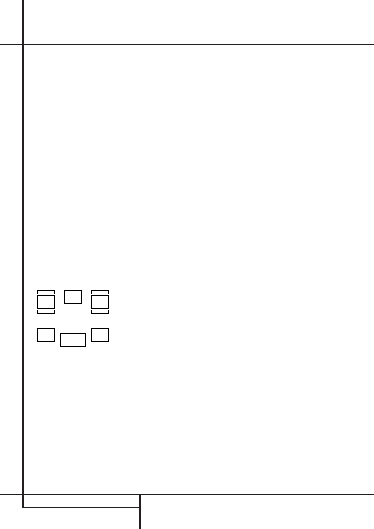
System Configuration
To assist in making these settings,the icons in
the Speaker/Channel Input Indicators
will change as the speaker type is selected at
each position. When only the inner icon box is lit,
the speaker is set for “small.” When the inner box
and the two outer boxes with circles inside them
are lit, the speaker is set for “large." When no
indicator appears at a speaker location, that
position is set for “none” or “no” speaker.
As an example, in the Figure below, the left front
and right front speakers are set for “large,” the
center, left surround and right surround speakers
are set for small, and a subwoofer is set.
After the speaker setting has been made with
one input, repeat as described above with all
inputs you will use. In most cases, the speaker
type will be the same and may be quickly entered
by entering the same data used for the original
input. But with some music sources you may
prefer to listen to your surround system without
using a Center speaker, particularily when a small
Center is in use with an audio performance not
matching perfectly with the main front speakers.
With these sources selected the Center speaker
will then be turned off automatically (enter
NONE for the Center setting), while its signal will
be fed to the left and right Fronts.
The speaker setting mode can also be changed at
any time later, and the AVR 1550´s memory
system will keep these settings for the input
selected, until they are changed again.
LR
SL SR
C
LFE
P
Surround Setup
Once the speaker setup has been completed, the
next setup step is to set the surround mode you
wish to use with each input. Since surround
modes are a matter of personal taste, feel free to
select any mode you wish – you may change it
later. The Surround Mode chart on page 20 may
help you select the mode best suited to the input
source selected. However, to make it easier to
establish the initial parameters for the AVR 1550,
it is best to select any Dolby Pro Logic II mode for
most analog inputs and Dolby Digital for inputs
connected to digital sources. In the case of inputs
such as a CD Player, Tape Deck or Tuner, you may
wish to set the mode to Stereo, if that is your
preferred listening mode for standard stereo
sources, where it is unlikely that sur
ed material will be used.
To set the surround mode you wish to use with
the input selected, press the Surround Mode
Selector button
⁄/¤ buttons
desired surround mode´s name appears in the
Main Information Display
Note that Dolby Digital and DTS will only appear
as choices when a digital input has been
selected.
After the surround mode setting has been made
with the current input, repeat the setting with all
inputs you will use.The surround mode can also
be changed at any time later, and the AVR 1550´s
memory system will keep the settings for the
input selected, until they are changed again.
7
on the front or 9and the
C
on the remote until the
M
round encod-
.
Making Settings independent of
selected Input
After the settings described above have been
made for all input sources in your system, the following settings, made with any input,will remain
in effect independent of the input selected.
Delay Settings
Only for the Dolby Digital or Dolby Pro Logic II
modes, you will need to adjust the delay time
setting. Note that the delay time is not
adjustable for any other modes.
Important Note: Once the delay time is set
with any input it will be effective with all other
inputs too. Moreover the surround delay time
setting must be made only for either the Dolby
Pro Logic II or the Dolby Digital mode.The other
setting will be set automatically.
Due to the different distances between the listening position for the front channel speakers
and the surround speakers,the amount of time it
takes for sound to reach your ears from the front
or surround speakers is different.You may compensate for this difference through the use of the
delay settings to adjust the timing for the specific
speaker placement and acoustic conditions in
your listening room or home theater.
The factory setting (see Surround Mode Chart
page 20) is appropriate for most rooms, but
some installations create an uncommon distance
between the front and surround speakers that
may cause the arrival of front channel sounds to
become disconnected from surround channel
sounds.
To resynchronize the front, center and surround
channels, follow these steps:
1. Measure the distance from the listening/
viewing position to the front speakers in
meters.
2. Measure the distance from the listening/
viewing position to the surround speakers.
3. Subtract the distance to the surround speakers
from the distance to the front speakers and
multiply the result by 3.
a.When setting the delay time for the Dolby
Digital surround modes, the optimal delay time
is the result of that subtraction. For example, if
the front speakers are 3 m away and the surround speakers are 1 m away, the optimal
delay time is figured as (3–1)x3=6. Thus,in
this example, the delay time for Dolby Digital
should be set at six milliseconds.
b.When setting the delay time for any Dolby Pro
Logic II mode, take the result of the calculation
above and add 15 to obtain the optimal delay
time.
For example,if the front speakers are 3 m
away and the surround speakers are 1 m away,
16 SYSTEM CONFIGURATION
Page 17

System Configuration
the optimal delay time is figured as
(3–1)x3+15=21. Thus, in this example, the
Pro Logic II delay should be set at twenty
milliseconds.
NOTE: The DTS, 5CH Stereo, Hall and Theater
modes use a fixed, nonadjustable delay time.
The Dolby Digital Mode also includes a separate
setting for the center channel delay mode, since
the discrete nature of these signals makes the
location of the center channel speaker more critical. To calculate the delay for the center channel,
measure the distance from the preferred listening
position in the center of the room to both the
center channel speaker and either the left or
right speaker.
If the distances are equal, no further adjustment
is required and the center delay should be left
zero. If the distance to the front speakers is
greater than the distance to the center speaker,
you may wish to reposition the speakers by
moving the front left and front right speakers
closer to the listening position or the center
speaker further away from the listening position.
If repositioning of the speakers is not possible,
adjust the center delay time, adding one millisecond of center channel delay for every 30 cm
closer to the listening position the center speaker
is than the front speakers.For example, if the
front left and front right speakers are each 3 m
from the listening position and the center channel speaker is 2.4 m away, the delay is figured as
300 cm –240 cm=60 cm, suggesting an optimal
center delay of 2 milliseconds.
To set the delay time,follow these steps:
1. To make the delay settings for the Dolby
Digital mode (this will include the Center delay
setting, and the surround delay for the
Pro Logic II mode will be set automatically), press
the Input Source Selector
4
on the remote and select any input now that
!
on the front or
is associated with a digital input and the Dolby
Digital surround mode.
2. Press the Delay button
on the remote
or front panel. The words S DELAY appear in
the Main Information Display
3. Press the Enter button
control, or the Set button on the front
4. Press the
the Selector buttons
⁄/¤
buttons Con the remote or
&
M
.
E
on the remote
Ó
.
on the front panel until
the desired rear delay time for the Dolby Digital
mode, calculated using the formula for Dolby
Digital above (item a.), appears in the display.
5. Press the Enter button
control, or the Set button on the front
E
on the remote
Ó
to
enter the setting into the AVR 1550’s memory.
6. Press the
⁄/¤
buttons Con the remote
once, so that C DELAYappears in the Main
Information Display
7. Press the Enter button
control, or the Set button on the front
8. Press the
⁄/¤
M
.
E
on the remote
Ó
.
buttons Con the remote
until the desired delay time for the center channel appears in the display.
9. Press the Enter button
control, or the Set button on the front
E
on the remote
Ó
to
enter the setting into the AVR 1550’s memory.
You have now completed the delay time settings
for all surround modes and inputs.
Night Mode Settings
The Night mode is a feature of Dolby Digital that
uses special processing to preserve the dynamic
range and full intelligibility of a movie sound
track while reducing the peak level.This prevents
abruptly loud transitions from disturbing others,
without reducing the sonic impact of a digital
source. Note that the Night mode is only available when the Dolby Digital surround mode is
selected.
To adjust the Night mode setting press the Input
Source Selector
!
on the front or 4on the
remote and select an input that is associated
with a digital input and the Dolby Digital surround mode.
Next press the Night button
A
on the remote.
When the button is pressed, the words D-R
(Dynamic Range) followed by the current setting
(MID, MAX,OFF) will appear in the Main
Information Display
Press the
⁄/¤
M
.
buttons Cwithin five seconds
to select the desired setting:
OFF: When OFF is shown in the display, the
Night mode will not function.
MID: When MID is shown in the display, a
mild compression will be applied.
MAX: When MAX is shown in the display, a
more severe compression algorithm will be
applied.
When you want to use the Night mode feature,
we recommend that you select the MID setting
as a starting point and change to the MAX
setting later, if desired.
When any Night mode is selected, the NIGHT
Mode Indicator
the selection press the Enter button
N
will illuminate.To confirm
E
on the
remote control, or the Set button on the front
Ó
or wait for some seconds until the display
returns to the normal mode.
Output Level Adjustment
Output level adjustment is a key part of the configuration process for any surround sound product. It is particularly important for a Dolby Digital
receiver such as the AVR 1550, as correct outputs
will ensure that you hear sound tracks with the
proper directionality and intensity.
NOTE: Listeners are often confused about the
operation of the surround channels.While some
assume that sound should always be coming
from each speaker, most of the time there will be
little or no sound in the surround channels.This
is because they are only used when a movie
director or sound mixer specifically places sound
there to create ambiance, a special effect or to
continue action from the front of the room to
the rear. When the output levels are properly set
it is normal for surround speakers to operate
only occasionally.Artificially increasing the
volume to the rear speakers may destroy the
illusion of an enveloping sound field that
duplicates the way you hear sound in a movie
theater or concert hall.
IMPORTANT NOTE: The output level can be
adjusted for each digital and analog surround
mode separately.This allows you to compensate
for level differences between speakers,that may
also vary with the surround mode selected, or to
increase or decrease the level of certain speakers
intentionally, depending on the surround mode
selected. Note that adjustments made for any
surround mode are effective with all inputs
associated with that surround mode.
Before beginning the output level adjustment
process, make certain that all speaker connections have been properly made.The system
volume should be turned down at first.
To adjust and calibrate the output levels, follow
these steps. For accurate calibration, it is a good
idea to make these adjustments while seated in
your favorite listening position. As the adjustment must be made for each surround mode, it is
best to select any input associated with any
Dolby Pro Logic II mode, make the adjustment for
that surround mode, then step through all inputs
you´re using (and thus through all surround
modes associated with the inputs) and repeat
the adjustment when any surround mode
appears that has not yet been adjusted.
1. Select any input associated with any
Dolby Pro Logic II surround mode by pressing the
Input Source Selector
Pro Logic II
F
2. Press the Test Tone button
!4until the
in the display light up.
7^on the
remote.The words TEST FLwill appear in the
Main Information Display
M
.
SYSTEM CONFIGURATION 17
Page 18

System Configuration
3. The test noise will immediately begin to circulate in the speakers in a clockwise rotation,
pausing at each position for two seconds.As the
test noise rotates the speaker positions FL,
CEN, FR, SR, SL(Front Left, Center, Front
Right, Surround Right, Surround Left) will be
shown in the Main Information Display
M
.
As an added assist, while the test noise is circulating, the proper channel position will also be
indicated in the Speaker/Channel Indicators
P
by a blinking letter within the correct channel. Turn up the volume now until you can hear
the noise clearly.
IMPORTANT NOTE: Because this test noise will
have a much lower level than normal music, the
volume must be lowered after the adjustment
for all channels is made, BEFORE you turn the
test tone off.
NOTE:This is a good time to verify that the
speakers have been properly connected.As the
test noise circulates, listen to make certain that
the sound comes from the speaker position
shown in the Main Information Display. If the
sound from a speaker location does NOT match
the position indicated in the display, turn the
AVR 1550 off using the Main Power Switch
1 and check the speaker wiring to make certain that each speaker is connected to the correct output terminal.
After checking for speaker placement, let the
test noise circulate again, and listen to see
which channels sound louder than the others.
Using the front left speaker as a reference,press
⁄/¤
the
buttons Con the remote to bring all
speakers to the same volume level. Note that
when one of the
⁄/¤
buttons is pushed, the
test noise circulation will pause on the channel
being adjusted to give you time to make the
adjustment.When you release the button, the circulation will resume after five seconds.
Continue to adjust the individual speakers until
they all have the same volume. Note that adjustments should be made with the
C
on the remote only, NOT the main volume
⁄/¤
buttons
controls.
NOTE: The subwoofer output level is not
adjustable using the test tone.To change the
subwoofer level, follow the steps for Output
Level Trim Adjustment on page 23.
When all channels have the same output level,
turn the Volume
(Idown to about -40dB,
otherwise the listening level may be too high as
soon as the source’s music starts to play. Afterwards press the Test Tone Selector
^
7
button again to turn the test tone off and complete the process.
IMPORTANT NOTE: The Output level adjustment made will be effective for the surround
mode currently selected, also when other inputs
are selected using the same surround mode.To
adjust the output level with all other surround
modes used, step through all inputs you´re using
by pressing the Source Selector buttons
!
on the front panel or the appropriate Input
Selectors
4
on the remote.When the indicator for any surround mode for which the level
adjustment has not yet been made lights in the
Main Information Display
M
, repeat the
level adjustment described above.This will also
allow you to compensate level differences
between speakers,that may be different with
each surround mode, or to increase or decrease
the level of certain speakers intentionally,
depending on the surround mode selected.
Once the settings outlined on the previous
pages have been made, the AVR 1550 is ready
for operation.While there are some additional
settings to be made, these are best done after
you have had an opportunity to listen to a variety of sources and different kinds of program
material. These advanced settings are described
on page 23 of this manual. In addition, any of
the settings made in the initial configuration of
the unit may be changed at any time.
As you add new or different sources or speakers,
or if you wish to change a setting to better
reflect your listening taste, simply follow the
instructions for changing the settings for that
parameter as shown above. Note that any settings changed at any time, will be stored in
memory in the AVR 1550, also if it´s turned off
completely, unless it will be reset (see page 27).
The settings will either depend on the input
(Speaker configuration, analog/digital input
selection, surround mode) or on the surround
mode selected (speaker output level), as
described on previous pages.
Having completed the setup and configuration
process for your AVR 1550, you are about to
experience the finest in music and home theater
listening. Enjoy!
18 SYSTEM CONFIGURATION
Page 19

Operation
90
min80min70min60min50min
40
min
30
min20min10min
OFF
Basic Operation
Once you have completed the setup and configuration of the AVR 1550, it is simple to operate
and enjoy.The following instructions should be
followed for you to maximize your enjoyment of
your new receiver:
Turning the AVR 1550 On or Off
• When using the AVR 1550 for the first time, you
must press the Main Power Switch
front panel to turn the unit on.This places the unit
in a Standby mode, as indicated by the orange
color of the Power Indicator
is in Standby,you may begin a listening session by
pressing the System Power Control
Source button
Selector
3
will turn green.This will turn the unit on and
!
on the front panel or the AVR
5
. Note that the Power Indicator
return it to the input source that was last used.
The unit may also be turned on from Standby by
pressing any of the Source Selector buttons on
the remote
456
.
NOTE: After pressing one of the Input Selector
buttons
4
to turn the unit on, press the AVR
Selector
5
to have the remote control the AVR
functions.
To turn the unit off at the end of a listening session, simply press the System Power Control
2
on the front panel or the Power Off
Button
3
on the remote.
To switch off both the AVR 1550 and compatible
Harman Kardon DVD or CD Player, first press the
Input Selector button
the Power Off Button
4
3
the AVR Selector Button
Power Off Button
3
.
When the remote is used to turn the unit “off”it
is actually placing the system in a Standby mode,
as indicated by the orange color of the Power
Indicator
3
.
When you will be away from home for an
extended period of time it is always a good idea
to completely turn the unit off with the front
panel Main Power Switch
NOTE:All preset memories may be lost if the
unit is left turned off with the Main Power
Switch
1
for more than two weeks.
Using the Sleep Timer
• To program the AVR 1550 for automatic turnoff,press the Sleep Button
Each press of the button will increase the time
before shut down in the following sequence:
1
on the
3
. Once the unit
2
and after press
. After that press
5
, followed by the
1
.
8
on the remote.
or the
The sleep time will be displayed in the Preset
Number/Sleep Timer Indicator
Q
and it will
count down until the time has elapsed.
When the programmed sleep time has elapsed,
the unit will automatically turn off (to Standby
mode). Note that the front panel display will dim
to one half brightness when the Sleep function
is programmed.To cancel the Sleep function,
press and hold the Sleep Button
8
until the
information display returns to normal brightness
and the Sleep indicator numbers return to "0" in
the Main Information Display
M
.
Source Selection
• To select a source, press any of the
Source Selector buttons on the remote
456
NOTE: After pressing one of the Input Selector
buttons
5
• The input source may also be changed by
pressing the front-panel Input Source
Selector button
will move the input selection through the list of
available inputs.
• As the input is changed, the AVR 1550 will
automatically switch to the digital input (if
selected), surround mode and speaker configuration that were entered during the configuration
process for that source.
• The front-panel Video 3 Inputs
used to connect a device such as a video game
or camcorder to your home entertainment
system on a temporary basis.
• As the input source is changed, the new input
name will appear in the Main Information
Display
• When a pure audio source (Tuner,CD,Tape) is
selected, the last video input used remains routed to the Video 1 Outputs
own Video 1/2 source) and Video Monitor
Output
and listening to different sources.
• When a Video source is selected, its audio signal will be fed to the speakers and the video signal for that input will be routed to the appropriate
Monitor Output jack
a TV monitor connected to the AVR 1550.
.
4
you must press the AVR Selector
to have the remote control the AVR functions.
!
. Each press of the button
%
may be
M
.
(except from its
. This permits simultaneous viewing
and will be viewable on
Controls and Use of Headphones
• Adjust the volume to a comfortable level using
the front panel Volume Control
Volume Up/Down
I
• To temporarily silence all speaker outputs
press the Mute button
2
the output to all speakers and the headphone
jack, but it will not affect any recording or dubbing that may be in progress. Press the Mute
button
2
again to return to normal operation.
• To set the output of the AVR 1550 so that the
output is “flat,” with the Tone controls de-activated, press the Tone Mode button
once or twice so that the words Tone Out
appear momentarily in the Main Information
Display
M
. To return the tone controls to an
active condition, press the Tone Mode
ton once or twice so that the words Tone
Inmomentarily appear in the Main
Information Display
M
Once Tone In is shown in the Display,
press the Set Button
Ó
select the Bass Control. Adjustments can be
made with the Selector Buttons
front panel. Pressing the Set button again
selects the Treble Control. Make your adjustments with the Selector Buttons
• For private listening, plug the 6.3 mm stereo
phone plug from a pair of stereo headphones
into the front panel Headphone Jack
that when the headphone’s plug is connected,
the word HEADPHONE will scroll once
across the Main Information Display
all speakers will be silenced.When the headphone plug is removed, the audio feed to the
speakers will be restored.
(
or remote
buttons.
. This will interrupt
6
button
6
.
on the front panel to
&
on the
&
.
4
. Note
M
but-
and
OPERATION 19
Page 20

Operation
Surround Mode Chart
MODE FEATURES DELAY TIME RANGE
DOLBY DIGITAL Available only with digital input sources encoded with Dolby Digital data. It provides Center: 0 ms – 5 ms
up to five separate main audio channels and a special dedicated Low Frequency Effects Initial Setting – 0 ms
channel. Surround: 0 ms –15 ms
Initial Setting – 0 ms
DTS Available only with digital input sources encoded with DTS data.Available on special Delay time not adjustable
DVD, LD and audio-only discs, DTS provides up to five separate main audio channels and
a special dedicated low frequency channel.
DOLBY PRO LOGIC II Dolby Pro Logic II is the latest version of Dolby Laboratory's benchmark surround technology that Movie and Emulation:
creates or decodes full range, discrete left, center, right, right surround and left surround channels 10 ms - 25 ms,
from either matrix surround encoded programs and conventional stereo sources.The Dolby Initial Setting - 10 ms,
ProLogic II Movie mode is optimized for movie soundtracks that are recorded with matrix Music:
surround, by creating true rear left, center and right signals. The ProLogic II Music mode 0 ms - 15 ms,
should be used with musical selections, that are recorded with matrix surround or with normal Initial Setting - 0 ms
stereo mode, creating discrete rear left and right signals. The ProLogic II Emulation mode creates
compelling five-channel surround from conventional stereo recordings.
DOLBY 3 STEREO Uses the information contained in a surround encoded or two channel stereo program to No surround channels
create center channel information. In addition, the information that is normally sent to the
rear channel surround speakers is carefully mixed in with the front left and front right
channels for increased realism. Use this mode when you have a center channel speaker
but no surround speakers.
THEATER The THEATER mode creates a sound field that resembles the acoustic feeling Delay time not adjustable
of a standard live performance theater, with stereo and even pure mono sources.
HALL 1 The two Hall modes create sound fields that resemble a small (HALL 1) or Delay time not adjustable
HALL 2 medium sized (HALL 2) concert hall, with stereo and even pure mono sources.
5-Channel Stereo This mode takes advantage of multiple speakers to place a stereo signal at both the front and No delay is available for
back of a room. Ideal for playing music in situations such as a party, it places the same signal this mode
at the front-left and surround-left, and at the front-right and surround-right speakers. The center
channel is fed a summed mono mix of the in-phase material of the left and right channels.
SURROUND This mode turns off all surround processing and presents the pure left and right No surround channels
OFF (STEREO) channel presentation of two channel stereo programs.
20 OPERATION
Page 21

Operation
Surround Mode Selection
One of the most important features of the
AVR 1550 is its ability to reproduce a full
multichannel surround sound field from digital
sources, analog matrix surround encoded
programs and standard stereo or even mono
programs. In all, a total of eleven listening
modes are available on the AVR 1550.
Selection of a surround mode is based on personal taste, as well as the type of program source
material being used. For example, motion pictures, CD’s or TV programs bearing the logo of
one of the major surround encoding processes,
such as Dolby Surround should be played in either
the Dolby Pro Logic II Movie (with movies) or
Music (with music) surround mode.
When no rear speakers are in use,the Dolby 3
Stereo mode should be selected with all
surround recordings.
Note that when Dolby Digital 2.0 signals (e.g.
"D.D.2.0" tracks from DVD), that are encoded
with Dolby Pro Logic information, are received
via any digital input, the Dolby Pro Logic II
Movie mode will be selected automatically (in
addition to the Dolby Digital mode) and will
decode a full range 5.1 channel surround sound
even from those recordings (see also "Dolby
Digital" on page 22).
To create wide,enveloping sound field
environments and defined pans and flyovers
with all analog stereo recordings select the
Dolby Pro Logic II Music or Emulation mode.
NOTE: Once a program has been encoded with
matrix surround information, it retains the surround information as long as the program is
broadcast in stereo.Thus, movies with surround
sound may be decoded via any of the analog
surround modes such as Dolby Pro Logic II,
when they are broadcast via conventional TV
stations, cable, pay TV and satellite transmission.
In addition, a growing number of made-for-television programs, sports broadcasts, radio dramas
and music CDs are also recorded in surround
sound. You may view a list of these programs at
the Dolby Laboratories Web site at
www.dolby.com.
Even when a program is not listed as carrying
intentional surround information, you may find
that the Dolby Pro Logic II, Dolby 3 Stereo
modes often deliver enveloping surround
presentations through the use of the natural
surround information present in all stereo
recordings.
However, for stereo programs without any
surround information the Theater, Hall and 5CH
Stereo modes should be tried (effective particularly with old ”extreme” stereo recordings) and
for mono programs, we suggest that you try the
Theater or Hall modes.
Surround modes are selected using either the
front panel controls or the remote.To select a
surround mode from the front panel, press the
Surround Mode Selector
7
to scroll through
the list of available modes.To select a surround
mode using the remote, press the Surround
Mode Selector
9
, and then press the
⁄
/
¤
buttons Cto change the mode.As you press
the buttons, the Surround mode name will
appear in the Main Information Display
M
and an individual mode indicator will also light
up
C D F H J
. Regard that any time a
surround mode is changed it remains associated
with the input just selected until another choice
is made.
NOTE: The name of each Surround Mode will
scroll through the Main Information Display
M
while the modes are being selected. To avoid
exiting from the surround mode selection
process, be certain to push the
C
while a mode name is still visible.
⁄
/
¤
buttons
Note that the Dolby Digital or DTS modes may
only be selected when a digital input is in use. In
addition, when a digital source is present, the
AVR 1550 will automatically select and switch to
the correct mode (Dolby Digital or DTS), regardless of the mode that has been previously selected. For more information on selecting digital
sources, see the following section of this manual.
To listen to a program in traditional two channel
stereo, using the front left and front right speakers only (plus the subwoofer if installed and configured), follow the instructions shown above for
using the remote until SURROFF appears
in the Main Information Display
M
.
Digital Audio Playback
Digital audio is a major advancement over older
analog matrix surround systems. It delivers five
discrete channels: left front, center, right front,
left surround and right surround. Each channel
reproduces full frequency range (20Hz to 20kHz)
and offers dramatically improved dynamic range
and significant improvements to signal-to-noise
ratios. In addition, digital systems have the
capability to deliver an additional channel that is
specifically devoted to low frequency information. This is the “.1” channel referred to when
you see these systems descibed as “5.1”.
The bass channel is separate from the other
channels, but since it is intentionally bandwidth
limited, sound designers have given it that
unique designation.
Dolby Digital
Dolby Digital (originally known as AC-3
a standard part of DVD, and is available on
specially encoded LD discs and satellite broadcasts and it is a part of the new high-definition
television (HDTV) system.
Note that an optional, external RF demodulator
is required to use the AVR 1550 to listen to the
Dolby Digital sound tracks available on laser
,
discs. Connect the RF output of the LD player to
the demodulator and then connect the digital
output of the demodulator to the Optical or
Coaxial inputs
of the AVR 1550.
No demodulator is required for use with DVD
players or DTS-encoded laser discs.
DTS
DTS is another digital audio system that is capable of delivering 5.1 audio.Although both DTS
and Dolby Digital are digital, they use different
methods of encoding the signals, and thus they
require different decoding circuits to convert the
digital signals back to analog.
DTS-encoded sound tracks are available on
select DVD and LD discs, as well as on special
audio-only DTS CDs.You may use any LD, DVD
or CD player equipped with a digital output to
play DTS-encoded special audio-only CDs with
the AVR 1550, but DTS-LDs can be played on LD
players and DTS-DVDs on DVD players only.All
that is required is to connect the player’s output
to either the Optical or Coaxial input on the
rear panel
.
®
) is
OPERATION 21
Page 22

Operation
PCM Audio Playback
PCM (Pulse Code Modulation) is the non- compressed digital audio system used for compact
discs, Non-Dolby Digital/DTS Laserdiscs and
some special PCM encoded DVDs.The digital circuits in the AVR 1550 are capable of high quality
digital-to-analog decoding, and they may be connected directly to the digital audio output of your
CD/DVD or LD player (LD only for PCM or DTS
programs, for Dolby Digital laser discs an RF
adapter is needed, see ”Dolby Digital” above).
Connections may be made to either the Optical
or Coaxial inputs
on the rear panel.
To listen to a PCM digital source,first select the
input for the desired source (e.g., CD) to feed its
video signal (if any) to the TV monitor and to
provide its analog audio signal for recording.
Next press the Digital Select button
and then use the
⁄/¤
buttons Con the
remote, or the Selector buttons
&
on the front
Ô
F
panel, until the desired choice appears in the
Main Information Display
Enter button
E
on the remote control, or the
Set button on the front
M
Ó
to confirm the
, then press the
choice.
When a PCM source is playing, the PCM indica-
tor
A
will light. During PCM playback you may
select any surround mode as described on pages
20 and 21 except Dolby Digital or DTS.
Selecting a Digital Source
To utilize either digital mode you must have
properly connected a digital source to the
AVR 1550. Connect the digital outputs from
DVD players, HDTV receivers, satellite systems or
CD players to the Optical or Coaxial inputs on
the rear panel
When playing a digital source such as DVD, first
select its input using the remote or front panel
controls as outlined in this manual in order to
feed its video signal (if any) to the TV monitor
and to provide its analog audio signal for
recording. When the digital input appropriate
with the DVD player is not selected automatically (due to the input settings made earlier during
the system configuration, see page 14), select
the digital source by pressing the Digital Input
Selector button
⁄/¤
Selector buttons
choose any of the OPTICAL or
COAXIAL
Main Information Display
Indicators
playing, the AVR 1550 will automatically detect
whether it is a multichannel Dolby Digital, DTS
source or a conventional PCM signal, which is
the standard output from CD players.
A Bitstream Indicator
Main Information Display
.
FÔand then using the
buttons Con the remote or the
&
on the front panel to
inputs, as they appear in the
M
and Display
BE
. When the digital source is
A
will light in the
*
to confirm that
the digital signal is Dolby Digital, DTS or PCM.
Note that a digital input (e.g. coaxial) remains
associated with any analog input (e.g. DVD) as
soon as it is selected, thus the digital input need
not be re-selected each time the appropriate
input choice (e.g. DVD) is made.
Digital Status Indicators
When a digital source is playing, the AVR 1550
senses the type of bitstream data that is present.
Using this information, the correct surround
mode will automatically be selected. For example, DTS bitstreams will cause the unit to switch
to DTS decoding, and Dolby Digital bitstreams
will enable Dolby Digital decoding.When the unit
senses PCM data, from CDs and LDs and some
music DVDs or certain tracks on normal DVDs,it
will allow the appropriate surround mode to be
selected manually. Since the range of available
surround modes depends on the type of digital
data that is present, the AVR 1550 uses a variety
of indicators to let you know what type of signal
is present.This will help you to understand the
choice of modes and the input channels recorded
on the disc.
When a digital source is playing, a Bitstream
Indicator
signal is playing:
Dolby Digital bitstream is being received.
Depending on the audio track selected on the
source player and number of channels on the
disc, different surround modes are possible.Note
that only one channel without subwoofer, called
”1.0” audio,or all five channels with subwoofer
(”5.1” audio) or all steps between can be
recorded on digitally surround encoded audio
tracks (see NOTE below).With all those tracks,
except ”2.0” audio,only the Dolby Digital mode
is available.When the Dolby Digital signal is only
two channel (”2.0”) these two channels (l and r)
often contain Pro Logic surround informations.
With those tracks the AVR 1550 automatically
switches to the Dolby Pro Logic II Movie mode
(in addition to the Dolby Digital mode). When
the D.D.2.0 signal contains no Pro Logic information, the pure Dolby Digital mode will be
selected automatically, but you may also select
any Pro Logic II mode (only Music or Emulation
should be used then).
DTS: When the DTS indicator lights, a DTS
bitstream is being received.When the unit senses
this type of data, only the DTS mode may be
used.
PCM: When the PCM indicator lights, a standard
Pulse Code Modulation, or PCM, signal is being
received.This is the type of digital audio used by
conventional compact disc and laser disc recordings.When a PCM bitstream is present, all modes
except Dolby Digital and DTS are available.Note
A
will light to show which type of
: When the DOLBY D indicator lights, a
that the PCM signal format can be selected on
the DVD player with any audio track, even with
Dolby Digital tracks (but not with Dolby Digital
decoding). So,if selected, even ”2.0”D.D. audio
tracks can be played with all surround modes.
In addition to the Bitstream Indicators, the
AVR 1550 features a set of unique channel input
indicators that tell you how many channels of
digital information are being received and if the
digital signal is interrupted.
These indicators are the L/C/R/SL/SR/LFE letters
that are inside the center boxes of the
Speaker/Channel Input Indicators
front panel Main Information Display
P
in the
*
.
When a standard analog stereo or matrix
surround signal is in use, only the “L” and “R”
indicators will light, as analog signals have only
left and right channels, respectively, even
surround recordings, carry surround information
on the left and right channels only.
Digital signals, however, may have one to six
separate channels, depending on the program
material, the method of transmission and the
way in which it was encoded.When a digital
signal is playing, the letters in these indicators
will light in response to the specific signal being
received. It is important to note that although
Dolby Digital, for example,is referred to as a
“5.1” system, not all Dolby Digital DVD or audio
tracks selected on DVD or other Dolby Digital
programs are encoded for 5.1.Thus, it is sometimes normal for a DVD with a Dolby Digital
soundtrack to trigger e.g. only the “L” and “R”
indicators.
Night Mode
A special feature of Dolby Digital is the Night
mode, which enables Dolby Digital input sources
to be played back with full digital intelligibilty
while reducing the maximum peak level and lifting the low levels by
abruptly loud transitions from disturbing others
without reducing the impact of the digital
source.The Night mode is available only when
Dolby Digital mode is selected.
The Night mode may be engaged when a Dolby
Digital DVD is playing by pressing the Night
Button
A
buttons Cto select either the middle range or
full compression versions of the Night mode.To
turn the Night mode off,press the
C
until the message in the lower third of
the video display and the Main Information
Display
M
When the Night mode is active, the Night
Mode Indicator
1/4 to 1/3. This prevents
on the remote. Next,press the
⁄/¤
buttons
reads D-ROFF.
O
will also illuminate.
⁄/¤
22 OPERATION
Page 23

Operation
IMPORTANT NOTES ON DIGITAL
PLAYBACK:
1. When the digital playback source is stopped,
or in a pause, fast forward or chapter search
mode, the digital audio data will momentarily
stop, and the channel position letters inside the
Speaker/Channel Indicators
P
will flash.
This is normal and does not indicate a problem
with either the AVR 1550 or the source machine.
The AVR 1550 will return to digital playback as
soon as the data is available and when the
machine is in a standard play mode.
2.Although the AVR 1550 will decode virtually all
DVD movies, CDs and HDTV sources, it is possible
that some future digital sources may not be compatible with the AVR 1550.
3. Note that not all digitally encoded programs
and not all audio tracks on a DVD contain full
5.1-channel audio. Consult the program guide
that accompanies the DVD or laser disc to determine which type of audio has been recorded on
the disc. The AVR 1550 will automatically sense
the type of digital surround encoding used, indicate it in the Bitstream Indicators
Channel Input Indicators
P
and adjust to
A
and
accommodate it.
4. When a Dolby Digital or DTS source is playing,
you normally may not be able to select some of
the analog surround modes such as Dolby Pro
Logic II, Dolby 3 Stereo,Hall,Theater or 5CH
Stereo, except with special audio tracks
(see indication ”Dolby Digital” on previous
page) or data format selected (see ”PCM” on
previous page).
5. When a Dolby Digital or DTS source is playing,
it is not possible to make an analog recording
using the Tape
or Video 1 record out-
puts, if the source is connected to any digital
input of the AVR 1550 only.
Tape Recording
In normal operation, the audio or video source
selected for listening through the AVR 1550 is
sent to the record outputs.This means that any
program you are watching or listening to may be
recorded simply by placing machines connected
to the outputs for Tape Outputs
1 Outputs
in the record mode.
When a digital audio recorder is connected to
the Coaxial Digital Audio Outputs
are able to record the digital signal using a
CD-R, MiniDisc or other digital recording system.
Note that all digital signals will be passed
through to the coaxial digital output, no matter
which kind of digital input was selected.
NOTES:
• The digital outputs are active only when a digital signal is present, and they do not convert an
analog input to a digital signal, or change the format of the digital signal (e.g. Dolby Digital to
or Video
, you
PCM or vice versa, but optical digital input signals
are converted to coaxial signals). In additon, the
digital recorder must be compatible with the output signal. For example, the PCM digital output
from a CD player may be recorded on a CD-R or
MiniDisc, but Dolby Digital or DTS signals may
not.
Output Level Trim Adjustment
Normal output level adjustment for the
AVR 1550 is established using the test tone, as
outlined on pages 17 and 18. In some cases,
however, it may be desirable to adjust the output levels using program material such as a test
disc, or a selection you are familiar with.
Additionally, the output level for the subwoofer
and those for the Stereo mode can only be
adjusted using this procedure.
To adjust the output levels using program material, first select the surround mode for which you
want to trim the speakers(see NOTE below) by
selecting the appropriate input, associated with
the desired surround mode, start your program
material source and set the reference volume for
the front left and front right channels using the
Volume Control
Once the reference level has been set, press the
Channel Select button
FL LEVEL will appear in the Main
Information Display
change the level, first press the Enter button
E
on the remote control, or the Set button on
the front
tons
&
or the
lower the level. DO NOT use the volume control,
as this will alter the reference setting.
Once the change has been made, press the
Enter button
Set button on the front
Selector buttons
to select the next output channel location that
you wish to adjust. To adjust the subwoofer
level, press the Selector buttons
⁄/¤
buttons Cuntil SW LEVEL appears
in the Main Information Display
available if the subwoofer was selected during
the speaker configuration, see page 14).
(I.
B#and note that
M
for five seconds.To
Ó
, and then use the Selector but-
⁄/¤
buttons Cto raise or
E
on the remote control, or the
Ó
and then press the
or the
⁄/¤
buttons
&
&
M
C
or the
(only
E
Press the Enter button
control, or the Set button on the front
on the remote
Ó
when
the name of the desired channel appears in the
Main Information Display
M
and on-screen
display, and follow the instructions shown above
to adjust the level.
Repeat the procedure as needed until all
channels requiring adjustment have been set.
When all adjustments have been made press the
Enter button
Set button on the front
E
on the remote control, or the
Ó
twice, the AVR 1550
will return to normal operation.
NOTE:The output levels may be separately
trimmed for each digital and analog surround
mode. If you wish to have different trim levels for a
specific mode, select that mode and then follow
the instructions in the steps shown above.
Changing the levels by the trim adjustment as
described above will automatically change the
level settings shown during the Output Level
Adjustment (see page 17) correspondingly (and
vice versa) and will remain in the AVR 1550´s
memory system, even when the unit is turned
off.With Stereo mode the adjustment procedure
described above is the only way to trim the output level.
Display Brightness
The AVR 1550’s front panel Main Information
Display
*
is set at a default brightness level
that is sufficient for viewing in a normally lit
room. However, in some home theater installations, you may wish to occasionally lower the
brightness of the display, or turn it off completely.
The display brightness may be changed by
pressing and holding the Set button
Ó
on the
front for three seconds until the message in the
Main Information Display
M
reads VFD
FULL. Within five seconds,press the front
‹/›
panel
buttons &until the desired bright-
ness display level is shown. At that point, press
the Set button
Ó
again to enter the setting.
Memory Backup
This product is equipped with a memory backup
system that preserves tuner presets and system
configuration information if the unit is turned off
completely, accidentally unplugged or subjected
to a power outage.This memory will last for
approximately two weeks, after which time all
information must be reentered.
OPERATION 23
Page 24

Operation
Tuner Operation
The AVR 1550’s tuner is capable of tuning AM,
FM and FM Stereo broadcast stations and
receiving RDS data. Stations may be tuned
manually, or they may be stored as favorite
station presets and recalled from a 30 position
memory.
Station Selection
1. Press the AM/FM Tuner Select button
on the remote to select the tuner as an input.
The tuner may be selected from the front
panel by either pressing the Input Source
Selector
pressing the Tuner Band Selector
time.
2. Press the AM/FM Tuner Select button
or Tuner Band Selector9again to switch
between AM and FM so that the desired frequency band is selected.
3. Press the Tuner Mode button
remote or hold the Band Selector
front panel pressed for 3 seconds to select
manual or automatic tuning.
When the AUTO indicator
Main Information Display
only stop at those stations that have a strong
enough signal to be received with acceptable
quality.
When the AUTO indicator
the tuner is in a manual mode and will stop at
each frequency increment in the selected band.
4. To select stations press any Tuning button
J
ated, press the button to cause the tuner to
search for the next highest or lowest frequency
station that has an acceptable signal or hold the
button pressed to tune more quickly and release
it to start the auto search. In the Auto mode the
tuner will play each station in stereo or mono
mode, just as the program is transmitted. If the
AUTO indicator
Tuning button
cy increment at a time, or press and hold it to
locate a specific station. When the TUNED
indicator
tuned and should be heard with clarity.
5. Stations may also be tuned directly by pressing the Direct button
the Numeric Keys
station’s frequency. The desired station will automatically be tuned after the latest number is
entered. If you press an incorrect button while
entering a direct frequency, press the Clear
button
NOTE:When the FM reception of a stereo
station is weak, audio quality will be increased
by switching to Mono mode by pressing the
Tuner Mode button
!
until the tuner is active or by
H
O
is illuminated in the
M
the tuner will
O
is not illuminated,
. When the AUTO indicator Ois illumin-
O
is not illuminated, tap the
8Jto advance one frequen-
L
illuminates, the station is properly
F
, and then pressing
G
that correspond to the
P
to start over.
H
on the remote or
9
on the
9
6
at any
6
on the
8
9
holding the Band Selector
panel pressed for 3 seconds until the
STEREO indicator
Preset Tuning
Using the remote, up to 30 stations may be
stored in the AVR 1550’s memory for easy recall
using the front panel controls or the remote.
To enter a station into the memory, first tune the
station using the steps outlined above.Then:
1. Press the Memory button
remote. Note that MEMORYindicator
illuminate and flash in the Main Information
Display
*
.
2. Within five seconds, press the Numeric Keys
G
corresponding to the location where you
wish to store this station’s frequency. Once
entered, the preset number will appear in the
Preset Number/Sleep Time Display
3. Repeat the process after tuning any additional
stations to be preset.
Recalling Preset Stations
• To manually select a station previously entered
in the preset memory, press the Numeric Keys
G
that correspond to the desired station’s
memory location.
• To manually tune through the list of stored
preset stations one by one, press the Preset
Stations Selector buttons
front panel or remote.
U
on the front
goes out.
Q
on the
)Oon the
Q
T
will
.
RDS Operation
The AVR 1550 is equipped with RDS (Radio Data
System), which brings a wide range of information to FM radio. Now in use in many countries,
RDS is a system for transmitting station call
signs or network information, a description of
station program type, text messages about the
station or specifics of a musical selection, and
the correct time.
RDS Tuning
When an FM station is tuned in and it contains
RDS data, the RDS Indicator
and the AVR 1550 will automatically display the
station’s call sign or other program service in the
Main Information Display
RDS Display Options
In normal RDS operation the display will indicate the station name, broadcast network or
call letters. Pressing the RDS button
enables you to cycle through the various data
types in the following sequence:
• The station’s call letters (with some private stations other information too).
• The station’s frequency.
• The Program Type (PTY) as shown in the list
below.
• A “text” message (Radiotext, RT) containing
special information from the broadcast station.
Note that this message may scroll across the display to permit messages longer than the eight
positions in the display. Depending on signal
quality, it may take up to 30 seconds for the text
message to appear; in that time,the word
TEXTwill flash in the Information Display
when RT is selected.
• The current time of day (CT). Note that it may
take up to two minutes for the time to appear,
in that time the word TIME will flash in the
information display when CT is selected.
Please note that the accuracy of the time data is
dependent on the radio station, not the
AVR 1550.
Some RDS stations may not include some of
these additional features. If the data required
for the selected mode is not being transmitted,
the Main Information Display
a NO TYPE,NO TEXT or NO TIME
message after the individual time out.
In any FM mode the RDS function requires a
strong enough signal for proper operation.
If you receive a partial message, or the
RDS Indicator
adjusting the antenna or tune to another
stronger RDS station.
I
going on and off,try slowly
I
will illuminate
M
.
M
@
N
will show
24 OPERATION
Page 25

Operation
Program Search (PTY)
An important feature of RDS is its capability of
encoding broadcasts with Program Type (PTY)
codes that indicate the type of material being
broadcast. The following list shows the abbreviations used to indicate each PTY, along with an
explanation of the PTY:
• (RDS ONLY)
• (TRAFFIC)
• NEWS: News
• AFFAIRS: Current Affairs
• INFO: Infomation
• SPORT: Sports
• EDUCATE: Educational
• DRAMA: Drama
• CULTURE: Culture
• SCIENCE: Science
• VARIED: Varied Speech Programs
• POPM: Popular Music
• ROCKM: Rock Music
• M.O.R.M.: Middle-of-the-Road Music
• LIGHTM: Classical Music
• CLASSICS: Serious Classical Music
• OTHERM: Other Music
• WEATHER: Weather Information
• FINANCE: Financial Programs
• CHILDREN: Children’s Programs
• SOCIAL A: Social Affairs Programs
• RELIGION: Religious Broadcasts
• PHONE IN: Phone-In Programs
• TRAVEL: Travel and Touring
• LEISURE: Leisure and Hobby
• JAZZ: Jazz Music
• COUNTRY: Country Music
• NATIONAL: National Music
• OLDIES: Oldies Music
• FOLK M: Folk Music
• DOCUMENT: Documentary Programs
• TEST: Emergency Test
• ALARM: Emergency Broadcast Information
You may search for a specific Program Type
(PTY) by following these steps:
1. Press the RDS button
rent PTY is shown in the Main Information
Display
M
.
2. While the PTY is shown, press the Preset
Up/Down button
to scroll through the list of available PTY types,
as shown above.
3. Press any of the Tuning Up/Down buttons
8J, the tuner begins to scan the FM band
upwards or downwards for the first station that
has RDS data that matches the desired selection, and acceptable signal strength for quality
reception.
4. The tuner will make up to one complete scan
of the entire FM band for the next station that
matches the desired PTY type and has acceptable reception quality. If no such station is
found, the display will read NONEfor some
seconds and the tuner will return to the last FM
station in use before the search.
NOTE: Many stations do not transmit a specific
PTY. The display will show NONE, when such a
station is selected and PTY is active.
NOTE: Some stations transmit constant traffic
information. To identify as traffic station, they
transmit a specific traffic code constantly, which
causes the TA Indicator
play.These stations can be found by selecting
TRAFFIC, the option in front of NEWS in the list.
The AVR 1550 will find the appropriate station,
even if it is not broadcasting traffic information
when the search is made.
@Nuntil the cur-
)Oor hold them pressed
K
to light in the dis-
Remote
The AVR 1550 is equipped with a powerful
remote control that will control not only the
receiver’s functions, but also compatible Harman
Kardon CD and DVD players.
To switch between operating the AVR 1550 and
compatible Harman Kardon products, press the
Input Selectors to select either the AVR 1550
5
or a different source4. Some of the
remote control functions will work no matter if
the AVR 1550 or compatible Harman Kardon DVD
player is selected. (See page 26). Pressing another
input source than DVD will change the
AVR 1550's input to this source.After that press
the AVR Input Selector button
be able to control the AVR 1550.
5
again to
OPERATION 25
Page 26

Function List
1
3
7
11
456
8910
12 13 14
15 16 17 18
19 20 21 22
23 24 25 26
27 28 29 30
31 32 33 34
35
36 37
38
39 40 41 42
43 44 45 46
47 48 49 50
51 52 53 54
55 56 57 58
AVR 1550
No. Button Name AVR Function DVD Function
1 Power On Power On Power On
2 Power Off Power Off Power Off
3AVR AVR Select AVR Select
2
4DVD DVD Select DVD Select
5CD CD Input Select
6 TAPE Tape Input Select
7 VID 1 Video 1 Select
8 VID 2 Video 2 Select
9 VID 3 Video 3 Select
10 TV TV Input Select
11 FM/AM Tuner Select
12 Audio Audio Track Select
13 Subtitle Subtitle Select
14 On/Off Subtitle On/Off
15 Play Play
16 Pause Pause
17 Stop Stop
18 Status Status Select
19 Tune Down Tune Down R. Search
20 Tune Up Tune Up F. Search
21 Preset Down Preset Down Skip Previous
22 Preset Up Preset Up Skip Next
23 Slow Reverse Slow Reverse
24 Slow Forward Slow Forward
25 Step Reverse Step Reverse
26 Step Forward Step Forward
27 Repeat Repeat
28 Random Random Play
29 Tun-M/Check Tuner Mode Check
30 Volume Up Volume Up Volume Up
31 Speaker/Menu Speaker Adjust Menu
32 Memory/Prog. Tuner Memory Program
33 Enter Set Enter
34 Volume Down Volume Down Volume Down
35
⁄
36
‹
37
›
38
¤
39 Surround Select Surround Select
40 Digital Digital Input Select/Direct
41 Channel/Title Channel Trim Title
42 Delay Delay Adjust Open/Close
43 1 11
44 2 22
45 3 33
46 Test Test Tone
47 4 44
48 5 55
49 6 66
50 Night Night Mode Select
51 7 77
52 8 88
53 9 99
54 Sleep Sleep
55 RDS RDS Setup Menu
56 0 00
57 Clear Clear Clear
58 Mute Mute
Move/Adjust Up Up
Move/Adjust Left Left
Move/Adjust Right Right
Move/Adjust Down Down
26 FUNCTION LIST
Page 27

Troubleshooting Guide
SYMPTOM CAUSE SOLUTION
Unit does not function when • No AC Power • Make certain AC power cord is plugged
Main Power Switch
Display lights, but no sound • Intermittent input connections • Make certain that all input and speaker
or picture connections are secure
Sound is heard, but Front-Panel • Display brightness is turned off • Follow the instructions in the Display Brightness section
Display does not light on page 23 so that the display is set to VFD FULL
No sound from any speaker; • Amplifier is in protection mode • Check speaker-wire connections for shorts at receiver
light around Power switch
No sound from surround or • Incorrect surround mode • Select a mode other than Stereo
center speakers • Incorrect configuration • Check speaker mode
1
is pushed into a live outlet
• Check to see if outlet is switch controlled
• Mute is on • Press Mute button
• Volume control is down • Turn up volume control
2
is red due to possible short and speaker ends
• Amplifier is in protection mode • Contact your local Harman Kardon service depot
due to internal problems
• Stereo or Mono program material • With (analog or digital) Dolby surround modes, the surround
decoder may not create rear-channel
information from non-encoded programs
• Speakers not properly connected • Check speaker-wire connections or use test tone
to verify connections (see page 18)
2
Unit does not respond to • Weak batteries in remote • Change remote batteries
remote commands • Wrong device selected • Press the AVR selector
• Remote sensor5is obscured • Make certain front-panel sensor is visible to remote or
connect remote sensor
Intermittent buzzing in tuner • Local interference • Move unit or antenna away from computers, fluorescent lights,
motors or other electrical appliances
Letters flash in the Channel Indicator • Digital audio feed paused • Resume play for DVD
Display Pand Digital Audio stops • Check that Digital Signal is fed to the Digital Input selected
Processor Reset
In the rare case where the unit’s operation or the
displays seem abnormal, the cause may involve
the erratic operation of the system’s memory or
microprocessor.
To correct this problem, first unplug the unit from
the AC wall outlet and wait at least three minutes. After the pause,reconnect the AC power
cord and check the unit’s operation.If the system
still malfunctions, a system reset may clear the
problem.
To clear the AVR 1550’s entire system memory
including tuner presets, output level settings,
delay times and speaker configuration data, first
put the unit in Standby by pressing the System
Power Control button
Tone Mode
taneously.
The unit will turn on automatically and display
the RESET message in the Main
Information Display
have cleared the memory in this manner, it is necessary to re-establish all system configuration
settings and tuner presets.
6
2
. Next, press the
and the RDS@buttons simul-
M
. Note that once you
5
NOTE: Resetting the processor will erase any
configuration settings you have made for speakers, output levels, surround modes, digital input
assignments as well as the tuner presets.After a
reset the unit will be returned to the factory
presets, and all settings for these items must be
reentered.
If the system is still operating incorrectly,there
may have been an electronic discharge or severe
AC line interference that has corrupted the
memory or microprocessor.
If these steps do not solve the problem, consult
an authorized Harman Kardon service depot.
TROUBLESHOOTING GUIDE 27
Page 28

Technical Specifications
Audio Section
Stereo Mode
Continuous Average Power (FTC)
50 Watts per channel, 20Hz–20kHz,
@ < 0.07% THD, both channels driven into 8 ohms
Five-Channel Surround Modes
Power Per Individual Channel
Front L&R channels:
40 Watts per channel,
@ < 0.07% THD, 20Hz–20kHz into 8 ohms
Center channel:
40 Watts, @ < 0.07% THD, 20Hz–20kHz into 8 ohms
Surround channels:
40 Watts per channel,
@ < 0.07% THD, 20Hz–20kHz into 8 ohms
Input Sensitivity/Impedance
Linear (High Level) 200mV/47kohms
Signal-to-Noise Ratio (IHF-A) 90dB
Surround System Adjacent Channel Separation
Analog Decoding 40dB
(Pro Logic, etc.)
Dolby Digital (AC-3) 55dB
DTS 55dB
Frequency Response
@ 1W (+0dB, –3dB) 10Hz–65kHz
High Instantaneous
Current Capability (HCC) ±25 Amps
Transient Intermodulation
Distortion (TIM) Unmeasurable
FM Tuner Section
Frequency Range 87.5–108MHz
Usable Sensitivity IHF 1.3 µV/13.2dBf
Signal-to-Noise Ratio Mono/Stereo: 70/65dB (DIN)
Distortion Mono/Stereo: 0.15/0.3%
Stereo Separation 35dB @ 1kHz
Selectivity ±300kHz:65dB
Image Rejection 80dB
IF Rejection 90dB
AM Tuner Section
Frequency Range 520–1611kHz
Signal-to-Noise Ratio 45 dB
Usable Sensitivity Loop: 500µV
Distortion 1kHz, 50% Mod:0.8%
Selectivity ±9kHz:30dB
Video Section
Video Format PAL/NTSC
Input Level/Impedance 1Vp-p/75 ohms
Output Level/Impedance 1Vp-p/75 ohms
Video Frequency
Response 10Hz–8MHz (–3dB)
General
Power Requirement AC 220-240V/50Hz
Power Consumption 72W idle, 580W maximum
(2 channels driven)
Dimensions (Max)
Width 440mm
Height 166mm
Depth 435mm
Weight 11 kg
Depth measurement includes knobs, buttons and terminal connections.
Height measurement includes feet and chassis.
All features and specifications are subject to change without notice.
Harman Kardon is a registered trademark, and Power for the digital revolution is a
trademark, of Harman International Industries, Inc.
*Manufactured under license from Dolby Laboratories.
“Dolby,”“Pro Logic II”, “AC-3” and the Double-D symbol are
trademarks of Dolby Laboratories.Confidential Unpublished
Works. ©1992–1999 Dolby Laboratories, Inc.All rights reserved.
†
DTS and DTS Surround are trademarks of Digital Theater Systems, Inc.
††
UltraStereo is a trademark of UltraStereo Corp.
Crystal is a registered trademark of Cirrus Logic Corp.
28 TECHNICAL SPECIFICATIONS
Page 29

29
Page 30

250 Crossways Park Drive,Woodbury, New York 11797
www.harmankardon.com
Harman Consumer International:
2, route de Tours, 72500 Château-du-Loir, France
© 2002 Harman Kardon, Incorporated
Part No.:55498730
 Loading...