

Page 1
harman/kardon
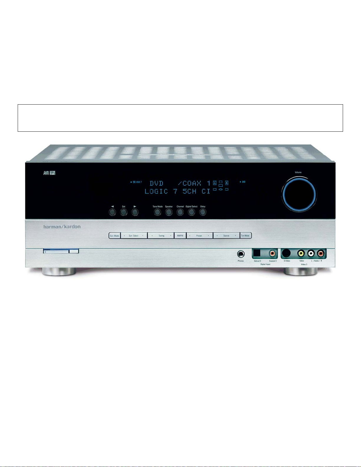
AVR145
5 X 40W 5.1 CHANNEL A/V RECEIVER
SERVICE MANUAL
ESD WAR N ING……………………………….2
LEAKAGE TESTING……………….…..…....3
BASIC SPECIFICATIONS…………………..4
PACKAGING…………………………….……5
FRO NT PANEL CO NTRO L S ………..…..…..6
REAR PANEL CONNECTIONS………….…8
REMOTE CONTROL FUNCTIONS……….10
CONNECTIONS/INSTALLATION………....13
OPERATION………………………...………22
TROUBLESHOOTING GUIDE…...……..…26
REMOTE & PR OCESSOR R ESETS……....26
harman/kardon, Inc.
250 Crossways Park Dr.
Woodbur y, New York 11797 Rev 0 1/ 2007
CONTENTS
DISASSEM BLY ……………………………….27
UNIT EXPLOD ED VIEW…………..…….…..31
EXPLODED VIEW PARTS LIST……………32
AMP BIAS ADJUSTMENT……………….…33
BLOCK DIAGRAM…………………………..34
PCB DRAWINGS……………………………35
ELECTRICAL PARTS LIST………..….……42
SEMICONDUCTOR PINOUTS…….………73
SCHEMATICS………………………………144
WIRING DIAGRAM…………………………151
Page 2

2
AVR145
harman/kardon
Some semiconductor (solid state) devices can be damaged easily by static electricity. Such components commonly are called
Electrostatically Sensitive (ES) Devices. Examples of typical ES devices are integrated circuits and some field effect transistors and
semiconductor "chip" components.
The following techniques should be used to help reduce the incidence of component damage caused by static electricity.
1. Immediately before handling any semiconductor component or semiconductor-equipped assembly, drain off any electrostatic charge on
your body by touching a known earth ground. Alternatively, obtain and wear a commercially available discharging wrist strap device,
which should be removed for potential shock reasons prior to applying power to the unit under test.
2. After removing an electrical assembly equipped with ES devices, place the assembly on a conductive surface such as aluminum foil, to
prevent electrostatic charge build-up or exposure of the assembly.
3. Use only a grounded-tip soldering iron to solder or unsolder ES devices.
4. Use only an anti-static solder removal device. Some solder removal devices not classified as "anti-static" can generate electrical charges
sufficient to damage ES devices.
5. Do not use freon-propelled chemicals. These can generate electrical change sufficient to damage ES devices.
6. Do not remove a replacement ES device from its protective package until immediately before you are ready to install it. (Most replacement
ES devices are packaged with leads electrically shorted together by conductive foam, aluminum foil or comparable conductive material.)
7. Immediately before removing the protective material from the leads of a replacement ES device, touch the protective material to the
chassis or circuit assembly into which the device will be installed.
CAUTION :
8. Minimize bodily motions when handling unpackaged replacement ES devices. (Otherwise harmless motion such as the brushing together
or your clothes fabric or the lifting of your foot from a carpeted floor can generate static electricity sufficient to damage an ES devices.
Be sure no power is applied to the chassis or circuit, and observe all other safety precautions.
Each precaution inthis manualshould be followed during servicing.
Components identified with the IEC symbol in the parts list are special significance to safety. When replacing a component identified with
, use only the replacement parts designated, or parts with the same ratings or resistance, wattage, or voltage that are designated in the
parts list in this manual. Leakage-current or resistance measurements must be made to determine that exposed parts are acceptably
insulated from the supply circuit before retuming the product to the customer.
Page 3
SAFETY PRECAUTIONS
The following check should be performed for the continued
protection of the customer and service technician.
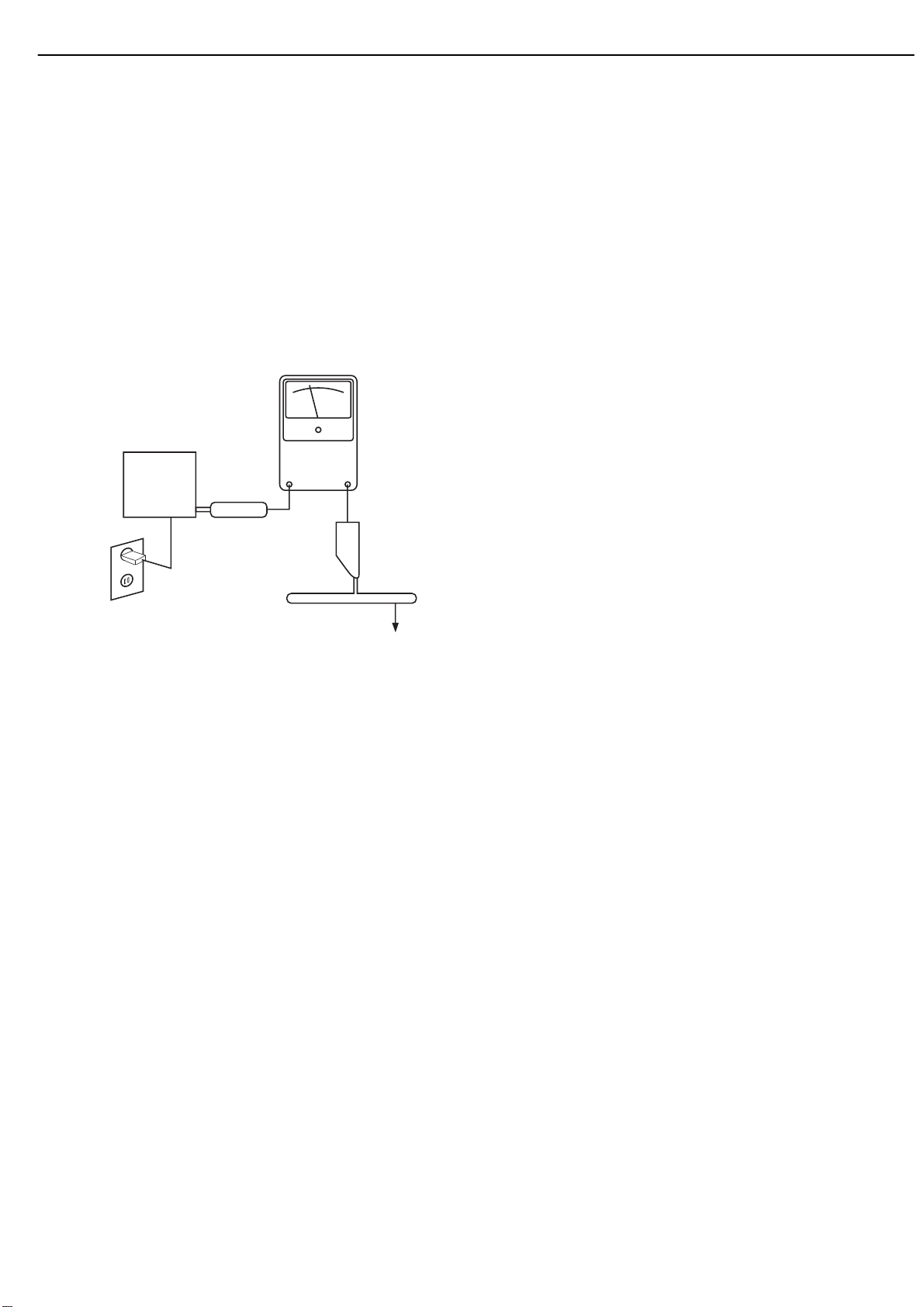
LEAKAGE CURRENT CHECK
Measure leakage current to a known earth ground (water
pipe, conduit, etc.) by connecting a leakage current tester
between the earth ground and all exposed metal parts of the
appliance (input/output terminals, screwheads, metal
overlays, control shaft, etc.). Plug the AC line cord of the
appliance directly into a 120V AC 60Hz outlet and turn the
AC power switch on. Any current measured must not exceed
o.5mA.
ANY MEASUREMENTS NOT WITHIN THE LIMITS
OUTLINED ABOVE ARE INDICATIVE OF A
POTENTIAL SHOCK HAZARD AND MUST BE
CORRECTED BEFORE RETURNING THE APPLIANCE
TO THE CUSTOMER.
3
AVR145
Reading should
not be above
0.5mA
Device
under
test
Leakage
current
tester
harman/kardon
Test all
exposed metal
surfaces
Also test with
plug reversed
(Using AC adapter
plug as required)
Earth
ground
AC Leakage Test
Page 4

46
AVR 145 TECHNICAL SPECIFICATIONS
Audio Section
Stereo Mode
Continuous Average Power (FTC)
50 Watts per channel,20Hz–20kHz,
@ <0.07% THD, both channels driven into 8 ohms
Five-Channel Surround Modes
Power per Individual Channel
Front L&R channels:
40 Watts per channel
@ <0.07% THD, 20Hz–20kHz into 8 ohms
Center channel:
40 Watts @ <0.07% THD,20Hz–20kHz into 8 ohms
Surround (L & R Side) channels:
40 Watts per channel
@ <0.07% THD, 20Hz–20kHz into 8 ohms
Input Sensitivity/Impedance
Linear (High-Level) 200mV/47k ohms
Signal-to-Noise Ratio (IHF-A) 100dB
Surround System Adjacent Channel Separation
Pro Logic I/II 40dB
Dolby Digital (AC-3) 55dB
DTS 55dB
Frequency Response
@ 1W (+0dB,–3dB) 10Hz –130kHz
High Instantaneous
Current Capability (HCC) ±25 Amps
Transient Intermodulation
Distortion (TIM) Unmeasurable
Slew Rate 40V/µsec
FM Tuner Section
Frequency Range 87.5 –108.0MHz
Usable Sensitivity IHF 1.3µV /13.2dBf
Signal-to-Noise Ratio Mono/Stereo 70/68dB
Distortion Mono/Stereo 0.2/0.3%
Stereo Separation 40dB @ 1kHz
Selectivity ±400kHz, 70dB
Image Rejection 80dB
IF Rejection 90dB
AM Tuner Section
Frequency Range 520–1720kHz
Signal-to-Noise Ratio 45dB
Usable Sensitivity Loop 500 µV
Distortion 1kHz, 50% Mod 0.8%
Selectivity ±10kHz, 30dB
Video Section
Television Format NTSC
Input Level/Impedance 1Vp-p /75 ohms
Output Level/Impedance 1Vp-p /75 ohms
Video Frequency Response
(Composite and S-Video) 10Hz–8MHz (–3dB)
Video Frequency Response
(Component Video) 10Hz–100MHz (–3dB)
General
Power Requirement AC 120V/60Hz
Power Consumption 65W idle,540W maximum
(5 channels driven)
Dimensions (Product) (Shipping)
Width 17-5/16 inches (440mm) 22 inches (559mm)
Height 5-7/8 inches (150mm) 10-1/2 inches (267mm)
Depth 13-3/4 inches (350mm) 18-3/4 inches (476mm)
(Product) (Shipping)
Weight 24.4 lb (11.1kg) 29 lb (13.2kg)
Depth measurement includes knobs,buttons and ter minal connections.
Height measurement includes feet and chassis.
All features and specifications are subject to change without notice.
Harman Kardon, Harman International, Designed to Entertain and Logic 7 are trademarks of Harman International
Industries,Incorporated, registered in the United States and/or other countries. and EzSet are trademarks of Harman International Industries,Incorporated.
Dolby,Pro Logic and the double-D symbol are trademarks of Dolby Laboratories.
Manufactured under license from Dolby Laboratories.
DTS,DTS Surround, DTS-ES and DTS Neo:6 are registered trademarks,and DTS 96/24 is a trademark, of DTS,
Inc.
Cirrus Logic is a registered trademark of Cirrus Logic,Inc.
SACD is a trademark of Sony Corporation.
Apple and iPod are registered trademarks,and Shuffle is a trademark, of Apple Computer, Inc.
Blu-ray Disc is a trademark of the Blu-ray Disc Association.
HD-DVD is a trademark of the DVD Format/Logo Licensing Corporation (DVD FLLC).
TiVo is a registered trademark of TiVo Inc.
4
AVR145
harman/kardon
Page 5
5
AVR145
harman/kardon
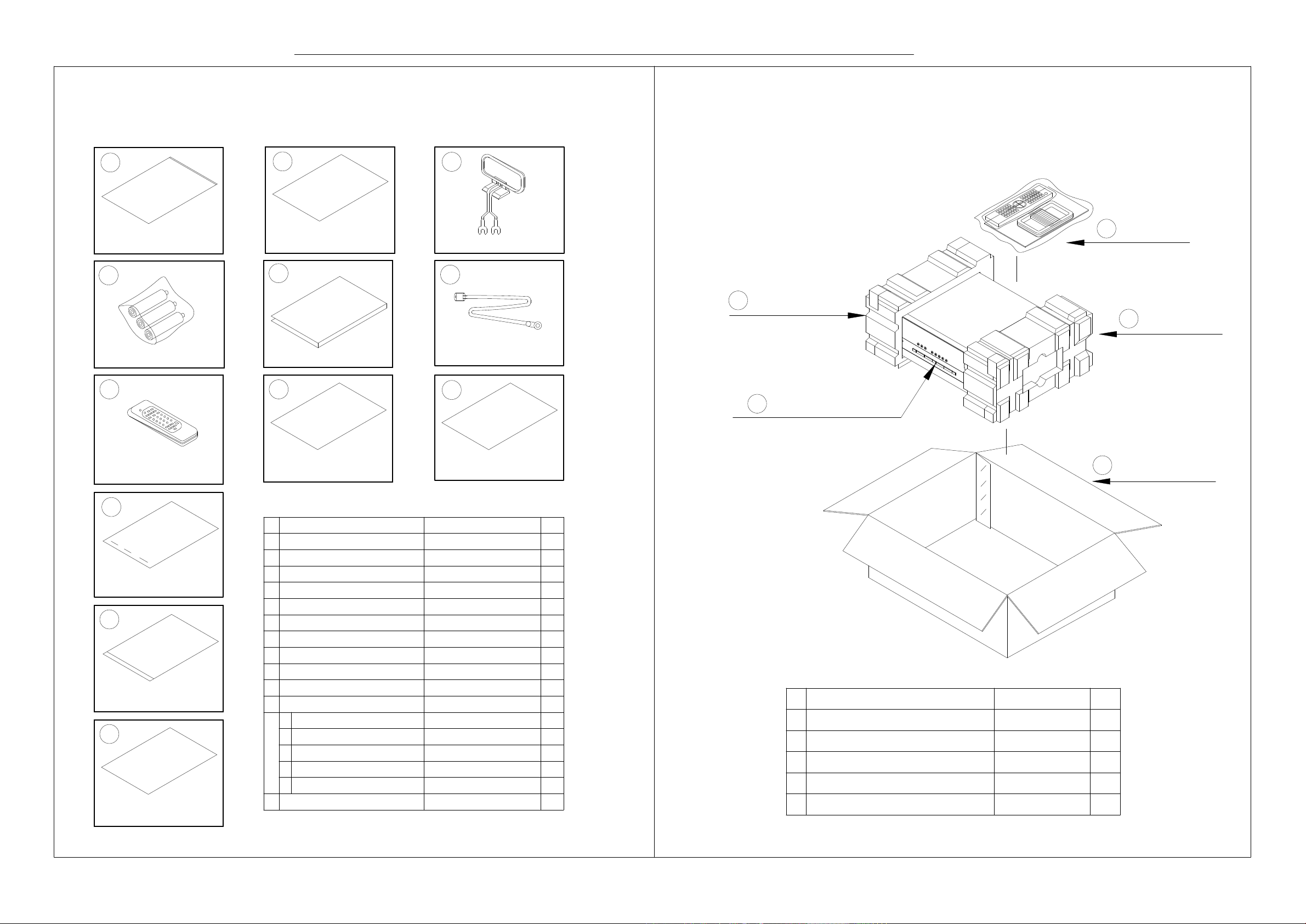
1. Instruction manual ass'y - Accessories 2. Package Drawing
1
2
3
POLY BAG
CARD WARRANTY
AM LOOP ANTENNA ASS'Y
AVR145
MANUAL ASS'Y
1
4
BATTERY ASS'Y
REMOCON
TRANSMITTER ASS'Y
10
STAPLE
11
COVER ASS'Y
12
IMAGE BROCHURES
5
MANUAL INSTRUCTION
87
SHEET GUIDE
NO DESCRIPTION PARTS NO. Q,ty
1
POLY BAG
CARD WARRANTY
2
3
AM LOOP ANTENNA
4
BATTERY
5
INSTRUCTION MANUAL
6
FM 1 POL ANT(UL)
7
REMOCON TRANSMITTER ASS'Y
SHEET GUIDE(QUICK START GUIDE)
8 CQE1A297Z
SHEET INPORTANT9 1
STAPLE10
DOOR KIT
11 CGRAVR130ZA 1
1
FRONT COVER "A", SILVER
2
FRONT COVER "B", SILVER
3
SHEET,FRONT COVER
4
PAD, COVER
5
BAG,POLY
IMAGE BROCHURES12 1
6
FM 1 POLE ANT(UL)
9
SHEET INPORTANT
CQE1A172X 1
CSA1A027Z
CQX1A1132Y
CSA1A019Z 1
CARTAVR145
CGR1A331M7H43
CGR1A332M7H43
CQE1A219Z
CPS1A676
2
SNOW PAD (L)
SNOW PAD (R)
3
AVR 145
4
BOX ,OUT CARTON
5
1
1
3
1
1
1
1
3
DESCRIPTIONNO
1
11
1
1
1
MANUAL ASS'Y
1
2
SNOW,PAD(L)
4
SET AVR145SET 1
BOX,OUT CARTON
5
CPS6A564
CPS6A565SNOW,PAD(R)3 1
CPG1A820Z
Q,tyPARTS NO.
1
1
1
Page 6

7
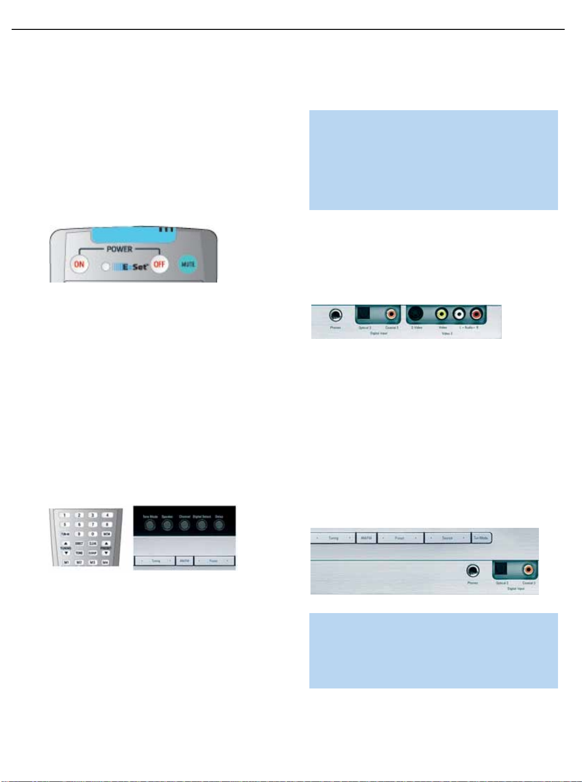
Main Power Switch:This is a mechanical switch that turns the
power supply on or off. It is usually left pressed in (On position) at all
times,and cannot be turned on using the remote control.
Standby/On Switch: This is an electrical switch that turns the
receiver on for playback, or leaves it in standby mode for quick turn-on
using this switch or the remote control.
Power Indicator:This LED has three possible modes.When main
power is turned off, the LED is dark and the receiver won’t respond to
any button presses.When main power is turned on, but before the
Standby/On Switch is used, the LED turns amber and the receiver is
ready to be turned on.When the receiver is turned on, the LED
turns blue.
Source Select: Press this button to select a source device, which is
a component where a playback signal originates,e.g.DVD,CD,cable TV,
satellite or HDTV tuner.
Source Indicators:The name of the current source input lights up.
The indicated input changes each time the Source Select button is
pressed.
Volume Knob:Turn this knob to raise or lower the volume,which will
be shown in decibels (dB) in the Message Display.
Message Display:Various messages appear in this two-line display
in response to commands.When the on-screen display menu system
(OSD) is in use,the message OSD ON will appear to remind you to
check the video display.
Tuner Band: Press this button to select the tuner as the source,or to
switch between the AM and FM bands.
Tuning: Press either side of this button to tune a radio station.
Tuning Mode: This button toggles between manual (one frequency
step at a time) and automatic (seeks frequencies with acceptable signal
strength) tuning mode.It also toggles between stereo and mono modes
when an FM station is tuned.
Preset Stations: Press this button to select a preset radio station.
Headphone Jack: Plug a 1/4" headphone plug into this jack for
private listening.
Surround Mode: Press this button to select a type of surround
sound (e.g. multichannel) mode.Choose from the Dolby modes,DTS
modes,Logic 7 modes,DSP modes or Stereo modes.
Surround Select:After you have selected the desired type of sur-
round mode,press this button to select a specific variant of that type
of mode.
Surround Mode Indicators: One or more of these icons may light
up as you select different surround modes.The Message Display also
indicates the surround mode.
Analog Audio,Video and Digital Audio Inputs: Connect a
source component that will only be used temporarily to these jacks,
such as a camera or game console.Remember to select only one type
of audio and one type of video connection.
Speaker/Channel Input Indicators:The box icons indicate
which speaker positions you have configured, and the size (frequency
range) of each speaker.When a digital audio input is used, letters will
light inside the boxes to indicate which channels are present in the
incoming signal.
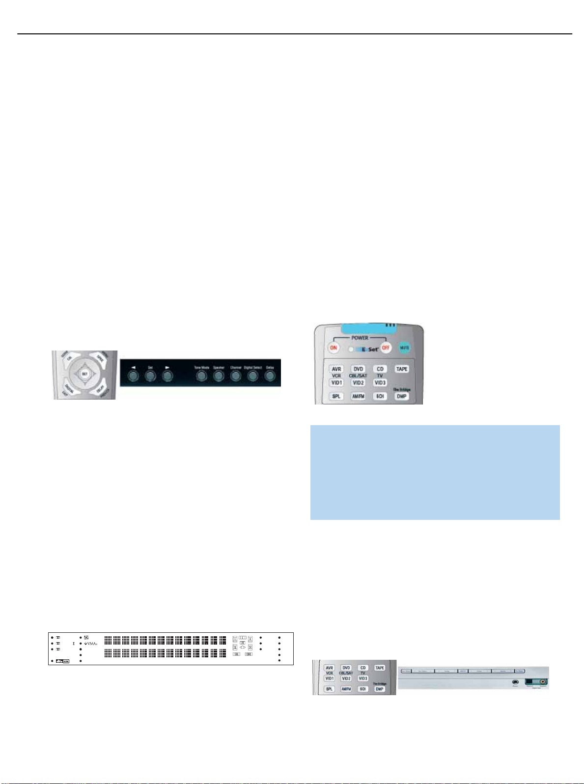
Navigation: These buttons are used together with the following five
buttons to make selections.
Tone Mode: Press this button to access the tone controls (bass and
treble). Use the ‹
/› Navigation buttons to make your selections.
Speaker: Press this button to configure speaker sizes, that is,the fre-
quency-range capability of each speaker.
Channel Level Adjust:Press this button to set the output levels for
each channel so that all speakers sound equally loud at the listening
position.
Digital Input Select: Press this button to select the specific digital
audio input (or analog audio input) you used for the current source.
Delay: Press this button to set delay times that compensate for placing
the speakers at different distances from the listening position.
FRONT-PANEL CONTROLS
6
AVR145
harman/kardon
Page 7
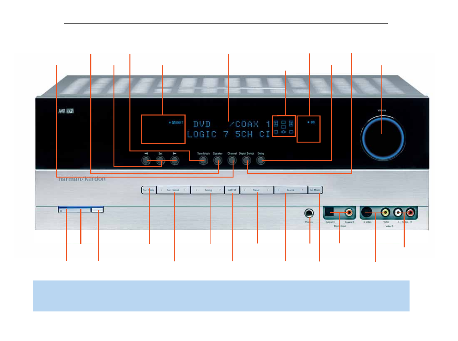
Channel Level
NOTE: To make it easier to follow the instructions throughout the manual that refer to this illustration,a copy of this page may be downloaded from the Product Support section at
www.harmankardon.com
7
Adjust
AVR145
Speaker Size
Setup
Tone Mode
Navigation
Surround Mode Indicators
Message Display
Speaker/Channel
Input Indicators
Source
Indicators
Delay
harman/kardon
Digital Input
Select
Volume
Power
Indicator
Standby/On
Switch
Main Power
Switch
Surround
Mode
Surround
Select
Tuning
Tuner Band
Preset Stations
Source
Select
Headphone
Jack
Tuning
Mode
Digital
Audio Inputs
Analog Audio
Inputs
Video Inputs
Page 8

9
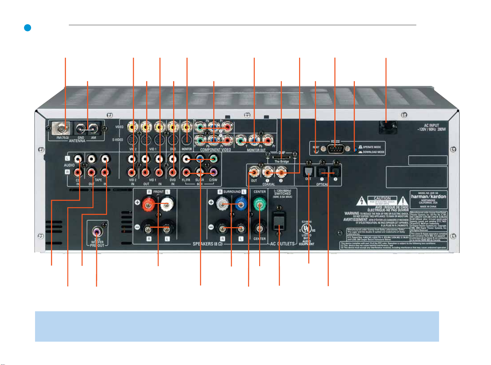
REAR-PANEL CONNECTIONS
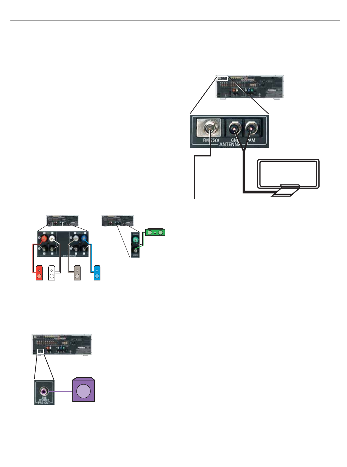
AM and FM Antenna Terminals: Connect the included AM and
FM antennas to their respective terminals for radio reception.
Front,Center and Surround Speaker Outputs: Use two-con-
ductor speaker wire to connect each set of terminals to the correct
speaker. Remember to observe the correct polarity (positive and negative connections).Always connect the positive lead to the colored ter minal on the receiver and the red terminal on the speaker. Connect the
negative lead to the black terminal on both the receiver and the speaker.
See the Connections section for more information on connecting your
speakers.
Subwoofer Output: If you have a powered subwoofer,connect it to
this jack.
Video 1,Video 2 and DVD Audio/Video Inputs:These jacks
may be used to connect your video-capable source components (e.g.,
VCR, DVD player, cable TV box) to the receiver. Remember to use only
one type of video connection for each source.See the Connections
section for more information on audio and video connection options for
each source component.
Video 1 Audio/Video Outputs:These jacks may be used to con-
nect your VCR or another recorder.
Composite and S-Video Monitor Outputs: If some of your
sources use composite or S-video connections,then you will need to
connect one or both of these monitor outputs to the corresponding
inputs on your television or video display in order to view the sources.
CD and Tape Audio Inputs:These jacks may be used to connect
your audio-only source components (e.g., CD player,tape deck). Do not
connect a turntable to these jacks unless you are using the turntable
with a phono preamp.
Tape Outputs: These jacks may be used to connect your CDR or
another audio-only recorder.
Coaxial and Optical Digital Audio Inputs:If your source has
a compatible digital audio output, connect it to one of these jacks for
improved audio performance.Remember to use only one type of digital
audio connection for each source.
Coaxial and Optical Digital Audio Outputs:If your source is
also an audio recorder, you may connect a compatible digital audio output to the recorder’s input for improved recording quality.
The Bridge/DMP Input: Connect the optional Har man Kardon
to this input for use with your iPod (not included).Make
sure the receiver is turned off (in Standby mode) when connecting
The Bridge.
6-Channel Inputs: Connect the analog audio outputs of a DVD-
Audio,SACD
™
, Blu-ray Disc™or HD-DVD™player (or any other external
decoder) to these jacks to enjoy these proprietary formats.
Component Video Inputs: If both your video source (e.g., DVD
player or HDTV tuner) and your television or video display have analog
component video (Y/Pb/Pr) capability, then you may connect the component video outputs of your source to one of the two component video
inputs.Do not make any other video connections to that source.
Component Video Monitor Outputs:If you are using one or
both of the Component Video Inputs and your television or video display
is component-video-capable,you may connect these jacks to the corresponding inputs on your video display. You will also need to connect the
composite and/or S-video monitor outputs to your video display if some
of your sources use those types of video connections.
RS-232 Serial Port:This specialized connector may be used with
your personal computer in case Harman Kardon offers a software
upgrade for the receiver at some time in the future.
RS-232 Mode: Leave this switch popped out in the Operate position
unless the AVR 145 is being upgraded.
RS-232 Reset:This switch is only used during a software upgrade.
A standard processor reset is performed by pressing and holding the
front-panel Tone button.
Switched AC Accessory Outlet: You may plug the AC power
cord of one source device into this outlet, and it will turn on whenever
you turn on the receiver. Do not use a source that consumes more than
50 watts of power.
AC Power Cord:After you have made all other connections,plug the
AC power cord into an unswitched outlet.
8
AVR145
The
Bridge
TM
harman/kardon
Page 9
10
NOTE: To make it easier to follow the instructions throughout the manual that refer to this illustration,a copy of this page may be downloaded from the Product Support section at
www.harmankardon.com
9
FM Antenna
AVR145
AM Antenna
Video 2
A/V
Inputs
Video 1
A/V
Outputs
Video 1
A/V
Inputs
Video
Monitor
Outputs
DVD A/V
Inputs
Component Video
Inputs (1 & 2)
Component Video
Monitor Outputs
The Bridge/
DMP Input
Coaxial Digital
Audio Inputs
(1 & 2)
RS-232
Reset
RS-232
Serial Port
RS-232
Mode
harman/kardon
AC Power
Cord
CD
Inputs
Tape
Outputs
Tape
Inputs
Subwoofer
Output
Front
Speaker
Outputs
6-Channel
Inputs
Surround
Speaker
Outputs
Coaxial Digital
Audio Output
Center
Speaker
Outputs
Switched AC
Accessory
Outlet
Optical Digital
Audio Output
Optical Digital
Audio Inputs (1 & 2)
Page 10

11
The AVR 145 remote is capable of controlling nine devices,including
the AVR itself and an iPod docked in the optional The Bridge accessory.
During the installation process,you may program the codes for each of
your source components into the remote.Each time you wish to use the
codes for any component, you will need to first press the Selector button for that component.This changes the button functions to the appropriate codes for that product.
Each Input Selector has been preprogrammed to control certain types
of components,with only the codes specific to each brand and model
changing,depending on which product code is programmed. The
device types programmed into each selector may not be changed.
DVD: Controls DVD players and recorders.
CD: Controls CD players and recorders.
Tape: Controls cassette decks.
Video 1: Controls VCRs,TiVo and DVRs.
Video 2: Controls cable and satellite television set-top boxes.
Video 3: Controls televisions and other video displays.
The Bridge/DMP: Controls an iPod docked in The Bridge.
For example, if you have inserted a disc in your CD player and Iyou
would like to skip ahead three tracks,but you then find that the volume
is too loud, you would follow this procedure:
1. Press the CD Input Selector to switch to the codes that control your
CD player.
2. Press the Play Button (in the Transport Controls section) if the disc is
not already playing.
3. Press the Skip Up Button three times to advance three tracks.
4. Press the AVR Button so that you can access the Volume Controls.
5. Press the Volume Down Button until the volume level is satisfactory.
Any given button may have different functions,depending on which
component is being controlled. Some buttons are labeled with these
functions.For example,the Sleep and DSP Surround Buttons are
labeled for use as Channel Up/Down Buttons when controlling a television or cable box. See Table A8 in the appendix for listings of the
different functions for each type of component.
IR Transmitter Lens: As buttons are pressed on the remote,
infrared codes are emitted through this lens.Make sure it is pointing
toward the component being operated.
EzSet™Microphone:This microphone “hears” the test tone used
during the EzSet level-setting procedure.Make sure it is pointing toward
the receiver when running EzSet.
Power On Button: Press this button to turn on the AVR or another
device.The Master Power Switch on the AVR 145’s front panel must
first have been switched on.
Mute Button: Press this button to mute the AVR 145’s speaker and
headphones outputs temporarily. To end the muting, press this button
or adjust the volume.Muting is also canceled when the receiver is
turned off.
Program/EzSet Indicator:This LED lights up or flashes in one of
three colors as the remote is programmed with codes,and during the EzSet
procedure.
Power Off Button: Press this button to turn off the AVR 145 or
another device.
AVR Selector:Press this button to switch the remote to the codes
that operate the receiver.
Input Selectors: Press one of these buttons to select a source
device,which is a component where a playback signal originates,e.g.,
DVD, CD,cable TV, satellite or HDTV tuner.This will also turn on the
receiver and switch the remote to the codes that operate the source
device.
AM/FM Button: Press this button to select the tuner as the source,
or to switch between the AM and FM bands.
6-Channel Input Selector: Press this button to select the 6-
Channel Inputs as the audio source.The receiver will use the video input
and remote control codes for the last-selected video source.
EzSet (SPL) Button:Press this button to run the EzSet output-level
calibration procedure.Make sure to point the remote toward the receiver
during EzSet.
The Bridge/DMP Selector: Press this button to select an iPod
docked in the optional The Bridge as the audio source.The remote will
switch to the codes that operate the iPod.
Test T one:Press this button to activate the test tone for manual out-
put-level calibration.
TV/Video: This button has no effect on the receiver,but is used to
switch video inputs on some video source components.
Sleep Button: Press this button to activate the sleep timer,which
shuts off the receiver after a programmed period of time of up to
90 minutes.
Volume Controls: Press these buttons to raise or lower the volume,
which will be shown in decibels (dB) in the Message Display.
DSP Surround: Press this button to select a DSP surround mode
(Hall 1, Hall 2, Theater).
On-Screen Display (OSD): Press this button to activate the on-
screen menu system.
Channel Level: Press this button to set the output levels for each
channel so that all speakers sound equally loud at the listening position.
Usually this is done while playing an audio selection,such as a favorite CD,
after you have calibrated the levels using EzSet,as described in the Getting
Started section.
REMOTE CONTROL FUNCTIONS
10
AVR145
harman/kardon
Page 11

13
REMOTE CONTROL FUNCTIONS
Speaker Setup: Press this button to configure speaker sizes, that is,
the frequency-range capability of each speaker. Usually this is done
using the on-screen menu system, as described in the Getting Started
section.
Navigation and Set Buttons:These buttons are used together to
make selections within the on-screen menu system, or when accessing
the functions of the four buttons surrounding this area of the remote –
Channel Level, Speaker Setup,Digital Input or Delay.
Digital Input Select: Press this button to select the specific digital
audio input (or analog audio input) you used for the current source.
Delay: Press this button to set delay times that compensate for placing
the speakers at different distances from the listening position, or to
resolve a “lip sync”issue that may be caused by digital video processing.This is done using the on-screen menu system, as described in the
Initial Setup section.
Numeric Keys: Use these buttons to enter radio station frequencies
when using the tuner (after pressing the Direct Button), or to select station
presets.
Tuning Mode: This button toggles between manual (one frequency
step at a time) and automatic (seeks frequencies with acceptable signal
strength) tuning mode.It also toggles between stereo and mono modes
when an FM station is tuned.
Memory: After you have tuned a particular radio station, press this
button, then the numeric keys,to save that station as a radio preset.
Tuning: Press these buttons to tune a radio station. Depending on
whether the tuning mode has been set to manual or automatic,each
press will either change one frequency step at a time,or seek the next
frequency with acceptable signal strength.
Direct: Press this button before using the Numeric Keys to directly
enter a radio station frequency.
Clear: Press this button to clear a radio station frequency you have
started to enter.
Preset Stations Selector: Press these buttons to select a preset
radio station.
Tone Mode: Press this button to access the tone controls (bass and
treble). Use the Navigation buttons to make your selections.
Disc Skip:This button has no effect on the receiver, but is used with
some optical disc changers to skip to the next disc.
Macros: These buttons may be programmed to execute long com-
mand sequences with a single button press.They are useful for programming the command to turn on or off all of your components,or for
accessing specialized functions for a different component than you are
currently operating.
Surround Mode Selectors: Press any of these buttons to select
a type of surround sound (e.g., multichannel) mode.Choose from the
Dolby modes,DTS modes,Logic 7 modes or Stereo modes.Each
press of a button will cycle to the next available variant of that mode.
Not all modes or mode groups are available with all sources.
Night Mode: Press this button to activate Night mode with specially
encoded Dolby Digital discs or broadcasts.Night mode compresses the
audio so that louder passages are reduced in volume to avoid disturbing
others,while dialogue remains intelligible.
Track Skip: These buttons have no effect on the receiver,but are
used with many source components to change tracks or chapters.
Dim: Press this button to partially or fully dim the front-panel display.
Transport Controls: These buttons have no effect on the receiver,
but are used to control many source components.By default, when the
remote is operating the receiver, these buttons will control a DVD player.
11
AVR145
harman/kardon
Page 12
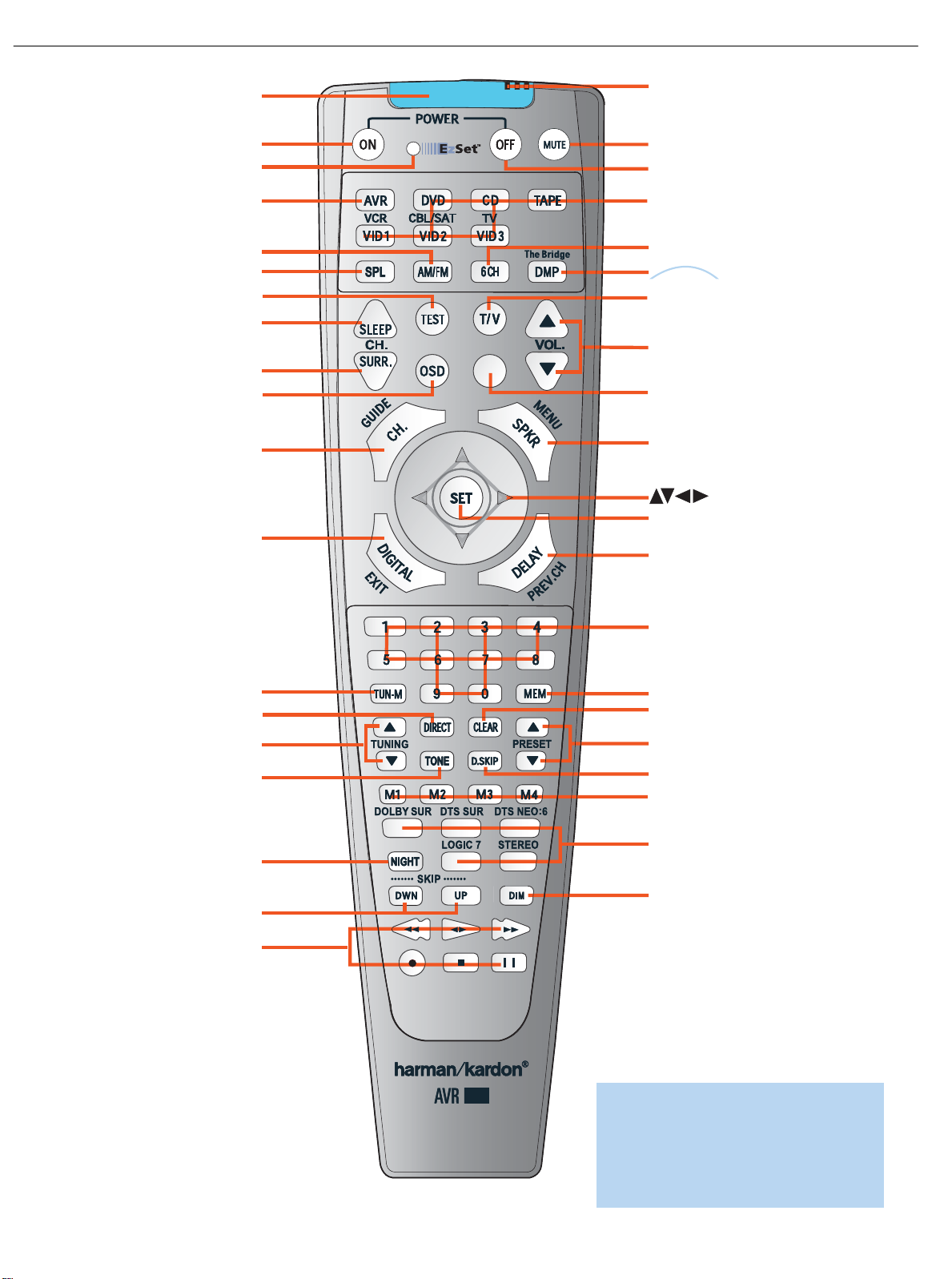
IR T ransmitter Lens
Program/EzSet Indicator
Power On
AVR Selector
AM/FM
EzSet (SPL)
Test T one
Sleep
DSP Surround
On-Screen Display
Channel Level
Digital Input
Tuning Mode
Direct Station Entry
Tuning
Tone Mode
Night Mode
Track Skip
Transport Controls
EzSet Microphone
Power Off
Mute
Input Selectors
6-Channel Input Selector
/DMP Selector
TV/Video
Volume Control
Not Used
Speaker Setup
Set
Numeric Keys
Delay
Memory
Clear
Preset Stations Selectors
Disc Skip
Macros
Surround Mode Selectors
Dim
The
Bridge
TM
145
NOTE: To make it easier to follow the instructions throughout the manual that refer to this
illustration, a copy of this page may be downloaded from the Product Support section at
www.harmankardon.com
12
AVR145
harman/kardon
Page 13
15
CONNECTIONS
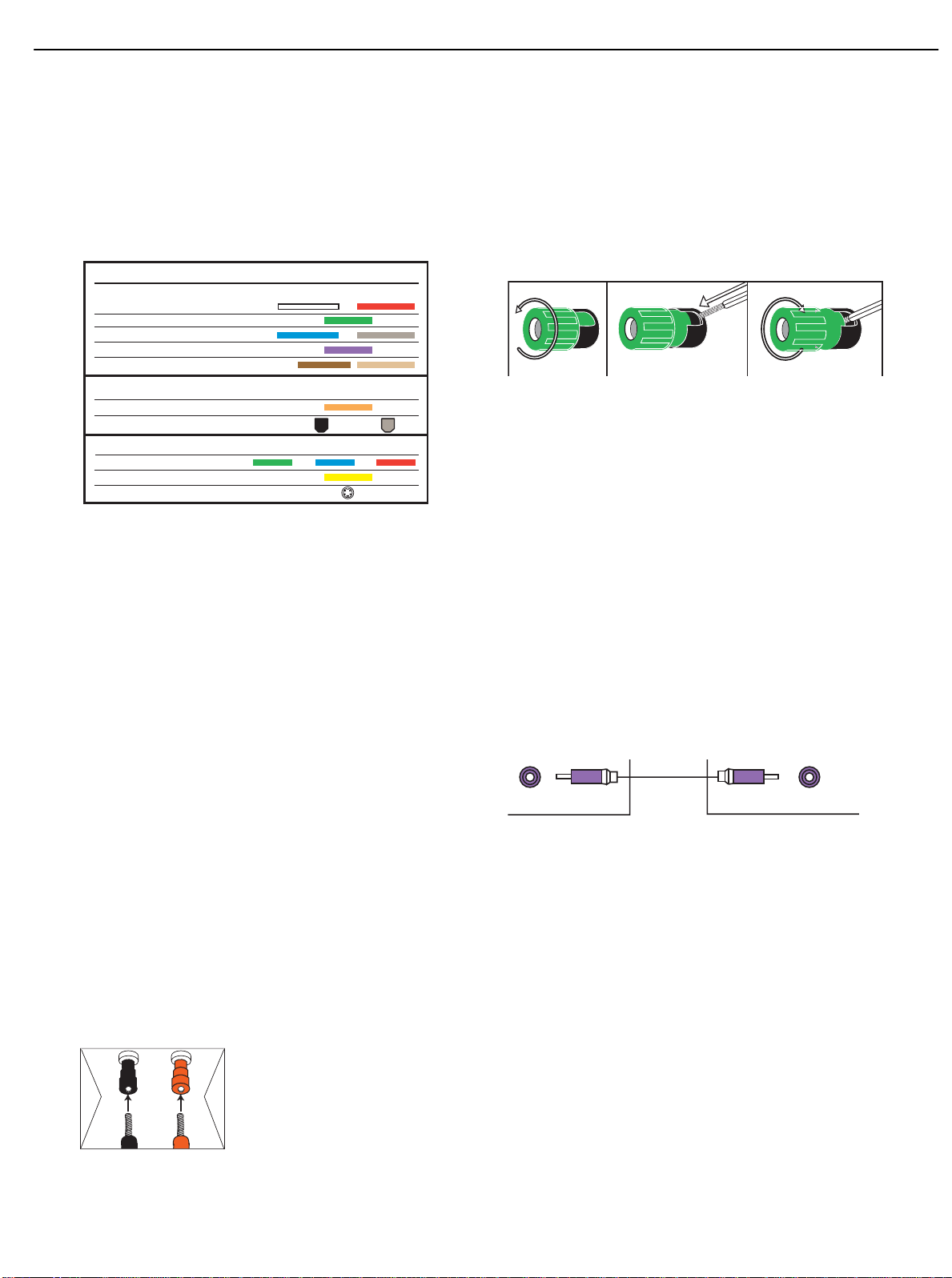
There are different types of audio and video connections used to connect the receiver to the speakers and video display, and to connect
the source devices to the receiver.To make it easier to keep them all
straight, the Consumer Electronics Association (CEA) has established a
color-coding standard.Table 1 may be helpful to you as a reference
while you set up your system.
Table 1– Connection Color Guide
Types of Cables
This section will briefly review different types of cables and connections
that you may use to set up your system.
Speaker Cables
Speaker cables carry an amplified signal from the receiver’s speaker terminals to each loudspeaker. Speaker cables generally contain two wire
conductors,or leads,inside plastic insulation.The two conductors are
usually differentiated in some way, by using different colors, or stripes,or
even by adding a ridge to the insulation. Sometimes the actual wires are
different, one being copper red and the other silver.
The differentiation is important because each speaker must be connected to the receiver’s speaker-output terminals using two wires,one positive (+) and one negative (–).This is called speaker polarity.It’s important to maintain the proper polarity for all speakers in the system. If
some speakers have their negative terminals connected to the receiver’s
positive terminals,performance can suffer,especially for the low frequencies.
Always connect the positive terminal on the loudspeaker, which is usually
colored red, to the positive terminal on the receiver,which is colored as
shown in the Connection Color Guide (Table 1). Similarly,always connect the black negative terminal on the speaker to the black negative
terminal on the receiver.
The AVR 145 uses binding-post speaker
terminals that can accept banana plugs
or bare-wire cables.
Banana plugs are simply plugged into the
hole in the middle of the terminal cap.
Figure 1 – Binding-Post Speaker
Terminals With Banana Plugs
Bare wire cables are installed as follows:
1. Unscrew the terminal cap until the pass-through hole in the collar is
revealed.
2. Insert the bare end of the wire into the hole.
3. Screw the cap back into place until the wire is held snugly.
Figure 2 – Binding-Post Speaker Terminals With Bare Wires
Subwoofer
The subwoofer is a specialized type of loudspeaker that is usually connected in a different way. The subwoofer is used to play only the low
frequencies (bass), which require much more power than the other
speaker channels.In order to obtain the best results,most speaker
manufacturers offer powered subwoofers,in which the speaker contains
its own amplifier on board. Sometimes the subwoofer is connected to
the receiver using the front left and right speaker outputs,and then the
front left and right speakers are connected to terminals on the subwoofer. More often, a line-level (nonamplified) connection is made
from the receiver’s Subwoofer Output to a corresponding jack on the
subwoofer.
Although the subwoofer output looks similar to the analog audio jacks
used for the various components,it is filtered and only allows the low
frequencies to pass.Don’t connect this output to your other devices.
Although doing so won’t cause any harm, performance will suffer.
Figure 3 – Subwoofer
Connecting Source Devices to the AVR
The AVR 145 is designed to process audio and video input signals,
playing back the audio and displaying the video on a television or monitor connected to the AVR. These signals originate in what are known as
“source devices,” including your DVD player,CD player,DVR (digital
video recorder) or other recorder, tape deck, game console, cable or
satellite television box or MP3 player.Although the tuner is built into the
AVR,it also counts as a source, even though no external connections
are needed, other than the FM and AM antennas.
In general, separate connections are required for the audio and video
portions of the signal.The types of connections used depend upon
what’s available on the source device, and for video signals, the capabilities of your video display.
13
AVR145
Audio Connections
Left Right
Front (FL/FR)
Center (C)
Surround (SL/SR)
Subwoofer (SUB)
Surround Back (SBL/SBR)
Digital Audio Connections
Coaxial
Optical Input Output
Video Connections
Component Y Pb Pr
Composite
S-Video
12 3
+
Pre-out
harman/kardon
Subwoofer
Page 14
16
CONNECTIONS
Audio Connections
There are two formats for audio connections: digital and analog. Digital
audio signals are of higher quality, and are required for listening to
sources encoded with digital surround modes,such as Dolby Digital and
DTS. There are two types of digital audio connections commonly used:
coaxial and optical. Either type of digital audio connection may be used
for each source device,but never both simultaneously for the same
source.However,it’s okay to make both analog and digital audio connections at the same time to the same source.
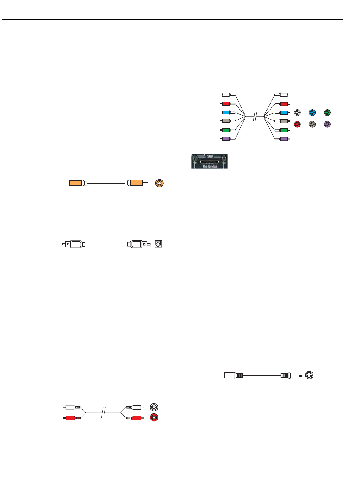
Digital Audio
Coaxial digital audio jacks are usually color-coded in orange.Although
they look similar to analog jacks,they should not be confused, and you
should not connect coaxial digital audio outputs to analog inputs or
vice versa.
Figure 4 – Coaxial Digital Audio
Optical digital audio connectors are normally covered by a shutter to
protect them from dust.The shutter opens as the cable is inserted.Input
connectors are color-coded using a black shutter, while outputs use a
gray shutter.
Figure 5 – Optical Digital Audio
Due to the nature of digital signals as binary bits,they aren’t subject
to signal degradation the way analog signals are.Therefore,the quality
of coaxial and optical digital audio connections should be the same,
although it is important to limit the length of the cable.Whichever type of
connection you choose,Harman Kardon recommends that you always
select the highest quality cables available within your budget.
Analog Audio
Analog connections require two cables,one for the left channel (white)
and one for the right channel (red).These two cables are often attached
to each other for most of their length. Most sources that have digital
audio jacks also have analog audio jacks,although some older types of
sources,such as tape decks,have only analog jacks.For sources that
are capable of both digital and analog audio,you may wish to make
both connections.If you wish to record materials from DVDs or other
copy-protected sources,you may only be able to do so using analog
connections.Remember to comply with all laws regarding copyright if
you choose to make a copy for your own personal use.
Figure 6 – Analog Audio
Multichannel analog connections are used with advanced sources where
the digital content is copy-protected and all surround processing is performed inside the source.These types of connections are usually used
with DVD-Audio,SACD,Blu-ray Disc, HD-DVD and other advanced
players.
Figure 7 – Multichannel Analog Audio
Figure 8 – The Bridge
Harman Kardon receivers also include a proprietary,dedicated audio
connection called “The Bridge/DMP”.If you own an iPod with a dock
connector, you may separately purchase The Bridge and connect it to
The Bridge/DMP port on the receiver. Dock your iPod (not included) in
The Bridge,and you may listen to your materials through your high-performance audio system.You may even use the AVR 145 remote to
control the iPod,with navigation messages displayed on the front panel
and on the screen of a video display connected to the AVR.
Video Connections
Although some sources produce an audio signal only (e.g., CD player,
tape deck), many sources output both audio and video signals (e.g.,
DVD player, cable television box, HDTV tuner,satellite box, VCR, DVR).
In addition to the audio connection, you will need to connect one type of
video connection for each source (never more than one at the same
time for any source).
There are three types of analog video connections: composite video,
S-video and component video.
Composite video is the basic connection most commonly available.The
jack is usually color-coded yellow,and looks like an analog audio jack,
although it is important never to confuse the two.Do not connect a
composite video jack to an analog or coaxial digital audio jack, and vice
versa. Both the chrominance (color) and luminance (intensity) components of the video signal are transmitted using a single cable.
Figure 9 – Composite Video
A
Optical
14
AVR145
Multichannel
analog audio
cable (RCA)
harman/kardon
Front Surround Center
Subwoofer
Coaxial digital
audio cable
Coaxial
Optical digital
audio cable
Composite
video cable
nalog audio
cable (RCA)
L
R
Page 15
17
CONNECTIONS
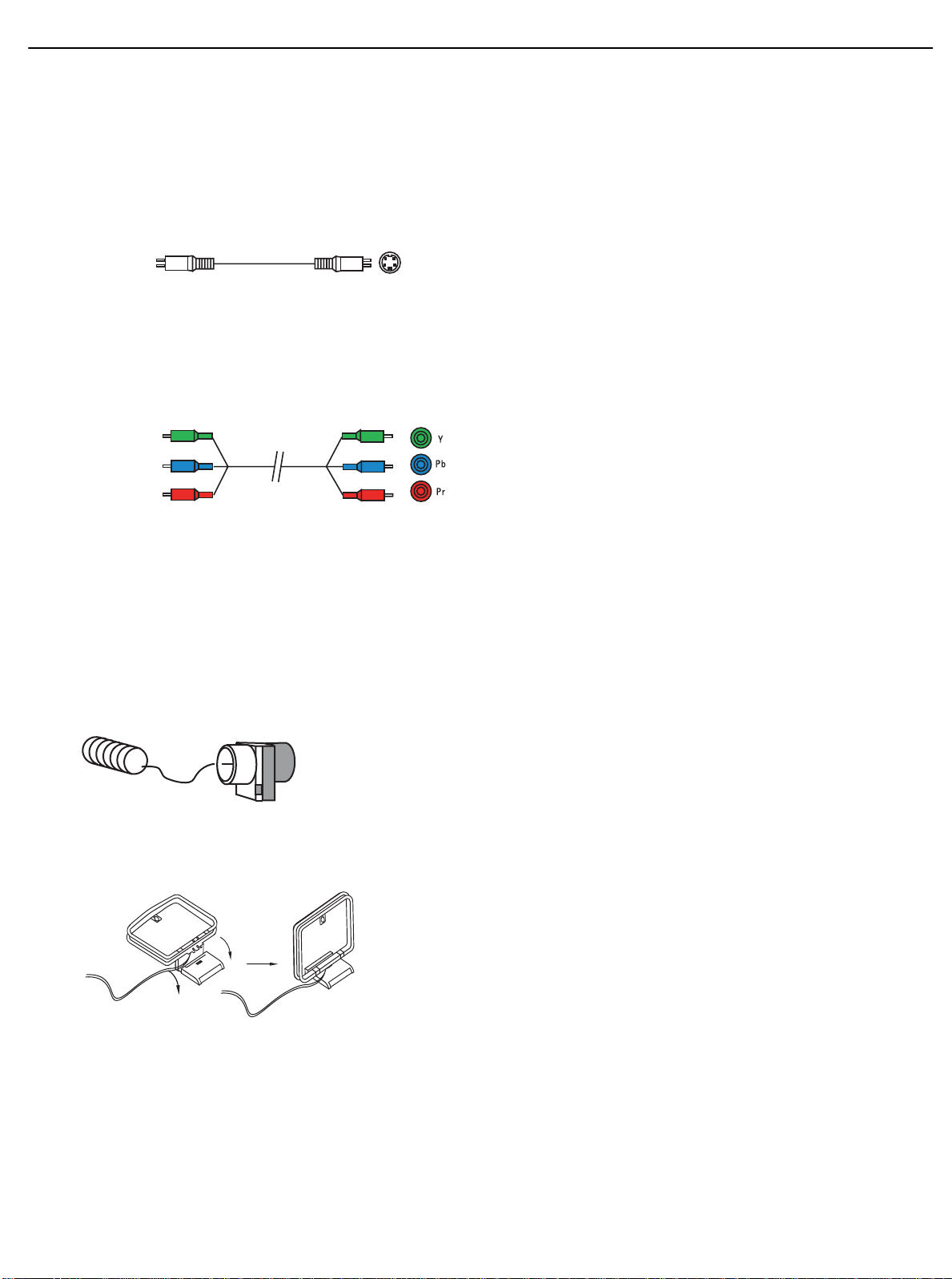
S-video,or “separate” video,transmits the chrominance and luminance
components using separate wires contained within a single cable.The
plug on an S-video cable contains four metal pins,plus a plastic guide
pin. Be careful to line up the plug correctly when you insert it into the
jack on the receiver, source or video display.
Figure 10 – S-Video
Component video separates the video signal into three components –
one luminance (“Y”) and two subsampled color signals (“Pb” and “Pr”) –
that are transmitted using three separate cables.The “Y”cable is colorcoded green, the “Pb” cable is colored blue and the “Pr”cable is colored red.
Figure 11 – Component Video
If it’s available on your video display, component video is recommended as the best quality connection, followed by S-video and then
composite video.
Antennas
The AVR 145 uses separate terminals for the included FM and AM
antennas that provide proper reception for the tuner.
The FM antenna uses a 75-ohm F-connector.
Figure 12 – FM Antenna
The AM loop antenna needs to be assembled.Then connect the two
leads to the screw terminals on the receiver.
Figure 13 – AMAntenna
RS-232 Serial Port
The RS-232 serial port on the AVR 145 is used only for data. If
Harman Kardon releases a software upgrade for the receiver’s operating
system at some time in the future,the upgrade may be downloaded
to the AVR using this port. Complete instructions will be provided at
that time.
C
15
AVR145
omposite
video cable
Component
video cable
harman/kardon
Page 16
19
INSTALLATION
You are now ready to connect your various components to your receiver.
Before beginning,make sure that all components, including the AVR 145,
are turned completely off and their power cords are unplugged. Don’t
plug any of the power cords back in until you have finished
making all of your connections.
Remember that your receiver generates heat while it is playing.Select a
location that leaves several inches of space on all sides of the receiver. It
is preferable to avoid completely enclosing the receiver inside a cabinet.
It is also preferable to stack components on separate shelves rather
than directly on top of the receiver. Some surface finishes are delicate.
Try to select a location with a sturdy surface finish.
Step One – Connect the Speakers
If you have not yet done so,place your speakers in the listening room
as described in the Speaker Placement section above.
Connect the center, front left, front right, surround left and surround right
loudspeakers to the corresponding speaker terminals on the AVR 145.
Remember to maintain the proper polarity by always connecting the
positive and negative terminals on each speaker to the positive and
negative terminals on the receiver. Use the Connection Color Guide
on page 15 as a reference.
Figure 15 – Speaker Connections
Step Two – Connect the Subwoofer
Connect the Subwoofer Output on the AVR 145 to the line-level input on
your subwoofer. Consult the manufacturer’s guide for the subwoofer for
additional information.
Figure 16 – Subwoofer Connection
Step Three – Connect the Antennas
Connect the FM and AM antennas to their terminals.
Figure 17 – Antenna Connections
Step Four – Connect the Source Components
Use the worksheets in the Appendix to note which connections you will
use for each of your source devices.
For each source, select a source input (Video 1, Video 2, Video 3, etc.).
In Table 2 we recommend connecting certain types of sources to certain
source inputs to make it easier to program and use the remote control.
Decide which audio connections you will use.If your source device has
them, use
either
the coaxial digital or the optical digital audio connection. Referring to Table 2, we recommend you connect the DVD source
to the Coaxial 1 input jack, and the source designated Video 2 to the
Optical 2 input jack. However, you may make whatever connections are
best for your system.
In addition to the digital audio connections,we recommend that you
connect the analog audio connections for each source,as a backup to
the digital connections.For sources that don’t have digital audio outputs,
you must use the analog audio connections.
For each video source, select one type of video connection. Component
video is preferred, but both your source device and your video display
must have this type of video capability. If either device does not, then
use S-video.Again, if either your source device or your video display
doesn’t have S-video connections,then use composite video.
Referring to Table 2, we recommend that you connect the DVD source
to the Component Video 1 inputs, and any one source designated as
Video 1,Video 2 or Video 3 to the Component Video 2 inputs. However,
you may make whatever video connections are best for your system.
16
AVR145
AVR 145
harman/kardon
AVR 145
FR FL SR SL
AVR 145
C
AM
FM
AVR 145
SUB
Page 17
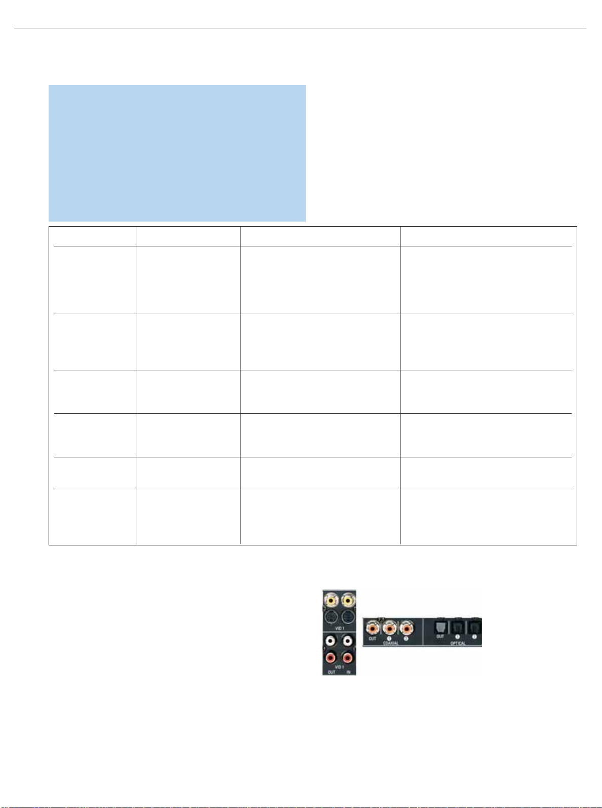
Video 1 Source
Since this source includes audio and video recording output jacks,it is
best suited to a video recorder, such as your VCR or DVR.
Referring to Table 2, connect your recorder to the Video 1 Analog Audio
inputs and outputs and to either the Coax 2 or Optical 2 digital audio
input (and corresponding digital audio output). Use either the Video 1
S-video or composite video input and output if you wish to make
recordings.If you don’t plan on recording, you may use the Component
Video 2 inputs.
Figure 18 – Video 1 A/V Inputs and Outputs, and Digital Audio Inputs
Remember to connect the audio and video
output
jacks on your
recorder to the Video 1 or digital audio
input
jacks on the AVR, and the
audio and video
input
jacks on your recorder to the Video 1 or digital
audio
output
jacks on the AVR.
Device Type AVR 145 Source Input Audio Connections Video Connections
VCR, DVR, PVR, Video 1 • Video 1 Analog (inputs and outputs) •
One
of component Video 2,Video 1 S-video
TiVo or other and or Video 1 composite video
audio/video recorder • Either Coax 2 or Optical 2, with • For recording,use Video 1 S-video or
corresponding coax or optical digital composite video output, and do not use
output component video connections at all
Cable TV, Satellite, Video 2 • Video 2 Analog and •
One
of component Video 2,Video 2
HDTV or other • Optical 1 S-video,Video 2 composite video
device that delivers
television programs
TV, game console, Video 3 (front-panel jacks) • Video 3 Analog and •
One
of component Video 2,Video 3 S-video
camera or other •
Either
Coax 3 or Optical 3
or
Video 3 composite video
audio/video device
DVD Audio/Video, DVD • DVD Analog • Component Video 1
SACD HD-DVD, • 6-Channel inputs (optional) and
Blu-ray Disc • Coax 1
CD player CD • CD Analog and • Not required
•
Either
Coax 2 or Optical 2
CDR, MiniDisc, Tape • Tape Analog (inputs and outputs) and • Not required
cassette •
Either
Coax 2 or Optical 2
• Use corresponding coax or
optical digital output
20
INSTALLATION
NOTE: It’s possible for a source to use none of the connections
named for that source.For example,you might connect your
DVD player to the Component Video 1 inputs and the Coax 1
digital audio input. However, we will refer to this source as
“DVD”,and in Step Five of the Initial Setup section you will program the receiver so that these connections are assigned to the
DVD source.When you select “DVD”as your source using the
front panel or the remote,the correct connections for your DVD
player will be used.
We recommend connecting your various sources using the connections
shown in Table 2 below in order to simplify programming your receiver
and remote control. However, you may connect any device to any
source input.
Table 2 – Recommended Source Component Connections
17
AVR145
harman/kardon
Page 18
21
INSTALLATION STEPS
NOTE: It isn’t possible to make recordings using component
video connections.Keep this in mind as you connect other
source devices that you may wish to make recordings from.
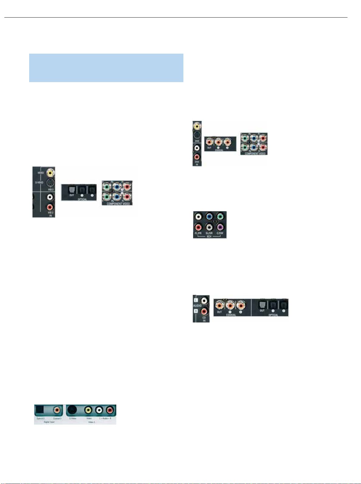
Video 2 Source
The Video 2 source is used only for playback,never recording.The
AVR145 remote control is programmed to operate many brands and
models of cable and satellite television devices,and we recommend
connecting your cable or satellite set-top box to this source.
Referring to Table 2, connect your set-top box to the Video 2 Analog
Audio inputs and to the Optical 1 Digital Audio input. If possible,use
the Component Video 2 inputs. Otherwise,connect the set-top box’s
S-video or composite video output to the matching Video 2 video input.
Figure 19 – Video 2 A/V, DIgital Audio and Component Video Inputs
NOTE: If you receive your television programming using your TV
with an antenna or direct cable connection, then you will need
to connect the analog and optical digital audio (if available on
your TV) outputs to the Video 2 Analog Audio inputs and to the
Optical 1 Digital Audio input.Do not connect any video output
on the television set to any video input on the receiver. See
Step Five for information on connecting the receiver’s video
monitor outputs to the television.
Video 3 Source
The Video 3 source is used only for playback,never recording. It is also
generally reserved for components that are only temporarily connected
to the receiver, such as cameras and game consoles.When not in use,
you may place the supplied covers over the front-panel Video 3 jacks
for a cleaner appearance.Simply snap the covers in place.When you
wish to use the jacks,gently press on the left side of each cover to pivot
it out for removal.
Referring to Table 2, connect your camera or game console to the
Video 3 Analog Audio inputs and to either the Coaxial 3 or Optical 3
digital audio input. If possible,use the Component Video 2 inputs.
Otherwise,connect the component’s S-video or composite video
output to the matching Video 3 video input.
Figure 20 – Video 3 A/V and Digital Audio Inputs
DVD
The DVD source is used for a DVD player. If you have a more advanced
multichannel device,such as a Blu-ray Disc or HD-DVD player,connect
it to the DVD source.
Referring to Table 2, connect your DVD player to the DVD Analog Audio
inputs and to the Coaxial 1 Digital Audio input.If possible,use the
Component Video 1 inputs. Otherwise,connect the DVD player’s S-video
or composite video output to the matching DVD video input.
Figure 21 – DVD A/V,DIgital Audio and Component Video Inputs
If your DVD player plays multichannel lossless discs,such as SACD or
DVD-Audio,you will also need to connect the 6-channel analog audio
outputs on the DVD player to the 6-channel analog audio inputs on the
receiver in order to enjoy these discs to their fullest.
Figure 22 – 6-Channel Analog Audio Inputs
CD
The CD source is used for a strictly audio device,such as a CD player.
Referring to Table 2, connect your CD player to the CD Analog Audio
inputs and to the Coaxial 2 or Optical 2 Digital Audio input.
Figure 23 – CD Audio Inputs and Digital Audio Inputs
No video connections are made,although if your system has unusual
requirements,you may connect a video device using component video
outputs to the Component Video 2 inputs on the receiver, if those jacks
are not in use by another device.
Tape
The Tape source is used for audio-only recorders, such as a CDR,
MiniDisc or cassette deck.
Referring to Table 2, connect your recorder to the Tape Analog Audio
inputs and outputs,and to either the Coax 2 or Optical 2 Digital Audio
input (and corresponding digital audio output).
18
AVR145
harman/kardon
Page 19
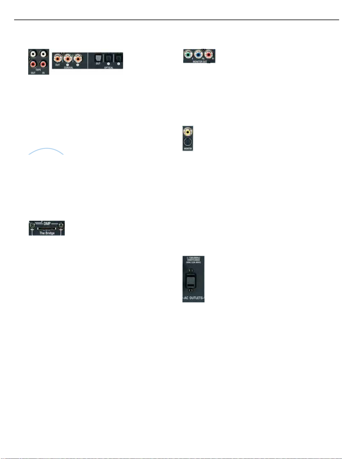
Figure 24 – Tape Audio Inputs and Outputs,and Digital Audio Inputs and Outputs
Remember to connect the
output
jacks on your recorder to the Tape
or digital audio
input
jacks on the AVR, and the
input
jacks on your
recorder to the Tape or digital audio
output
jacks on the AVR.
No video connections are made,although if your system has unusual
requirements,you may connect a video device using component video
outputs to the component Video 2 inputs on the receiver, if those jacks
are not in use by another device.
With Harman Kardon’s optional The Bridge, you can listen to audio
stored on your iPod (not included),use your AVR 145 remote
control to operate the iPod,and even charge the iPod while it’s
docked in The Bridge.
Simply plug the proprietary cable from The Bridge into the special
The Bridge/DMP connector on the rear of the AVR 145’s.Refer to the
owner’s manual for The Bridge to select the appropriate insert to
match your iPod.
Figure 25 – The Bridge/DMP Connector
Step Five – Connect Video Display
Only video connections should be made between the receiver and your
video display (TV), unless your TV is the source for your television programming (see note above).
You will need to make a video connection for each type of video used
for your sources.In addition, even if you didn’t use S-video or composite video for any of your sources,you will still need to use one of these
two video monitor connections in order to view the AVR 145’s onscreen menus and displays.
First, determine what types of video your display is capable of handling.
Remember that component video is preferred, followed by S-video and
then composite video.Ideally,this guided you in selecting the video connections for your sources.
Next, note which types of video connections you used for your source
devices.Make sure you didn’t use a better type of video connection for
a source than your video display can handle.If so,you will need to disconnect the source and use a video connection that’s compatible with
your display.
If you used component video for any sources,connect the Component
Video Monitor outputs on the receiver to one set of component video
inputs on your display. Make a note of how these inputs are labeled on
the display.
Figure 26 – Component Video Monitor Outputs
If you used S-video for any sources,or if all of your sources used component video,connect the S-video Monitor output on the receiver to an
S-video input on your display. Make a note of how the input is labeled.
If you used composite video for any sources,connect the composite
video Monitor output on the receiver to a composite video input on the
display. Again, make a note of how this input is labeled on the display.
Figure 27 – S-Video and Composite Video Monitor Outputs
Consult the manual for your TV to make sure you understand how to
select each video input.As you play different source devices that use
different types of video connections,you will need to remember to
select the correct video input on your video display.
Step Six – Plug in AC Power
Having made all of your wiring connections,it is now time to plug each
component’s AC power cord into a working outlet.
You may plug one device into the AC Switched Accessory Outlet on the
rear of the AVR 145. Make sure this device draws no more than 50
watts.The device should have its mechanical or master power switch
turned on, and it will power on any time the AVR 145 is turned on.
Figure 28 – Switched ACAccesssory Outlet
Before plugging the AVR 145’s AC Power Cord into an electrical outlet,
make sure that the Master Power Switch on the front panel is popped
out so that the word OFF appears on its top.Gently press the button to
turn the switch off.This will prevent the possibility of damaging the AVR
in case of a transient power surge.
Step Seven – Insert Batteries in Remote
The AVR 145 remote control uses three AAA batteries, which are
included.
To remove the battery cover located on the back of the remote,firmly
press the ridged depression and slide the cover towards the top of
the remote.
22
INSTALLATION
19
AVR145
The
Bridge
TM
harman/kardon
Page 20
23
INSTALLATION
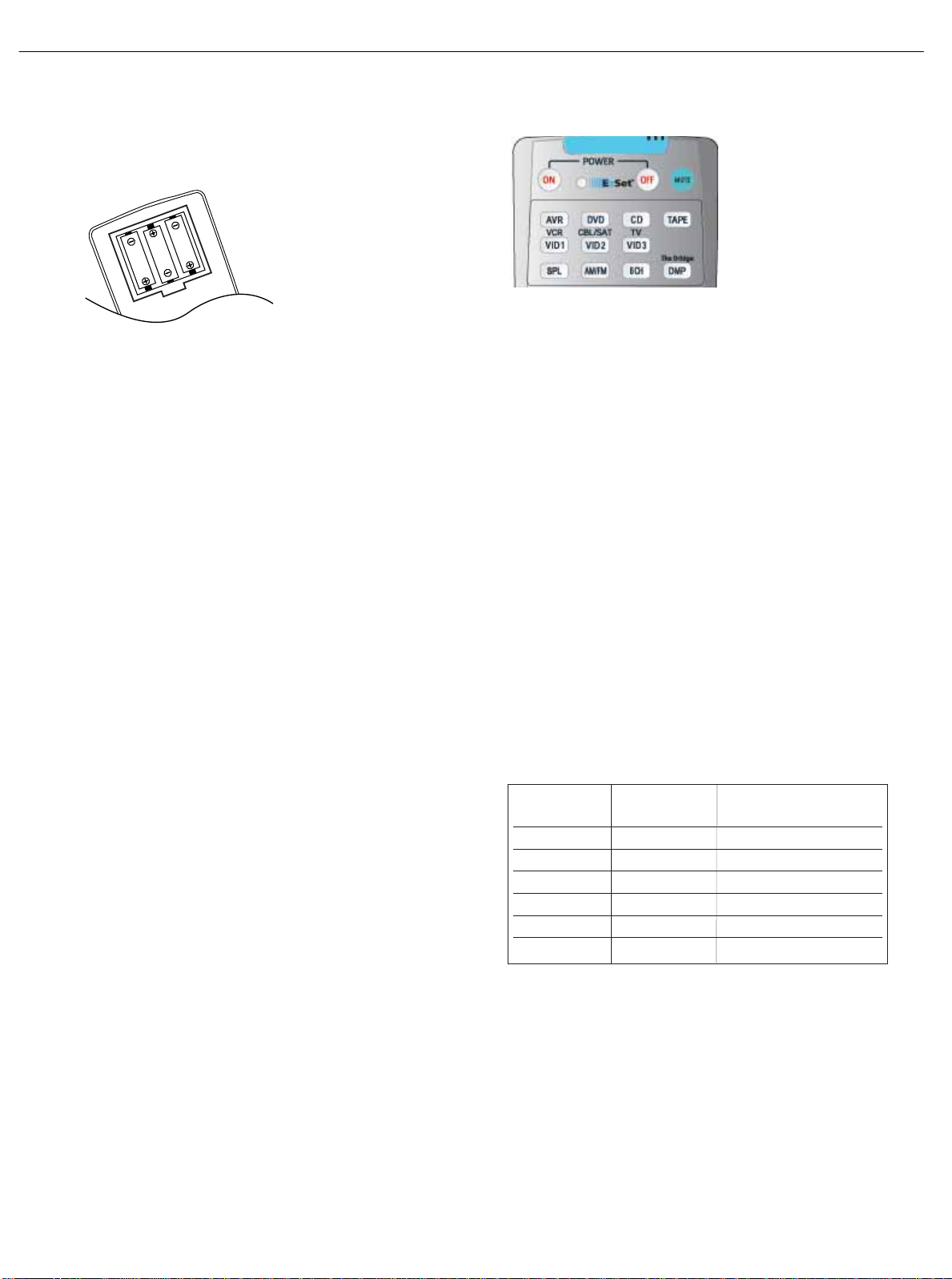
Insert the batteries as shown in the diagram, making sure to observe
the correct polarity.
Figure 29 – Remote Battery Compartment
When using the remote,remember to point the lens toward the front
panel of the AVR 145. Make sure no objects, such as furniture,are
blocking the remote’s path to the receiver. Bright lights,fluorescent lights
and plasma video displays may interfere with the remote’s functioning.
The remote has a range of about 20 feet, depending on the lighting
conditions.It may be used at an angle of up to 30 degrees to either
side of the AVR.
If the remote seems to operate intermittently, or if pressing a button
on the remote does not cause the AVR Selector or one of the Input
Selectors to light up,then make sure the batteries have been inserted
correctly, or replace all three batteries with fresh ones.
Step Eight – Program Sources Into the Remote
The AVR 145 remote is capable of controlling not only the receiver,
but it may also be programmed to control many brands and models of
VCRs,DVD players,CD players,cable boxes, satellite receivers,cassette
decks and TVs, as well as The Bridge.
It may help to think of the remote as a book with pages.Each page represents the button functions for a different device.In order to access the
functions for a particular device,you first need to turn to that page.This
is done by pressing the AVR Button to access the codes that control the
receiver, or the Input Selector buttons to access the codes for the
devices programmed into the remote.
At the factory,the AVR 145’s codes and the codes to control an iPod
docked in The Bridge are preprogrammed,and the codes for many
Harman Kardon DVD and CD players are also preprogrammed. If you
have other source devices in your system, follow these steps to program the correct codes into the remote.
1. Using the codes in Tables A9–A16 of the Appendix, look up the
product type (e.g. DVD,cable TV box) and the brand name of your
source.The number(s) listed are potential candidates for the correct
code set for your particular device.
2.Turn on your source device.
3. Put the remote into Program mode by pressing and holding the Input
Selector and the Mute button simultaneously until the LED on the
remote starts to flash, and then releasing the buttons.
Figure 30 – Input Selectors
4. Enter a code from Step 1 above.
a) If the device turns off, then press the Input Selector again to accept
the code,which will flash. The remote will exit the Program mode.
b) If the device does not turn off, tr y entering another code.If you run
out of codes,you may search through all of the codes in the
remote’s library for that product type by pressing the
⁄ or ¤
button repeatedly until the device turns off.When the device turns
off, enter the code by pressing the Input Selector,which will flash.
The remote then exits Program mode.
5. Once you have accepted a code,it’s a good idea to try using some
other functions to control the device.Sometimes manufacturers
use the same Power code for several different models, while other
codes will vary.You may wish to repeat this process until you’ve programmed a satisfactory code set that operates most of the functions
you frequently use.
6.You may find out which code number you have programmed by
pressing and holding the Input Selector and Mute Button simultaneously to enter the Program mode.Then press the Set Button, and the
LED will blink in the code sequence.One blink represents “1”, two
blinks for “2”,and so forth. A series of many fast blinks represents
“0”.Record the codes programmed for each device here.
Table 3 – Remote Control Codes
If you are unable to locate a code set that correctly operates your
source device,it will not be possible to use the AVR remote to control
that device.However,you may still connect the source to the AVR 145
and operate it using the device’s original remote control.Alternatively,
you may wish to consider purchasing Harman Kardon’s optional TC 30
activity-based remote,which is programmed by accessing a large database of product codes on the Internet.The TC 30 is also capable of
“learning” codes from your device’s original remote.
Source Input Product Type Remote Control Code
(circle one)
Video 1 VCR, PVR
Video 2 Cable,Satellite
Video 3 TV
DVD DVD
CD CD,CDR
Tape Cassette
20
AVR145
harman/kardon
Page 21
Most of the button labels on the remote describe the button’s function
when used to control the AVR 145. However,the button may perfor m a
very different function when used to control another device.Refer to the
Remote Control Function List,Table A8 in the Appendix, for a list of
each button’s functions with the various product types.
If you wish, you may program Macros,which are preprogrammed code
sequences that execute many code commands with a single button
press.You may also program “punch-through” codes,which allow the
remote to operate the volume,channel or transport controls of another
device without having to switch the remote to the mode for that device.
See pages 43 through 44 for instructions on these advanced programming functions.
NOTE: The AVR 145 remote is preprogrammed to operate the
transport controls of Harman Kardon DVD players when the AVR
or the Video 2 (cable/satellite) or Video 3 (TV) source is selected.
The volume and mute controls operate the AVR when any
device except Tape has been selected. You may change this
punch-through programming at any time.
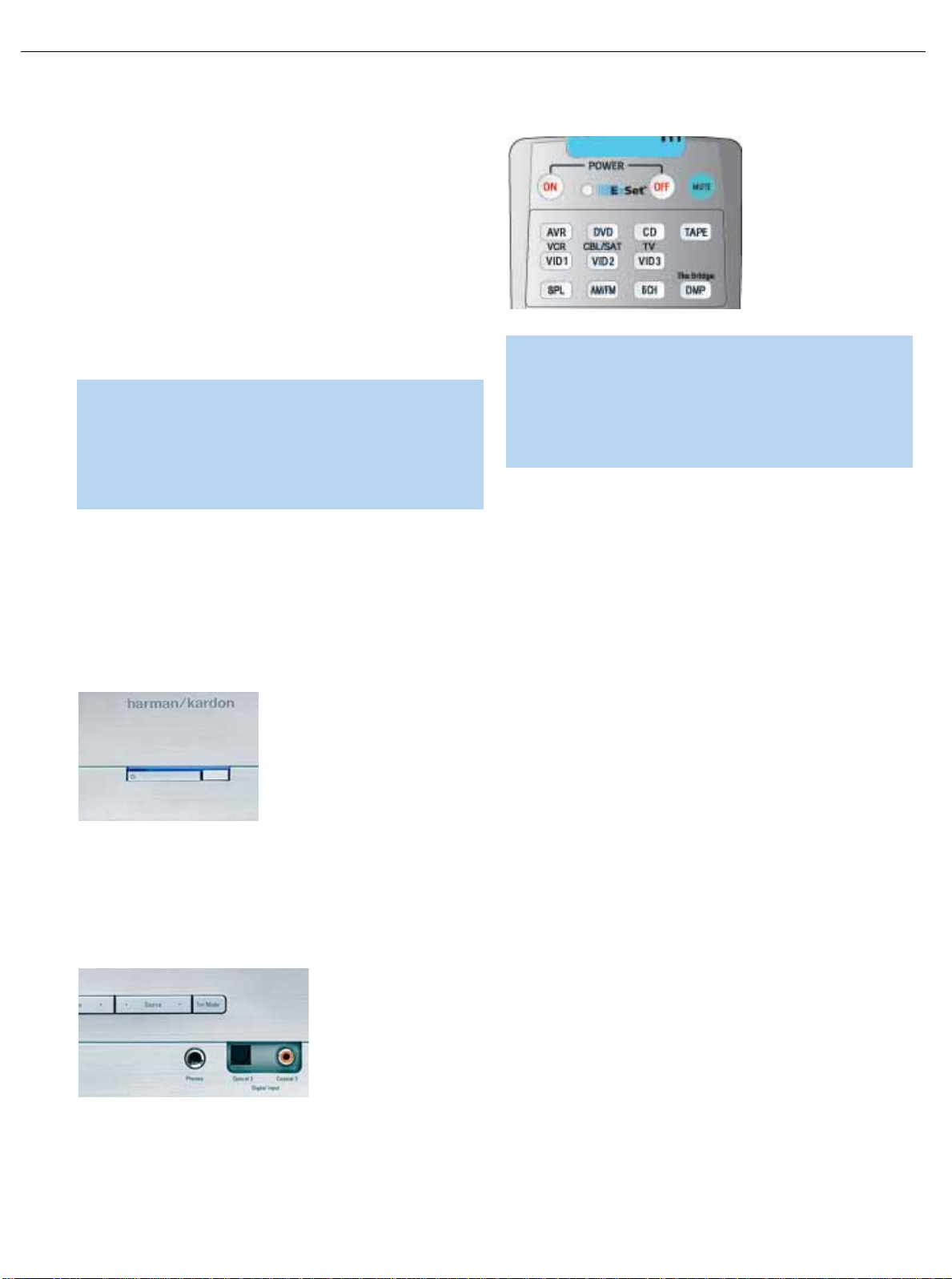
Step Nine – Turn On the AVR 145
Two steps are required the first time you turn on the AVR 145.
1. Gently press the Master Power Switch until the word OFF is no longer
visible.The Power Indicator above the two power switches should
light up in amber.This indicates that the AVR is in Standby mode and
is ready to be turned on. Normally,you may leave the Master Power
Switch in the ON position, even when the receiver is not being used.
Figure 31 – Power Switches
2.There are several ways in which the AVR 145 may be turned on from
Standby mode.
a) Press the Standby/On Switch on the front panel.
b) Press the Source Select Button on the front panel.
Figure 32 – Source Select Button
c) Using the remote,press any one of these buttons: AVR, DVD,CD,
TAPE,VID1,VID2, VID3, AM/FM or 6/8CH.
Figure 33 – AVRand Input Selectors
NOTE: Any time you press one of the Input Selectors on the
remote (i.e.,DVD,CD,TAPE,VID1, VID2 or VID3), the remote
will switch modes so that it will only transmit the codes programmed to operate that device.In order to control the receiver,
you will need to press the AVR button to return the remote to
AVR mode.
24
INSTALLATION
21
AVR145
harman/kardon
Page 22
31
OPERATION
Now that you have installed your system components and completed at
least a basic configuration of your receiver, you are ready to begin
enjoying your home theater system.
Turning On the AVR 145
Gently press the Master Power Switch until the word OFF is no longer visible.The Power Indicator above the two power switches should light up in
amber.This indicates that the AVR is in Standby mode and is ready to be
turned on. Normally,you may leave the Master Power Switch in the ON
position, even when the receiver is not being used.
Figure 44 – Power Switches
There are several ways in which the AVR 145 may be turned on:
a) Press the Standby/On Switch on the front panel.
b) Press the Source Select Button on the front panel.
Figure 45 – Source Select Button
c) Using the remote,press any one of these buttons: AVR,DVD, CD,
TAPE,VID1,VID2, VID3, AM/FM, 6/8CH or The Bridge/DMP.
Figure 46 – AVRand Input Selectors
NOTE: Any time you press one of the remote’s Input Selectors
(i.e.,DVD,CD,TAPE,VID1, VID2, VID3 or The Bridge/DMP),the
remote will switch modes so that it will only transmit the codes
programmed to operate that device.In order to control the
receiver, you will need to press the AVR Button to return the
remote to AVR mode.
To turn the receiver off, press either the Standby/On Switch on the front
panel, or press the AVR Button and the OFF Button on the remote.
Unless the receiver will not be used for an extended period of time (for
example,if you will be on vacation), it is not necessary to turn off the
Master Power Switch.When the Master Power Switch is turned off,any
settings you have programmed, including system configuration and preset radio stations,will be preserved for up to four weeks.
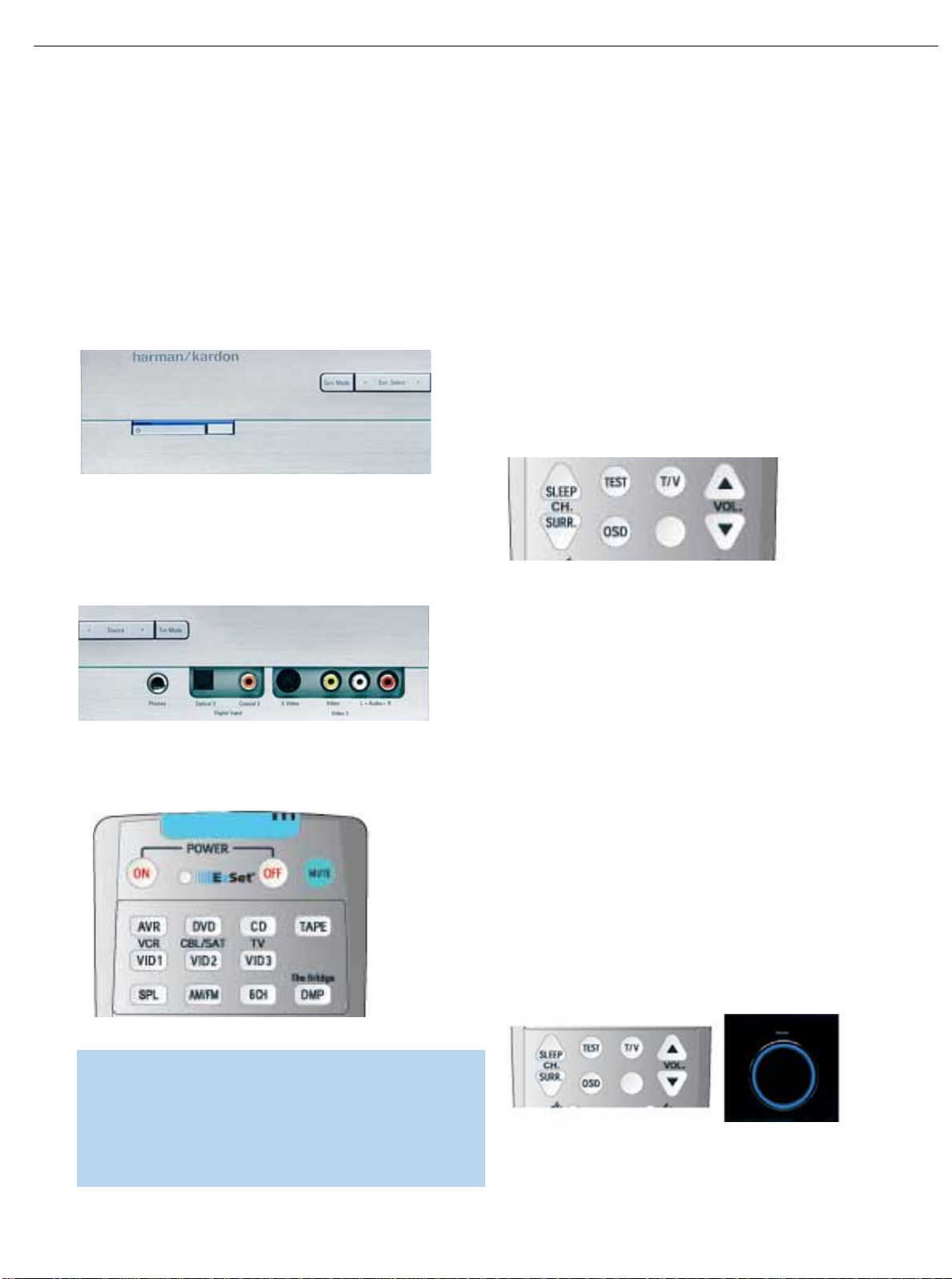
Sleep Timer
You may program the AVR to play for up to 90 minutes and then turn
off automatically using the sleep timer.
Press the Sleep Button on the remote,and the time until turn-off will be
displayed. Each additional press of the Sleep Button will reduce the time
until turn-off by 10 minutes,until the OFF setting is reached, which disables the sleep timer.
Figure 47 – Sleep Button
When the sleep timer has been set, the front-panel display will automatically dim to half-brightness.If you press any button on the remote or
front panel, the display will return to full-brightness.The display will dim
again several seconds after your last command.
If you press the Sleep Button after the timer has been set, the remaining
time until turn-off will be displayed.You may press the Sleep Button to
change the time until turn-off. Pressing and holding the Sleep Button will
disable the sleep timer, and the SLEEP OFF message will appear.
Volume Control
The volume may be adjusted either by turning the knob on the front
panel (clockwise to increase volume or counterclockwise to decrease
volume), or by pressing the Volume Control Buttons on the remote.The
volume is displayed as a negative number of decibels (dB) below the
0dB reference point, and may be changed in 0.5dB increments.Unlike
some volume controls on other products,0dB is the maximum volume
for the AVR 145. Although it’s physically possible to turn the volume to a
higher level, doing so may damage your hearing and your speakers.For
certain more-dynamic audio materials,even 0dB may be too high,
allowing for damage to equipment.
Figure 48 – Volume Controls
22
AVR145
harman/kardon
Page 23
32
OPERATION
Remember that the AVR 145 is designed to reproduce audio with a
minimum amount of distortion.This clarity may lead you to think that
your hearing and the equipment can handle higher volumes.We urge
caution with regard to volume levels.
Mute Function
To temporarily mute all speakers and the headphones,press the Mute
Button on the remote.Any recording in progress will not be affected.
The MUTE message will flash in the display as a reminder.To restore
normal audio,either press the Mute Button again, or adjust the volume.
Turning off the AVR will also end muting.
Figure 49 – Mute Button
Tone Controls
You may boost or cut either the treble or the bass frequencies by up
to 10dB in 2dB increments.
Using the front-panel controls or the remote,press the Tone Mode
Button once.This will indicate whether the tone controls are in or out
of the circuitry.If you wish to return the tone controls to 0, or “flat”
response,press the ‹/› Buttons until the TONE OUT message
appears,which preserves any changes you have made to the bass or
treble settings for later use.To reactivate your changes,the tone control
must again be set to TONEIN.
With the TONE IN message displayed,press the Tone Mode Button
repeatedly to access TREBLE MODE and BASS MODE.Use the ‹/›
Buttons to change the treble or bass settings,as desired. The display
will return to normal a few seconds after your last command.
Figure 50 – Tone Button
You may alternatively adjust the tone controls using the full-OSD menu
system. Press the OSD Button on the remote to view the Master Menu.
The cursor will be pointing to the INPUT SETUP line; press the Set
Button to display that menu.You will be able to view the tone settings.If
you wish to make any changes to the TONE,BASS or TREBLE settings,
use the arrow keys on the remote to move the cursor to the line you
wish to change.Once you have changed the setting using the ‹/›
Buttons,simply move the cursor up or down to a different line; it isn’t
necessary to press the Set Button to enter the new setting.When you
have finished, either wait until the display times out and disappears,
press the OSD Button to clear the display, or move the cursor to the
BACK TO MASTER MENU line if you wish to make other changes using
the menu system.
NOTE: The AVR 145 does not have any conventional balance
control.The EzSet process compensates for any characteristics
of your room or speakers,and we recommend that you leave
the settings as they are after EzSet has been run. However, you
may manually adjust the levels of the left and right channels –
decreasing one and increasing the other by the same amount –
using the Channel Adjust submenu,as described on page 41.
This achieves the same effect as a balance control.
Headphones
Plug the 1/4" plug on a pair of headphones into the headphone jack on
the front of the receiver for private listening.The first time you use the
headphones,the DOLBY H:BP message will be displayed, indicating that
Dolby Headphone surround processing is in the bypass mode,which
delivers a conventional 2-channel signal to the headphones.
Figure 51 – Headphone Jack
Press the Surround Select Button on the front panel, or the Dolby
Button on the remote,to switch to Dolby Headphone virtual surround
processing,indicated by the DOLBY H:DH message. Dolby Headphone
delivers an enhanced sound field that emulates a 5.1-channel speaker
system. No other surround modes are available for the headphones.
Source Selection
Press the front-panel Source Select Button to scroll through the
sources.The left side of the button scrolls down the list that appears in
the display; the right side scrolls upward. For direct access to the tuner,
press the Tuner Band Button, which switches to the last-used band and
frequency. For direct access to any source,press its Input Selector on
the remote (see Figure 46).
Figure 52 – Source Select and Tuner Band Buttons
NOTE: The Bridge/DMP source has no icon in the Source
Indicators display. When selected, the DMP indication will
appear in the message display’s upper line, and one of two
messages will scroll on the right side to indicate whether
The Bridge is unplugged or connected. If you have retitled this
source,then only the new name will appear in the upper line.
The AVR 145 will switch to the audio and video inputs assigned to that
source.If you set the BASS MGR setting in the Speaker X-over menu to
23
AVR145
harman/kardon
Page 24
33
OPERATION
INDEPENDENT, the AVR 145 will change the speaker size configuration
to the one you programmed for the source.If you selected a surround
mode for the source,the AVR 145 will switch to that mode.
The source name will appear in the upper line of the front-panel display.
If you retitled the source,only the new title will appear.Otherwise, the
audio input assigned to the source (analog or one of the digital audio
inputs) will also appear.The surround mode will be displayed on the
lower line.The same information will also appear on screen in the
semi-OSD, unless you have set the semi-OSD to OFF in the System
Setup menu.
Audio Input Selection
The AVR 145 is programmed at the factory to use the analog audio
inputs for each source (except for the DVD and Video 2 sources, which
default to Coax 1 and Optical 1).To assign a digital audio input to a
source (if you have not done so using the Input Setup menu during
Initial Setup), press the Digital Button on the remote or front panel. The
current audio input selection will flash in the display, and you may press
the
⁄/¤ (or ‹/› on the front panel) Buttons to scroll through the
audio inputs.When the desired input appears,press the Set Button to
select it.
Figure 53 – Digital Input Selection
If the Auto Poll feature has been left ON in the Input Setup menu,and if
a digital audio input has been assigned to the source,the AVR 145 will
first check the digital audio input for a signal. If a signal is present, the
AVR 145 will select the digital audio input.If no signal is present, the
AVR 145 will switch to the analog audio inputs for the source.
Video Input Selection
When a source is selected, the AVR 145 switches to a video input
as follows:
The COMPONENT IN line of the Input Setup menu indicates which
of the two component video inputs on the AVR 145 is assigned to
each source.All of the sources listed in the left column of the Source
Indicators display on the front panel are assigned to the Component
Video 2 inputs by default, and the sources listed in the right column
default to the Component Video 1 sources.This list appears in
Figure 54.
Figure 54 – Front-Panel Input Indicators
You may reassign either component video input to another source,but
there is no option to disable the component video inputs for any source.
If a signal is present at the component video input assigned to that
source,it will be selected. If your device is not using component video,
make sure that other devices connected to the component video inputs
are turned off.
If no signal is present at the component video input, then the S-video or
composite video input for the source will be selected. It is not possible
to reassign the S-video or composite video inputs to other sources.
For audio-only sources, such as the tuner or CD inputs, when no
component video signal is present, the last-used video source will be
selected.
6-Channel Direct Inputs
If you wish to hear audio through the 6-Channel Direct Inputs together
with video,then connect your multichannel player to the Component
Video 1 Inputs (the default for the 6-Channel Inputs), and the correct
audio and video inputs will be selected when you select 6CH as your
source.If your multichannel player uses S-video or composite video
connections,you will first need to select the source you connected the
video output to (e.g., DVD), and then select the 6CH source.
Figure 55 – 6-Channel Input Selector
NOTE: The 6-Channel Inputs pass the incoming signals directly
to the volume control, without digitizing or processing them.
Therefore,you will need to configure bass management settings
(i.e.,speaker size,delay and output level) on your source device
so that they match the settings you programmed using the
Manual Setup menu. Consult the owner’s guide for your multichannel player for more information.
Using the Tuner
The AVR 145’s built-in tuner may be selected in one of three ways:
1. Press the Source Selector Button on the front panel repeatedly until
the tuner is selected.The last-used band (AM or FM) will be active.
2. Press the Tuner Band Button (marked AM/FM).Press this button
again to switch bands.
3. Press the Tuner Input Selector (marked AM/FM) on the remote. Press
this button again to switch bands.
Figure 56 – Tuner Input Selection
24
AVR145
harman/kardon
DIGITAL LOGIC 7
PRO LOGIC
3 STEREO DSP
5 7 CH. STEREO
SURR. OFF
VID 1
VID 2
VID 3
DVD
CD
FMAM
TAPE
6 8 CH
Page 25
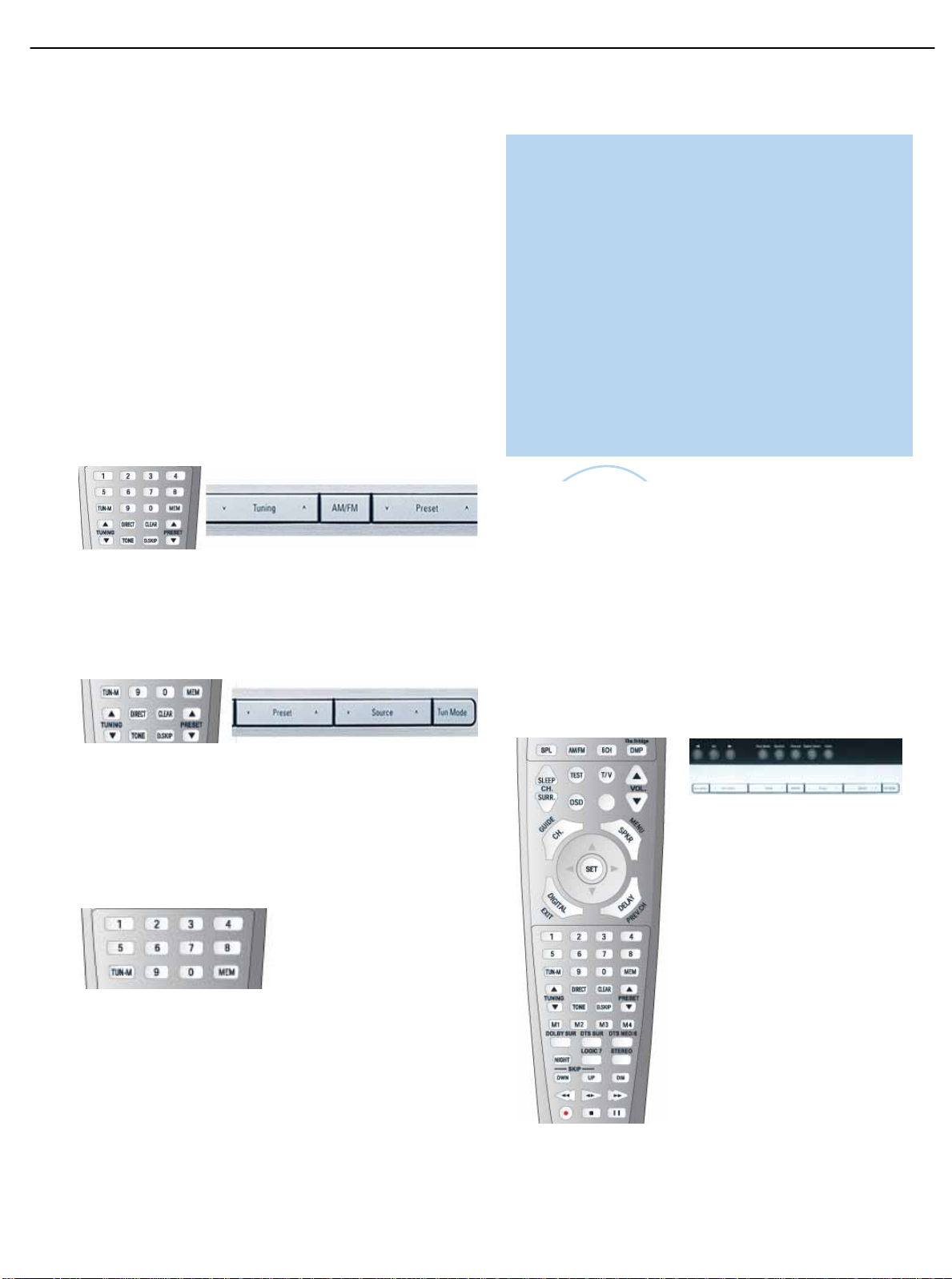
34
OPERATION
Radio stations may be selected in one of four ways:
1. If you know the frequency number, enter it directly by first pressing
the Direct Button on the remote,and then using the Numeric Keys.
2.After you have programmed Preset stations (see below), either enter
the Preset number (1 through 30) using the remote or use the frontpanel Preset Stations Button to scroll through the list of presets.
3. In Auto tuning mode, with each press of the Tuning Buttons (frontpanel or remote) the AVR 145 will scan in the chosen direction until a
station with acceptable signal strength is detected. Press the Tuning
Button again to stop scanning.
4. In Manual tuning mode,with each press of the Tuning Buttons the
AVR 145 will tune the next frequency increment (0.1MHz for FM,or
10kHz for AM) in the selected direction.Press and hold the Tuning
Button for faster scanning.
Figure 57 – Tuning a Station
Press the Tuning Mode Button (TUN-M on the remote) to switch
between Auto and Manual tuning modes.When an FM station has been
tuned, pressing the Tuning Mode Button will switch between stereo and
mono tuning,which may improve reception of weaker stations.
Figure 58 – Tuning Mode
To store a station in one of the 30 presets:
1.Tune the desired station.
2. Press the Memory Button on the remote.
3. Use the Numeric Keys to enter the desired preset number.
Figure 59 – Storing a Preset Station
Recording
Two-channel analog and digital audio signals,as well as composite
and S-video signals,are normally available at the appropriate recording
outputs.Thus,to make a recording, you need only make sure to connect your audio or video recorder to the appropriate output jacks,as
described in the Installation section, insert blank media and make sure
the recorder is turned on and recording while the source is playing.
NOTES:
1.Analog audio signals are not converted to digital form, and
digital audio signals are not converted to analog audio form.
However, you may record a coaxial or optical digital audio
source using either type of digital audio output.
2. Only PCM digital audio signals are available for recording.
Proprietary formats such as Dolby Digital and DTS may not
be recorded using the digital audio connections,although if
the source is connected to the AVR using the analog audio
connections,an analog recording may be made.
3. Component video sources are not available for recording.
4. Please make certain that you are aware of any copyright
restrictions on any material you record. Unauthorized duplication of copyrighted materials is prohibited by federal law.
Using
The Bridge is an optional dock that may be used with a compatible iPod
(not included).When The Bridge is connected to its proprietary input on
the AVR 145 and the iPod is docked, you may play the audio materials
on your iPod through your high-quality audio system,operate the iPod
using the AVR remote or the AVR’s front-panel controls,view navigation
messages on the AVR’s front panel or a connected video display, and
charge the iPod.
Either press the front-panel Source Selector repeatedly until the message “DMP/The Bridge is CONNECTED”scrolls across the front panel
and semi-OSD displays,or press the DMP Button on the remote to
select The Bridge as the input source.
(Left) Figure 60 – Using The Bridge (Remote)
(Above) Figure 61 – Using The Bridge (Front Panel)
25
AVR145
The
Bridge
TM
harman/kardon
Page 26

45
TROUBLESHOOTING GUIDE
SYMPTOM CAUSE SOLUTION
Unit does not function when Main • No AC Power • Make certain AC power cord is plugged into
Power Switch is pushed a live outlet
• Check to see whether outlet is switch-controlled
Display lights,but no sound • Intermittent input connections • Make certain that all input and speaker connections
or picture are secure
• Mute is on • Press Mute Button
• Volume control is down • Tur n up volume control
No sound from any speaker; • Amplifier is in protection mode • Check speaker wire connections for shorts at receiver and
light around power switch is red due to possible short speaker ends
• Amplifier is in protection mode • Contact your local Harman Kardon service center
due to internal problems
No sound from surround or • Incorrect surround mode • Select a mode other than Stereo
center speakers • Input is monaural • There is no surround information from mono sources
• Incorrect configuration • Check speaker mode configuration
• Stereo or Mono program material • The surround decoder may not create center- or rear-channel
information from nonencoded programs
Unit does not respond to • Weak batteries in remote • Change remote batteries
remote commands • Wrong device selected • Press the AVR selector
• Remote sensor is obscured • Make certain front panel sensor is visible to remote
or connect an optional remote sensor
Intermittent buzzing in tuner • Local interference • Move unit or antenna away from computers,fluorescent
lights,motors or other electrical appliances
Letters flash in the channel indicator • Digital audio feed paused • Resume play for DVD
display and digital audio stops • Check that Digital Input is selected
In addition to the items shown above,additional information on troubleshooting possible problems with your AVR 145,or installation-related issues,may
be found in the list of "Frequently Asked Questions" which is located in the Product Support section of our Web site at www.harmankardon.com.
26
AVR145
harman/kardon
Erasing Macros
It isn’t possible t o “ edit” a command within a macro. However, you m ay erase the m ac r o as follows:
1. Simultaneously pr ess and hold t he M ute Button and the Macro Button containing the macro until the LE D flashes.
2. Press the Surround But ton to erase the macro.
Resetting the Remote
To reset the remote t o its factory defaults, enter Program mode by simultaneously pressi ng and holding any Input Selector
and the Mute Button. When the LED flashes, enter the code “333”. W hen the LED goes out, the remote will have been
fully reset.
Processor Reset
There may be instances where you wish to fully reset the AVR 145 to its fac tory defaults, or the unit may behav e
erratically after a power surge.
For erratic behavior, we recommend you try turning the Master Power Switch off and unplugging the AC Power Cord for at
least three minutes. Try plugging the cord back in and turning the receiver back on. If this
doesn’t work, you may want t o try a system reset. NOTE: A system reset erases all user configurati ons, inc luding
speaker and level settings and tuner presets. Af ter a reset, you will need to re-enter all of t hese settings.
To reset the AVR 145, place the receiver in Standby mode (press the front -panel Standby/On Swit c h so that the Power
Indicator turns amber). Then press and hold the fr ont-panel Tone Mode Button for at least five
seconds until the RESET message appears in the display. If the r ec eiver still does not functi on c orrec tly after a processor
reset, contact an authorized Harman Kardon servi c e c enter for assistance.
Service centers may be loc ated by visiting our Web site at www.harmankar don.com.
Memory
If the AVR 145 is unplugged or ex peri enc es a power out age, it will retain user settings for up to four weeks.
Page 27
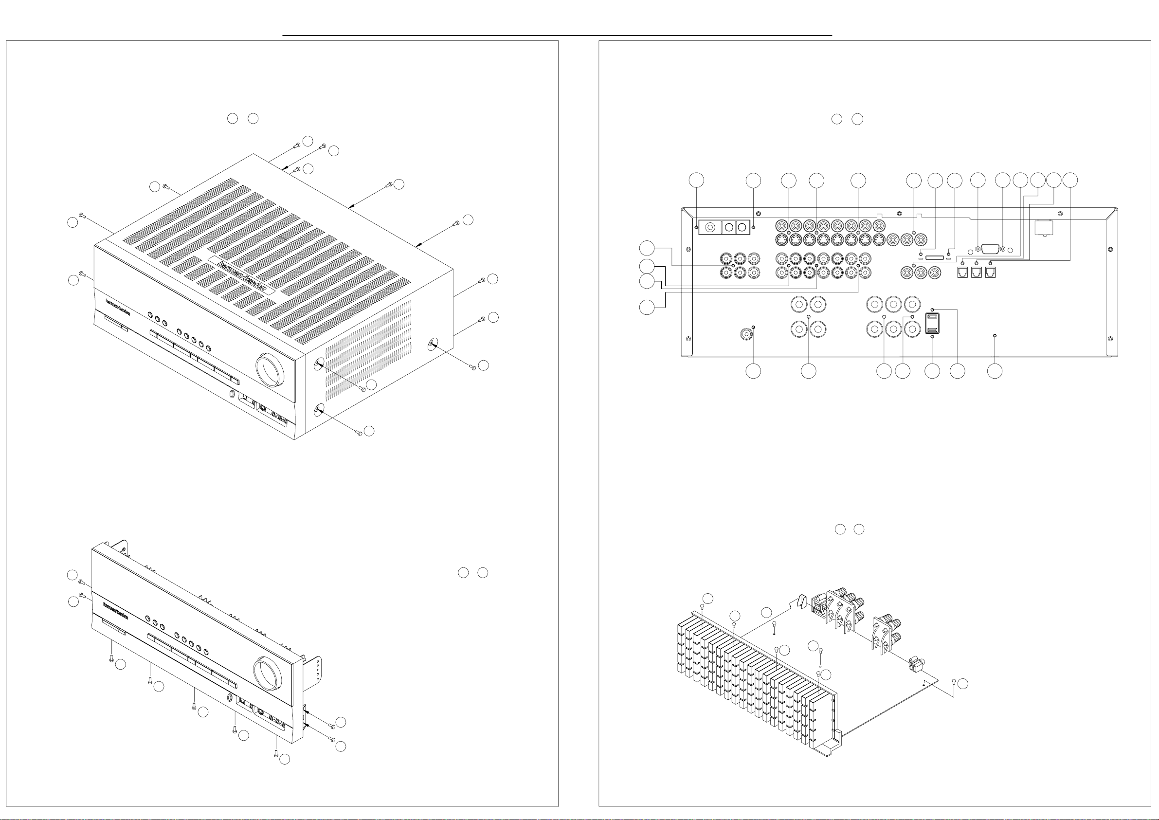
DISASSEMBLY
27
1. Removing the Top Cabinet
Remove the Screws
AVR145
13
1
~
6
10
9
11
7
3. Removing the Rear Panel
Remove the Screws
6
harman/kardon
5
4 3 2 1 11 12
AVR145
25
1
~
13
14
15
1816 17
4
5
1
2
8
7
8
12
13
3
9
10
19
20 21 22
23 24
25
4. Removing the Main PCB
1 7
Remove the Screws
~
2. Removing the Front Panel
9
8
7
6
5
4
Remove the Screws
1
2
3
1 9
~
1
2
5
6
3
4
7
Page 28

28
AVR145
harman/kardon
AVR145 DISASSEMBLY PROCEDURE
1 TOP-CABINET (21) REMOVAL
1. Remove 13 screws (S1,S7) and then remove the Top-cabinet.
2 FRO NT PANEL ASS’Y REMOVAL
1. Remove the Top-cabinet, referring to the previous step 1.
2. Disconnect the card cable between connector (CN72-17p) on the FIP PCB (37-1) and connector (CN72) on the Input PCB (39-1).
3. Disconnect the lead wire (BN81-8P) on the FIP PCB (37-1) from connector (CN81) on the Trans PCB (40-4).
4. Disconnect the lead wire (BN22-6P) on the Phone PCB (37-5) from connector (CN22) on the Input PCB (39-1).
5. Disconnect the lead wire (BN18-5P) on the Phone PCB (37-5) from connector (CN18) on the Input PCB (39-1)
6. Disconnect the lead wire (BN10-4P) on the Volume PCB (37-6) from connector (CN10) on the Input PCB (39-1)
7. Disconnect the lead wire (BN41-6P) on the Volume PCB (37-6) from connector (CN41) on the Video PCB (41)
8. Remove 1 screw (S10) and then lead wire (JW82-1P,JW83-1P) on the Phone PCB (37-5).
9 .Remove 1screw (S10) and then lead wire (JW84-1P) on the Volume PCB (37-3).
10. Remove 10 screws (S1) and then remove the Front Panel ASS’Y.
3 VOLUME PCB (37-6) REMOVAL
1. R emove the Top-cab inet , ref erring to the previous step 1.
2. Remove the Front Panel ASS’Y, referring to the previous step 2.
3. Pull out the Volume Knob ASS’Y.
4. Disconnect connector (CN84) on the Volume PCB (37-6) from the lead wire (BN84-5P) on the FIP PCB (37-1).
5. Remove 8 screws (S2,S14), and then remove the Volume PCB (37-6).
4 PHONE PCB (37-5) REMOVAL
1. R emove the Top-cab inet , ref erring to the previous step 1.
2. Remove the Front Panel ASS’Y, referring to the previous step 2.
3.. Disconnect connector (CN85)on the Phone PCB (37-5) from the lead wire (BN85-2P) on the FIP PCB (37-1).
4. Remove 2 screws (S2) and then remove the Phone PCB (37-5).
5 POWER LED PCB (37-3) REMOVAL
1. R emove the Top-cab inet , ref erring to the previous step 1.
2. Remove the Front Panel ASS’Y, referring to the previous step 2.
3. Disconnect connector (CN88) on the Power Led PCB (37-3) from the lead wire (BN88-4P) on the FIP PCB (37-1) .
4. Remove 2 screws (S2) and then remove the Power led PCB (37-3).
6 FIP PCB (37-1) REMOVAL
1. R emove the Top-cab inet , ref erring to the previous step 1.
2. Remove the Front Panel ASS’Y, referring to the previous step 2.
3. Disconnect the lead wire (BN84-5P) on the FIP PCB (37-1) from connector (CN84) on the Volume PCB (37-6).
4. Disconnect the lead wire (BN85-2P) on the FIP PCB (37-1) from connector (CN85) on the Phone PCB (37-5).
5. Disconnect the lead wire (BN88-4P) on the FIP PCB (37-1) from connector (CN88) on the Power Led PCB (37-3).
6. Disconnect the connector (CN89) on the FIP PCB (37-1) from lead wire (BN89-4P) on the Key PCB (37-2).
7. Remove 3 screws (S2) and then remove the Guide PCB (37-8) & the FIP PCB (37-1).
7 KEY PCB (37- 2) REMO VAL
1. R emove the Top-cab inet , ref erring to the previous step 1.
2. Remove the Front Panel ASS’Y, referring to the previous step 2.
3. Remove the FIP PCB (37-1), referring to the previous step6.
4. Remove 10 screws (S2) and then remove the Key PCB (37-2).
Page 29

29
AVR145
harman/kardon
8 T UNER MO DUL E (42) REMOVAL
1. Remove the Top-cabinet, referring to the previous step 1.
2. Disconnect the card cable between connector (CON1-13p) on the Tuner module (42) and connector (CN13) on Input PCB (39-1).
3. Remove 2 screws (S8) and then remove the Tuner Module (42).
9 VIDEO PCB (41) REMOVAL
1. Remove the Top-cabinet, referring to the previous step 1.
2. Disconnect the card cable between connector (BN14-13p) on the Video PCB (41) and connector (CN14) on the Input PCB (39-1).
3. Disconnect connector (CN43 ) on the Vide o PCB (41 ) from the lead wire (BN43-4P ) on the Re gulator PCB (A)(40 -2) .
4. Disconnect the card cable between connector (CN42) on the Video PCB (41) and connector (BN44-7p) on the I-Pod PCB (39-2).
5. Disconnect connector (CN41) on the Video PCB (41) from the lead wire (BN41-6P) on the Volume PCB (37-6).
6. Remove 6 screws (S8) and then remove the Video PCB (41).
10 I-POD PCB (39-2) REMOVAL
1. Remove the Top-cabinet, referring to the previous step 1.
2. Remove the Video PCB (41), referring to the previous step9
3. Disconnect connector (CN46) on the I-Pod PCB (39-2) from the lead wire (BN46-3P) on the Input PCB (39-1).
4. Disconnect the card cable between connector (BN19-9p)) on the I-Pod PCB (39-2) and connector (CN19) on the Input PCB (39-1).
5. Disconnect the card cable between connector (BN44-7p)) on the I-Pod PCB (39-2) and connector (CN42) on the Video PCB (41).
6. Disconnect the card cable between connector (CN47-7p)) on the I-Pod PCB (39-2) and connector (CN47) on the RS232 PCB (37-7).
7. Remove 2 screws (S13) and then remove the I-Pod PCB (39-2).
11 RS232 PCB (37-7) REMOVAL
1. Remove the Top-cabinet, referring to the previous step 1.
2. Remove the Video PCB (41), referring to the previous step9
3. Disconnect the card cable between connector (CN47) on the RS232 PCB (37-7) and connector (CN47-7) on the RS232 PCB (37-7).
4. Remove 2 screws and then remove the RS232 PCB (37-7).
12 INPUT PCB (39-1) REMOVAL
1. Remove the Top-cabinet, referring to the previous step 1.
2. Remove the Tuner module (42), referring to the previous step8
3. Remove the Video PCB (41), referring to the previous step9
4. Disconnect connector (CN20) on the the Input PCB (39-1) from the lead wire (BN20-5P) on the Regulator PCB (B)(40-5).
5. Disconnect connector (CN22) on the Input PCB (39-1) from the lead wire (BN22-6P) on the Phone PCB (37-5).
6. Disconnect connector (CN18) on the Input PCB (39-1) from the lead wire (BN18-5P) on the Phone PCB (37-5)
7. Disconnect connector (CN10) on the Input PCB (39-1) from the lead wire (BN10-4P) on the Volume PCB (37-6).
8. Disconnect the card cable between connector (CN14) on the Input PCB (39-1) and connector (BN14-13p)) on the Video PCB (41).
9. Disconnect the card cable between connector (CN19) on the Input PCB (39-1) and connector (BN19-9p) on the I-Pod PCB (39-2)
10. Disconnect the lead wire (BN46-3P) on the Input PCB (39-1) from connector (CN46) on the I-Pod PCB (39-2).
11. Disconnect the card cable between connector (CN12-21p) on the Input PCB (39-1) and connector (CN12-21p)
on the main PCB (38-1)
12. Disconnect the card cable between connector (CN11-13p) on the Input PCB (39-1) and connector (CN11) on the main PCB (38-1)
13. Disconnect the card cable between connector (CN72) on the Input PCB (39-1) and connector (CN72-17p) on the FIP PCB (37-1)
14. Remove 11 screws (S8,S15) and then remove the Input PCB (39-1).
13 POWER TRANS (36) & POWER PCB ASS’Y(40) REMOVAL
1. Remove the Top-cabinet, referring to the previous step 1.
2. Disconnect lead wire of the Power Trans (36) from connector (CN91-3P) on the Main PCB (38-1)
3. Disconnect connector (CN19-3P,CN20-4P) on TRANS PC B (40-3 ) from the lead wire (BN19-3P,BN20-4P) on the Main PCB (38-1).
4. Disconnect the lead wire (BN96-8P) on the Power PCB (40-4) from connector (CN96) on the Regulator PCB (B)(40-5).
5. Disconnect the lead wire (BN99-8P) on the Power PCB (40-4) from connector (CN99) on the Regulator PCB (A)(40-2).
6. Disconnect connector (CN81) on the Trans PCB (40-4) from the lead wire (BN81-8P) on the FIP PCB (37-1).
7. Remove 4 Trans screws (S9) and then remo v e th e Power Trans (36)& Power PCB ASS’Y(40) REMOVAL .
Page 30

30
AVR145
harman/kardon
14 MAIN PCB ASS’Y (38-1) REMOV AL
1. Remove the Top-cabinet, referring to the previous step 1.
2. Remove the Tuner module (42), referring to the previous step8.
3. Remove the Video PCB (41) referring to the previous step9.
4. Remove the I-Pod PCB (39-2), referring to the previous step 10.
5. Remove the RS232 PCB (37-7), referring to the previous step 11.
6. Remove the Input PCB (39-1), referring to the previous step 12.
7. Remove the AC Cord(35) on the Main PCB (38-1)
8. Disconnect the lead wire (BN90-2P) on the Main PCB (38-1) from connector (CN86) on Moms PCB (37-4).
9. Disconnect connector (CN91-3P) on the Main PCB (38-1) from lead wire of the Power Trans (36)
10. Disconnect the lead wire (BN89-2P) on the Main PCB (38-1) from connector (CN89) on Regulator PCB (A)(40-2).
11. Disconnect the lead wire (BN19-3P,BN20-4P) on the Main PCB (38-1) from connector (CN19-3P,CN20-4P) on TRANS PCB (40-4).
12. Remove 11screws (S13-1EA, S4-2EA, S6-2EA, S8-6EA) and then remove the Main PCB ASS’Y (38-1).
Page 31

31
AVR145
44
AVR145 EXPLODED VIEW
S9
40-4
36
S1
40-3
S16
40-1
S15
39-1
S16
S5
30
S4
40-2
45
S12
40-5
S17
29
harman/kardon
37-7
41
S6
x2
38-2
S4
38-1
35
33
34
S13
S13
39-2
S8
32
S10
42
S5
43
S5
28
22
21
S7
37-4
37-3
S2
37-1
37-8
S2
S2
S2
37-2
37-6
S11
23
S2
S4
15
13
14-1
14
S2
10
9
18
8
7
S10
23
S4
24
S2
37-5
37-9
19
26
25
24
LARGER PARTS
CHART NEXT PAGE
16
12
17
11
S2
10
S1
S1
6
5
4
DESCRIPTION PARTS NO. Q,ty
NO
S1
SCREW
S2
SCREW
S3
SCREW
S4
SCREW
S5
SCREW
S6
SCREW
S7
SCREW
S8
SCREW,TRANS
S9
SCREW
S10
SCREW
S11
SCREW CTB3+10JR 3
S12
SCREW
S13
SCREW,SPECIAL CHD1A012R 18
S14
SCREW,SPECIAL
S15
SCREW,SPECIAL
S16
SCREW,SPECIAL
S17
3
1
2
S5
S15
S14
40-2
S5
27
CTB3+10GR
CTWS3+10GR
CTW3+8JR
CTB3+8JR
CTW3+12JR
CTB4+6FFC
CTB3+10GFZR
CHD1A023R
CTB3+6JR
CTB3+16GFZR
CTB3+8JFZR
CHD1A012ZR 2
CHD3A012R 6
CHD4A012R 5
17CTB3+8JFCSCREW
35
1
9
10
3
6
19
4
19
2
3
DESCRIPTION
NO
ORNAMENT,VOLUME CGU1A318Z 1
1
CAP,VOLUME
2
HOLDER,VOLUME
3
INDICATOR,VOLUME
4
WINDOW ASS'Y
5
WINDOW,FIP CGU1A399Z
1
BADGE,MODEL
2
6
FILTER,FIP
7
BDAGE,HARMAN/KARDON
8
PANEL,FRONT
9
BRACKET,SIDE
10
KNOB,FUNCTION
11
KNOB,DISPLAY
12
KNOB,POWER
13
INDICATOR,POWER
14
KNOB,MOMS
15
BRACKET,PCB CMK2A010
16
PLATE,SHIELD
17
SHEET , REFLECTION CMZ1A120 1
18
HOLDER,LED
19
BRACKET,FIP
20
CABINET,TOP
21
CHASSIS,BOTTOM
22
RUBBER,CUSHION
23
FOOT
24
SUPPORT,CUSHION
25
HEAT SINK
26
BRACKET,PCB
27
HOLDER,PCB
28
BRACKET,TRANS
29
BRACKET,PCB(H/T)
30
BRACKET,PCB CMD1A570 1
31
BRACKET,PCB
32
PANEL,REAR
33
BUSHING,AC CORD
34
CORD,POWER
35
TRANS,POWER
36
FRONT PAB ASS'Y
37
MAIN PCB ASS'Y COP11911B 1
38
INPUT PCB ASS'Y COP11912B 1
39
POWER PCB ASS'Y
40
VIDEO PCB ASS'Y
41
TUNER MODULE
42
43
BADGE ASS'Y
44
ORNAMENT,BADGE
1
BADGE,H/K(TOP)
2
45
PARTS NO.
CGX1A338MBC63
CMH1A214
CGL1A222
CGUAVR145
CGB1A168Z
CMZ2A090SHEET,VOLUME 1
CMZ1A088
KGB1A158Z
CGW1A427RDZH43
CMD2A443
CBT1A1028MBZG27
CBT1A1027K128
CBT1A1026MMZG27
CGL1A258Z
CBC1A158MBZG27
CMC1A302
CMH1A215
CMD1A209
CKC5B145S46Z
CUA2A229
CHG1A329
CKL2A069H43
CHG1A104Z
CMY1A269
CMD1A417
CHE1A170
CMD1A487
CMD1A398
CMD1A387
CKF1A319Z
KHR1A028
CJA523FBYA
COP11910B
37-1
37-2
37-3
37-4
37-5
37-6
37-7
37-8
38-1
38-2
39-1
39-2
COP11916B 1
40-1
40-2
40-3
40-4
40-5
COP11917B 1
CNVM9011MS071L
CHG1A160ZCUSHION 1
CGX1A375ZA
CGX1A375M7G32
KGB1A159Z
CMY1A249HEAT SINK 1
S4
FIP PCB
KEY PCB
POWER LED PCB
MOMS PCB
PHONE PCB
VOLUME PCB
RS232 PCB
GUIDE PCB(CARD CABLE)
MAIN PCB
GUIDE PCB(CARD CABLE) 1
INPUT PCB
ipod PCB 1
DIGITAL IN OUT PCB 1
REGULATOR PCB(A) 5
TRANS PCB 1
TRANS PAC 1
REGELATOR PCB(B) 1
Weright
Q,ty
1
1
1
1
1
1
1
1
1
2
11
1
1
1
1
1
1
3
1
1
4
4
1
1
2
2
1
2
2
1
1
1
1
1
1
1
1
1
1
1
1
1
1
1
1
1
1
1
1
Page 32

32
AVR145
harman/kardon
Page 33
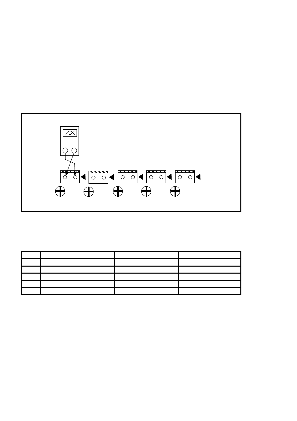
C
C
C
C
33
AVR145
AMPLIFIER SECTION BIAS ADJUSTMENT
Measurement condition
.No input signal or volume position is minimum.
Standard value
.Ideal current = 48mA (± 5%)
.Ideal DC Voltage = 25.92mV (± 5%)
DC EVM
CUP11911Y (MAIN PCB)
harman/kardon
N61
VR32
DC VOLTMETER ; Connect to
CN66(SL),CN61(CEN),CN64(SR),CN63(FL),CN65(SBL/SL(AVR132,144,145)),CN62(FR),CN67(SBR)
NO.
1
2
3
4
5
Channel
Front Left
Front Right
Center
Surround Left
Surround Right
VR33
CN64
N63
VR34
25.92mV (± 5%)
25.92mV (± 5%)
25.92mV (± 5%)
25.92mV (± 5%)
25.92mV (± 5%)
VR35
Adjust for Adjustment
N65
N62
VR36
CN63
CN62
CN61
CN65
CN64
Page 34

34
AVR145
harman/kardon
Page 35

35
AVR145
harman/kardon
Page 36
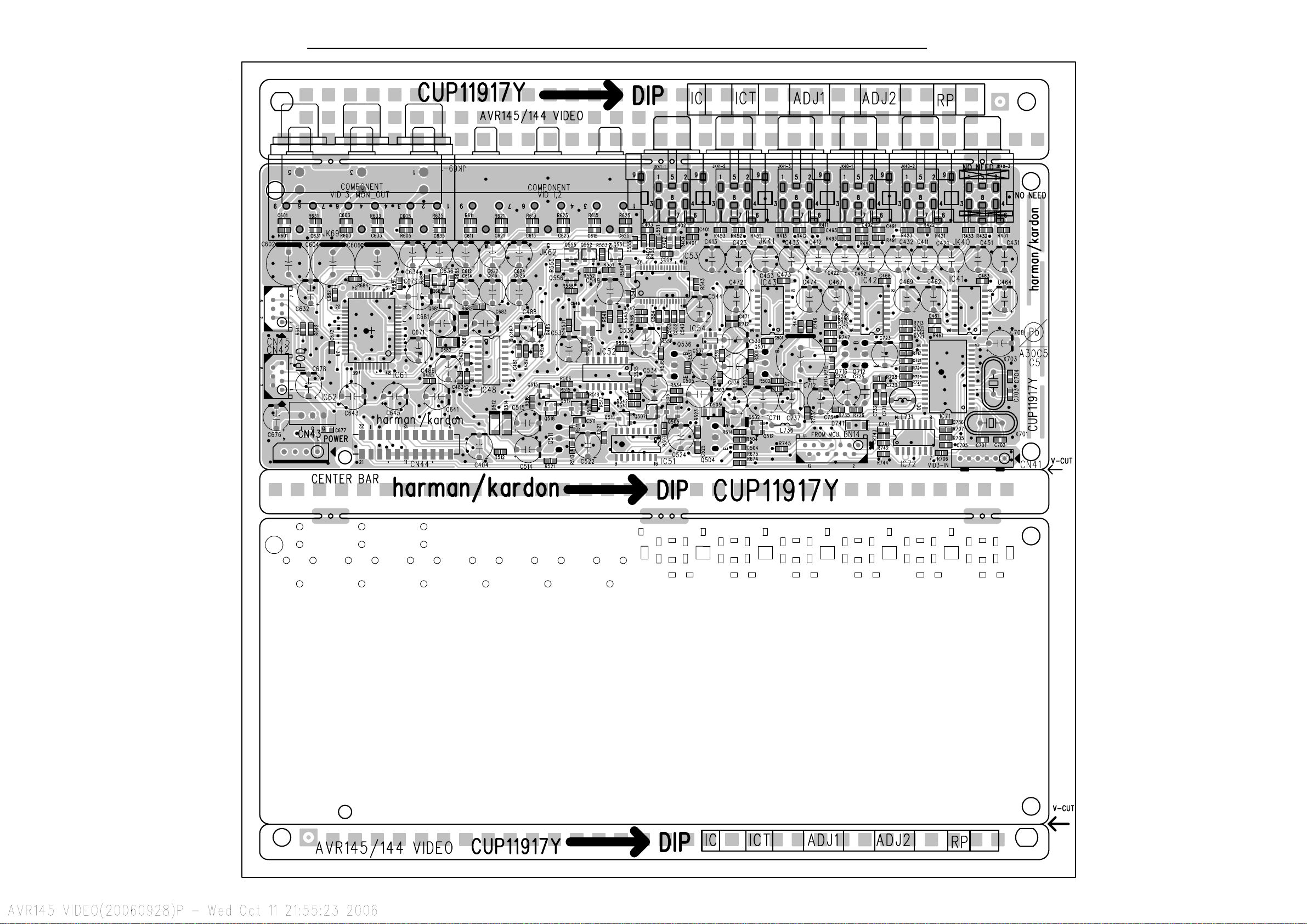
36
AVR145
harman/kardon
Page 37
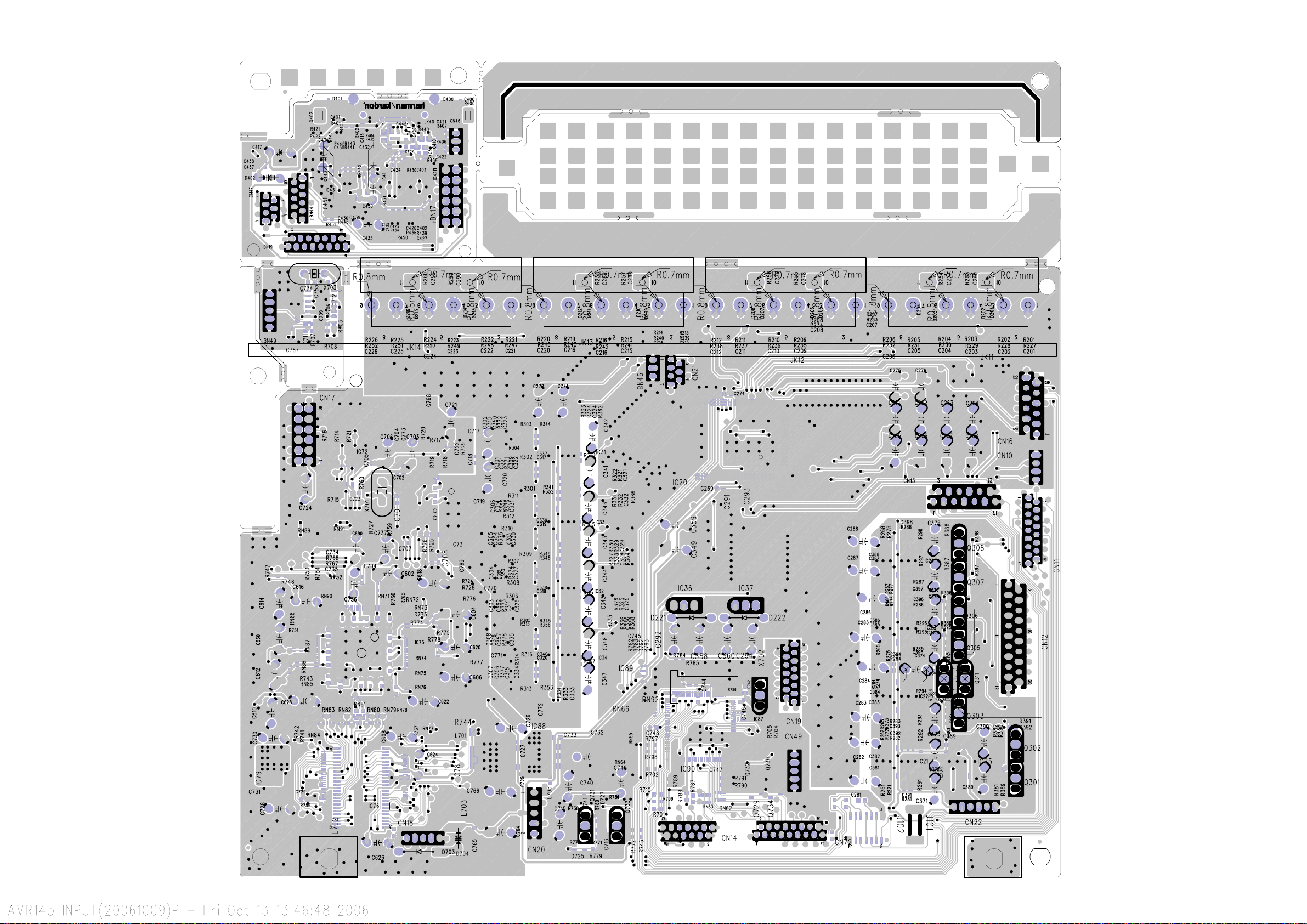
37
AVR145
harman/kardon
Page 38
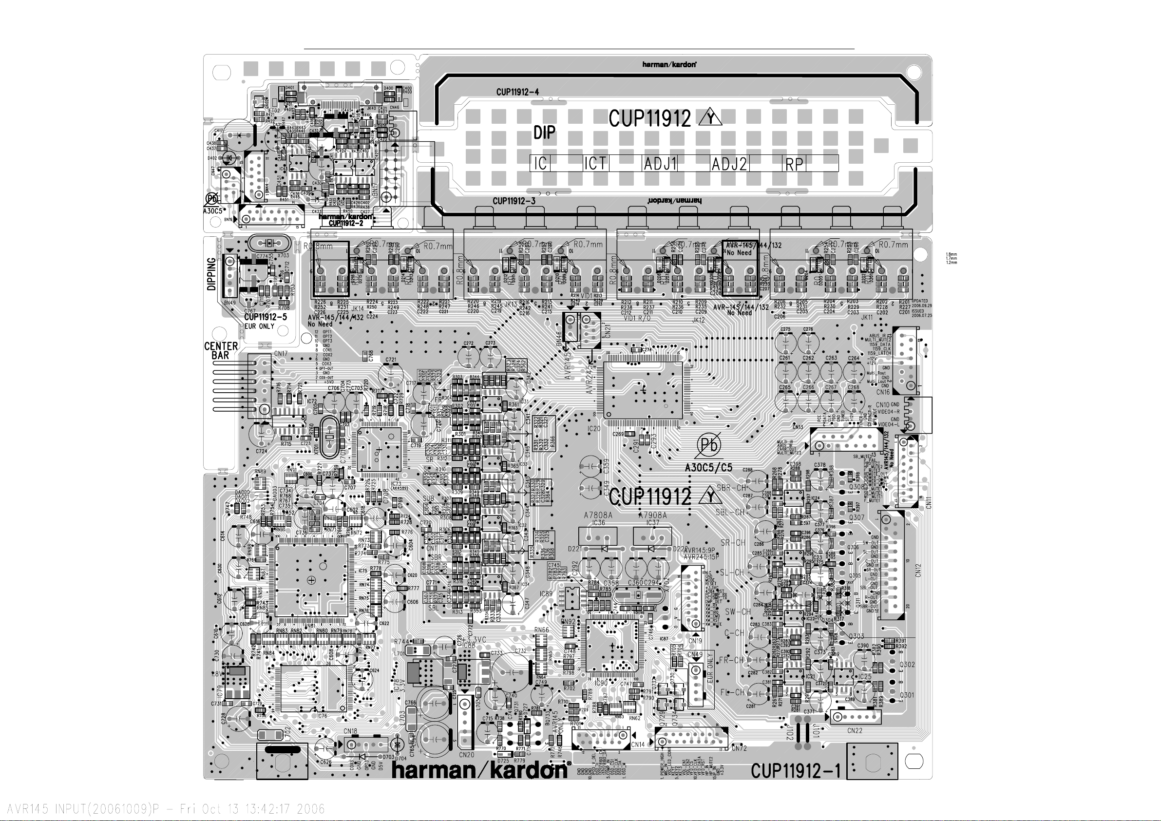
38
AVR145
harman/kardon
Page 39

39
AVR145
harman/kardon
Page 40

40
AVR145
harman/kardon
Page 41

41
AVR145
harman/kardon
Page 42

42
AVR145
AVR145 Electrical Parts List
Ref. Designator Part Number
Description
Qty
FRONT PCB ASSY CUP11910-1
Capacitors
C714 HCBS1H151KBT CAP , CERAMIC 150UF 50V K 1
C716 CCEA1AH331T CAP , ELECT 330UF 10V 1
C723 HCBS1H104ZFT CAP , CERAMIC 0.1UF 50V Z 1
C728 HCBS1H104ZFT CAP , CERAMIC 0.1UF 50V Z 1
C729 HCBS1H473ZFT CAP , CERAMIC 0.047UF 50V Z 1
C731 CCEA1HH100T CAP , ELECT 10UF 50V 1
C735 CCEA1CKS100T CAP , ELECT 10UF 16V 1
C742 HCBS1H223ZFT CAP , CERAMIC 0.02UF 50V Z 1
C793 HCBS1H104ZFT CAP , CERAMIC 0.1UF 50V Z 1
C794 HCBS1C222MXT CAP , CERAMIC 2200PF 16V 1
C795 HCBS1H102KBT CAP , CERAMIC 1000PF 50V K 1
C796 HCBS1H102KBT CAP , CERAMIC 1000PF 50V K 1
C882 HCBS1H104ZFT CAP , CERAMIC 0.1UF 50V Z 1
C891 HCBS1H223ZFT CAP , CERAMIC 0.023UF 50V Z 1
C892 HCBS1H223ZFT CAP , CERAMIC 0.023UF 50V Z 1
C893 HCBS1H223ZFT CAP , CERAMIC 0.023UF 50V Z 1
C894 CCEA1CKS100T CAP , ELECT 100UF 16V 1
C896 HCBS1H223ZFT CAP , CERAMIC 0.023UF 50V Z 1
C897 CCEA1AH471T CAP , ELECT 470UF 10V 1
C901 HCBS1H390JT CAP , CERAMIC 39PF 50V Z 1
C903 CCEA1HKS2R2T CAP , ELECT 2.2UF 50V SMALL SIZE 1
C905 CCEA1HKS2R2T CAP , ELECT 2.2UF 50V SMALL SIZE 1
harman/kardon
Semiconductors
D730 CVD1SS133MT DIODE 1SS133 1
D778 HVD1N5819T DIODE , SCHOTTKY 1N5819 1
IC73 HRVNJL34H380A SENSOR , REMOTE SENSOR 1
IC75 HVI74ACT04MTR I.C , HEX FAIRCHILD 1
Q701 HVTKRC107MT TRANSISTOR NPN KRC107M 1
Q722 HVTKRA107MT TRANSISTOR PNP KRA107M 1
Q724 HVTKRC107MT TRANSISTOR NPN KRC107M 1
Q725 HVTKRC107MT TRANSISTOR NPN KRC107M 1
Q738 HVTKRC107MT TRANSISTOR PNP KRC107M 1
Q739 HVTKTA1271YT TRANSISTOR PNP KTA1271Y 1
Resistors
R701 CRD20TJ103T RES , CARBON 10K OHM 1/5W J 1
R704 CRD20TJ100T RES , CARBON 10 OHM 1/5W J 1
R709 CRD20TJ470T RES , CARBON 47 OHM 1/5W J 1
R710 CRD20TJ470T RES , CARBON 47 OHM 1/5W J 1
R711 CRD20TJ470T RES , CARBON 47 OHM 1/5W J 1
R718 CRD20TJ222T RES , CARBON 2.2K OHM 1/5W J 1
R737 CRD20TJ100T RES , CARBON 10 OHM 1/5W J 1
R747 CRD20TJ103T RES , CARBON 10K OHM 1/5W J 1
R781 CRD20TJ102T RES , CARBON 1K OHM 1/5W J 1
R783 CRD20TJ102T RES , CARBON 1K OHM 1/5W J 1
R784 CRD20TJ102T RES , CARBON 1K OHM 1/5W J 1
R786 CRD20TJ152T RES , CARBON 1.5K OHM 1/5W J 1
R787 CRD20TJ101T RES , CARBON 100 OHM 1/5W J 1
R791 CRD20TJ822T RES , CARBON 8.2K OHM 1/5W J 1
R892 CRD20TJ222T RES , CARBON 2.2K OHM 1/5W J 1
R893 CRD20TJ333T RES , CARBON 33K OHM 1/5W J 1
R913 CRD20TJ102T RES , CARBON 1K OHM 1/5W J 1
R915 CRD20TJ473T RES , CARBON 47K OHM 1/5W J 1
Page 43

43
AVR145
Ref. Designator Part Number
FRONT PCB ASSY CUP11910-1
Miscellaneous
L702 HLQ02C100KT COIL , AXAIL COIL 1
FIP1 HFLHCA18ML03 F.I.P F.I.P 1
CN72 CJP17GA193ZY WAFER, CARD CABLE (SMD) WAFER 1
CN89 CJP04GB46ZY WAFER WAFER 1
BN81 CWB2C908200BM WIRE ASS'Y WIRE 1
BN84 CWB2B905080EN WIRE ASS'Y WIRE 1
BN85 CWB2B902100EW WIRE ASS'Y ( ANGLE ) WIRE 1
BN88 CWB2B904100EN WIRE ASS'Y WIRE 1
CMC3A111 PLATE , EARTH PLATE 1
Description
PCB , FRONT STAND BY CUP11910-3
CN88 CJP04GB46ZY WAFER WAFER 1
R824 CRD20TJ221T RES , CARBON 220 OHM 1/5W J 1
R825 CRD20TJ681T RES , CARBON 680 OHM 1/5W J 1
R828 CRD20TJ221T RES , CARBON 220 OHM 1/5W J 1
R829 CRD20TJ681T RES , CARBON 680 OHM 1/5W J 1
S701 HST1A020ZT SW , TACT 1A020 1
D723 CVD50BOBBWGA L.E.D , 2 COLOR (ORG , BLUE) L.E.D 1
D727 CVD50BOBBWGA L.E.D , 2 COLOR (ORG , BLUE) L.E.D 1
Qty
harman/kardon
PCB , FRONT POWER (MOMS) SW CUP11910-4
CN86 CJP02GA89ZM WAFER WAFER 1
SW1 CSH1A008ZV SW , PUSH (MOMS) MOMS SWITCH 1
PCB , DOWNLOAD JACK CUP11910-7
CN47 CJP07GA117ZY TEMP ITEM WAFER 1
IC97 HVIST202EBW IC , RS232C ST 1
JK97 CJJ9W001Z 9P D-SUB FEMALE(RS-232C) JACK 1
SW95 KST1A010Z SW , TACT SWITCH 1
SW96 HSH2B018Z SW , PUSH SWITCH 1
R956 CRD20TJ1R0T RES , CARBON 1 OHM 1/5W J 1
C953 HCBS1H104ZFT CAP , CERAMIC 0.1UF 50V Z 1
C954 HCBS1H104ZFT CAP , CERAMIC 0.1UF 50V Z 1
C957 HCBS1H104ZFT CAP , CERAMIC 0.1UF 50V Z 1
PCB , FRONT PANEL KEY CUP11910-2
Capacitors
C719 HCBS1H102KBT CAP , CERAMIC 1000PF 50V K 1
C720 HCBS1H102KBT CAP , CERAMIC 1000PF 50V K 1
C721 HCBS1H102KBT CAP , CERAMIC 1000PF 50V K 1
Resistors
R753 CRD20TF1001T RES , CARBON 1K /1/5W /F 1
R754 CRD20TF1501T RES , CARBON 1.5K /1/5W /F 1
R755 CRD20TF1801T RES , CARBON 1.8K /1/5W /F 1
R756 CRD20TF2701T RES , CARBON 2.7K /1/5W/F 1
R757 CRD20TF3301T RES ,CARBON 3.3K /1/5W/F 1
R758 CRD20TF5601T RES ,CARBON(5.6K/F) 5.6K/1/5W/F 1
R759 CRD20TF1001T RES , CARBON 1K /1/5W /F 1
R760 CRD20TF1501T RES , CARBON 1.5K /1/5W /F 1
R761 CRD20TF1801T RES , CARBON 1.8K /1/5W /F 1
R762 CRD20TF2701T RES , CARBON 2.7K /1/5W/F 1
R763 CRD20TF3301T RES ,CARBON 3.3K /1/5W/F 1
Page 44

44
AVR145
Ref. Designator Part Number
Description
Qty
PCB , FRONT PANEL KEY CUP11910-2
R764 CRD20TF5601T RES ,CARBON(5.6K/F) 5.6K/1/5W/F 1
R765 CRD20TF7501T RES , CARBON (7.5K/F) 7.5K/1/5W/F 1
R766 CRD20TF1001T RES , CARBON 1K /1/5W /F 1
R767 CRD20TF1501T RES , CARBON 1.5K /1/5W /F 1
R768 CRD20TF1801T RES , CARBON 1.8K /1/5W /F 1
R769 CRD20TF2701T RES , CARBON 2.7K /1/5W/F 1
Miscellaneous
S702 HST1A020ZT SW , TACT 1A020 1
S703 HST1A020ZT SW , TACT 1A020 1
S704 HST1A020ZT SW , TACT 1A020 1
S705 HST1A020ZT SW , TACT 1A020 1
S706 HST1A020ZT SW , TACT 1A020 1
S707 HST1A020ZT SW , TACT 1A020 1
S708 HST1A020ZT SW , TACT 1A020 1
S709 HST1A020ZT SW , TACT 1A020 1
S710 HST1A020ZT SW , TACT 1A020 1
S711 HST1A020ZT SW , TACT 1A020 1
S712 HST1A020ZT SW , TACT 1A020 1
S713 HST1A020ZT SW , TACT 1A020 1
S714 HST1A020ZT SW , TACT 1A020 1
S715 HST1A020ZT SW , TACT 1A020 1
S716 HST1A020ZT SW , TACT 1A020 1
S717 HST1A020ZT SW , TACT 1A020 1
S718 HST1A020ZT SW , TACT 1A020 1
S719 HST1A020ZT SW , TACT 1A020 1
S720 HST1A020ZT SW , TACT 1A020 1
BN89 CWB2B904100EN WIRE ASS'Y WIRE 1
harman/kardon
PCB , VR JACK CUP11910-6
Capacitors
C805 HCBS1H223ZFT CAP , CERAMIC 0.022UF 50V Z 1
C806 HCBS1H223ZFT CAP , CERAMIC 0.022UF 50V Z 1
C841 CCEA1HH100T CAP , ELECT 10UF 50V 1
C842 CCEA1HH100T CAP , ELECT 10UF 50V 1
C843 CCEA1HH100T CAP , ELECT 10UF 50V 1
C855 HCBS1H101KBT CAP , CERAMIC 100PF 50V K 1
C856 HCBS1H101KBT CAP , CERAMIC 100PF 50V K 1
C857 HCBS1H104ZFT CAP , CERAMIC 0.1UF 50V Z 1
C862 HCBS1H101KBT CAP , CERAMIC 100PF 50V K 1
C863 HCBS1H101KBT CAP , CERAMIC 100PF 50V K 1
C874 HCBS1H101KBT CAP , CERAMIC 100PF 50V K 1
Semiconductors
D774 CVD1SS133MT DIODE 1SS133 1
D701 CVD52CSBBCEAB2 BLUE L.E.D L.E.D 1
D703 CVD52CSBBCEAB2 BLUE L.E.D L.E.D 1
D705 CVD52CSBBCEAB2 BLUE L.E.D L.E.D 1
Resistors
R705 CRD20TJ820T RES , CARBON 82 OHM 1/5W J 1
R706 CRD20TJ820T RES , CARBON 82 OHM 1/5W J 1
R708 CRD20TJ820T RES , CARBON 82 OHM 1/5W J 1
R864 CRD20TJ272T RES , CARBON 2.7K OHM 1/5W J 1
R865 CRD20TJ101T RES , CARBON 100 OHM 1/5W J 1
R866 CRD20TJ272T RES , CARBON 2.7K OHM 1/5W J 1
Page 45

45
AVR145
Ref. Designator Part Number
Description
Qty
PCB , VR JACK CUP11910-6
R871 CRD20TJ104T RES , CARBON 100K OHM 1/5W J 1
R872 CRD20TJ104T RES , CARBON 100K OHM 1/5W J 1
R873 CRD20TJ471T RES , CARBON 470 OHM 1/5W J 1
R874 CRD20TJ471T RES , CARBON 470 OHM 1/5W J 1
R876 CRD20TJ750T RES , CARBON 75 OHM 1/5W J 1
R877 CRD20TJ750T RES , CARBON 75 OHM 1/5W J 1
R878 CRD20TJ750T RES , CARBON 75 OHM 1/5W J 1
R881 C3A206 WIRE , COPPER SN95/PB5 , 0.6
R882 C3A206 WIRE , COPPER SN95/PB5 , 0.6
VR74 CSR2A037Z ENCODER ENCODER 1
Miscellaneous
CN84 CJP05GB46ZY WAFER WAFER 1
BN10 CWZAVR230BN10 WIRE ASS'Y (SHIELD) WIRE 1
BN41 CWZAVR130BN41 WIRE ASS'Y (SHIELD) WIRE 1
JK85 CJJ9M003Z JACK , S-VIDEO S-VIDEO JACK 1
JK86 CJJ4S023Y JACK , BOARD BOARD 1
JW84 CWE8202110RV WIRE ASS'Y WIRE 1
harman/kardon
PCB , PHONE JACK CUP11910-5
Capacitors
C807 HCBS1H104ZFT CAP , CERAMIC 0.1UF 50V Z 1
C808 HCBS1H181KBT CAP , CERAMIC 180PF 50V Z 1
C809 CCEA1AH471T CAP , ELECT 470UF 10V 1
C812 HCBS1H104ZFT CAP , CERAMIC 0.1UF 50V Z 1
C817 HCBS1H100JCT CAP , CERAMIC 10PF 50V 1
C850 HCBS1H471KBT CAP , CERAMIC 470PF 50V 1
C851 HCBS1H471KBT CAP , CERAMIC 470PF 50V 1
C852 HCBS1H104ZFT CAP , CERAMIC 0.1UF 50V Z 1
C866 CCEA1HKS100T CAP , ELECT 10UF 50V 1
C867 CCEA1HKS100T CAP , ELECT 10UF 50V 1
C868 CCEA1EKS470T CAP , ELECT 47UF 25V 1
C869 CCEA1EKS470T CAP , ELECT 47UF 25V 1
C870 HCBS1H681KBT CAP , CERAMIC 680PF 50V K 1
C871 HCBS1H681KBT CAP , CERAMIC 680PF 50V K 1
C872 CCEA1CH331T CAP , ELECT 330UF 16V 1
C873 CCEA1CH331T CAP , ELECT 330UF 16V 1
C889 HCBS1H104ZFT CAP , CERAMIC 0.1UF 50V Z 1
Semiconductors
D784 CVD1SS133MT DIODE 1SS133 1
D785 CVD1SS133MT DIODE 1SS133 1
Q734 HVTKTC2874BT TRANSISTOR , MUTE NPN KTC2874B 1
Q735 HVTKTC2874BT TRANSISTOR , MUTE NPN KTC2874B 1
Q736 HVTKTC2874BT TRANSISTOR , MUTE NPN KTC2874B 1
Q737 HVTKTC2874BT TRANSISTOR , MUTE NPN KTC2874B 1
IC76 HVI74HCU04AFNG I.C , INVERTER TOSHIBA 1
IC86 HVINJM4556AL I.C , HEADPHONE JRC 1
Resistors
R805 CRD20TJ104T RES , CARBON 100K OHM 1/5W J 1
R806 CRD20TJ472T RES , CARBON 4.7K OHM 1/5W J 1
R869 CRD20TJ750T RES , CARBON 75 OHM 1/5W J 1
R875 CRD20TJ103T RES , CARBON 10K OHM 1/5W J 1
R895 CRD20TJ101T RES , CARBON 100 OHM 1/5W J 1
R896 CRD20TJ101T RES , CARBON 100 OHM 1/5W J 1
Page 46

46
AVR145
Ref. Designator Part Number
PCB , PHONE JACK CUP11910-5
R897 CRD20TJ101T RES , CARBON 100 OHM 1/5W J 1
R898 CRD20TJ101T RES , CARBON 100 OHM 1/5W J 1
R899 CRD20TJ104T RES , CARBON 100K OHM 1/5W J 1
R900 CRD20TJ104T RES , CARBON 100K OHM 1/5W J 1
R901 CRD20TJ152T RES , CARBON 1.5K OHM 1/5W J 1
R902 CRD20TJ152T RES , CARBON 1.5K OHM 1/5W J 1
R903 CRD20TJ102T RES , CARBON 1K OHM 1/5W J 1
R904 CRD20TJ102T RES , CARBON 1K OHM 1/5W J 1
R905 CRD20TJ104T RES , CARBON 100K OHM 1/5W J 1
R906 CRD20TJ104T RES , CARBON 100K OHM 1/5W J 1
R907 CRD20TJ472T RES , CARBON 4.7K OHM 1/5W J 1
R908 CRD20TJ472T RES , CARBON 4.7K OHM 1/5W J 1
R909 CRD20TJ221T RES , CARBON 220 OHM 1/5W J 1
R910 CRD20TJ221T RES , CARBON 220 OHM 1/5W J 1
R911 CRD20TJ221T RES , CARBON 220 OHM 1/5W J 1
R912 CRD20TJ221T RES , CARBON 220 OHM 1/5W J 1
R918 CRD20TJ472T RES , CARBON 4.7K OHM 1/5W J 1
R919 CRD20TJ472T RES , CARBON 4.7K OHM 1/5W J 1
R456 WIRE , COPPER SN95/PB5 , 0.6
R457 WIRE , COPPER SN95/PB5 , 0.6
Description
Qty
harman/kardon
Miscellaneous
CN85 CJP02GA19ZY WAFER, 2PIN WAFER 1
BN18 CWZAVR125BN18 WIRE ASS'Y (SHIELD) WIRE 1
BN22 CWZAVR145BN22 WIRE ASS'Y (SHIELD) WIRE 1
JK81 CJJ4M043Y JACK,BOARD BOARD 1
JK82 HJSTORX177L MODULE , OPTICAL(RX) OPTICAL JACK 1
JK83 CJJ2E026Z JACK , HEADPHONE(SILVER PLATE) HEADPHONE JACK 1
JW82 CWE8202300RV WIRE ASS'Y WIRE 1
JW83 CWE8202150RV WIRE ASS'Y WIRE 1
MAIN PCB/HEATSINK (CUP11911Z)
Capacitors
C501 CCEA1HH100T CAP , ELECT 10UF 50V 1
C502 CCEA1HH100T CAP , ELECT 10UF 50V 1
C503 CCEA1HH100T CAP , ELECT 10UF 50V 1
C504 CCEA1HH100T CAP , ELECT 10UF 50V 1
C505 CCEA1HH100T CAP , ELECT 10UF 50V 1
C506 CCKT1H331KB CAP , CERAMIC 330PF 50V 1
C507 HCBS1H331KBT CAP , CERAMIC 330PF 50V 1
C508 HCBS1H331KBT CAP , CERAMIC 330PF 50V 1
C509 CCKT1H331KB CAP , CERAMIC 330PF 50V 1
C510 HCBS1H331KBT CAP , CERAMIC 330PF 50V 1
C561 CCEA1CH101T CAP , ELECT 100UF 16V 1
C562 CCEA1CH101T CAP , ELECT 100UF 16V 1
C563 CCEA1CH101T CAP , ELECT 100UF 16V 1
C564 CCEA1CH101T CAP , ELECT 100UF 16V 1
C565 CCEA1CH101T CAP , ELECT 100UF 16V 1
C566 CCEA1CH101T CAP , ELECT 100UF 16V 1
C567 CCEA1CH101T CAP , ELECT 100UF 16V 1
C568 CCEA1CH101T CAP , ELECT 100UF 16V 1
C569 CCEA1CH101T CAP , ELECT 100UF 16V 1
C570 CCEA1CH101T CAP , ELECT 100UF 16V 1
C571 HCBS1H681KBT CAP , CERAMIC 680PF 50V 1
C572 HCBS1H681KBT CAP , CERAMIC 680PF 50V 1
C573 HCBS1H681KBT CAP , CERAMIC 680PF 50V 1
C574 HCBS1H681KBT CAP , CERAMIC 680PF 50V 1
C575 HCBS1H681KBT CAP , CERAMIC 680PF 50V 1
Page 47

47
AVR145
Ref. Designator Part Number
Description
Qty
MAIN PCB/HEATSINK (CUP11911Z)
C601 CCCT1H120JC CAP , CERAMIC 12PF 50V 1
C602 CCCT1H120JC CAP , CERAMIC 12PF 50V 1
C603 CCCT1H120JC CAP , CERAMIC 12PF 50V 1
C604 CCCT1H120JC CAP , CERAMIC 12PF 50V 1
C605 CCCT1H120JC CAP , CERAMIC 12PF 50V 1
C606 CCCT1H330JC CAP , CERAMIC 33PF 50V 1
C607 CCCT1H330JC CAP , CERAMIC 33PF 50V 1
C608 CCCT1H330JC CAP , CERAMIC 33PF 50V 1
C609 CCCT1H330JC CAP , CERAMIC 33PF 50V 1
C610 CCCT1H330JC CAP , CERAMIC 33PF 50V 1
C681 CCEA1HH100T CAP , ELECT 10UF 50V 1
C682 CCEA1HH100T CAP , ELECT 10UF 50V 1
C683 CCEA1HH100T CAP , ELECT 10UF 50V 1
C684 CCEA1HH100T CAP , ELECT 10UF 50V 1
C685 CCEA1HH100T CAP , ELECT 10UF 50V 1
C726 CCKT1H221KB CAP , CERAMIC 220PF 50V 1
C900 HCQI1H473JZT CAP , MYLAR 0.047UF 50V 1
C901 HCQI1H473JZT CAP , MYLAR 0.047UF 50V 1
C905 CCFT1H223ZF CAP, CERAMIC 0.022UP 50V 1
C907 CCEA1CH101T CAP , ELECT 100UF 16V 1
C908 CCFT1H223ZF CAP, CERAMIC 0.022UP 50V 1
C910 HCQI1H473JZT CAP , MYLAR 0.047UF 50V 1
C911 CCEA1CH471T CAP , ELECT 470UF 16V 1
C912 CCEA1CH221T CAP , ELECT 220UF 16V 1
C913 CCFT1H104ZF CAP , SEMICONDUCTOR 0.1UF 50V ZF 1
C914 HCQI1H473JZT CAP , MYLAR 0.047UF 50V J 1
C917 HCQI1H473JZT CAP , MYLAR 0.047UF 50V J 1
C924 CCFT1H104ZF CAP , SEMICONDUCTOR 0.1UF 50V ZF 1
C939 CCEA1HH4R7T CAP , ELECT 4.7UF 50V 1
C940 CCEA1AH471T CAP , ELECT 470UF 10V 1
C948 CCFT1H104ZF CAP , SEMICONDUCTOR 0.1UF 50V ZF 1
C949 CCEA1HH220T CAP , ELECT 22UF 50V 1
C971 HCQI1H562JZT CAP , MYLAR 5600PF 50V 1
C972 HCQI1H562JZT CAP , MYLAR 5600PF 50V 1
C973 HCQI1H562JZT CAP , MYLAR 5600PF 50V 1
C980 HCQI1H562JZT CAP , MYLAR 5600PF 50V 1
C981 HCQI1H562JZT CAP , MYLAR 5600PF 50V 1
C990 HCQI1H473JZT CAP , MYLAR 0.047UF 50V J 1
C991 CCEA1HH1R0T CAP , ELECT 1UF 50V 1
C992 HCQI1H473JZT CAP , MYLAR 0.047UF 50V J 1
C993 HCQI1H473JZT CAP , MYLAR 0.047UF 50V J 1
C995 HCQI1H473JZT CAP , MYLAR 0.047UF 50V J 1
C997 HCQI1H473JZT CAP , MYLAR 0.047UF 50V J 1
C999 CCFT1H223ZF CAP, CERAMIC 0.022UP 50V 1
C631 CCEA1JH101E CAP , ELECT 100UF 63V 1
C632 CCEA1JH101E CAP , ELECT 100UF 63V 1
C633 CCEA1JH101E CAP , ELECT 100UF 63V 1
C634 CCEA1JH101E CAP , ELECT 100UF 63V 1
C635 CCEA1JH101E CAP , ELECT 100UF 63V 1
C636 CCEA1JH101E CAP , ELECT 100UF 63V 1
C637 CCEA1JH101E CAP , ELECT 100UF 63V 1
C638 CCEA1JH101E CAP , ELECT 100UF 63V 1
C639 CCEA1JH101E CAP , ELECT 100UF 63V 1
C640 CCEA1JH101E CAP , ELECT 100UF 63V 1
C902 CCET50VKL4682NK CAP , ELECT 6800UF/50V 1
C904 KCKDKS472ME CAP , CERAMIC(X1/Y2/SC) 0.0047UF/2.5KV 1
C906 CCEA1EH102E CAP , ELECT 1000UF 25V 1
C909 CCET50VKL4682NK CAP , ELECT 6800UF/50V 1
C915 CCET50VKL4682NK CAP , ELECT 6800UF/50V 1
C916 CCET50VKL4682NK CAP , ELECT 6800UF/50V 1
harman/kardon
Page 48

48
AVR145
Ref. Designator Part Number
Description
Qty
MAIN PCB/HEATSINK (CUP11911Z)
Semiconductors
D501 CVD1SS133MT DIODE 1SS133 1
D502 CVD1SS133MT DIODE 1SS133 1
D503 CVD1SS133MT DIODE 1SS133 1
D504 CVD1SS133MT DIODE 1SS133 1
D505 CVD1SS133MT DIODE 1SS133 1
D581 CVD1SS133MT DIODE 1SS133 1
D582 CVD1SS133MT DIODE 1SS133 1
D583 CVD1SS133MT DIODE 1SS133 1
D584 CVD1SS133MT DIODE 1SS133 1
D585 CVD1SS133MT DIODE 1SS133 1
D901 CVD1N4003SRT RECT , DIODE 1N4003 1
D902 CVD1SS133MT DIODE 1SS133 1
D911 CVD1SS133MT DIODE 1SS133 1
D912 CVD1SS133MT DIODE 1SS133 1
D914 CVD1SS133MT DIODE 1SS133 1
D917 CVD1SS133MT DIODE 1SS133 1
D953 CVD1SS133MT DIODE 1SS133 1
D954 CVD1N4003SRT RECT , DIODE 1N4003 1
D955 CVD1N4003SRT RECT , DIODE 1N4003 1
D956 CVD1N4003SRT RECT , DIODE 1N4003 1
D957 CVD1N4003SRT RECT , DIODE 1N4003 1
D961 CVD1N4003ST RECT , DIODE 1N4003 1
D962 CVD1N4003SRT RECT , DIODE 1N4003 1
D963 CVD1N4003ST RECT , DIODE 1N4003 1
D973 CVD1SS133MT DIODE 1SS133 1
D974 CVD1SS133MT DIODE 1SS133 1
D979 HVDMTZJ6.2BT DIODE , ZENER MTZJ6.2B 1
D980 CVD1SS133MT DIODE 1SS133 1
Q501 HVTKTA1268GRT TRANSISTOR PNP KTA1268GR 1
Q502 HVTKTA1268GRT TRANSISTOR PNP KTA1268GR 1
Q503 HVTKTA1268GRT TRANSISTOR PNP KTA1268GR 1
Q504 HVTKTA1268GRT TRANSISTOR PNP KTA1268GR 1
Q505 HVTKTA1268GRT TRANSISTOR PNP KTA1268GR 1
Q511 HVTKTC3200GRT TRANSISTOR NPN KTC3200GR 1
Q512 HVTKTC3200GRT TRANSISTOR NPN KTC3200GR 1
Q513 HVTKTC3200GRT TRANSISTOR NPN KTC3200GR 1
Q514 HVTKTC3200GRT TRANSISTOR NPN KTC3200GR 1
Q515 HVTKTC3200GRT TRANSISTOR NPN KTC3200GR 1
Q516 HVTKTC3200GRT TRANSISTOR NPN KTC3200GR 1
Q517 HVTKTC3200GRT TRANSISTOR NPN KTC3200GR 1
Q518 HVTKTC3200GRT TRANSISTOR NPN KTC3200GR 1
Q519 HVTKTC3200GRT TRANSISTOR NPN KTC3200GR 1
Q520 HVTKTC3200GRT TRANSISTOR NPN KTC3200GR 1
Q541 HVTKTC3198YT TRANSISTOR NPN KTC3198Y 1
Q542 HVTKTC3198YT TRANSISTOR NPN KTC3198Y 1
Q543 HVTKTC3198YT TRANSISTOR NPN KTC3198Y 1
Q544 HVTKTC3198YT TRANSISTOR NPN KTC3198Y 1
Q545 HVTKTC3198YT TRANSISTOR NPN KTC3198Y 1
Q556 HVTKTC3200GRT TRANSISTOR NPN KTC3200GR 1
Q557 HVTKTC3200GRT TRANSISTOR NPN KTC3200GR 1
Q558 HVTKTC3200GRT TRANSISTOR NPN KTC3200GR 1
Q559 HVTKTC3200GRT TRANSISTOR NPN KTC3200GR 1
Q560 HVTKTC3200GRT TRANSISTOR NPN KTC3200GR 1
Q561 HVTKTC3200GRT TRANSISTOR NPN KTC3200GR 1
Q562 HVTKTC3200GRT TRANSISTOR NPN KTC3200GR 1
Q563 HVTKTC3200GRT TRANSISTOR NPN KTC3200GR 1
Q564 HVTKTC3200GRT TRANSISTOR NPN KTC3200GR 1
Q565 HVTKTC3200GRT TRANSISTOR NPN KTC3200GR 1
Q601 HVTKTA1268GRT TRANSISTOR PNP KTA1268GR 1
harman/kardon
Page 49

49
AVR145
Ref. Designator Part Number
Description
Qty
MAIN PCB/HEATSINK (CUP11911Z)
Q602 HVTKTA1268GRT TRANSISTOR PNP KTA1268GR 1
Q603 HVTKTA1268GRT TRANSISTOR PNP KTA1268GR 1
Q604 HVTKTA1268GRT TRANSISTOR PNP KTA1268GR 1
Q605 HVTKTA1268GRT TRANSISTOR PNP KTA1268GR 1
Q681 HVTKSC2785YT TRANSISTOR NPN KSC2785Y 1
Q682 HVTKSC2785YT TRANSISTOR NPN KSC2785Y 1
Q683 HVTKSC2785YT TRANSISTOR NPN KSC2785Y 1
Q684 HVTKSC2785YT TRANSISTOR NPN KSC2785Y 1
Q685 HVTKSC2785YT TRANSISTOR NPN KSC2785Y 1
Q901 HVTKSC2785YT TRANSISTOR NPN KSC2785Y 1
Q938 HVTKRA107MT TRANSISTOR PNP KRA107M 1
Q939 HVTKRA107MT TRANSISTOR PNP KRA107M 1
Q942 HVTKSC2785YT TRANSISTOR NPN KSC2785Y 1
Q943 HVTKSC2785YT TRANSISTOR NPN KSC2785Y 1
Q951 HVTKRC107MT TRANSISTOR NPN KRC107M 1
Q952 HVTKRA107MT TRANSISTOR PNP KRA107M 1
Q960 HVTKRC107MT TRANSISTOR NPN KRC107M 1
Q961 HVTKTA1024YT TRANSISTOR PNP KTA1024YT 1
Q991 HVTKRC107MT TRANSISTOR NPN KRC107M 1
Q992 HVTKRA107MT TRANSISTOR PNP KRA107M 1
IC94 HVIMC7805C I.C, REGULATOR +5V KA7805-ABTU 1
IC97 HVIS-80842CNY-X I.C RESET S-80842CNY-X 1
Q858 HVT2SA1360O TRANSISTOR PNP POWER 2SA1360 1
Q871 HVT2SA1360O TRANSISTOR PNP POWER 2SA13600 1
Q872 HVT2SA1360O TRANSISTOR PNP POWER 2SA13600 1
Q874 HVT2SA1360O TRANSISTOR PNP POWER 2SA13600 1
Q875 HVT2SA1360O TRANSISTOR PNP POWER 2SA13600 1
Q881 HVT2SC3423O TRANSISTOR NPN POWER 2SC3423 1
Q882 HVT2SC3423O TRANSISTOR NPN POWER 2SC34230 1
Q883 HVT2SC3423O TRANSISTOR NPN POWER 2SC34230 1
Q884 HVT2SC3423O TRANSISTOR NPN POWER 2SC34230 1
Q885 HVT2SC3423O TRANSISTOR NPN POWER 2SC34230 1
harman/kardon
Resistors
R501 CRD20TJ433T RES , CARBON 43K OHM 1/5W J 1
R502 CRD20TJ433T RES , CARBON 43K OHM 1/5W J 1
R503 CRD20TJ433T RES , CARBON 43K OHM 1/5W J 1
R504 CRD20TJ433T RES , CARBON 43K OHM 1/5W J 1
R505 CRD20TJ433T RES , CARBON 43K OHM 1/5W J 1
R506 CRD20TJ333T RES , CARBON 33K OHM 1/5W J 1
R507 CRD20TJ333T RES , CARBON 33K OHM 1/5W J 1
R508 CRD20TJ333T RES , CARBON 33K OHM 1/5W J 1
R509 CRD20TJ333T RES , CARBON 33K OHM 1/5W J 1
R510 CRD20TJ333T RES , CARBON 33K OHM 1/5W J 1
R511 CRD20TJ152T RES , CARBON 1.5K OHM 1/5W J 1
R512 CRD20TJ152T RES , CARBON 1.5K OHM 1/5W J 1
R513 CRD20TJ152T RES , CARBON 1.5K OHM 1/5W J 1
R514 CRD20TJ152T RES , CARBON 1.5K OHM 1/5W J 1
R515 CRD20TJ152T RES , CARBON 1.5K OHM 1/5W J 1
R516 CRD20TJ152T RES , CARBON 1.5K OHM 1/5W J 1
R517 CRD20TJ152T RES , CARBON 1.5K OHM 1/5W J 1
R518 CRD20TJ152T RES , CARBON 1.5K OHM 1/5W J 1
R519 CRD20TJ152T RES , CARBON 1.5K OHM 1/5W J 1
R520 CRD20TJ152T RES , CARBON 1.5K OHM 1/5W J 1
R521 CRD20TJ471T RES , CARBON 470 OHM 1/5W J 1
R522 CRD20TJ471T RES , CARBON 470 OHM 1/5W J 1
R523 CRD20TJ471T RES , CARBON 470 OHM 1/5W J 1
R524 CRD20TJ471T RES , CARBON 470 OHM 1/5W J 1
R525 CRD20TJ471T RES , CARBON 470 OHM 1/5W J 1
R531 CRD20TJ221T RES , CARBON 220 OHM 1/5W J 1
Page 50

50
AVR145
Ref. Designator Part Number
Description
Qty
MAIN PCB/HEATSINK (CUP11911Z)
R532 CRD20TJ221T RES , CARBON 220 OHM 1/5W J 1
R533 CRD20TJ221T RES , CARBON 220 OHM 1/5W J 1
R534 CRD20TJ221T RES , CARBON 220 OHM 1/5W J 1
R535 CRD20TJ221T RES , CARBON 220 OHM 1/5W J 1
R536 CRD20TJ221T RES , CARBON 220 OHM 1/5W J 1
R537 CRD20TJ221T RES , CARBON 220 OHM 1/5W J 1
R538 CRD20TJ221T RES , CARBON 220 OHM 1/5W J 1
R539 CRD20TJ221T RES , CARBON 220 OHM 1/5W J 1
R540 CRD20TJ221T RES , CARBON 220 OHM 1/5W J 1
R541 CRD20TJ271T RES , CARBON 270 OHM 1/5W J 1
R542 CRD20TJ271T RES , CARBON 270 OHM 1/5W J 1
R543 CRD20TJ271T RES , CARBON 270 OHM 1/5W J 1
R544 CRD20TJ271T RES , CARBON 270 OHM 1/5W J 1
R545 CRD20TJ271T RES , CARBON 270 OHM 1/5W J 1
R556 CRD20TJ273T RES , CARBON 27K OHM 1/5W J 1
R557 CRD20TJ273T RES , CARBON 27K OHM 1/5W J 1
R558 CRD20TJ273T RES , CARBON 27K OHM 1/5W J 1
R559 CRD20TJ273T RES , CARBON 27K OHM 1/5W J 1
R560 CRD20TJ273T RES , CARBON 27K OHM 1/5W J 1
R561 CRD20TJ182T RES , CARBON 1.8K OHM 1/5W J 1
R562 CRD20TJ182T RES , CARBON 1.8K OHM 1/5W J 1
R563 CRD20TJ182T RES , CARBON 1.8K OHM 1/5W J 1
R564 CRD20TJ182T RES , CARBON 1.8K OHM 1/5W J 1
R565 CRD20TJ182T RES , CARBON 1.8K OHM 1/5W J 1
R566 CRD20TJ561T RES , CARBON 560 OHM 1/5W J 1
R567 CRD20TJ561T RES , CARBON 560 OHM 1/5W J 1
R568 CRD20TJ561T RES , CARBON 560 OHM 1/5W J 1
R569 CRD20TJ561T RES , CARBON 560 OHM 1/5W J 1
R570 CRD20TJ561T RES , CARBON 560 OHM 1/5W J 1
R571 CRD20TJ561T RES , CARBON 560 OHM 1/5W J 1
R572 CRD20TJ561T RES , CARBON 560 OHM 1/5W J 1
R573 CRD20TJ561T RES , CARBON 560 OHM 1/5W J 1
R574 CRD20TJ561T RES , CARBON 560 OHM 1/5W J 1
R575 CRD20TJ561T RES , CARBON 560 OHM 1/5W J 1
R576 CRD20TJ100T RES , CARBON 10 OHM 1/5W J 1
R577 CRD20TJ100T RES , CARBON 10 OHM 1/5W J 1
R578 CRD20TJ100T RES , CARBON 10 OHM 1/5W J 1
R579 CRD20TJ100T RES , CARBON 10 OHM 1/5W J 1
R580 CRD20TJ100T RES , CARBON 10 OHM 1/5W J 1
R581 CRD20TJ561T RES , CARBON 560 OHM 1/5W J 1
R582 CRD20TJ561T RES , CARBON 560 OHM 1/5W J 1
R583 CRD20TJ561T RES , CARBON 560 OHM 1/5W J 1
R584 CRD20TJ561T RES , CARBON 560 OHM 1/5W J 1
R585 CRD20TJ561T RES , CARBON 560 OHM 1/5W J 1
R586 CRD20TJ561T RES , CARBON 560 OHM 1/5W J 1
R587 CRD20TJ561T RES , CARBON 560 OHM 1/5W J 1
R588 CRD20TJ561T RES , CARBON 560 OHM 1/5W J 1
R589 CRD20TJ561T RES , CARBON 560 OHM 1/5W J 1
R590 CRD20TJ561T RES , CARBON 560 OHM 1/5W J 1
R591 CRD20TJ561T RES , CARBON 560 OHM 1/5W J 1
R592 CRD20TJ561T RES , CARBON 560 OHM 1/5W J 1
R593 CRD20TJ561T RES , CARBON 560 OHM 1/5W J 1
R594 CRD20TJ561T RES , CARBON 560 OHM 1/5W J 1
R595 CRD20TJ561T RES , CARBON 560 OHM 1/5W J 1
R596 CRD20TJ561T RES , CARBON 560 OHM 1/5W J 1
R597 CRD20TJ561T RES , CARBON 560 OHM 1/5W J 1
R598 CRD20TJ561T RES , CARBON 560 OHM 1/5W J 1
R599 CRD20TJ561T RES , CARBON 560 OHM 1/5W J 1
R600 CRD20TJ561T RES , CARBON 560 OHM 1/5W J 1
R601 CRD20TJ223T RES , CARBON 22K OHM 1/5W J 1
R602 CRD20TJ223T RES , CARBON 22K OHM 1/5W J 1
harman/kardon
Page 51

51
AVR145
Ref. Designator Part Number
Description
Qty
MAIN PCB/HEATSINK (CUP11911Z)
R603 CRD20TJ223T RES , CARBON 22K OHM 1/5W J 1
R604 CRD20TJ223T RES , CARBON 22K OHM 1/5W J 1
R605 CRD20TJ223T RES , CARBON 22K OHM 1/5W J 1
R606 CRD20TJ223T RES , CARBON 22K OHM 1/5W J 1
R607 CRD20TJ223T RES , CARBON 22K OHM 1/5W J 1
R608 CRD20TJ223T RES , CARBON 22K OHM 1/5W J 1
R609 CRD20TJ223T RES , CARBON 22K OHM 1/5W J 1
R610 CRD20TJ223T RES , CARBON 22K OHM 1/5W J 1
R631 CRD25FJ180T RES , CARBON 18 OHM 1/4W 1
R632 CRD25FJ180T RES , CARBON 18 OHM 1/4W 1
R633 CRD25FJ180T RES , CARBON 18 OHM 1/4W 1
R634 CRD25FJ180T RES , CARBON 18 OHM 1/4W 1
R635 CRD25FJ180T RES , CARBON 18 OHM 1/4W 1
R636 CRD25FJ180T RES , CARBON 18 OHM 1/4W 1
R637 CRD25FJ180T RES , CARBON 18 OHM 1/4W 1
R638 CRD25FJ180T RES , CARBON 18 OHM 1/4W 1
R639 CRD25FJ180T RES , CARBON 18 OHM 1/4W 1
R640 CRD25FJ180T RES , CARBON 18 OHM 1/4W 1
R646 CRD25FJ3R3T RES , CARBON 3.3 OHM 1/4W J 1
R647 CRD25FJ3R3T RES , CARBON 3.3 OHM 1/4W J 1
R648 CRD25FJ3R3T RES , CARBON 3.3 OHM 1/4W J 1
R649 CRD25FJ3R3T RES , CARBON 3.3 OHM 1/4W J 1
R650 CRD25FJ3R3T RES , CARBON 3.3 OHM 1/4W J 1
R651 CRD25FJ3R3T RES , CARBON 3.3 OHM 1/4W J 1
R652 CRD25FJ3R3T RES , CARBON 3.3 OHM 1/4W J 1
R653 CRD25FJ3R3T RES , CARBON 3.3 OHM 1/4W J 1
R654 CRD25FJ3R3T RES , CARBON 3.3 OHM 1/4W J 1
R655 CRD25FJ3R3T RES , CARBON 3.3 OHM 1/4W J 1
R666 CRD25TJ470T RES , CARBON 47 OHM 1/4W 1
R667 CRD25TJ470T RES , CARBON 47 OHM 1/4W 1
R668 CRD25TJ470T RES , CARBON 47 OHM 1/4W 1
R669 CRD25TJ470T RES , CARBON 47 OHM 1/4W 1
R670 CRD25TJ470T RES , CARBON 47 OHM 1/4W 1
R671 CRD20TJ911T RES , CARBON 910 OHM 1/5W J 1
R672 CRD20TJ911T RES , CARBON 910 OHM 1/5W J 1
R673 CRD20TJ911T RES , CARBON 910 OHM 1/5W J 1
R674 CRD20TJ911T RES , CARBON 910 OHM 1/5W J 1
R675 CRD20TJ911T RES , CARBON 910 OHM 1/5W J 1
R676 CRD20TJ182T RES , CARBON 1.8K OHM 1/5W J 1
R677 CRD20TJ182T RES , CARBON 1.8K OHM 1/5W J 1
R678 CRD20TJ182T RES , CARBON 1.8K OHM 1/5W J 1
R679 CRD20TJ182T RES , CARBON 1.8K OHM 1/5W J 1
R680 CRD20TJ182T RES , CARBON 1.8K OHM 1/5W J 1
R681 CRD20TJ562T RES , CARBON 5.6K OHM 1/5W J 1
R682 CRD20TJ562T RES , CARBON 5.6K OHM 1/5W J 1
R683 CRD20TJ562T RES , CARBON 5.6K OHM 1/5W J 1
R684 CRD20TJ562T RES , CARBON 5.6K OHM 1/5W J 1
R685 CRD20TJ562T RES , CARBON 5.6K OHM 1/5W J 1
R686 CRD20TJ103T RES , CARBON 10K OHM 1/5W J 1
R687 CRD20TJ103T RES , CARBON 10K OHM 1/5W J 1
R688 CRD20TJ103T RES , CARBON 10K OHM 1/5W J 1
R689 CRD20TJ103T RES , CARBON 10K OHM 1/5W J 1
R690 CRD20TJ103T RES , CARBON 10K OHM 1/5W J 1
R696 CRD25TJ470T RES , CARBON 47 OHM 1/4W 1
R697 CRD25TJ470T RES , CARBON 47 OHM 1/4W 1
R698 CRD25TJ470T RES , CARBON 47 OHM 1/4W 1
R699 CRD25TJ470T RES , CARBON 47 OHM 1/4W 1
R700 CRD25TJ470T RES , CARBON 47 OHM 1/4W 1
R706 WIRE , COPPER SN95/PB5 , 0.6
R771 CRD20TJ750T RES , CARBON 75 OHM 1/5W J 1
R772 CRD20TJ750T RES , CARBON 75 OHM 1/5W J 1
harman/kardon
Page 52

52
AVR145
Ref. Designator Part Number
Description
Qty
MAIN PCB/HEATSINK (CUP11911Z)
R773 CRD20TJ750T RES , CARBON 75 OHM 1/5W J 1
R774 CRD20TJ750T RES , CARBON 75 OHM 1/5W J 1
R775 CRD20TJ750T RES , CARBON 75 OHM 1/5W J 1
R781 CRD20TJ750T RES , CARBON 75 OHM 1/5W J 1
R782 CRD20TJ750T RES , CARBON 75 OHM 1/5W J 1
R783 CRD20TJ750T RES , CARBON 75 OHM 1/5W J 1
R784 CRD20TJ750T RES , CARBON 75 OHM 1/5W J 1
R785 CRD20TJ750T RES , CARBON 75 OHM 1/5W J 1
R900 CRD20TJ103T RES , CARBON 10K OHM 1/5W J 1
R901 CRD25TJ393T RES , CARBON 39K OHM 1/4W 1
R902 CRD25TJ393T RES , CARBON 39K OHM 1/4W 1
R903 CRD25TJ393T RES , CARBON 39K OHM 1/4W 1
R906 CRD25TJ393T RES , CARBON 39K OHM 1/4W 1
R907 CRD20TJ103T RES , CARBON 10K OHM 1/5W J 1
R910 CRD20TJ105T RES , CARBON 1M OHM 1/5W J 1
R911 CRD25TJ680T RES , CARBON 68 OHM 1/4W J 1
R912 CRD20TJ332T RES , CARBON 3.3K OHM 1/5W J 1
R917 CRD25TJ393T RES , CARBON 39K OHM 1/4W 1
R918 CRD25TJ393T RES , CARBON 39K OHM 1/4W 1
R919 CRD25TJ393T RES , CARBON 39K OHM 1/4W 1
R920 CRD25TJ393T RES , CARBON 39K OHM 1/4W 1
R932 CRD20TJ103T RES , CARBON 10K OHM 1/5W J 1
R939 CRD20TJ472T RES , CARBON 4.7K OHM 1/5W J 1
R940 CRD20TJ152T RES , CARBON 1.5K OHM 1/5W J 1
R941 CRD20TJ223T RES , CARBON 22K OHM 1/5W J 1
R942 CRD20TJ223T RES , CARBON 22K OHM 1/5W J 1
R944 CRD25TJ223T RES , CARBON 22K OHM 1/4W J 1
R946 CRD25TJ223T RES , CARBON 22K OHM 1/4W J 1
R947 CRD20TJ223T RES , CARBON 22K OHM 1/5W J 1
R948 CRD25TJ222T RES , CARBON 2.2K OHM 1/4W J 1
R949 CRD20TJ822T RES , CARBON 8.2K OHM 1/5W J 1
R955 CRD20TJ393T RES , CARBON 39K OHM 1/5W J 1
R956 CRD20TJ394T RES , CARBON 390K OHM 1/5W J 1
R957 CRD20TJ153T RES , CARBON 15K OHM 1/5W J 1
R960 CRD20TJ332T RES , CARBON 3.3K OHM 1/5W J 1
R961 CRD20TJ331T RES , CARBON 330 OHM 1/5W J 1
R962 CRD20TJ273T RES , CARBON 27K OHM 1/5W J 1
R963 CRD20TJ105T RES , CARBON 1M OHM 1/5W J 1
R966 CRD20TJ472T RES , CARBON 4.7K OHM 1/5W J 1
R980 CRD20TJ473T RES , CARBON 47K OHM 1/5W J 1
R986 CRD20TJ102T RES , CARBON 1K OHM 1/5W J 1
R987 CRD20TJ561T RES , CARBON 560 OHM 1/5W J 1
R988 CRD20TJ562T RES , CARBON 5.6K OHM 1/5W J 1
R989 CRD20TJ302T RES , CARBON 3K OHM 1/5W J 1
R991 CRD20TJ822T RES , CARBON 8.2K OHM 1/5W J 1
R992 CRD20TJ562T RES , CARBON 5.6K OHM 1/5W J 1
R998 CRD20TJ103T RES , CARBON 10K OHM 1/5W J 1
R656 CRF5EKR27HX2K RES , CEMENT 0.27ohm X 2 1
R657 CRF5EKR27HX2K RES , CEMENT 0.27ohm X 2 1
R658 CRF5EKR27HX2K RES , CEMENT 0.27ohm X 2 1
R659 CRF5EKR27HX2K RES , CEMENT 0.27ohm X 2 1
R660 CRF5EKR27HX2K RES , CEMENT 0.27ohm X 2 1
R904 HRDERC12UGK335T RES , CARBON ERC12UGK 3.3M OHM 1
R905 CRG1ANJ100H RES , METAL OXIDE FILM 10 OHM 1W J 1
R990 CRG1ANJ100H RES , METAL OXIDE FILM 10 OHM 1W J 1
R993 CRG1ANJ100H RES , METAL OXIDE FILM 10 OHM 1W J 1
R995 CRG1ANJ100H RES , METAL OXIDE FILM 10 OHM 1W J 1
R997 CRG1ANJ100H RES , METAL OXIDE FILM 10 OHM 1W J 1
R999 CRG1ANJ100H RES , METAL OXIDE FILM 10 OHM 1W J 1
harman/kardon
Page 53

53
AVR145
Ref. Designator Part Number
MAIN PCB/HEATSINK (CUP11911Z)
Miscellaneous
ET90 HJT1A025 PLATE , EARTH MET37-0002 1
ET91 HJT1A025 PLATE , EARTH MET37-0002 1
F901 KJCFC5S HOLDER , FUSE FUSE 2
F902 KBA2D2500TLET FUSE 2.5A FUSE 1
BN19 CWB3FE03250UP WIRE ASS'Y WIRE 1
BN20 CWB3FC04280UP WIRE ASS'Y WIRE 1
BN82 CWB1C902050EN WIRE ASS'Y WIRE 1
BN83 CWB1C902050EN WIRE ASS'Y WIRE 1
BN84 CWB1C902050EN WIRE ASS'Y WIRE 1
BN85 CWB1C902050EN WIRE ASS'Y WIRE 1
BN86 CWB1C902050EN WIRE ASS'Y WIRE 1
BN89 CWB1C902250BM WIRE ASS'Y WIRE 1
BN90 CWB4F232550PU WIRE ASS'Y WIRE 1
BN98 HJP08GA130ZK WAFER WAFER 1
CN11 CJP13GA117ZY WAFER , CARD CABLE WAFER 1
CN12 CJP21GA115ZY WAFER , CARD CABLE WAFER 1
CN61 CJP02GA01ZY WAFER, STRAIGHT, 2PIN WAFER 1
CN62 CJP02GA01ZY WAFER, STRAIGHT, 2PIN WAFER 1
CN63 CJP02GA01ZY WAFER, STRAIGHT, 2PIN WAFER 1
CN64 CJP02GA01ZY WAFER, STRAIGHT, 2PIN WAFER 1
CN65 CJP02GA01ZY WAFER, STRAIGHT, 2PIN WAFER 1
CN91 CJP02GA89ZY WAFER WAFER 1
CN92 KJP02KA060ZY WAFER WAFER 1
ET01 CMD1A387 BRACKET , PCB BRACKET 1
JK90 CJJ4M040Z JACK , BOARD (SW) JACK 1
JK91 CJJ5R006Z TERMINAL , SPEAKER SPEAKER TERMINAL 1
JK92 CJJ5P020Z TERMINAL , SPEAKER SPEAKER TERMINAL 1
JW90 CWE8212120VV WIRE , RED WIRE 1
JW91 CWE8212180VV WIRE ASS'Y WIRE 1
JW92 CWEE212080VV WIRE ASS'Y WIRE 1
JW93 CWEP202110VV WIRE WIRE 1
L501 CLEY0R5KAK COIL , SPEAKER 0.5UH K 1
L502 CLEY0R5KAK COIL , SPEAKER 0.5UH K 1
L503 CLEY0R5KAK COIL , SPEAKER 0.5UH K 1
L504 CLEY0R5KAK COIL , SPEAKER 0.5UH K 1
L505 CLEY0R5KAK COIL , SPEAKER 0.5UH K 1
OL91 KJJ7A013Z AC OUTLET , 1PIN USA A202D0031P(1P) 1
RY94 HSL1A008ZE RELAY SDT-S-112DMR 1
TH91 KRTP42T7D330B THERMAL SENSOR , POSISTOR P42T7D330BW20 1
T902 CLT5J033ZU TRANS , SUB SR-68 1
CTW3+8JR SCREW SCREW 2
Description
Qty
harman/kardon
HEAT SINK ASS'Y CMYAVR145
Q652 HVT2SB1560-OKM TRANSISTOR, POWER PNP 2SB1560 1
Q653 HVT2SB1560-OKM TRANSISTOR, POWER PNP 2SB1560 1
Q654 HVT2SB1560-OKM TRANSISTOR, POWER PNP 2SB1560 1
Q655 HVT2SB1560-OKM TRANSISTOR, POWER PNP 2SB1560 1
Q657 HVT2SD2390-OKM TRANSISTOR, POWER NPN 2SD2390 1
Q658 HVT2SD2390-OKM TRANSISTOR, POWER NPN 2SD2390 1
Q659 HVT2SD2390-OKM TRANSISTOR, POWER NPN 2SD2390 1
Q660 HVT2SD2390-OKM TRANSISTOR, POWER NPN 2SD2390 1
Q661 HVT2SB1560-OKM TRANSISTOR, POWER PNP 2SB1560 1
Q670 HVT2SD2390-OKM TRANSISTOR, POWER NPN 2SD2390 1
CHD1A012R SCREW , SPECIAL SCREW 18
CHD3A012R SCREW , SPECIAL SCREW 3
CMD1A398 BRACKET , PCB BRACKET 2
CMD1A417 BRACKET , PCB BRACKET 2
CMY1A249 HEAT SINK HEAT SINK 1
Page 54

54
AVR145
Ref. Designator Part Number
HEAT SINK ASS'Y CMYAVR145
PCB , POWER TRANS CUP11916-3,4
Capacitors
C104 HCBS1H103ZFT CAP , CERAMIC 0.01UF 50V 1
C105 HCBS1H103ZFT CAP , CERAMIC 0.01UF 50V 1
C106 CCFT1H104ZF CAP , SEMICONDUCTOR 0.1UF 50V ZF 1
C107 HCBS1H103ZFT CAP , CERAMIC 0.01UF 50V 1
C108 HCBS1H103ZFT CAP , CERAMIC 0.01UF 50V 1
C109 CCFT1H104ZF CAP , SEMICONDUCTOR 0.1UF 50V ZF 1
C117 CCEA1HH4R7T CAP , ELECT 4.7UF 50V 1
C118 HCBS1H103ZFT CAP , CERAMIC 0.01UF 50V 1
C119 CCEA1JH470TS CAP , ELECT 63V/47UF/105'C 1
C120 CCEA1JH470TS CAP , ELECT 63V/47UF/105'C 1
C121 HCBS1H103ZFT CAP , CERAMIC 0.01UF 50V 1
C122 CCEA1JH101E CAP , ELECT 100UF 63V 1
C123 CCFT1H473ZF CAP, CERAMIC 0.047UF 50V ZF 1
C124 CCEA1VH102E CAP , ELECT 1000UF 35V 1
C125 CCFT1H473ZF CAP, CERAMIC 0.047UF 50V ZF 1
C126 CCFT1H473ZF CAP, CERAMIC 0.047UF 50V ZF 1
C128 CCEA1EH102E CAP , ELECT 1000UF 25V 1
C129 CCEA1EH222E CAP , ELECT 2200UF 25V 1
C131 CCEA1HH4R7T CAP , ELECT 4.7UF 50V 1
C919 CCKT1H102KB CAP , CERAMIC 1000PF 50V 1
C920 CCEA1HH470T CAP , ELECT 47UF 50V 1
C921 HCQI1H104JZT CAP , MYLAR 0.1UF 50V J 1
C922 HCQI1H104JZT CAP , MYLAR 0.1UF 50V J 1
C923 HCQI1H104JZT CAP , MYLAR 0.1UF 50V J 1
C924 HCQI1H104JZT CAP , MYLAR 0.1UF 50V J 1
C925 HCQI1H103JZT CAP , MYLAR 0.01UF 50V J 1
C926 HCQI1H103JZT CAP , MYLAR 0.01UF 50V J 1
C927 HCQI1H103JZT CAP , MYLAR 0.01UF 50V J 1
C928 HCQI1H103JZT CAP , MYLAR 0.01UF 50V J 1
C931 HCQI1H473JZT CAP , MYLAR 0.047UF 50V J 1
C932 HCQI1H473JZT CAP , MYLAR 0.047UF 50V J 1
C933 HCQI1H473JZT CAP , MYLAR 0.047UF 50V J 1
C934 HCQI1H473JZT CAP , MYLAR 0.047UF 50V J 1
CMY1A269 HEAT SINK HEAT SINK 1
CTB3+10JR SCREW SCREW 3
CTB3+8JR SCREW SCREW 6
Description
Qty
harman/kardon
Semiconductors
D101 HVDMTZJ15BT DIODE , ZENER 15V 1/2W 1
D102 HVDMTZJ27BT DIODE , ZENER 27V 1/2W 1
D104 CVD1N4003ST RECT , DIODE 1N4003 1
D105 CVD1N4003ST RECT , DIODE 1N4003 1
D108 CVD1N4003ST RECT , DIODE 1N4003 1
D109 HVDMTZJ12BT DIODE , ZENER 12V 1/2W 1
D111 HVDMTZJ12BT DIODE , ZENER 12V 1/2W 1
D112 CVD1N4003ST RECT , DIODE 1N4003 1
D113 CVD1N4003ST RECT , DIODE 1N4003 1
D114 CVD1N4003ST RECT , DIODE 1N4003 1
D115 CVD1N4003ST RECT , DIODE 1N4003 1
D116 CVD1N4003ST RECT , DIODE 1N4003 1
D117 CVD1N4003ST RECT , DIODE 1N4003 1
D118 CVD1N4003ST RECT , DIODE 1N4003 1
D119 CVD1N4003ST RECT , DIODE 1N4003 1
D120 CVD1N4003ST RECT , DIODE 1N4003 1
D121 CVD1N4003ST RECT , DIODE 1N4003 1
Page 55

55
AVR145
Ref. Designator Part Number
PCB , POWER TRANS CUP11916-3,4
D124 CVD1N4003ST RECT , DIODE 1N4003 1
D125 CVD1N4003ST RECT , DIODE 1N4003 1
D991 CVDKBU804FMA BRIDGE DIODE ASS'Y KBU804F 1
D992 CVDKBU804FMA BRIDGE DIODE ASS'Y KBU804F 1
Q104 HVTKSC2316YT TRANSISTOR NPN KSC2316Y 1
Q911 HVTKTA1267YT TRANSISTOR PNP KTA1267Y 1
Q912 HVTKTC3198YT TRANSISTOR NPN KTC3198Y 1
Q913 HVTKTC3198YT TRANSISTOR NPN KTC3198Y 1
Resistors
R101 CRD25FJ3R3T RES , CARBON 3.3 OHM 1/4W J 1
R104 KRQ1AJR47H RES , FUSE 0.47 OHM 1W J 1
R105 KRQ1AJR47H RES , FUSE 0.47 OHM 1W J 1
R106 CRQ1AJR33H RES , FUSE 0.33 OHM 1W J 1
R107 CRQ1AJR33H RES , FUSE 0.33 OHM 1W J 1
R114 KRQ1AJR47H RES , FUSE 0.47 OHM 1W J 1
R115 KRQ1AJR47H RES , FUSE 0.47 OHM 1W J 1
R116 CRQ1AJR33H RES , FUSE 0.33 OHM 1W J 1
R117 CRQ1AJR33H RES , FUSE 0.33 OHM 1W J 1
R108 CRD20TJ4R7T RES , CARBON 4.7 OHM 1/5W J 1
R109 CRD20TJ100T RES , CARBON 10 OHM 1/5W J 1
R110 CRD20TJ4R7T RES , CARBON 4.7 OHM 1/5W J 1
R112 CRD20TJ122T RES , CARBON 1.2K OHM 1/5W J 1
R113 CRD20TJ473T RES , CARBON 47K OHM 1/5W J 1
R120 CRD20TJ103T RES , CARBON 10K OHM 1/5W J 1
R917 CRD20TJ153T RES , CARBON 15K OHM 1/5W J 1
R918 CRD20TJ153T RES , CARBON 15K OHM 1/5W J 1
R919 CRD20TJ153T RES , CARBON 15K OHM 1/5W J 1
R920 CRD20TJ153T RES , CARBON 15K OHM 1/5W J 1
R921 CRD20TJ153T RES , CARBON 15K OHM 1/5W J 1
R922 CRD20TJ153T RES , CARBON 15K OHM 1/5W J 1
R923 CRD25TJ153T RES , CARBON 15K OHM 1/5W J 1
R924 CRD20TJ153T RES , CARBON 15K OHM 1/5W J 1
R925 CRD20TJ103T RES , CARBON 10K OHM 1/5W J 1
R926 CRD25TJ103T RES , CARBON 10K OHM 1/5W J 1
R927 CRD20TJ104T RES , CARBON 100K OHM 1/5W J 1
R928 CRD20TJ333T RES , CARBON 33K OHM 1/5W J 1
HVDKBU804F DIODE , BRIDGE BRIDGE DIODE 1
HVDKBU804F DIODE , BRIDGE BRIDGE DIODE 1
Description
Qty
harman/kardon
Miscellaneous
BN96 CWB1C909150BM WIRE ASS'Y WIRE 1
BN99 CWB1B908270EN WIRE ASS'Y WIRE 1
CN13 CJP05GA01ZY CON WAFER YMW025-05R WAFER 1
CN19 CJP03GA90ZY WAFER WAFER 1
CN20 CJP04GA90ZM WAFER WAFER 1
CN81 CJP08GA01ZY WAFER, STRAIGHT, 8PIN WAFER 1
CMY1A219 HEAT SINK (BRIDGE DIODE) HEAT SINK 1
CTB3+12JR SCREW SCREW 1
CMY1A219 HEAT SINK (BRIDGE DIODE) HEAT SINK 1
CTB3+12JR SCREW SCREW 1
PCB , DIGITAL IN/OUT CUP11916-1
Capacitors
C750 CCEA1CH101T CAP , ELECT 100UF 16V 1
C751 CCEA1CH101T CAP , ELECT 100UF 16V 1
C753 HCBS1H181KBT CAP , CERAMIC 180PF 50V 1
Page 56

56
AVR145
Ref. Designator Part Number
PCB , DIGITAL IN/OUT CUP11916-1
C754 HCBS1H181KBT CAP , CERAMIC 180PF 50V 1
C756 CCFT1H104ZF CAP , SEMICONDUCTOR 0.1UF 50V ZF 1
C757 CCFT1H104ZF CAP , SEMICONDUCTOR 0.1UF 50V ZF 1
C759 HCBS1H101KBT CAP , CERAMIC 100PF 50V 1
C760 CCFT1H473ZF CAP, CERAMIC 0.047UF 50V ZF 1
C761 CCEA1CH101T CAP , ELECT 100UF 16V 1
C762 CCEA1CH101T CAP , ELECT 100UF 16V 1
C763 CCFT1H104ZF CAP , SEMICONDUCTOR 0.1UF 50V ZF 1
IC72 HVI74HCU04AFNG I.C , INVERTER TOSHIBA 1
JK74 HJSTOTX177L MODULE , OPTICAL(TX) OPTICAL JACK 1
JK75 HJSTORX177L MODULE , OPTICAL(RX) OPTICAL JACK 1
JK76 HJSTORX177L MODULE , OPTICAL(RX) OPTICAL JACK 1
JK78 CJJ4S022Z JACK , BOARD JACK 1
R750 CRD20TJ103T RES , CARBON 10K OHM 1/5W J 1
R751 CRD20TJ103T RES , CARBON 10K OHM 1/5W J 1
R756 CRD20TJ750T RES , CARBON 75 OHM 1/5W J 1
R757 CRD20TJ750T RES , CARBON 75 OHM 1/5W J 1
R759 CRD20TJ100T RES , CARBON 10 OHM 1/5W J 1
R760 CRD20TJ241T RES , CARBON 240OHM 1/5W J 1
R761 CRD20TJ750T RES , CARBON 75 OHM 1/5W J 1
R764 CRD20TJ102T RES , CARBON 1K OHM 1/5W J 1
R765 CRD20TJ104T RES , CARBON 100K OHM 1/5W J 1
R766 CRD20TJ472T RES , CARBON 4.7K OHM 1/5W J 1
R767 CRD20TJ472T RES , CARBON 4.7K OHM 1/5W J 1
R768 CRD20TJ472T RES , CARBON 4.7K OHM 1/5W J 1
R770 CRD20TJ104T RES , CARBON 100K OHM 1/5W J 1
R771 CRD20TJ102T RES , CARBON 1K OHM 1/5W J 1
R776 CRD20TJ104T RES , CARBON 100K OHM 1/5W J 1
BN17 KJP12GB143ZP DIP SOCKET SOCKET 1
Description
Qty
harman/kardon
PCB , BIAS TR CUP11916-2
C851 CCEA1HH100T CAP , ELECT 10UF 50V 1
C852 CCEA1HH100T CAP , ELECT 10UF 50V 1
C853 CCEA1HH100T CAP , ELECT 10UF 50V 1
C854 CCEA1HH100T CAP , ELECT 10UF 50V 1
C855 CCEA1HH100T CAP , ELECT 10UF 50V 1
CN31 CJP02GA19ZY WAFER, 2PIN WAFER 1
CN32 CJP02GA19ZY WAFER, 2PIN WAFER 1
CN33 CJP02GA19ZY WAFER, 2PIN WAFER 1
CN34 CJP02GA19ZY WAFER, 2PIN WAFER 1
CN35 CJP02GA19ZY WAFER, 2PIN WAFER 1
Q851 HVTKTD600KGR T.R , BIAS NPN KTD600KGR 1
Q852 HVTKTD600KGR T.R , BIAS NPN KTD600KGR 1
Q853 HVTKTD600KGR T.R , BIAS NPN KTD600KGR 1
Q854 HVTKTD600KGR T.R , BIAS NPN KTD600KGR 1
Q855 HVTKTD600KGR T.R , BIAS NPN KTD600KGR 1
R874 CRD20TJ331T RES , CARBON 330 OHM 1/5W J 1
R875 CRD20TJ331T RES , CARBON 330 OHM 1/5W J 1
R876 CRD20TJ331T RES , CARBON 330 OHM 1/5W J 1
R877 CRD20TJ331T RES , CARBON 330 OHM 1/5W J 1
R878 CRD20TJ331T RES , CARBON 330 OHM 1/5W J 1
R882 CRD20TJ122T RES , CARBON 1.2K OHM 1/5W J 1
R883 CRD20TJ122T RES , CARBON 1.2K OHM 1/5W J 1
R884 CRD20TJ122T RES , CARBON 1.2K OHM 1/5W J 1
R885 CRD20TJ122T RES , CARBON 1.2K OHM 1/5W J 1
R886 CRD20TJ122T RES , CARBON 1.2K OHM 1/5W J 1
VR81 HVN1RA221B01T RES , SEMI FIXED(220 OHM) RH0615C100221 1
VR82 HVN1RA221B01T RES , SEMI FIXED(220 OHM) RH0615C100221 1
VR83 HVN1RA221B01T RES , SEMI FIXED(220 OHM) RH0615C100221 1
Page 57

57
AVR145
Ref. Designator Part Number
Description
Qty
PCB , BIAS TR CUP11916-2
VR84 HVN1RA221B01T RES , SEMI FIXED(220 OHM) RH0615C100221 1
VR85 HVN1RA221B01T RES , SEMI FIXED(220 OHM) RH0615C100221 1
PCB , REGULATOR CUP11916-5,6
C902 HCBS1H223ZFT CAP , CERAMIC 0.022UF 50V 1
C903 HCBS1H223ZFT CAP , CERAMIC 0.022UF 50V 1
C906 CCEA1CH101T CAP , ELECT 100UF 16V 1
C907 CCEA1CH101T CAP , ELECT 100UF 16V 1
C908 CCEA1CH101T CAP , ELECT 100UF 16V 1
C910 CCEA1VH221T CAP , ELECT 220UF 35V 1
C935 HCBS1H223ZFT CAP , CERAMIC 0.022UF 50V 1
C936 HCBS1H223ZFT CAP , CERAMIC 0.022UF 50V 1
C937 HCBS1H223ZFT CAP , CERAMIC 0.022UF 50V 1
C938 CCEA1CH101T CAP , ELECT 100UF 16V 1
C939 CCEA1EH101T CAP , ELECT 100UF 25V 1
C940 CCEA1EH101T CAP , ELECT 100UF 25V 1
CN89 CJP02GA01ZY WAFER, STRAIGHT, 2PIN WAFER 1
CN95 CJP03GA19ZY WAFER, STRAIGHT, 3PIN WAFER 1
CN96 CJP09GA01ZY CON WAFER YMW025-09R WAFER 1
CN98 HJP08GB131ZK WAFER WAFER 1
CN99 CJP08GA19ZY WAFER, STRAIGHT, 8PIN WAFER 1
R912 CRD20TJ153T RES , CARBON 15K OHM 1/5W J 1
R913 CRD20TJ153T RES , CARBON 15K OHM 1/5W J 1
BN20 CWB1C905200BM WIRE ASS'Y WIRE 1
BN43 CWB1C904200BM WIRE ASS'Y WIRE 1
BN95 CWB1C903080EN WIRE ASS'Y WIRE 1
C912 CCEA0JKR3222E CAP , ELECT 2200UF 6.3V 1
C929 CCEA1VH102E CAP , ELECT 1000UF 35V 1
C930 CCEA1VH102E CAP , ELECT 1000UF 35V 1
C941 CCEA1CH682E CAP , ELECT 6800UF 16V 1
IC89 HVIL7805CP I.C, REGULATOR +5V ST 1
IC90 HVIL7815CP I.C, REGULATOR +15V ST 1
IC91 HVIL7915CP I.C, REGULATOR -15V ST 1
IC93 HVIL7905CP I.C, REGULATOR -5V ST 1
IC94 HVIL7805CP I.C, REGULATOR +5V ST 1
IC95 HVIL7812CP I.C , REGULATOR +12V L7812(ST) 1
harman/kardon
PCB , INPUT CUP11912-1
Capacitors
C201 CCUS1H221JA CAP , CHIP 220PF 1
C202 CCUS1H221JA CAP , CHIP 220PF 1
C203 CCUS1H221JA CAP , CHIP 220PF 1
C204 CCUS1H221JA CAP , CHIP 220PF 1
C205 CCUS1H221JA CAP , CHIP 220PF 1
C206 CCUS1H221JA CAP , CHIP 220PF 1
C209 CCUS1H221JA CAP , CHIP 220PF 1
C210 CCUS1H221JA CAP , CHIP 220PF 1
C211 CCUS1H221JA CAP , CHIP 220PF 1
C212 CCUS1H221JA CAP , CHIP 220PF 1
C213 CCUS1H221JA CAP , CHIP 220PF 1
C214 CCUS1H221JA CAP , CHIP 220PF 1
C215 CCUS1H221JA CAP , CHIP 220PF 1
C216 CCUS1H221JA CAP , CHIP 220PF 1
C219 CCUS1H221JA CAP , CHIP 220PF 1
C220 CCUS1H221JA CAP , CHIP 220PF 1
C221 CCUS1H221JA CAP , CHIP 220PF 1
C222 CCUS1H221JA CAP , CHIP 220PF 1
C223 CCUS1H221JA CAP , CHIP 220PF 1
Page 58

58
AVR145
Ref. Designator Part Number
Description
Qty
PCB , INPUT CUP11912-1
C224 CCUS1H221JA CAP , CHIP 220PF 1
C260 CCUS1H104KC CAP , CHIP 0.1UF 1
C269 CCUS1A105KC CAP , CHIP 1UF 1
C274 CCUS1A105KC CAP , CHIP 1UF 1
C277 CCUS1H104KC CAP , CHIP 0.1UF 1
C279 CCUS1H104KC CAP , CHIP 0.1UF 1
C280 CCUS1H104KC CAP , CHIP 0.1UF 1
C289 CCUS1H104KC CAP , CHIP 0.1UF 1
C290 CCUS1H104KC CAP , CHIP 0.1UF 1
C291 CCUS1H104KC CAP , CHIP 0.1UF 1
C293 CCUS1H104KC CAP , CHIP 0.1UF 1
C299 CCUS1H104KC CAP , CHIP 0.1UF 1
C301 CCUS1H471JA CAP , CHIP 470PF 1
C302 CCUS1H471JA CAP , CHIP 470PF 1
C303 CCUS1H471JA CAP , CHIP 470PF 1
C304 CCUS1H471JA CAP , CHIP 470PF 1
C305 CCUS1H471JA CAP , CHIP 470PF 1
C306 CCUS1H471JA CAP , CHIP 470PF 1
C309 CCUS1H332KC CAP , CHIP 3300PF 1
C310 CCUS1H332KC CAP , CHIP 3300PF 1
C311 CCUS1H332KC CAP , CHIP 3300PF 1
C312 CCUS1H332KC CAP , CHIP 3300PF 1
C313 CCUS1H332KC CAP , CHIP 3300PF 1
C314 CCUS1H332KC CAP , CHIP 3300PF 1
C317 CCUS1H223KC CAP , CHIP 0.022UF 1
C318 CCUS1H223KC CAP , CHIP 0.022UF 1
C319 CCUS1H223KC CAP , CHIP 0.022UF 1
C321 CCUS1H561JA CAP , CHIP 560PF 1
C322 CCUS1H561JA CAP , CHIP 560PF 1
C323 CCUS1H561JA CAP , CHIP 560PF 1
C324 CCUS1H561JA CAP , CHIP 560PF 1
C325 CCUS1H561JA CAP , CHIP 560PF 1
C326 CCUS1H561JA CAP , CHIP 560PF 1
C327 CCUS1H561JA CAP , CHIP 560PF 1
C328 CCUS1H561JA CAP , CHIP 560PF 1
C329 CCUS1H561JA CAP , CHIP 560PF 1
C330 CCUS1H561JA CAP , CHIP 560PF 1
C331 CCUS1H561JA CAP , CHIP 560PF 1
C332 CCUS1H561JA CAP , CHIP 560PF 1
C337 CCUS1H223KC CAP , CHIP 0.022UF 1
C338 CCUS1H223KC CAP , CHIP 0.022UF 1
C339 CCUS1H223KC CAP , CHIP 0.022UF 1
C350 CCUS1H332KC CAP , CHIP 3300PF 1
C351 CCUS1H332KC CAP , CHIP 3300PF 1
C352 CCUS1H332KC CAP , CHIP 3300PF 1
C353 CCUS1H332KC CAP , CHIP 3300PF 1
C354 CCUS1H332KC CAP , CHIP 3300PF 1
C355 CCUS1H332KC CAP , CHIP 3300PF 1
C369 CCUS1H223KC CAP , CHIP 0.022UF 1
C370 CCUS1H223KC CAP , CHIP 0.022UF 1
C381 CCUS1H223KC CAP , CHIP 0.022UF 1
C382 CCUS1H223KC CAP , CHIP 0.022UF 1
C383 CCUS1H223KC CAP , CHIP 0.022UF 1
C384 CCUS1H223KC CAP , CHIP 0.022UF 1
C385 CCUS1H223KC CAP , CHIP 0.022UF 1
C386 CCUS1H223KC CAP , CHIP 0.022UF 1
C391 CCUS1H151JA CAP , CHIP 150PF 1
C392 CCUS1H151JA CAP , CHIP 150PF 1
C393 CCUS1H151JA CAP , CHIP 150PF 1
C394 CCUS1H102KC CAP , CHIP 1000PF 1
C395 CCUS1H151JA CAP , CHIP 150PF 1
harman/kardon
Page 59

59
AVR145
Ref. Designator Part Number
Description
Qty
PCB , INPUT CUP11912-1
C396 CCUS1H151JA CAP , CHIP 150PF 1
C400 CCUS1H104KC CAP , CHIP 0.1UF 1
C401 CCUS1H104KC CAP , CHIP 0.1UF 1
C402 CCUS1H471JA CAP , CHIP 470PF 1
C403 CCUS1H471JA CAP , CHIP 470PF 1
C410 CCUS1A105KC CAP , CHIP 1UF 1
C411 CCUS1A105KC CAP , CHIP 1UF 1
C416 CCUS1H473KC CAP , CHIP 0.047UF 1
C420 CCUS1A105KC CAP , CHIP 1UF 1
C421 CCUS1A105KC CAP , CHIP 1UF 1
C422 CCUS1A105KC CAP , CHIP 1UF 1
C423 CCUS1H220JA CAP , CHIP 22PF 1
C424 CCUS1H220JA CAP , CHIP 22PF 1
C425 CCUS1H223KC CAP , CHIP 0.022UF 1
C426 CCUS1H223KC CAP , CHIP 0.022UF 1
C427 CCUS1H223KC CAP , CHIP 0.022UF 15
C432 HCEC1CRV2220T CAP , ELEC (SMD) 22UF/16V 10
C435 CCUS1H070DA CAP , CHIP 7PF 5
C436 CCUS1H120JA CAP , CHIP 12PF 3
C601 CCUS1H104KC CAP , CHIP 0.1UF 1
C603 CCUS1H104KC CAP , CHIP 0.1UF 1
C605 CCUS1H104KC CAP , CHIP 0.1UF 1
C607 CCUS1H104KC CAP , CHIP 0.1UF 1
C609 CCUS1H104KC CAP , CHIP 0.1UF 1
C611 CCUS1H104KC CAP , CHIP 0.1UF 1
C613 CCUS1H104KC CAP , CHIP 0.1UF 1
C615 CCUS1H104KC CAP , CHIP 0.1UF 1
C617 CCUS1H104KC CAP , CHIP 0.1UF 1
C619 CCUS1H104KC CAP , CHIP 0.1UF 1
C621 CCUS1H104KC CAP , CHIP 0.1UF 1
C623 CCUS1H104KC CAP , CHIP 0.1UF 1
C625 CCUS1H104KC CAP , CHIP 0.1UF 1
C627 CCUS1H104KC CAP , CHIP 0.1UF 1
C629 CCUS1H104KC CAP , CHIP 0.1UF 1
C631 CCUS1H104KC CAP , CHIP 0.1UF 1
C701 CCUS1H150JA CAP , CHIP 15PF 1
C702 CCUS1H150JA CAP , CHIP 15PF 1
C704 CCUS1H104KC CAP , CHIP 0.1UF 1
C705 CCUS1H104KC CAP , CHIP 0.1UF 1
C707 CCUS1H102KC CAP , CHIP 1000PF 1
C708 CCUS1H104KC CAP , CHIP 0.1UF 1
C718 CCUS1H104KC CAP , CHIP 0.1UF 1
C719 CCUS1H104KC CAP , CHIP 0.1UF 1
C722 CCUS1H104KC CAP , CHIP 0.1UF 1
C723 CCUS1H473KC CAP , CHIP 0.047UF 1
C725 CCUS1H104KC CAP , CHIP 0.1UF 1
C727 CCUS1H104KC CAP , CHIP 0.1UF 1
C729 CCUS1H104KC CAP , CHIP 0.1UF 1
C731 CCUS1H104KC CAP , CHIP 0.1UF 1
C733 CCUS1H104KC CAP , CHIP 0.1UF 1
C734 CCUS1H102KC CAP , CHIP 1000PF 1
C735 CCUS1H470JA CAP , CHIP 47PF 1
C738 CCUS1A105KC CAP , CHIP 1UF 1
C739 CCUS1H103KC CAP , CHIP 0.01UF 1
C741 CCUS1H104KC CAP , CHIP 0.1UF 1
C742 CCUS1H180JA CAP , CHIP 18PF 1
C743 CCUS1H104KC CAP , CHIP 0.1UF 1
C744 CCUS1H180JA CAP , CHIP 18PF 1
C745 CCUS1H104KC CAP , CHIP 0.1UF 1
C746 CCUS1H104KC CAP , CHIP 0.1UF 1
C747 CCUS1H104KC CAP , CHIP 0.1UF 1
harman/kardon
Page 60

60
AVR145
Ref. Designator Part Number
PCB , INPUT CUP11912-1
C748 CCUS1H104KC CAP , CHIP 0.1UF 1
C751 CCUS1H104KC CAP , CHIP 0.1UF 1
C757 CCUS1H104KC CAP , CHIP 0.1UF 1
C758 CCUS1H104KC CAP , CHIP 0.1UF 1
C759 CCUS1H104KC CAP , CHIP 0.1UF 1
C760 CCUS1H104KC CAP , CHIP 0.1UF 1
C761 CCUS1H104KC CAP , CHIP 0.1UF 1
C762 CCUS1H104KC CAP , CHIP 0.1UF 1
C763 CCUS1H104KC CAP , CHIP 0.1UF 1
C765 CCUS1H104KC CAP , CHIP 0.1UF 1
C768 CCUS1H104KC CAP , CHIP 0.1UF 1
C769 CCUS1H104KC CAP , CHIP 0.1UF 1
C770 CCUS1H104KC CAP , CHIP 0.1UF 1
C771 CCUS1H104KC CAP , CHIP 0.1UF 1
C772 CCUS1H104KC CAP , CHIP 0.1UF 1
C773 CCUS1H104KC CAP , CHIP 0.1UF 1
C261 CCEA1EH470T CAP , ELECT 47UF 25V 1
C262 CCEA1EH470T CAP , ELECT 47UF 25V 1
C263 CCEA1EH470T CAP , ELECT 47UF 25V 1
C264 CCEA1EH470T CAP , ELECT 47UF 25V 1
C265 CCEA1EH470T CAP , ELECT 47UF 25V 1
C266 CCEA1EH470T CAP , ELECT 47UF 25V 1
C267 CCEA1EH470T CAP , ELECT 47UF 25V 1
C268 CCEA1EH470T CAP , ELECT 47UF 25V 1
C272 CCEA1HH100T CAP , ELECT 10UF 50V 1
C273 CCEA1HH100T CAP , ELECT 10UF 50V 1
C275 CCEA1HH100T CAP , ELECT 10UF 50V 1
C276 CCEA1HH100T CAP , ELECT 10UF 50V 1
C281 CCEA1HH100T CAP , ELECT 10UF 50V 1
C282 CCEA1HH100T CAP , ELECT 10UF 50V 1
C283 CCEA1HH100T CAP , ELECT 10UF 50V 1
C284 CCEA1HH100T CAP , ELECT 10UF 50V 1
C285 CCEA1HH100T CAP , ELECT 10UF 50V 1
C286 CCEA1HH100T CAP , ELECT 10UF 50V 1
C292 CCEA1CH101T CAP , ELECT 100UF 16V 1
C294 CCEA1CH101T CAP , ELECT 100UF 16V 1
C341 CCEA1HH100T CAP , ELECT 10UF 50V 1
C342 CCEA1HH100T CAP , ELECT 10UF 50V 1
C343 CCEA1HH100T CAP , ELECT 10UF 50V 1
C344 CCEA1HH100T CAP , ELECT 10UF 50V 1
C345 CCEA1HH100T CAP , ELECT 10UF 50V 1
C346 CCEA1HH100T CAP , ELECT 10UF 50V 1
C349 CCEA1CH101T CAP , ELECT 100UF 16V 1
C358 CCEA1CH101T CAP , ELECT 100UF 16V 1
C359 CCEA1CH101T CAP , ELECT 100UF 16V 1
C360 CCEA1CH101T CAP , ELECT 100UF 16V 1
C371 CCEA1HH100T CAP , ELECT 10UF 50V 1
C372 CCEA1HH100T CAP , ELECT 10UF 50V 1
C373 CCEA1HH100T CAP , ELECT 10UF 50V 1
C374 CCEA1HH100T CAP , ELECT 10UF 50V 1
C375 CCEA1HH100T CAP , ELECT 10UF 50V 1
C376 CCEA1HH100T CAP , ELECT 10UF 50V 1
C389 CCEA1HH100T CAP , ELECT 10UF 50V 1
C390 CCEA1HH100T CAP , ELECT 10UF 50V 1
C417 CCEA1CH471T CAP , ELECT 470UF 16V 1
C430 CCEA1AH331T CAP , ELECT 330UF 10V 1
C431 CCEA1CH221T CAP , ELECT 220UF 16V 1
C433 CCEA1CKS101T CAP , ELECT 100UF 16V 1
C600 CCEA1CH101T CAP , ELECT 100UF 16V 1
C602 CCEA1CH101T CAP , ELECT 100UF 16V 1
C604 CCEA1CH101T CAP , ELECT 100UF 16V 1
Description
Qty
harman/kardon
Page 61

61
AVR145
Ref. Designator Part Number
PCB , INPUT CUP11912-1
C606 CCEA1CH101T CAP , ELECT 100UF 16V 1
C608 CCEA1CH101T CAP , ELECT 100UF 16V 1
C610 CCEA1CH101T CAP , ELECT 100UF 16V 1
C612 CCEA1CH101T CAP , ELECT 100UF 16V 1
C614 CCEA1CH101T CAP , ELECT 100UF 16V 1
C616 CCEA1CH101T CAP , ELECT 100UF 16V 1
C618 CCEA1CH101T CAP , ELECT 100UF 16V 1
C620 CCEA1CH101T CAP , ELECT 100UF 16V 1
C622 CCEA1CH101T CAP , ELECT 100UF 16V 1
C624 CCEA1CH101T CAP , ELECT 100UF 16V 1
C626 CCEA1CH101T CAP , ELECT 100UF 16V 1
C628 CCEA1CH101T CAP , ELECT 100UF 16V 1
C630 CCEA1CH101T CAP , ELECT 100UF 16V 1
C703 CCEA1CH101T CAP , ELECT 100UF 16V 1
C706 CCEA1CH101T CAP , ELECT 100UF 16V 1
C717 CCEA1CH101T CAP , ELECT 100UF 16V 1
C720 CCEA1AH471T CAP , ELECT 470UF 10V 1
C721 CCEA1AH471T CAP , ELECT 470UF 10V 1
C724 CCEA1AH471T CAP , ELECT 470UF 10V 1
C726 CCEA1CH101T CAP , ELECT 100UF 16V 1
C728 CCEA1AH471T CAP , ELECT 470UF 10V 1
C730 CCEA1CH101T CAP , ELECT 100UF 16V 1
C736 CCEA1HH2R2T CAP , ELECT 2.2UF 50V 1
C737 CCEA1CH101T CAP , ELECT 100UF 16V 1
C740 CCEA1CH101T CAP , ELECT 100UF 16V 1
C749 CCEA1CH101T CAP , ELECT 100UF 16V 1
C764 CCEA0JH102T CAP , ELECT 1000UF 6.3V 1
C766 CCEA0JH102T CAP , ELECT 1000UF 6.3V 1
C732 CCEA0JKR3222E CAP , ELECT 2200UF 6.3V 1
Description
Qty
harman/kardon
Semiconductors
D201 CVD1SS355T CHIP , DIODE 1SS355T 1
D202 CVD1SS355T CHIP , DIODE 1SS355T 1
D203 CVD1SS355T CHIP , DIODE 1SS355T 1
D204 CVD1SS355T CHIP , DIODE 1SS355T 1
D207 CVD1SS355T CHIP , DIODE 1SS355T 1
D208 CVD1SS355T CHIP , DIODE 1SS355T 1
D209 CVD1SS355T CHIP , DIODE 1SS355T 1
D210 CVD1SS355T CHIP , DIODE 1SS355T 1
D211 CVD1SS355T CHIP , DIODE 1SS355T 1
D212 CVD1SS355T CHIP , DIODE 1SS355T 1
D213 CVD1SS355T CHIP , DIODE 1SS355T 1
D214 CVD1SS355T CHIP , DIODE 1SS355T 1
D215 CVD1SS355T CHIP , DIODE 1SS355T 1
D216 CVD1SS355T CHIP , DIODE 1SS355T 1
IC20 CVINJW1197FC2 IC , SW(WITH VOLUME) JRC 1
IC21 HVINJM2068MDTE1 I.C , DUAL OP AMP JRC 1
IC22 HVINJM2068MDTE1 I.C , DUAL OP AMP JRC 1
IC23 HVINJM2068MDTE1 I.C , DUAL OP AMP JRC 1
IC25 HVINJM2068MDTE1 I.C , DUAL OP AMP JRC 1
IC25 HVINJM2068MDTE1 I.C , DUAL OP AMP JRC 1
IC32 HVINJM2068MDTE1 I.C , DUAL OP AMP JRC 1
IC33 HVINJM2068MDTE1 I.C , DUAL OP AMP JRC 1
IC72 HVI74HCU04AFNG I.C , INVERTER TOSHIBA 1
IC73 HVIAK4589VQ-T I.C , CODEC + DIR ASAHI KASEI 1
IC75 CVICS49510-CQ I.C , DSP CIRRUS LOGIC 1
IC76 HVIM29W800DT70N I.C, 4M FLASH MEMORY ST 1
IC77 HVI57V161610ET7 SDRAM 16M 7NS HYNIX 1
IC78 HVINJM2391DL133 I.C , CHIP REGULATOR (+3.3V) JRC 1
IC79 HVILM1117S-1V8 I.C , REGULATOR (1.8V) HTC 1
Page 62

62
AVR145
Ref. Designator Part Number
Description
Qty
PCB , INPUT CUP11912-1
IC88 HVILM1117S-3V3 I.C , REGULATOR (3.3V) HTC 1
IC89 CVIM24C32WMN6TP I.C , EEPROM (32 Kbit) ST 1
IC90 CVIT5CC1 I.C , FLASH U-COM TOSHIBA 1
IC91 HVI74ACT04MTR I.C , HEX TOSHIBA 1
Q729 HVTKRC107S TR , CHIP NPN KRC107S 1
Q730 HVTKRC107S TR , CHIP NPN KRC107S 1
Q301 HVTKTC2874BT T.R , MUTE NPN KTC2874B 1
Q302 HVTKTC2874BT T.R , MUTE NPN KTC2874B 1
Q303 HVTKTC2874BT T.R , MUTE NPN KTC2874B 1
Q304 HVTKTC2874BT T.R , MUTE NPN KTC2874B 1
Q305 HVTKTC2874BT T.R , MUTE NPN KTC2874B 1
Q306 HVTKTC2874BT T.R , MUTE NPN KTC2874B 1
Q311 HVTKTC2874BT T.R , MUTE NPN KTC2874B 1
D221 CVD1N4003ST RECT , DIODE 1N4003 1
D222 CVD1N4003ST RECT , DIODE 1N4003 1
D703 CVD1N4003ST RECT , DIODE 1N4003 1
D704 CVD1N4003SRT RECT , DIODE 1N4003 1
IC87 HVIRE5VT28CATZ IC , RESET RICOH 1
IC36 HVIL7808CP I.C , REGULATOR (+8V) ST 1
IC37 HVINJM7908FA I.C REGULATOR -8V JRC 1
harman/kardon
Resistors
RN61 CRJ104DJ103T RES , 4ARRAY (1608*4) 10K OHM/1608*4 1
RN62 CRJ104DJ103T RES , 4ARRAY (1608*4) 10K OHM/1608*4 1
RN63 CRJ104DJ103T RES , 4ARRAY (1608*4) 10K OHM/1608*4 1
RN64 CRJ104DJ101T RES , 4ARRAY (1608*4) 100 OHM/1608*4 1
RN65 CRJ104DJ101T RES , 4ARRAY (1608*4) 100 OHM/1608*4 1
RN66 CRJ104DJ101T RES , 4ARRAY (1608*4) 100 OHM/1608*4 1
RN71 CRJ104DJ103T RES , 4ARRAY (1608*4) 10K OHM/1608*4 1
RN72 CRJ104DJ103T RES , 4ARRAY (1608*4) 10K OHM/1608*4 1
RN73 CRJ104DJ103T RES , 4ARRAY (1608*4) 10K OHM/1608*4 1
RN74 CRJ104DJ330T RES , 4ARRAY (1608*4) 33 OHM/1608*4 1
RN75 CRJ104DJ330T RES , 4ARRAY (1608*4) 33 OHM/1608*4 1
RN76 CRJ104DJ330T RES , 4ARRAY (1608*4) 33 OHM/1608*4 1
RN77 CRJ104DJ330T RES , 4ARRAY (1608*4) 33 OHM/1608*4 1
RN78 CRJ104DJ330T RES , 4ARRAY (1608*4) 33 OHM/1608*4 1
RN79 CRJ104DJ330T RES , 4ARRAY (1608*4) 33 OHM/1608*4 1
RN80 CRJ104DJ330T RES , 4ARRAY (1608*4) 33 OHM/1608*4 1
RN81 CRJ104DJ330T RES , 4ARRAY (1608*4) 33 OHM/1608*4 1
RN82 CRJ104DJ330T RES , 4ARRAY (1608*4) 33 OHM/1608*4 1
RN83 CRJ104DJ330T RES , 4ARRAY (1608*4) 33 OHM/1608*4 1
RN84 CRJ104DJ330T RES , 4ARRAY (1608*4) 33 OHM/1608*4 1
RN85 CRJ104DJ330T RES , 4ARRAY (1608*4) 33 OHM/1608*4 1
RN86 CRJ104DJ103T RES , 4ARRAY (1608*4) 10K OHM/1608*4 1
RN87 CRJ104DJ330T RES , 4ARRAY (1608*4) 33 OHM/1608*4 1
RN88 CRJ104DJ103T RES , 4ARRAY (1608*4) 10K OHM/1608*4 1
RN89 CRJ104DJ103T RES , 4ARRAY (1608*4) 10K OHM/1608*4 1
RN90 CRJ104DJ330T RES , 4ARRAY (1608*4) 33 OHM/1608*4 1
RN91 CRJ104DJ330T RES , 4ARRAY (1608*4) 33 OHM/1608*4 1
RN92 CRJ104DJ101T RES , 4ARRAY (1608*4) 100 OHM/1608*4 1
R201 CRJ10DJ101T RES , CHIP 100 OHM 1
R202 CRJ10DJ101T RES , CHIP 100 OHM 1
R203 CRJ10DJ101T RES , CHIP 100 OHM 1
R204 CRJ10DJ101T RES , CHIP 100 OHM 1
R205 CRJ10DJ101T RES , CHIP 100 OHM 1
R206 CRJ10DJ101T RES , CHIP 100 OHM 1
R209 CRJ10DJ101T RES , CHIP 100 OHM 1
R210 CRJ10DJ101T RES , CHIP 100 OHM 1
R211 CRJ10DJ101T RES , CHIP 100 OHM 1
R212 CRJ10DJ101T RES , CHIP 100 OHM 1
Page 63

63
AVR145
Ref. Designator Part Number
Description
Qty
PCB , INPUT CUP11912-1
R213 CRJ10DJ101T RES , CHIP 100 OHM 1
R214 CRJ10DJ101T RES , CHIP 100 OHM 1
R215 CRJ10DJ101T RES , CHIP 100 OHM 1
R216 CRJ10DJ101T RES , CHIP 100 OHM 1
R219 CRJ10DJ101T RES , CHIP 100 OHM 1
R220 CRJ10DJ101T RES , CHIP 100 OHM 1
R221 CRJ10DJ101T RES , CHIP 100 OHM 1
R222 CRJ10DJ101T RES , CHIP 100 OHM 1
R223 CRJ10DJ101T RES , CHIP 100 OHM 1
R224 CRJ10DJ272T RES , CHIP 2.7K OHM 1
R227 CRJ10DJ474T RES , CHIP 470K OHM 1
R228 CRJ10DJ474T RES , CHIP 470K OHM 1
R229 CRJ10DJ474T RES , CHIP 470K OHM 1
R230 CRJ10DJ474T RES , CHIP 470K OHM 1
R231 CRJ10DJ474T RES , CHIP 470K OHM 1
R232 CRJ10DJ474T RES , CHIP 470K OHM 1
R235 CRJ10DJ474T RES , CHIP 470K OHM 1
R236 CRJ10DJ474T RES , CHIP 470K OHM 1
R237 CRJ10DJ474T RES , CHIP 470K OHM 1
R238 CRJ10DJ474T RES , CHIP 470K OHM 1
R239 CRJ10DJ474T RES , CHIP 470K OHM 1
R240 CRJ10DJ474T RES , CHIP 470K OHM 1
R241 CRJ10DJ474T RES , CHIP 470K OHM 1
R242 CRJ10DJ474T RES , CHIP 470K OHM 1
R245 CRJ10DJ474T RES , CHIP 470K OHM 1
R246 CRJ10DJ474T RES , CHIP 470K OHM 1
R247 CRJ10DJ474T RES , CHIP 470K OHM 1
R248 CRJ10DJ474T RES , CHIP 470K OHM 1
R249 CRJ10DJ474T RES , CHIP 470K OHM 1
R250 CRJ10DJ103T RES , CHIP 10K OHM 1
R253 CRJ10DJ4R7T RES , CHIP 4.7 OHM 1
R254 CRJ10DJ4R7T RES , CHIP 4.7 OHM 1
R255 CRJ10DJ4R7T RES , CHIP 4.7 OHM 1
R256 CRJ10DJ4R7T RES , CHIP 4.7 OHM 1
R257 CRJ10DJ4R7T RES , CHIP 4.7 OHM 1
R259 CRJ10DJ4R7T RES , CHIP 4.7 OHM 1
R260 CRJ10DJ4R7T RES , CHIP 4.7 OHM 1
R261 CRJ10DJ184T RES , CHIP 180K OHM 1
R262 CRJ10DJ184T RES , CHIP 180K OHM 1
R263 CRJ10DJ184T RES , CHIP 180K OHM 1
R264 CRJ10DJ184T RES , CHIP 180K OHM 1
R265 CRJ10DJ184T RES , CHIP 180K OHM 1
R266 CRJ10DJ184T RES , CHIP 180K OHM 1
R271 CRJ10DJ102T RES , CHIP 1K OHM 1
R272 CRJ10DJ102T RES , CHIP 1K OHM 1
R273 CRJ10DJ102T RES , CHIP 1K OHM 1
R274 CRJ10DJ102T RES , CHIP 1K OHM 1
R275 CRJ10DJ102T RES , CHIP 1K OHM 1
R276 CRJ10DJ102T RES , CHIP 1K OHM 1
R281 CRJ10DJ512T RES , CHIP 5.1K OHM 1
R282 CRJ10DJ512T RES , CHIP 5.1K OHM 1
R283 CRJ10DJ512T RES , CHIP 5.1K OHM 1
R284 CRJ10DJ912T RES , CHIP 9.1K OHM 1
R285 CRJ10DJ512T RES , CHIP 5.1K OHM 1
R286 CRJ10DJ512T RES , CHIP 5.1K OHM 1
R291 CRJ10DJ184T RES , CHIP 180K OHM 1
R292 CRJ10DJ184T RES , CHIP 180K OHM 1
R293 CRJ10DJ184T RES , CHIP 180K OHM 1
R294 CRJ10DJ184T RES , CHIP 180K OHM 1
R295 CRJ10DJ184T RES , CHIP 180K OHM 1
R296 CRJ10DJ184T RES , CHIP 180K OHM 1
harman/kardon
Page 64

64
AVR145
Ref. Designator Part Number
Description
Qty
PCB , INPUT CUP11912-1
R301 CRJ10DJ332T RES , CHIP 3.3K OHM 1
R302 CRJ10DJ332T RES , CHIP 3.3K OHM 1
R303 CRJ10DJ332T RES , CHIP 3.3K OHM 1
R304 CRJ10DJ332T RES , CHIP 3.3K OHM 1
R305 CRJ10DJ332T RES , CHIP 3.3K OHM 1
R306 CRJ10DJ332T RES , CHIP 3.3K OHM 1
R307 CRJ10DJ332T RES , CHIP 3.3K OHM 1
R308 CRJ10DJ332T RES , CHIP 3.3K OHM 1
R309 CRJ10DJ332T RES , CHIP 3.3K OHM 1
R310 CRJ10DJ332T RES , CHIP 3.3K OHM 1
R311 CRJ10DJ332T RES , CHIP 3.3K OHM 1
R312 CRJ10DJ332T RES , CHIP 3.3K OHM 1
R317 CRJ10DJ561T RES , CHIP 560 OHM 1
R318 CRJ10DF3920T RES. CHIP (392R 1%) 392 OHM 1
R321 CRJ10DJ512T RES , CHIP 5.1K OHM 1
R322 CRJ10DJ122T RES , CHIP 1.2K OHM 1
R323 CRJ10DJ122T RES , CHIP 1.2K OHM 1
R324 CRJ10DJ512T RES , CHIP 5.1K OHM 1
R325 CRJ10DJ512T RES , CHIP 5.1K OHM 1
R326 CRJ10DJ122T RES , CHIP 1.2K OHM 1
R327 CRJ10DJ122T RES , CHIP 1.2K OHM 1
R328 CRJ10DJ103T RES , CHIP 10K OHM 1
R329 CRJ10DJ512T RES , CHIP 5.1K OHM 1
R330 CRJ10DJ122T RES , CHIP 1.2K OHM 1
R331 CRJ10DJ122T RES , CHIP 1.2K OHM 1
R332 CRJ10DJ512T RES , CHIP 5.1K OHM 1
R341 CRJ10DJ122T RES , CHIP 1.2K OHM 1
R344 CRJ10DJ122T RES , CHIP 1.2K OHM 1
R345 CRJ10DJ122T RES , CHIP 1.2K OHM 1
R348 CRJ10DJ122T RES , CHIP 1.2K OHM 1
R349 CRJ10DJ122T RES , CHIP 1.2K OHM 1
R352 CRJ10DJ122T RES , CHIP 1.2K OHM 1
R361 CRJ10DJ104T RES , CHIP 100K OHM 1
R362 CRJ10DJ104T RES , CHIP 100K OHM 1
R363 CRJ10DJ104T RES , CHIP 100K OHM 1
R364 CRJ10DJ104T RES , CHIP 100K OHM 1
R365 CRJ10DJ104T RES , CHIP 100K OHM 1
R366 CRJ10DJ104T RES , CHIP 100K OHM 1
R371 CRJ10DJ512T RES , CHIP 5.1K OHM 1
R372 CRJ10DJ512T RES , CHIP 5.1K OHM 1
R373 CRJ10DJ512T RES , CHIP 5.1K OHM 1
R374 CRJ10DJ103T RES , CHIP 10K OHM 1
R375 CRJ10DJ512T RES , CHIP 5.1K OHM 1
R376 CRJ10DJ512T RES , CHIP 5.1K OHM 1
R381 CRJ10DJ561T RES , CHIP 560 OHM 1
R382 CRJ10DJ561T RES , CHIP 560 OHM 1
R383 CRJ10DJ561T RES , CHIP 560 OHM 1
R384 CRJ10DJ561T RES , CHIP 560 OHM 1
R385 CRJ10DJ561T RES , CHIP 560 OHM 1
R386 CRJ10DJ561T RES , CHIP 560 OHM 1
R389 CRJ10DJ184T RES , CHIP 180K OHM 1
R390 CRJ10DJ184T RES , CHIP 180K OHM 1
R391 CRJ10DF3920T RES. CHIP (392R 1%) 392 OHM 1
R392 CRJ10DF3920T RES. CHIP (392R 1%) 392 OHM 1
R393 CRJ10DF3920T RES. CHIP (392R 1%) 392 OHM 1
R394 CRJ10DF3920T RES. CHIP (392R 1%) 392 OHM 1
R395 CRJ10DF3920T RES. CHIP (392R 1%) 392 OHM 1
R396 CRJ10DF3920T RES. CHIP (392R 1%) 392 OHM 1
R701 CRJ10DJ103T RES , CHIP 10K OHM 1
R702 CRJ10DJ103T RES , CHIP 10K OHM 1
R709 CRJ10DJ103T RES , CHIP 10K OHM 1
harman/kardon
Page 65

65
AVR145
Ref. Designator Part Number
Description
Qty
PCB , INPUT CUP11912-1
R710 CRJ10DJ103T RES , CHIP 10K OHM 1
R714 CRJ10DJ104T RES , CHIP 100K OHM 1
R715 CRJ10DJ104T RES , CHIP 100K OHM 1
R716 CRJ10DJ472T RES , CHIP 4.7K OHM 1
R717 CRJ10DJ3R3T RES , CHIP 3.3 OHM 1
R718 CRJ10DJ123T RES , CHIP 12K OHM 1
R719 CRJ10DJ473T RES , CHIP 47K OHM 1
R720 CRJ10DJ473T RES , CHIP 47K OHM 1
R721 CRJ10DJ330T RES , CHIP 33 OHM 1
R723 CRJ10DJ2R7T RES , CHIP 2.7 OHM 1
R724 CRJ10DJ101T RES , CHIP 100 OHM 1
R725 CRJ10DJ473T RES , CHIP 47K OHM 1
R726 CRJ10DJ473T RES , CHIP 47K OHM 1
R727 CRJ10DJ473T RES , CHIP 47K OHM 1
R728 CRJ10DJ102T RES , CHIP 1K OHM 1
R729 CRJ10DJ123T RES , CHIP 12K OHM 1
R730 CRJ10DJ123T RES , CHIP 12K OHM 1
R737 CRJ10DJ330T RES , CHIP 33 OHM 1
R739 CRJ10DJ1R0T RES , CHIP 1 OHM 1
R740 CRJ10DJ820T RES , CHIP 820 OHM 1
R741 CRJ10DJ330T RES , CHIP 33 OHM 1
R742 CRJ10DJ330T RES , CHIP 33 OHM 1
R743 CRJ10DJ330T RES , CHIP 33 OHM 1
R744 CRJ10DJ0R0T RES , CHIP 0 OHM 1
R746 CRJ10DJ0R0T RES , CHIP 0 OHM 1
R747 CRJ10DJ330T RES , CHIP 33 OHM 1
R748 CRJ10DJ330T RES , CHIP 33 OHM 1
R751 CRJ10DJ330T RES , CHIP 33 OHM 1
R752 CRJ10DJ330T RES , CHIP 33 OHM 1
R753 CRJ10DJ103T RES , CHIP 10K OHM 1
R754 CRJ10DJ103T RES , CHIP 10K OHM 1
R756 CRJ10DJ103T RES , CHIP 10K OHM 1
R759 CRJ10DJ330T RES , CHIP 33 OHM 1
R760 CRJ10DJ105T RES , CHIP 1M OHM 1
R765 CRJ10DJ103T RES , CHIP 10K OHM 1
R766 CRJ10DJ103T RES , CHIP 10K OHM 1
R767 CRJ10DJ301T RES , CHIP 300 OHM 1
R768 CRJ10DJ562T RES , CHIP 5.6K OHM 1
R773 CRJ10DJ332T RES , CHIP 3.3K OHM 1
R774 CRJ10DJ332T RES , CHIP 3.3K OHM 1
R775 CRJ10DJ332T RES , CHIP 3.3K OHM 1
R776 CRJ10DJ332T RES , CHIP 3.3K OHM 1
R777 CRJ10DJ102T RES , CHIP 1K OHM 1
R778 CRJ10DJ103T RES , CHIP 10K OHM 1
R782 CRJ10DJ272T RES , CHIP 2.7K OHM 1
R783 CRJ10DJ272T RES , CHIP 2.7K OHM 1
R784 CRJ10DJ473T RES , CHIP 47K OHM 1
R785 CRJ10DJ104T RES , CHIP 100K OHM 1
R786 CRJ10DJ471T RES , CHIP 470 OHM 1
R787 CRJ10DJ103T RES , CHIP 10K OHM 1
R788 CRJ10DJ103T RES , CHIP 10K OHM 1
R789 CRJ10DJ103T RES , CHIP 10K OHM 1
R791 CRJ10DJ103T RES , CHIP 10K OHM 1
R792 CRJ10DJ103T RES , CHIP 10K OHM 1
R794 CRJ10DJ102T RES , CHIP 1K OHM 1
R795 CRJ10DJ102T RES , CHIP 1K OHM 1
R796 CRJ10DJ102T RES , CHIP 1K OHM 1
R712 CRD20TJ103T RES , CARBON 10K OHM 1/5W J 1
R732 CRD20TJ103T RES , CARBON 10K OHM 1/5W J 1
harman/kardon
Page 66

66
AVR145
Ref. Designator Part Number
Description
Qty
PCB , INPUT CUP11912-1
Miscellaneous
X702 HOX27000E180S CRYSTAL 27MHZ 1
L701 HLZ9Z014Z CHIP , BEAD HU-1H4516-600JT 1
L702 HLZ9Z014Z CHIP , BEAD HU-1H4516-600JT 1
L703 HLZ9Z014Z CHIP , BEAD HU-1H4516-600JT 1
L704 HLZ9R005Z BEAD CHIP 60(1608 SIZE) HH-1M1608-600 1
L705 HLZ9R005Z BEAD CHIP 60(1608 SIZE) HH-1M1608-600 1
BN19 CJP09GA117ZY WAFER WAFER 1
BN44 CJP07GA117ZY WAFER WAFER 1
BN46 CWZAVR145BN46 WIRE ASS'Y (SHIELD) WIRE 1
CN10 CJP04GB46ZY WAFER WAFER 1
CN11 CJP13GA117ZY WAFER , CARD CABLE WAFER 1
CN12 CJP21GA115ZY WAFER , CARD CABLE WAFER 1
CN13 CJP13GA115ZY WAFER , CARD CABLE WAFER 1
CN14 CJP13GA117ZY WAFER , CARD CABLE WAFER 1
CN17 KJP12GB142ZP PIN HEADER PIN HEADER 1
CN18 CJP05GA19ZY WAFER, STRAIGHT, 5PIN WAFER 1
CN19 CJP09GA117ZY WAFER WAFER 1
CN20 CJP05GA01ZY CON WAFER YMW025-05R WAFER 1
CN22 CJP06GA19ZY WAFER, STRAIGHT, 6PIN WAFER 1
CN72 CJP17GA117ZY WAFER WAFER 1
ET02 CMD1A570 BRACKET , PCB BRACKET 1
JK11 CJJ4R019W TERMINAL , IN/OUT TERMINAL JACK 1
JK12 CJJ4P014W JACK , IN/OUT JACK 1
JK13 CJJ4R019W TERMINAL , IN/OUT TERMINAL JACK 1
JK14 CJJ4P043W JACK IN/OUT JACK 1
X701 HOX24576E150TF CRYSTAL 24.576MHZ 1
harman/kardon
PCB , IPOD CUP11834Y
Capacitors
C400 CCUS1H104KC CAP , CHIP 0.1UF 1
C401 CCUS1H104KC CAP , CHIP 0.1UF 1
C402 CCUS1H471JA CAP , CHIP 470PF 1
C403 CCUS1H471JA CAP , CHIP 470PF 1
C410 CCUS1A105KC CAP , CHIP 1UF 1
C411 CCUS1A105KC CAP , CHIP 1UF 1
C416 CCUS1H473KC CAP , CHIP 0.047UF 1
C417 CCEA1CH471T CAP , ELECT 470UF 16V 1
C420 CCUS1A105KC CAP , CHIP 1UF 1
C421 CCUS1A105KC CAP , CHIP 1UF 1
C422 CCUS1A105KC CAP , CHIP 1UF 1
C423 CCUS1H220JA CAP , CHIP 22PF 1
C424 CCUS1H220JA CAP , CHIP 22PF 1
C425 CCUS1H223KC CAP , CHIP 0.022UF 1
C426 CCUS1H223KC CAP , CHIP 0.022UF 1
C427 CCUS1H223KC CAP , CHIP 0.022UF 15
C430 CCEA1AH331T CAP , ELECT 330UF 10V 1
C431 CCEA1CH221T CAP , ELECT 220UF 16V 1
C432 HCEC1CRV2220T CAP , ELEC (SMD) 22UF/16V 10
C433 CCEA1CKS101T CAP , ELECT 100UF 16V 1
C435 CCUS1H070DA CAP , CHIP 7PF 5
C436 CCUS1H120JA CAP , CHIP 12PF 3
C440 CCUS1H223KC CAP , CHIP 0.022UF 1
C445 HCEC1CRV2220T CAP , ELEC (SMD) 22UF/16V 1
R444 CCUS1H151JA CAP , CHIP 150PF 1
Page 67

67
AVR145
Ref. Designator Part Number
PCB , IPOD CUP11834Y
Semiconductors
D400 CVD1SS355T CHIP , DIODE 1SS355T 1
D401 CVD1SS355T CHIP , DIODE 1SS355T 1
D402 CVD1N4003SRT RECT , DIODE 1N4003 1
IC41 HVINJM2068MDTE1 I.C , DUAL OP AMP JRC 1
IC42 HVINJM2068MDTE1 I.C , DUAL OP AMP JRC 1
IC43 HVINJM2137MTE1 I.C , DUAL OP AMP JRC 1
Q402 HVTKRC102S TR , CHIP NPN KRC102S 1
Resistors
R400 CRJ10DJ4R7T RES , CHIP 4.7 OHM 1
R401 CRJ10DJ4R7T RES , CHIP 4.7 OHM 1
R402 CRJ10DF5493T RES , CHIP 543K OHM 1% 1
R403 CRJ10DJ0R0T RES , CHIP 0 OHM 1
R404 CRJ10DJ103T RES , CHIP 10K OHM 1
R405 CRJ10DJ103T RES , CHIP 10K OHM 1
R406 CRJ10DJ474T RES , CHIP 470K OHM 1
R407 CRJ10DJ474T RES , CHIP 470K OHM 1
R421 CRJ10DJ222T RES , CHIP 2.2K OHM 1
R422 CRJ10DJ474T RES , CHIP 470K OHM 1
R430 CRJ10DJ473T RES , CHIP 47K OHM 1
R431 CRJ10DJ473T RES , CHIP 47K OHM 1
R432 CRJ18AJ221T RES , CHIP 220 OHM,2012 SIZE 1
R433 CRJ18AJ221T RES , CHIP 220 OHM,2012 SIZE 1
R434 CRJ10DJ103T RES , CHIP 10K OHM 1
R435 CRJ10DJ103T RES , CHIP 10K OHM 1
R436 CRJ10DJ222T RES , CHIP 2.2K OHM 1
R437 CRJ10DJ222T RES , CHIP 2.2K OHM 1
R438 CRJ10DJ222T RES , CHIP 2.2K OHM 1
R439 CRJ10DJ222T RES , CHIP 2.2K OHM 1
R440 CRJ10DJ220T RES , CHIP 2.2K OHM 1
R441 CRJ10DJ472T RES , CHIP 4.7K OHM 1
R442 CRJ10DJ472T RES , CHIP 4.7K OHM 1
R443 CRJ10DJ202T RES , CHIP 2K OHM 1
R445 CRJ10DJ202T RES , CHIP 2K OHM 1
R446 CRJ10DJ431T RES , CHIP 430 OHM 1
R447 CRJ10DJ821T RES , CHIP 820 OHM 1
R449 CRJ10DJ0R0T RES , CHIP 0 OHM 1
R453 CRJ10DJ220T RES , CHIP 22 OHM 1
Description
Qty
harman/kardon
Miscellaneous
BN19 CJP09GA117ZY WAFER WAFER 1
BN44 CJP07GA117ZY WAFER WAFER 1
CN46 CJP03GB46ZY WAFER , ANGLE , 3PIN WAFER 1
CN47 CJP07GA117ZY WAFER WAFER 1
JK40 HJJ9L003Z JACK , IPOD IPOD JACK 1
PCB , VIDEO CUP11917Z
Capacitors
C401 CCUS1H101JA CAP , CHIP 100PF 1
C402 CCUS1H101JA CAP , CHIP 100PF 1
C403 CCUS1H101JA CAP , CHIP 100PF 1
C461 CCUS1H223KC CAP , CHIP 100PF 1
C463 CCUS1H223KC CAP , CHIP 0.022UF 1
C466 CCUS1H223KC CAP , CHIP 0.022UF 1
C468 CCUS1H223KC CAP , CHIP 0.022UF 1
Page 68

68
AVR145
Ref. Designator Part Number
PCB , VIDEO CUP11917Z
C471 CCUS1H223KC CAP , CHIP 0.022UF 1
C473 CCUS1H223KC CAP , CHIP 0.022UF 1
C485 CCUS1H223KC CAP , CHIP 0.022UF 1
C487 CCUS1H223KC CAP , CHIP 0.022UF 1
C491 CCUS1H101JA CAP , CHIP 100PF 1
C492 CCUS1H101JA CAP , CHIP 100PF 1
C493 CCUS1H101JA CAP , CHIP 100PF 1
C501 CCUS1H103KC CAP , CHIP 0.01UF 1
C504 CCUS1H104KC CAP , CHIP 0.1UF 1
C511 CCUS1H103KC CAP , CHIP 0.01UF 1
C521 CCUS1H223KC CAP , CHIP 0.022UF 1
C525 CCUS1H223KC CAP , CHIP 0.022UF 1
C531 CCUS1H223KC CAP , CHIP 0.022UF 1
C535 CCUS1H223KC CAP , CHIP 0.022UF 1
C539 CCUS1H104KC CAP , CHIP 0.1UF 1
C543 CCUS1H104KC CAP , CHIP 0.1UF 1
C548 CCUS1H104KC CAP , CHIP 0.1UF 1
C552 CCUS1H223KC CAP , CHIP 0.022UF 1
C553 CCUS1H223KC CAP , CHIP 0.022UF 1
C554 CCUS1H223KC CAP , CHIP 0.022UF 1
C555 CCUS1H272KC CAP , CHIP 2700PF 1
C559 CCUS1A105KC CAP , CHIP 1UF 1
C601 CCUS1H220JA CAP , CHIP 22PF 1
C603 CCUS1H220JA CAP , CHIP 22PF 1
C605 CCUS1H220JA CAP , CHIP 22PF 1
C611 CCUS1H220JA CAP , CHIP 22PF 1
C613 CCUS1H220JA CAP , CHIP 22PF 1
C615 CCUS1H220JA CAP , CHIP 22PF 1
C621 CCUS1H220JA CAP , CHIP 22PF 1
C623 CCUS1H220JA CAP , CHIP 22PF 1
C625 CCUS1H220JA CAP , CHIP 22PF 1
C672 CCUS1H104KC CAP , CHIP 0.1UF 1
C677 CCUS1H473KC CAP , CHIP 0.047UF 1
C701 CCUS1H330JA CAP , CHIP 33PF 1
C702 CCUS1H330JA CAP , CHIP 33PF 1
C705 CCUS1H181JA CAP , CHIP 180PF 1
C717 CCUS1H220JA CAP , CHIP 22PF 1
C721 CCUS1H560JA CAP , CHIP 56PF 1
C722 CCUS1H220JA CAP , CHIP 22PF 1
C731 CCUS1H220JA CAP , CHIP 22PF 1
C732 CCUS1H330JA CAP , CHIP 33PF 1
C733 CCUS1H223KC CAP , CHIP 0.022UF 1
C736 CCUS1H223KC CAP , CHIP 0.022UF 1
C741 CCUS1H223KC CAP , CHIP 0.022UF 1
C411 CCEA1HH100T CAP , ELECT 10UF 50V 1
C412 CCEA1HH100T CAP , ELECT 10UF 50V 1
C413 CCEA1HH100T CAP , ELECT 10UF 50V 1
C421 CCEA1HH100T CAP , ELECT 10UF 50V 1
C422 CCEA1HH100T CAP , ELECT 10UF 50V 1
C423 CCEA1HH100T CAP , ELECT 10UF 50V 1
C451 CCEA1HH100T CAP , ELECT 10UF 50V 1
C452 CCEA1HH100T CAP , ELECT 10UF 50V 1
C453 CCEA1HH100T CAP , ELECT 10UF 50V 1
C462 CCEA1CH101T CAP , ELECT 100UF 16V 1
C464 CCEA1CH101T CAP , ELECT 100UF 16V 1
C467 CCEA1CH101T CAP , ELECT 100UF 16V 1
C469 CCEA1CH101T CAP , ELECT 100UF 16V 1
C472 CCEA1CH101T CAP , ELECT 100UF 16V 1
C474 CCEA1CH101T CAP , ELECT 100UF 16V 1
C486 CCEA1CH101T CAP , ELECT 100UF 16V 1
C488 CCEA1CH101T CAP , ELECT 100UF 16V 1
Description
Qty
harman/kardon
Page 69

69
AVR145
Ref. Designator Part Number
Description
Qty
PCB , VIDEO CUP11917Z
C503 CCEA1HH100T CAP , ELECT 10UF 50V 1
C505 CCEA1HH100T CAP , ELECT 10UF 50V 1
C514 CCEA1HH100T CAP , ELECT 10UF 50V 1
C515 CCEA1HH100T CAP , ELECT 10UF 50V 1
C522 CCEA1CH101T CAP , ELECT 100UF 16V 1
C524 CCEA1CH101T CAP , ELECT 100UF 16V 1
C532 CCEA1CH101T CAP , ELECT 100UF 16V 1
C533 CCEA1CH101T CAP , ELECT 100UF 16V 1
C534 CCEA1CH101T CAP , ELECT 100UF 16V 1
C536 CCEA1AH471T CAP , ELECT 470UF 10V 1
C537 CCEA1CH101T CAP , ELECT 100UF 16V 1
C538 CCEA1CH101T CAP , ELECT 100UF 16V 1
C544 CCEA1CH101T CAP , ELECT 100UF 16V 1
C549 CCEA1CH101T CAP , ELECT 100UF 16V 1
C602 CCEA0JH102T CAP , ELECT 1000UF 6.3V 1
C604 CCEA0JH102T CAP , ELECT 1000UF 6.3V 1
C606 CCEA0JH102T CAP , ELECT 1000UF 6.3V 1
C612 CCEA1HH100T CAP , ELECT 10UF 50V 1
C614 CCEA1HH100T CAP , ELECT 10UF 50V 1
C616 CCEA1HH100T CAP , ELECT 10UF 50V 1
C622 CCEA1HH100T CAP , ELECT 10UF 50V 1
C624 CCEA1HH100T CAP , ELECT 10UF 50V 1
C626 CCEA1HH100T CAP , ELECT 10UF 50V 1
C671 CCEA1CH101T CAP , ELECT 100UF 16V 1
C673 CCEA1HH100T CAP , ELECT 10UF 50V 1
C676 CCEA1CH101T CAP , ELECT 100UF 16V 1
C678 CCEA1CH101T CAP , ELECT 100UF 16V 1
C708 CCEA1HHR47T CAP , ELECT 0.47UF 50V 1
C711 CCEA1AH471T CAP , ELECT 470UF 10V 1
C723 CCEA1HH0R1T CAP , ELECT 0.1UF 50V 1
C725 HCQI1H682JZT CAP , MYLAR 6800PF 50V J 1
C726 CCEA1HH1R0T CAP , ELECT 1UF 50V 1
C734 CCEA1HH1R0T CAP , ELECT 1UF 50V 1
C737 CCEA1CH101T CAP , ELECT 100UF 16V 1
C481 HCBS1H101KBT CAP , CERAMIC 100PF 50V 1
C483 HCBS1H101KBT CAP , CERAMIC 100PF 50V 1
C712 CCEA0JKR3222E CAP , ELECT 2200UF 6.3V 1
harman/kardon
Semiconductors
D502 HVDRLS4148SR DIODE, SWITCHING, SMD TYPE RLS4148 TE-11 1
D505 HVDRLS4148SR DIODE, SWITCHING, SMD TYPE RLS4148 TE-11 1
D512 HVDRLS4148SR DIODE, SWITCHING, SMD TYPE RLS4148 TE-11 1
D514 HVDRLS4148SR DIODE, SWITCHING, SMD TYPE RLS4148 TE-11 1
D741 HVDRLS4148SR DIODE, SWITCHING, SMD TYPE RLS4148 TE-11 1
IC41 CVINJM2595MTE1 I.C , VIDEO S/W JRC 1
IC42 CVINJM2595MTE1 I.C , VIDEO S/W JRC 1
IC43 CVINJM2595MTE1 I.C , VIDEO S/W JRC 1
IC48 HVIHCF4053M013T
IC51 HVIHCF4053M013T
IC52 HVIHCF4053M013T
IC53 CVINJM2587V NJM2587 (6CH VIDEO AMPLIFIER) JRC 1
IC54 HVIMM1511XNRE IC, Y/C-MIX MITSUMI 1
IC61 CVINJW1321FP1 I.C , VIDEO S/W JRC 1
IC71 HVILC74763M I.C , OSD SANYO 1
IC72 HVI74ACT04MTR I.C , HEX FAIRCHILD 1
Q505 HVTKRA107S TRANSISTOR, CHIP PNP KRA107S 1
Q507 HVTKRC107S TRANSISTOR, CHIP NPN KRC107S 1
TRIPLE 2 CHANNEL ANALOG
MULTIPLEXERS DEMULTIPLEXERS
TRIPLE 2 CHANNEL ANALOG
MULTIPLEXERS DEMULTIPLEXERS
TRIPLE 2 CHANNEL ANALOG
MULTIPLEXERS DEMULTIPLEXERS
ST 1
ST 1
ST 1
Page 70

70
AVR145
Ref. Designator Part Number
PCB , VIDEO CUP11917Z
Q512 HVTKRC107S TRANSISTOR, CHIP NPN KRC107S 1
Q515 HVTKRA107S TRANSISTOR, CHIP PNP KRA107S 1
Q516 HVTKRC107S TRANSISTOR, CHIP NPN KRC107S 1
Q517 HVTKRC107S TRANSISTOR, CHIP NPN KRC107S 1
Q518 HVTKRC107S TRANSISTOR, CHIP NPN KRC107S 1
Q551 HVTKTD1304T TRANSISTOR , CHIP (MUTE) NPN KTD1304 1
Q552 HVTKRA104S TRANSISTOR, CHIP PNP KRA104S 1
Q555 HVTKTD1304T TRANSISTOR , CHIP (MUTE) NPN KTD1304 1
Q556 HVTKRA104S TRANSISTOR, CHIP PNP KRA104S 1
Q501 HVTKSA733CYT TRANSISTOR PNP KSA733CY 1
Q504 HVTKTC2874BT TRANSISTOR , MUTE NPN KTC2874B 1
Q511 HVTKSA733CYT TRANSISTOR PNP KSA733CY 1
Q536 HVTKSA1175YT TRANSISTOR PNP KSA1175Y(DEAD) 1
Q712 HVTKSA1175YT TRANSISTOR PNP KSA1175Y(DEAD) 1
Q716 HVTKSC2785YT TRANSISTOR NPN KSC2785Y 1
IC62 HVIMC7809C I.C , REGULATOR +9V KA7809-ABTU 1
Resistors
Description
Qty
harman/kardon
R401 CRJ10DJ750T RES , CHIP 75 OHM 1
R402 CRJ10DJ750T RES , CHIP 75 OHM 1
R403 CRJ10DJ750T RES , CHIP 75 OHM 1
R404 CRJ10DJ332T RES , CHIP 3300 OHM 1
R405 CRJ10DJ332T RES , CHIP 3300 OHM 1
R411 CRJ10DJ750T RES , CHIP 75 OHM 1
R412 CRJ10DJ750T RES , CHIP 75 OHM 1
R413 CRJ10DJ750T RES , CHIP 75 OHM 1
R421 CRJ10DJ750T RES , CHIP 75 OHM 1
R422 CRJ10DJ750T RES , CHIP 75 OHM 1
R423 CRJ10DJ750T RES , CHIP 75 OHM 1
R451 CRJ10DJ750T RES , CHIP 75 OHM 1
R452 CRJ10DJ750T RES , CHIP 75 OHM 1
R453 CRJ10DJ750T RES , CHIP 75 OHM 1
R461 CRJ10DJ102T RES , CHIP 1K OHM 1
R466 CRJ10DJ102T RES , CHIP 1K OHM 1
R471 CRJ10DJ102T RES , CHIP 1K OHM 1
R485 CRJ10DJ100T RES , CHIP 10 OHM 1
R487 CRJ10DJ100T RES , CHIP 10 OHM 1
R491 CRJ10DJ750T RES , CHIP 75 OHM 1
R492 CRJ10DJ750T RES , CHIP 75 OHM 1
R493 CRJ10DJ750T RES , CHIP 75 OHM 1
R501 CRJ10DJ333T RES , CHIP 33K OHM 1
R502 CRJ10DJ680T RES , CHIP 68 OHM 1
R503 CRJ10DJ123T RES , CHIP 12K OHM 1
R504 CRJ10DJ223T RES , CHIP 22K OHM 1
R505 CRJ10DJ102T RES , CHIP 1K OHM 1
R506 CRJ10DJ103T RES , CHIP 10K OHM 1
R507 CRJ10DJ103T RES , CHIP 10K OHM 1
R511 CRJ10DJ333T RES , CHIP 33K OHM 1
R512 CRJ10DJ680T RES , CHIP 68 OHM 1
R513 CRJ10DJ123T RES , CHIP 12K OHM 1
R514 CRJ10DJ102T RES , CHIP 1K OHM 1
R515 CRJ10DJ103T RES , CHIP 10K OHM 1
R516 CRJ10DJ103T RES , CHIP 10K OHM 1
R517 CRJ10DJ223T RES , CHIP 22K OHM 1
R518 CRJ10DJ103T RES , CHIP 10K OHM 1
R521 CRJ10DJ100T RES , CHIP 10 OHM 1
R523 CRJ10DJ100T RES , CHIP 10 OHM 1
R531 CRJ10DJ100T RES , CHIP 10 OHM 1
R533 CRJ10DJ2R2T RES , CHIP 2.2 OHM 1
R534 CRJ10DJ100T RES , CHIP 10 OHM 1
Page 71

71
AVR145
Ref. Designator Part Number
PCB , VIDEO CUP11917Z
R536 CRJ10DJ101T RES , CHIP 100 OHM 1
R537 CRJ10DJ183T RES , CHIP 18K OHM 1
R539 CRJ10DJ181T RES , CHIP 180 OHM 1
R540 CRJ10DJ101T RES , CHIP 100 OHM 1
R541 CRJ10DJ181T RES , CHIP 180 OHM 1
R542 CRJ10DJ392T RES . CHIP 3.9K OHM 1
R543 CRJ10DJ1R8T RES , CHIP 1.8 OHM 1
R545 CRJ10DJ161T RES , CHIP 160 OHM 1
R546 CRJ10DJ181T RES , CHIP 180 OHM 1
R547 CRJ10DJ183T RES , CHIP 18K OHM 1
R548 CRJ10DJ1R0T RES , CHIP 1 OHM 1
R551 CRJ10DJ105T RES , CHIP 1M OHM 1
R552 CRJ10DJ223T RES , CHIP 22K OHM 1
R553 CRJ10DJ332T RES , CHIP 3.3K OHM 1
R555 CRJ10DJ562T RES , CHIP 5.6K OHM 1
R556 CRJ10DJ472T RES , CHIP 4.7K OHM 1
R601 CRJ10DJ680T RES , CHIP 68 OHM 1
R603 CRJ10DJ560T RES , CHIP 56 OHM 1
R605 CRJ10DJ620T RES , CHIP 62 OHM 1
R611 CRJ10DJ750T RES , CHIP 75 OHM 1
R613 CRJ10DJ750T RES , CHIP 75 OHM 1
R615 CRJ10DJ750T RES , CHIP 75 OHM 1
R621 CRJ10DJ750T RES , CHIP 75 OHM 1
R623 CRJ10DJ750T RES , CHIP 75 OHM 1
R625 CRJ10DJ750T RES , CHIP 75 OHM 1
R674 CRJ10DJ102T RES , CHIP 1K OHM 1
R675 CRJ10DJ102T RES , CHIP 1K OHM 1
R701 CRJ10DJ0R0T RES , CHIP 0 OHM 1
R705 CRJ10DJ102T RES , CHIP 1K OHM 1
R706 CRJ10DJ102T RES , CHIP 1K OHM 1
R707 CRJ10DJ102T RES , CHIP 1K OHM 1
R711 CRJ10DJ104T RES , CHIP 100K OHM 1
R712 CRJ10DJ103T RES , CHIP 10K OHM 1
R713 CRJ10DJ223T RES , CHIP 22K OHM 1
R714 CRJ10DJ202T RES , CHIP 2K OHM 1
R715 CRJ10DJ822T RES , CHIP 8.2K OHM 1
R716 CRJ10DJ103T RES , CHIP 10K OHM 1
R717 CRJ10DJ271T RES , CHIP 270 OHM 1
R721 CRJ10DJ222T RES , CHIP 2.2 OHM 1
R724 CRJ10DJ393T RES , CHIP 39J OHM 1
R725 CRJ10DJ152T RES , CHIP 1.5K OHM 1
R726 CRJ10DJ682T RES , CHIP 6.8K OHM 1
R727 CRJ10DJ102T RES , CHIP 1K OHM 1
R728 CRJ10DJ102T RES , CHIP 1K OHM 1
R735 CRJ10DJ102T RES , CHIP 1K OHM 1
R737 CRJ10DJ104T RES , CHIP 100K OHM 1
R742 CRJ10DJ102T RES , CHIP 1K OHM 1
R743 CRJ10DJ102T RES , CHIP 1K OHM 1
R744 CRJ10DJ102T RES , CHIP 1K OHM 1
R558 CRD20TJ222T RES , CARBON 2.2K OHM 1/5W J 1
R746 CRD20TJ103T RES , CARBON 10K OHM 1/5W J 1
R747 CRD20TJ332T RES , CARBON 3.3K OHM 1/5W J 1
L551 CRJ10DJ0R0T RES , CHIP 0 OHM 1
Description
Qty
harman/kardon
Miscellaneous
L731 KLQ5R6J405T COIL, PEAKING(RADIAL) 5.6UH J 4X5 1
L736 HLQ02C101JT COIL , AXAIL 100UH,J 1
BN14 CJP13GA117ZY WAFER , CARD CABLE WAFER 1
CN41 CJP06GA19ZY WAFER, STRAIGHT, 6PIN WAFER 1
CN42 CJP07GA117ZY TEMP ITEM WAFER 1
Page 72

72
AVR145
Ref. Designator Part Number
PCB , VIDEO CUP11917Z
CN43 CJP04GA01ZY WAFER, STRAIGHT, 4PIN WAFER 1
JK40 CJJ9P003Z JACK , (S-VIDEO + CVBS) JACK 1
JK41 CJJ9R001Z JACK , (S-VIDEO + CVBS) JACK 1
JK62 CJJ4R045Z JACK , BOARD JACK 1
JK69 CJJ4S030Z JACK , BOARD JACK 1
X701 HOX14318E220C CRYSTAL 14.318Mhz 1
BOTTOM CHASSIS ASS'Y CUAAVR145
CB11 CWC1B2A13A100B CABLE , CARD CARD CABLE 1
CB12 CWC1C4A21B110B CABLE , CARD CARD CABLE 1
CB13 CWC1C4A13B080B CABLE , CARD CARD CABLE 1
CB14 CWC1B2A13A100B CABLE , CARD CARD CABLE 1
CB19 CWC1B2A09A240B CABLE , CARD CARD CABLE 1
CB42 CWC1B2A07A120B CABLE, CARD (1mm PITCH, A-B TY CARD CABLE 1
CB47 CWC1B2A07A060B CABLE , CARD CARD CABLE 1
F901 KBA2C6300TLEY FUSE 6.3A FUSE 1
T901 CLT5U025ZU TRANS, POWER MAIN TRANS 1
CHD1A012Z SCREW , SPECIAL SCREW 2
CHD1A023 SCREW , TRANS SCREW 4
CHD4A012 SCREW , TR SCREW 5
CHE170 HOLDER , PCB HOLDER 2
CHE36-3 CLAMPER , WIRE CLAMPER 1
CHG1A104Z CUSHION , RUBBER CUSHION 1
CHG1A160Z CUSHION , RUBBER CUSHION 1
CHG1A329 CUSHION , FOOT CUSHION 4
CJA523FBYA CORD , POWER POWER CORD 1
CKF1A319Y PANEL , REAR REAR PANEL 1
CKL2A069H43 FOOT FOOT 4
CLZ9W003Z FERRITE , RING RING CORE 1
CMD1A487 BRACKET , TRANS BRACKET 1
CTB3+10GFZ SCREW SCREW 20
CTB3+6J SCREW SCREW 13
CTB3+8J SCREW SCREW 7
CTB3+8JFZ SCREW SCREW 3
CTW3+12J SCREW SCREW 2
CTW3+8JR SCREW SCREW 7
CUA2A229 CHASSIS , BOTTOM BOTTOM CHASSIS 1
KHR1A028 BUSHING , AC CORD BUSHING 1
Description
Qty
harman/kardon
CNVM9011MS071L AVR 145 TUNER MODULE
Page 73
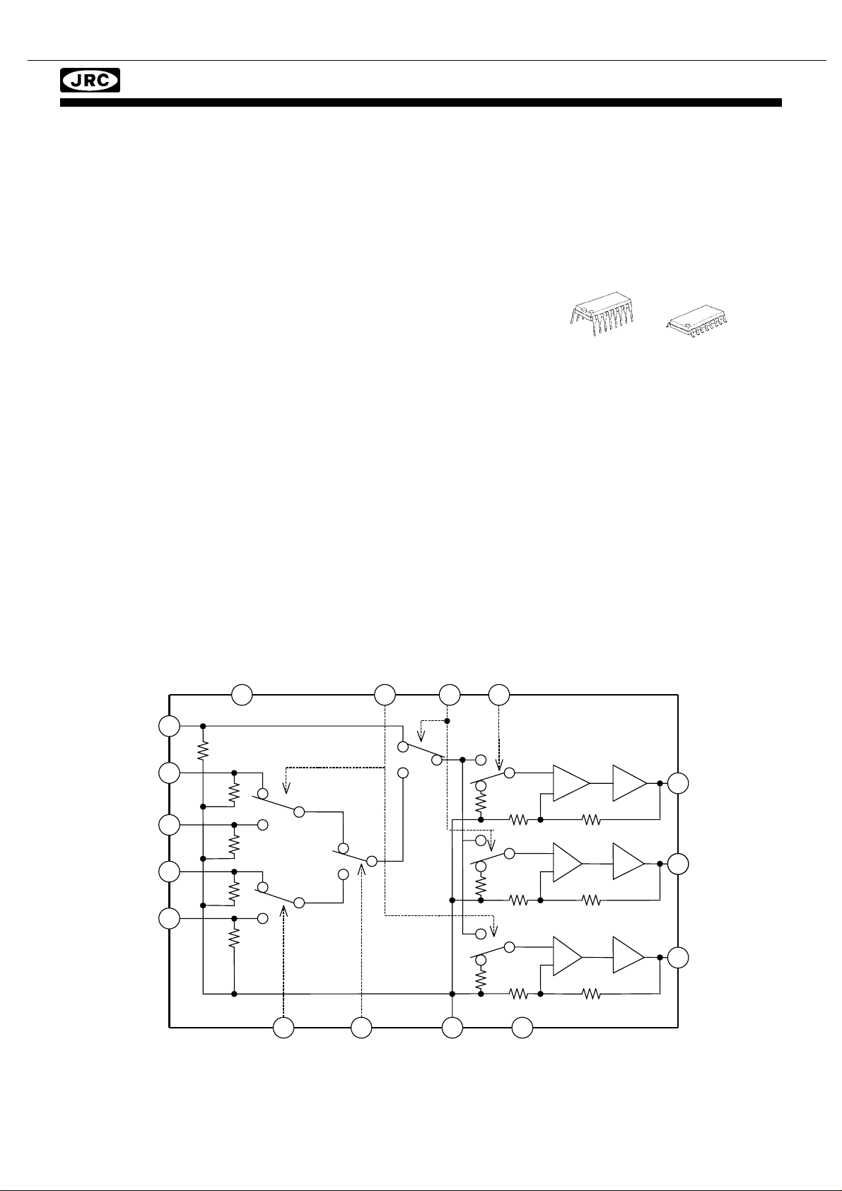
73
AVR145
NJM2595
■ GENERAL DESCRIPTION ■ PACKAGE OUTLINE
The NJM2595 is a 5-input 3-output video switch. Its switches
select one from five signals received from VTR,TV,DVD,
TV-GAME and others.
The NJM2595 is designed for audio items, such as AV amplifier
and others.
5-INPUT 3-OUTPUT VIDEO SWITCH
NJM2595D NJM2595M
■ FEATURES
● 5-input 3-output
● Operating Voltage ±4.0 to ±6.5V
● Operating current ±15mAtyp. at Vcc=±5V
● Crosstalk -65dBtyp.
● Internal 6dB Amplifier
● Internal 75Ω Driver
● Bipolar Technology
● Package Outline DIP16,DMP16
■ PIN CONFIGURATION and BLOCK DIAGRA M
16
+
SW2V
10 14 2
SW1
SW5
harman/kardon
Vin1
Vin2
Vin3
Vin4
Vin5
13
20k
20k
20k
S5
S6
S7
6dB
Amp
6dB
Amp
6dB
Amp
8 12 6 4
-
75Ω
Driver
75Ω
Driver
75Ω
Driver
1
15
11
Vout1
Vout2
Vout3
9
20k
7
20k
5
20k
3
20k
S2
S3
SW3
S4
SW4
S1
GND V
Page 74

74
AVR145
NJM2595
■ EQUIVALENT CIRCUIT
PIN No. PIN NAME INSIDE EQUIVALENT CIRCUIT VOLTAGE
16 V+ 5V
8 V- -5V
12 GND 13
9
7
5
3
Vin1
Vin2
Vin3
Vin4
Vin5
Vcc
harman/kardon
1
15
11
Vout1
Vout2
Vout3
Vin
Vcc
260
2.1k
20k
Gnd
Vee
Vout
0V
0V
4
6
2
Vee
SW3
SW4
SW5
SW
20k
16k
Vcc
-
8k
4k
Gnd
Vee
Page 75

75
AVR145
NJM2595
■ EQUIVALENT CIRCUIT
PIN No. PIN NAME INSIDE EQUIVALENT CIRCUIT VOLTAGE
14
10
SW1
SW2
Vcc
20k
harman/kardon
■ TEST CIRCUIT
V
0.1µF
+
100µF
16 15 14 13 12 11
+
Vout2.2 Vout2.1
75
Ω
75
Ω
+
V
Vout2
SW
32k
-
16k
4k
Gnd
Vee
Vout3.2
V
CL
V
SW1
SW1
CH
75
Ω
Vin1
10µF
+
Vin1
75
Ω
75
Ω
GND
Vout3.1
V
Vout3
V
CH
SW2
10
SW2
CL
75
Ω
Vin2
10µF
+
9
Vin2
-
Vout1
1
75
Ω
75
Ω
Vout1.2 Vout1.1
SW5
SW5
V
V
CL
CH
Vin5
+
10µF
Vin5
75
Ω
SW3
SW3
V
V
CL
CH
Vin4
+
10µF
Vin4
75
Ω
SW4
SW4
V
V
CL
CH
Vin3
+
10µF
Vin3
75
Ω
V
8765432
V
0.1µF
-
+
100µF
Page 76

76
AVR145
harman/kardon
Page 77

77
AVR145
harman/kardon
Page 78

78
AVR145
harman/kardon
Page 79

79
AVR145
harman/kardon
Page 80
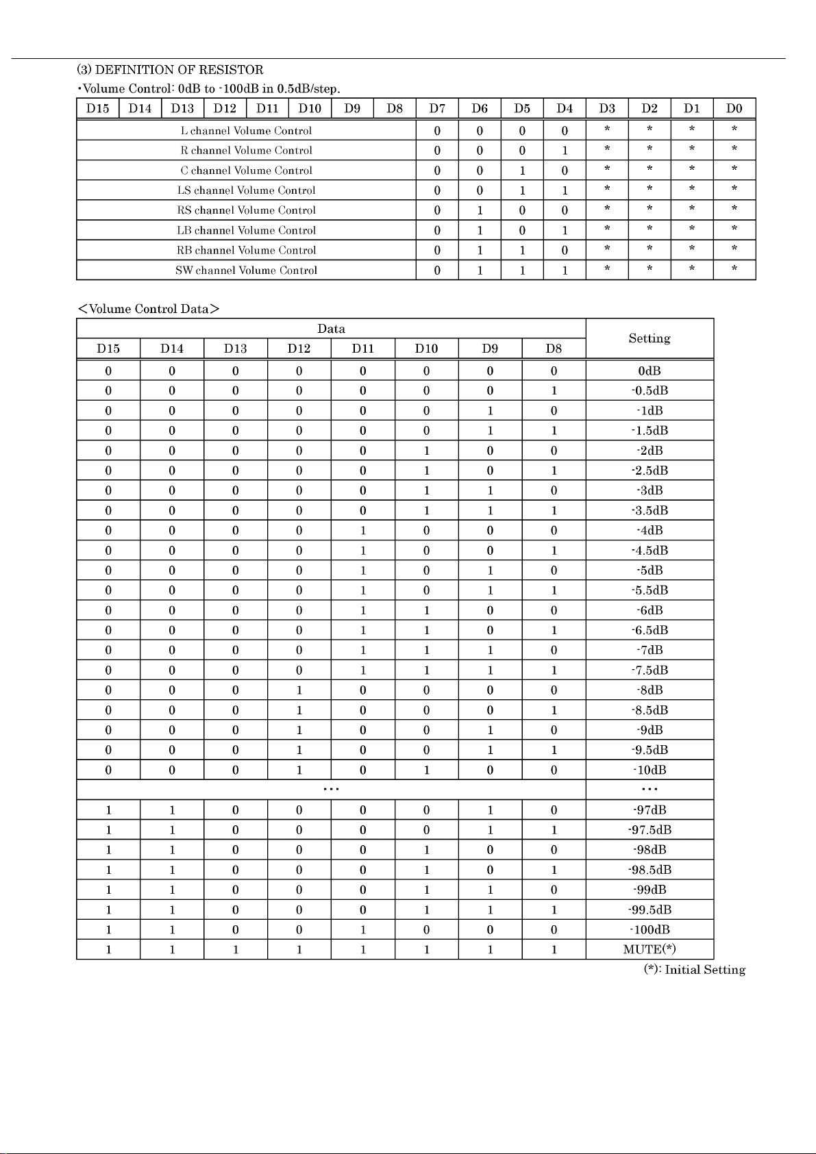
80
AVR145
harman/kardon
Page 81

81
AVR145
harman/kardon
Page 82
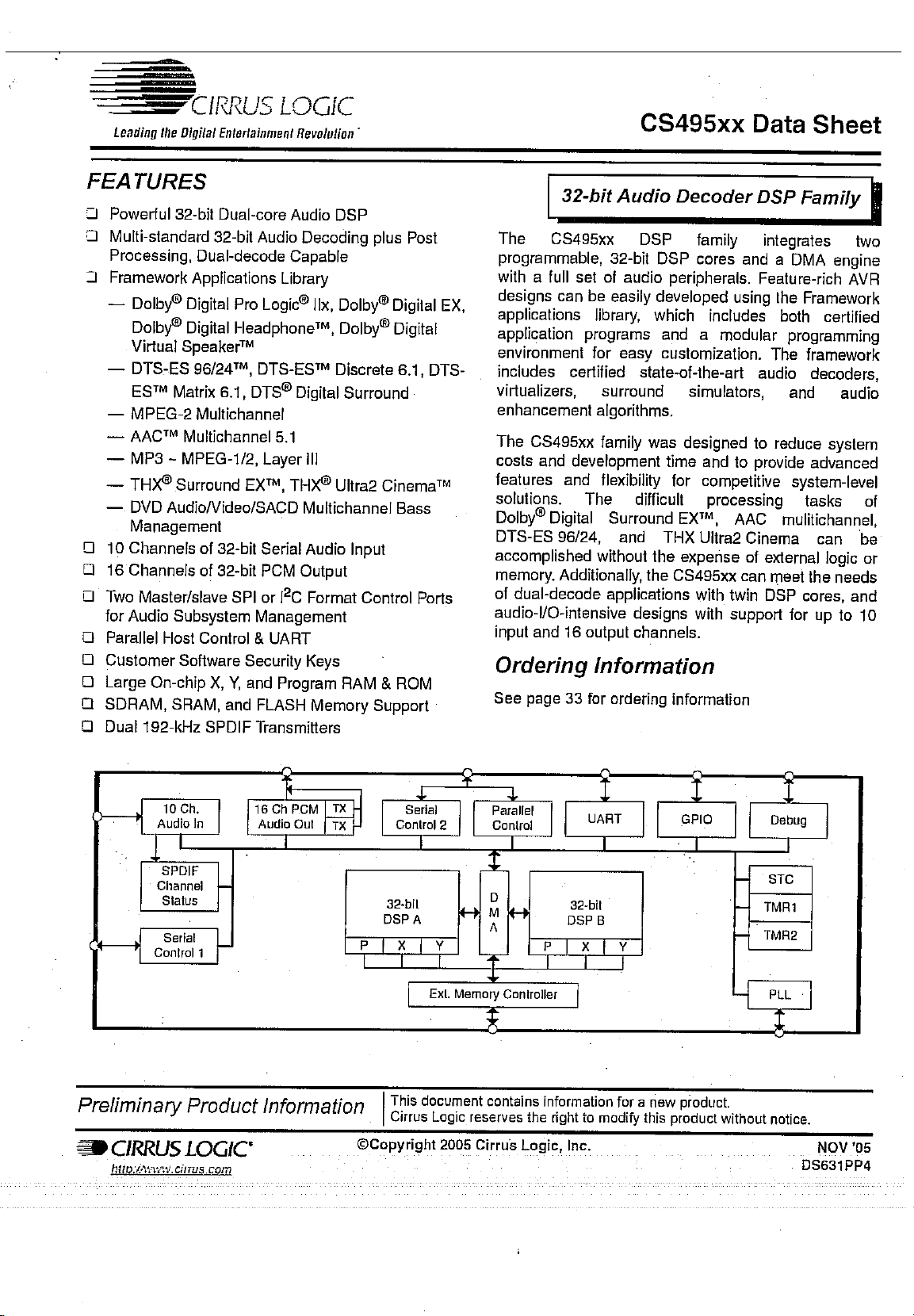
82
AVR145
harman/kardon
Page 83
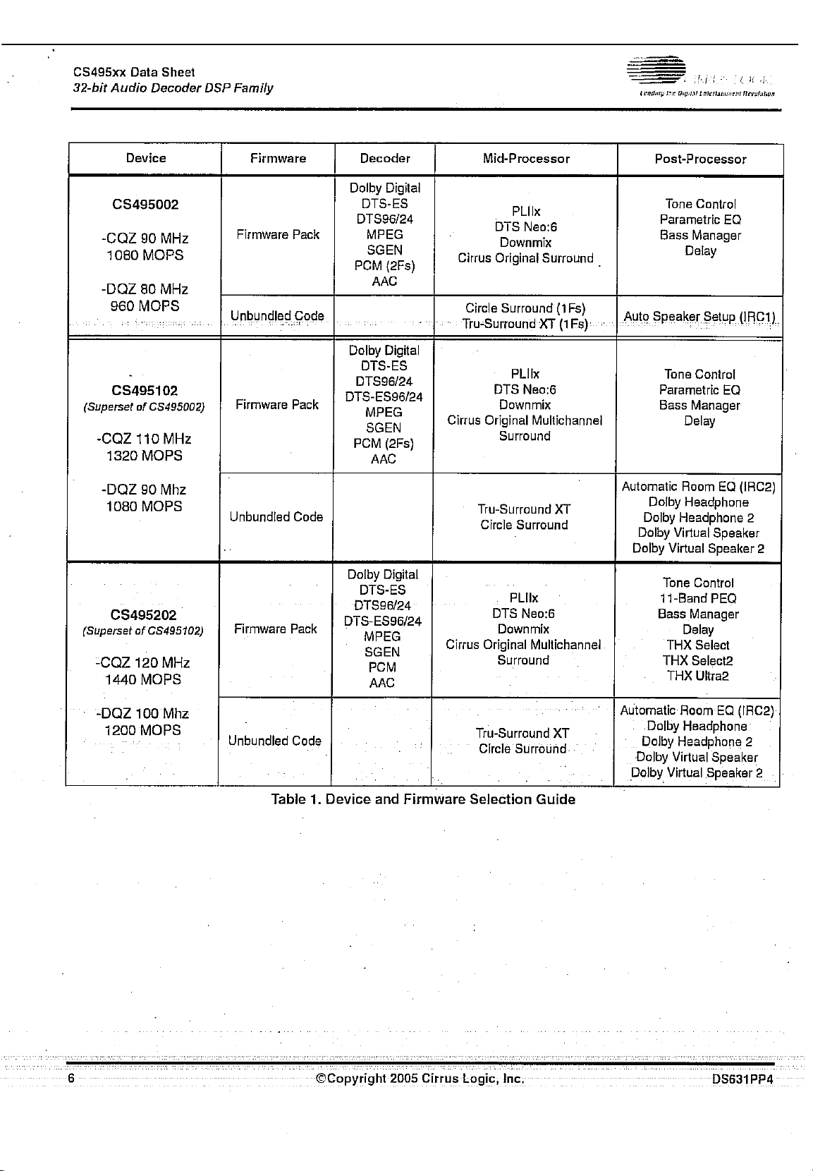
83
AVR145
harman/kardon
Page 84

84
AVR145
harman/kardon
Page 85
85
AVR145
harman/kardon
Page 86
86
AVR145
harman/kardon
Page 87
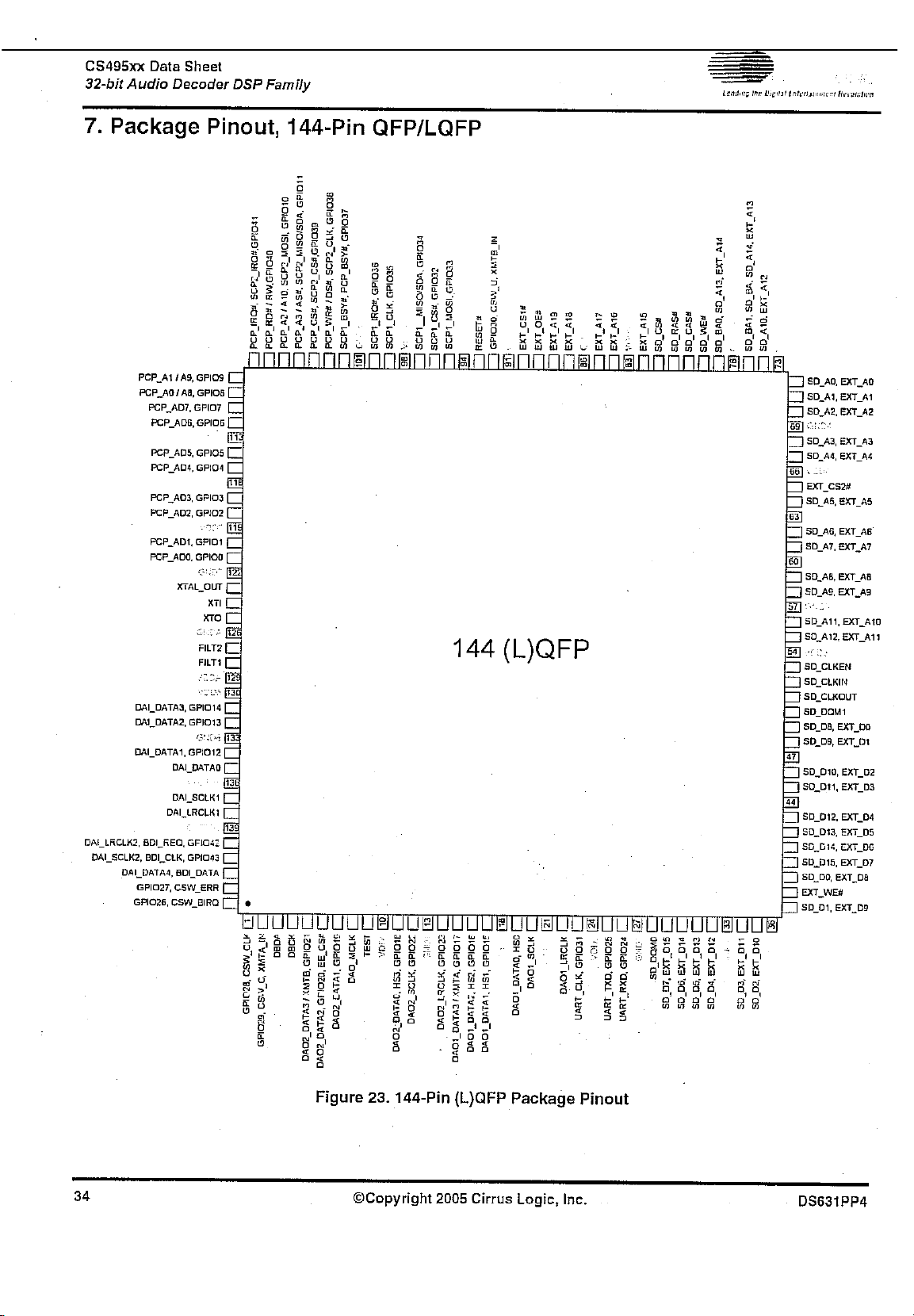
87
AVR145
harman/kardon
Page 88
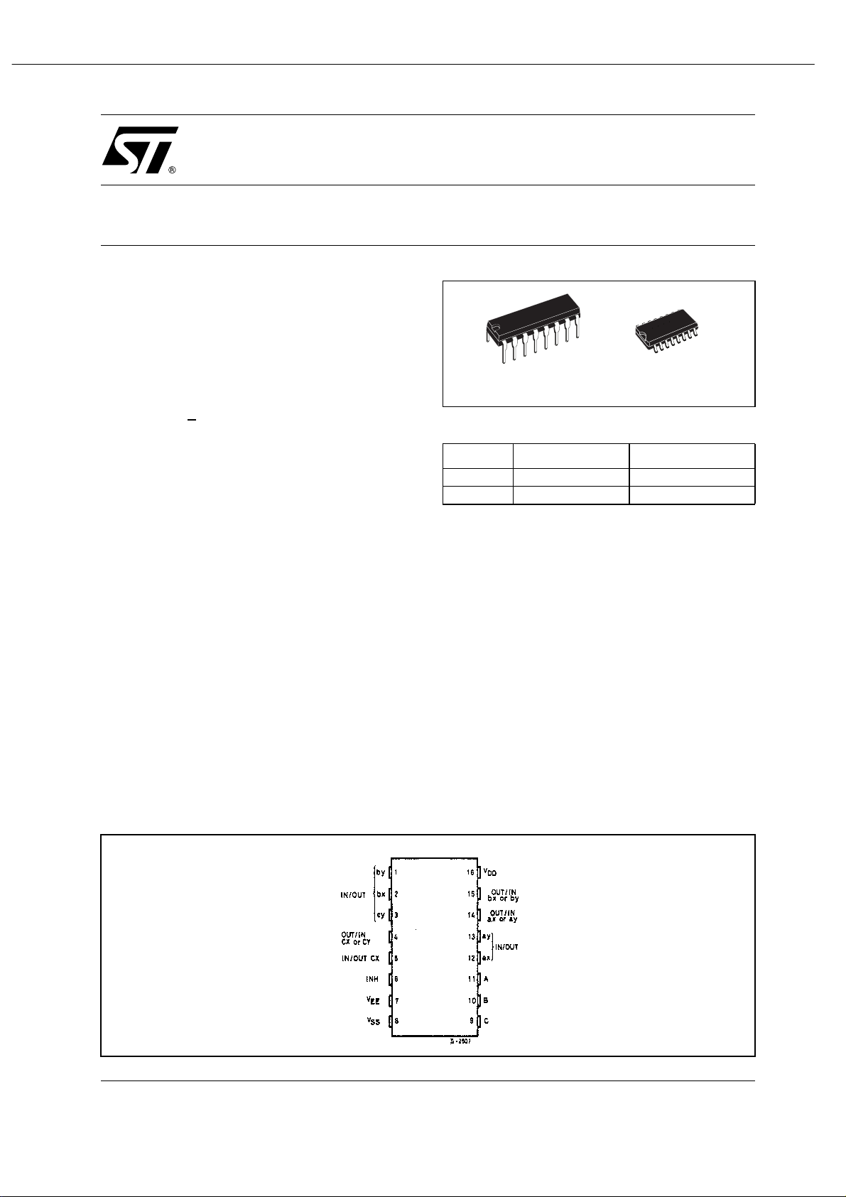
88
AVR145
HCF4053B
ANALOG MULTIPLEXER/DEMULTIPLEXER
TRIPLE 2-CHANNEL
■ LOW "ON" RESISTANCE : 125Ω (Typ.)
OVER 15V p.p SIGNAL-INPUT RANGE FOR
V
DD-VEE
■ HIGH "OFF" RESISTANCE : CHANNEL
LEAKAGE ± 100pA (Typ.) at V
■ BINARYA DDRE SS DECODING ON CHIP
■ HIGH DEGREE OF LINEARITY : < 0.5%
DISTORTIONTYP. at f
V
DD-VSS
■ VERY LOW QUIESCENT POWER
= 15V
=1KHz,VIS=5Vpp,
IS
> 10V,RL = 10KΩ
DD-VEE
=18V
DISSIPATION UNDER ALL DIGITAL
CONTROL INPUT AND SUPPLY
CONDITIONS : 0.2
at V
■ MATCHED SWITCH CHARACTERISTICS :
■ WIDE RANGE OF DIGITAL AND ANALOG
DD-VSS=VDD-VEE
R
=5Ω (Typ.) FOR VDD-VEE= 15V
ON
µW(Typ.)
=10V
SIGNAL LEVELS : DIGITAL3 to 20,
ANALOG TO 20V p.p.
■ QUIESCENT CURRENT SPECIF. UP TO 20V
■ 5V, 10V AN D 15V PARAMETRIC RATINGS
■ INPUT LEAKAGE CURRENT
I
= 100nA (MAX) AT VDD=18VTA= 25°C
I
■ 100% TESTED FOR QUIESCENT CURRENT
■ MEETS ALL REQUIREMENTS OF JEDEC
JESD13B " STANDARD SPECIFICATIONS
FOR DESCRIPTION OF B SERIES CMOS
DEVICES"
DESCRIPTION
The HCF4053B i s a monolithic integrated circuit
fabricated in Metal Oxide Semiconductor
DIP SOP
ORDER CODES
PACKAGE TUBE T & R
DIP HCF4053BEY
SOP HCF4053BM1 HCF4053M013TR
technology available in DIP and SOP packages.
The HCF4053B analog multiplexer/demultiplexer
is a digitally controlled analog switch having low
ON impedance and very low OFF lea ka ge current.
This multiplexer circuit dissipate extremely low
quiescent power over the full V
V
supply voltage rang e, independent of the
EE
DD-VSS
logic state of the cont rol signals.
When a logic "1" is present at the inhibit input
terminal all channel are off. This device is a triple
2-channel multiplexer having three separate
digital control inputs, A, B, and C, and an inhibit
input. Each control input selects one of a pair of
channels which are connected in a single pole
double-throw configuration.
harman/kardon
and VDD-
PIN CO NNE CTION
1/10October 2002
Page 89

89
AVR145
HCF4053B
INPUT E QUIVALENT CIRCUIT PIN DESCRIPTION
PIN No SYMBOL NAME AND FUNCTION
11, 10, 9 A, B, C Binary Control Inputs
6 INH Inhibit Inputs
12, 13, 2, 1,
5, 3
14 OUT/IN ax or ay
15 OUT/IN bx or by
4 OUT/IN cx or cy
7
8
16
IN/OUT
V
V
V
TRUTH TABLE
EE
SS
DD
ax,ay,bx,by,cx,cy Input/
Output
Supply Voltage
Negative Supply Voltage
Positive Supply Voltage
harman/kardon
FUNCTIONAL DIAGRAM
INHIBIT C or B or A
0 0 ax or bx or cx
0 1 ay or by or cy
1 X NONE
X : Don’t Care
2/10
Page 90

90
AVR145
harman/kardon
Page 91

91
AVR145
harman/kardon
Page 92

92
AVR145
harman/kardon
Page 93

93
AVR145
harman/kardon
Page 94

94
AVR145
harman/kardon
Page 95

95
AVR145
harman/kardon
Page 96
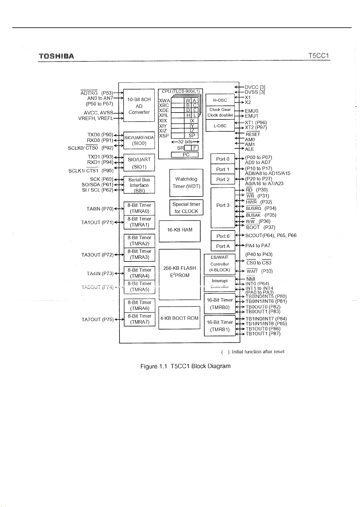
96
AVR145
harman/kardon
Page 97
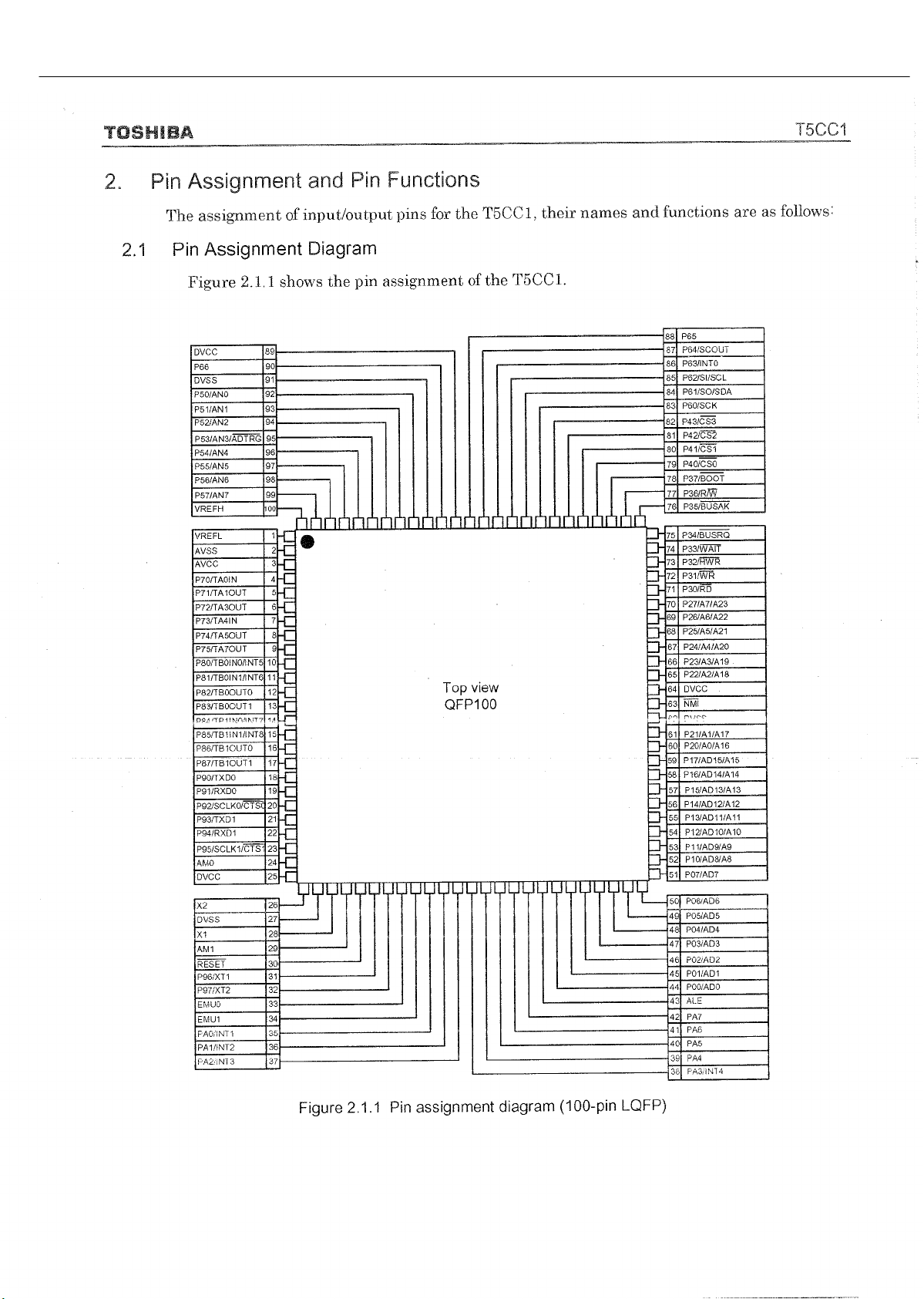
97
AVR145
harman/kardon
Page 98
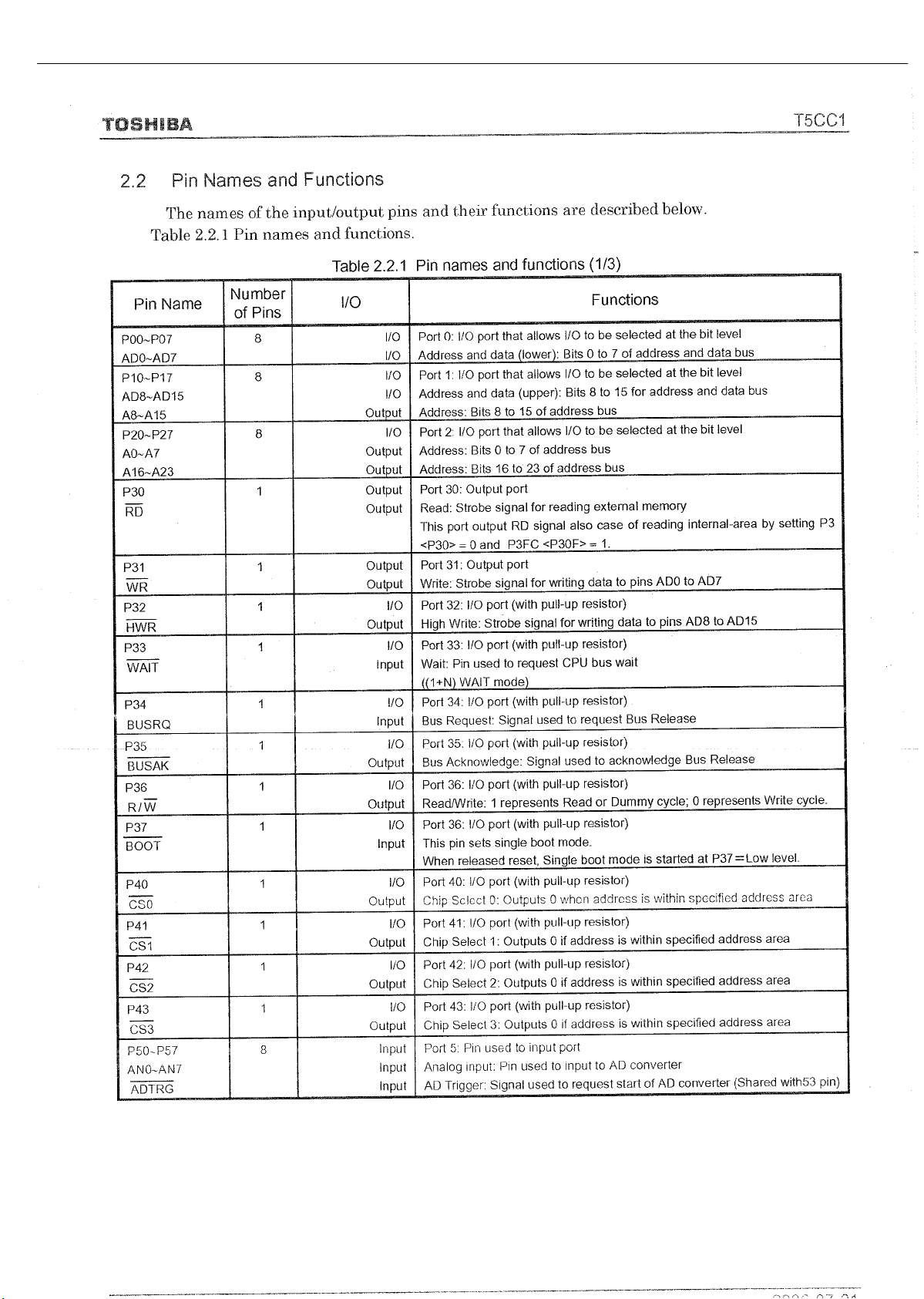
98
AVR145
harman/kardon
Page 99
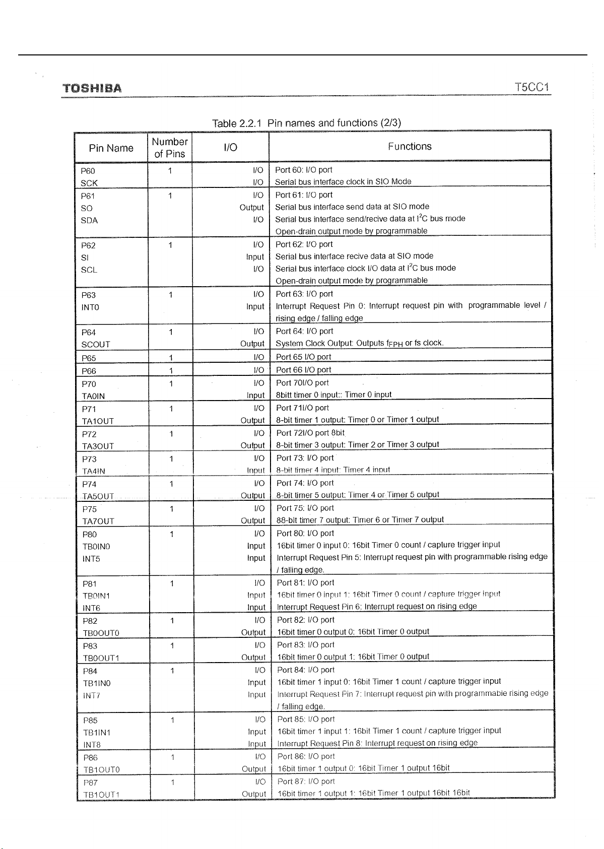
99
AVR145
harman/kardon
Page 100

100
AVR145
harman/kardon
 Loading...