

Page 1
Instruction Manual
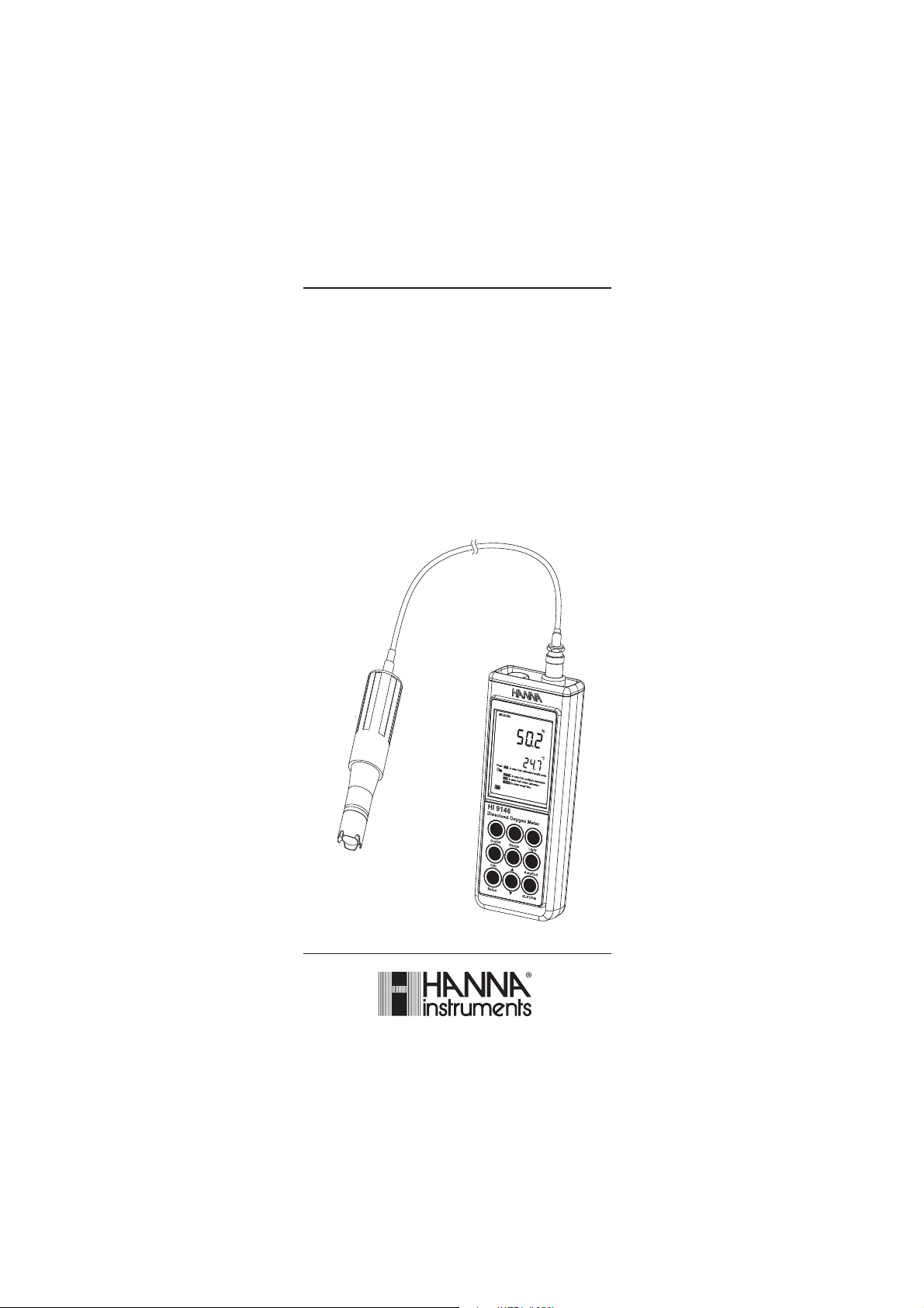
HI 9146
Dissolved Oxygen
and
Temperature Meter
www.hannainst.com
1
Page 2

Dear Customer,
Thank you for choosing a Hanna Instruments product.
Please read this instruction manual carefully before using this instrument.
This manual will provide you with the necessary information for correct
use of this instrument, as well as a precise idea of their versatility.
If you need additional technical information, do not hesitate to e-mail us
at tech@hannainst.com.
WARRANTYWARRANTY
WARRANTY
WARRANTYWARRANTY
HI 9146 is guaranteed for two years against defects in workmanship and
materials when used for its intended purpose and maintained according
to instructions. Electrodes and probes are guaranteed for six months. This
warranty is limited to repair or replacement free of charge.
Damage due to accidents, misuse, tampering or lack of prescribed
maintenance is not covered.
If service is required, contact the dealer from whom you purchased the
instrument. If under warranty, report the model number, date of
purchase, serial number and the nature of the problem. If the repair is
not covered by the warranty, you will be notified of the charges incurred.
If the instrument is to be returned to Hanna Instruments, first obtain a
Returned Goods Authorization number from the Technical Service
department and then send it with shipping costs prepaid. When
shipping any instrument, make sure it is properly packed for complete
protection.
TABLE OF CONTENTSTABLE OF CONTENTS
TABLE OF CONTENTS
TABLE OF CONTENTSTABLE OF CONTENTS
WARRANTY ........................................................................................................... 2
PRELIMINARY EXAMINATION ................................................................................. 3
GENERAL DESCRIPTION ......................................................................................... 3
PROBE FUNCTIONAL DESCRIPTION ......................................................................... 4
METER FUNCTIONAL DESCRIPTION ......................................................................... 5
SPECIFICATIONS ................................................................................................... 7
OPERATIONAL GUIDE ............................................................................................. 8
AutoEnd ............................................................................................................. 12
DO CALIBRATION ................................................................................................. 12
GOOD LABORATORY PRACTICE (GLP) ..................................................................... 15
SETUP ................................................................................................................ 17
DO CONCENTRATION VERSUS SALINITY CHART ..................................................... 18
DO CONCENTRATION VERSUS ALTITUDE CHART ..................................................... 19
TEMPERATURE CALIBRATION (for technical personnel only) .................................. 20
BATTERIES REPLACEMENT .................................................................................... 21
LCD MESSAGE GUIDE ........................................................................................... 22
PROBE & MEMBRANE MAINTENANCE .................................................................. 23
TROUBLESHOOTING GUIDE .................................................................................. 25
ACCESSORIES ..................................................................................................... 26
2
Page 3

PRELIMINARY EXAMINATIONPRELIMINARY EXAMINATION
PRELIMINARY EXAMINATION
PRELIMINARY EXAMINATIONPRELIMINARY EXAMINATION
Remove the instrument from the packing material and examine it carefully
to make sure that no damage has occurred during shipping. If there is any
damage, notify your Dealer or the nearest Hanna Customer Service Center.
Each instrument is supplied with:
• HI 76407/2 DO probe with 2 m (6.7’) cable
• HI 76407A membarne cap (2 pcs.)
• HI 7041S electrolyte solution (30 mL)
• 3 x 1.5V AAA, Batteries
• Instruction Manual
• Rugged Carrying Case
Note: Save all packing material until you are sure that the instrument
functions correctly. All defective items must be returned in the
original packing with the supplied accessories.
GENERAL DESCRIPTIONGENERAL DESCRIPTION
GENERAL DESCRIPTION
GENERAL DESCRIPTIONGENERAL DESCRIPTION
HI 9146 is state-of-the-art, heavy-duty DO meter, designed to provide
laboratory results and accuracy under harsh industrial conditions.
This instrument is provided with a series of new diagnostic features and
messages on the LCD which add an entirely new dimension to the
measurement of DO, by allowing the user to dramatically improve the
reliability of the measurement.
The Auto Endpoint feature automatically freezes the display when a
stable reading is reached.
Dissolved Oxygen is indicated in ppm (parts per million) or in %. All
measurements are automatically compensated for temperature. Salinity
compensation in water allows direct determination of Dissolved Oxygen in
saline waters and altitude compensation readjusts for the altitude variance.
The Dissolved Oxygen probe has a membrane covering the polarographic
sensors and a built-in thermistor for temperature measurements and
compensation. This permeable PTFE membrane isolates the sensor
elements from the testing solution, but allows Oxygen to pass through.
When a voltage is applied across the sensor, oxygen that has passed
through the membrane reacts causing a current flow, and hence
determining a reading.
The Battery Error Preventing System (BEPS) detects when the batteries
become too weak to ensure reliable measurements.
The backlight feature is automatically disabled when batteries are
getting low and a clear indication is displayed to warn the user of this
condition. However, the meter continues to measure correctly even when
the low battery indication is displayed. The meter automatically switches
itself off when the batteries are too weak to support proper function.
In addition, the meter allow the user to enter an ID code to uniquely
identify the instrument.
3
Page 4
7
8
10
9
3
4
1
2
4
5
6
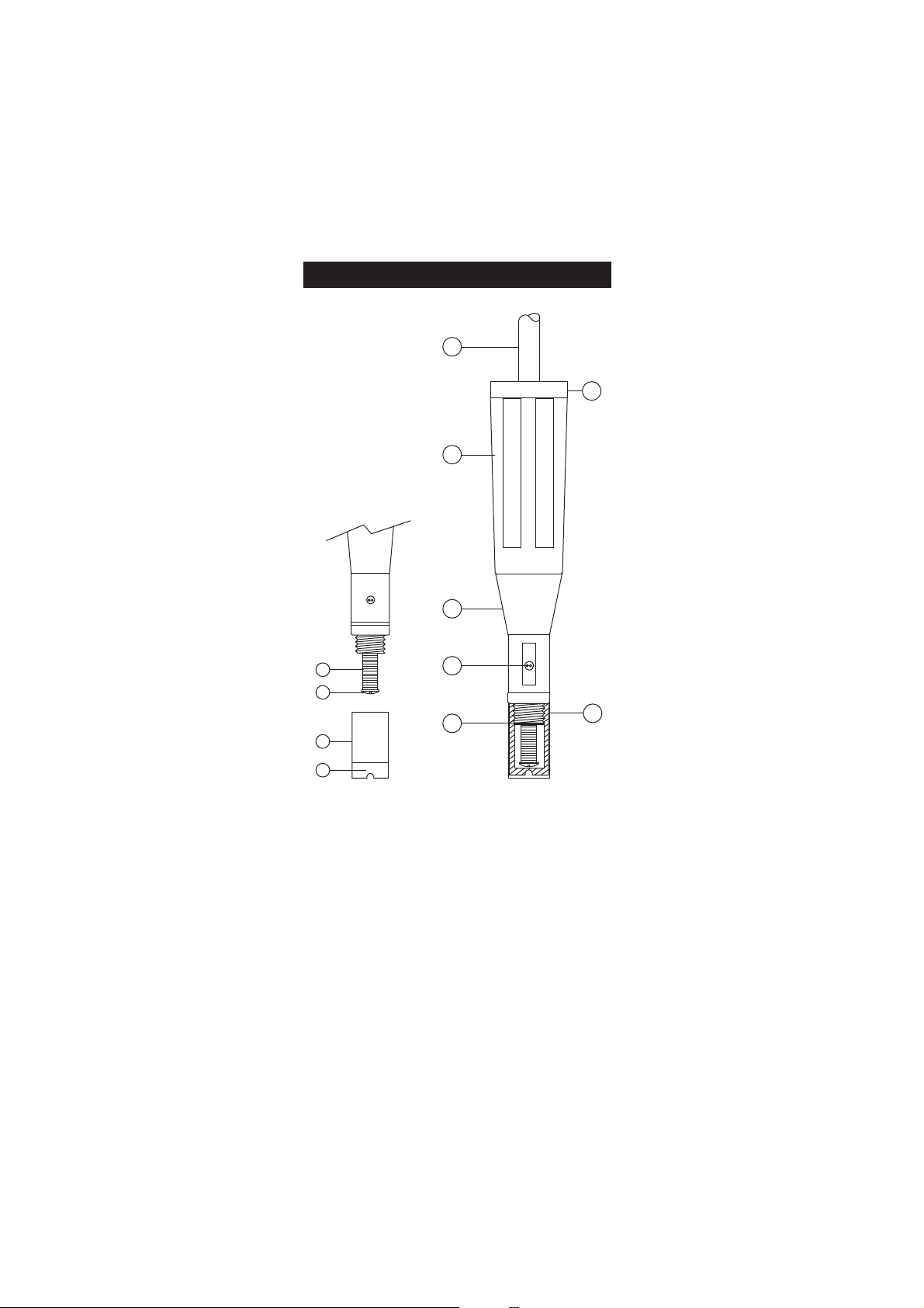
PROBE FUNCTIONAL DESCRIPTIONPROBE FUNCTIONAL DESCRIPTION
PROBE FUNCTIONAL DESCRIPTION
PROBE FUNCTIONAL DESCRIPTIONPROBE FUNCTIONAL DESCRIPTION
1. D.O. Probe
2. Protective Cap
3. Watertight Shielded Cable
4. Polypropylene Probe Body
5. Temperature Sensor
6. O-Ring Seal
7. Silver Chloride Anode
8. Platinum Cathode (sensor)
9. Oxygen Permeable PTFE Membrane
10. Membrane Cap
4
Page 5
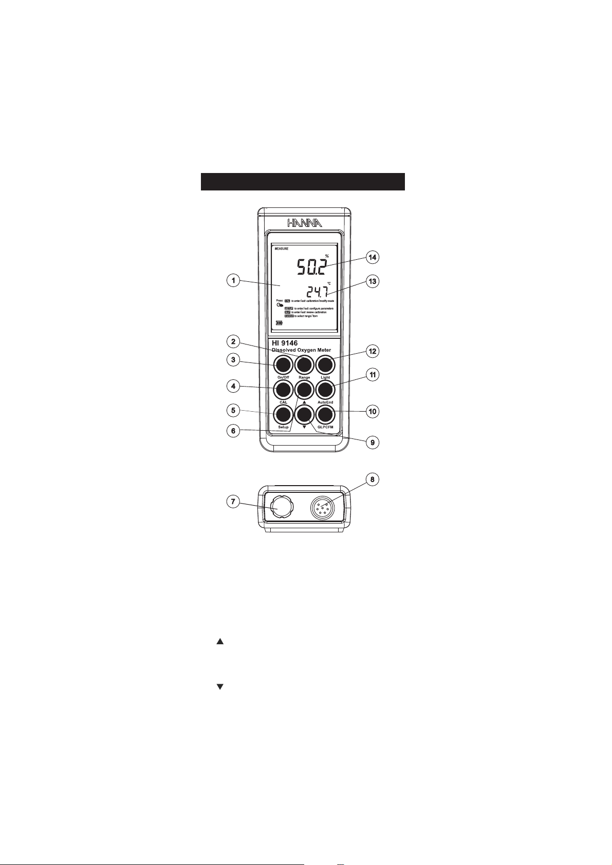
METER FUNCTIONAL DESCRIPTIONMETER FUNCTIONAL DESCRIPTION
METER FUNCTIONAL DESCRIPTION
METER FUNCTIONAL DESCRIPTIONMETER FUNCTIONAL DESCRIPTION
1) Liquid Crystal Display (LCD).
2) Range key, to select ppm or % range.
3) On/Off key, to turn the instrument ON and OFF.
4) CAL key, to enter/exit calibration mode.
5) Setup key, to enter/exit SETUP mode.
6) key, to manually increase temperature or other parameters.
7) Battery compartment cap.
8) DIN connector for DO probe.
9) key, to manually decrease temperature or other parameters.
5
Page 6

10) GLP key, to display Good Laboratory Practice information.
CFM key, to confirm different values.
11) AutoEnd key, to freeze first stable reading on the LCD.
12) Light key, to toggle display backlighting.
13) Secondary LCD.
14) Primary LCD.
6
Page 7
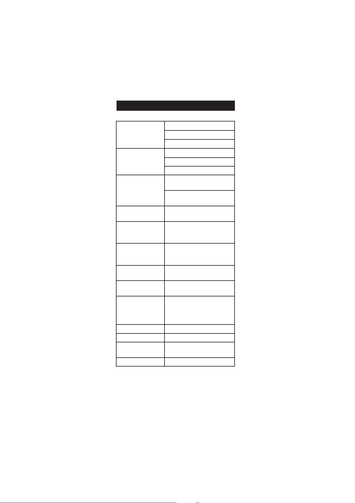
EGNAR
mpp00.54ot00.0
%0.003ot0.0
Cº0.05ot0.0
NOITULOSER
mpp10.0
%1.0
C°1.0
YCARUCCA
F°86/C°02@
roelacslluffo%5.1±
retaergrevehcihwtigid1±
rorreeborpgnidulcxeCº2.0±
noitarbilaC.O.D
%0tatniopelbuodroelgniS
( 0407IH )riani(%001dna)
edutitlA
noitasnepmoC
noituloseR
)'021,31(m000,4ot0
)'823(m001
ytinilaS
noitasnepmoC
noituloseR
l/g08ot0
l/g1
noitasnepmoCerutarepmeT
Cº0.05ot0.0
)Fº221ot23(
eborP
F4/70467IH elbacm4htiw
F01/70467IH elbacm01htiw
efiL&epyTyrettaB
seirettabAAAV5.1x3
esusuounitnocfosruoh002.xorppa
htiwsruoh05(thgilkcabtuohtiw
)thgilkcab
snoisnemiD )"4.1x8.2x3.7(mm63x27x581
thgieW )zo6.01(g003
tnemnorivnE
)Fº221-23(Cº05–0
gnisnednocnon%59HRxam
ytnarraW sraey2
SPECIFICATIONSSPECIFICATIONS
SPECIFICATIONS
SPECIFICATIONSSPECIFICATIONS
7
Page 8
Shipping
cap
black
red
FILLFIRST
THENTAP
THENSCREW
BACKON
OPERATIONAL GUIDEOPERATIONAL GUIDE
OPERATIONAL GUIDE
OPERATIONAL GUIDEOPERATIONAL GUIDE
INITIAL PREPARATION
The instrument is supplied complete with batteries. In order to place the
batteries inside the instrument follow the instructions from page 21.
To take measurements, connect the DO probe to the meter securely by
aligning the pins with the socket located on the back of the meter,
pushing the plug in and tightening the threaded ring.
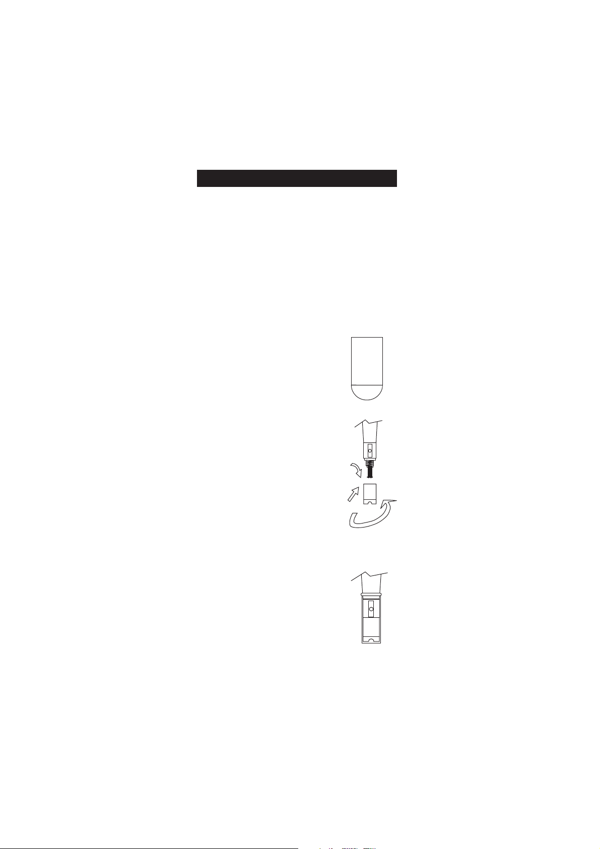
Probes shipped from Hanna Instruments are dry. To hydrate the probe
and prepare it for use, connect it to the meter and proceed as follows:
1. Remove the red and black plastic cap.
This cap is for shipping purposes and
can be thrown away.
2. Wet the sensor by soaking the bottom
2½ cm (1") of the probe in electrolyte
(HI 7041S) for 5 minutes.
3. Rinse the membrane cap (HI 76407A
supplied in the kit with the meter)
with electrolyte solution while shaking
it gently. Refill with clean electrolyte
solution.
4. Tap gently the sides of the membrane
cap with your finger tip to ensure that
no air bubbles are trapped. To avoid
damaging the membrane, do not tap
it directly on the bottom.
5. Make sure that the rubber O-ring sits
properly inside the membrane cap.
6. With the sensor facing down, slowly
screw the cap clockwise. Some electrolyte
will overflow.
When not in use and during polarization
(see page 9), use the protective transparent
cap supplied in the kit with the meter.
8
Page 9
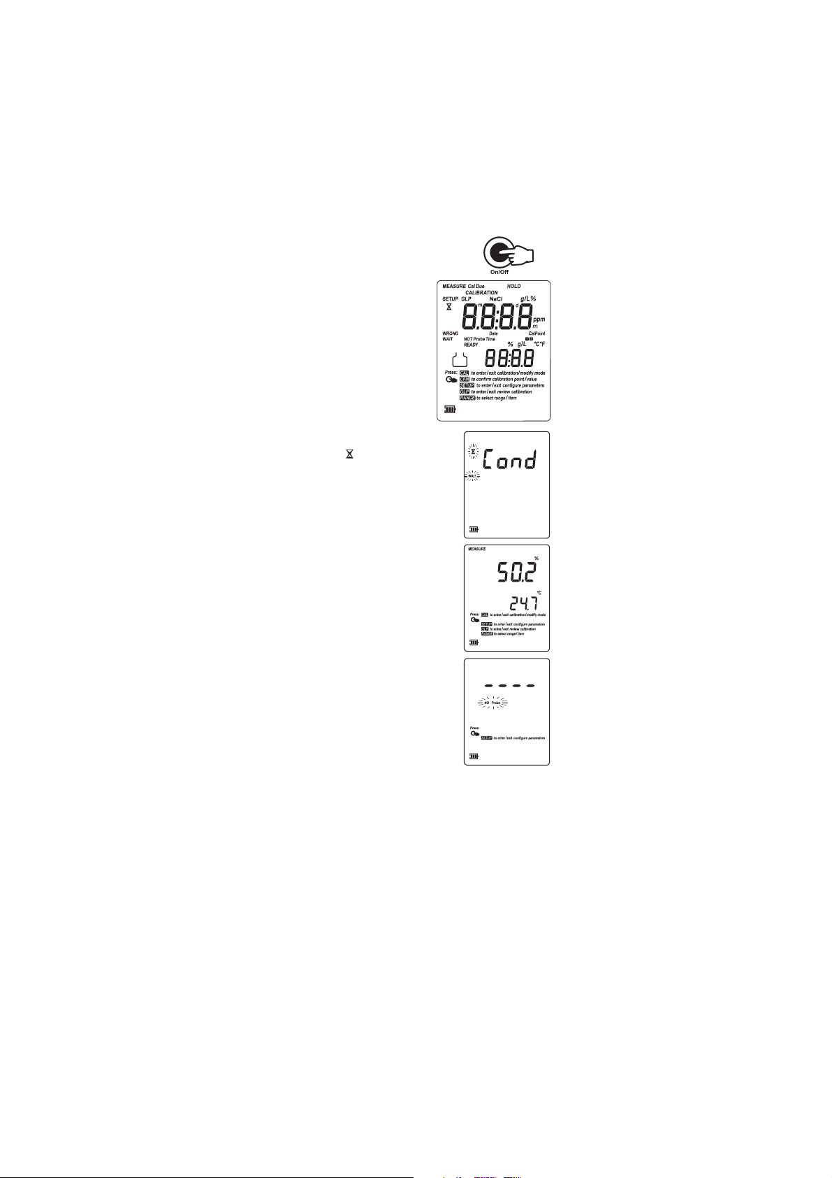
Turn the instrument ON by pressing On/Off.
At start-up the display will show all
the used segments for a few seconds
(or while the button is held), followed
by the percentage indication of the
remaining battery life.
• After a few seconds “Cond” message
appears, the “ ” and “WAIT” tags will
blink on the LCD if probe is connected
to inform the user that the probe is in
auto-conditioning (automatic polarization)
mode.
• When this message disappears, the probe
is polarized and the instrument can be
calibrated.
• The meter is now ready to operate.
• If the probe is disconnected or broken, the
meter will display “----” and “NO Probe”
tag blinking. In this situation only SETUP
menu is available.
The auto-off feature turns the instrument off
after a set period (default 20 min) with no
button pressed to save battery life. To set
another period or to disable this feature, see SETUP menu on page 17.
The auto-off backlight feature turns the backlight off after a set period
(default 1 min) with no buttons pressed. To set another period or to
disable this feature, see SETUP menu on page 17.
PROBE POLARIZATION
The probe is under polarization with a fixed voltage of approximately
800 mV.
Probe polarization is essential for stable measurements with the same
recurring degree of accuracy.
9
Page 10

With the probe properly polarized, oxygen is continually consumed
when it passes through the sensitive diaphragm and dissolves in the
electrolyte solution contained in the probe.
If polarization is interrupted, the electrolyte solution continues to be
enriched with oxygen until it reaches an equilibrium with the surrounding
solution.
Whenever measurements are taken with a non-polarized probe, the
oxygen level revealed is both that of the tested solution, as well as that
present in the electrolyte solution. This reading is incorrect.
Keep the protective cap on during polarization time and remove it for
calibration and measurements.
Note: If the probe is changed while the instrumen is ON, a conditioning
period is started.
SALINITY AND ALTITUDE COMPENSATION
If the sample contains significant concentration of salinity or if you are
performing measurements at an altitude different from sea level, the
read out values must be corrected, taking into account the lower degree
of oxygen solubility in these situations (see pages 18-19).
Remember to set the altitude and/or the salinity before taking any DO
measurements. The meter will automatically compensate for these factors.
DO MEASUREMENTS
Make sure that the instrument has been
calibrated and the protective cap has been
removed.
• Immerse the tip of the probe in the sample
to be tested. Allow approximately one
minute for the reading to stabilize.
• The Dissolved Oxygen value (in ppm) is
displayed on the primary LCD and the
temperature on the secondary LCD.
• Press RANGE to change the reading from
ppm to % and vice-versa.
10
Page 11

For accurate Dissolved Oxygen measurements, a water movement of
0.3 m/s is required. This is to ensure that the oxygen-depleted
membrane surface is constantly replenished. A moving stream will
provide adequate circulation.
The use of a magnetic stirrer to ensure a certain fluid velocity is
recommended.
TEMPERATURE MEASUREMENTS
The probe has a built-in temperature sensor.
The measured temperature is indicated on the secondary LCD as shown
above.
Allow the probe to reach thermal equilibrium before taking any
measurement. This can take several minutes. The greater the difference
between the temperature at which the probe was stored and the
temperature of the sample, the longer the time will take to reach thermal
equilibrium.
Notes: • If “----” appears on the primary LCD and “NO Probe” is
displayed blinking, the DO probe is not properly connected or
the temperature is out of range. This also indicates the
posibility of a broken probe cable.
• If the temperature is out of range “ºC” or “ºF” tag is
displayed blinking.
• If the reading is out of range, the full scale value will be
displayed blinking.
• If the reading is not stable, the stability indicator “ ” on.
• Make sure the meter is calibrated before taking measurements.
• If measurements are taken successively in different samples,
to have accurate readings it is recommended to rinse the
probe thoroughly with deionized water before immersion in
the samples.
• To maximize battery life, the meter is automatically switched
off after a set period of non-use. To reactivate the instrument
press the On/Off key. This feature can be disabled (see
SETUP section for details).
BACKLIGHT FEATURE
The instrument is provided with a Backlight feature to
enhance display readability in low light conditions. It
can be easily toggled on and off through the keypad by
pressing Light.
Note: The backlight automatically shuts off after a set time period to
save battery life (see SETUP for details, page 17).
If battery percentage is less than 20% the backlight can not be ON.
11
Page 12

AA
HI 7040
HI 7040
utoEndutoEnd
A
utoEnd
AA
utoEndutoEnd
To freeze the first stable reading on the LCD
press AutoEnd while the instrument is in
measurement mode.
The ”HOLD” tag will be displayed blinking on
the LCD until the reading will stabilize.
When the reading is stable, the “HOLD” tag
stops blinking and the reading is frozen on
the LCD.
Press AutoEnd again to return to normal
measurement mode.
Note: • Pressing Range the instrument will skip to the displayed
range, without leaving AutoEnd mode.
• Pressing Setup then GLP, the instrument leaves AutoEnd
mode and performs the selected function.
DO CALIBRATIONDO CALIBRATION
DO CALIBRATION
DO CALIBRATIONDO CALIBRATION
Calibrate the instrument frequently, especially if high accuracy is required.
The instrument can be calibrated in maximum 2 points: 0.0% (zero
calibration) and 100.0% (slope calibration).
The calibration of this instrument is very simple.
Before proceeding with the calibration, make sure the probe is ready for
measurements (see page 8), i.e. the membrane cap is filled with electrolyte
and the probe is connected to the meter and properly polarized.
For an accurate calibration, it is recommended to wait at least
15 minutes to ensure precise conditioning of the probe.
The zero calibration of the HI 9146 is very stable,
therefore this procedure needs to be performed only
whenever the probe or the membrane is replaced.
However, because the slope calibration is more critical,
it is recommended to perform this procedure every week.
12
Page 13

INITIAL PREPARATION
• Pour small quantities of HI 7040 Zero Oxygen solution into a
beaker. If possible, use a plastic beaker to minimize any EMC
interferences.
• Make sure the probe is ready for measurements (see probe preparation
on page 8), i.e. the membrane is filled with electrolyte and the
probe is connected to the meter.
• Switch the meter on by pressing the On/Off switch.
• For an accurate calibration, it is recommended to wait for at least
15 minutes to ensure precise conditioning of the probe.
• Remove the protective cap from the DO probe.
• Set the appropriate altitude factor (see
page 19). Make sure the salinity factor is
set to zero (see page 18).
ZERO CALIBRATION
• Submerge the probe into HI 7040
zero oxygen solution and stir gently
for 2-3 minutes.
• Press CAL. The “ ” and “NOT READY”
tags will blink on the LCD until the
reading is stable.
• When the reading is stable,and is within
the limits (±15% f.s.) “CFM” starts
blinking. Press CFM to confirm the
“0.0%” DO calibration.
• Press CAL. The instrument will return to measurement mode and will
memorize the zero calibration data. For a
two-point calibration do not press CAL and
follow the procedure below.
13
Page 14

SLOPE CALIBRATION
It is suggested to perform the slope calibration in air.
• Rinse the probe in clean water to remove any
residual zero oxygen solution.
Note: If you did not perform the zero calibration procedure, press CAL
and then the ARROW keys to select the 100% DO calibration
point.
• Dry the probe tip and allow a few seconds for the LCD reading to
stabilize. The “ ” and “NOT READY” tags will blink until the
reading is stable.
• When the reading is stable, “CFM” tag
starts blinking. Press CFM to confirm the
“100.0%” DO calibration.
• If the reading is within the limits (±15%
f.s.), the meter stores the value (and
adjusts the slope point).
• The instrument stores the slope calibration
data and returns to measurement mode.
Note: • If the reading is not close to the
selected calibration point,
“WRONG“ tag will blink.
• If the temperature is out of range
“WRONG” tag together with the
temperature and “°C” tag will
blink.
• HI 9146 has automatic buffer recognition function. If the
ARROW keys are pressed to select the desired calibration
value, the automatic buffer recognition function is disabled.
14
Page 15
GOOD LABORATORY PRACTICE (GLP)GOOD LABORATORY PRACTICE (GLP)
GOOD LABORATORY PRACTICE (GLP)
GOOD LABORATORY PRACTICE (GLP)GOOD LABORATORY PRACTICE (GLP)
GLP is a set of functions that allows storage and retrieval of data
regarding the maintenance and status of the probe.
All data regarding DO calibration is stored for the user to review when
necessary.
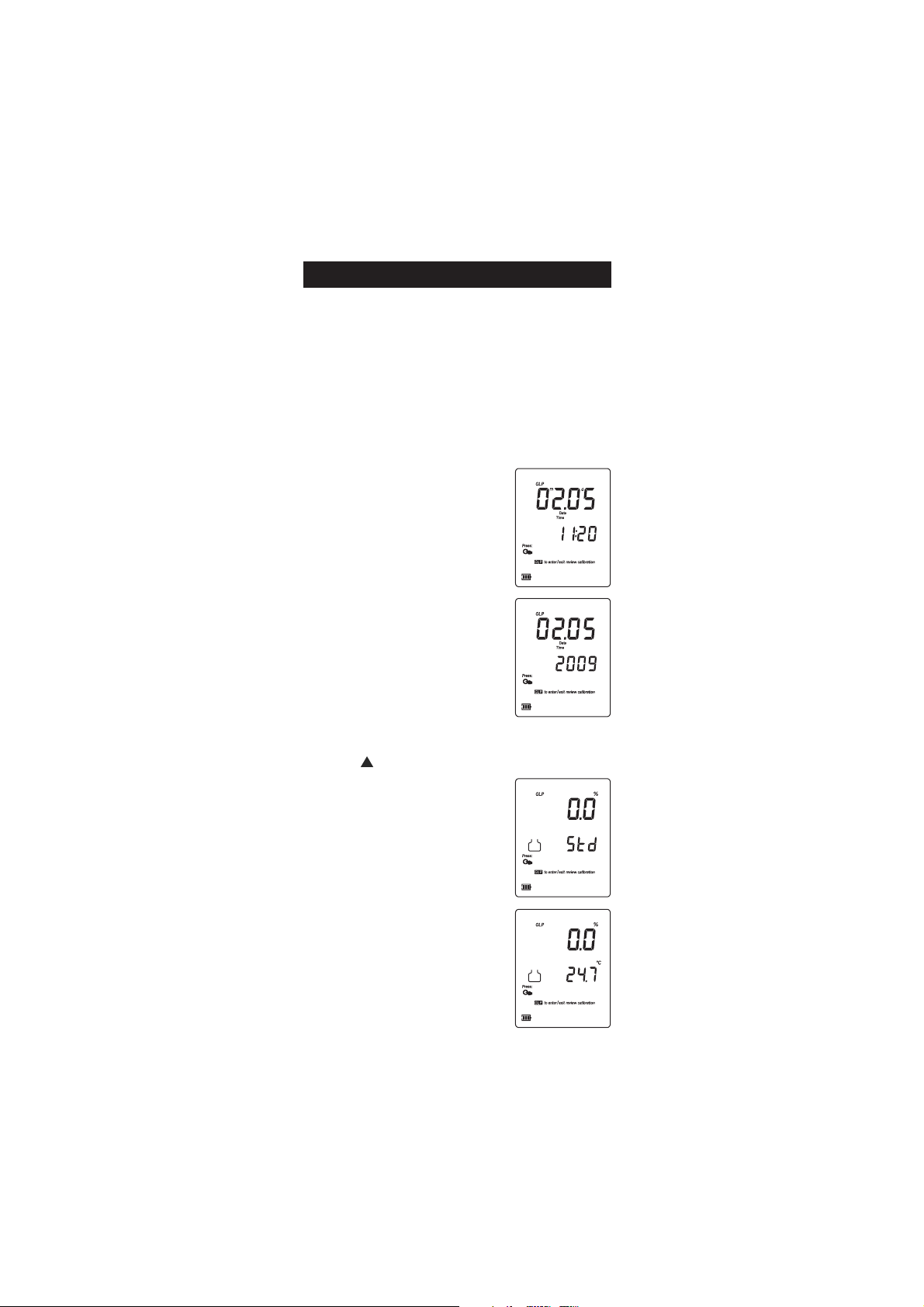
LAST DO CALIBRATION DATA
The last DO calibration data is stored automatically after a successful
calibration. To view the DO calibration data, press GLP when the
instrument is in DO measurement mode.
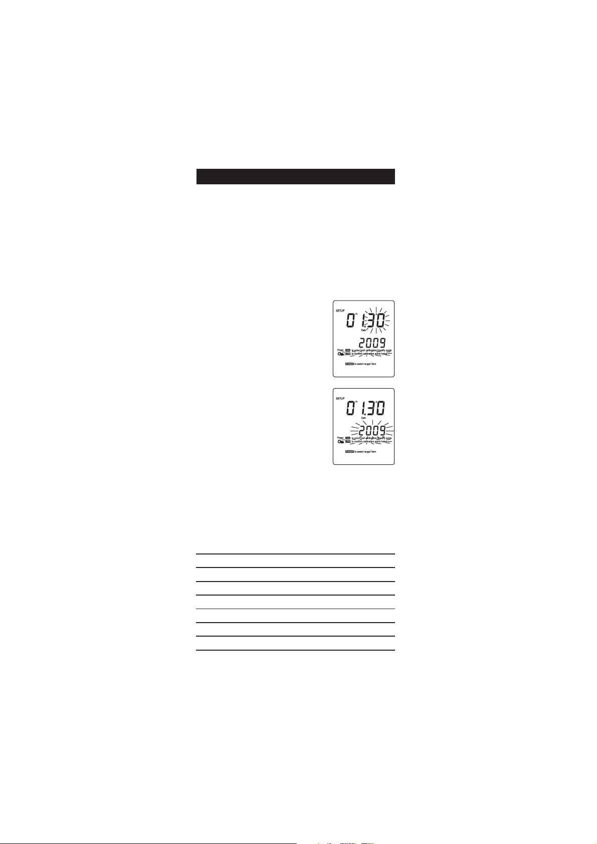
The instrument will display the date (mm.dd)
and the time (hh:mm) of the last calibration.
• Press Setup to view the year for a few
seconds.
Press the ARROW keys to view the next calibration parameter.
Pressing the key:
• The calibration standards.
• Press Setup to view the temperature of
the calibration for a few seconds.
15
Page 16
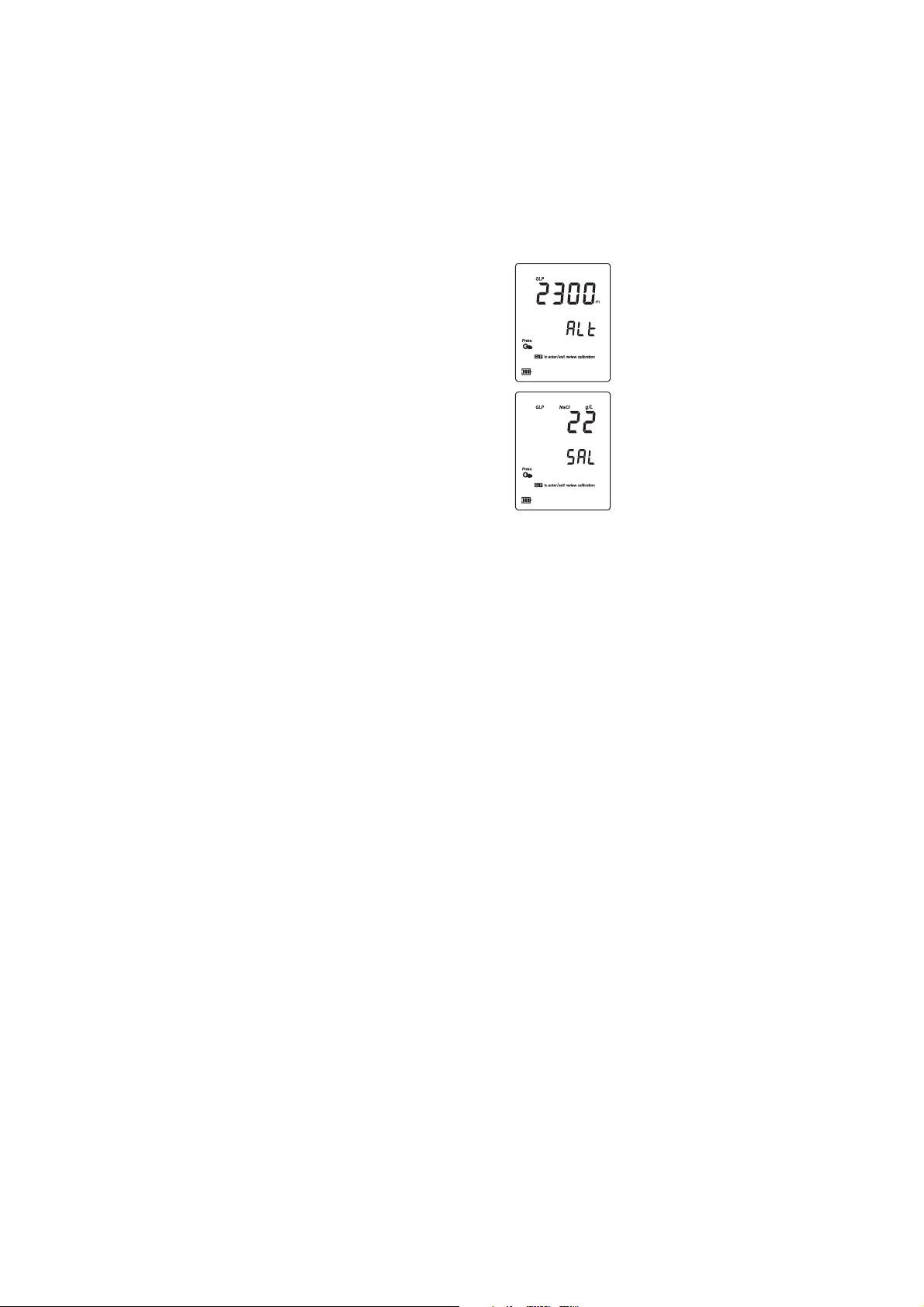
• The altitude value.
• The salinity value.
Press GLP at any moment and the instrument will return to
measurement mode.
16
Page 17
SETUPSETUP
SETUP
SETUPSETUP
Setup mode allows viewing and modifying the following parameters:
• Salinity value (SAL)
• Altitude value (ALt)
• Current Time (hour & minute)
• Current Date (month, day & year)
• Beep Status (bEEP)
• Instrument ID (InSID)
• Auto-off backlight (LIGH)
• Auto power of (AOFF)
• Temperature Unit
To enter SETUP mode, press Setup while the
instrument is in measurement mode.
Select the desired setup parameter using the
ARROW
keys.
Press CAL if you want to change the item
value. “CFM” tag and the selected item (e.g.
hour, in setting up the correct time) will start
blinking.
Press the ARROW
displayed value.
If there is another item to be set (e.g.
minutes), press Range. The other item will
start blinking.
Press the ARROW
Press CFM to confirm or CAL to escape.
Press the ARROW
Press Setup to exit SETUP menu at any time.
The following table lists the SETUP parameters, their valid values range
and the factory settings (default):
Item Description Valid values Default
SAL Salinity value 0 to 80 g/L 0
ALt Altitude value 0 to 4000 m 0
Time Time (hh:mm) 00:00 to 23:59 00:00
Date Date (mm.dd.yyyy) 01.01.2000 to 12.31.2099 01.01.2009
bEEP Beep Status ON/OFF OFF
LIGH Auto-off backlight OFF or 1, 5, 10 min 1
A.OFF Auto power off OFF or 5, 10, 20, 60 min 20
Temperature Unit ºC or ºF ºC
keys to change the
keys to change the displayed value.
keys to select the next/previous parameter.
17
Page 18
Cº
leveLaeSta)l/g(ytinilaS
Fº
l/g0 l/g01 l/g02 l/g03 l/g53
0 06.41 46.31 47.21 09.11 05.11 0.23
2 18.31 19.21 70.21 92.11 19.01 6.53
4 90.31 52.21 74.11 37.01 83.01 2.93
6 44.21 56.11 19.01 22.01 98.9 8.24
8 38.11 90.11 04.01 57.9 44.9 4.64
01 82.11 85.01 39.9 23.9 30.9 0.05
21 77.01 11.01 05.9 29.8 56.8 6.35
41 92.01 86.9 01.9 55.8 03.8 2.75
61 68.9 82.9 37.8 12.8 79.7 8.06
81 54.9 09.8 93.8 09.7 66.7 4.46
02 80.9 65.8 70.8 06.7 83.7 0.86
22 37.8 32.8 77.7 33.7 21.7 6.17
42 04.8 39.7 94.7 70.7 78.6 2.57
52 42.8 97.7 63.7 59.6 57.6 0.77
62 90.8 56.7 32.7 38.6 46.6 8.87
82 18.7 83.7 89.6 16.6 24.6 4.28
03 45.7 41.7 57.6 93.6 22.6 0.68
23 92.7 09.6 45.6 91.6 30.6 6.98
43 50.7 86.6 33.6 10.6 58.5 2.39
63 28.6 74.6 41.6 38.5 86.5 8.69
83 16.6 82.6 69.5 66.5 15.5 4.001
04 14.6 90.6 97.5 05.5 63.5 0.401
24 22.6 39.5 36.5 53.5 22.5 6.701
44 40.6 77.5 84.5 12.5 90.5 2.111
64 78.5 16.5 33.5 70.5 79.4 8.411
84 07.5 74.5 02.5 59.4 58.4 4.811
05 45.5 33.5 70.5 38.4 57.4 0.221
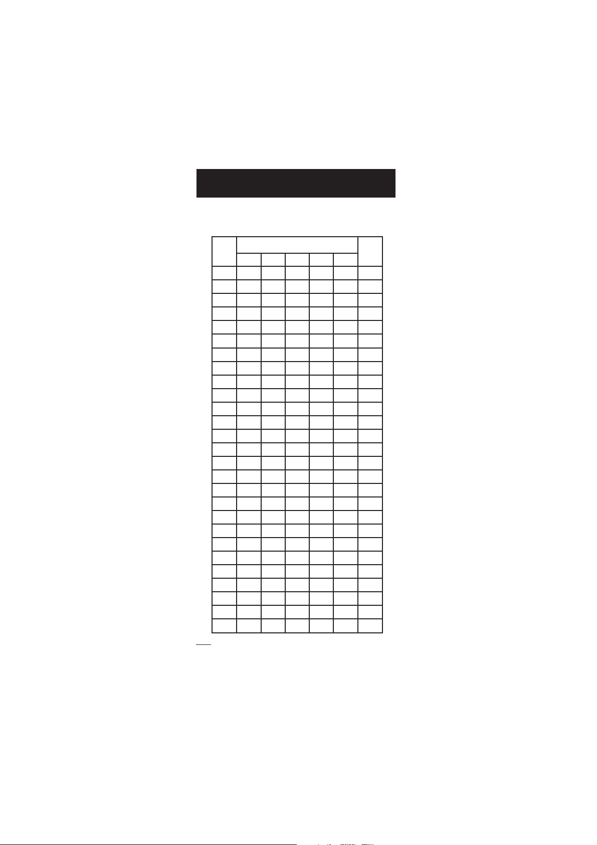
DISSOLVED OXYGEN CONCENTRATIONDISSOLVED OXYGEN CONCENTRATION
DISSOLVED OXYGEN CONCENTRATION
DISSOLVED OXYGEN CONCENTRATIONDISSOLVED OXYGEN CONCENTRATION
VERSUS SALINITY CHARTVERSUS SALINITY CHART
VERSUS SALINITY CHART
VERSUS SALINITY CHARTVERSUS SALINITY CHART
Salinity affects the Dissolved Oxygen concentration expressed in ppm,
decreasing its value. The table below shows the maximum oxygen solubility at various temperatures and salinity levels.
Note: The relationship between salinity and chlorinity for sea water is
given by the equation below:
Salinity (g/l) = 1.80655 Chlorinity (g/l)
18
Page 19

Cº
leveLaeSevobasreteM,edutitlA
Fº
m0
003m006m009m0021m0051m0081m0012m0042m0072m0003m0033m0063m0093m0004
m
0 6.41 1.41 6.31 1.31 6.21 1.21 7.11 2.11 8.01 4.01 0.01 7.9 3.9 0.9 9.8 0.23
2 8.31 3.31 8.21 4.21 9.11 5.11 0.11 6.01 2.01 9.9 5.9 2.9 8.8 5.8 4.8 6.53
4 1.31 6.21 2.21 7.11 3.11 9.01 5.01 1.01 7.9 3.9 0.9 7.8 4.8 0.8 9.7 2.93
6 4.21 0.21 5.11 1.11 7.01 3.01 9.9 6.9 2.9 9.8 6.8 2.8 9.7 6.7 5.7 8.24
8 8.11 4.11 0.11 6.01 2.01 8.9 5.9 1.9 8.8 4.8 1.8 8.7 5.7 3.7 2.7 4.64
01 3.11 9.01 5.01 1.01 7.9 4.9 0.9 7.8 4.8 1.8 8.7 5.7 2.7 9.6 8.6 0.05
21 8.01 4.01 0.01 6.9 3.9 9.8 6.8 3.8 0.8 7.7 4.7 1.7 9.6 6.6 5.6 6.35
41 3.01 9.9 6.9 2.9 9.8 5.8 2.8 9.7 6.7 4.7 1.7 8.6 6.6 3.6 2.6 2.75
61 9.9 5.9 2.9 8.8 5.8 2.8 9.7 6.7 3.7 0.7 8.6 5.6 3.6 1.6 0.6 8.06
81 5.9 1.9 8.8 5.8 1.8 8.7 6.7 3.7 0.7 8.6 5.6 3.6 0.6 8.5 7.5 4.46
02 1.9 8.8 4.8 1.8 8.7 5.7 3.7 0.7 7.6 5.6 2.6 0.6 8.5 6.5 5.5 0.86
22 7.8 4.8 1.8 8.7 5.7 2.7 0.7 7.6 5.6 2.6 0.6 8.5 6.5 4.5 3.5 6.17
42 4.8 1.8 8.7 5.7 2.7 0.7 7.6 5.6 2.6 0.6 8.5 6.5 4.5 2.5 1.5 2.57
52 3.8 0.8 7.7 4.7 1.7 8.6 6.6 4.6 1.6 9.5 7.5 5.5 3.5 1.5 0.5 0.77
62 1.8 8.7 5.7 2.7 0.7 7.6 5.6 2.6 0.6 8.5 6.5 4.5 2.5 0.5 9.4 8.87
82 8.7 5.7 3.7 0.7 7.6 5.6 2.6 0.6 8.5 6.5 4.5 2.5 0.5 8.4 7.4 4.28
03 6.7 3.7 0.7 8.6 5.6 3.6 0.6 8.5 6.5 4.5 2.5 0.5 8.4 6.4 6.4 0.68
23 3.7 0.7 8.6 5.6 3.6 1.6 8.5 6.5 4.5 2.5 0.5 8.4 7.4 5.4 4.4 6.98
43 1.7 8.6 6.6 3.6 1.6 9.5 6.5 4.5 2.5 0.5 9.4 7.4 5.4 3.4 3.4 2.39
63 8.6 6.6 3.6 1.6 9.5 7.5 5.5 3.5 1.5 9.4 7.4 5.4 4.4 2.4 1.4 8.69
83 6.6 4.6 1.6 9.5 7.5 5.5 3.5 1.5 9.4 7.4 5.4 4.4 2.4 1.4 0.4 4.001
04 4.6 2.6 9.5 7.5 5.5 3.5 1.5 9.4 7.4 6.4 4.4 2.4 1.4 9.3 9.3 0.401
24 2.6 0.6 8.5 6.5 3.5 2.5 0.5 8.4 6.4 4.4 3.4 1.4 0.4 8.3 8.3 6.701
44 0.6 8.5 6.5 4.5 2.5 0.5 8.4 6.4 5.4 3.4 1.4 0.4 8.3 7.3 7.3 2.111
64 8.5 6.5 4.5 2.5 0.5 8.4 7.4 5.4 3.4 2.4 0.4 9.3 7.3 6.3 5.3 8.411
84 7.5 5.5 3.5 1.5 9.4 7.4 5.4 4.4 2.4 0.4 9.3 7.3 6.3 5.3 4.3 4.811
05 5.5 3.5 1.5 9.4 7.4 6.4 4.4 2.4 1.4 9.3 8.3 6.3 5.3 4.3 3.3 0.221
DISSOLVED OXYGEN CONCENTRATIONDISSOLVED OXYGEN CONCENTRATION
DISSOLVED OXYGEN CONCENTRATION
DISSOLVED OXYGEN CONCENTRATIONDISSOLVED OXYGEN CONCENTRATION
VERSUS ALTITUDE CHARTVERSUS ALTITUDE CHART
VERSUS ALTITUDE CHART
VERSUS ALTITUDE CHARTVERSUS ALTITUDE CHART
Altitude affects Dissolved Oxygen concentration expressed in ppm, decreasing its value. The table shows the maximum oxygen solubility at
various temperatures and altitudes.
19
Page 20

TEMPERATURE CALIBRATIONTEMPERATURE CALIBRATION
TEMPERATURE CALIBRATION
TEMPERATURE CALIBRATIONTEMPERATURE CALIBRATION
(for technical personnel only)
All the instruments are factory calibrated for temperature.
Hanna’s temperature probes are interchangeable and no temperature
calibration is needed when they are replaced.
If the temperature measurements are inaccurate, temperature recalibration
should be performed.
For an accurate recalibration, contact your dealer or the nearest Hanna
Customer Service Center, or follow the instructions below.
• Prepare a vessel containing ice and water and another one containing
hot water (at approximately 50 ºC or 122 ºF). Place insulation
material around the vessels to minimize temperature changes.
• Use a calibrated thermometer with a resolution of 0.1 ºC as a reference
thermometer. Connect the DO probe to the appropriate socket.
• With the instrument off, press and hold down the Range & keys,
then power on the instrument. The “CALIBRATION” tag will
appear and the secondary LCD will show “0.0 ºC”. The primary LCD
will display the measured temperature or the ”----” message, if the
measured temperature is out of range.
• Immerse the temperature probe into the vessel with ice and water as
close as possible to the reference thermometer. Allow a few seconds for
the probe to stabilize.
• Use the ARROW keys to set the reading on the secondary LCD to that
of ice and water, measured by the reference thermometer. When the
reading is stable and close to the selected calibration point, “CFM”
tag will blink.
• Press CFM to confirm. The secondary LCD will
display “50.0 ºC”.
• Immerse the temperature probe into the second vessel as close as
possible to the reference thermometer. Allow a few seconds for the
probe to stabilize.
• Use the ARROW keys to set the reading on the secondary LCD to that
of the hot water.
• When the reading is stable and close to the selected calibration
point, “CFM” tag will blink.
• Press CFM to confirm. The instrument returns
to measurement mode.
Note: If the reading is not close to the selected calibration point,
“WRONG” tag will blink. Change the temperature probe and
restart calibration.
20
Page 21

BATTERIES REPLACEMENTBATTERIES REPLACEMENT
BATTERIES REPLACEMENT
BATTERIES REPLACEMENTBATTERIES REPLACEMENT
If the batteries become weak, the display
will flash the battery symbol to advise the
user that approx. 1 hour of working time is
left.
It is recommended to change the batteries
as soon as the battery indicator blinks (lower
frequency).
To replace the batteries, follow the next steps:
• Turn OFF the instrument.
• Open the battery compartment cap (located on the top of the
instrument).
• Remove old batteries.
• Insert three new 1.5V AAA batteries in the battery compartment,
following the instructions on the rear of the instrument.
• Reattach the battery compartment cap.
The instrument is provided with the BEPS (Battery Error Prevention
System) feature, which automatically turns the instrument off when the
batteries level is too low to ensure reliable readings. At start up the
display will show “0 bAtt” message for a few seconds, then the
instrument automatically turns off.
21
Page 22

LCD MESSAGE GUIDELCD MESSAGE GUIDE
LCD MESSAGE GUIDE
LCD MESSAGE GUIDELCD MESSAGE GUIDE
TAGS & SYMBOLS
• Mode tags light up for indicating the corresponding active mode,
and blink for warning the user.
MEASURE on: Instrument in measurement mode.
SETUP on: SETUP menu mode has been entered.
CALIBRATION on: calibration mode has been entered.
GLP on: GLP mode has been entered.
• Reading in HOLD:
HOLD on: reading frozen in AutoEnd mode.
HOLD blinking: reading unstable in AutoEnd mode.
• “°C” or “°F” blinking: temperature is out of range.
• blinking (while in calibration): reading unstable.
• Main active key messages light up for indicating the corresponding
active key.
CAL on: CAL key available.
CFM blinking: ask confirmation of calibration or set value.
SETUP on: SETUP key available.
GLP on: GLP key available.
RANGE on: RANGE key available.
• Battery symbol blinking: low battery condition. The batteries
should be replaced soon.
22
Page 23

TWIST
AND
PULL
UNSCREW
fig.1
fig.2
PROBE & MEMBRANE MAINTENANCEPROBE & MEMBRANE MAINTENANCE
PROBE & MEMBRANE MAINTENANCE
PROBE & MEMBRANE MAINTENANCEPROBE & MEMBRANE MAINTENANCE
The oxygen probe body is made of reinforced plastic for maximum
durability.
A thermistor temperature sensor provides temperature measurements of
the sample. Use the protective probe cap when not in use.
To replace the membrane or refill with electrolyte, proceed as follows:
• Remove the protective cap by gently
twisting and pulling it off the body of
the probe (see fig. 1).
• Unscrew the membrane cap by turning
it counterclockwise (see fig.2).
• Wet the sensor by soaking the bottom
2½ cm (1") of the probe in electrolyte
(HI 7041S) for 5 minutes.
• Rinse the new membrane cap
(HI 76407A), supplied with the meter
with electrolyte solution while shaking
it gently. Refill with clean electrolyte
solution.
• Gently tap the sides of the membrane
cap with your finger tip to ensure that
no air bubbles remain trapped. Do not
tap directly the bottom with your finger,
as this will damage the membrane.
• Make sure that the rubber O-ring sits
properly inside the membrane cap.
• With the sensor facing down, slowly
screw the membrane cap clockwise.
Some electrolyte will overflow.
The Platinum cathode (#8 in the Functional
Description page 4) should always be bright
and untarnished. If it is tarnished or
stained, the cathode should be cleaned.
You can use a clean lint-free cardboard or
cloth. Rub the cathode very gently side to side 4-5 times. This will be
enough to polish and remove any stains without damaging the platinum
tip. Afterwards, rinse the probe with deionized or distilled water and
install a new membrane cap using fresh electrolyte and follow the steps
above. Recalibrate the instrument.
23
Page 24

IMPORTANT
In order to have accurate and stable measurements, it is important
that the membrane surface is in perfect condition. This semipermeable
membrane isolates the sensor elements from the environment but allows
oxygen to enter. If any dirt is observed on the membrane, rinse
carefully with distilled or deionized water. If any imperfections still
exist, or any damage is evident (such as wrinkles or tears-holes), the
membrane should be replaced.
Make sure that the O-Ring sits properly in the membrane cap.
24
Page 25

SMOTPMYS MELBORP NOITULOS
puetautculfsgnidaeR
.)esion(nwoddna
ylreporptoneborpOD
.detcennoc
.eborpehttresnI
ODswohsyalpsiD
.gniknilbgnidaer
.egnarfotuognidaeR .retemehtetarbilaceR
sielpmasehtkcehC
elbarusaemnihtiw
.egnar
otsliafretemehT
ytluafsevigroetarbilac
.sgnidaer
.eborpnekorB .eborpehtecalpeR
retemehtputratstA
sgatDCLllasyalpsid
.yltnenamrep
sisyekehtfoenO
.dekcolb
rodraobyekehtkcehC
.rodnevehttcatnoc
" xxrrE egassemrorre"
dnadeyalpsidsi
eht
retem
.ffosnrut
.rorrelanretnI ehtfI.retemehtnorewoP
ehttcatnoc,stsisreprorre
.rodnev
.ffostuhsreteM roseirettabdaeD
A sierutaefffo-otu
,esacsihtni:delbane
retfaffostuhsretem
nonfodoirepdetceles
.esu
.seirettabehtecalpeR
sserP ffO/nO .
gnisserpyB OnO/
ff
rostratst'nodretem
.spotst'nod
.rorrenoitazilaitinI nwoddlohdnasserP
OnO/
ff
51tuobarofyek
.sdnoces
tcatnoc,stisreprorreehtfI
.rodneveht
" euDlaC " " dorP "
.putratstaegassem
yrotcaftontnemurtsnI
.detarbilac
lacinhceTannaHtcatnoC
yrotcafroftroppuS
.noitarbilac
TROUBLESHOOTING GUIDETROUBLESHOOTING GUIDE
TROUBLESHOOTING GUIDE
TROUBLESHOOTING GUIDETROUBLESHOOTING GUIDE
25
Page 26

ACCESSORIESACCESSORIES
ACCESSORIES
ACCESSORIESACCESSORIES
HI 98501 Electronic thermometer (range: -50.0 to 150.0 °C)
HI 98502 Electronic thermometer (range: -58.0 to 302 °F)
HI 7040M Zero Oxygen Solution, 230 ml
HI 7040L Zero Oxygen Solution, 460 ml
HI 7041S Refilling Electrolyte Solution, 30 ml
HI 76407/2 Spare probe with 2 meters (6.7') cable
HI 76407/10 Spare probe with 10 meters (33') cable
HI 76407/20 Spare probe with 20 meters (67') cable
HI 76407A/P 5 spare membranes
OTHER ACCESSORIES
HI 740028 1.5V AAA batteries (4 pcs)
HI 740036 100 mL plastic beaker (6 pcs)
HI 740034 Cap for 100 mL beakers (6 pcs)
26
Page 27

RECOMMENDATIONS FOR USERS
Before using these products, make sure they are entirely suitable for the
environment in which they are used.
Operation of these instruments in residential areas could cause
unacceptable interferences to radio and TV equipment, requiring the
operator to follow all necessary steps to correct interferences.
During operation, ESD wrist straps should be worn to avoid possible
damage to the electrode by electrostatic discharges.
Any variation introduced by the user to the supplied equipment may
degrade the instruments’ EMC performance.
To avoid electrical shock, do not use these instruments when voltages at
the measurement surface exceed 24 Vac or 60 Vdc.
To avoid damage or burns, do not perform any measurement in
microwave ovens.
Hanna Instruments reserves the right to modify the design,
construction and appearance of its products without advance notice.
27
Page 28

Hanna Instruments Inc.
Highland Industrial Park
584 Park East Drive
Woonsocket, RI 02895 USA
Technical Support for Customers
Tel. (800) 426 6287
Fax (401) 765 7575
E-mail tech@hannainst.com
www.hannainst.com
Local Sales and Customer Service Office
Printed in EUROPE
(ROMANIA) MAN9146Y 09/10
28
 Loading...