

Page 1
Untitled-22
1
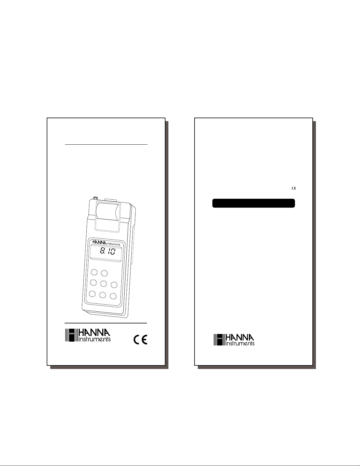
Instruction Manual
HI 9141 - HI 91410
Portable
Printing and Logging
Dissolved Oxygen Meters
HI 91410
MICROPROCESSORLOGGING
DISSOLVEDOXYGEN METER
RANGE
O
0. . . 19.99ppm
ON/OFF
FUNC
CAL
These Instruments are in Compliance with the CE Directives
2
PAPER
TIO
N
UP
DO
PR
IN
T
L
O
2
Dear Customer,
Thank you for choosing a Hanna Instruments
Product.
Please read this instruction manual carefully
before using the instrument.
This manual will provide you with all the neces-
sary information for the correct use of the
instrument, as well as a precise idea of its
versatility in a wide range of applications.
These instruments are in compliance with
directives EN 50081-1 and 50082-1.
TABLE OF CONTENTSTABLE OF CONTENTS
TABLE OF CONTENTS
TABLE OF CONTENTSTABLE OF CONTENTS
Preliminary Examination............................. 1
General Description .................................... 1
Functional Description Probe...................... 3
Functional Description HI9141 ................... 4
Functional Description HI91410.................. 5
Specifications ............................................. 6
Initial Preparation........................................ 7
Calibration ................................................... 9
Taking Measurements .............................. 11
Setting Date, Time, Printing Interval ......... 13
Printing / Recording with HI9141.............. 17
Printing / Logging with HI91410 ............... 19
Altitude Compensation.............................. 23
Salinity Compensation.............................. 24
Temperature Compensation ...................... 24
W
N
G
Probe & Membrane Maintenance ............. 25
Data Transfer to PC.................................. 2 7
Fault Functions ........................................ 29
Memory Organization (HI91410 only) ....... 30
Printer Maintenance.................................. 31
Battery Replacement ................................ 33
Accessories .............................................. 35
Warranty ................................................... 36
CE Declaration of Conformity ................... 37
http://www.hannainst.com
ISO 9000 Certified
Company since 1992
1
2
Page 2
Untitled-22
3
PRELIMINARY EXAMINATION
Remove the instrument from the packing
material and examine it to make sure that no
damage has occurred during shipping. If there
is any damage, notify your Dealer.
Each Printing D.O. meter is supplied complete
with:
• 1.5V AA size batteries (4 pieces)
• DO Probe with 4 m/13' cable (HI 76407/4)
• Membrane cap, 2 pieces (HI 76407A)
• Electrolyte solution, 30 ml (HI 7041S)
• Paper rolls, 5 pieces
• Rugged Carrying case
Note: Save all packing material until you are
sure that the instrument functions
correctly. All defective items must be
returned in the original packing with
the supplied accessories.
GENERAL DESCRIPTION
The HI 9141 and HI 91410 are portable, microprocessor-based, printing (and logging
HI 91410 only) meters for Dissolved Oxygen
measurements.
Housed in a rugged and lightweight case,
with an easy-to-read LCD, they are the first
portable D.O. meters in their category to
incorporate a printer. The printer uses plain,
non-fading paper.
They are capable of storing up to 8,000 readings. These readings can be printed and/or
transferred to a computer system for elaboration or permanent storage (HI 91410 only).
An optional HI 9200 infrared transmitter can
be used to interface the HI 91410 to a com-
puter for data transfer.
Dissolved oxygen and temperature measurements can be performed with lab-grade preci-
3
4
sion in the field (wastewater treatment, fishfarming, water analysis, etc.) as well as in
the laboratory without compromising accuracy.
Dissolved oxygen is indicated in ppm (parts
per million).
Temperature is compensated for by the meter's
ATC circuitry. Salinity compensation in water
allows direct determination of dissolved oxygen in saline waters and the altitude compensation readjusts for the altitude variance.
The dissolved oxygen probe has a membrane
covering the polarographic sensors and a builtin thermistor for temperature measurements
and compensation. This permeable PTFE
membrane isolates the sensor elements from
the testing solution, but allows oxygen to
enter. When a voltage is applied across the
sensor, oxygen that has passed through the
membrane reacts causing a current flow.
4
Page 3
Untitled-22
ON/OFF
PAPER
FUNCTION UP
DOWN
CAL
PRINT
RECORD
6
7
8
9
10
4
5
3
2
1
MICROPROCESSORPRINTING
DISSOLVEDOXYGEN METER
HI 9141
RANGE
O20. . . 19.99ppm
°C 0. . . +50.0°C
5
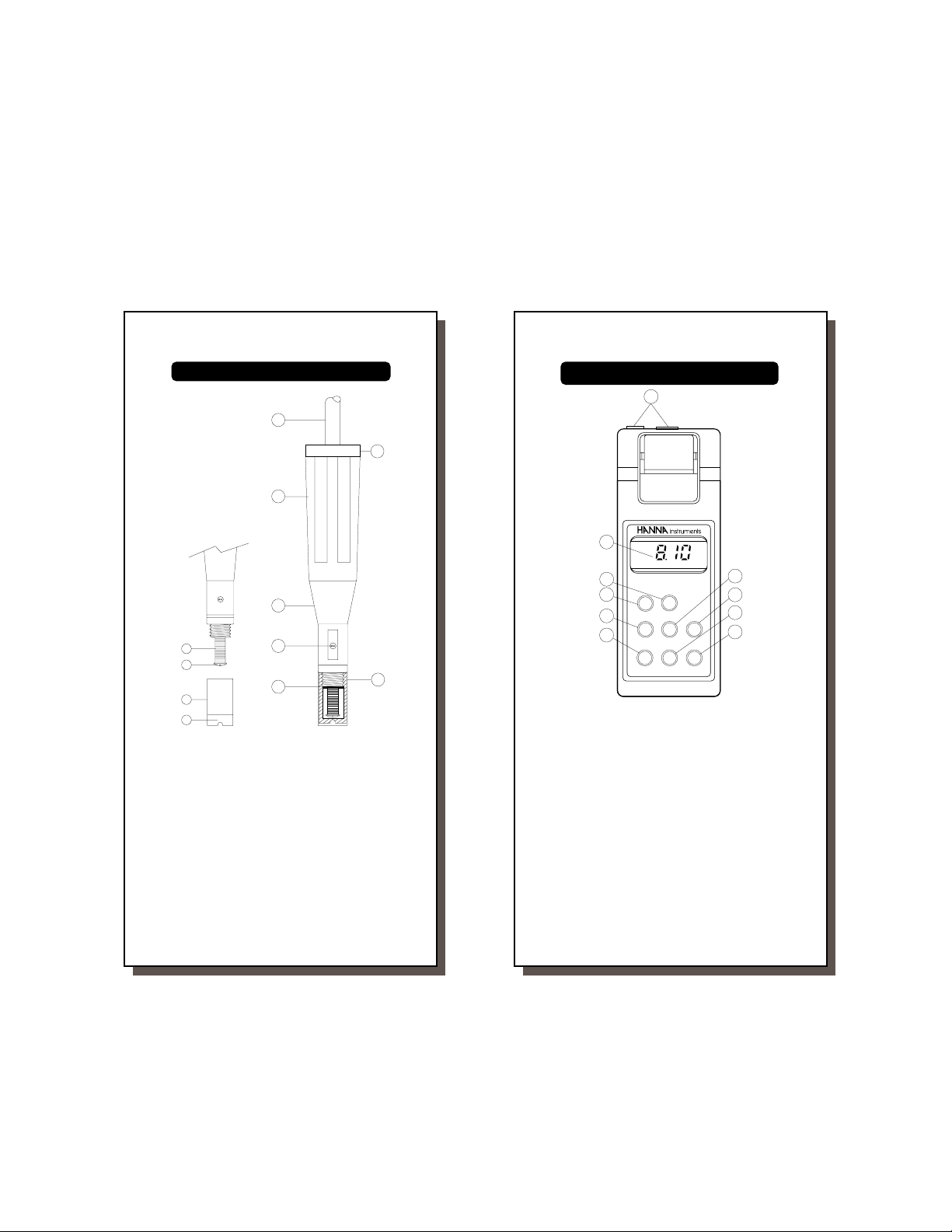
FUNCTIONAL DESCRIPTION PROBE
3
1
4
4
7
8
10
9
5
6
2
6
FUNCTIONAL DESCRIPTION HI9141
1. Probe connector and socket for adapter
2. UP key, to set date, time, printing interval,
values for altitude and salinity compensation
1. D.O. Probe
2. Protective Cap
3. Watertight Shielded Cable
4. Polypropylene Probe Body
5. Temperature Sensor
6. O-Ring Seal
7. Silver Chloride Anode
8. Platinum Cathode (sensor)
9. Oxygen Permeable PTFE
Membrane
10. Membrane Cap
5
3. DOWN key, to set date, time, printing
interval, values for altitude and salinity
compensation
4. PRINT key, to obtain a printout
5. RECORD key, to enter the recording mode
6. Liquid Crystal Display
7. PAPER key, to move the paper up
8. ON/OFF key, to turn the meter on or off
9. FUNCTION key, to select the D.O. or
temperature mode and for compensation
selection
10. CAL key, to enter or exit calibration mode.
6
Page 4
Untitled-22
7
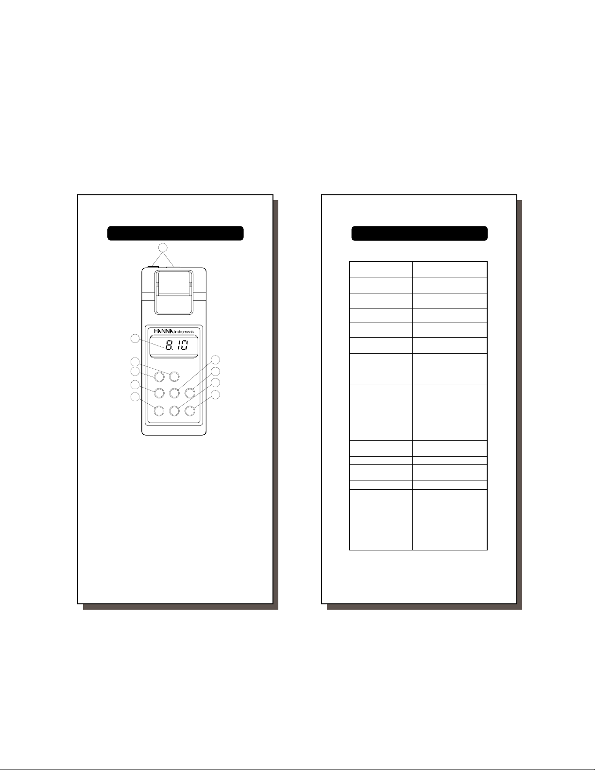
FUNCTIONAL DESCRIPTION HI91410
1
6
HI 91410
7
MICROPROCESSOR LOGGING
DISSOLVEDOXYGEN METER
8
9
10
1. Probe connector and socket for adapter
2. UP key, to set date, time, printing interval,
values for altitude and salinity compensation
3. DOWN key, to set date, time, printing interval, values for altitude and salinity compensation
4. PRINT key, to obtain a printout
5. LOG key, to enter or exit the logging mode
6. Liquid Crystal Display
7. PAPER key, to move the paper up
8. ON/OFF key, to turn the meter on or off
9. FUNCTION key, to select the D.O. or
temperature mode and for compensation
selection
10. CAL key, to enter or exit calibration mode.
ON/OFF
FUNCTION UP
CAL
PAPER
PRINT
RANGE
O20. . . 19.99ppm
°C 0. . . +50.0°C
7
DOWN
LOG
8
SPECIFICATIONS HI9141 & HI91410
Range DO 0.00 to 19.99 ppm
Resolution DO 0.01 ppm
Accuracy DO 1.5% of full scale
Typical EMC DO ±0.6 ppm
Deviation Temp. ±3°C
Calibration Automatic in saturated air
Temperature Automatic from 0 to 30°C
Compensation (32 to 86°F)
2
3
4
5
Altitude Compensation 0 to 1,900 m (6,230')
Salinity Compensation 0 to 40 g/l
Power Supply 4 x 1.5V AA batteries,
Printer Low-power impact type belt,
Printing /Logging 1, 2, 5, 10, 15, 30,
Interval 60, 120, 180 minutes
Environment 0 to 50°C; 95% RH
Dimensions 220 x 82 x 66 mm
Shipping Weight 1.7 kg (3.8 lb.)
Response Time The response time is about 20
Temp. 0.0 to 50.0°C
Temp. 0.1°C
Temp. ±0.5 °C
at 100%
Resolution 100 m (328')
Resolution 1 g/l
approx. 70 hours of life;
Auto shut-off after 4 hours.
Power socket for
12VDC adapter
14 characters per line using
38mm plain paper
(8.7 x 3.2 x 2.6")
seconds for a 95% reading at
a constant temperature of
25°C. The response time for
low oxygen readings or at
low temperature is approximately 40 seconds. Allow
more time to obtain more accurate readings.
8
Page 5
Untitled-22
S
9
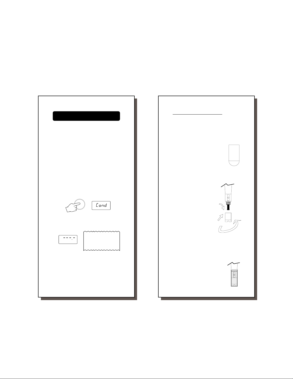
INITIAL PREPARATION
Each meter is supplied complete with batteries. Remove the back cover, unwrap the batteries and install them while paying attention
to the polarity (see also page 33).
To prepare the instrument for use, connect
the D.O. probe to the meter securely by
aligning the pins with the socket located on
the top of the meter, pushing the plug in and
tightening the threaded ring. Follow the "Initial Probe Preparation" procedure explained
on page 8.
To switch the meter on, press the ON/OFF
key and "Cond" appears on the display to
inform that the probe is in the auto-conditioning (polarization) mode. Once the "Cond" disappears, the instrument can be calibrated
(see page 9).
ON/OFF
If the probe is disconnected, the meter will
display "°C ---.-" and print "---- ppm" and
"----°C" to alert the user.
°C
This also indicates the possibility of a broken
probe cable.
To maximize battery life, the display is automatically switched off after 4 hours of nonuse. However, the meter will continue to monitor
dissolved oxygen and temperature (if in the
recording/logging mode) .
<>
0009 *00.50
9
14-01-96
---- ppm
---- ° C
10
INITIAL PROBE PREPARATION
All probes shipped from Hanna Instruments
are dry. To hydrate the probe and prepare it
for use, connect it to the meter and proceed
as follows.
1. Remove the red and black plastic cap. This cap is for shipping
purposes and can be thrown
away.
2. Wet the sensor by soaking the
bottom 2½ cm (1") of the probe
in electrolyte (HI 7041S) for
5 minutes.
3. Rinse the membrane cap (HI 76407A supplied in the kit with the meter) with electrolyte solution
while shaking it
gently. Refill with
clean electrolyte
solution.
4. Gently tap the
sides of the membrane cap with
your finger tip to
ensure that no air
bubbles remain
trapped. To avoid
damaging the
membrane, do not
tap the membrane
directly on the bottom.
5. Make sure that the rubber O-ring sits properly inside the membrane cap.
6. With the sensor facing down, slowly screw
the cap clockwise. Some electrolyte will overflow.
When not in use, place the protective cap supplied in the kit with the
meter.
FILL FIRST
THEN TAP
10
hipping
cap
black
red
THEN SCREW
BACK ON
Page 6
Untitled-22
11
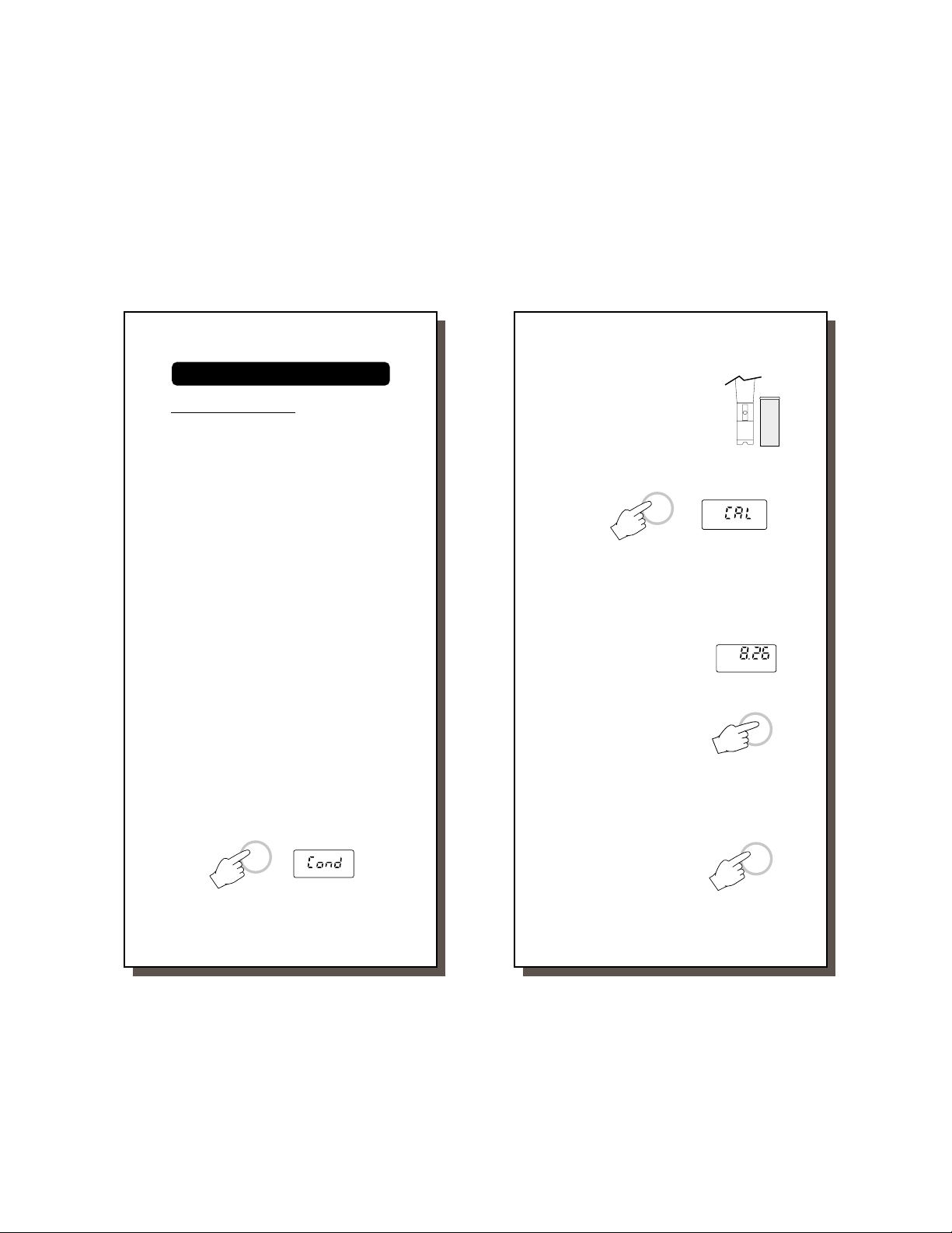
CALIBRATION
PROBE POLARIZATION
The probe is under polarization with a fixed
voltage of approximately 800 mV.
Probe polarization is essential for stable measurements with the same recurring degree of
accuracy.
With the probe properly polarized, oxygen is
continually "consumed" when it passes
through the sensitive diaphragm and dissolves
in the electrolyte solution contained in the
probe.
If polarization is interrupted, the electrolyte
solution continues to be enriched with oxygen until it reaches an equilibrium with the
surrounding solution.
Whenever measurements are taken with a
non-polarized probe, the oxygen level revealed
is both that of the tested solution as well as
that present in the electrolyte solution. This
reading is incorrect.
The calibration of this instrument is very simple
and is recommended every time the meter is
turned on.
• Make sure the probe is ready for measurements (see page 8), i.e. the membrane cap is filled with electrolyte and the
probe is connected to the meter and properly polarized.
• Switch the meter on by pressing the ON/
OFF key and "Cond" appears on the display to inform that the probe is in autoconditioning (polarization) mode.
ON/OFF
• Once the "Cond" disappears, the instrument can be calibrated.
11
12
• For an accurate calibration, it
is recommended to wait for 5
or 10 minutes to ensure precise conditioning of the probe.
• Remove the protective cap.
• Press the CAL key. "CAL" appears on the
primary display to indicate that the instrument is in calibration mode.
CAL
• The instrument will automatically standardize itself to the actual saturation value and
after approximately 1 minute will show the
value in ppm corresponding to the maximum oxygen level soluble in water at that
particular temperature and at the conditions of altitude and salinity previously set. Once the
value in ppm is displayed,
the calibration is completed.
• Press the FUNCTION key
and make sure F1 and
F2 are set to the appropriate altitude and salinity values (see pages 23-24).
Notes: • The instrument must also be cali-
brated whenever the probe, the membrane or the electrolyte solution are
changed.
• If you want to exit
the calibration mode
during the calibration, press the CAL
key again.
12
FUNCTION
CAL
Page 7

Untitled-22
13
TAKING MEASUREMENTS
Make sure the meter has been
calibrated (see page 9) and
the protective cap has been
removed. Immerse the tip of
the probe in the sample to be
tested.
Make sure the temperature sensor is also
immersed.
Allow approximately one minute for the meter
to stabilize and read the mg/l (ppm) value of
dissolved oxygen on the display.
For accurate dissolved oxygen measurements
a water movement of 0.3 m/sec is required
at a minimum. This is to ensure that the
oxygen-depleted membrane surface is constantly replenished. A moving stream will provide adequate circulation.
During field measurements, this condition may
be met by manually agitating the probe. Accurate readings are not possible while the
liquid is at rest.
During laboratory measurements, the use of
a magnetic stirrer to ensure a certain velocity
in the fluid is recommended. In this way,
errors due to the diffusion of the oxygen
present in the air in the solution are reduced
to a minimum.
At all times, the time necessary for thermal
equilibrium to occur between the probe and
the measurement sample must be allowed (a
few minutes if the temperature difference is
only several degrees).
ppm READINGS
The ppm readings allow the
user to read the concentration of the dissolved oxygen
13
14
directly on the display expressed in ppm
(mg/l).
If the sample contains significant salinity
concentration or if you are performing the
measurements at an altitude different from
sea level, the readout values must be corrected, taking into account the lower degree of oxygen solubility in such occasions
as explained on pages 23-24.
Remember to set the altitude and/or the
salinity before taking ppm measurements.
The meter will automatically compensate
for these factors.
TEMPERATURE READINGS
The probe has a built-in temperature sensor.
Press the FUNCTION key to display the
measured temperature.
°C
FUNCTION
Allow the probe to reach the thermal equilibrium before taking any measurement. Thermal equilibrium can take several minutes to
be reached. The greater the difference between the temperature at which the probe
was stored and the temperature of the sample,
the longer the time will be.
If "°C ---.-" is displayed, it indicates that the
D.O. probe is not properly connected. This
also indicates the possibility of a broken probe
cable.
°C
14
Page 8

Untitled-22
15
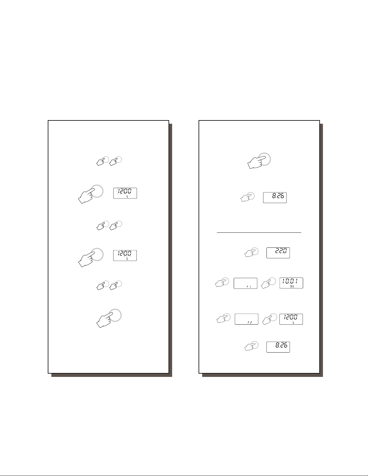
SETTING DATE, TIME AND
PRINTING INTERVAL
Turn the instrument on by
pressing the ON/OFF key and
wait for the "Cond" symbol to
disappear.
Press the FUNCTION key twice and the display will show "F1" on the secondary display.
FUNCTION
Press the CAL key and the display will show
the date setting.
CAL
Press the CAL key again and the year will
start blinking on the secondary LCD.
CAL
Use the UP or the DOWN keys to select the
year.
When the correct year is selected, press the
CAL key once. The month will start blinking.
16
Select the month by using the UP or the
DOWN keys.
UPDOWN
Press the CAL key, the day will start blink-
ON/OFF
DATE
DATE
UPDOWN
ing.
DATE
CAL
Use the UP or the DOWN keys to select the
correct day.
UPDOWN
Press the CAL key to confirm the selected
date and press the FUNCTION key to leave
the date setting mode.
CAL
FUNCTION
Press the FUNCTION key again to display
"F2" on the secondary display.
FUNCTION
Press the CAL key and the display will show
the time and the printing interval setting.
TIME
CAL
INTV
Press the CAL key again and the printing
interval will start blinking.
CAL
DATE
15
CAL
16
TIME
INTV
Page 9
Untitled-22
17
Any interval can be selected from 1, 2, 5, 10,
15, 30, 60, 120 or 180 minutes by using the
UP and the DOWN keys.
Set the desired interval by pressing the CAL
key once and the hour will start blinking.
CAL
To select the hour, press the UP or the
DOWN keys (24 hour clock).
Press the CAL key once, the minutes will
start blinking.
CAL
Use the UP or the DOWN keys to select the
minutes.
Press the CAL key to confirm the selected
time and printing interval.
18
Press the FUNCTION key to leave the time
setting mode.
UPDOWN
Press the FUNCTION key again to display
D.O. readings.
TIME
INTV
Your time, date and printing interval are now
set and stored in the memory even when the
display is switched off.
UPDOWN
TO VIEW DATE / TIME / TEMPERATURE
To view the temperature press the FUNCTION key.
TIME
INTV
To view the date first, press the FUNCTION
key to display "F1" and then the CAL key.
UPDOWN
FUNCTION
To view the time first, press the FUNCTION
key until the display shows "F2" and then the
CAL key. This also displays the selected
prinitng interval.
FUNCTION
FUNCTION
FUNCTION
°C
CAL
DATE
TIME
CAL
FUNCTION
INTV
CAL
Press the FUNCTION key until the display
returns to the D.O. readings.
FUNCTION
17
18
Page 10

Untitled-22
19
PRINTING / RECORDING
WITH HI 9141
To print the measured values
press the PRINT key.
The printout provides the following information:
a- Running sample number
b - Date (DD-MM-YY)
c - Time (HH-MM)
d - D.O. value in ppm.
e - Temperature value
in °C.
RECORDING MODE (PROGRAMMED
PRINTOUTS)
Press the RECORD key to enter the recording mode. The log number and the interval
time will appear for a few seconds on the
display to indicate the correct operational
mode.
The meter will print the measurement taken in that moment, and
will print at the interval selected
thereafter until the RECORD key
is pressed.
Each printout provides the following information:
a- A running log number
b- A running sample number (in that particu-
lar log)
0015 *00.50
<>
LOG
RECORD
14-01-96
--02-- 0005M
0003 *15.50
<>
8.5 ppm
25.4 ºC
PRINT
14-01-96
8.1 ppm
20.4 °C
RECORD
a
b
c
d
e
f
g
20
c - Date (DD-MM-YY)
d- Printing interval indicator in minutes
e- Time (HH.MM)
f - D.O. value in ppm
g- Temperature value in °C.
When the meter is in recording mode "LOG" is displayed
a
b
c
d
e
on the bottom left corner of
the LCD with the temperature
value on the primary display.
Notes:
• It is recommended to use the external power
supply (HI710005 or HI710006) during
recording mode, especially when many
printouts are required.
• Before proceeding with recording, make
sure there is enough paper for your
measurements. When the paper is finished the meter will not advise the operator and the printouts could be lost.
• It is possible to insert a new paper roll
during recording session (see page 31).
• If the PRINT key is pressed while
still in recording mode, a printout is produced without affecting
the running sample number.
• Once in recording mode, the
printing interval cannot be
changed. Exit the recording
mode first (pressing the
RECORD key) before setting the new interval (see page 13).
TO STOP RECORDING
In order to quit the recording mode, press the
RECORD key. This will generate a recording
exit status printout.
Log number
Total sample number
==07== 0005M
°C
LOG
10-01-96
0016 *16.25
#1 20.0 °C
#2 57.3 °C..
PRINT
RECORD
LOG EXIT
Date/Time
19
20
Page 11

Untitled-22
21
PRINTING / LOGGING
WITH HI 91410
To print the measured values
shown on display, press the
PRINT key.
This function can be activated
in normal operation mode as
well as during logging (see below).
When in measurement mode, the printout
provides the following information:
a- Running sample number
b- Date (DD-MM-YY)
c - Time (HH-MM)
d- D.O. value in ppm.
e- Temperature
value in °C.
LOGGING MODE
This function is suggested when remote measurements have to be taken automatically
without the necessity of an operator and for a
long period of time. In this mode data will be
stored directly into memory.
Set the appropriate logging interval (see
page13).
Press the LOG key to enter the logging mode.
The log number and page number will appear
for a few seconds on the display to indicate
the correct operational mode.
LOG
The printer will print a complete set of data
and the "LOG" symbol will appear on the
bottom left corner of the LCD.
0001 *16.50
<>
LOG
21
PRINT
14-01-96
8.95 ppm
20.4 °C
Log number
Page Number
22
The printout provides the following information:
a- A running log number
b- Running sample number (in that particular
log)
c - Date (DD-MM-YY)
d- Printing interval indicator in minutes
e- Time (HH-MM)
f - D.O. value in
ppm.
g- Temperature
value in °C.
14-01-96
--02-- 0005M
0001 *16.50
<>
8.95 ppm
20.4 °C
To continue logging without printing, press
a
b
c
d
e
now the CAL key and the "LOG" symbol on
display will start to blink and no printout will
be generated.
LOG
CAL
If you wish to restart printing press the CAL
key again.
Notes:
• Once in the logging mode,
the interval cannot be
changed. Exit the logging
mode first (pressing the
LOG key) before setting
the new interval.
• If the PRINT key is pressed
while in logging mode, a
printout is produced without affecting the running
sample number.
22
PRINT
a
b
c
d
e
f
g
LOG
Page 12

Untitled-22
23
LOGGING MODE WITH PRINTING
This function is suggested when an immediate report of the measurement is required in
addition to the recording of the data into
memory.
Press the LOG key to enter the logging mode.
The log number and page number will appear
for a few seconds on the display to indicate
the correct operational mode.
LOG
The printer will print a complete set of data
and the "LOG" symbol will appear on the
secondary display.
Each printout provides the following information:
a- A running log number
b- Running sample number (in that particular
log)
c - Date (DD-MM-YY)
d- Printing interval indicator in minutes
e- Time (HH-MM)
f - D.O. value in ppm.
g- Temperature value in °C.
--03-- 0010M
<>
0001 *19.10
LOG
14-01-96
8.02 ppm
22.1 °C
23
Log number
Page Number
a
b
c
d
e
f
g
24
It is always possible to switch from the logging with printing function to the logging function. Press the CAL key and the "LOG" symbol will start to blink to indicate that the data
are now stored only into memory.
CAL
Notes:
• It is recommended to use the external power
supply (HI710005 or HI710006) during
logging with printing mode, especially when
many printouts are required.
• Before proceeding with logging with printing, make sure there is enough paper for
your measurements. When the paper is
finished the meter will not advise the operator and the printouts could be lost. If
this happens, data will continue to be
stored into memory.
• It is possible to insert a new paper roll
during logging session (see page 31).
• Once in the logging mode,
the interval cannot be
changed. Exit the logging
mode first (pressing the
LOG key) before setting
the new interval.
• If the PRINT key is pressed
while in logging mode, a
printout is produced without affecting the running
sample number.
TO STOP LOGGING
Press the LOG key, this will generate a log
exit status printout.
Log number
Total sample number
LOG
- -09- - 0001M
==07== 0005M
0016 *20.00
<>
0016 *16.25
#1 20.0 °C.
24
14-01-96
10-01-96
LOG
PRINT
LOG EXIT
Date/Time
Page 13

Untitled-22
25
ALTITUDE COMPENSATION
Press the FUNCTION key twice and “F1” will be
displayed.
FUNCTION
Use the UP and the DOWN keys to set the
altitude between 1 and 1900 m, in steps of
100 m (1 meter = 3.28 feet).
Altitude affects D.O. concentration decreasing
its value. The following table reports the maximum oxygen solubility at various temperatures
and altitudes.
°C
0
2
4
6
8
10
12
14
16
18
20
22
24
26
28
30
32
34
36
38
40
Altitude, Meters above Sea Level
0 m
300 m
600 m
14.6
14.1
13.3
12.7
12.0
11.4
10.9
10.4
13.6
12.9
12.2
11.6
11.0
10.5
10.1
9.9
9.6
9.7
9.2
9.2
8.7
8.8
8.5
8.4
8.1
8.1
7.8
7.8
7.5
7.5
7.3
7.2
7.0
7.1
6.8
6.9
6.6
6.6
6.3
6.4
6.2
6.2
6.0
13.8
13.1
12.4
11.8
11.3
10.8
10.3
9.9
9.5
9.1
8.7
8.4
8.1
7.8
7.5
7.3
7.1
6.8
6.6
6.4
900 m
13.2
12.4
11.9
11.2
10.6
10.2
9.7
9.3
8.9
8.6
8.2
7.8
7.5
7.3
7.0
6.8
6.6
6.4
6.1
5.9
5.8
1200 m
25
12.7
12.0
11.4
10.8
10.3
9.8
9.4
9.0
8.6
8.3
7.9
7.7
7.3
7.0
6.8
6.5
6.4
6.2
5.9
5.7
5.6
UPDOWN
1500 m
12.3
11.6
11.0
10.4
9.9
9.5
9.1
8.7
8.3
8.0
7.7
7.3
7.1
6.8
6.6
6.3
6.1
6.0
5.7
5.6
5.4
1800 m
11.8
11.2
10.6
10.1
9.6
9.2
8.8
8.3
8.0
7.7
7.4
7.1
6.8
6.6
6.3
6.1
5.9
5.8
5.5
5.4
5.2
°F
32.0
35.6
39.2
42.8
46.4
50.0
53.6
57.2
60.8
64.4
68.0
71.6
75.2
78.8
82.4
86.0
89.6
93.2
96.8
100.4
104.4
26
SALINITY COMPENSATION
Press the FUNCTION key until “F2” will be
displayed.
FUNCTION
Use the UP and DOWN keys to set the salinity
between 0 and 40 g/l.
UPDOWN
Salinity affects D.O. concentration decreasing
its value. Below is the table showing the maximum solubility of oxygen at various temperature
and salinity.
°C
10
12
14
16
18
20
22
24
26
28
The D.O. probe has a built-in sensor for
temperature so that the D.O. readings are
automatically compensated for temperature
effects.
Salinity (g/l) at Sea Level
0 g/l
10 g/l
20 g/l
11.3
10.6
10.1
7.4
9.9
9.5
9.7
9.1
9.3
8.7
8.9
8.4
8.5
8.0
7.8
8.2
7.9
7.5
7.6
7.2
7.0
10.8
10.3
9.9
9.5
9.1
8.7
8.4
8.1
7.8
TEMPERATURE COMPENSATION
26
30 g/l
9.3
8.9
8.6
8.2
7.9
7.6
7.3
7.1
6.8
6.6
35 g/l
9.0
8.6
8.3
8.0
7.6
7.4
7.1
6.9
6.6
6.4
°F
50.0
53.6
57.2
60.8
64.4
68.0
71.6
75.2
78.8
82.4
Page 14

Untitled-22
27
PROBE AND MEMBRANE MAINTENANCE
The oxygen probe body is made of reinforced
plastic for maximum durability.
A thermistor temperature sensor provides temperature measurements of the sample tested.
It is always recommended that the protective
cap be kept on the probe when the probe is
not in use to provide protection against damage and dirt.
To replace the membrane or refill with
electrolyte, proceed as follows:
• Remove the protective
cap by gently twisting
and pulling it off the
body of the probe (see
fig. 1).
• Unscrew the membrane
cap by turning it counterclockwise (see fig.2).
• Wet the sensor by
soaking the bottom 2½
cm (1") of the probe in
electrolyte (HI 7041S)
for 5 minutes.
• Rinse the new membrane cap (HI 76407A)
supplied with the meter
with electrolyte solution
while shaking it gently. Refill with clean
electrolyte solution.
• Gently tap the sides of
the membrane cap with
your finger tip to ensure that no air bubbles
remain trapped. Do no
directly tap the bottom
with your finger as this
27
TWIST
AND
PULL
fig. 1
UNSCREW
fig. 2
28
will damage the membrane.
• Make sure that the rubber O-ring sits
properly inside the membrane cap.
• With the sensor facing down, slowly
screw the membrane cap clockwise.
Some electrolyte will overflow.
The Platinum cathode (#8 in the Functional
Description at page 3) should always be
bright and untarnished. If it is tarnished or
stained, which could be due to contact
with certain gases or extended use with a
loose or damaged membrane, the cathode
should be cleaned. You can use a clean
lint-free cardboard or cloth. Rub the cathode very gently side to side 4-5 times.
This will be enough to polish and remove
any stains without damaging the platinum
tip. Afterwards, rinse the probe with deionized or distilled water and install a new
membrane cap using fresh electrolyte and
follow the steps above. Re-calibrate the
instrument.
Important: in order to have accurate and
stable measurements, it is important that
the surface of the membrane is in perfect
condition. This semipermeable membrane
isolates the sensor elements from the environment but allows oxygen to enter. If any
dirt is observed on the membrane, rinse
carefully with distilled or deionized water. If
any imperfections still exist, or any damage is evident (such as wrinkles or tearsholes), the membrane should be replaced.
Make sure that the O-Ring sits properly in
the membrane cap.
28
Page 15

Untitled-22
29
DATA TRANSFER TO PC
HI91410 contains infrared emitting circuitry.
Press the FUNCTION key until "F2" is displayed on the secondary LCD.
FUNCTION
Place your data-logger on the HI9200 Infrared Transmitter (ensuring that the two infrared
LEDs are placed on top of each other) and
the memory can then be downloaded to your
PC through the HI9200's RS232 port.
During the data transfer the
instrument displays the message "r 232".
30
Data transmission from the instrument to the
PC is now much easier with new HI92000
®
Windows
fered by Hanna Instruments.
HI 92000 allows you to use the powerful
means of the most spread sheet programs
(e.g.Excel
favorite spread sheet and open the file downloaded by HI 92000. It is possible to make
any elaboration available with your software
(e.g. graphics, statistical analysis).
User friendly, HI 92000 offers a variety of features and has an on line help to support you
throughout any situation.
To install HI 92000 you need a 3.5" drive and
a few minutes to follow the instructions conveniently printed on the disk label.
compatible application software of-
©
, Lotus 1-2-3©). Simply run your
Using the HI9200 Infrared Transmitter, all
recorded data can be fed to your Personal
Computer for easy reproduction, storage or
elaboration without the interference of cables
or cords between the meter and the transmitter.
29
Windows® is registered Trademark of "Microsoft Co."
©
Excel
Copyright of "Microsoft Co."
©
Lotus 1-2-3
Copyright of "Lotus Co."
30
Page 16

Untitled-22
31
FAULT FUNCTIONS
HI9141 and HI91410 are factory programmed
to automatically diagnose a fault. This is
displayed with error codes on the LCD.
Error codes:
PEr 0, PEr 1, PEr 2 = Short circuit on the
system, the meter should be returned
for repair (see Warranty section).
PEr 3 = Printer mechanism fault - repair
needed (see Warranty section).
PEr 4 = Printer clutch jammed - reset the
printer (see page 32).
PEr 9 = Printer jammed - reset the printer
(see page 32).
32
MEMORY ORGANIZATION
(HI91410 ONLY)
Capacity: 8,000 data samples, divided into
16 pages.
Data capacity per page:
500 data samples.
Each time a new logging period starts, it
automatically starts from a new page.
If “LOGGING” is still on, and the available
page is “0” the meter will overwrite the first
LOT DATA in the existing meter memory.
During logging the meter automatically returns to the oldest page in the memory and if
it contains data, it will overwrite it. In this
case the first log will not correspond to the
oldest set of data.
It is recommended to periodically “clean” the
memory. Save the data with a PC if you need
to keep a record and then disconnect the
batteries for about 1 minute. If you do this,
remember to re-set the date, time, altitude
and salinity.
WARNING
Data are stored into memory until batteries
are removed.
If replacement of the batteries is needed and
data are not to be lost, plug the external
power supply in and proceed with batteries
replacement as described on page 33. Only
once the batteries have been replaced it is
possible to unplug the power supply without
loosing the stored data.
31
32
Page 17

Untitled-22
33
PRINTER MAINTENANCE
TO CHANGE THE INK CARTRIDGE
When printouts become faint, it might be
necessary to change the ink cartridge. Contact your Hanna authorized center.
TO INSERT THE PAPER ROLL
The HI 9141 and HI91410 use plain paper
rolls 38 mm large. To insert a new roll is very
easy.
Open the paper cover pulling gently on the tab.
Take the carton cylinder out.
Insert the paper edge in the printer slot and
feed the printer by pressing the PAPER key.
34
Allow approximately 5 cm (2") to exit from
the printer and replace the paper cover.
TO RESET THE PRINTER
Take the battery
cover off by removing the screws. Using a pencil press
the black button.
This will reset the
printing mechanism.
Before replacing the
battery cover investigate the cause of
the printer jam (e.g.
the paper caught
under the cover preventing the printer
from advancing paper feed).
Replace the battery
cover and secure
the screws.
-
1.5V
+
-
1.5V
+
-
1.5V
1.5V
+
SCREW
+
POTS
-
RESET
PAPER
33
34
Page 18

Untitled-22
35
BATTERY REPLACEMENT
If "LO BAT" appears on the
display, it indicates that the
batteries are running down.
If it blinks during printing, it means that 200
printouts can be made before the batteries
are exhausted. When there is only sufficient
power for 100 printouts, the "LO BAT" sign is
displayed continuously on the LCD.
Battery replacement must only take place in
a non hazardous area using the battery types
specified in this instruction manual (see
page 35).
In order to replace
run down batteries,
simply remove the
two screws on the
rear cover of the instrument and replace the four 1.5V
AA batteries with
new ones, paying
attention to the correct polarity.
A 12VDC power
source can also be
used to power the
unit (see the Accessories section
page 35).
Note: The instrument uses the following con-
figuration.
36
It is recommendable to purchase Hanna In-
struments HI 710005 and HI710006 voltage
°C
LO BAT
-
1.5V
+
-
1.5V
+
-
1.5V
1.5V
+
SCREW
+
POTS
-
RESET
adapters that use the proper polarity configuration.
HI9141 and HI91410 can also be used with
other adapters. In this case, remember to
check the correct polarity of your adapter
before connecting it to the meter.
WARNING: In HI91410, if the external power
supply and batteries are disconnected, all stored data will be
erased. Always apply external
power supply to the instrument
when changing low batteries to
prevent data from being lost.
+
-
35
36
Page 19
Untitled-22
37
ACCESSORIES
HI 7041S Refilling Electrolyte Solution,
HI 710005 115 VAC to 12 VDC power
HI 710006 230 VAC to 12 VDC power
HI 710034 Plain paper spare roll (10 pcs)
HI 710035 Spare ink cartridge (1 pc)
HI 721308 1.5V AA alkaline battery (10
HI 76407/10 Spare probe with 10 meters
HI 76407/20 Spare probe with 20 meters
HI 76407A/P 5 spare membranes
HI 9200 Infrared Transmitter
HI 92000/16 Windows
HI 92000/32 Windows
MANDOPRNR1 Instruction manual
30 ml
adapter
adapter
pcs)
(33') cable
(66') cable
®
software for data transfer to PC
®
95 compatible soft-
ware for data transfer to PC
3.11 compatible
38
WARRANTY
All Hanna Instruments meters are warranted
for two years against defects in workmanship
and materials when used for their intended
purpose and maintained according to the instructions. The probes are warranted for a
period of six months.
This warranty is limited to repair or replacement
free of charge.
Damages due to accident, misuse, tampering
or lack of prescribed maintenance are not covered.
If service is required, contact the dealer from
whom you purchased the instrument. If under
warranty, report the model number, date of
purchase, serial number and the nature of the
failure. If the repair is not covered by the warranty, you will be notified of the charge for repair
or replacement.
If the instrument is to be returned to Hanna
Instruments, obtain a Return Goods Authorization from the Customer Service Department first
and then send it with shipment cost prepaid.
When shipping any instrument, make sure it is
properly packaged for complete protection.
To validate your warranty, fill out and return the
enclosed warranty card within 14 days from the
date of purchase.
Windows® is registered Trademark of "Microsoft Co."
37
All rights are reserved. Reproduction in whole or
in part is prohibited without the written consent
of the copyright owner.
Hanna Instruments reserves the right to modify
the design, construction and appearance of
its products without advance notice.
38
Page 20

Untitled-22
39
CE DECLARATION OF CONFORMITYCE DECLARATION OF CONFORMITY
CE DECLARATION OF CONFORMITY
CE DECLARATION OF CONFORMITYCE DECLARATION OF CONFORMITY
DECLARATION OF CONFORMITY
We
Hanna Instruments Srl
V.le delle industrie 12
35010 Ronchi di Villafranca (PD)
ITALY
herewith certify that the dissolved oxygen meters
have been tested and found to be in compliance with the following regulations:
IEC 801-2 Electrostatic Discharge
IEC 801-3 RF Radiated
IEC 801-4 Fast Transient
EN 55022 Radiated, Class B
Date of Issue: 28-11-1995
HI 9141 HI 91410
D.Volpato - Engineering Manager
On behalf of
Hanna Instruments S.r.l.
40
PRINTED IN ITALY
MANDOPRNR1
02/96
Recommendations for Users
Before using these products, make sure that they are entirely suitable for the
environment in which they are used.
Operation of this instrument in residential area could cause unacceptable interferences to radio and TV equipments, requiring the operator to take all necessary steps
to correct interferences.
Any variation introduced by the user to the supplied equipment may degrade the
instrument's EMC performance.
To avoid electrical shock, do not use these instruments when voltages at the
measurement surface exceed 24VAC or 60VDC.
To avoid damages or burns, do not perform any measurement in microwave ovens.
In particular cases the meters could turn off. In such cases, the meters can be turned
on by pressing the ON/OFF key.
37
39
http://www.hannainst.com
40
 Loading...