

Page 1
Instruction Manual
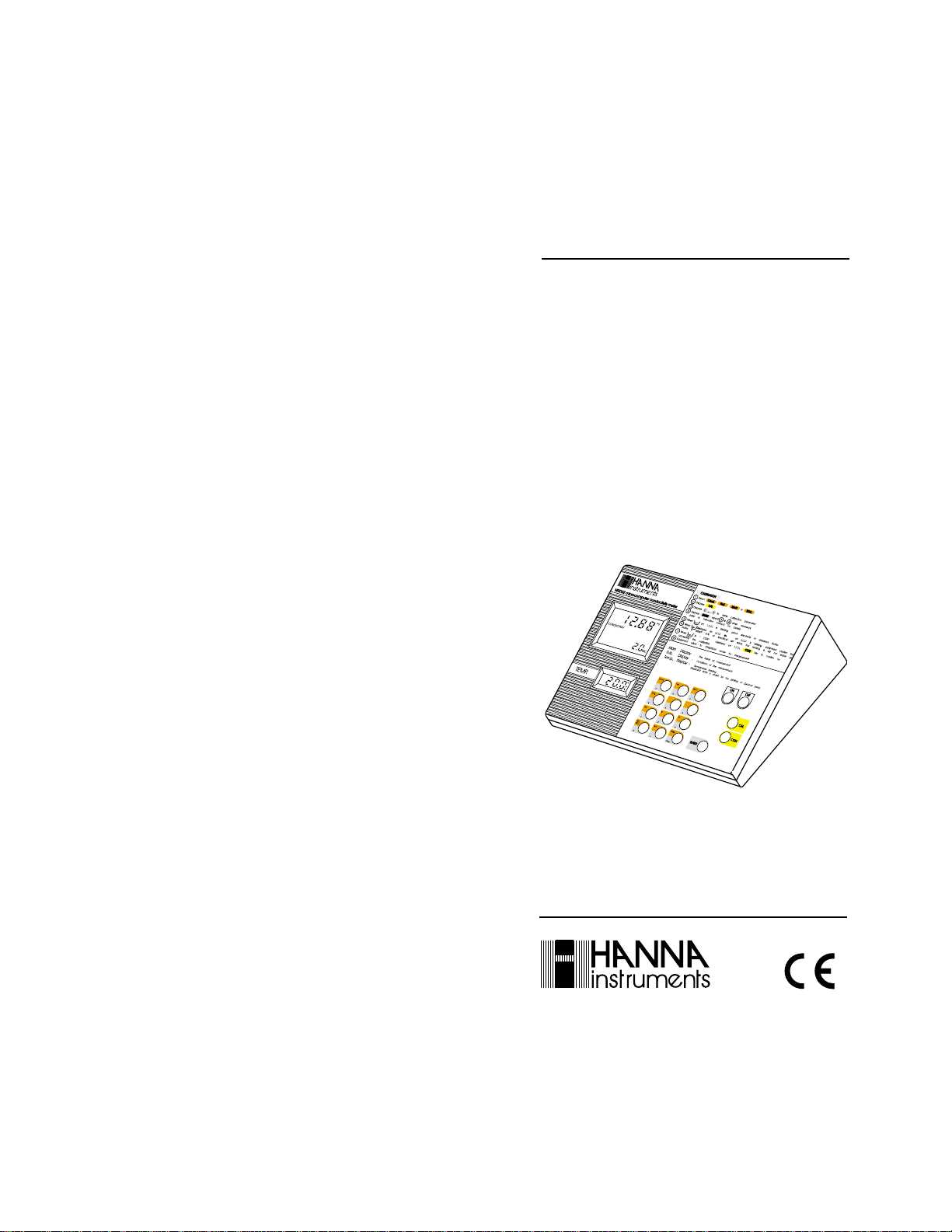
HI 9032
Microprocessor Bench
Conductivity/TDS/NaCl
Fertilizer/°C/°F Meter
with RS 232
These Instruments are in Compliance with the CE Directives
http://www.hannainst.com
Page 2

ins
e
rum n
s
Dear Customer,
Thank you for choosing a Hanna Instruments
Product.
Please read this instruction manual carefully
before using the instrument.
This manual will provide you with all the neces-
sary information for the correct use of the
instrument, as well as a precise idea of its
versatility in a wide range of applications.
This instrument is in compliance with CSA, UL
and (EN 50081-1 and EN 50082-1) direc-
tives.
TABLE OF CONTENTS
Preliminary Examination ............................. 3
General Description..................................... 3
The Front Panel .......................................... 5
Liquid Crystal Displays................................ 7
The Rear Panel ........................................... 8
Specifications ........................................... 10
Operational Guide ......................................11
Conductivity Calibration ............................. 21
NaCl Calibration ........................................ 31
Fertilizer Calibration .................................. 35
Setting T emperature .................................. 40
Setting T emperature Coefficient................. 42
Setting TDS Factor ................................... 45
Programs .................................................. 47
Interface with PC ....................................... 54
Probe Maintenance ................................... 59
Accessories.............................................. 60
Warranty ................................................... 62
CE Declaration of Conformity .................... 63
ISO 9000 Certified
Company since 1992
PRELIMINARY EXAMINATION
Remove the instrument from the packing material and examine it to make sure that no
damage has occurred during shipping. If there
is any damage, notify your Dealer.
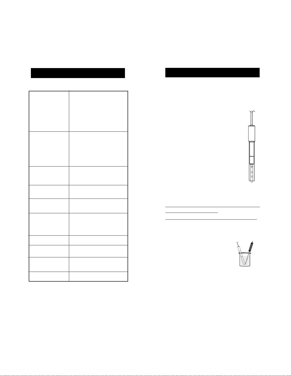
Each HI 9032 bench meter is supplied complete with:
• HI 7669/2W Temperature Probe
• HI 7686 Conductivity Probe
• External Power Supply (HI710005 or
HI710006)
• HI 76405 Electrode Holder
• Dust Cover
Note: Save all packing material until you are
sure that the instrument functions correctly. All defective items must be returned in the original package together
with the supplied accessories.
GENERAL DESCRIPTION
Hanna Instruments HI9032 is a microprocessor-based, bench-top, conductivity meter
designed for the laboratory stringent demands,
with the ability to perform five types of measurements:
• Conductivity (4 different ranges: 0.0 to
399.9 µS/cm, 399 to 3999 µS/cm, 3.99 to
39.99 mS/cm, 39.9 to 99.9 mS/cm)
• Fertilizer Concentration (F1 or F2 in
the range 0.00 to 39.9 g/l)
• NaCl of sea water saturation (range 0.0
to 130.0%)
• Temperature (range 0.0 to 50.0°C)
• Total Dissolved Solids (3 different ranges:
0.0 to 199.9 ppm, 0 to 1999 ppm, 0.00 to
19.99 g/l).
32
Page 3
HI9032 automatically recognizes buffers
@84µS/cm, 1413µS/cm, 12.88 mS/cm, 80.0
mS/cm.
Commands are easily accessible through the
user-friendly keyboard:
Through the COND key the meter is set in
the conductivity range, TDS key selects Total
Dissolved Solids measurements, NaCl key
sets the range to NaCl measurement, and the
FERT key selects 1st or 2nd fertilizer measurements.
Temperature compensation can be either automatic or manual. It can be selected through
the key ATC / MTC respectively.
A temperature coefficient factor (for conductivity measurements) can be also selected
through the %TC key (from 0.0 to 3.0%).
The TDS factor (for TDS measurements) can
be selected through the FTR key (from 0.01
to 0.99).
The unit includes memory storages for all
calibration data even after the unit is shut off.
HI 9032 is equipped with two liquid crystal
displays:
• A large one in two sections (primary and
secondary LCD) indicates conductivity,
TDS, NaCl, Fertilizer and temperature coefficient %;
• A smaller one indicates temperature.
The meter also incorporates a standard R232C
output to allow serial communication with a
host computer; a series of programs can be
selected for the setting of the R232C baud
rate.
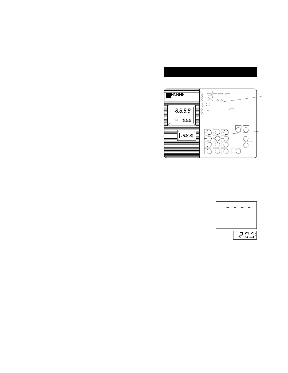
THE FRONT PANEL
CALIBRATION
ins
HI9032 microcomputer conductivity meter
LO BAT
SAMPLE
1
HOLD
CONDUCTIVITY
FERTILIZER NaCl
CON
CAL
TEMP.
2
rum n
TDS
F1
BUF
F2
HI
LO
Select
Cond. Fert. NaCl T.D.S.
1
Depress
CAL
s
e
2
Depress
3 0
Depress
ENTER
4
(refer to instruction manual for details)
When on L.C.D. is blinking, place electrode in reference buffer
5
BUF
When displayed on L.C.D. & ~ on L.C.D. is blinking, equipment confirm that
6
BUF
bufferis within ±15% of theoritical set value, but reading is still not stable yet
m
µ
S
When
7
ppm
%
gm
°C
%TC
BUF
accepting the calibration
Equipment return to OPERATION mode for measurement
8
Display
Main
Sub.
Display
Temp. Display
Cond.
7
T.D.S.
4
FTR
1
ATC
MTC
0
or
to enter calibration parameter
....
9
repeat
& when necessary
3
4
& " CON" displayed on L.C.D., depress
: The Result of measurement
: Conditions of the measurement
: Temperature reading
(Keyboard entry is shown by the blinking of Decimal point)
NaCl
Fert.
9
8
65
°C
3°F2
PGM
%TC
Clear
.
key to confirm for
CON
ON
ENTER
1. Large display for Conductivity, Fertil-
izer, NaCl and TDS
This large LCD displays the conductivity,
fertilizer, NaCl and TDS reading. The
corresponding symbol will be displayed
along with the measured value.
A "----" signal will appear on this display
to indicate an out of
range condition.
2. Temperature display
This LCD displays the temperature mea-
sured by the HI7669/2W probe or the
value that was manually set through the
keyboard. Temperature can be selected
between the Celsius and the Fahrenheit
scale by pressing the °C or the °F key
respectively.
If the probe is not connected when the meter
is turned on, the "25°C" (or "77°F") symbol
with a blinking decimal point will default.
3
OFF
4
CAL
CON
54
Page 4
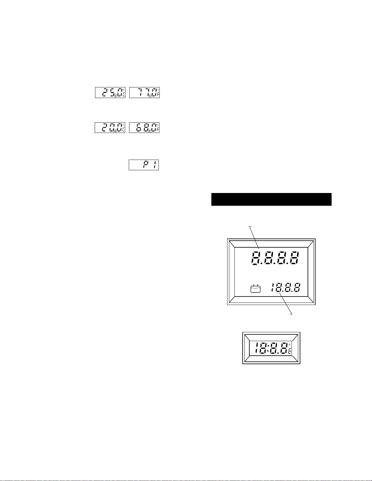
If the temperature
probe is disconnected during operation, the decimal point
will start blinking.
It will blink also if
the temperature
range is exceeded.
This LCD also displays the program # during
programming.
3. Calibration Procedure
Briefly describes calibration
procedure
4. Keyboard
• Cond key, to select conductivity mea-
surement mode
• Fert. key, to select fertilizer measure-
ment mode and to select Fertilizer #1
or #2 ("F1" or "F2")
• NaCl key, to select NaCl measure-
ment mode
• T.D.S. key, to select total dissolved
solids measurement mode
• FTR key, to select the TDS factor for
TDS measurements (see page 45)
•°C key, to display temperature in the
Celsius scale
•°F key, to display temperature in the
Fahrenheit scale
• ON key, to switch the instrument on
• OFF key, to switch the instrument off
• CAL key, to enter or exit the calibra-
tion mode
• CON key, to confirm calibration data
• ENTER Key, to confirm/enter the nu-
meric data entry
• 0 to 9 keys, numeric and decimal keys
for numeric data input
• Clear Key, to clear the numeric data
entry
LIQUID CRYSTAL DISPLAYS
Large display for Conductivity, Fertilizer, NaCl
and TDS
Primary Display
LO BAT
SAMPLE
HOLD
CONDUCTIVITY
FERTILIZER NaCl
CON
CAL
Secondary Display
BUF
TDS
F1
F2
m
µ
ppm
gm
°C
%TC
S
%
• ATM/MTC key, to select automatic or
manual temperature compensation
• %T.C. key, to select the temperature
coefficient for conductivity measurements
or to select a different conductivity buffer
during calibration (see page 21)
• PGM key, used in programming
HI
LO
TEMP. display for temperature in °C or °F
and program #
76
Page 5
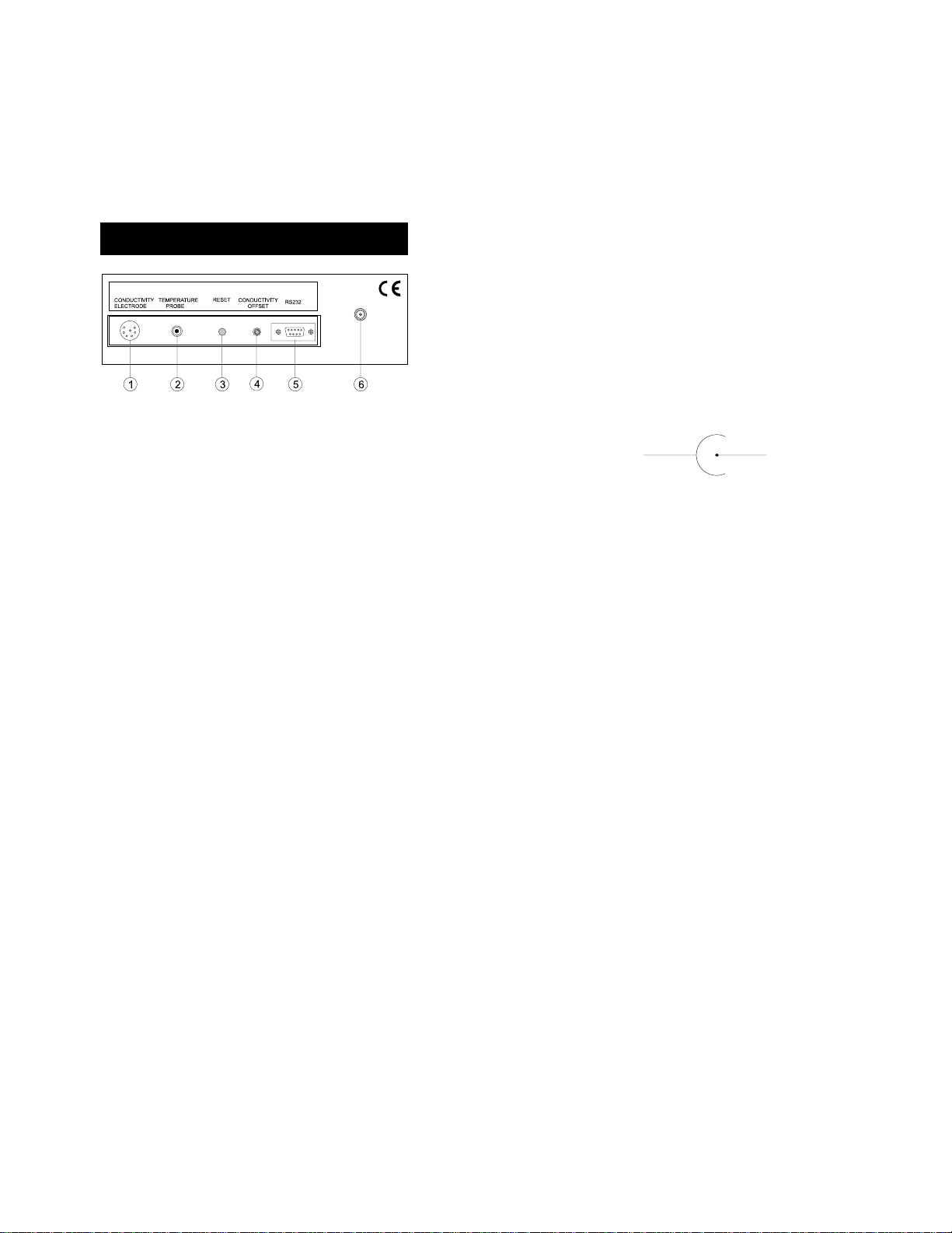
THE REAR PANEL
1. DIN female socket for the conductivity probe
(HI7686)
2. Temperature probe socket for use with the
HI7669/2W
3. Reset button
4. Potentiometer for conductivity calibration
(0.0µS)
5. RS 232C socket for serial communication.
6. DC Power Socket (for HI710005 or
HI710006).
Probes connection
Connect the supplied conductivity probe
HI7686 securely to the DIN socket provided (#1) by aligning the pins with the socket,
pushing the plug in and tightening the threaded
ring.
For temperature measurements and auto-
matic temperature compensation connect the
temperature probe HI7669/2W to the °C
socket (#2).
RESET button and restart the entire operation.
Power connection
Plug the 12VDC adapter (HI710005 or
HI710006) into the DC socket (#6).
Plug the adapter into the mains.
Note: The instrument uses the following con-
figuration.
+
It is recommendable to use Hanna HI710005
or HI710006 voltage adapters (supplied with
the meters) that use the proper polarity configuration.
HI9032 can also be used with other adapters. In this case, remember to check the
correct polarity of your adapter before connecting it to the meter.
Note:
• Make sure the main line is protected
by a fuse.
• If you need to unplug the instrument,
press the OFF key before disconnecting the meter from the mains.
-
RESET button
The RESET button (#3) is used when the
instrument displays erroneous messages due
to strong electrical interference or when the
instrument's power supply was disconnected
before the meter was switched off. Press the
98
Page 6
MEASURE
COND.
FERTILIZER
NaCl
TDS
TEMP.
RESOLUTION
COND.
FERTILIZER
NaCl
TDS
TEMP.
ACCURACY
(@20°C/68°F)
TEMP.
SPECIFICATIONS
0.0-399.9 / 399-3999 µS/cm
3.99-39.99 / 39.9-99.9 mS/cm
0.00 to 39.99 g/l
0.0 to 130.0%
0.0-199.9 / 0-1999 ppm;
0.00 to 19.99 g/l
0.0 to 50.0°C / 32.0 to 122.0°F
0.1 µS/cm; 1 µS/cm;
0.01 mS/cm; 0.1 mS/cm
0.01 g/l
0.1 pmm; 1 ppm; 0.01 g/l
0.1°C / 0.1°F
±1% full scale each range
±0.5°C / ±1°F
excluding probe error
0.1%
OPERATIONAL GUIDE
Make sure that the instrument has been calibrated before taking measurements (see calibration procedures on page 21 for conductivity, page 31 for NaCl and 35 for fertilizer).
Connect the conductivity probe to the
meter securely by aligning the pins
with the socket on the back of the
meter, pushing the plug in and tightening the threaded ring.
Connect the temperature probe to the
back of the meter for automatic temperature compensation or for temperature measurements.
If possible, to minimize any EMC interferences, use plastic beakers for
the solutions.
TYPICAL EMC
DEVIATION
CALIBRATION
TEMPERATURE
COMPENSATION
TDS FACTOR
ENVIRONMENT
DIMENSIONS
SHIPPING WEIGHT
±1% full scale all 4 ranges
±0.1°C / ±0.2°F
Automatic single point at 84µS,
1413 µS, 12.88 mS and 80.0
mS
Automatic or manual from
0 to 50°C (32 to 122°F) with
an adjustable ß from 0.0 to
3.0% per degree °C.
Adjustable from 0.01 to 0.99
0 to 50°C (32 to 122°F);
max. RH 95%
230 x 170 x 70mm
(9.1 x 6.7 x 2.7")
1.5 kg (3.3 lbs)
TAKING CONDUCTIVITY, FERTILIZER, NaCl,
TDS MEASUREMENTS
With Automatic Temperature Compensation
• Immerse the conductivity probe into the
solution submerging the
holes of the sleeve in the
sample.
Agitate the probe lightly in
the solution to remove any
air bubbles which may
have been trapped inside
the sleeve.
Immerse the temperature
probe as close as possible to the conductivity
probe.
1110
Page 7
%TC
.
ON
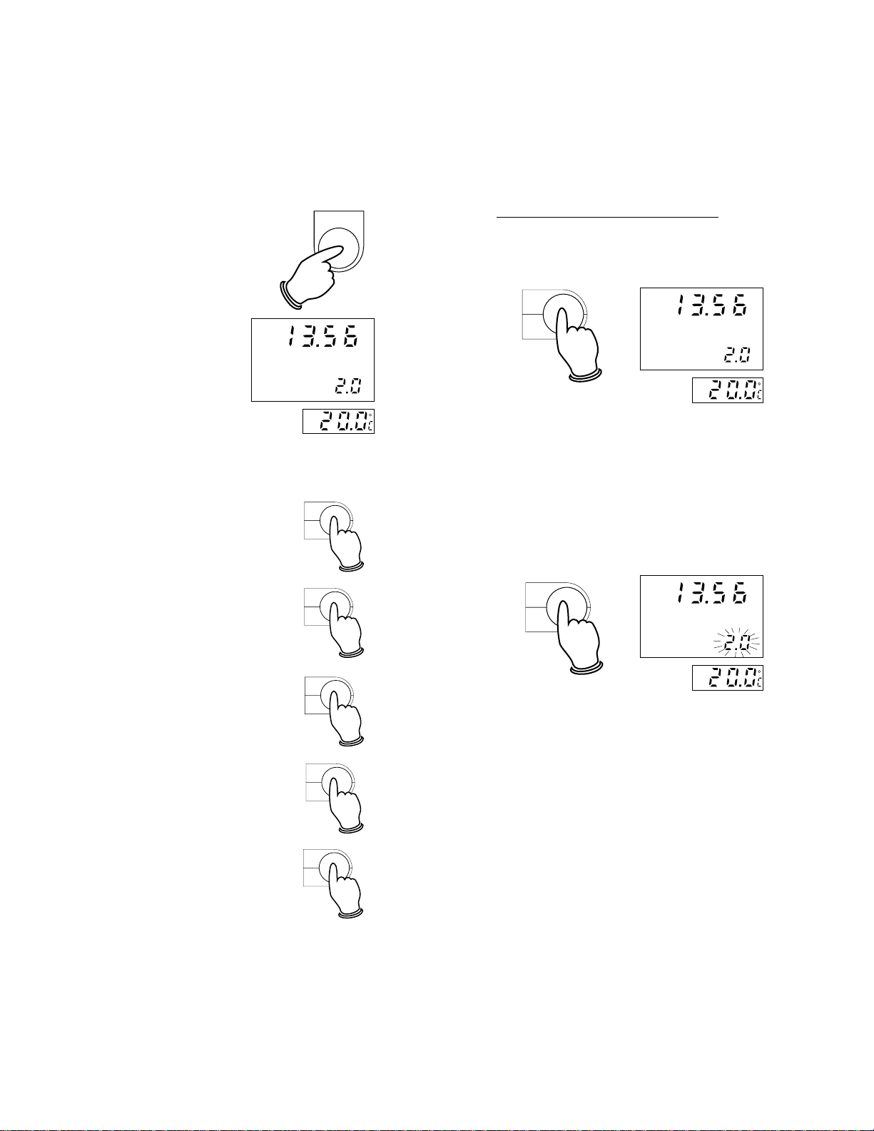
• Switch the instrument on
by pressing the ON key.
The meter automatically defaults to the
conductivity mea-
CONDUCTIVITY
m
surement mode with
2.0% as temperature
coefficient (on the
%TC
large LCD) and the
temperature in the
Celsius scale (on the TEMP. LCD).
• Select a different measurement mode by
pressing the following keys:
Fert.
• the Fert. key for fertilizer
#1
• the Fert. key twice for fer-
tilizer #2
8
Fert.
8
Conductivity measurement mode
• By pressing the Cond. key, the display
will show "CONDUCTIVITY" to confirm the
measurement mode.
m
Cond.
S
7
CONDUCTIVITY
S
%TC
• The meter will automatically default the
temperature coefficient % value to 2.0%
(shown on the secondary display) every
time it is turned on.
• Change the temperature coefficient to the
value of the solution, by pressing the %TC
key. The % value will start blinking on the
secondary LCD.
m
S
CONDUCTIVITY
%TC
• the NaCl key for NaCl of
sea water saturation.
• the T.D.S. key for total
dissolved solids
• the Cond. key to enter the
conductivity measurement
mode again.
NaCl
9
T.D.S.
4
Cond.
7
Enter the desired value by pressing the
numeric keys and then press the ENTER
key to confirm the value.
The stored value will be displayed and it
will stop blinking.
E.g. If you want to enter 2.5% as temperature coefficient value, proceed as follows:
Press the %TC key
Press 2
Press .
Press 5
1312
Page 8
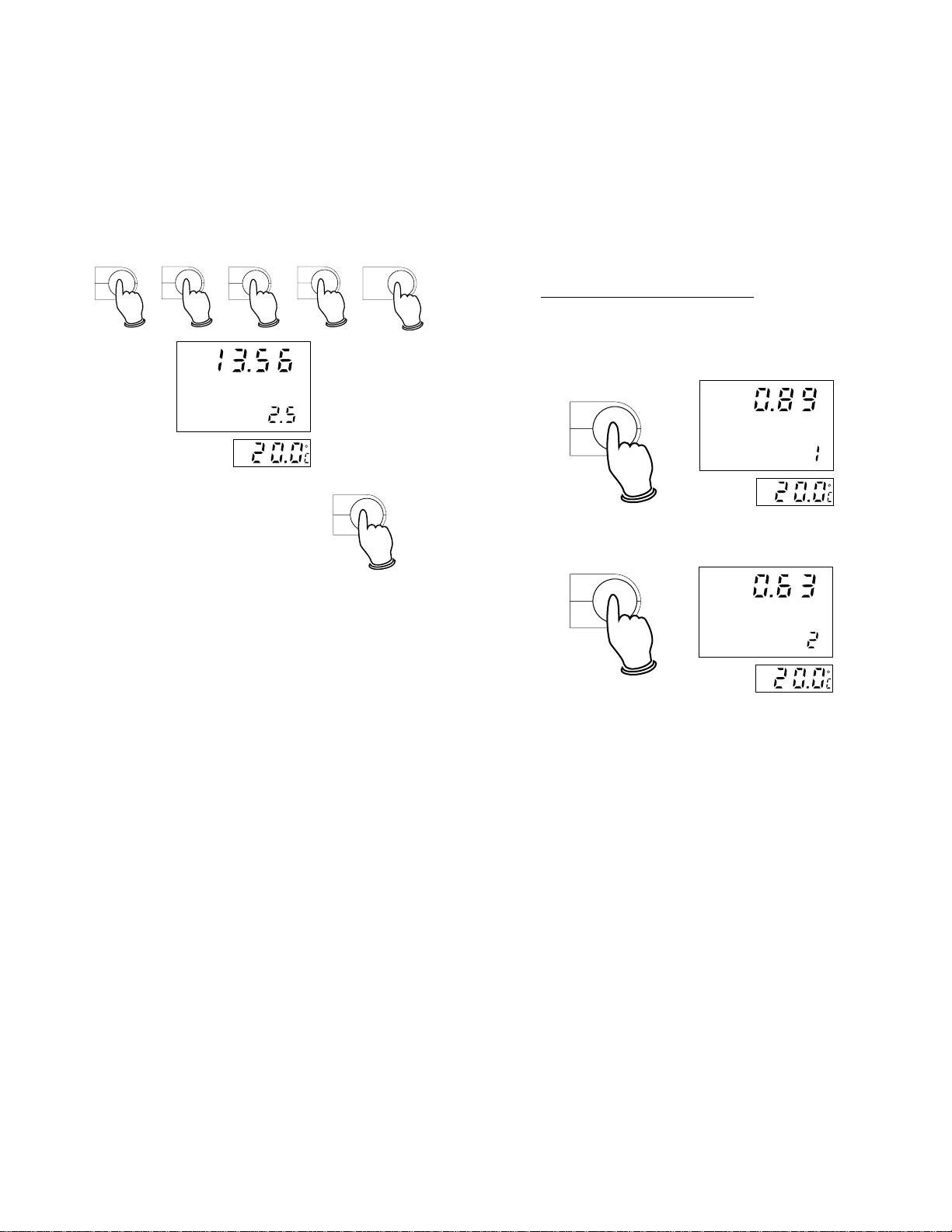
Press the ENTER key.
%TC
.
°F
2
CONDUCTIVITY
%TC
• If further measurements are desired, rinse
the probe with a small amounts of the next
sample and then proceed.
.
5
ENTER
Fertilizer measurement mode
• By pressing the Fert. key the display will
show "FERTILIZER" to confirm the mea-
m
S
surement mode and the secondary display will show "1", i.e. Fertilizer #1.
%TC
PGM
To clear the numeric entry,
Clear
press the CLEAR key.
See page 44 for the procedure to calculate the correct coefficient value.
If you need to take conductivity measurements without ATC, press the ATC/MTC key.
• HI9032 is an auto-ranging conductivity
meter and the reading automatically
switches from one resolution to the next
(from pure water @ 0.1µS/cm up to
99.9 mS/cm).
• When using HI7686 together with HI7669/
2W all readings are automatically compen-
sated for any temperature difference. Wait
for a few minutes for the temperature sensor to attain thermal equilibrium with the
test solution before taking the measurement. If the temperature of the conductivity
probe and the solution is drastically apart,
a longer time should be allowed before taking readings.
• Once the measurement reading stabilizes
the measurement is complete.
Fert.
FERTILIZER
8
gm
• Select the second fertilizer ("2") by pressing the Fert. key again.
Fert.
8
FERTILIZER
gm
• When using HI7686 together with HI 7669/
2W all readings are automatically com-
pensated for any temperature difference.
Wait for a few minutes for the temperature
sensor to attain thermal equilibrium with
the test solution before taking the measurement. If the temperature of the conductivity probe and the solution is drastically apart, a longer time should be allowed before taking readings.
• Once the measurement reading stabilizes
the measurement is complete.
• If further measurements are desired, rinse
the probe with a small amount of the next
solution and test the sample.
1514
Page 9
TDS
ppm
NaCl measurement mode
• By pressing the NaCl key the display will
show "NaCl" to confirm the measurement
mode.
NaCl
9
NaCl
%
• The meter will automatically default the
TDS factor value to 0.5 (shown on the
secondary display) every time it is turned
on.
• Change the TDS factor to the value of the
solution, by pressing the FTR key. The
TDS factor value will start blinking on the
secondary LCD.
• When using HI7686 together with HI7669/
2W all readings are automatically compen-
sated for any temperature difference. Wait
for a few minutes for the temperature sensor to attain thermal equilibrium with the
test solution before taking the measurement. If the temperature of the conductivity
probe and the solution is drastically apart,
a longer time should be allowed before taking readings.
• Once the measurement reading stabilizes
the measurement is complete.
• If further measurements are desired, rinse
the probe with a small amount of the next
solution and test the sample.
Total Dissolved Solids measurement mode
• By pressing the TDS key the display will
show "TDS" to confirm the measurement
mode.
FTR
TDS
1
ppm
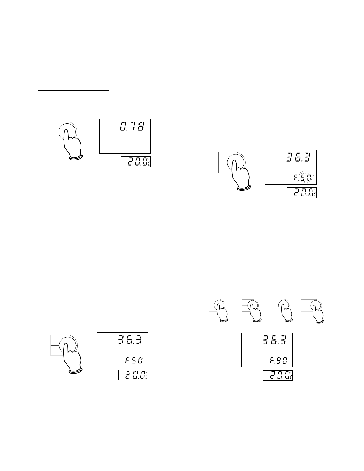
• Enter the desired value by pressing the
numeric keys and then press the ENTER
key to confirm the value.
The stored value will be displayed and it
will stop blinking.
E.g. If you want to enter 0.9 as TDS
factor, proceed as follows:
Press the FTR key
Press .
Press 9
Press the ENTER key.
FTR
1
%TC
.
NaCl
9
ENTER
T.D.S.
4
ppm
TDS
1716
Page 10
Cond.
7
• To clear the numeric entry,
PGM
press the CLEAR key.
Clear
See page 45 for further information about
the TDS factor.
• Press the ATC/MTC key and the decimal
point will blink on the TEMP. display (both
when in the Celsius and in the Fahrenheit
scale).
ATC
MTC
0
• HI9032 is an auto-ranging TDS meter,
and the reading automatically switches from
one resolution to the next (from 0.00mg/l
up to 19.99 g/l).
• When using HI7686 together with HI7669/
2W all readings are automatically compen-
sated for any temperature difference. Wait
for a few minutes for the temperature sensor to attain thermal equilibrium with the
test solution before taking the measurement. If the temperature of the conductivity
probe and the solution is drastically apart,
a longer time should be allowed before taking readings.
• Once the measurement reading stabilizes
the measurement is complete.
• If further measurements are desired, rinse
the probe with a small amount of the next
solution and test the sample.
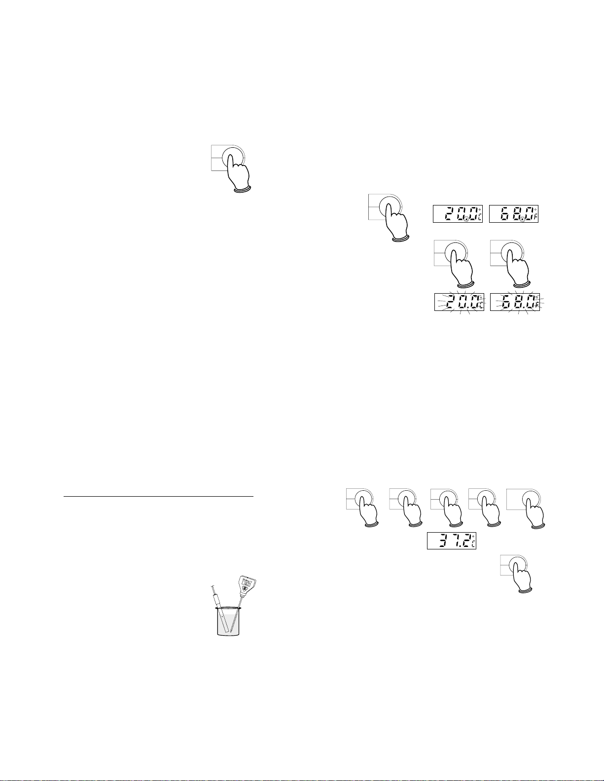
With Manual Temperature Compensation
• Immerse the HI7686 probe in the solution
submerging the holes of the sleeve into
the liquid. Tap the probe lightly on the
bottom of the recipient to remove any air
bubbles which may have being trapped
inside the sleeve.
• Take the temperature of
the solution with a
Checktemp or a glass
thermometer.
°F
2
• Press the °C or
the °F key and
°C
3
the temperature
value will start
blinking.
• Enter the temperature of the solution by
pressing the numeric keys and then press
ENTER key to confirm the value. The stored
value will be displayed and the decimal
point will stop blinking.
E.g. If you want to enter 37.2°C as temperature value, proceed as follows:
Press 3
Press 7
Press .
Press 2
Press the ENTER key and the display will
show "37.2°C".
°C
3
%TC
.
To clear the numeric entry,
press the CLEAR key.
°F
2
ENTER
PGM
Clear
• The measurement reading displayed on
the large LCD will be manually compensated for temperature variations.
1918
Page 11
• If further measurements are desired, rinse the
probe and test the next sample.
TAKING TEMPERATURE MEASUREMENTS
Taking a temperature measurement is very easy.
Connect the temperature probe
ON
to the instrument and turn the
meter on by pressing the ON key.
Dip the liquid/general purpose
temperature probe HI7669/2W
into the sample and allow the
reading on the TEMP. display
to stabilize (1 or 2 minutes).
Note: If the temperature probe is not con-
nected when the meter is turned on,
the instrument will automatically default a temperature of 25.0°C (or 77.0°F)
on the TEMP.
LCD with a
blinking decimal point.
AFTER MEASUREMENTS
When all measurements are
OFF
completed the meter should be
turned off by pressing the OFF
key and the probe cleaned.
See page 59 for the probe cleaning and maintenance procedure.
Note: The probe body and sleeve are very
susceptible to damage due to temperatures exceeding 50°C (122°F). If the
probe is exposed to high temperature,
the bond between the rings and the
probe body may become impaired and
the probe will not function properly, in
which case it has to be replaced.
CONDUCTIVITY CALIBRATION
INITIAL PREPARATION
There is a choice of 4 memorized buffers.
Choose the solution whose conductivity value
is closer to the value of the sample measured:
• 84 µS/cm @ 25°C using HI7033 (or
HI8033) conductivity solution
• 1413 µS/cm @25°C using HI7031 (or
HI8031) conductivity solution
• 12.88 mS/cm @ 25°C using HI7030 (or
HI8030) conductivity solution
• 80 mS/cm @ 25°C using HI7034 (or
HI8034) conductivity solution.
Rinse the probe thoroughly in distilled water
or if possible with a small amount of the
calibration solution. This is to minimize contamination of the calibration solution and secure higher accuracy.
When possible, use plastic beakers to minimize any EMC interferences.
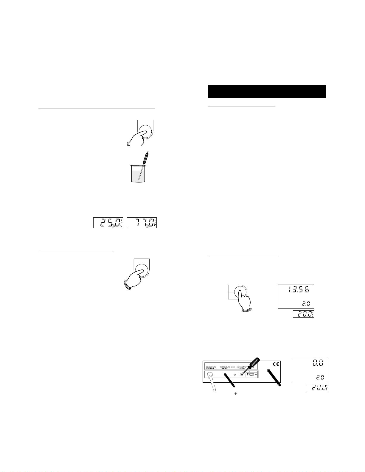
PROCEDURE WITH ATC
• Press the COND key to enter the conductivity mode, and the "CONDUCTIVITY"
symbol will appear on the large display.
m
Cond.
7
CONDUCTIVITY
S
%TC
• Leave the conductivity probe to dry in the
air.
• Using a small screwdriver adjust the OFFSET trimmer on the rear panel until the
display shows "0.0 µS".
CONDUCTIVITY
µ
S
%TC
2120
Page 12

• Press the CAL key and "12.88 mS" prompt
starts blinking with the "CAL" symbol fixed
on the display, to indicate that the buffer
value can be selected.
Once CAL is pressed, the %TC will be set
automatically to1.9%.
m
S
CAL
CONDUCTIVITY
CAL
%TC
• It is possible to operate with the four different standard buffers provided, or to
manually choose a different buffer through
the keyboard.
CALIBRATION WITH STANDARD BUFFERS
• Select a different buffer value (between
the 80 mS/cm and 12.88 mS in the mS/
cm scale or 1413 µS/cm and 84µS/cm in
the µS/cm scale) by pressing the %TC
key. The different buffer values will blink
on the primary display.
• Pour a small quantity of
the chosen conductivity solution into a beaker.
• Immerse the HI7686 probe
into the solution submerging the holes of the sleeve
into the liquid. Immerse
the HI7669/2W temperature
probe as close as possible to the conductivity
probe. Wait for 2 or 3 minutes for the thermal equilibrium.
• Press the ENTER key to
confirm the selected buffer value and the "
prompts will appear on the large display and
the " " symbol will start blinking. Wait
approximately 30 seconds for the reading
to stabilize.
ENTER
CONDUCTIVITY
BUF
CAL
m
%TC
BUF
"
S
%TC
.
%TC
m
CONDUCTIVITY
CAL
S
%TC
• When the value is
stable, " " and
"CAL" symbols will
disappear and the
"CON" symbol will
CONDUCTIVITY
CON
BUF
%TC
m
S
start blinking to
prompt the user to
µ
S
.
CONDUCTIVITY
confirm the reading.
• Press the CON key to
confirm the calibration
CON
and the instrument will
CAL
%TC
switch to normal operation.
2322
Page 13

The conductivity calibration procedure is now
complete.
Notes:
• If the buffer dif-
CONDUCTIVITY
m
fers by more than
±15% from the
set value, the "
BUF
"
BUF
CAL
%TC
symbol will blink
on the display.
Press the CAL
key to exit the
CAL
calibration mode
and repeat the
procedure using
the correct buffer.
• If the HI7669/2W temperature probe
is not connected to the meter, once
confirmed the selected buffer value,
"25°C" or "77.0°F" will start blinking on
the TEMP. display to prompt the selection of the calibration temperature
value.
• To clear the numeric data
entry, press CLEAR key.
S
• The instrument should be
PGM
Clear
calibrated weekly or every
time the probe has been
changed.
CAL
• To quit from calibration
mode, press the CAL key.
PROCEDURE WITHOUT ATC (MTC)
• If you need to calibrate without ATC,
press the ATC/MTC key. The decimal
point "." of the reading will blink on the
TEMP. display (both in the Celsius and
in the Fahrenheit scale).
ATC
MTC
0
• During calibration, once the selected
buffer value is confirmed, "25°C" or
"77.0°F" will start blinking on the TEMP.
display to prompt the selection of the
calibration temperature value.
Take the temperature of
the solution with a
Checktemp or a glass
thermometer.
Enter the correct buffer
temperature value by
using the numeric keys
ENTER
and press ENTER to
confirm the temperature
setting.
The calibration procedure is complete.
• Take the temperature of
the solution with a
Checktemp or a glass
thermometer.
• Enter the correct buffer
temperature value by
using the numeric keys
and press ENTER to
ENTER
confirm the temperature
setting.
• Continue the procedure as for calibration with ATC but without temperature
probe connection.
2524
Page 14

ATC
MTC
0
MANUAL SELECTION OF THE BUFFER
THROUGH THE KEYBOARD
If the buffer values are entered manually, the
temperature coefficient can be set to a different value than 1.9%.
• Pour a small quantity of the
chosen conductivity solution
into a plastic beaker.
• Immerse the HI7686 probe
into the solution submerging
the holes of the sleeve into
the liquid. Immerse the
HI 7669/2W temperature
probe as close as possible
to the conductivity probe.
Wait for 2 or 3 minutes for
the thermal equilibrium.
• With a standard
buffer value blinking
on the display expressed in mS, enter the desired buffer
value by pressing the
numerical keys and
CONDUCTIVITY
CAL
m
%TC
S
then press the ENTER key. The stored
value in mS will be
displayed on the primary LCD.
If the desired buffer
value is expressed
in µS, press the
%TC key first to
%TC
.
CONDUCTIVITY
CAL
µ
S
%TC
select one of the
two memorized values expressed in µS,
then enter the desired buffer value by
pressing the numerical keys followed by
the ENTER key. The stored value in µS
will be displayed on the primary LCD.
E.g. To enter 1000 µS/cm
Press %TC to
show "1413 µS"
%TC
CONDUCTIVITY
.
CAL
Press 1
Press 0
Press 0
Press 0
Press the ENTER key.
FTR
1
ATC
MTC
ATC
MTC
0
0
ENTER
• The stored value will
be displayed on the
primary LCD and the
CONDUCTIVITY
"2.0" value as %TC
will blink on the sec-
CAL
ondary LCD to
prompt the user to
enter the desired
temperature coefficient value.
• Use the numerical keys to enter the desired value and press the ENTER key.
E.g. to enter 2.5%
Press 2
Press .
Press 5
Press the ENTER key.
°F
2
%TC
.
5
ENTER
%TC
µ
S
%TC
µ
S
2726
Page 15

• The "CAL" and "
BUF
prompts will appear
on the large display
and the " " symbol will start blinking. Wait for approximately 30 seconds for the reading
to stabilize.
• When the value is
stable, " " and
"CAL" symbols will
disappear and the
"CON" symbol will
start blinking to
prompt the user to
confirm the reading.
• Press the CON key
to confirm the calibration.
"
CONDUCTIVITY
BUF
CAL
CONDUCTIVITY
CON
BUF
CON
µ
%TC
%TC
S
• If the HI7669/2W temperature probe is
not connected to the meter, once the
selected buffer value is confirmed,
"25°C" or "77.0°F" will start blinking on
the TEMP. display to prompt the selection of the calibration temperature
value.
µ
S
Take the temperature
of the solution with a
Checktemp or a glass
thermometer.
Enter the correct buffer
temperature value by
using the numeric keys
ENTER
and press ENTER to
confirm the temperature
setting.
Now the calibration procedure is complete.
• To quit the calibration mode,
CAL
press the CAL key.
The conductivity calibration procedure is now
complete.
Notes:
µ
• If the buffer value
differs by more
CONDUCTIVITY
than ±15% from
the ideal value,
BUF
the "
" symbol
BUF
CAL
%TC
will blink on the
display.
Press the CAL
key to exit the
CAL
calibration mode
and repeat the
procedure using
the correct buffer.
PGM
• To clear the numeric data
S
entry, press CLEAR key.
Clear
• The instrument should be calibrated
weekly or every time the probe has
been changed.
PROCEDURE WITHOUT ATC (MTC)
• If you need to calibrate without ATC,
press the ATC/MTC key and the decimal point will blink on the TEMP. LCD
2928
Page 16

(both in the Celsius and in the Fahrenheit scale).
• During calibration once
the selected buffer value
is confirmed, "25°C" or
"77.0°F" will start blinking on the TEMP. display to prompt the selection of the calibration
ENTER
temperature value.
• Take the temperature of
the solution with a
Checktemp or a glass thermometer.
• Enter the correct buffer temperature
value by using the numeric keys and
press ENTER to confirm the temperature setting.
• Continue the procedure as for calibration with ATC, but without temperature
probe connection.
NaCl CALIBRATION
INITIAL PREPARATION
Rinse the probe thoroughly in distilled water.
This is to minimize contamination of the calibration solution and secure higher accuracy.
Pour a small quantity of
HI7037 Standard solution into
a plastic beaker or any other
solution to be used as 100%
reference.
When possible, use plastic
beakers to minimize any EMC
interferences.
PROCEDURE WITH ATC
• Press the NaCl key to enter the sea water
percentage mode, and the "NaCl" symbol
will appear on the large display.
NaCl
9
NaCl
%
• Press CAL and the LCD will display
"100.0%".
%
CAL
NaCl
CAL
• Press the ENTER key and immerse the HI7686 probe into
ENTER
the calibration solution submerging the holes of the sleeve into
3130
Page 17

the liquid. Immerse the
HI 7669/2W temperature
probe as close as possible to the conductivity
probe. Wait for 2 or 3 minutes for the thermal equilibrium.
• If the buffer is within
39 and 49 mS, the
BUF
"
" symbol stays
still.
Notes:
• If the temperature probe is not connected to the meter, once the selected
buffer value is confirmed, "25°C" or
"77°F" will start blinking on the TEMP.
display.
%
NaCl
BUF
CAL
Enter the sample temperature value using the numeri-
ENTER
cal keys and press the ENTER key to confirm the temperature setting.
• If the " " starts
blinking, wait for approximately 30 sec-
NaCl
BUF
CAL
onds for the reading
to stabilize.
• Once the reading is
CON
NaCl
BUF
stable the " "
symbol goes off and
CON prompts the
user to confirm the
reading.
• Press the CON key to
CON
confirm the calibration.
The instrument is now calibrated and returns
to normal operation.
%
Now the calibration procedure is complete.
• To quit from the calibration
CAL
mode, press the CAL key.
• To clear the numeric data
entry, press the CLEAR key.
%
PROCEDURE WITHOUT ATC
PGM
Clear
(MTC)
• If you need to calibrate without ATC,
press the ATC/MTC key and the decimal point will blink on the TEMP. LCD
(both in the Celsius and in the Fahrenheit scale).
ATC
MTC
0
• During calibration once the selected
buffer value is confirmed, "25°C" or
"77.0°F" will start blinking on the TEMP.
display to prompt the selection of the
calibration temperature value.
3332
Page 18

• Take the temperature of
the solution with a
Checktemp or a glass
thermometer.
• Enter the correct buffer
temperature value by
using the numeric keys
ENTER
and press ENTER to
confirm the temperature
setting.
• Continue the procedure as for calibration with ATC, but without temperature
probe connection.
FERTILIZER CALIBRATION
INITIAL PREPARATION
Dissolve 1 g of the fertilizer to be used in 1 L
of distilled water.
Rinse the probe thoroughly in distilled water.
This is to minimize contamination of the calibration solution and secure higher accuracy.
When possible, use plastic beakers to minimize any EMC interferences.
Fert.
PROCEDURE WITH ATC
8
• Press the Fert key button to enter the fertilizer
#1 mode.
• Leave the conductivity probe to dry in the
air.
• Using a small screwdriver adjust the OFFSET trimmer on the rear panel until the
reading is "0.00 gm".
FERTILIZER
• Press the CAL key and "1.00 gm" will
blink on the primary LCD to prompt the
user to select the calibration buffer value.
The "CAL" symbol will also be displayed.
CAL
FERTILIZER
CAL
3534
gm
gm
Page 19

Fert.
8
• Pour a small quantity of
the prepared fertilizer solution into a plastic beaker.
• Immerse the HI7686 probe
into the solution submerging the holes of the sleeve
into the liquid. Immerse the
HI7669/2W temperature
probe as close as possible to the conductivity
probe. Wait for 2 or 3 minutes for the thermal equilibrium.
• Press the ENTER key to accept the
1.00 gm value, otherwise enter manually
the desired value through the keyboard
followed by the ENTER key to confirm the
entry of the calibration value. The "
BUF
prompt will appear on the large display
and the " " symbol will start blinking. Wait approximately 30 seconds for
the reading to stabilize.
• Once the reading is stable, " " and
ENTER
FERTILIZER
BUF
CAL
gm
to confirm the calibration
and the instrument will re-
CON
turn to normal operation.
The Fertilizer #1 calibration procedure is now complete.
HI 9032 can memorize two different measurements of Fertilizer concentration. By
pressing the Fert key, you can switch the
two measurements.
To perform 2nd Fert calibration press the
Fert key and the secondary section on the
large LCD will then show "2".
gm
"
FERTILIZER
Proceed with the operation as for the 1st Fert
calibration (see above).
Notes:
• If the HI 7669/2W temperature probe is
not connected to the meter, once confirmed the Fert concentration value,
"25°C" or "77.0°F" will start blinking on
the TEMP.display.
"CAL" will go off and
"CON" prompts to
confirm the reading.
• Press the CON key
FERTILIZER
CON
gm
Take the temperature
of the solution with a
BUF
Checktemp or a glass
thermometer.
3736
Page 20

Enter the correct sample
temperature value by us-
ENTER
ing the numerical keys
and press ENTER to confirm the temperature setting.
Now the calibration procedure is complete.
• To quit from the calibra-
CAL
tion mode, press the
CAL key.
PGM
• To clear the numeric data
entry, press the CLEAR
Clear
key.
PROCEDURE WITHOUT ATC (MTC)
• If you need to calibrate without ATC,
press the ATC/MTC key and the decimal point will blink on the TEMP. display (both in the Celsius and in the
Fahrenheit scale).
• Take the temperature of
the solution with a
Checktemp or a glass
thermometer.
• Enter the correct buffer
temperature value by
using the numeric keys
ENTER
and press ENTER to
confirm the temperature
setting.
• Continue the procedure as for calibration with ATC, but without temperature
probe connection.
ATC
MTC
0
• During calibration, once the selected
buffer value is confirmed, "25°C" or
"77.0°F" will start blinking on the TEMP.
display to prompt the selection of the
calibration temperature value.
3938
Page 21

SETTING TEMPERATURE
• Press ENTER ("37.2 °C will be displayed
on the LCD).
To set a temperature value manually, proceed
as follows:
• Disconnect the temperature probe or press
ATC/MTC. The decimal point will blink on
the TEMP. display (both in the Celsius
and in the Fahrenheit scale).
ATC
MTC
0
• Press the °C or the °F key to select the
scale.
°C
3
• Press the °C or °F key to enter the setting
mode and the temperature value will start
blinking.
°C
3
Cond.
7
%TC
.
Note: To clear the numeric
entry, press the
CLEAR key.
°F
2
ENTER
PGM
Clear
°C
3
e.g. to enter 37.2 °C
• Press 3
• Press 7
• Press .
• Press 2
4140
Page 22

SETTING TEMPERATURE COEFFICIENT
To set a temperature coefficient value manually, proceed as follows (only available in
conductivity measurement mode):
e.g. to enter 2.5 %TC
• Press %TC ("%TC" will blink on LCD)
m
%TC
CONDUCTIVITY
.
S
%TC
• Press 2
• Press .
• Press 5
• Press ENTER ("2.5 %TC will fix on LCD).
°F
2
%TC
.
CONDUCTIVITY
%TC
ENTER
m
S
5
Both parameters are temperature dependent.
The dependency of conductivity on temperature is expressed as a relative change per
degree Celsius at a particular temperature,
commonly as percent °C.
The following table reports the conductivity
values at various temperatures.
°C °F HI7030 HI7031 HI 7033 HI7034 HI7035 HI7039
HI8030 HI8031 HI8033 HI8034 HI8035 HI8039
(µS/cm) (µS/cm) (µS/cm) (µS/cm) (µS/cm) (µS/cm)
0 32.0 7150 776 64 48300 65400 2760
5 41.0 8220 896 65 53500 74100 3180
10 50.0 9330 1020 67 59600 83200 3615
15 59.0 10480 1147 6 8 65400 92500 4063
16 60.8 10720 1173 7 0 67200 94400 4155
17 62.6 10950 1199 7 1 68500 96300 4245
18 64.4 11190 1225 7 3 69800 98200 4337
19 66.2 11430 1251 7 4 71300 100200 4429
20 68.0 11670 1278 7 6 72400 102100 4523
21 69.8 11910 1305 7 8 74000 104000 4517
22 71.6 12150 1332 7 9 75200 105900 4711
23 73.4 12390 1359 8 1 76500 107900 4805
24 75.2 12640 1386 8 2 78300 109800 4902
25 77.0 12880 1413 8 4 80000 111800 5000
26 78.8 13130 1440 8 6 81300 113800 5096
27 80.6 13370 1467 8 7 83000 115700 5190
28 82.4 13620 1494 8 9 84900 117700 5286
29 84.2 13870 1521 9 0 86300 119700 5383
30 86.0 14120 1548 9 2 88200 121800 5479
31 87.8 14370 1575 9 4 90000 123900 5575
The conductivity of an aqueous solution is
the measure of its ability to carry an electrical current by means of ionic motion.
The conductivity invariably increases with increasing temperature.
It is affected by the type and number of ions
in the solution and by the viscosity of the
solution itself.
Acids, alkalis and concentrated salt solutions have lower values, typically 1.5%/°C.
Since a small difference in temperature causes
a large change in conductivity readings the
readings are usually normalized at 25°C.
HI 9032 automatically compensates for temperature differences when used with the temperature probe provided.
4342
Page 23

ENTER
m
The temperature coefficient automatically defaults to 2% when the
CONDUCTIVITY
S
meter is turned on and
can be set from 0%
%TC
(without compensation)
to 3% per degree Celsius.
DETERMINATION OF THE TEMPERATURE
COEFFICIENT OF A SOLUTION
Follow the procedure described
below:
SETTING TDS FACTOR
To set a TDS factor value proceed as follows
(only available in TDS measurement mode):
e.g. 0.90
• Press the FTR key
FTR
TDS
1
ppm
• Immerse the probe into a sample
of the solution.
• Set the temperature coefficient to 0% (i.e.
no compensation) as follows:
Press the %TC key
Press 0
Press the ENTER key.
%TC
.
ATC
MTC
0
ENTER
CONDUCTIVITY
• Condition the sample and probes at 25°C and
write down the conductivity reading "C25".
• Condition the sample and probes to a
temperature t°C which is approximately
5°C to 10°C different from 25°C and note
the conductivity reading "Ct".
• The temperature coefficient ß of the solution is calculated with the formula:
(Ct - C25)
ß = 100 x ---------------------------
(t - 25) x C25
m
%TC
• Press .
• Press 9
• Press ENTER ("F 0.90" will fix on LCD)
%TC
.
S
NaCl
ppm
9
TDS
The TSD value in aqueous solutions is directly proportional to the conductivity of a
solution.
The ratio between the two measures depends on the solution and usually it is set to
a factor of 0.5 (CaCo
). This means that
3
each µS/cm is converted in 0.5 mg/l or
0.5 ppm.
With HI 9032 the TDS factor can be set to
the most appropriate value depending on the
solution to be measured.
For accurate TDS measurements with HI9032
make sure the meter has been calibrated in
conductivity and the temperature coefficient
is properly set.
4544
Page 24

The following table reports the TDS calibration
solution values at various temperatures.
PROGRAMS
°C °F HI7032 HI7036 HI7038
pp m ppt ppt
(mg/L) (g/L) (g/L)
0 32.0 758 3.58
5 41.0 676 4.11
10 50.0 999 8.99 4.67
15 59.0 1122 10.10 5.24
16 60.8 1148 5.36
17 62.6 1173 5.48
18 64.4 1200 5.60
19 66.2 1224 5.72
20 68.0 1251 11.24 5.84
21 69.8 1277 5.96
22 71.6 1303 6.08
23 73.4 1329 6.20
24 75.2 1358 6.32
25 77.0 1382 12.41 6.44
26 78.8 1408 6.57
27 80.6 1438 6.69
28 82.4 1461 6.81
29 84.2 1476 6.94
30 86.0 1515 13.61 7.06
31 87.8 1541 7.19
There are 7 programs stored in the memory
of the instrument altogether. To select a particular program, press the PGM key, followed
by the program number on the keyboard,
and the ENTER key.
The 7 programs stored in the instrument are:
Program 1 : Setting of RS232 Baud Rate
Program 2 : Setting of RS232 ESC code
Program 3 : Reset of the Baud Rate &
ESC code to default value
Program 7 : To display or set the con-
ductivity calibration factor
Program 8 : To display or set Fert 1/2
calibration factor
Program 9 : To display or set NaCl cali-
bration factor
Program 0 : To exit
To select any program press PGM first and
"P 0" will be blinking on the primary display.
PGM
Clear
Press the number key of the desired program on the keyboard (x). "Px" will blink on
the primary display. Press the ENTER key
and "Px" will appear on the small display.
e.g. To select Program 1:
• Press PGM and
"P0" will blink on
PGM
Clear
the large LCD
4746
Page 25

• Press 1 and "P1"
will blink
• Press ENTER
FTR
1
ENTER
and "P 1" will be
displayed on the
TEMP. LCD
To stop any of the programs or to quit to
revert to normal operation:
• Press the PGM key
• Press 0
• Press the ENTER key.
PGM
Clear
ATC
MTC
0
ENTER
PROGRAM # 2
Setting of RS232 ESC code
e.g. ESC code is 20 (decimal)
• Press PGM
• Press 2
• Press ENTER. "P 2" on the TEMP. display
and the current setting will blink on the
primary LCD
• Press 2
• Press 0. "20" will blink on the primary LCD
• Press ENTER. "20" will be fixed on the primary
LCD
To return to normal operation:
• Press the PGM key
• Press 0
• Press the ENTER key.
PROGRAM # 1
Setting of RS232 Baud Rate
e.g. Baud Rate 300
• Press PGM
• Press 1
• Press ENTER. "P 1" on the TEMP. dis-
play and the current setting will blink on
the primary LCD
• Press 3
• Press 0
• Press 0. "300" will blink on the primary LCD
• Press ENTER . "300" will be fixed on the pri-
mary LCD
To return to normal operation:
• Press the PGM key
• Press 0
• Press the ENTER key.
PROGRAM # 3
Resetting RS232 code and Baud Rate to the
default value
• Press PGM
• Press 3
• Press ENTER. "P 0" will blink on the
primary LCD
To return to normal operation press the ENTER key.
PROGRAM # 7
To display or set conductivity calibration factor
A. To display the conductivity calibration factor
• Press PGM
• Press 7
• Press ENTER. "P 7" and the current con-
ductivity calibration factor will appear respectively on the TEMP. and on the primary LCD
4948
Page 26

B. Setting the conductivity calibration factor
e.g. CAL factor is 0.999
• Press the CAL key and the current calibration factor will blink on the primary LCD
• Press .
• Press 9
• Press 9
• Press 9. "0.999" and "CAL" symbol will
blink on the large LCD
• Press ENTER. "0.999" will be fixed on
large LCD with the "CON" symbol will be
blinking
• Press the CON key
Note: To quit from the setting mode, press
the CAL key.
This program provides a fast way to perform
the calibration (without going through the calibration procedure) based on the formula:
KCond = (CALBUF * (1 + TC (TP - 25 )) / Gt
where:
CALBUF = calibrated buffer solution
Gt = measured solution conductivity at Tp
TC = temperature coefficient
TP = sample temperature in °C
e.g. The buffer value is 1000 µS/cm, but the
meter shows 900 µS/cm, so by changing the KCond to 1.111, the meter will
then show 1000 µS/cm and the meter
is calibrated.
* calibration factor value range: 0.850 - 1.150
To return to normal operation:
• Press the PGM key
• Press 0
• Press the ENTER key.
PROGRAM # 8
To display or set Fert 1/2 calibration factor
A. To display the Fert 2 calibration factor
• Press PGM
• Press 8
• Press ENTER. "P 8" and the current fertil-
izer calibration factor will respectively appear on the TEMP. and on the primary
LCD. The secondary display will show "2"
for Fertilizer #2
B. To change the fertilizer #:
• Press the PGM key again
• Press 8 again
• Press the ENTER key. "P 8" and the
current fertilizer calibration factor will respectively appear on the TEMP. and on
the primary LCD. The secondary display
will show "1" for Fertilizer #1
C. To set the Fert 1 calibration factor:
e.g. CAL factor 0.999
• Press CAL and the current setting will
blink on the primary LCD
• Press .
• Press 9
• Press 9
• Press 9 and "0.999" will blink on the pri-
mary LCD
• Press the ENTER key. "0.999" stays still
and the "CON" symbol will blink
• Press the CON key to confirm and the
"CON" symbol will disappear
Note: To quit from the setting mode, press
the CAL key.
5150
Page 27

This program provides a fast way to perform
the calibration (without going through the "CAL"
procedure) based on the formula:
KFERT = (CALBUF * (1 + 3.0% (Tp-25)) / Gt
where:
CALBUF = calibrated buffer solution
Gt = measured solution conductivity at Tp
Tp = temperature in °C
e.g. The buffer value is 1.00 g, but the
meter shows 0.9 g, so by changing the
KFert to 1.111, the meter will then
show 1.00 g and the meter is calibrated.
• Press .
• Press 9
• Press 9
• Press 9. "0.999" will blink on the primary
LCD with the "CAL" symbol blinking
• Press the ENTER key. "0.999" stays still
and the "CON" symbol starts blinking
• Press the CON key to confirm and the
"CON" symbol will disappear
Note: To quit from the setting mode, press
the CAL key.
* calibrated factor value range : 0.01 - 1.50
To return to normal operation:
• Press the PGM key
• Press 0
• Press the ENTER key.
PROGRAM # 9
To set or display the NaCl calibration factor
A. To display the NaCl calibration factor:
• Press PGM
• Press 9
• Press ENTER and "P 9" and the current
NaCl calibration factor will respectively
appear on the TEMP. and on the primary
LCD
B. To set the NaCl calibration factor:
e.g. CAL factor 0.999
• Press the CAL key and the current calibra-
tion factor will blink on the primary display.
This program provides a fast way to perform
the calibration (without going through the "CAL"
procedure) based on the formula:
KNaCl = (CALBUF * (1 + 1.95% (Tp-25)) / Gt
CALBUF= calibrated buffer solution
Gt = measured solution conductivity at TP
Tp = temperature in °C
e.g. The buffer value is 100.0%, but the
meter shows 90.0%, so by changing
the KNaCl to 1.111, the meter will show
100.0% and will be completely calibrated.
* calibrated factor value range : 0.5 - 3.5
To revert to normal operation:
• Press the PGM key
• Press 0
• Press the ENTER key.
5352
Page 28

INTERFACE WITH PC
Data transmission from the instrument to
the PC is now much easier with the new
HI 92000 Windows® compatible application
software offered by Hanna Instruments.
User friendly, HI 92000 offers a variety of
features and has an on line help feature to
support you throughout all situations.
HI 92000 allows you to use the powerful
means of the most diffused spread sheet
programs (e.g. Excel©, Lotus 1-2-3©). Simply run your favorite spread sheet and
open the file downloaded by HI 92000. It is
then possible to make any elaboration available with your software (e.g. graphics, statistical analysis).
To install HI 92000 you need a 3.5" drive
and few minutes to follow the instructions
conveniently printed on the disk's label.
IContact your Hanna Dealer to request a
copy.
To connect your HI 9032 to the PC use
HI 920010, available through your Hanna
Dealer. Make sure that your meter is
switched off and plug the connectors, one
into the meter RS232C connector, the other
into the serial port of your PC.
Note: Cables different from the HI 920010
may use a different configuration. In
such case any communication between the meter and the PC is not
possible.
If you are not using Hanna Instruments
HI 92000 application software, please find
here below some additional information to
help your connection to the PC.
SETTING THE BAUD RATE AND THE COMMAND PREFIX
See program # 1.
CHANGING THE COMMAND PREFIX
Sometimes it is necessary to change the
command prefix. If your computer already
uses the DLE character for control purposes, sending it to the conductivity meter
can be difficult or cause your computer to
behave erratically.
To avoid this problem, you can change the
command prefix to almost every ASCII character (0 - 127 decimal).
To change the command prefix, refer to
PGM 2 operation.
The carriage return is the only character
that cannot be used as a command prefix.
Good choices for command prefix are ESC
(ASCII code 27), SO (ASCII code 15), or
any printing character you will not use for
other purposes; e.g. the C symbol (ASCII
code 64).
SENDING COMMANDS FROM PC
With terminal programs such as, for example, Telix®, Windows Terminal®,
HyperTerminal®, it is possible to remotely
control your HI 9032. Use HI 920010 cable
to connect the meter to the PC, start the
terminal program and set the communication options as follows: 8, N, 1, no flow
control.
Excel© Copyright of "Microsoft Co."
Lotus 1-2-3© Copyright of "Lotus Co."
Windows® is registered Trademark of "Microsoft Co."
5554
Page 29

Command Types
To send a command to the pH meter the
scheme is: <DLE> <
command>
<CR>
This line makes the computer send a Data
Link Escape character, the command expressed as a number or a 3-character sequence) and a CR character.
Note: Windows Terminal® and all the other
terminal programs that support the
ANSI escape sequence, represent
the DLE character by the string '^P'
and the CR character by the string
'^M'. E.g. the line '^PPHR^M' sets
the range to pH.
Commands not requiring an answer from
the pH meter
CONMselects conductivity measurement
TDSM selects TDS measurement
NaM selects NaCl measurement
Ft1M selects Fert 1st buffer measurement
Ft2M selects Fert 2nd buffer measurement
CAL same as pressing the CAL key
CON same as pressing the CON key
ENT same as pressing the ENTER key
PGM same as pressing the PGM key
CLR same as pressing the Clear key
TPC same as pressing the C key
TPF same as the F key
TCK same as the %TC key
TKF same as the Factor key
Commands requiring an answer
CON? causes the meter to send the
conduc- tivity value through the
serial interface. If the reading is
out of range, ERR1 is sent instead of the conductivity value.
TDS? causes the meter to send the TDS
value through the serial interface.
If the reading is out of range, ERR`
is sent instead of the TDS value.
Na? causes the meter to send the NaCl
value through the serial interface.
If the reading is out of range,
ERR1 is sent instead of the NaCl
value.
Ft1? causes the meter to send the Fert
1st value through the serial interface. If the reading is out of range,
ERR1 is sent instead of the Fert
value.
Ft2? causes the meter to send the Fert
2nd value through the serial interface. If the reading is out of range,
ERR1 is sent instead of the Fert
value.
TPC? causes the meter to send the °C
temperature value through the serial interface. If the reading is out
of range, ERR1 is sent instead of
the temperature value.
TC? causes the meter to send the tem-
perature coefficient value.
TF? causes the meter to send the TDS
Factor value.
KC? causes the meter to send the con-
ductivity calibration coefficient
value.
KT? causes the meter to send the TDS
calibration factor value.
KF1? causes the meter to send the
Fertilizer 1st buffer calibration factor value.
KF2? causes the meter to send the Fer-
tilizer 2nd buffer calibration factor
value.
KN? causes the meter to send the NaCl
calibration factor value.
5756
Page 30

Numeric Entries
0, 1, 2, 3, 4, 5, 6, 7, 8, 9, and . - same as
pressing the numeric key on the keyboard.
The maximum length of a numeric entry is
7 characters (plus DCE and the CR).
CHANGING THE COMMAND PREFIX
These commands may be sent with either
capital or small letters. Invalid commands
will be ignored. The characters sent by
HI 9032 are always capital letters.
SPECIFICATIONS
• Serial interface compatible with RS232 lev-
els.
• Optically insulated.
• 8 - bit data trasmitted, one start bit, one
stop bit, no parity.
• 8 - bit data received, no parity checking,
one start and one stop bit.
• Baud rate selectable: 150 - 2400 baud.
PROBE MAINTENANCE
Rinse the probe with
tap water after every
series of measurements. If a more thorough cleaning is required, remove the
glass sleeve and clean
the probe with a cloth
or a nonabrasive detergent.
After cleaning the
probe, re-calibrate the
instrument.
The four ring platinum
probe body and sleeve
are in glass. For this
reason great care
while handling the
probe must be payed.
5958
Page 31

ACCESSORIES
CONDUCTIVITY & TDS BUFFER SOLUTIONS
HI 7030L 12880 µS/cm (µmho/cm), 460 mL
HI 7030M 12880 µS/cm (µmho/cm), 230mL
HI 7031L 1413 µS/cm (µmho/cm), 460mL
HI 7031M 1413 µS/cm (µmho/cm), 230mL
HI 7033L 84 µS/cm (µmho/cm), 460 mL
HI 7033M 84 µS/cm (µmho/cm), 230 mL
HI 7034L 80000 µS/cm (µmho/cm), 460mL
HI 7034M 80000 µS/cm (µmho/cm), 230mL
HI 7035L 111800 µS/cm (µmho/cm), 460 mL
HI 7035M 111800 µS/cm (µmho/cm), 230 mL
HI 7039L 5000 µS/cm (µmho/cm), 460mL
HI 7039M 5000 µS/cm (µmho/cm), 230mL
HI 7032L 1382 ppm (mg/l), 460 mL
HI 7032M 1382 ppm (mg/l), 230 mL
HI 7036L 12.41 ppt (g/l), 460 mL
HI 7036M 12.41 ppt (g/l), 230 mL
HI 7038P 6.44 ppt (g/l), 2 x 30 mL
PROBES
HI 7686 Platinum conductivity probe
useing the 4-ring method. The
probe screened cable is 1m
(3.3') long.
HI7669/2W Temperature probe
OTHER ACCESSORIES
CHECKTEMPC Electronic thermometer
(range: -50.0 to 150.0°C)
CHECKTEMPF Electronic thermometer
(range: -58.0 to 302°F)
HI710005 115VAC-12VDC converter
HI710006 230VAC-12VDC converter
CONDUCTIVITY & TDS BUFFER SOLUTIONS IN FDA APPROVED BOTTLES
HI 8030L 12880 µS/cm (µmho/cm), 460 mL
HI 8031L 1413 µS/cm (µmho/cm), 460 mL
HI 8033L 84 µS/cm (µmho/cm), 460 mL
HI 8034L 80000 µS/cm (µmho/cm), 460 mL
HI 8035L 111800 µS/cm (µmho/cm), 460mL
HI 8039L 5000 µS/cm (µmho/cm), 460 mL
SALINITY (SODIUM CHLORIDE) SOLUTIONS
HI 7037L Standard Sea Water, 460 mL
HI 7037M Standard Sea Water, 230 mL
HI76405 Probes holder
HI 92000/16 Windows® 3.11 compatible ap-
plication software
HI 92000/32 Windows® 95 compatible ap-
plication software
HI 920010 PC connection cable (25-pin)
HI 920010/9 PC connection cable (9-pin)
MAN9032R2 Instruction Manual
6160
Page 32

WARRANTY
All Hanna Instruments meters are warranted
for two years against defects in workman-
ship and materials when used for their intended purpose and maintained according to
the instructions.
The probes are warranted for a period of
six months.
CE DECLARATION OF CONFORMITY
DECLARATION OF CONFORMITY
Damages due to accidents, misuse, tampering or lack of prescribed maintenance are
not covered. This warranty is limited to repair
or replacement free of charge.
If service is required, contact the dealer from
whom you purchased the instrument. If under warranty, report the model number, date
of purchase, serial number and the nature of
the failure. If the repair is not covered by the
warranty, you will be notified of the charge
for repair or replacement. If the instrument is
to be returned to Hanna Instruments, obtain
a Return Goods Authorization from the Customer Service Department first and then send
it with shipment costs prepaid. When shipping any instrument, make sure it is properly
packaged for complete protection.
To validate your warranty, fill out and return
the enclosed warranty card within 14 days
from the date of purchase.
All rights are reserved. Reproduction in whole
or in part is prohibited without the written
consent of the copyright owner.
Hanna Instruments reserves the right to
modify the design, construction and appearance of its products without advance
notice.
We
Hanna Instruments Srl
V.le delle industrie 12
35010 Ronchi di Villafranca (PD)
ITALY
herewith certify that the bench conductivity meter
has been tested and found to be in compliance with the following regulations:
IEC 801-2 Electrostatic Discharge
IEC 801-3 RF Radiated
IEC 801-4 Fast Transient
EN 55022 Radiated, Class B
Date of Issue: 04-01-1996
Recommendations for Users
Before using this product, make sure that it is entirely suitable for the environment
in which it is used.
Operation of this instrument in residential area could cause unacceptable interferences to radio and TV equipments, requiring the operator to take all necessary steps
to correct interferences.
The metal band at the end of the probe is sensitive to electrostatic discharges. Avoid
touching this metal band at all times.
During operation, ESD wrist straps should be worn to avoid possible damage to the
electrode by electrostatic discharges.
Any variation introduced by the user to the supplied equipment may degrade the
instrument's EMC performance.
To avoid electrical shock, do not use this instrument when voltages at the measurement surface exceed 24VAC or 60VDC.
To avoid damages or burns, do not perform any measurement in microwave ovens.
HI 9032
D.Volpato - Engineering Manager
On behalf of
Hanna Instruments S.r.l.
6362
Page 33

PRINTED IN
ITALY
MAN9032R2
04/98
http://www.hannainst.com
 Loading...