

Page 1
INSTRUCTION MANUAL
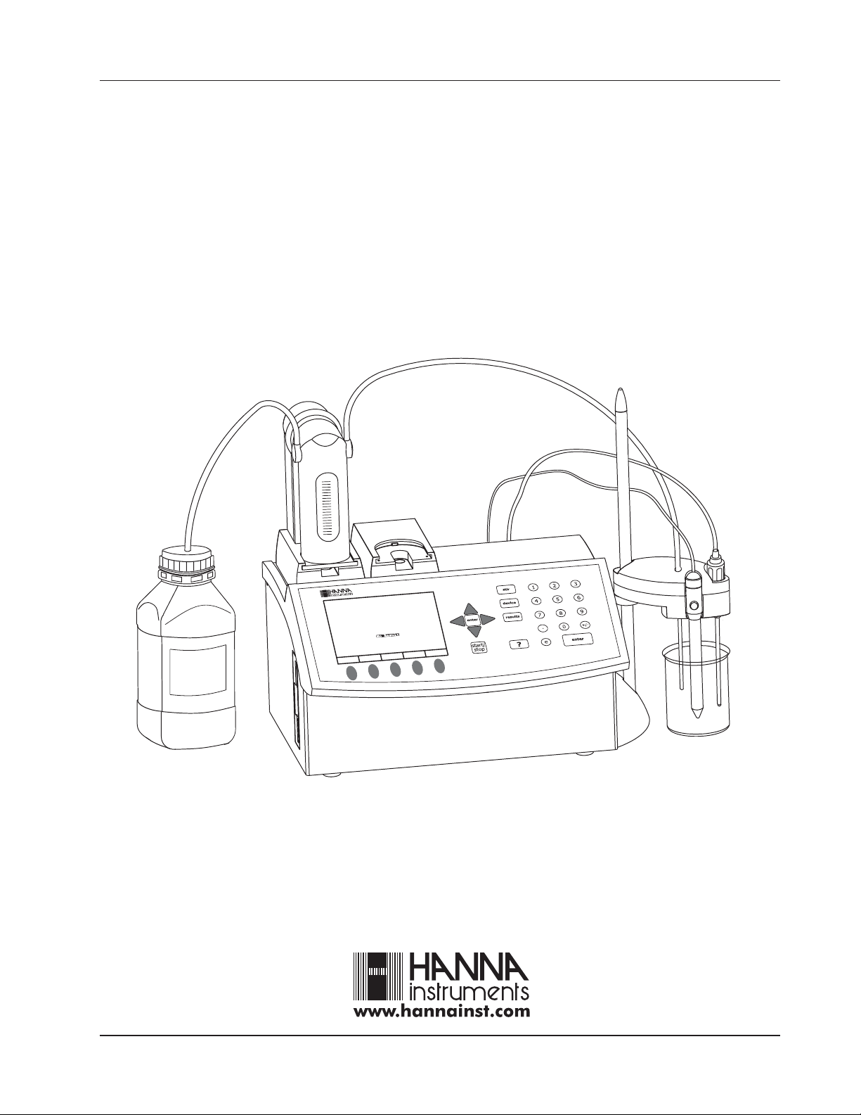
HI 901 / HI 902
AUTOMATIC TITRATOR
NaOH
0.1 M
1
H
O
a
N
0
e
z
i
d
r
a
d
n
a
t
S
C
T
A
S
l
a
r
e
n
e
G
M
s
n
o
i
t
p
O
.
c
n
o
C
t
n
a
r
t
i
T
)
L
/
q
e
(
N
0
0
0
.
l
u
s
e
R
o
N
e
d
o
r
t
c
e
l
E
V
t
n
i
o
p
d
n
E
o
h
t
e
M
t
c
e
l
e
o
i
t
p
O
d
o
h
t
e
M
P
R
0
0
3
1
/
0
0
3
1
t
l
o
d
n
H
p
e
m
u
V
m
/
H
p
e
t
t
e
r
u
B
s
3
0
0
2
,
2
1
v
o
N
1
3
:
4
4
:
5
Page 2

Page 3

TABLE OF CONTENTS
Chapter 1. INTRODUCTION
Chapter 2. SETUP
Chapter 3. USER INTERFACE
Chapter 4. GENERAL OPTIONS
Chapter 5. METHODS
Chapter 6. TITRATION MODE
Chapter 7. pH & mV MODE
Chapter 8. AUXILIARY FUNCTIONS
Chapter 9. MAINTENANCE, PERIPHERALS
Appendix 1. TECHNICAL SPECIFICATIONS
Appendix 2. BACK TITRATION (HI 902 only)
Appendix 3. MULTIPLE EQUIVALENCE POINTS (HI 902 only)
Appendix 4. ACCESSORIES
Page 4

Dear customer,
Thank you for choosing a Hanna Instruments Product.
This instruction manual has been written for the HI 901 / HI 902 Titrator products.
Please read this instruction manual carefully before using the instrument. This manual will
provide you with the necessary information for the correct use of the instrument.
© 2004 Hanna Instruments
All rights are reserved. Reproduction in whole or in part is prohibited without the written consent of the copyright
owner, Hanna Instruments Inc., 584 Park East Drive, Woonsocket, Rhode Island, 02895, USA.
Page 5

INTRODUCTION
1 INTRODUCTION
HI 901 and HI 902 are automatic titrators with high accuracy, great flexibility and repeatability.
The titrators are designed to perform a variety of potentiometric titrations, allowing the user
to obtain both good results and high speed analysis.
The main attributes of these titrators are:
Flexibility Support up to 100 titration methods (standard and user defined).
High accuracy Precise dosing system (under 0.1% accuracy).
Precise mV and pH measurements (± 0.1 mV and ± 0.001 pH accuracy).
Interpolated end point volume.
Repeatability Powerful built-in algorithms for equivalence point detection (first derivative and second
derivative detection algorithms, filtered derivatives option, settable range for equivalence
point detection).
Fixed end point mV or pH.
Quick results Standard titration methods.
Pre-titration dosing feature.
Dynamic / Linear dosing feature.
Complete report The results are displayed directly in the selected units.
Titration graph can be displayed on line and saved.
User customized reports can be printed, saved on floppy disk or transferred to PC via
RS232 interface.
The sample information and data stamp are included in the report.
Direct measurements The titrator can also be used for precise mV, pH and temperature measurements.
Report of data logging is available for direct measurements.
GLP features Up to 5 standardization points for the pH electrode.
Reminders for titrant age and standardization expiration.
Fields for specific annotations.
Large graphical display 7.5 B/W graphical display with backlight.
Easy to view text and graphs.
Lots of information on each screen.
Self diagnosis and Integrated help is available.
integrated help Self diagnosis features for peripheral devices including pump, valve, burette, stirrer.
Error management with warning and error messages.
Predefined troubleshooting titration methods.
This manual provides information regarding installation and functionality of the titrator, pointing
out hints and refined operation suggestions.
Before beginning to work with the titrator it is recommended to become familiar with its
various features.
1-1
Page 6

INTRODUCTION
1-2
Page 7

SETUP
Chapter 2. Contents
2 SETUP ................................................................................................... 2-3
2.1 Unpacking ............................................................................................. 2-3
2.2
Safety Measures
................................................................................... 2-4
2.3 Installation ........................................................................................... 2-5
2.3.1 Titrator Front View ...................................................
2.3.2 Titrator Rear View
........................................................
2.3.3 Titrator Left-side View ...........................................
2.3.4 Titrator Assembly ...................................................
2.3.4.1 Assembling Stirrer Stand and Support ....................................................... 2 - 6
2.3.4.2 Attaching Stirrer ..........................................
2.3.4.3 Connecting the Pump ........................................................................... 2 - 8
2.3.4.4 Attaching Burette Blank Support ....................
2.3.4.5 Attaching the Burette ......................................
2.3.4.6 Electrical Connections ......................................
2.3.5 Connection to Earth ....................................
..............................................
2.3.6 Floppy Disk Drive ...................................................
.......
...........
..............
............................ 2 - 5
.....
.......
.......
...
..............
.....
............................. 2 - 6
........
......
........................... 2 - 7
...........
.................
....................
......................................
.....
.............................. 2-11
..............
..................2 - 9
2-5
2-6
2-9
2-10
2-11
2-1
Page 8

SETUP
2-2
Page 9

2 SETUP
2.1 Unpacking
The titrator and the accessories are shipped in a single box containing:
ITEM QUANTITY
1 Titrator............................................................................... 1
SETUP
2 Pump Assembly.............................
3 Burette Assembly................................................................. 1
Burette (with 25 mL syringe)
Aspiration Tube with Fitting and Protection Tube
Dispensing Tube with Normal Dispensing Tip, Fitting,
Protection Tube and Tube Guide
Tube Locks
Tool for Valve Fitting and Burette Cap Removal
Light Spectrum Protection Screen
4 Stirrer Support, Stand, Collar and Positioning Screw................ 1
5 Burette Blank Support.......................................................... 1
6 Pump and Burette Locking Screws with Plastic Head................ 2
9 Temperature Sensor.............................................................. 1
10 Shorting Cap....................................................................... 1
11 Power Cable........................................................................ 1
12 RS232 Cable....................................................................... 1
13 Instruction Manual Binder...................................................... 1
14 Start-up Disk (FDD with Titrator Installation Kit)..................... 1
...
.................................. 1
15 HI 900 PC Application (FDD with Installation Kit).................... 1
16 Quality Certificate................................................................ 1
See Appendix 4 section A 4.3 Titrator components for pictures.
If any of the items is missing or damaged, please contact your sales representative.
Note: Save all packing materials until you are sure that the instrument functions correctly.
Any damaged or defective items must be returned in their original packing materials
together with the supplied accessories.
2-3
Page 10

SETUP
2.2 Safety Measures
The following safety measures must be followed:
1. Always ensure that the power-supply cable is connected to a grounded main power plug.
2. Never connect or disconnect the pump assembly with the titrator turned on.
3. Verify that the burette and the attached tubing are as described in this manual (see 9.1
Burette Maintenance section for more details).
4. Always check that the titrant bottle and the titration beaker are firmly sitting on a flat
surface.
5. Always wipe up spills and splashes immediately.
6. Avoid the following environmental working conditions:
Severe vibrations
Direct sunlight
Atmospheric relative humidity above 95% non-condensing
Environment temperatures below 10°C and above 40°C and a normal humidity range
Explosion hazards
7. Have the titrator serviced only by qualified service personnel.
2-4
Page 11
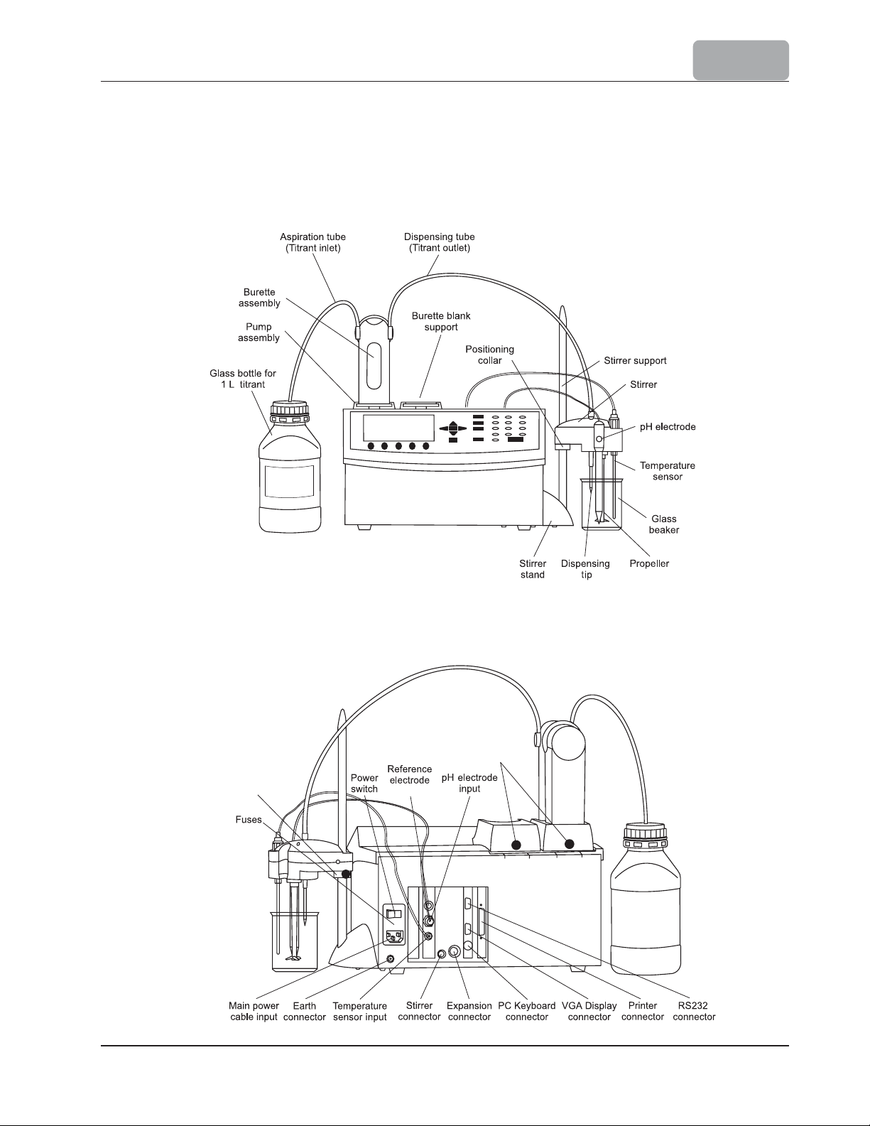
2.3 Installation
2.3.1 Titrator Front View
NaOH
0.1 M
SETUP
2.3.2 Titrator Rear View
Positioning collar
for stirrer adjustment
Locking screws
input
2-5
Page 12
SETUP
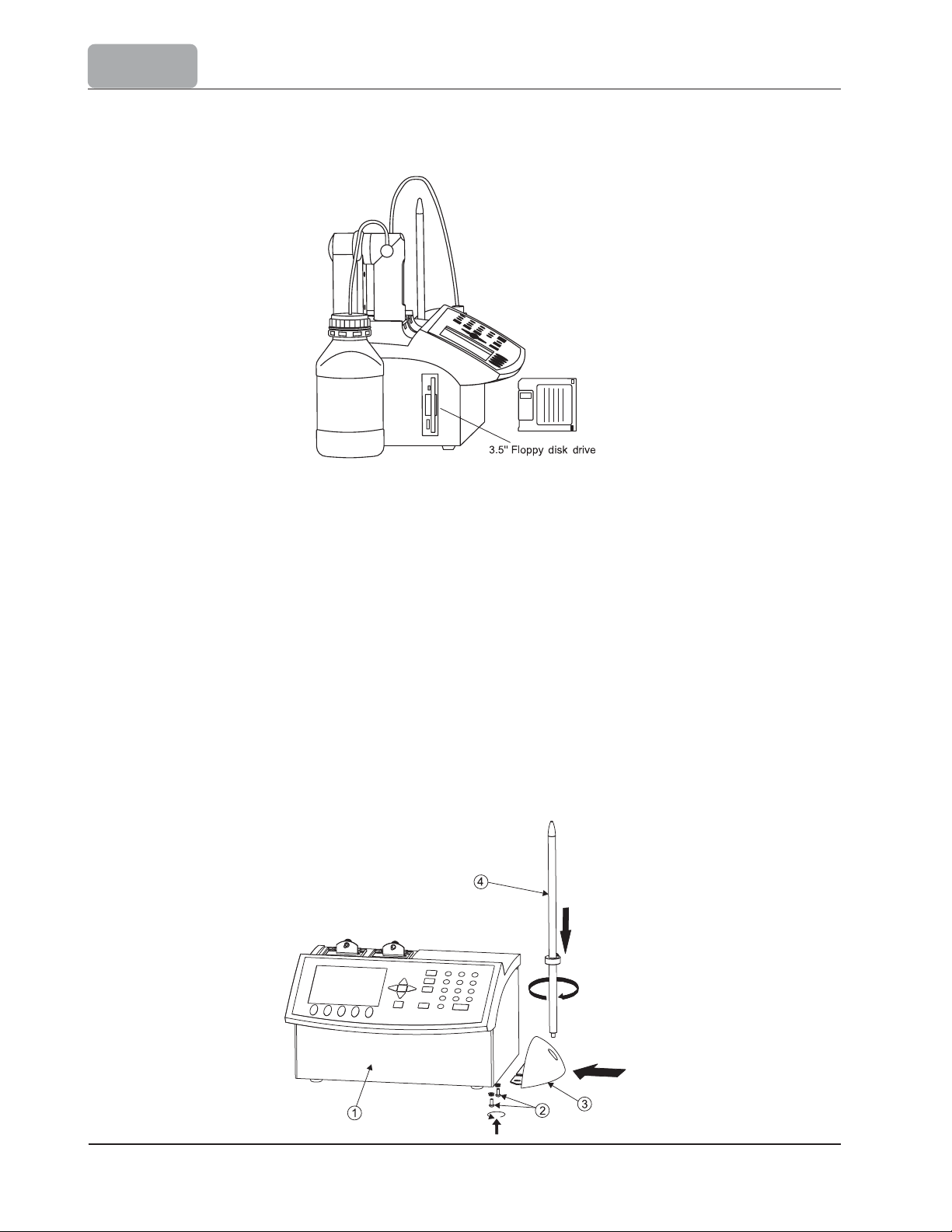
2.3.3 Titrator Left-side View
2.3.4 Titrator Assembly
Note: Assembly operations must be completed before connecting the titrator to the power-supply
voltage!
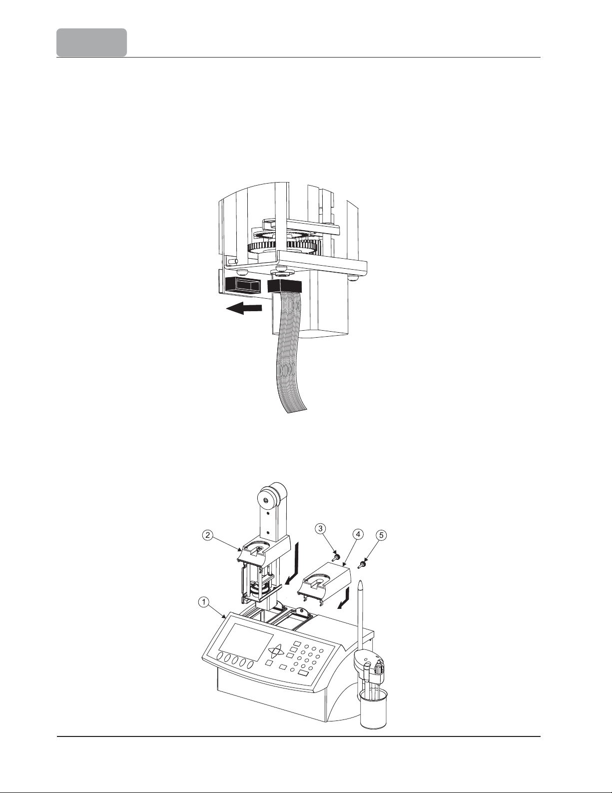
2.3.4.1 Assembling Stirrer Stand and Support
Follow these steps to assemble the stirrer:
Remove the screws (2) from the titrator chassis (1).
Attach the stirrer stand (3)
stand close to the wall of the chassis.
Tighten the stirrer stand (3) using the previously removed screws (2).
Screw the stirrer support (4) in the stirrer stand (3).
to the titrator chassis. Make sure
to position the stirrer
2-6
Page 13
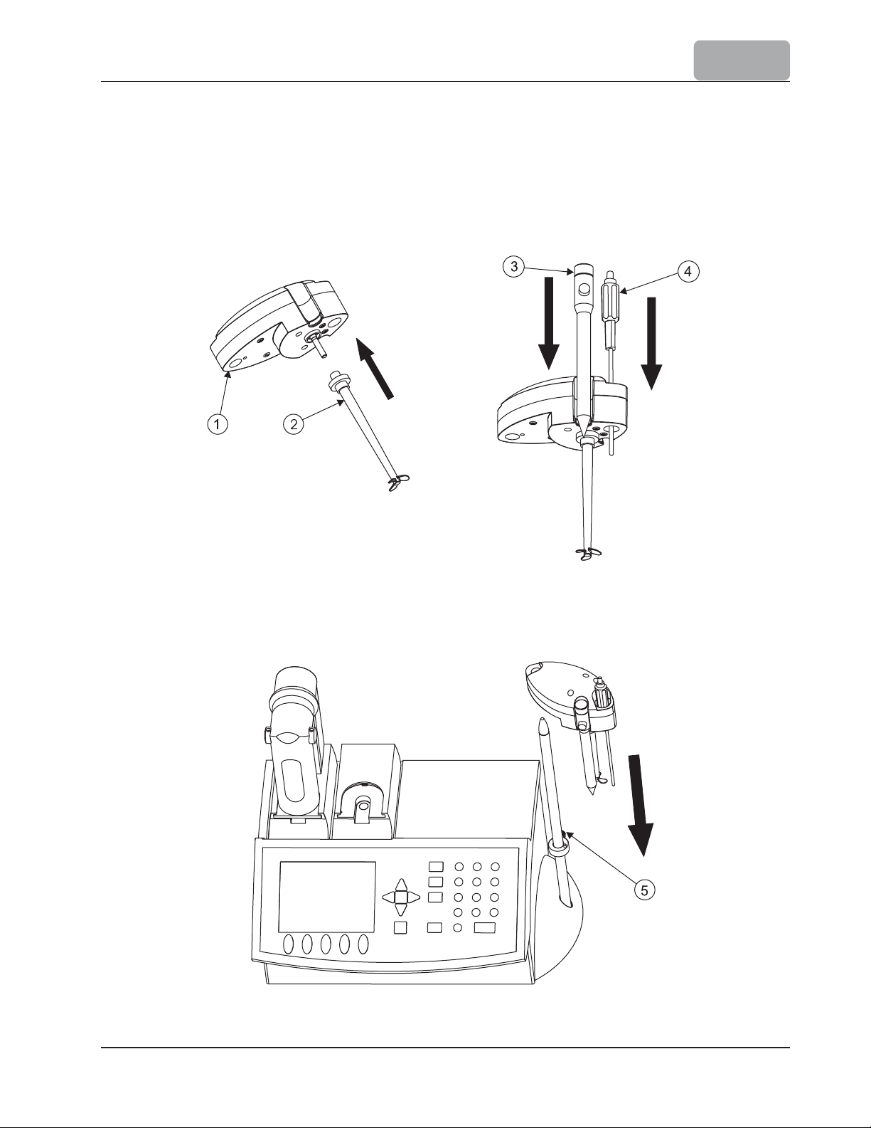
2.3.4.2 Attaching Stirrer
To attach the stirrer to titrator, follow these steps:
Attach the propeller (2) to the stirrer (1) by pressing it onto the stirrer shaft.
Insert the pH electrode (3) and temperature sensor (4) into the dedicated holes on
the stirrer. Push them in until they are tightened in a stable position.
SETUP
Slide the stirrer on the stirrer support and set the height by
located on the positioning collar (5).
tightening the
screw
2-7
Page 14
SETUP
2.3.4.3 Connecting the Pump
To connect the pump, follow these steps:
Retrieve the pump cable from inside the bay. The pump 1 connector is located in
left side bay.
Connect the cable to the pump as shown in the figure below. The pump connector is
located in the lower part of the pump, near the motor.
the
Insert the pump (2) into the dedicated bay. Lower the pump until it reaches the
lowest position, then slide it towards the front of the titrator chassis (1) until it is
firmly latched.
Secure the pump with the loking screw (3).
2-8
Page 15
SETUP
HI 902 only:
Follow the previous steps (2.3.4.3) to connect and attach the second pump.
2.3.4.4 Attaching Burette Blank Support (HI 901 only)
The burette blank support installation procedure is as follows:
Insert burette blank support (4) in the dedicated bay - on the right side (see the
previous picture). Lower the burette blank support until it reaches the lowest position,
then push it toward the front of the titrator chassis (1) until it is firmly latched.
Secure the burette blank support with the locking screw (5).
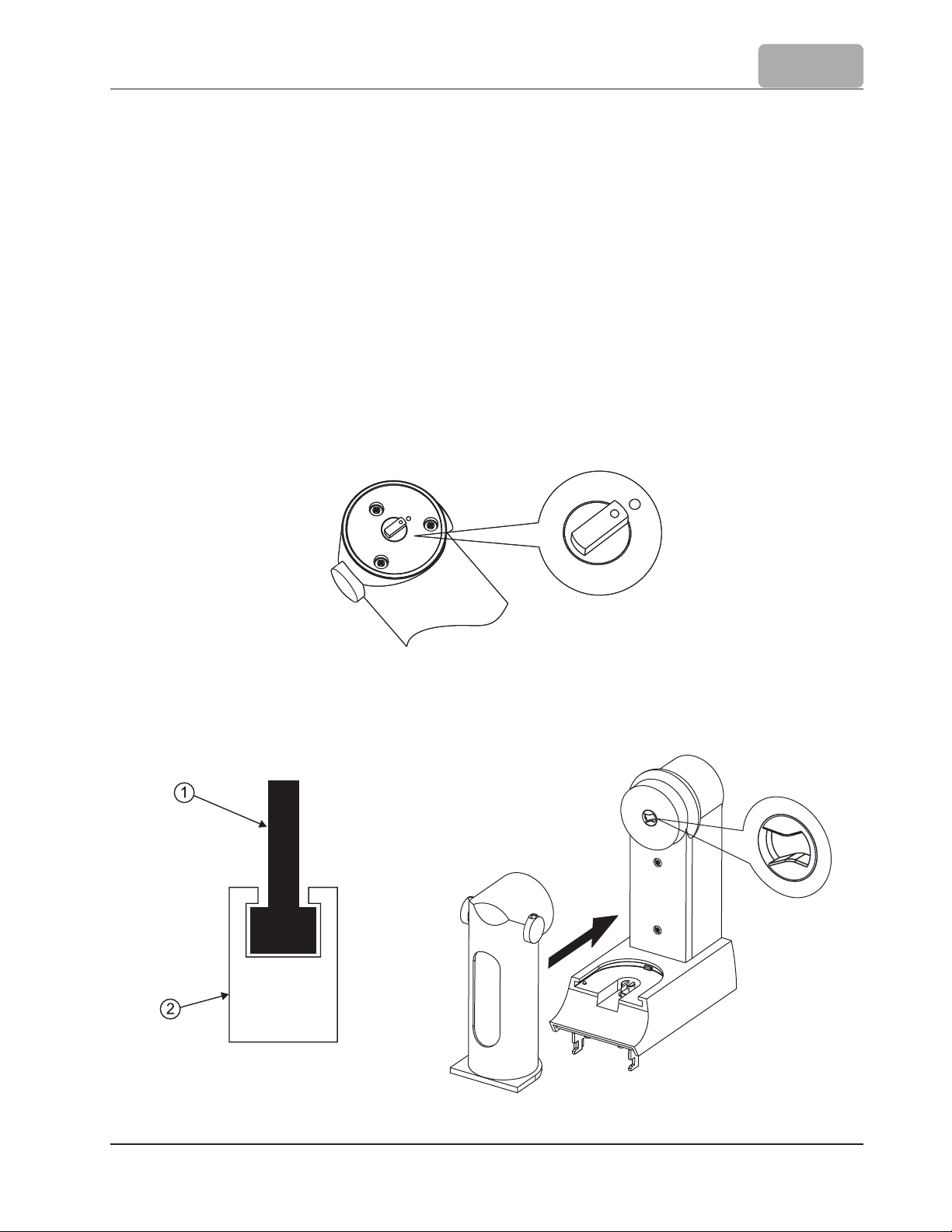
2.3.4.5 Attaching Burette
Make sure that the mark from the valve actuating cap and from the burette body are aligned
as shown in the figure below.
Take care to have a correct coupling between the pump plunger (2) and the syringe piston
(1) and also when sliding the burette onto its support, consider the alignment between the
valve actuating cap and the valve positioning wheel, as shown in the figure below.
2-9
Page 16
SETUP
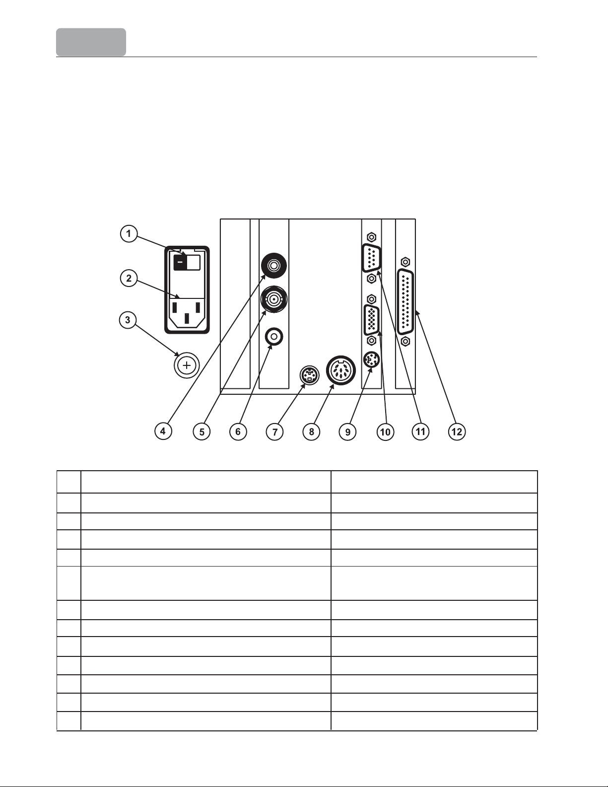
2.3.4.6 Electrical Connections
Connect the pH electrode to the BNC connector (5).
Connect the tempera
Connect the stirrer to the MINI-DIN connector (7).
Connect the power-supply cable to the power supply connector (2).
ture sensor to the RCA connector (6).
Nr Function Type of Connector
1 Power switch
2 Power supply (115, 230 VAC, 50-60 Hz) IEC Power line connector
3 Earth connector 5 mm screw
4 Reference electrode Ø 4 mm banana socket
5 Connection for pH or ORP indicating half-cell BNC socket
or combination electrodes (pH/mV)
6 Temperature sensor RCA socket
7 Stirrer 4-pin mini DIN
8 Connector for expansion device 8-pin DIN socket
9 External PC keyboard 6-pin mini-DIN (Standard PS2)
10 External display Standard VGA display 15-pin socket
11 RS232 interface Standard DB 9 pin socket
12 Printer standard DB 25pin socket
2-10
Page 17
SETUP
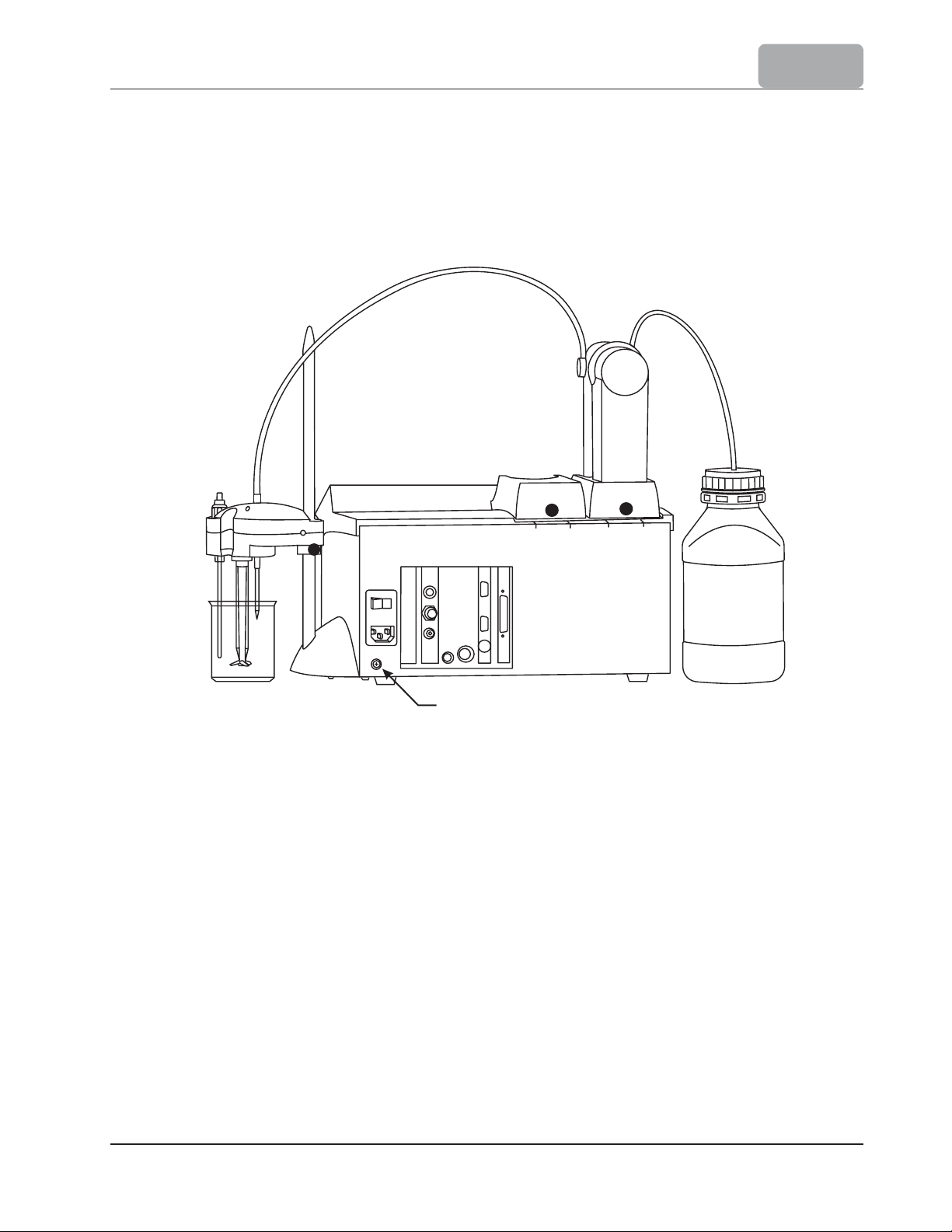
2.3.5 Connection to Earth
It is important that the titrator has a good connection to Earth. The titrator is properly
grounded through the power cord and for added confidence the unit can be connected to
Earth using the optional 5 mm screw and the nut connection located on the rear panel of
titrator.
Connect to Earth (optional)
2.3.6 Floppy Disk Drive
Report files, new created (user) methods, standard methods can be transferred to and
from the titrator using a standard 3.5 floppy disk.
2-11
Page 18

SETUP
2-12
Page 19

USER INTERFACE
Chapter 3. Contents
3 USER INTERFACE .................................................................................. 3-3
3.1 Start Up
...........................................
........................
..............................
3-3
3.2 Description ............................................................................................ 3-4
3.2.1 Keypad
3.2.1.1 Function Keys ..................................................................................... 3 - 4
3.2.1.2 Option Keys ...................................................
3.2.1.3 Arrow Keys .........................................
3.2.1.4 Numeric Keys .........................................................
3.2.1.5 Enter Key ........................................................
3.2.2 Display ...........................................................
3.2.3 The Main Screen ..........................................
3.3 Menu Navigation .......................................
...........................................................................
..................................... 3 - 4
.............
..........
....
.................................. 3 - 5
..........
....................
..............
........................... 3 - 5
................................... 3 - 6
........................................3-7
...
......................
.................. 3 - 5
............... 3 - 5
3-4
3.3.1 Selecting an Option ................................................................................... 3 - 7
3.3.2 Selecting a Menu Item ............................................................................... 3 - 7
3.3.3 Entering Text ....................
..........
...
....
.......................................................3 - 7
3.3.4 Saving Modifications .................................................................................. 3 - 8
3-1
Page 20

USER INTERFACE
3-2
Page 21
USER INTERFACE
3 USER INTERFACE
3.1 Start Up
Once the instrument is assembled and installed, please follow these steps to start up the
titrator:
Connect the instrument to a main power plug with ground wire. Make sure that the
voltage of the main power and the one specified on the titrator are the same.
Turn on the titrator from the power switch located on the back of the instrument.
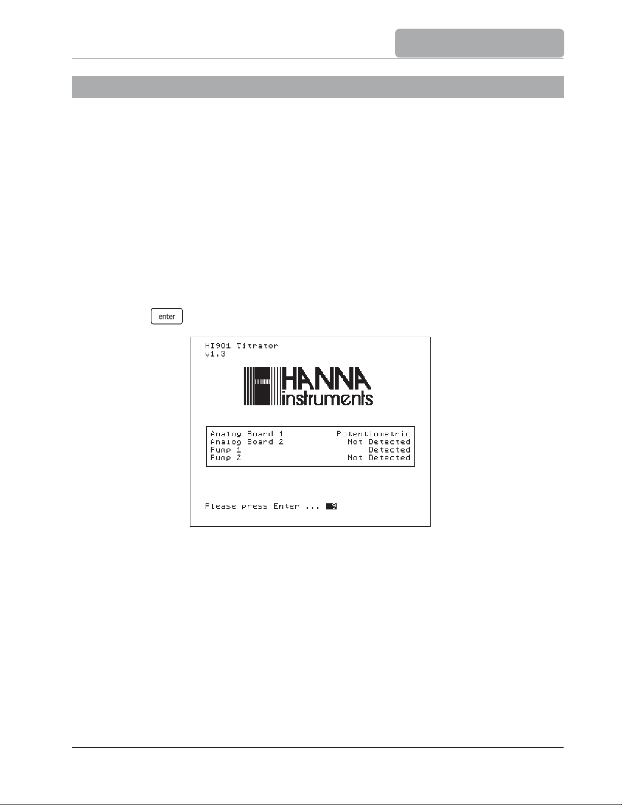
Wait until the titrator finishes the initialization process.
Note:
Press
All the performed initialization processes must be successfully completed. If one of
them is terminated by a Failed message, restart the titrator from the power switch.
If the problem persists, contact your dealer.
when prompted or wait a few seconds for titrator to start.
3-3
Page 22
USER INTERFACE
3.2 Description
This chapter describes the basic principles of navigating through the user interface, selecting
fields and entering values from the keypad.
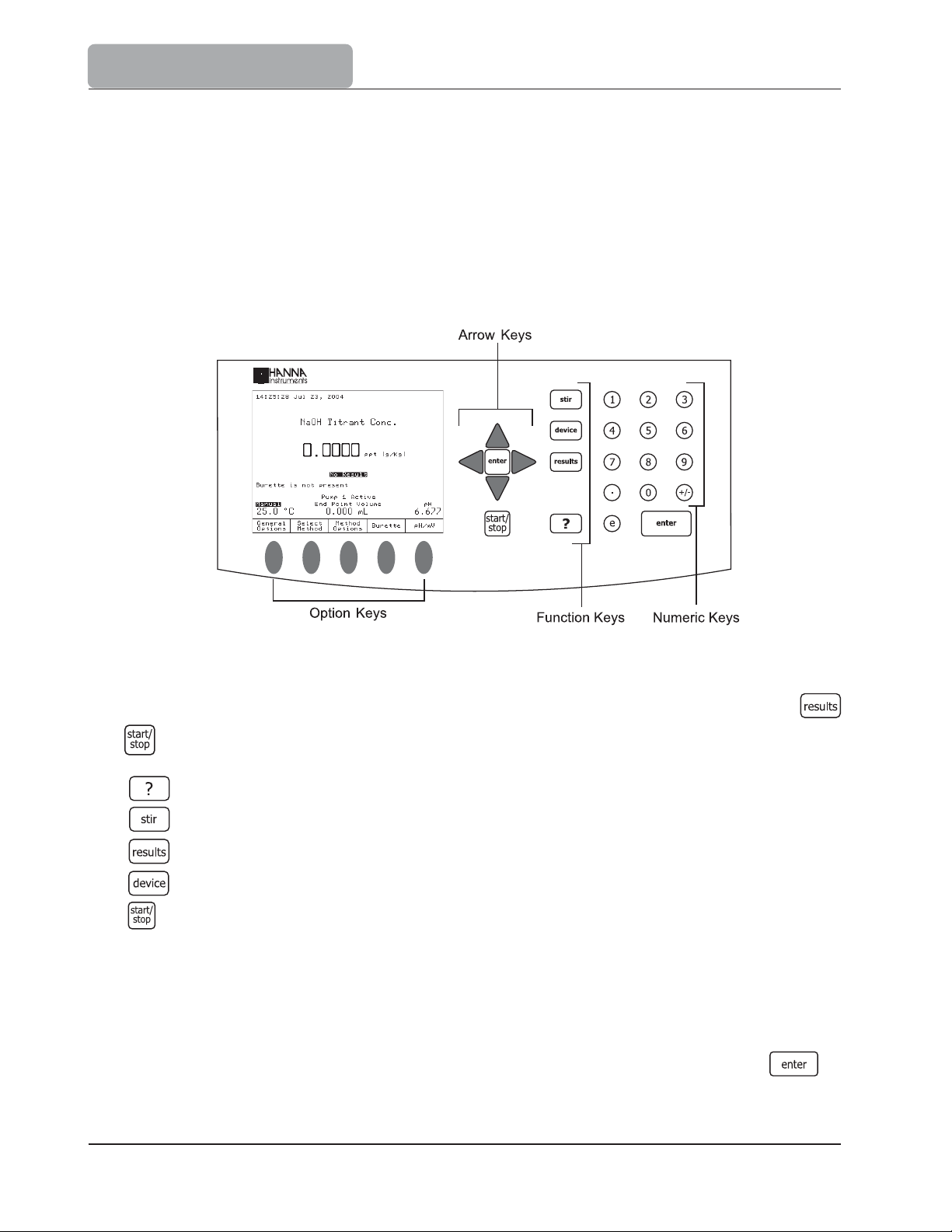
3.2.1 Keypad
The titrators keypad is grouped into four categories, as follows:
3.2.1.1 Function Keys
If one of these keys is pressed, the associated function is immediately performed. The
and keys are active only in specific screens:
Displays contextual Help
Turns the stirrer ON and OFF
Gives access to results menu
Reserved
Starts or stops a titration or data logging (when the titrator is in pH or mV mode)
3.2.1.2 Option Keys
These keys are assigned to the virtual-keys on the display. The significance of each option key
depends on the menu displayed on the screen.
The function related to an underlined virtual-key can also be activated by pressing .
3-4
Page 23
3.2.1.3 Arrow Keys
These keys have the following functions:
Move the on-screen cursor.
Increase and decrease the stirrer speed and other settings.
In the alphanumeric screen, to select a letter or to navigate through menu options.
3.2.1.4 Numeric Keys
Keys to - Used for numeric entries.
- Toggles between positive and negative values.
- Decimal point.
- Initiates entry of exponent for scientific notation.
3.2.1.5 Enter Key
USER INTERFACE
Both
, keys perform the same functions:
Accepts alphanumeric data entry.
Executes the default (underlined) virtual option key.
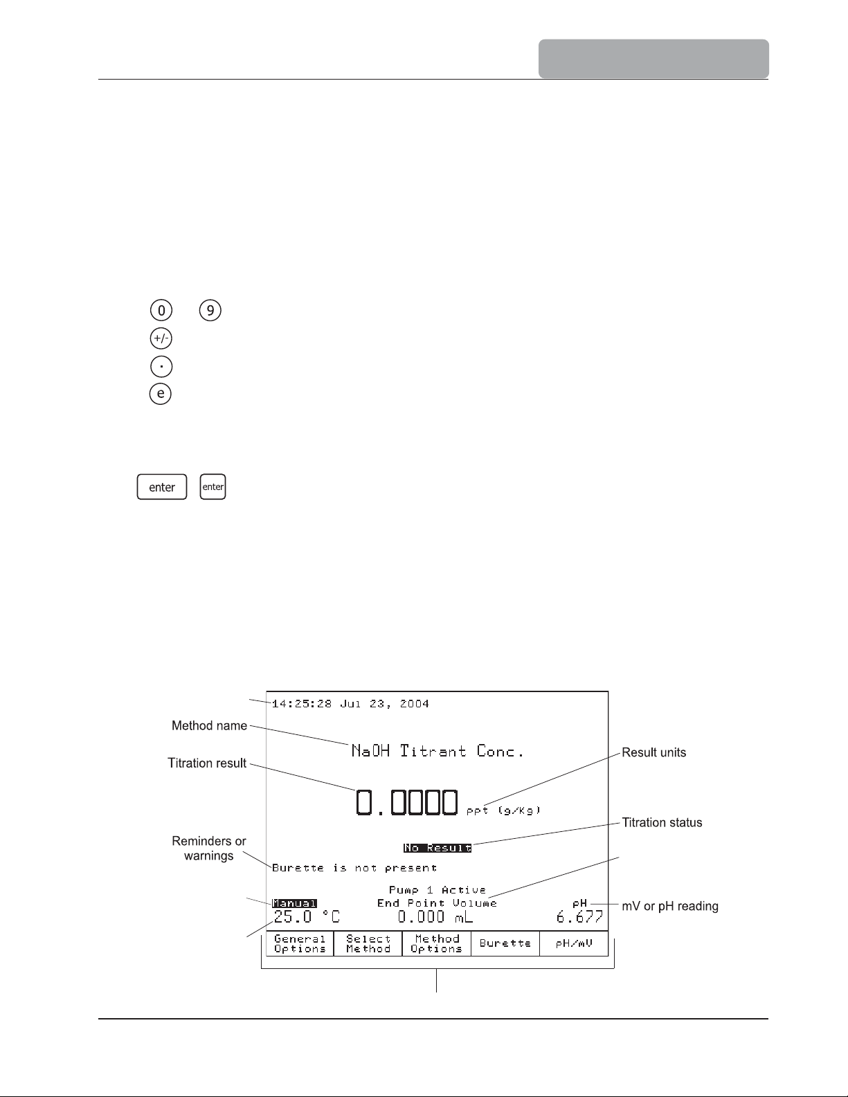
3.2.2 Display
The titrator has a large graphical display with built-in backlight.
explanations is presented below.
Time and date
Temperature
compensation
status
The main screen with short
End point volume
Temperature
reading
Virtual option keys
3-5
Page 24

USER INTERFACE
The user interface contains several screens. For each titrator function, one or more screens
are used.
Warnings and other critical information are displayed in reversed font.
3.2.3 The Main Screen
After start up and initialization, the first screen displayed is the main screen.
The main screen fields describe:
Method name: Displays the name of the selected method
Time and date: Displays the current date and time
Temperature reading: Displays the measured temperature
ATC: Indicates automatic temperature compensation
Manual: Indicates manual temperature compensation
Manual: Indicates manual temperature compensation as the temperature
probe is not connected
Stirrer information:
End point volume: Displays the volume delivered to reach the titration end point. When
Titration result: Displays the titration result
mV or pH reading: Displays the current readings. The sample reading will be: mV
mV: Indicates actual potential reading
rel mV: Indicates relative potential reading
pH: Indicates actual pH value
Titration status: Displays the status of the selected titration. When no titration was
Reminders: Indicates when a task needs to be performed and displays error
Pump 1 Active: Displays the current active pump
Actual / Set stirrer speed is displayed in RPM. When stirrer is off,
the stirrer information is not displayed
no titration has been performed, the displayed volume is 0.000 mL
or pH respectively
performed, No results is displayed
or warning messages
3-6
Page 25
3.3 Menu navigation
USER INTERFACE
3.3.1 Selecting an Option
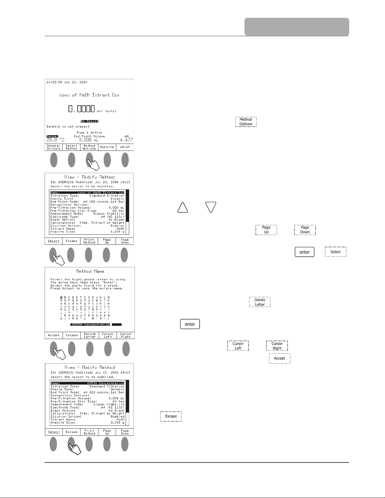
To select an option, simply press the option key below
the virtual option key. For example, to access the Method
Options screen press
.
3.3.2 Selecting a Menu Item
To select an item from the menu screen use the arrow
keys and to move the cursor.
When the menu is larger than the display, a scroll bar is
active on the right side. The and keys can
be used to scroll through the pages.
To activate the selected menu item, press or .
3.3.3 Entering Text
To enter text in an alphanumeric input box, first erase
the previous text by using .
To enter a letter, highlight it using the arrow keys then
press . Use the same procedure to enter the whole
name.
For editing, use the and keys.
When editing is complete, press .
The method name will be updated and displayed in the
name field of the View/Modify Method screen.
When all the desired parameters have been set, press
.
3-7
Page 26
USER INTERFACE
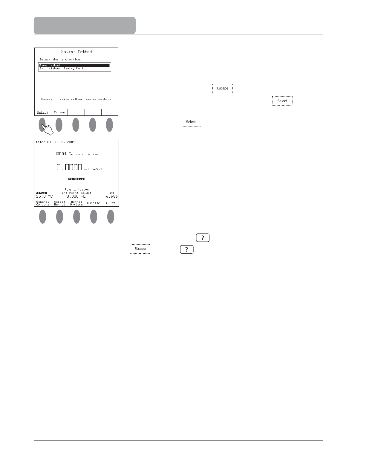
3.3.4 Saving Modifications
The Saving Method screen allows the user to save
the modifications. To exit from Saving Method screen
without saving, press
Saving Method option and then press . To save
the modifications highlight the Save Method option and
then press .
After the method name is changed, it appears in the method
name field.
Note: To access the contextual help menu, press at any time. Help is related to the
displayed screen. Press or press again to return to the previous screen.
or highlight the Exit Without
3-8
Page 27

Chapter 4. Contents
GENERAL OPTIONS
4 GENERAL OPTIONS ...................................................
4.1 Active Pump .................................................
4.2 Temperature .........................................................................................4-4
4.2.1 Temperature Source ..................................................................................4 - 5
4.2.2 Manual Temperature Setting .............................................
4.2.3 Temperature Units ................................................
4.3 Date and Time Setting ........................................
4.4 Display Settings ..................................................
4.5 Beeper ............................................................................
4.6 Stirrer .................................................................................................... 4-8
4.7 Language .........................................................................
...............
..........
............
...
........
...
..
........
.......................
................4-3
.....
..................4-3
...
...
.......................
..........
......
....
..............
............4 - 5
4-6
............. 4-6
........... 4-7
...
..........4-8
....... 4-9
4.8 Daily Standardization Rem
4.9 Periodic Standardization Remin
4.10 Total Volume Alert .......................................
4.11 Titrant Age Reminder ...........................................
4.12 Save Files to Diskette .....................................
4.13 Restore Files from Diskette ...................................................
4.14 Serial Link with PC ...............................................................
4.15 Reset to Default Settings ...............................
4.16 Update Software ................................................................................... 4-14
inder ............................................
der ..........................................
......................
...
..........
..........
...................
....
.................. 4-10
....
........................
.........
...................
.............. 4-10
........... 4-10
..............4-11
4-11
......
.........4-12
....... 4-13
4-14
4-1
Page 28

GENERAL OPTIONS
4-2
Page 29
GENERAL OPTIONS
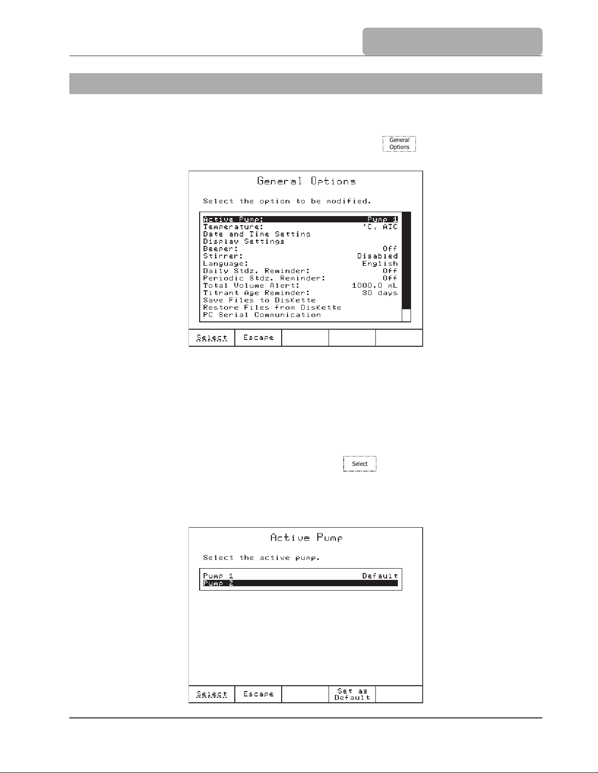
4 GENERAL OPTIONS
The General Options screen gives access to options that are not directly related to the titration
process or pH / mV measurement. To access this screen, press from the main screen.
The available menus are described below:
4.1 Active Pump
The HI 901 and HI 902 titrators can be equipped with one or two dosing systems (pump &
burette). Only one pump can be active at a time. This option allows the user to set active
either pump 1 or pump 2. Any further operations that involve the pump are referring to the
active one.
Highlight the Active Pump option and then press . The Active Pump screen is
displayed.
If there are two pumps connected to the titrator: use the arrow keys to select the active
pump as follows:
4-3
Page 30
GENERAL OPTIONS
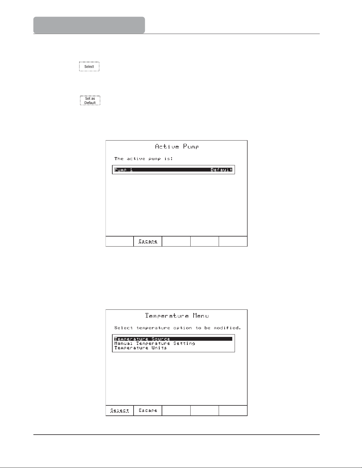
Highlight the pump to be activated.
Press and the highlighted pump is set as temporarily active (for the duration
of the current running session). After the titrator is restarted, the active pump will
be reset to the one set as default.
Press
session and all following running sessions.
If only one pump is connected to titrator, the Active Pump screen will be as follows:
and the highlighted pump is set as active immediately in the current
4.2 Temperature
The Temperature Menu screen allows selection of temperature source and other options
related to temperature.
4-4
Page 31

GENERAL OPTIONS
4.2.1 Temperature Source
The Temperature Source screen allows the user to select the temperature source, used
for pH temperature compensation.
When the Automatic Temperature Compensation option is selected, the temperature displayed
on the main screen is read by the temperature probe. Also the ATC icon is displayed.
When the Manual Temperature option is selected, a preset value of the temperature is used
for temperature compensation and the Manual icon is displayed on the main screen.
4.2.2 Manual Temperature Setting
If the temperature probe is not connected the user can manually set the temperature used by
the titrator for compensation. This can be done when the Manual Temperature option is
selected (see 4.2.1 Temperature Source section).
The temperature value can be set between 5 and 105 ºC.
4-5
Page 32

GENERAL OPTIONS
4.2.3 Temperature Units
The following temperature units can be selected.
The temperature ranges are as displayed in the Temperature Units screen.
The titrator will automatically convert the measured temperature to the new unit.
4.3 Date and Time Setting
This screen allows the user to set the date and time.
By pressing the cursor will cycle to the next field.
4-6
Page 33

GENERAL OPTIONS
4.4 Display Settings
This screen allows the user to customize the viewing features of the display.
Option Keys:
Turns the backlight off
Turns the backlight on
Increases the backlight saver time interval
Decreases the backlight saver time interval
The contrast can be adjusted using and keys.
The backlight intensity can be adjusted using and keys.
There are 8 gradual steps both for contrast and backlight intensity, ranging from 0 to 7.
A gray-scale grid ranging from black to white, is displayed in the center of the display,
allowing an easy selection of the appropriate display lighting.
The backlight saver option protects the display during stand-by periods, when no keys have
been pressed for a set amount of time.
If the display backlight is in Save mode, any keystroke will activate the display backlight
without performing any action.
The range for backlight saver interval is between 1 and 60 minutes. To disable the backlight
saver set it to 0 minute.
4-7
Page 34

GENERAL OPTIONS
4.5 Beeper
This screen allows the beeper to be enabled (Beeper On) or disabled (Beeper Off).
The beeper will sound after a titration is completed, when an invalid key is pressed or when
a critical error occurs during titration.
4.6 Stirrer
This screen allows the stirrer to be enabled or disabled.
4-8
Page 35

GENERAL OPTIONS
4.7 Language
Select the language from the available languages listed in this screen.
4.8 Daily Standardization Reminder
This screen allows a programmable reminder to appear when it is time to standardize the pH
electrode. The Standardize Electrode reminder message will appear each day at the
programmed time. Once standardization has been performed, the reminder will disappear
until the next day.
The reminder can be disabled by pressing .
4-9
Page 36

GENERAL OPTIONS
4.9 Periodic Standardization Reminder
This screen allows a programmable reminder to appear when it is time to standardize the pH
electrode.
electrode to be
Once the new standardization has been performed, the reminder will disappear and the
timer will reset.
The Standardize Electrode reminder message will appear when it is time for the
re-standardized.
The reminder can be disabled by pressing
.
4.10 Total Volume Alert
The Total Volume Alert screen allows a programmable reminder to appear when it is
time to add supplementary titrant to the glass titrant bottle. The current titrant volume data
will decrease as the titrant is used.
The Low Titrant Volume reminder message will appear when the available titrant volume
has decreased under 100 mL.
4-10
Page 37

GENERAL OPTIONS
After the new titrant volume has been set on titrator (in the Total Volume Alert screen), a
warning message appears reminding the user to perform titrant re-standardization.
The reminder can be disabled by pressing
The range is from 0 to 10,000 mL.
.
4.11 Titrant Age Reminder
This screen allows a programmable reminder to appear when it is time to verify the titrant
concentration or to change the titrant due to concentration confidence loss.
The Check Titrant Concentration reminder will appear when a number of days have passed
since the total volume alert was set or since the timer was restarted by pressing . The
reminder can be disabled by pressing .
The range is from 0 to 31 days.
4.12 Save Files to Diskette
This menu allows the user to save files from the titrator to a floppy disk.
On the titrator, the available file types are:
Standard Method Files - HI*.MTD
User Method Files - USER*.MTD
Report Files - *.RPT
If there is no diskette inserted in the floppy disk drive, the file manager menu is not available.
The selection of the file types can be performed with and keys. The number of files
and each file name on the titrator will be displayed.
For example, if no report file was found on the titrator the message 0 report files is
displayed. Corresponding messages are displayed for the other file types.
4-11
Page 38

GENERAL OPTIONS
The option keys allow the following operations:
Deletes the highlighted file
Deletes all currently displayed files
Copies the highlighted file from titrator to floppy disk
Copies all currently displayed files from titrator to floppy disk
Returns to the General Options screen
The status of the transfer (successful / unsuccessful) and the file name of the currently
processed file are displayed during copying or deleting.
When copying or deleting files is over, Press any key message appears and the instrument
returns to the list of files.
4.13 Restore Files from Diskette
This screen allows transfer of files from the floppy disk to the titrator.
4-12
Page 39

The file types that can be transferred are:
Standard Method Files - HI*.MTD
User Method Files - USER*.MTD
Report Files - *.RPT
GENERAL OPTIONS
Selection of the file types can be performed with the
The number of files and the name of each file found on the floppy disk is displayed on the
screen.
The option keys allow the following operations:
Deletes the highlighted file from diskette.
Deletes all currently displayed files from diskette.
Copies the highlighted file from diskette to titrator.
Copies all currently displayed files from diskette to titrator.
Returns to the General Options screen.
All the allowable operations are the same with the ones presented in 4.11 Save Files to Diskette
section.
and keys.
4.14 Serial Link with PC
In order to use this feature, the serial RS232 cable is needed to be connected between the
titrator and the PC. Make sure that HI 900 PC application is running on the PC.
In the Serial Communication screen:
Active / Inactive: shows the status of the serial link with the PC.
Active means that the titrator is using the RS232 serial communication with a PC and not
with other device.
Ready shows that the titrator is able to communicate with the PC.
During transfer of any information between the PC and the titrator, Transmit and information
about the percentage already transferred of current file are displayed.
4-13
Page 40

GENERAL OPTIONS
4.15 Reset to Default Settings
This option restores the manufacturer settings.
Note: Please be careful !!! This will also delete all the user created methods and restore all
manufacturer settings such as titrator configuration, standard method parameters, etc.
4.16 Update Software
This screen allows the user to update the titrator software from a floppy disk.
4-14
Page 41

Chapter 5. Contents
METHODS
5 METHODS ......................................................
5.1 Selecting Methods ................................................................................ 5 - 3
5.2 Standard Methods ................................................................................. 5 - 4
5.2.1 Upgrading Standard Methods .................................................................... 5 - 4
5.2.2 Deleting Standard Methods
5.2.3 Restore the Standard Methods to the Manufacturer Settings ........................... 5 - 5
5.3 User Methods ........................................................................................ 5 - 5
5.3.1 Creating User Methods .............................................................................. 5 - 6
5.3.2 Deleting User Methods ............................................................................... 5 - 6
5.4 View / Modify Method ...........................................................................5 - 7
5.5 Method Option .......................................................................................5 - 8
5.5.1 Naming the User Method ........................................................................... 5 - 8
5.5.2 Titration Type (HI 902 only) ...................................................................... 5 - 8
........................................................................ 5 - 5
........................................
5 - 3
5.5.3 Dosing Type ............................................................................................. 5 - 9
5.5.3.1 Linear Dosing ....................................................................................... 5 - 10
5.5.3.2 Dynamic Dosing .................................................................................. 5 - 11
5.5.4 End Point Mode ........................................................................................ 5 - 13
5.5.4.1 Fixed End Point (pH or mV) .................................................................... 5 - 13
5.5.4.2 Equivalence End Point (pH or mV) ........................................................... 5 - 14
5.5.5 Pre-Titration Volume ................................................................................. 5 - 20
5.5.6 Pre-Titration Stir Time .............................................................................. 5 - 21
5.5.7 Measurement Mode .................................................................................... 5 - 22
5.5.7.1 Signal Stability ...................................................................................... 5 - 22
5.5.7.2 Timed Increment ................................................................................. 5 - 24
5.5.8 Electrode Type ......................................................................................... 5 - 25
5.5.9 Blank Option ............................................................................................ 5 - 25
5.5.10 Imposed Current .................................................................................... 5 - 26
5-1
Page 42

METHODS
5.5.11 Calculation ............................................................................................5 - 27
5.5.11.1 Standard Titrations ............................................................................ 5 - 27
5.5.11.2 Back Titrations (HI 902 only) ...............................................................
5.5.12 Dilution Option ..................................................................................... 5 - 39
5.5.13 Titrant Name ........................................................................................ 5 - 40
5.5.14 Titrant Concentration ............................................................................5 - 40
5.5.15 Analyte Size .........................................................................................5 - 40
5.5.16 Analyte Entry ........................................................................................5 - 40
5.5.16.1 Fixed Weight or Volume ......................................................................5 - 41
5.5.16.2 Manual Weight or Volume ...................................................................5 - 41
5.5.17 Titrant 1 Entry (HI 902 only) .................................................................5 - 41
5.5.17.1 Calculated by Formula .......................................................................5 - 41
5.5.17.2 Fixed by User ..................................................................................5 - 41
5.5.18 Maximum Titrant Volume ...................................................................... 5 - 42
5.5.19 Stirring Speed .......................................................................................5 - 42
5.5.20 Potential Range ....................................................................................5 - 43
5.5.21 Volume/Flow Rate ................................................................................5 - 43
5.5.22 Signal Averaging ...................................................................................5 - 44
5 - 34
5.6 Printing ................................................................................................ 5 - 44
5-2
Page 43

METHODS
5 METHODS
The titrator automatically performs a complete analysis.
A complete analysis comprises sample preparation, dispensing of titrant solution, stirring,
measuring and waiting times, recognition of the end point and storing titration results.
All the parameters that a titration requires are grouped into a method.
The titrator is supplied with a pack of standard methods.
Using a floppy disk or connect the titrator to a PC using the HI 900 PC application, the
methods (standard and user methods) can be upgraded, stored or deleted.
5.1 Selecting Methods
To select a method, press from the main screen. A list of available methods will be
displayed.
In the Titration Methods screen, you can view the list of all available methods (standard
and user methods).
If no user method has been defined, only standard methods are displayed.
5-3
Page 44

METHODS
To select a method, highlight the method and press . The name of the selected
method will be displayed on the main screen.
5.2 Standard Methods
The standard methods are developed by the manufacturer for the most common types of
analysis. Also, each standard method can be used as a model to create a new user method.
Only specific method parameters can be modified by the user (see 5.5 Method Options
section).
5.2.1 Upgrading Standard Methods
The titrator will accept up to 50 standard methods.
To upgrade the titrator from Floppy Disk or PC with new standard methods, folow the steps
below:
Floppy Disk:
Insert the methods installation diskette into the floppy disk unit.
Press from the main screen.
Using and keys, highlight the Restore Files from Diskette option and choose
.
Using and keys, navigate through file types menu to find standard method
files. The list with available standard methods on the diskette will be displayed.
Press the or key to upgrade the titrator with the standard methods.
Press to return to General Options screen.
PC:
You can upgrade the titrator with standard methods from a PC, using HI 900 PC application
(see 4.14 Serial Link with PC section).
5-4
Page 45

METHODS
5.2.2 Deleting Standard Methods
You can remove unnecessary standard methods from titrator following the next steps:
Insert any diskette into the titrator.
From the main screen press .
Using the
Using the
method files. The available standard methods will be displayed.
Press the or keys to remove unnecessary standard methods.
Press
Also, you can remove standard methods from the titrator, using the HI 900 PC application
(see 4.14 Serial Link with PC section)
and keys, highlight the Save Files to Diskette option and press ;
and keys, navigate through the file types menu to find standard
to return to General Options screen.
5.2.3 Restore the Standard Methods to the Manufacturer Settings
You can restore the standard methods to the manufacturer setting by highlighting a standard
method and pressing .
Warning: Be careful, by pressing you will also delete all the user methods.
5.3 User Methods
User methods are defined by the user (usually by modifying a standard method).
The user methods can be developed in accordance with the requirements of the user. All
method parameters can be modified by the user.
5-5
Page 46

METHODS
5.3.1 Creating User Methods
To create a new user method start from a standard or user method and follow these steps:
Press from the main screen.
Using the and keys, highlight an existing method from the methods list.
Press . A new user method will be generated.
Press
Note: Only a limited number of user methods can be generated. If the limit of standard and user
methods (100 methods) is reached, a warning message will be displayed.
to activate the new created user method.
5.3.2 Deleting User Methods
To remove a user method, press from the main screen. Highlight the user method
that you want to delete and press . A screen will appear in order to confirm the
deletion. Press again to confirm, or press to cancel the operation.
5-6
Page 47

METHODS
5.4 View / Modify Method
To modify the methods parameters, press from the main screen. A list of all the
parameters for the selected method will be displayed. Using the
the option that you want to modify and choose
.
Save method:
From the View / Modify Method screen, press .
and keys, highlight
You can choose to save the modifications of the method parameters or to discard them.
5-7
Page 48

METHODS
5.4 Method Options
5.5.1 Naming the User Method
This option allows you to enter a name for the new method (up to 24 characters). Use the
arrow keys to navigate through the character table. Press
character to the method name.
to add the highlighted
5.5.2 Titration Type (HI 902 only)
In order to make an analysis you have to choose the type of titration:
Standard Titration
A titration with a pH or mV equivalence point detection.
A titration with fixed pH or mV end point.
5-8
Page 49

METHODS
Back Titration
A titration with a pH or mV equivalence point detection, consisting of two titration phases:
Phase 1 the sample is consumed by a known volume and concentration of titrant 1.
A sufficient amount of titrant 1 is dispensed to surpass the equivalence point in order
to react quickly with the sample.
Phase 2 the excess of titrant 1 is titrated with the titrant 2 to the equivalence point.
Finally, the concentration of the sample will be determined.
Also, if the Back Titration option is chosen, the following settings must be selected:
Titrant 1 pump: select the pump used in phase 1 of the titration (Pump 1).
Titrant 2 pump: select the pump used in phase 2 of the titration (Pump 2).
Break at titrant changing: select YES to stop titration temporarily, between the first and
the second phase of the back titration (you can do some tasks in order to perform the
analysis: eg. boiling the sample in order to evaporate the carbon dioxide).
5.5.3 Dosing Type
The Titrator allows two dosing types: Linear Dosing and Dynamic Dosing.
5-9
Page 50

METHODS
5.5.3.1 Linear Dosing
This type of dosing uses equal volume doses of titrant as shown in the graph below.
Linear Dosing
The Linear Dosing option is recommended for slower, difficult nonaqueous titrations or
certain specific analysis.
Note: For steep and normal titration curves, smaller volume increments are recommended, to
obtain many measured points around the equivalence point.
For flat titration curves, larger volume increments are recommended for equivalence
point detection.
To set the dosing volume, select Linear Dosing option and type the optimum dose.
5-10
Page 51

METHODS
The allowed ranges for dosing volume are:
0.001 to 4.500 mL for a 5 mL burette
0.001 to 9.000 mL for a 10 mL burette
0.005 to 22.500 mL for a 25 mL burette
0.005 to 45.000 mL for a 50 mL burette
5.5.3.2 Dynamic Dosing
The titrant is added in volumes that depends on the proximity of the end point as shown in
the graph below.
The titrator determines the titrant dose by trying to maintain a certain potential change (delta E)
with each addition.
If the potential jump, after the titrant dose, is lower than the set delta E, the next dose
volume is progressively increased until max Vol is attained. If the potential jump is still lower,
the titration will continue with the max Vol doses.
If the potential jump, after the titrant dose, is higher than the set delta E, the next dose
volume is progressively decreased until min Vol is attained. If the potential jump is still
higher, the titration will continue with the min Vol doses.
5-11
Page 52

METHODS
As a result, far from the end point, larger doses are made, reducing the total titration time.
Closer to the end point, smaller doses are made, providing more data and higher accuracy in
the critical end point region.
The following parameters must be set:
min Vol: Sets the smallest dose volume to be dispensed during titration.
The min Vol must be greater or equal than:
0.001 mL for a 5 mL burette
0.001 mL for a 10 mL burette
0.005 mL for a 25 mL burette
0.005 mL for a 50 mL burette
max Vol: Sets the largest dose volume to be dispensed during titration.
The max Vol must be lower or equal to 4.000 mL.
delta E: Sets the fixed potential jump that has to be achieved after each titrant dose.
The allowed range is between 0.1 and 99.9 mV.
Recommendations for dosing parameters:
For titrations with stepper titration curves the recommended settings are:
delta E = 3.5 to 9 mV
min Vol = 0.010 to 0.025 mL (for a 25 mL burette)
max Vol = 0.075 to 0.250 mL (for a 25 mL burette)
For titrations with flat titration curves the recommended settings are:
delta E = 10 to 15 mV
min Vol = 0.050 to 0.150 mL (for a 25 mL burette)
max Vol = 0.400 to 0.600 mL (for a 25 mL burette)
In order to achieve maximum accuracy and reproducibility, it is recommended that 20% to
80% of the nominal volume of the burette is consumed. If lower or higher volumes of titrant
are required, it is recommended to use the optimum burette volume as follows: 5, 10, 25 or
50mL.
5-12
Page 53

METHODS
5.5.4 End Point Mode
5.5.4.1 Fixed End Point (pH or mv)
Fixed End Point (pH):
The titration is normally terminated when the preset pH value has been exceeded. The
reported end point volume is interpolated between the dispensed volume when pH is under
the preset pH value and the dispensed volume when pH exceeded the preset pH value.
The range is from - 2.000 to 20.000 pH.
5-13
Page 54

METHODS
Fixed End Point (mV):
The end point detection algorithm is the same as for pH, but the threshold value is expressed
in mV.
The range is from - 2000.0 to 2000.0 mV.
5.5.4.2 Equivalence End Point (pH or mv)
The titration is normally terminated when the equivalence point is detected (the point where
the added quantity of titrant equals the quantity of analyte present in the sample, according
to the chemical combination ratio).
5-14
Page 55

Number of Equivalence Points (HI 902 only)
The titrator can perform a titration with more than one equivalence point.
Up to 5 equivalence points can be detected.
METHODS
End Point Determination
The first and the second derivative of the S-shaped titration curve can be used to detect the
equivalence point.
The equivalence point detection algorithm requires three more doses to be dispensed in the
analyte after the equivalence point is reached.
The reported end point volume is a calculated value based on a number of points around the
equivalence point.
The potentiometric S-shaped titration curve is the response in potential (mV) or pH between
the indication of the electrode versus cumulated addition of titrant. The graph takes the
shape of the S-character and can be expressed as mV or pH versus titrant volume.
The inflection point of the S-shaped titration curve is assumed to be the equivalence point of
the chemical reaction.
5-15
Page 56

METHODS
This is rigorously exact only for symmetric S-shaped titration curves. For non-symmetric curves,
the effect of this theoretical error can be minimized by smaller doses (more measurement
points) around the equivalence point.
1st Derivative:
When first derivative is used to recognize the equivalence point, the point where the first
derivative reaches the maximum value corresponds to the titration curve inflection point (EQP).
The detection algorithm searches for the maximum value of the first derivative. Also, the first
derivative must be greater than the threshold value at the maximum point (see Recognition
Options on page 5-17).
5-16
Page 57

METHODS
2nd Derivative:
When second derivative is used to recognize the equivalence point, the zero crossing point of
the second derivative corresponds to the titration curve inflection point (EQP).
The detection algorithm searches for the point where the second derivative changes the sign.
Also, the first derivative, corresponding to the checked point must be greater than the
threshold value (see Recognition Options on page 5-17).
Recognition Options
The Recognition Options screen represents a set of parameters used to avoid false
detection of the equivalence point. This could appear mainly due to the chemical system
(involved titrant / sample chemical species and concentrations) and / or to the electrode
response.
The Recognition Options screen is available only when Equivalence End Point (pH or mV)
option is selected.
5-17
Page 58

METHODS
Threshold:
This parameter must be set by the user in according with the analysis.
The threshold represents the absolute value of the first derivative, expressed in |mV/mL|
(absolute value), below which the detection algorithm does not search for the equivalence
point.
Range is between 1 and 9999 mV/mL.
The recommended value for the threshold is around 40% of the estimated maximum absolute
value of the first derivative.
Depending on the titration curve profile, the following guiding ranges might be used:
5-18
TITRATION CURVE PROFILE THRESHOLD |mV/mL|
FLAT 1 to 450
NORMAL 450 to 1800
STEEP 1800 to 9999
Page 59

METHODS
Range:
Range is an optional feature for equivalence point recognition. It represents a set mV or pH
range for equivalence point detection.
The Range option can be enabled by selecting YES in the Range Options screen.
Limit 1 - The first limit of the range attained during the titration:
This range can be from -2.000 pH to 20.000 pH (for pH equivalence point).
This range can be from -2000.0 mV to 2000.0 mV (for mV equivalence point).
Limit 2 - The second limit of the range attained during titration:
This range can be from -2.000 pH to 20.000 pH (for pH equivalence point).
This range can be from -2000.0 mV to 2000.0 mV (for mV equivalence point).
The Limit 2 value must not be equal to the Limit 1 value.
5-19
Page 60

METHODS
Filtered Derivatives:
Filtered Derivatives is an optional feature for equivalence point recognition.
This option adds a filtering procedure in the 1st and 2nd derivative computation algorithm
that reduces the influence of pH or mV noise.
The Filtered Derivatives option can be enabled by selecting YES in the Filtered Derivatives
Option screen.
Noise can appear due to:
Chemical system properties (sample, titrant, solvent), such as slow chemical reactions
or unbuffered samples such as wastewater, tap water, wine.
Electrode response.
Incorrect method parameters settings such as Signal Stability, Stirring Speed, etc.
Too small titrant doses.
Note: Even if false equivalence point detection has been highly diminished, a shift of the end
point volume might sometimes occur due to filtering. The shift is often at the level of
1 or 2 doses from the real equivalence point volume. For fast titrations and small
doses this is a useful option.
5.5.5 Pre-Titration Volume
During a regular titration, the equivalence point is reached after many doses are dispensed.
Most of these doses simply take up extra time while having no relevance for equivalence
point detection.
Pre-titration volume adds a large initial dose to jump directly to the proximity of the equivalence
point.
This first dose occurs after the pre-titration stir time is completed.
5-20
Page 61

The valid pre-titration volume is between the ranges shown below:
0.001 to 4.500 mL for a 5 mL burette
0.001 to 9.000 mL for a 10 mL burette
0.005 to 22.500 mL for a 25 mL burette
0.005 to 45.000 mL for a 50 mL burette
METHODS
If no pre-titration volume is used, 0.000 mL should be entered.
Note: A pre-titration volume is highly recommended whenever possible. When fewer linear
doses are used the overall titration duration considerably shortens.
5.5.6 Pre-Titration Stir Time
When this option is enabled, the sample is mixed for a period of time before the titration
begins. This allows the sample to become homogeneous.
The range is from 0 to 180 seconds.
If 0 seconds is entered, the Pre-Titration Stir Time option is disabled.
5-21
Page 62

METHODS
5.5.7 Measurement Mode
During titration, the acquisition of the potential (mV) value of the solution, can be performed
in two ways, by using either Signal Stability or Timed Increment option.
Addition of the next dose is performed immediately after the potential is measured.
5.5.7.1 Signal Stability
When Signal Stability option is selected, the titrator acquires the potential (from solution)
only when the stability condition is reached.
The response of the electrode for each added dose and the principles of the stability window
are plotted below and described on the following page.
5-22
Page 63

METHODS
The signal stability window (condition) represents the time interval ∆t during which the
potential measured in solution (mV) is confined inside the potential interval ∆E (see the
boxes on the chart).
The new signal value is acquired if the stability condition is reached but not before the
minimum waiting time (t min wait) has elapsed.
If the t max wait time has elapsed and the stability condition is not reached, the potential is
acquired (and a new dose is added).
delta E - is the height of the signal stability window.
The range is from 0.1 to 99.9 mV.
delta t -is the width of the signal stability window.
The range is from 0.5 to 10.0 seconds.
t min wait - is the minimum elapsed time before stability check. This is also the minimum
elapsed time between two doses.
The range is from 2 seconds to t max wait time.
t max wait -is the maximum elapsed time between two successive doses. If the t max wait
has elapsed, a new dose is added even if the condition of signal stability is not
reached.
The range is from t min wait time to 180 seconds.
5-23
Page 64

METHODS
5.5.7.2 Timed Increment
When Timed Increment option is selected, the acquiring of the potential (mV) value from the
solution is made at a fixed time interval (no signal stability check).
The time period between two acquisitions must be set according with the used reaction and
the time response of the electrode.
The range is from 2 to 180 seconds.
5-24
Page 65

METHODS
5.5.8 Electrode Type
Enter the type of the electrode, up to 24 characters. The electrode type will appear in the
titration report.
5.5.9 Blank Option
This feature allows the user to select the procedure for the blank calculations (where V is the
volume of titrant dispensed during the titration and Blank is the volume of titrant consumed
by the blank sample).
5-25
Page 66

METHODS
If one of the options (V-Blank or Blank-V ) is selected in the View / Modify Method screen
the Blank Value option will became active and the value of blank can be set (in liters).
5.5.10 Imposed Current (HI 902 only)
When Fixed End Point (mV) (see 5.5.4 End Point Mode) is set, the Imposed Current
option will become available.
Using the imposed current feature in end point redox titrations has a great advantage on the
speed of the redox reactions. The speed is increased significantly when the double Pt electrode
used for the titration is polarized with a small imposed current (we obtain a stepper jump,
perfect adapted for end point titrations).
In order to use this feature you must install the HI 900401 imposed current analog board.
5-26
Page 67

METHODS
The imposed current can be set from -100 µA to 100 µA with 1 µA resolution.
5.5.11 Calculations
The titrator will make certain calculations in order to obtain the result of the analysis. The
result is computed starting from the end point volume (titrant volume at the equivalence
point), using a formula set by the user.
5.5.11.1 Standard Titrations
Edit Variable Values
This option allows the user to change the values of the variables used in a previously selected
calculation.
For each formula, selected variables can be changed.
No Formula (mL only)
If this option is selected, only delivered milliliters (mL) are displayed.
5-27
Page 68

METHODS
Sample Calculations by Weight
This calculation should be used when the concentration of an analyte is determined in a solid
sample. The results are based on the initial sample weight (in grams). When you choose this
formula, select the Titrant Unit first and then the Final Result Unit.
The titrator will provide the results based on the titrant and sample units selected.
Titrant Units:
M (mol/L) (moles/liter)
N (eq/L) (equivalences/liter)
g/L (grams/liter)
mg/L (milligrams/liter)
Final Result Units:
ppt (g/Kg) (parts per thousand; grams/kilogram)
ppm (mg/Kg) (parts per million; milligrams/kilogram)
ppb (µg/Kg) (parts per billion; micrograms/kilogram)
% = g/100 g (percentage in weight; grams/100 grams)
mg/g (milligrams/gram)
mg/Kg (milligrams/kilogram)
mol/Kg (moles/kilogram)
5-28
mmol/g (millimoles/gram)
eq/Kg (equivalences/kilogram)
meq/Kg (milliequivalences/kilogram)
Page 69

METHODS
If the titrant unit is selected as M (mol/L) and the final sample unit as g/Kg (grams/kilogram)
the formula used to generate the result is displayed below:
Some variables can be set according to the amount of sample and titrant used.
Sample Calculations by Volume
This calculation should be used when the concentration of an analyte is determined in a
liquid sample. The results are based on the initial sample volume (in milliliters). When
choosing the formula, select the Titrant Unit first and then the Final Sample Unit.
The titrator will perform the calculation based on the titrant and the sample units selected.
Titrant Units:
M (mol/L) (moles/liter)
N (eq/L) (equivalences/liter)
g/L (grams/liter)
mg/L (milligrams/liter)
Final Sample Units:
ppt (g/L) (parts per thousand; grams/liter)
ppm (mg/L) (parts per million; milligrams/liter)
ppb (µg/L) (parts per billion; micrograms/liter)
5-29
Page 70

METHODS
M (mol/L) (Molarity; moles/liter)
N (eq/L) (Normality; equivalences/liter)
mg/L (milligrams/liter)
µg/L (micrograms/liter)
mmol/L (millimoles/liter)
mg/mL (milligrams/milliliter)
g/100 mL (grams/100 milliliters)
eq/L (equivalences/liter)
meq/L (milliequivalences/liter)
If the titrant unit is selected as N (eq/L) and the final sample unit as g/L (grams/liter), the
formula used to generate the result is displayed below.
Some variables can be set according to the amount of sample and titrant used.
Standardize Titrant by Weight
This calculation should be used when the titrant is standardized (concentration
determination) using a solid standard. Determination of the titrant concentration is based
on the primary standard weight (in grams).
5-30
Page 71

METHODS
The titrator will provide the calculation based on the titrant unit selected.
Standardize Titrant by Volume
This calculation should be used when the titrant is standardized (concentration determination)
using a standard solution. Determination of the titrant concentration is based on the primary
standard volume (in milliliters).
The titrator will perform the calculation based on the titrant unit selected.
Generic Formula
This option allows the user to define their own calculation formula of the final analyte
concentration in a solid or liquid sample. The variables can be set to reach any final result
from the list below:
ppt (g/Kg) (parts per thousand; grams/kilogram)
ppt (g/L) (parts per thousand; grams/liter)
ppm (parts per million; milligrams/kilogram)
ppm (mg/L) (parts per million; milligrams/liter)
ppb (parts per billion; micrograms/kilogram)
ppb (µg/L) (parts per billion; micrograms/liter)
% = g/100 g (percentage in weight; grams/100 grams)
M (mol/L) (Molarity; moles/liter)
mg/g (milligrams/gram)
N (eq/L) (Normality; equivalences/liter)
mg/Kg (milligrams/kilogram)
mg/L (milligrams/liter)
mol/Kg (moles/kilogram)
µg/L (micrograms/liter)
mmol/g (millimoles/gram)
eq/Kg (equivalences/kilogram)
mmol/L (millimoles/liter)
meq/Kg (milliequivalences/kilogram)
mg/mL (milligrams/milliliter)
g/100 mL (grams/100 milliliters)
5-31
Page 72

METHODS
eq/L (equivalences/liter)
meq/L (milliequivalences/liter)
The formula can be used either for titrant standardization or for sample analysis.
C*V*F1*F2*F3
S
Where:
5-32
C = the concentration of the titrant
F1 = general factor
F2 = general factor
F3 = general factor
S = sample size, in grams or milliliters
V = the volume delivered, in liters, to reach the preset or equivalence end point
(determined by the titrator)
Page 73

METHODS
Titrant Concentration:
The units for titrant concentration can be:
mol/L (concentration unit of titrant)
eq/L (concentration unit of titrant)
g/L (concentration unit of titrant)
mg/L (concentration unit of titrant)
One of the general factors should be used as a stoichiometric factor, the other as unit
conversion factor and the third as weight conversion factor.
Chemical combination factor:
The chemical combination factor is the chemical combination ratio between the analyte and
titrant or standard and titrant.
In the particular case that the combination ratio is expressed in moles, this factor is called the
stoichiometric factor.
This factor can be one of the following:
mol/mol (moles of sample/moles of titrant)
mol/eq (moles of sample/equivalence of titrant)
eq/mol (equivalences of sample/moles of titrant)
mol/mol (moles of titrant/moles of standard)
eq/mol (equivalences of titrant/moles of standard)
Examples: 2 moles of NaOH react with 1 mole of H2SO
Unit Conversion factor:
Used to convert between various measurement units.
Examples: L/1000 > mL
g/1000 > mg
Weight Conversion factor:
Used to convert between weight measurement bases (Kg, g, mg, µg or mole, mmole).
Example: g > mol
4
5-33
Page 74

METHODS
5.5.11.2 Back Titrations (HI 902 only)
Sample Calculations by Weight
When choosing this formula, select the titrant 1 unit, the titrant 2 unit and then the final
result unit.
5-34
Page 75

METHODS
If the titrant 1 unit is selected as M (mol/L), titrant 2 unit is selected as M (mol/L) and the
final result unit as mg/g (milligrams/gram) the following formula is used to calculate the
amount of titrant 1 (used in the first stage of back titration or direct titration) and will be as
follows:
The formula is based on an approximation: the sample concentration is 100% w/w.
With this approximation, the titrator will calculate the volume of titrant 1 needed to consume
the sample and multiply it with an excess factor in order to raise or to lower the amount of
titrant 1 dispensed.
Some variables can be set according to the amount of sample and titrant 1 used.
When the parameters from the formula are set, press to proceed with the next
formula used in the back titration algorithm.
If you do not want to use the Calc. Direct Titr. Volume formula, then from the View / Modify
Method screen:
highlight the Titrant 1 Entry option, press .
highlight Fixed Weight or Volume option and press , you will be prompted to
type the volume of titrant 1 to be dispensed in the first stage of back titration.
This formula is used to calculate the remaining volume of titrant 1 after the reaction with the
sample.
5-35
Page 76

METHODS
In order to calculate this volume, the remaining titrant 1 volume is titrated (pH/mV equivalence
point titration) with titrant 2.
After the excess volume of titrant 1 is calculated, the following formula is used to calculate
the exact volume of titrant 1 that was consumed by the sample:
V1 = V1tot V1excess
When all the parameters are set, press to proceed with the Calculating Sample
Concentration formula:
Sample Calculations by Volume
When choosing formula, follow these steps:
⇐ First select the titrant 1 unit
5-36
Page 77

METHODS
⇐ Select the titrant 2 unit
⇐ Select the final result unit
The titrator will provide the calculation based on the titrants and sample units selected.
After you have selected the titrant 1, titrant 2 and the final result units the titrator will display
a screen with a formula used to calculate the amount of titrant 1 (used in the first stage of
back titration).
5-37
Page 78

METHODS
This calculation formula is used as an approximation of the sample concentration (sample
max conc.). This formula can be used when we have an expected sample concentration (eg.
we know that the sample concentration must be around 1 M (mol/L)).
If we dont have an expected sample concentration, then from the View/Modify Method screen:
highlight the Titrant 1 Entry option, by pressing
highlight Fixed By User option and press
volume of titrant 1 to be dispensed in the first stage of the back titration.
With this approximation, the titrator will calculate the volume of titrant 1 needed to consume
the sample and multiply it by an excess factor in order to raise or to lower the amount of
titrant 1 dispensed.
When the parameters from the formula are set, press to proceed to the next formula
used in the back titration algorithm.
This formula is used to calculate the remaining volume of titrant 1 after the reaction with the
sample.
, you will be prompted to type the
.
In order to calculate this volume, the remaining volume of titrant 1 is titrated (pH/mV
equivalence point titration) with the titrant 2.
After the excess (remaining) volume of titrant 1 is calculated, the following formula is used
to calculate the exact volume of titrant 1 that was consumed by the sample:
V1 = V1tot V1excess
5-38
Page 79

METHODS
When all the parameters are set, press to proceed with the Calculating Sample
Concentration formula:
Generic Formula
This option allows the user to define their calculation formula for the Direct Titration Volume,
Calculating Excess Volume of Titrant 1 and Final Sample Concentration in a solid or liquid
sample.
5.5.12 Dilution Option
This option enables the dilution calculations to be made (when the initial sample is diluted,
the titration is made with an aliquot of the diluted sample).
The calculations are made for the sample weight (volume) in order to express the results for
the initial sample.
Final Dilution Volume: The volume of the sample after the dilution process.
Aliquot Volume: The volume of the aliquot (sample volume used for the titration)
Analyte size to be diluted: The initial sample weight (volume)
5-39
Page 80

METHODS
The sample size used in the calculations will be:
Analyte size to be diluted * Aliquot Volume
Final Dilution Volume
5.5.13 Titrant Name
Enter the name of the titrant (up to 24 characters). This name will appear in the titration
report.
5.5.14 Titrant Concentration
Enter the concentration of the titrant to be used. When determining the titrant concentration
only the unit is displayed and the titrant concentration can not be set.
5.5.15 Analyte Size
Enter the size of the sample (for sample concentration determinations) or standard (for
titrant concentration determination).
5.5.16 Analyte Entry
With this option select the entry type mode of the analyte.
5-40
Page 81

METHODS
5.5.16.1 Fixed Weight or Volume
Each titration will use the same analyte weight or volume as preset in the calculations.
5.5.16.2 Manual Weight or Volume
Each titration will use a different analyte weight or volume. The titrator will prompt for the
analyte volume at the beginning of each titration.
5.5.17 Titrant 1 Entry (HI 902 only)
Select the mode for evaluating the necessary quantity of titrant 1 used in the back titration
process (phase 1).
5.5.17.1 Calculated by Formula
The volume of titrant 1 to be dispensed in the phase 1 of back titration will be calculated by
formula (see Calc. Direct Titr. Volume screen on page 5-35).
5.5.17.2 Fixed by User
Fixed volume of titrant 1 will be used during the first phase of back titration process (direct
titration).
5-41
Page 82

METHODS
5.5.18 Maximum Titrant Volume
The maximum titrant volume used in the titration must be set according to the analysis.
If the titration end point (fixed or equivalence End Point) is not reached, the titration will be
abnormally terminated after the maximum titrant volume has been dispensed. The error
message (Limits Exceeded) will appear on the display.
Range is from 0.100 to 100.000 mL.
5.5.19 Stirring Speed
The stirring speed can be set between 100 and 2500 RPM with 100 RPM resolution.
The preset value of stirrer speed from the current method is used during the entire process,
as long as the method is set as active.
Also, the speed can be adjusted using the and keys when the stirrer is on.
5-42
Page 83

METHODS
5.5.20 Potential Range
The allowable input potential range can be set by the user. Outside of these limits, if the
titration is in progress, the titration will be abnormally terminated and an error message will
appear.
These limits provide protection against a titration that does not generate an end point due to
potential over-range.
The ranges must be set within -2000.0 to 2000.0 mV.
5.5.21 Volume/Flow Rate
The flow rate for the dosing system can be set by the user in an interval of 0.1 to twice the
total burette volume, as follows:
0.1 to 10 mL/min for a 5 mL burette
0.1 to 20 mL/min for a 10 mL burette
0.1 to 50 mL/min for a 25 mL burette
0.1 to 100 mL/min for a 50 mL burette
Note: The titrator automatically detects and displays the burette size.
The flow rate is set for all burette operations.
5-43
Page 84

METHODS
5.5.22 Signal Averaging
This option enables or disables a filtering on the mV/pH reading.
If 1 Reading is selected, the filtering is disabled. Otherwise, the titrator will take the last reading
and place it into a moving window along with the last 2, 3 or 4 readings (depending on the
selected option). The average of those readings is displayed and used for calculations.
Averaging more readings is helpful when a noisy signal is received from the electrode.
5.6 Printing
To print method parameters, press from the main screen.
Press and wait a few seconds until the printer completes the job.
If no printer is connected to the dedicated socket, or if the printer is offline, an error message
will appear on the display (see 9.3.3 Connecting a Printer section, for information about
connecting a printer to the titrator).
5-44
Page 85

TITRATION MODE
Chapter 6. Contents
6 TITRATION MODE .................................................................................6-3
6.1 Titration Start .......................................................................................6-3
6.1.1 In Progress Titration ................................................................................. 6 - 3
6.1.2 Suspend Titration ..................................................................................... 6 - 3
6.1.3 On-line Graph .......................................................................................... 6 - 3
6.2 Titration Stop ........................................................................................6-5
6-1
Page 86

TITRATION MODE
6-2
Page 87

TITRATION MODE
6 TITRATION MODE
6.1 Titration Start
Before beginning to perform a titration make sure that the following conditions are met:
A pump is properly installed and selected as active.
A burette is inserted in the pump and filled with titrant.
The aspiration tube is inserted in the titrant bottle and the dispensing tube is over
the analyte beaker.
The electrode and the temperature probe is inserted in the analyte beaker.
The desired method is selected as active and the parameters are set at optimum
values.
6.1.1 In Progress Titration
To start a new titration, press from the main screen.
When a titration begins:
The stirrer will turn on (if detected and enabled).
If the pre-stirring time option is enabled, the sample will be stirred until the
prescribed time elapses (see 5.5.6 Pre-Titration Stir Time).
If the pre-titration volume option is enabled, the prescribed volume will be dis-
pensed (see 5.5.5 Pre-Titration Volume).
According to the Measurement Mode and the Dosing Type option, the titrator will
start to deliver doses until the titration end point are detected or a titration stop
condition occurs.
6.1.2 Suspend Titration
While titration is in progress, you can temporarily stop it by pressing . All the titration
parameters will be frozen.
You can continue the titration by pressing .
6.1.3 On-line Graph
During a titration, both the potentiometric S-shaped curve and the selected derivative curve
(titration with equivalence point only) can be displayed on the Titration Graph screen, by
pressing . The titration ID report is also displayed inside the graph window.
6-3
Page 88

TITRATION MODE
The S-shaped curve and the derivative curve are scaled to fit simultaneously inside the display.
Also, when the titration is normally terminated (end point detected successfully), the end
point volume value marked with a cross is displayed on the graph.
The contents of the graph as related to an end point type, is as follows:
Equivalence End Point (pH) - the pH curve and the selected derivative vs volume is displayed.
(see Figure 1)
Equivalence End Point (mV) - the mV curve and the selected derivative vs volume is displayed.
(see Figure 2)
Fixed End Point (pH) - only the pH vs volume curve is displayed. (see Figure 3)
Fixed End Point (mV) - only the mV vs volume curve is displayed. (see Figure 4)
Figure 1 Figure 2
Figure 3 Figure 4
- allows you to view on the ordinate axis a plot of either the mV (or pH) values or
the selected derivatives values (of mV or pH). Available only for titrations with
equivalence end points.
6-4
Page 89

TITRATION MODE
- allows you to save the graph as a bitmap file. Available only when the titration is
finished (after end point detection).
6.2 Titration Stop
The titration can be finished in one of the modes described below:
Titration Completed. The titration was successfully terminated (with end point
successfully detected). This is the only mode with valid final result values.
Manually Terminated. The current titration was manually terminated before end
point detection was achieved.
Limits Exceeded. The preset maximum titrant volume was delivered without
reaching the end point. The titration is stopped with an error message.
Critical Error. A critical error occurred and the titration was stopped. These
errors are normally related to the dosing system. The titration is stopped with a
specific error message.
Potential Out of Range. The measured values from the input sensor are outside
the preset range (potential range). The titration is stopped with an error message.
6-5
Page 90

TITRATION MODE
6-6
Page 91

pH & mV MODE
Chapter 7. Contents
7 pH & mV MODE ......................................................................................7-3
7.1 pH Mode ................................................................................................ 7-3
7.1.1 Display .................................................................................................... 7 - 3
7.1.2 pH Menu .................................................................................................. 7 - 4
7.1.2.1 Add a Buffer (Auto-Entry) .......................................................................7 - 4
7.1.2.2 Add a Buffer (Manual-Entry) ....................................................................7 - 4
7.1.2.3 Clear Standardization ..............................................................................7 - 5
7.1.2.4 Edit Buffer Set ...................................................................................... 7 - 5
7.1.2.5 Graph Standardization Data ..................................................................... 7 - 6
7.1.2.6 pH Standardization Data ......................................................................... 7 - 6
7.1.2.7 Resolution ............................................................................................7 - 6
7.2 mV Mode ............................................................................................... 7-6
7.2.1 Display .................................................................................................... 7 - 6
7.2.2 mV Menu ................................................................................................. 7 - 7
7.2.2.1 Auto-Zero Relative mV ............................................................................7 - 7
7.2.2.2 Enter a Manual Relative mV .....................................................................7 - 7
7.2.3.1 Clear Relative mV Offset .........................................................................7 - 8
7.3 Logging ..................................................................................................7-8
7.3.1 Automatic Logging ....................................................................................7 - 9
7.3.2 Manual Logging ........................................................................................ 7 - 9
7-1
Page 92

pH & mV MODE
7-2
Page 93

pH & mV MODE
7 pH & mV MODE
The HI 901 / HI 902 titrators can be used to log precise pH or mV measurements.
By pressing from the main screen, the titrator will switch to the pH or mV screen
(depending on the End Point Mode option selected from View / Modify Method screen).
7.1 pH Mode
7.1.1 Display
The pH screen shown below will help you understand the following explanations.
pH Mode Option keys:
Time and Date
pH Value
Status Bar
Temperature
Source
Temperature
Readings
Brings you to the General Options screen (for more details, see Chapter 4
General Options).
Stores the current pH reading (see section 7.3.2 Manual logging).
Displays the setup options for pH (see section 7.1.2 pH Menu).
Switches to the mV screen.
Return to the main screen.
7-3
Page 94

pH & mV MODE
7.1.2 pH Menu
Options from this screen (except the Resolution option) refer to the pH electrode calibration
functions.
7.1.2.1 Add a Buffer (Auto-Entry)
Add a new buffer (up to 5 buffers can be added) or replace an existing one from the
electrode standardization table. The buffer is now automatically recognized and temperature
compensated from the created buffer list (see section 7.1.2.4 Edit Buffer Set).
The titrator accepts electrodes slope between 80 to 105%.
7.1.2.2 Add a Buffer (Manual-Entry)
The user can add a custom buffer to the calibration list. The titrator will prompt for the
custom buffer value. The buffer value entered should be correlated with the expected
temperature value. The range is from 2.000 to 20.000 pH.
The titrator accepts electrodes slope between 80 to 105%.
7-4
Page 95

pH & mV MODE
7.1.2.3 Clear Standardization
Deletes electrode standardization. The titrator will prompt for confirmation.
7.1.2.4 Edit Buffer Set
Creates a unique, auto-recognized buffer set. The new calibration standard buffer will be
checked from the set described below.
Available buffers include:
Hanna: 4.01, 6.86, 7.01, 9.18, 10.01
CRC: 1.68, 3.56, 4.01, 6.87, 7.41, 9.18, 12.46
DIN: 1.09, 3.06, 4.65, 6.79, 9.23, 12.75
NIST: 4.01, 6.86, 7.42
To select a buffer from the list, highlight the desired buffer and press to add it to the
buffer set. The selected buffers are marked with an asterisk.
Note: Although any combination of buffers may be selected, their values should be at least
1.5 pH units apart.
7-5
Page 96

pH & mV MODE
7.1.2.5 Graph Standardization Data
Graphs the electrode standardization data (pH vs mV).
7.1.2.6 pH Standardization Data
Displays the electrode standardization data in a tabular form.
7.1.2.7 Resolution
You can choose between 0.1, 0.01 and 0.001 resolution for the displaying pH values.
7.2 mV Mode
7.2.1 Display
The mV screen shown below will help you understand the following discussion.
Time and Date
mV Value
Status Bar
Temperature
Compensation
Status
Temperature
Readings
mV Mode Option Keys:
Brings you to the General Options screen (for more details, see Chapter 4
General Options).
Stores the current mV reading (see section 7.3.2 Manual logging).
Displays the setup options for mV (see section 7.2.2 mV Menu).
Logging
Information
mV Units
and Mode
Stirrer
Information
Reading
Status
mV Readings
and Units
7-6
Switches to the pH screen.
Return to the main screen.
Page 97

7.2.2 mV Menu
By pressing , the following screen will be displayed:
7.2.2.1 Auto-Zero Relative mV
pH & mV MODE
This sets the relative potential to zero by saving the current potential and subtracting it from
subsequent readings.
If an absolute zero is needed, replace the electrode with a shorting cap before performing
this action.
Note: The auto-zero will affect the mV reading and therefore the pH value (new displayed
relative mV reading will be used to calculate the new pH value).
7.2.2.2 Enter a Manual Relative mV
Allows to enter the mV offset . The range is from 2000.0 to 2000.0 mV.
The set value is subtracted from the actual readings from electrode.
In this case, the actual readings are displayed in the mV readings field and rel icon is
displayed near the mV units.
7-7
Page 98

pH & mV MODE
7.2.2.3 Clear Relative mV Offset
Sets the mV offset to zero. With this option, the previous relative value or auto zero is cleared.
7.3 Logging
When in pH or mV mode, logging can be either manual or automatic.
Before starting an automatic or manual logging operation, please customize a unique report
for the saved pH and mV measurements, as follows:
From the pH or mV screen, press to display the Data Parameters screen.
Highlight the Setup pH/mV Report option and press to display the Setup
pH/mV Report screen.
7-8
Use the and keys to highlight the data field that you want to show/hide in
the pH/mV report and then press to activate/deactivate it.
Each field marked by * is an active field selected for the report.
Press to save the customized report.
Page 99

7.3.1 Automatic Logging
To start automatic logging pH or mV readings, follow these steps:
From the pH or mV screen, press to display the Data Parameters screen.
Highlight the Logging Interval pH/mV option and press to display the
Logging Interval screen.
pH & mV MODE
Enter the time interval between each consecutive record.
The time between records can be set in the following range:
Hours 0 to 8
Minutes 0 to 59
Seconds 0 to 59
Press and then to save the setting and return to the pH or mV screen.
Press to start auto-logging.
The logging interval and name of logging file will be also displayed on the pH or mV screen.
To stop the automatic logging, press again.
7.3.2 Manual Logging
To manually log pH or mV readings, press from the pH or mV screen.
A new record will be added to the logging file every time is pressed.
7-9
Page 100

pH & mV MODE
7-10
 Loading...