

Page 1
Instruction Manual
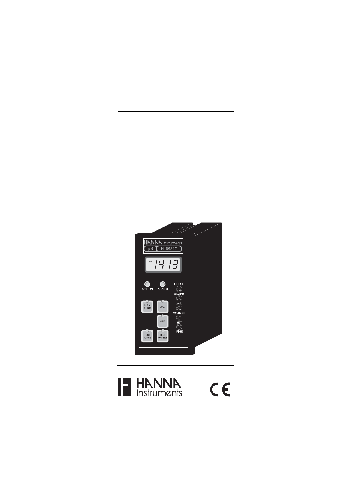
HI 8931A/B/C/D
HI 8936A/B/C/D
HI 8936AL/BL/CL/DL
HI 943500A/B/C/D
Conductivity
Process Instrumentation
These Instruments are in Compliance with the CE Directives
Page 2
Dear Customer,
Thank you for choosing a Hanna Instruments Product.
Please read this instruction manual carefully before using the
instrument.
This manual will provide you with all the necessary information for
correct use of the instruments, as well as a precise idea of thier
versatility in a wide range of applications.
These instruments are in compliance with the directives.
TABLE OF CONTENTS
Preliminary Examination ............................................................ 3
General Description .................................................................... 3
Functional Description HI8931/HI943500 ................................... 5
Functional Description HI8936 .................................................... 9
Conductivity Probes .................................................................. 12
Specifications HI8931 & HI943500 .......................................... 14
Specifications HI8936 .............................................................. 15
Connections .............................................................................. 16
Operational Guide ................................................................... 24
Calibration Procedure of
HI8931 & HI8936 with HI7635.............................................. 30
Calibration Procedure of
HI8931 & HI8936 with HI7638.............................................. 34
Calibration Procedure of
HI943500 with HI7638 .......................................................... 38
Conductivity Versus
Temperature Chart................................................................... 41
Diagnostic Tests ........................................................................ 42
Installation Examples ............................................................... 44
Probe Maintenance and Cleaning ............................................ 46
Accessories ................................................................................ 47
Warranty................................................................................. 50
CE Declaration of Conformity ..................................................... 51
2
Page 3
PRELIMINARY EXAMINATION
Remove the instrument from the packing material and examine it
carefully to make sure that no damage has occurred during shipping.
If there is any noticeable damage, notify your Dealer.
Note: Save all packing materials until you are sure that the
instrument functions correctly. All defective items must be
returned in the original packing materials together with
the supplied accessories.
GENERAL DESCRIPTION
The HI 8931 and HI 943500 are panel mounted conductivity meters
and controllers designed for simplicity of use in a wide range of
industrial process applications.
The instruments are designed with a standard DIN panel mount with
membrane keypads on the front, a large LCD and with autodiagnostic functions.
Probes, power supply, contacts and recorders are connected on the
rear panel through screw terminals.
Using HI 8931 in conjunction with a 4-20 mA output transmitter
HI 8936 series (or HI 8936L series, with LCD display) will assure you
of a strong, interference-free signal at distances up to 300 meters
(1000').
For in-line applications the probe should be HI 7635 and for tanks
HI 7638 with external threads. These probes with built-in NTC sensor,
provide temperature compensated conductivity measurements. The
probe cable length is 3 meters (10').
HI 943500 features a direct connection up to 20 m (67'), without
intermediate amplifiers, to the conductivity probe HI 7638 with 7-pin
DIN connector and automatic temperature compensation.
3
Page 4
Four models with different measurement ranges are available to suit
individual applications:
HI8931A / HI 943500A
HI8936A / HI 8936AL
from 0.0 to 199.9 mS/cm
HI8931B / HI 943500B
HI8936B / HI 8936BL
from 0.00 to 19.99 mS/cm
HI 8931C / HI 943500C
HI8936C / HI 8936CL
from 0 to 1999 µS/cm
HI 8931D / HI 943500D
HI8936D / HI 8936DL
from 0.0 to 199.9 µS/cm
Other features include: recorder output in 0 to 20 mA or 4 to 20 mA
configuration; LED indicators (for HI 8931 and HI 943500) which
identify whether the controller is in operation mode or selection mode.
Each instrument is supplied with a plastic front cover and two
mounting brackets. Power cables are excluded.
Transmitters and conductivity probes are supplied separately.
4
Page 5
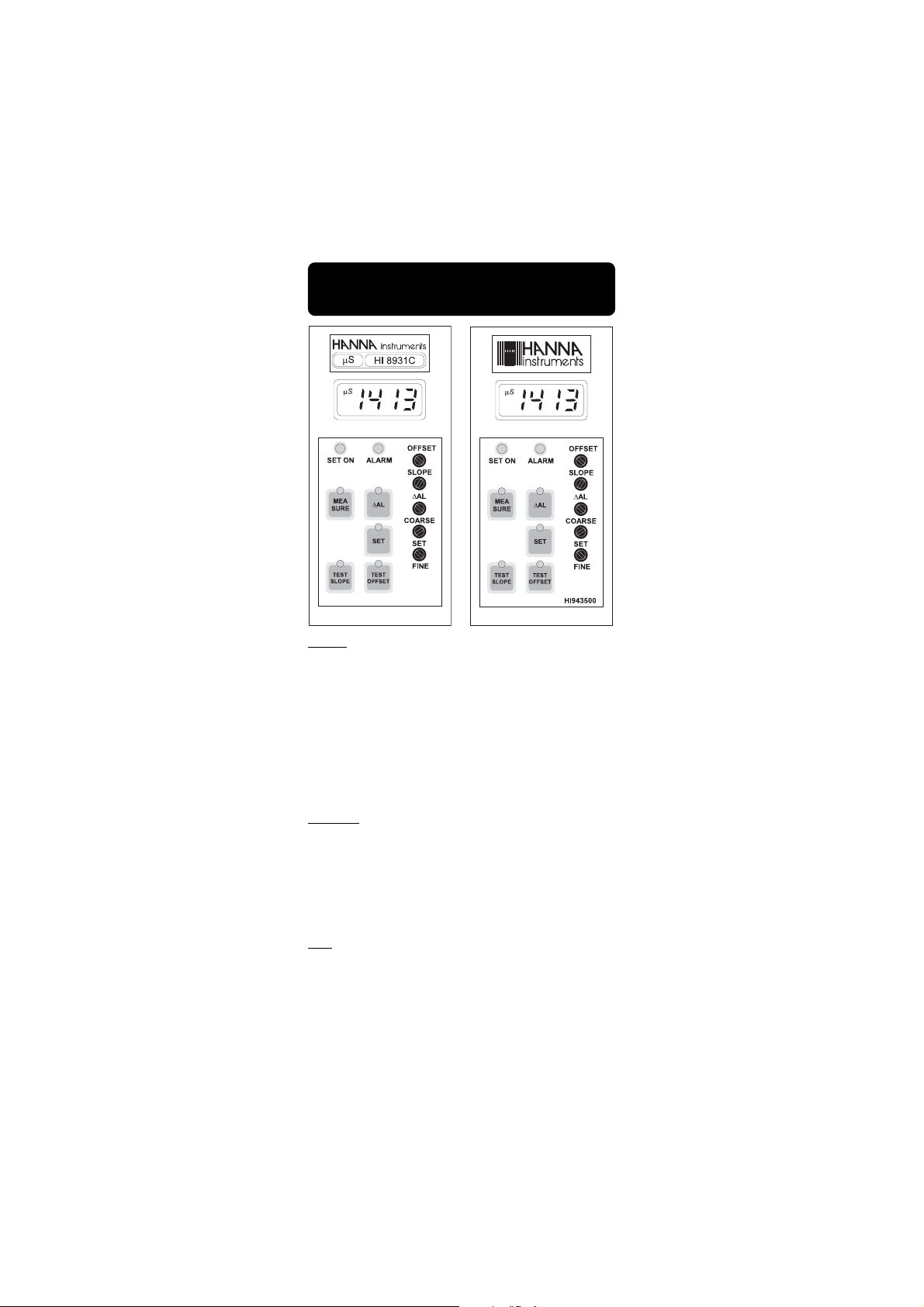
FUNCTIONAL DESCRIPTION
HI 8931 & HI 943500
KEYPAD
MEASURE To read the measurement values and to enable the
diagnostic tests
∆AL To display the set tolerance of the alarm
SET To set the working point
TEST SLOPE Diagnostic function
TEST OFFSET Diagnostic function
When each key is pressed the LED is lighted indicating to the user that the
function is in operation.
TRIMMERS
OFFSET For offset calibration
SLOPE For slope calibration
∆AL To set the alarm tolerance
COARSE To coarsely adjust the set point
SET FINE To finely adjust the set point
LEDS
SET ON To show that the dosage is active
ALARM To show that the controller is in alarm mode.
5
Page 6
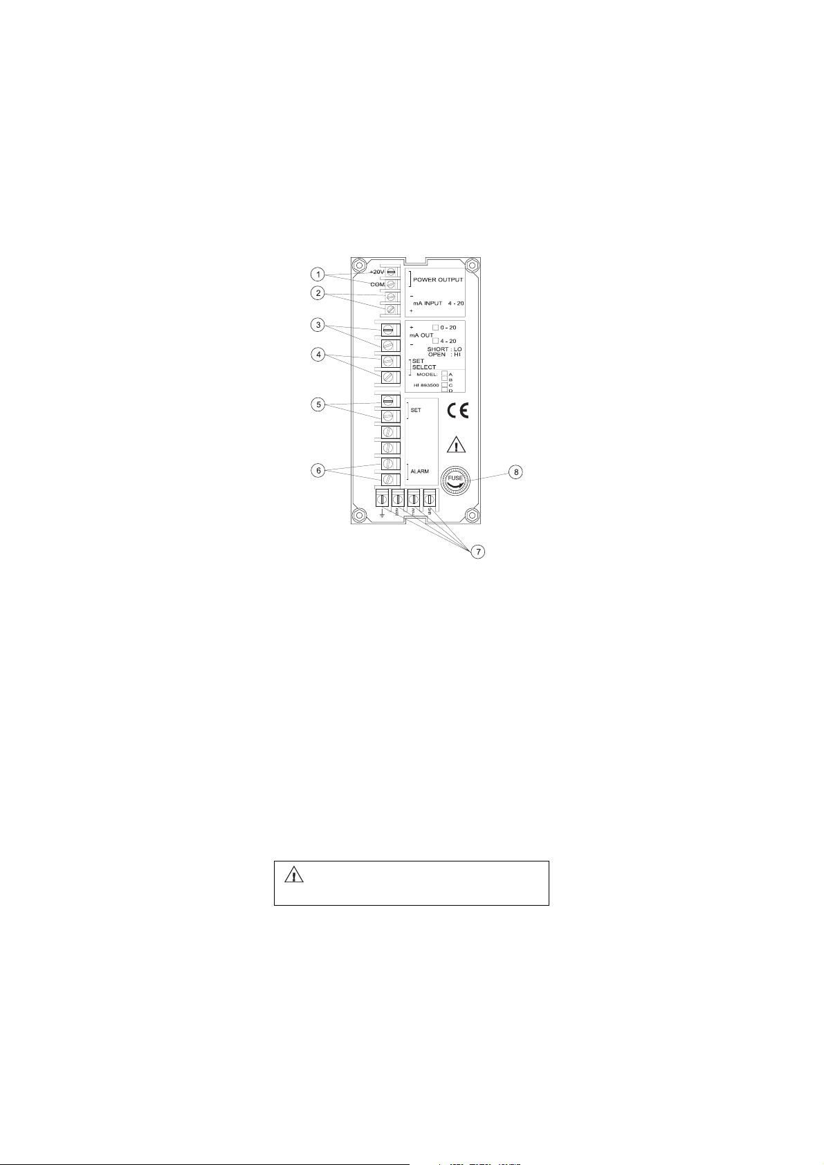
THE REAR PANEL OF HI 8931A/B/C/D
1. Power OUTPUT Terminals (+20V and COM) for connection
to a conductivity transmitter HI8936
2. mA INPUT from a conductivity transmitter
3. mA OUTPUT Terminals for connection to a recorder
4. SET SELECT Terminals for reverse control operation
5. SET Terminals for connection to a dosing pump
6. ALARM Terminals for connection to an external alarm device
7. Power Supply
8. Fuse Holder.
Unplug the instrument from power supply before
the replacement of the fuse.
6
Page 7
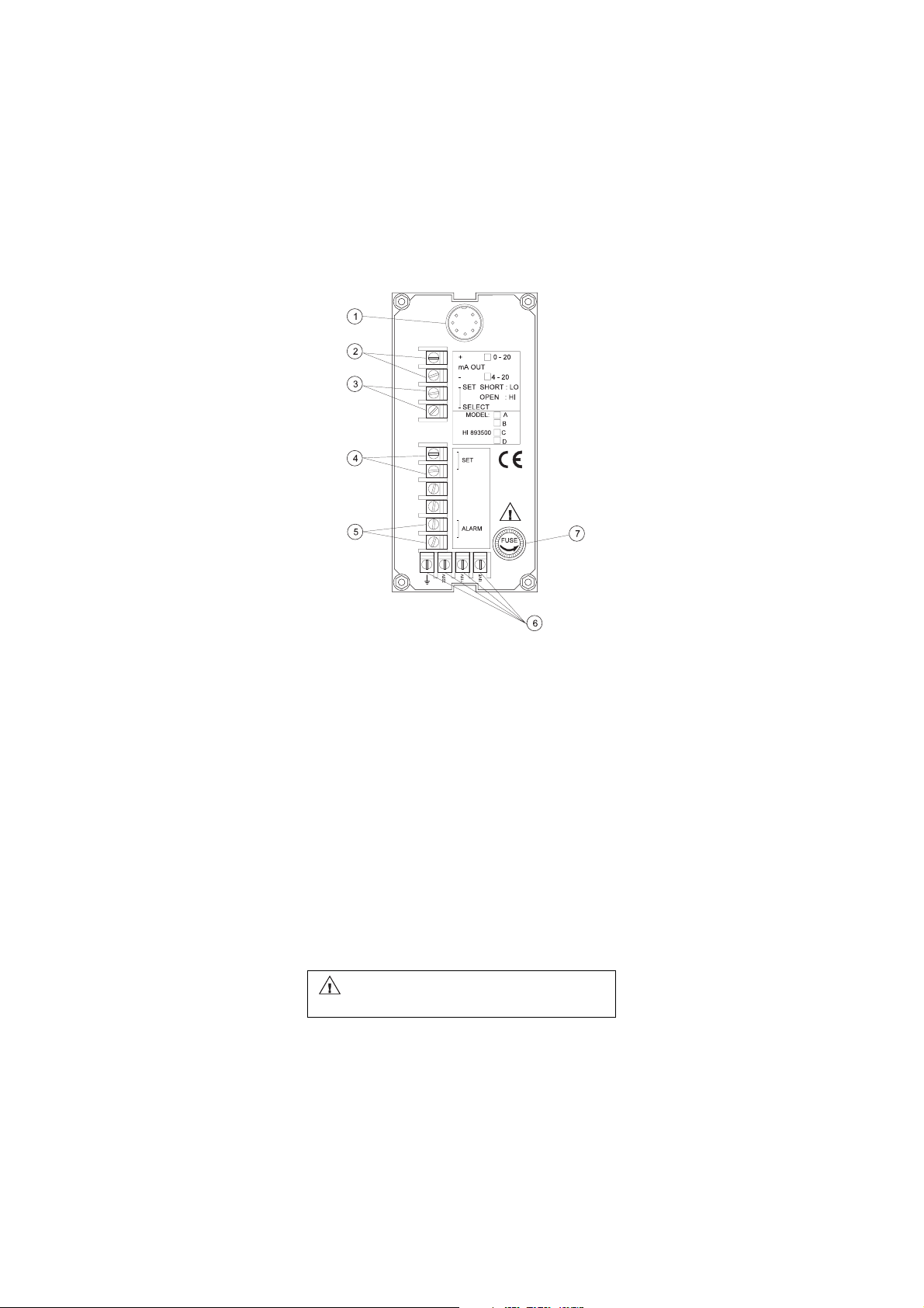
THE REAR PANEL OF HI 943500A/B/C/D
1. Conductivity Probe Connector (7-pin DIN)
2. mA OUTPUT Terminals for connection to a recorder
3. SET SELECT Terminals for reverse control operation
4. SET Terminals for connection to a dosing pump
5. ALARM Terminals for connection to an external alarm device
6. Power Supply
7. Fuse Holder.
Unplug the instrument from power supply before
the replacement of the fuse.
7
Page 8
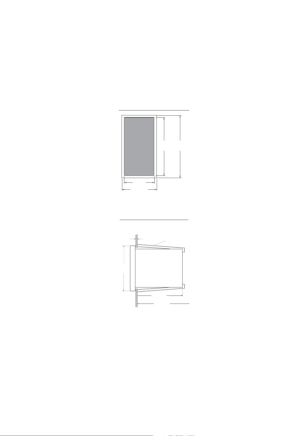
MECHANICAL DIMENSIONS
OF HI 8931 AND HI 943500
Front view of the panel-mounted unit
69mm
2.71"
72mm
2.83"
141mm
5.55"
144mm
5.67"
These dimensions show the cutout size for the installation.
Side view of the panel-mounted unit
144mm
5.67"
0.25/4mm
0.01/0.160"
ADJUSTABLE
LOCATION
BRACKET
135mm
5.31"
190mm MIN
7.50"
Adjustable location brackets (supplied with the meter) allow the indicator
to slide into the cutout and will hold the unit securely in place. 190 mm
(7.50") is the minimum amount of room required to install the indicator
with the cables connected.
8
Page 9
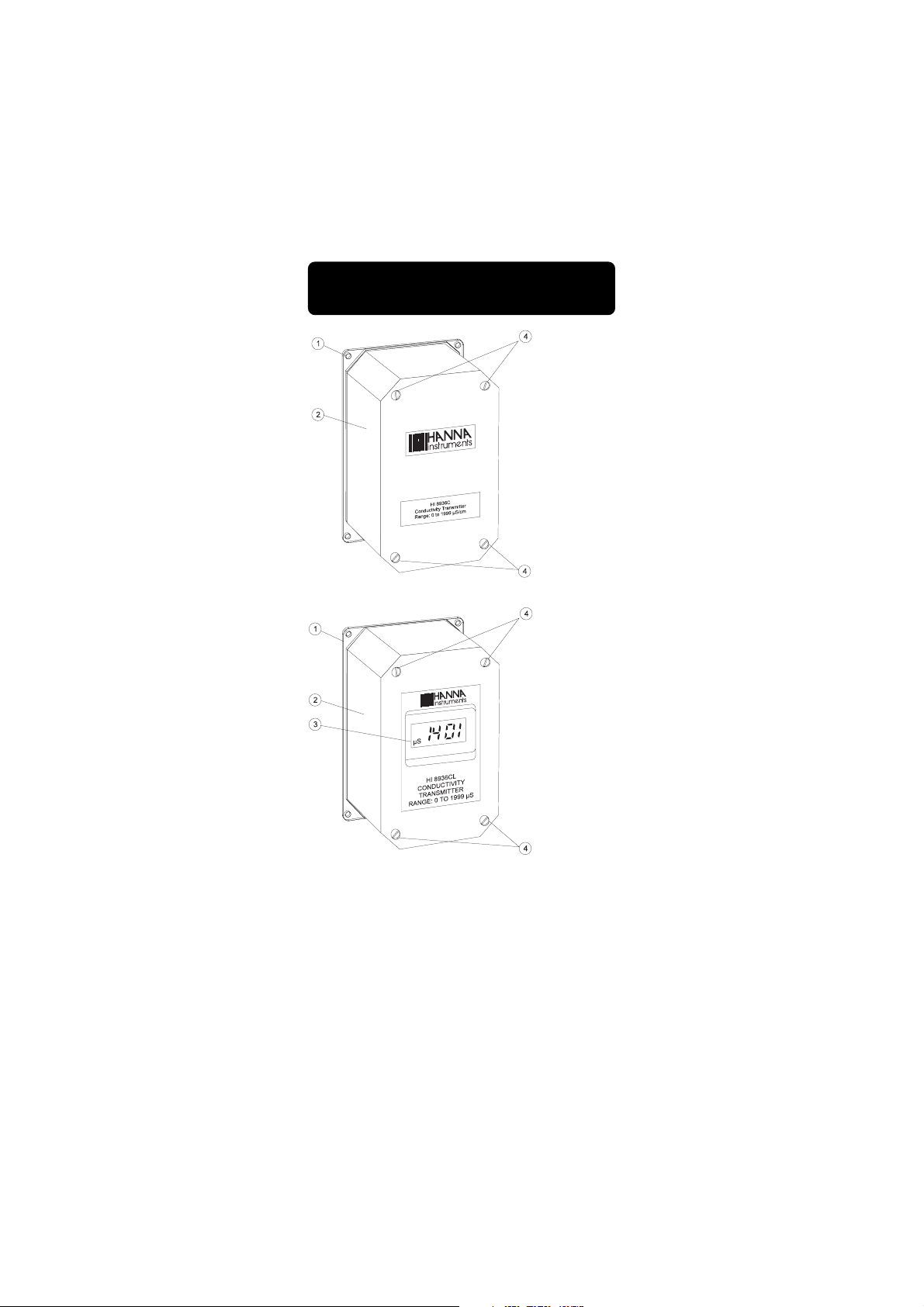
FUNCTIONAL DESCRIPTION
HI 8936
HI8936A
HI8936B
HI8936C
HI8936D
HI8936AL
HI8936BL
HI8936CL
HI8936DL
1. Back Cover
2. Top Plastic Cover
3. LCD Display (for HI8936AL, HI 8936BL, HI8936CL, HI 8936DL
only)
4. Screws for fastening the top cover.
9
Page 10
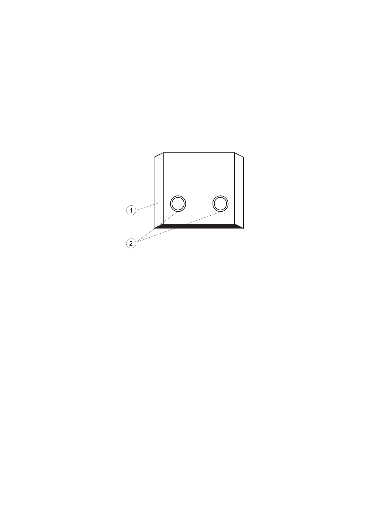
SIDE VIEW
HI 8936A HI8936B HI8936C HI8936D HI 8936AL
HI8936BL HI8936CL HI8936DL
1. Top Plastic Cover
2. Wire cable glands.
10
Page 11

MECHANICAL DIMENSIONS
HI 8936A, HI8936B, HI8936C, HI 8936D
165mm
6.50"
100mm
3.94"
HI 8614
4 x 4.3mm
90mm
3.54"
4 x 0.17"
155mm
6.10"
MECHANICAL DIMENSIONS
HI 8936AL, HI8936BL, HI8936CL, HI 8936DL
110mm
4.33"
90mm
3.54"
24mm
0.94"
45mm
1.77"
4 x 4.3mm
4 x 0.17"
11
58mm
2.28"
165mm
6.50"
155mm
6.10"
126mm
5.00"
HI 8614L
100mm
3.94"
110mm
4.33"
Page 12
CONDUCTIVITY PROBES
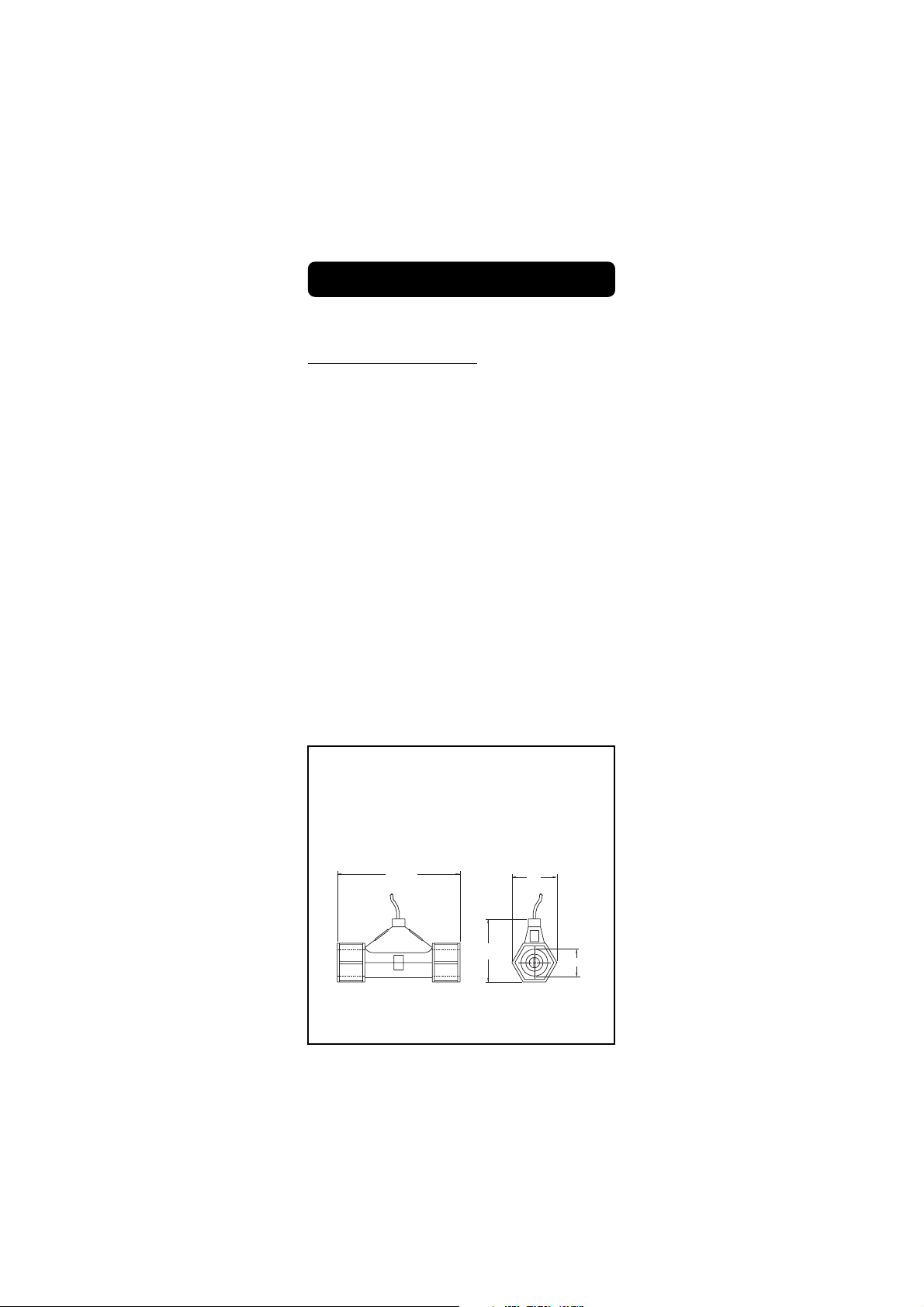
HI 7635 In-line Conductivity Probe
HI 7635 is a one piece, molded conductivity probe with pipe threads
(1" NPT) at both ends.
This allows the probe to attach to an in-line system, and to be used
in conjunction with the HI 8936 conductivity transmitter.
The HI 7635 uses a 4-ring potentiometric measuring method. This
method is highly accurate and requires very little maintenance.
The construction of the housing is rugged, fiber-reinforced polypropy-
lene.
The maximum working pressure of this unit is 5 BAR (72.5 psi).
Do not use in systems where the temperature exceeds 80°C (176°F).
142mm
5.60"
HI7635
12
73mm
2.87"
52mm
2.04"
1" NPT
Page 13
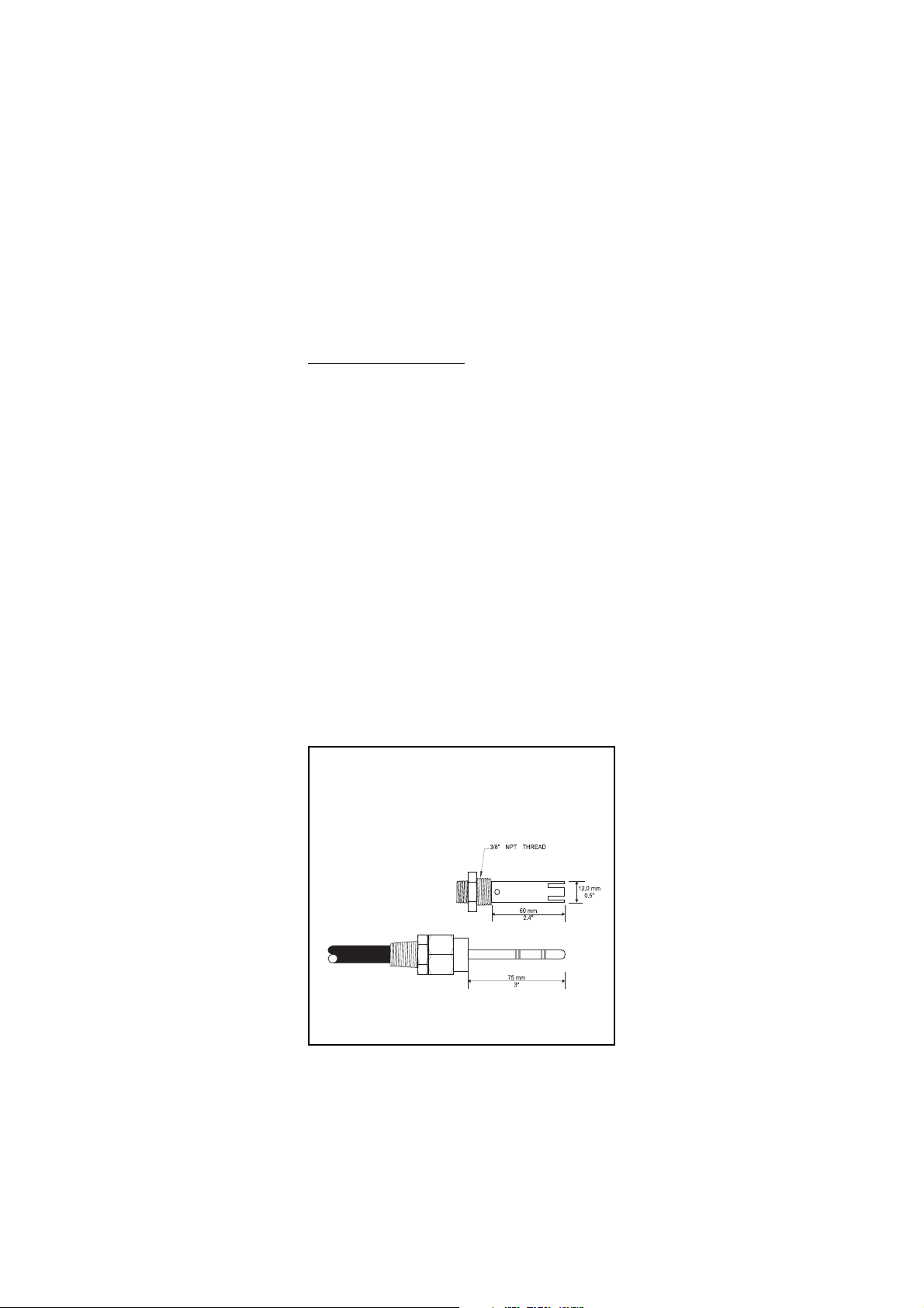
HI7638 Tank Conductivity Probe
HI7638 conductivity probe combines the proven 4-ring potentiometric
method of measuring conductivity with the platinum sensor and
stainless steel external thread.
This method incorporates a series of four platinum rings into the probe
shaft and is highly accurate requiring very little maintenance.
The removable cover is made of Ultem® which resists the harmful
effect of most chemicals and can be unscrewed for quick and simple
maintenance.
This probe can withstand temperatures of up to 120°C (248°F) and
pressure of up to 5 bar (72.5 psi).
This probe is supplied complete with a 7-pin DIN connector.
HI7638
13
Page 14
SPECIFICATIONS HI 8931 & HI 943500
Range
HI8931A - HI943500A
HI8931B - HI943500B
HI8931C - HI943500C
HI8931D - HI943500D
Accuracy
(@20°C/68°F)
Typical EMC
Deviation
4-20mA INPUT from
Transmitter
HI8931A
HI8931B
HI8931C
HI8931D
HI943500
Conductivity Probe
Calibration
Temp. Compensation
HI8931
HI943500
Readout
Recorder Output
1 Set Point Relay &
1 Alarm Relay
Power Supply
Panel Cutout
Environment
Weight
Enclosure
0.0 to 199.9 mS/cm
0.00 to 19.99 mS/cm
0 to 1999 µS/cm
0.0 to 199.9 µS/cm
±2% of Full Scale
excluding probe error
±2.5% of Full Scale
±0.4 mA
HI8936 A or AL (not included)
HI8936 B or BL (not included)
HI8936 C or CL (not included)
HI8936 D or DL (not included)
------
HI7635 for in-line applications or
HI7638 for tank (not included)
Manual 2-point through offset and
slope trimmers
See transmitter HI8936
Automatic from 0 to 60°C with ß=2%
4-digit LCD plus graphic symbols
4 to 20 mA (isolated)
Isolated, 2A, Max. 240V, resistive
load, 1,000,000 strokes
110/115V or 220/240V
(user selectable); 50/60 Hz
141 x 69 mm (5.6 x 2.7")
-10 to 50°C (14 to 122°F)
1 Kg (2.2 lb.)
DIN 43 700 144x72 mm (5.7x2.8") in
black anodized aluminum. Front and
back with shockproof ABS plastic and a
transparent cover.
14
Page 15
SPECIFICATIONS HI 8936 & HI 8936L
Range
HI8936A & AL
HI8936B & BL
HI8936C & CL
HI8936D & DL
Accuracy
(@20°C/68°F)
Typical EMC
Deviation
Conductivity Probe
Calibration
Temperature
Compensation
Output
Power Supply
HI8936A/B/C/D
HI8936AL/BL/CL/DL
Protection
Environment
Dimensions
Weight
0.0 to 199.9 mS/cm
0.00 to 19.99 mS/cm
0 to 1999 µS/cm
0.0 to 199.9 µS/cm
±2% of Full Scale
excluding probe error
±2% of Full Scale
±0.4 mA
HI7635 for in-line applications or
HI7638 for tank (not included)
Manual 2-point through Offset and
Slope trimmers
Fixed or automatic
from 0 to 50°C (32 to 122°F)
with ß=2%
4 to 20 mA not-isolated
Max. 500 ohm
12 to 30 VDC
17 to 36 VDC
0 to 50°C (32 to 122°F)
95% RH max
165 x 110 x 90 mm (LxWxH)
(6.5 x 4.3 x 3.5")
1 Kg (2.2 lb.)
IP 65
15
Page 16
CONNECTIONS
REAR CONNECTIONS FOR HI 8931
• Power Connection Terminals
4-screw-terminal-strip for connection
to a 3-wire power cable according to
the indicated voltage (115 or 230V).
• IN/OUT Transmitter
2 wires of the 4-core signal cable
from the conductivity transmitter
(HI8936) have to be connected to
the mA input terminals and the
other 2 wires to the "+20V" and
"COM" while paying careful attention to the polarity.
+20V supply is the regulated DC supply required for the
operation of the external Conductivity Transmitter HI8936.
• Set Contacts
Dosing pumps or other control equipment may be connected to the "SET"
(Max. 2A, 240V) terminals. These
contacts act only as a "dry" switch
allowing electrical continuity, not as
a power supply.
16
Page 17

• Set Select
These contacts permit the activation
of a Set Contact relay when the
measured value is lower (connected
terminals) or higher (open terminals) than the user's set value. See
also page 27.
• +4-20 mA
These are the output terminals for connection to a recorder or other
control equipment.
The output current varies from 4 to 20 mA and is proportional to
the measured conductivity value.
• Alarm Contacts
During normal operation these terminals remain closed.
If the measured conductivity level is
not within the tolerance of the set
value, the alarm contact is open.
These contacts act only as a switch.
See also page 28.
17
Page 18

TERMINAL BOARD CONNECTIONS FOR H8936
• Remove the 4 screws and the top cover of the HI 8936 conductivity
transmitter to obtain access to the terminal board connections.
• HI8936 used in conjunction with HI8931 controller
Use a PVC insulated 4-core cable to connect the transmitter to the
18
Page 19

HI8931 conductivity controller (see
also page 24).
The 4-core cable has to be connected to the transmitter according
to the label instructions on the 4terminal strip.
The regulated D.C. supply required for the proper operation of the
transmitter is "+20V", labeled "+20V" and "COM". The current
(mA) output terminals are labeled "4-20 mA" and "COM".
The transmitter is protected against inversion of supply voltage.
• HI8936 used in conjunction with
an external power supply
Use 2 PVC insulated 2-core cables.
Connect a +20V DC power supply
directly to the terminals labeled
"+20V" and "COM", paying careful attention to polarity (see also
page 24) or if necessary in series with the receiving device.
The regulated D.C. supply required for the proper functioning of
the circuit is marked "+20V" and "COM", and the transmitter
current output is indicated "4-20 mA" and "COM".
The transmitter is protected against inversion of supply voltage.
Max. current required: 40 mA.
• Use of an amplifier
The maximum permissible distance between the power supply unit
and the amplifier is 300 m (1000'). It is not necessary to use a
shielded cable.
19
Page 20

• Probe Connection
The conductivity probe is supplied
with a 3 m (10'), 6 core cable. The
cable is to be connected to the
terminals provided (see also page
23 for proper connection scheme of
HI 7635 and HI7638).
20
Page 21

REAR CONNECTIONS FOR HI 943500
• Power Connection Terminals
4-screw-terminal-strip for connection to a 3-wire power cable according to the indicated voltage
(115 or 230V).
• 7-pin DIN connector
socket
For connection to the
HI 7638 conductivity
probe.
• + mA output -
The first and the second
terminals are the output
terminals for connection to
a recorder or other control
equipment. The output current varies from 4 to 20
mA and is proportional to
the measured conductivity
value.
• Set Select
These contacts permit the activation of the Set Contact relay when
the measured value is lower (connected terminals) or higher (open
terminals) than the user's set value. See also page 27.
21
Page 22

• Set
Dosing pumps or other control equipment may be connected to the
"SET" (Max. 2A, 240V) terminals. These contacts act only as a
"dry" switch allowing electrical continuity, not as a power supply.
• Alarm Contacts
During normal operation these terminals remain closed.
If the measured conductivity level
is not within the tolerance of the
set value, the alarm contact is
open. These contacts act only as a
switch. See also page 28.
22
Page 23

CONDUCTIVITY PROBE CONNECTIONS
The connections for HI 7635
are color coded for easy installation and are as follows:
HI 7635 cable HI8936 transmitter
Black or Grey NTC
Red or Pink SENSOR
Brown or Orange probe pin 1
Blue probe pin 2
White probe pin 3
Green or Yellow probe pin 4
The connections for HI 7638 are
as follows:
HI 7638 HI8936 transmitter
#1 probe pin 1
#2 probe pin 2
#3 probe pin 3
#4 probe pin 4
#5 NTC
#6 SENSOR
Note: NTC and SENSOR are equivalent and are both labeled
SENSOR on the HI8936 conductivity transmitter.
23
connector
inside view
Page 24

OPERATIONAL GUIDE
INITIAL PREPARATION & INSTALLATION:
Material needed:
• a 3-wire power cable (for connection of HI 8931/HI943500 to
the mains)
• a PVC insulated 4-core cable (as connection cable between
HI8931 and HI8936)
• rubber seals and a pipe sealant (for installation of HI7635)
FOR HI 8931 AND HI8936 ONLY
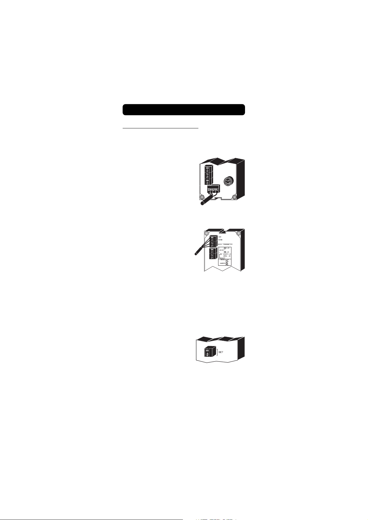
• Remove the 4 screws and the top
of the HI8936 Process Conductivity
transmitter.
• Connect the 2 wires connected to
the 4-20 mA and COM terminals of the 4-core signal cable
from the conductivity transmitter
HI8936 to the terminals marked
mA input paying careful attention
to polarity. Connect the other 2
wires to the +20V and COM terminals while paying careful attention to polarity.
• Connect the 3-wire power cable to
the 4-screw terminal strip according to the voltage level as indicated and pay particular attention to the correct live, earth and
neutral terminal connections.
24
Page 25

• The HI 8936 transmitter may be wallmounted at any convenient location close
to the measurement site. To minimize
thermal drifts due to extreme temperature
fluctuations, particularly if the measurement is conducted outdoors, it is recommended that the transmitter is protected
in a casing.
• For the installation of the HI 7635 conductivity probe, it is
necessary to use rubber seals between the probe and the pipe or
elbow joints. A pipe sealant is also recommended to ensure a leak
free joint. When screwing on the joints, take care not to overtighten as excessive pressures can cause the probe to be damaged.
• The conductivity probe HI 7635 is supplied with a 3m (10') length of cable.
The six core cable from the probe is
connected to the HI8936 process conductivity transmitter as shown. The
connections are color coded for an easy
installation. See page 23 for the proper
connection scheme.
25
Page 26

• It is recommended that the HI7635 is installed vertically. This is
to ensure that trapped air bubbles or turbulent flows cause
minimal interference to the measurement system. The maximum
working pressure of this unit is 5 BAR (72.5 psi).
CAUTION: do not use in systems where temperature exceeds 80°C
(176°F).
• The HI7638 process conductivity probe is also
supplied with a 3m (10') length cable. The
six core cable from this probe is connected to
the HI 8936 process conductivity transmitter
as shown.
The 7-pin DIN connector has to be removed when this probe is
used in conjunction with HI8936 transmitter. See page 23 for the
proper connection scheme.
FOR HI 943500 ONLY
Ensure that the HI7638 conductivity probe is connected to
the meter securely by aligning
the pins with the socket, pushing the plug in and tightening
the threaded ring.
26
Page 27

OPERATING INFORMATION
The various parameters are set through the front panel keys and
trimmers.
When each key is pressed the corresponding LED is lit, indicating that
the function is operational.
Make sure that the conductivity meter, transmitter and probe are
calibrated before using the instrument for measurements (see page
30 & 34 for HI8931 & HI8936 and page 38 for HI 943500).
SET POINT
To set the working point of the controller, press the SET key. The
display will indicate the set value.
Use a small screwdriver to adjust
the trimmers COARSE and FINE
until the desired set value is
displayed.
Above set-point control operation
Leave the SET SELECT/COM connectors open.
The set contacts relay will close if the measured value is higher than the set-point
value and the SET ON LED will be lit.
27
COM
SET
SELECT
Page 28

Below set-point control operation
Short the SET SELECT/COM connectors with
a jumper wire. The set contact relay will
close if the measured value is lower than
COM
SET
SELECT
the set-point value and the SET ON LED
will be lit.
ALARM
Press the ∆AL key and the display will show the set tolerance for the
alarm.
Use a small screwdriver to adjust
the trimmer ∆AL until the desired tolerance is displayed.
Example: If the set value is 200
µS/cm and a ∆Alarm of 50 µS/
cm is set, an alarm is activated
every time the measured value
is higher than 250 µS/cm or
lower than 150 µS/cm.
28
Page 29

When the alarm is active the ALARM LED is lit.
The alarm contacts of HI 8931 and HI 943500 remain closed during
normal operation. If the measured conductivity level is not within the
tolerance of the set value, the alarm contact will be open.
TAKING MEASUREMENTS WITH HI8931 AND HI 943500
After setting the working point and alarm value, press the MEASURE key.
The actual conductivity value of the test solution will be displayed.
TAKING MEASUREMENTS WITH HI8936AL, HI8936BL,
HI 8936CL, HI8936DL
The conductivity transmitters with LCD will
always display the measurement value
when connected to the HI8931 controllers
or a power supply.
29
Page 30

CALIBRATION PROCEDURE OF
HI8931 & HI8936 WITH HI7635
Material needed
• HI 7635 conductivity probe
• HI 8931 conductivity controller
• HI 8936 conductivity transmitter
• A 20 mA f.s. ammeter (for transmitters without LCD)
• A reference conductivity meter with automatic temperature compensation accurately calibrated (e.g. HI8733).
PROCEDURE
• Connect the HI7635 probe to the HI8936 transmitter (see page
23).
• Connect the HI8936 transmitter to the HI 8931 controller (see
page 24).
• Connect the HI8931 controller to the mains (see page 24).
Before proceeding with the calibration,
make sure that the meter is in measurement mode (MEASURE LED will be lit)
and not in set mode.
• Connect the ammeter to the HI8936 transmitter to monitor the
signal current (see the following picture).
MEA
SURE
30
Page 31

• Ensure that there is no solution inside the HI7635 conductivity
probe (dry probe).
• When the power is on, the ammeter should read "4.0 mA". The
HI8936L transmitter with LCD should display "0".
• If not, adjust the OFFSET trimmer
of the HI8936 transmitter to obtain "4 mA" or "0" on the
HI8936L.
• The HI 8931 controller should display "0" value.
• If not, adjust the OFFSET trimmer
of HI8931 to display a zero reading.
• Switch the flow on and allow the
sample solution to flow through
the HI 7635 conductivity probe.
Collect a sample of this solution in
a beaker.
• Measure the conductivity of the
solution with the HI8733 portable conductivity meter with ATC.
The value obtained will be used
for the transmitter and controller
calibration.
31
µS
°C
HI 8733
199.9
µS
19.99
mS
0
0.5
TEMPERATURE COEFFICIENT
s
ins
rum n
ON
OFF
1999
µS
199.9
mS
2.5
2
1.51
Page 32

• The reading will be converted to mA by the following formula:
mA = K (measured value x 16/2000) + 4
K = conversion factor depending on the model
Model Conversion factor K
HI 8936A & AL 10
HI 8936B & BL 100
HI8936C & CL 1
HI8936D & DL 10
For example, using a HI8936A, if the measured value is 123.4
mS, then
output current = 10 x (123.4 x 16/2000) + 4
= 13.9 mA
Adjust the SLOPE trimmer of the
HI8936 transmitter to read "13.9
mA" on the ammeter or the reading
displayed by the HI8733 conduc-
tivity meter on the HI8936L dis-
play. E.g. "123.4 mS".
• Adjust the SLOPE trimmer of the HI 8931 controller until the
controller reading is the same as the reading displayed by the
HI8733 conductivity meter. E.g. "123.4 mS".
32
Page 33

• The calibration is now complete and the instrument is ready for
use. All subsequent measurements will now be compensated to
25°C (77°F).
• If the instrument will not calibrate refer to the Probe Maintenance
and Cleaning section (see page 46).
• If the HI8936 transmitter is not used in conjunction with the
HI8931 controller, connect the transmitter to an external power
supply (see page 19). Connect the transmitter to the HI7635
conductivity probe (see page 23) and to an ammeter (see page
19).
The calibration of the transmitters with LCD (HI8936AL, HI 8936BL,
HI8936CL, HI 8936DL) does not require an ammeter.
Follow the above calibration procedure performing the operations
referred to the HI8936 transmitter only.
33
Page 34

CALIBRATION PROCEDURE OF
HI8931 & HI8936 WITH HI7638
Material needed
• HI 7638 conductivity probe
• HI 8931 conductivity controller
• HI 8936 conductivity transmitter
• An ammeter (for transmitters without LCD)
• Calibration solutions, according to the different models:
HI7034 80 mS/cm @25°C
for HI8931A, HI8936A & AL
HI7030 12.88 mS/cm @25°C
for HI8931B, HI8936B & BL
HI7031 1413 µS/cm @25°C
for HI8931C, HI 8936C & CL
HI7033 84 µS/cm @25°C
for HI8931D, HI8936D & DL
PROCEDURE
• Connect the HI 7638 to the HI8936 transmitter (see page 23).
• Connect the HI8936 transmitter to the HI 8931 controller (see
page 24).
• Connect the HI8931 controller to the mains (see page 24).
Before proceeding with the calibration,
make sure that the meter is in measurement mode (MEASURE LED will be lit)
and not in set mode.
• Connect the ammeter to the HI8936 transmitter to monitor the
signal current (see the following picture).
MEA
SURE
34
Page 35

• Leave the HI7638 conductivity probe
in air (dry probe).
• When the power is on, the ammeter should read "4.0 mA" or the
HI8936L transmitter with LCD should display "0".
• If not adjust the OFFSET trimmer
of the HI8936 transmitter to obtain "4 mA" or "0" on the HI8936L.
• The HI8931 controller should display "0" value.
• If not adjust the OFFSET trimmer of
HI8931 to display a zero reading.
35
Page 36

HI 7030
• Pour enough conductivity solution into a
plastic beaker to achieve at least 8 cm
(3¼
(3¼") of depth.
8 cm
")
• Immerse the probe into the beaker with the
conductivity solution. The holes on the sleeve
must be completely submerged in the solution.
• Tap the probe repeatedly on the bottom of the beaker and stir it
to ensure that no air bubbles are trapped inside the sleeve.
• If the temperature of the probe is close to that of the solution the
display of HI 8931 will stabilize quickly and provide a temperature
compensated conductivity measurement. However, allow a few
minutes if there is a temperature difference of 5°C (9°F) or more for
the ATC circuitry to compensate completely.
• For HI 8936
Adjust the SLOPE trimmer of the HI8936 transmitter to read on
the ammeter:
"10.4 mA" using HI7034 and HI8936A/AL
"14.304 mA" using HI7030 and HI8936B/BL
"15.304 mA" using HI7031 and HI8936C/CL
"10.72 mA" using HI7033 and HI8936D/DL
36
Page 37

• FOR HI 8931
When the reading stabilizes, turn the SLOPE trimmer on the front
of the HI8931 until the LCD reading is the same as the calibration
solution at 25°C (77°F), i.e.
"80.0 mS" using HI7034 with HI 8931A
"12.88 mS" using HI7030 with HI 8931B
"1413 µS" using HI7031 with HI 8931C
"84.0 µS" using HI7033 with HI 8931D
• The calibration is now complete and the instrument is ready for
use. All subsequent measurements will now be compensated to
25°C (77°F).
• If the instrument will not calibrate refer to the Probe Maintenance
and Cleaning section (see page 46).
• If the HI8936 transmitter is not used in conjunction with the
HI8931 controller, connect the transmitter to an external power
supply (see page 19). Connect the transmitter to the HI7638
conductivity probe (see page 23) and to an ammeter (see page
19).
The calibration of the transmitters with LCD (HI8936AL, HI 8936BL,
HI8936CL, HI 8936DL) does not require any ammeter.
Follow the above calibration procedure performing the operations
referred to the HI8936 transmitter only.
37
Page 38

CALIBRATION PROCEDURE OF
HI943500 WITH HI7638
Material needed
• HI7638 conductivity probe
• HI943500 conductivity controller
• Calibration solutions, according to the different models:
HI7034 80mS/cm @25°C for HI943500A
HI7030 12.88mS/cm@25°C for HI943500B
HI7031 1413 µS/cm @25°C for HI943500C
HI7033 84 µS/cm @25°C for HI943500D
PROCEDURE
• Ensure that the probe is connected
to the meter securely by aligning the
pins with the socket, pushing the
plug in and tightening the threaded
ring.
• Insert the probe into the sleeve.
• With the conductivity probe in air,
press the MEASURE key to set the
meter to MEASURE mode.
38
Page 39

• Adjust the OFFSET trimmer if the LCD does not show the zero
reading.
HI 7030
• Pour enough conductivity solution into a
beaker to achieve at least 8 cm (3¼") of
depth.
(3¼
")
8 cm
• Immerse the probe into the beaker with the
conductivity solution. The holes on the sleeve
must be completely submerged in the solution.
• Tap the probe repeatedly on the bottom of the beaker and stir it
to ensure that no air bubbles are trapped inside the sleeve.
• If the temperature of the probe is close to that of the solution the
display will stabilize quickly and provide you with a temperature
compensated conductivity measurement.
However, allow a few minutes if there is a temperature difference
of 5°C (9°F) or more for the ATC circuitry to compensate completely.
• When the reading stabilizes, turn the SLOPE trimmer on the front
of the HI943500 until the LCD reading is the same of the
calibration solution at 25°C (77°F), i.e.:
80.0 mS using HI7034 with HI943500A
12.88 mS using HI7030 with HI943500B
1413 µS using HI7031 with HI943500C
84.0 µS using HI7033 with HI943500D
39
Page 40

• The calibration is now complete and the instrument is ready for
use. All subsequent measurements will now be compensated to
25°C (77°F).
• If the instrument will not calibrate refer to the Probe Maintenance
and Cleaning section (see page 46).
40
Page 41

CONDUCTIVITY VERSUS
TEMPERATURE CHART
°C °F HI7030 HI7031 HI 7033 HI7034 HI7035 HI7039
(mS/cm) (mS/cm) (mS/cm) (mS/cm) (mS/cm) (mS/cm)
0 32 7150 776 64 48300 65400 2760
5 41 8220 896 65 53500 74100 3180
10 50 9330 1020 67 59600 83200 3615
15 59 10480 1147 68 65400 92500 4063
16 60.8 10720 1173 70 67200 94400 4155
17 62.6 10950 1199 71 68500 96300 4245
18 64.4 11190 1225 73 69800 98200 4337
19 66.2 11430 1251 74 71300 100200 4429
20 68 11670 1278 76 72400 102100 4523
21 69.8 11910 1305 78 74000 104000 4517
22 71.6 12150 1332 79 75200 105900 4711
23 73.4 12390 1359 81 76500 107900 4805
24 75.2 12640 1386 82 78300 109800 4902
25 77 12880 1413 84 80000 111800 5000
26 78.8 13130 1440 86 81300 113800 5096
27 80.6 13370 1467 87 83000 115700 5190
28 82.4 13620 1494 89 84900 117700 5286
29 84.2 13870 1521 90 86300 119700 5383
30 86 14120 1548 92 88200 121800 5479
31 87.8 14370 1575 94 90000 123900 5575
If you are calibrating a HI8931A or HI 943500A using HI7030
(12.88 mS/cm @25°C) as buffer solution, turn the SLOPE trimmer
to display "12.88 mS", with a reference temperature of 25°C (77°F).
If you prefer a reference temperature of 20°C (68°F), turn the SLOPE
trimmer to display "11.67 mS".
41
Page 42

DIAGNOSTIC TESTS
The HI8931 and HI 943500 controllers are designed with built-in
diagnostic functions to enable the user to check and troubleshoot the
instrument. The checks performed are through the front panel keys and
can be used to isolate the cause of malfunction.
Press the MEASURE key before proceeding the following tests.
A) Test Offset
Press the TEST OFFSET key and the display should indicate the
following values:
HI8931/HI 943500A 0.0 mS ±1.0 mS
HI8931/HI 943500B 0.00 mS ±0.10 mS
HI8931/HI 943500C 000 µS ±100 µS
HI 8931/HI943500D 0.0 µS ±1.0 µS
42
Page 43

B) Test Slope
Press the TEST SLOPE key and the display should indicate the following
values:
HI8931/HI 943500A 100.0 mS ±35.0 mS
HI 8931/HI943500B 10.00 mS ±3.50 mS
HI 8931/HI943500C 1000 µS ±350 µS
HI 8931/HI943500D 100.0 µS ±35.0 µS
Note: The reading obtained by these functions will vary if the OFFSET
and the SLOPE trimmers on the front panel are adjusted.
43
Page 44

INSTALLATION EXAMPLES
Some typical installation setups are depicted in the following examples:
Example #1
Example #2
44
Page 45

Example #3
Example #4
Example #5
45
Page 46

PROBE MAINTENANCE & CLEANING
The probe can be compensated for normal contamination by a process of
re-calibration. However, it is recommended that the process conductivity
probe be removed from the system regularly for maintenance.
For HI7635 only: Deposits on the conductivity probe can be removed by
immersing the probe in 0.1 N Hydrochloric acid for about 30 minutes.
Heavier deposits may demand longer immersion periods. Clean the
electrode thoroughly with water prior to the reinstallation. On reinstalling,
check the seals carefully to ensure that a leak connection is obtained.
For HI 7638 only: Rinse the probe with tap water. If a more thorough
cleaning is desired, unscrew the Ultem sleeve and clean the sensors with
a nonabrasive cloth or alcohol.
After cleaning the probe, re-calibrate the instrument. However, if the
instrument will not re-calibrate with the clean probe, you must replace the
probe.
Note: Always re-calibrate the meter when attaching a new probe.
46
Page 47

ACCESSORIES
CONDUCTIVITY BUFFER SOLUTIONS
HI 7030L 12880 µS/cm (µmho/cm) @25°C (77°F), 460 mL
HI 7030M 12880 µS/cm (µmho/cm) @25°C (77°F), 230 mL
HI 7031L 1413 µS/cm (µmho/cm) @25°C (77°F), 460 mL
HI 7031M 1413 µS/cm (µmho/cm) @25°C (77°F), 230 mL
HI 7033L 84 µS/cm (µmho/cm) @25°C (77°F), 460 mL
HI 7033M 84 µS/cm (µmho/cm) @25°C (77°F), 230 mL
HI 7034L 80000 µS/cm (µmho/cm) @25°C (77°F), 460 mL
HI 7034M 80000 µS/cm (µmho/cm) @25°C (77°F), 230 mL
HI 7035L 111800 µS/cm (µmho/cm) @25°C (77°F), 460 mL
HI 7035M 111800 µS/cm (µmho/cm) @25°C (77°F), 230 mL
HI 7039L 5000 µS/cm (µmho/cm) @25°C (77°F), 460 mL
HI 7039M 5000 µS/cm (µmho/cm) @25°C (77°F), 230 mL
47
Page 48

CONDUCTIVITY PROBES
HI7635 In-line conductivity probe, 3 m (10') cable
(for HI 8936 only)
142mm
5.60"
73mm
2.87"
52mm
2.04"
1" NPT
HI7638 Tank conductivity probe, 3 m (10') cable
(for HI8936 or HI 943500)
48
Page 49

OTHER ACCESSORIES
HI 731326 Small calibration screwdrivers (20 pcs)
HI 779/P 6-wire cable (100 m/330' roll)
HI8733 Portable conductivity meter with automatic
temperature compensation
49
Page 50

WARRANTY
All Hanna Instruments meters are warranted for two years against
defects in workmanship and materials when used for their intended
purpose and maintained according to instructions.
The probes are warranted for a period of six months.
This warranty is limited to repair or replacement free of charge.
Damages due to accident, misuse, tampering or lack of prescribed
maintenance are not covered.
If service is required, contact the dealer from whom you purchased the
instrument. If under warranty, report the model number, date of
purchase, serial number and the nature of the failure. If the repair is not
covered by the warranty, you will be notified of the charges incurred. If
the instrument is to be returned to Hanna Instruments, first obtain a
Returned Goods Authorization Number from the Customer Service department and then send it with shipment costs prepaid. When shipping any
instrument, make sure it is properly packaged for complete protection.
All rights are reserved. Reproduction in whole or in part is prohibited
without the written consent of the copyright owner.
Hanna Instruments reserves the right to modify the design,
construction and appearance of its products without advance
notice.
50
Page 51

CE DECLARATION OF CONFORMITY
Recommendations for Users
Before using these products, make sure that they are entirely suitable for the
environment in which they are used.
Operation of these instruments in residential area could cause unacceptable interferences to radio and TV equipments, requiring the operator to take all necessary steps
to correct interferences.
The trimmers are sensitive to electrostatic discharges. It is recommended to use antistatic screwdrivers.
Unplug the instrument from the power supply before replacing the fuse. External cables
to be connected to the rear panel should end with cable lugs.
To maintain the EMC performance of this equipment, use the recommended cables
mentioned on this instruction manual.
Any variation introduced by the user to the supplied equipment may degrade the
instruments' EMC performance.
To avoid electrical shock, do not use these instruments when voltages at the
measurement surface exceed 24VAC or 60VDC.
To avoid damages or burns, do not perform any measurement in microwave ovens.
51
Page 52

05/03
www.hannainst.com
MANCDPRCR4
 Loading...