

Page 1
Instruction Manual
HI 8819 - HI 8820
Bench Conductivity
Meters
HI 8819
O
N
S
tandard C
O
F
F
onductivity at 25
S
ta
ndard
C
O
N
H
D
I 7033
°C
C
TEM
P
onductivity
H
I 7031
H
90µS
I 7030
H
I 7034
12,880µS
80,000µS
199.9
1413µS
µS
1999
µS
19.99
mS
99.9
mS
TEM
PERA
TURE
HI 8820
O
N
S
tandard C
O
FF
o
nductivity at 25
S
tandard
H
I 70
°C
C
ondu
33
ctivity
H
I 7
031
9
0µS
H
I 7030
H
I 7
034
80,000µS
12,880µS
1
9
9
14
.
9
13
µS
µS
1
µS
1
9
.
9
9
m
S
9
9
.9
m
S
C
http://www.hannainst.com
9
9
9
1
1
.5
0
.5
2
0
2
.5
TE
M
P
E
R
A
O
T
U
E
R
FF
E
IC
IE
N
T
Compliance with the CE Directives
These Instruments are in
Page 2
Dear Customer,
Thank you for choosing a Hanna Instruments Product.
Please read this instruction manual carefully before using the instru-
ment.
This manual will provide you with all the necessary information for the
correct use of the instrument, as well as a precise idea of its versatility
in a wide range of applications.
These instruments are in compliance with CSA, UL and (EN
50081-1 and EN 50082-1) directives.
TABLE OF CONTENTSTABLE OF CONTENTS
TABLE OF CONTENTS
TABLE OF CONTENTSTABLE OF CONTENTS
PRELIMINARY EXAMINATION ................................................................ 3
GENERAL DESCRIPTION ........................................................................ 3
KEYBOARD AND REAR PANEL ............................................................... 4
SPECIFICATIONS .................................................................................. 5
CONDUCTIVITY MEASUREMENTS ........................................................... 6
CALIBRATION ....................................................................................... 8
CONDUCTIVITY VS. TEMPERATURE CHART ........................................... 12
TEMPERATURE COMPENSATION .......................................................... 13
DETERMINATION OF THE TEMPERATURE
COEFFICIENT OF A SOLUTION (FOR HI8820 ONLY) .............................. 14
PROBE MAINTENANCE ....................................................................... 15
ACCESSORIES .................................................................................... 16
WARRANTY ........................................................................................ 18
CE DECLARATION OF CONFORMITY...................................................... 19
ISO 9000 Certified
Company since 1992
2
Page 3
PRELIMINARY EXAMINATIONPRELIMINARY EXAMINATION
PRELIMINARY EXAMINATION
PRELIMINARY EXAMINATIONPRELIMINARY EXAMINATION
Remove the instrument from the packing material and examine it to
make sure that no damage has occurred during shipping. If there is
any damage, notify your Dealer.
Each meter comes supplied with a conductivity probe (HI7685 for
HI8819 or HI7687 for HI8820), a voltage adapter, a dust cover and
an instruction manual.
::
Note
: Save all packing material until you are sure that the instrument
::
functions correctly. All defective items must be returned in the
original packing with the supplied accessories.
GENERAL DESCRIPTIONGENERAL DESCRIPTION
GENERAL DESCRIPTION
GENERAL DESCRIPTIONGENERAL DESCRIPTION
HI8819 and HI8820 are digital bench-top multirange conductivity
meters designed for simplicity of use in measuring electrical conductivity in liquids. Four ranges of conductivity measurements are provided
to cover every application from deionized water to brine. The conductivity probe does not require changing or re-calibration when switching
from one range to another.
The probe is made of glass with 4 platinum rings that are corrosion
resistant. It is also suitable for measuring conductivity of liquids in
small sample sizes, and comes with a 1 m (3.3') cable.
The temperature effect can be compensated through a knob on the
front panel of HI8819.
With HI8820, the 4-ring probe has a built-in temperature sensor that
automatically compensates for temperature changes in the liquid
tested. The temperature coefficient can be adjusted from 0 to 2.5%.
3
Page 4
KEYBOARD & REAR PANELKEYBOARD & REAR PANEL
KEYBOARD & REAR PANEL
KEYBOARD & REAR PANELKEYBOARD & REAR PANEL
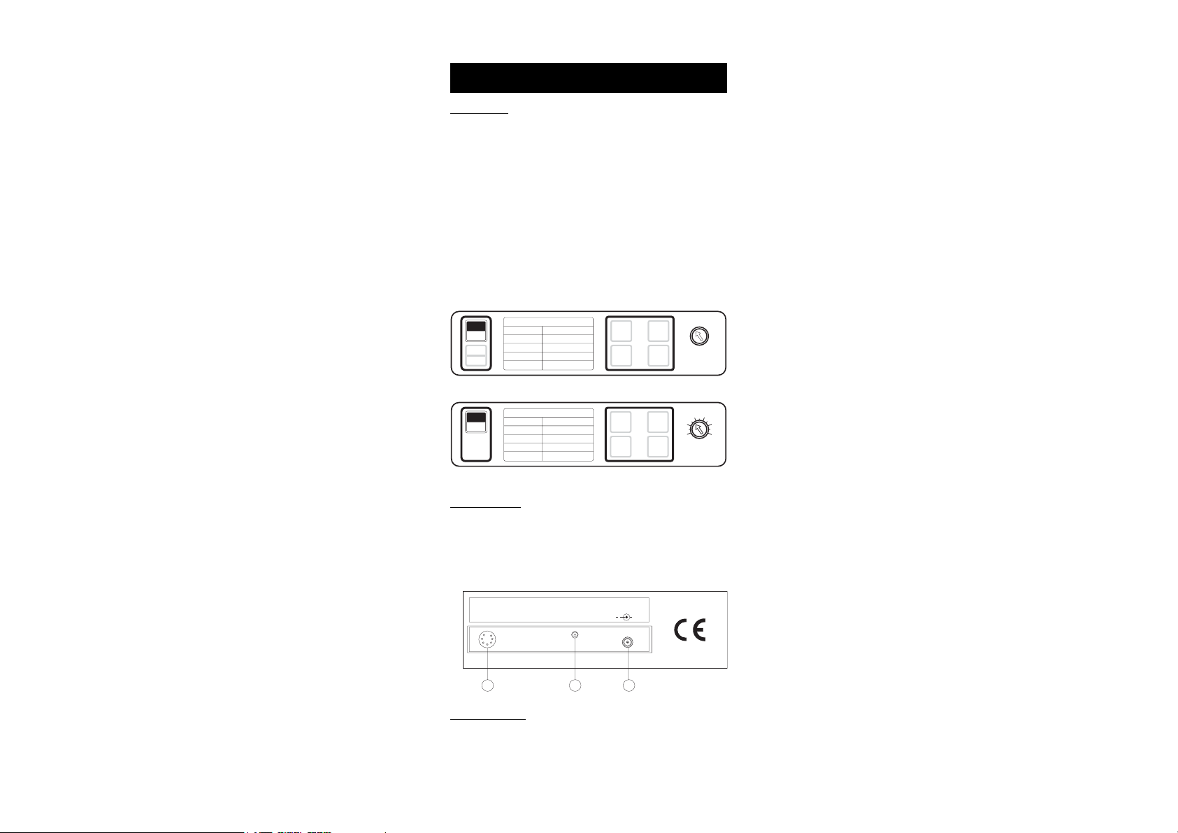
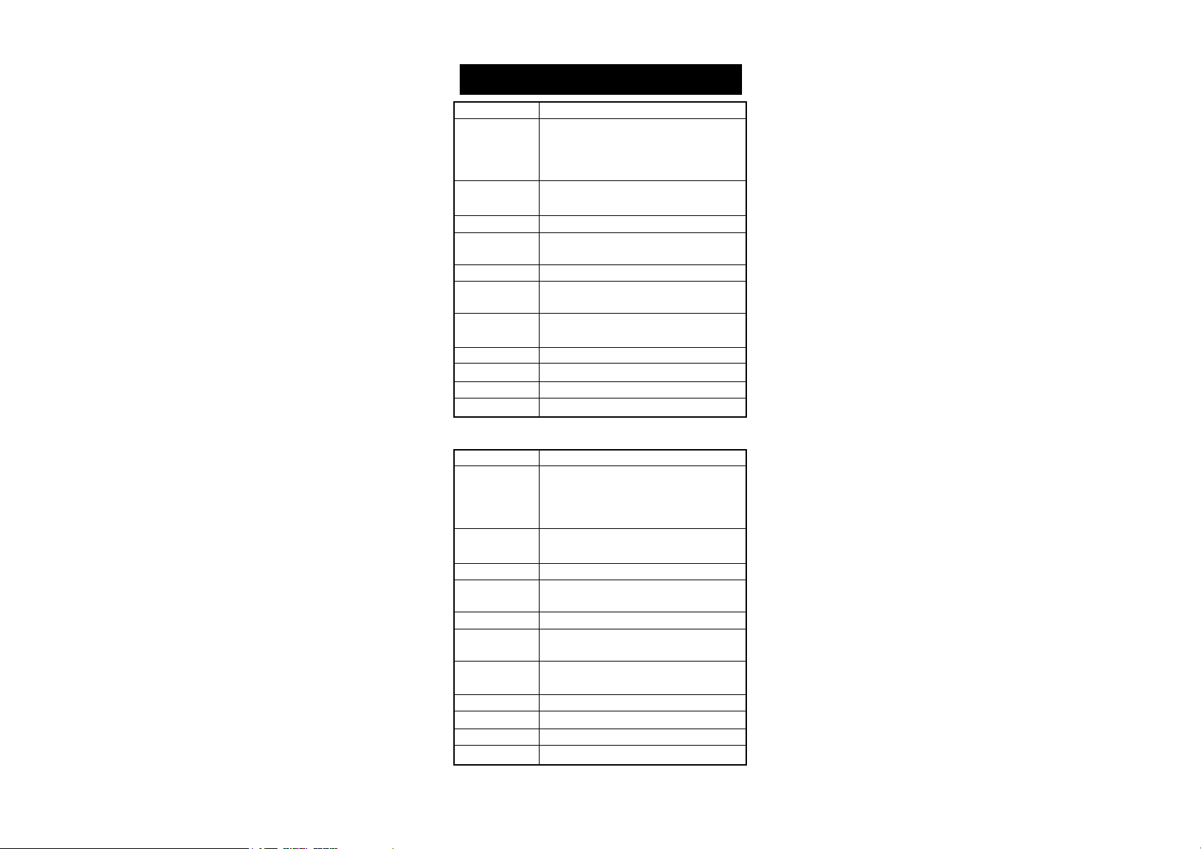
KEYBOARD:
ON/OFF To switch the instrument ON or OFF
COND/TEMP To select the display of conductivity readings or tem-
perature settings for compensation (for HI8819 only)
199.9 µS To select the range 0.0 to 199.9µS/cm
1999 µS To select the range 0 to 1999µS/cm
19.99 mS To select the range 0.00 to 19.99 mS/cm
99.9 mS To select the range 0.0 to 99.9mS/cm
TEMPERATURE Knob: To manually set to the temperature compen-
sation of the reading (for HI8819 only)
TEMPERATURE COEFFICIENT knob: To set the temperature coeffi-
cient from 0% to 2.5% per °C (for HI8820 only).
Standard Conductivity at 25°C
ON
Standard
OFF
COND
TEMP
HI 7033
HI 7031
HI 7030
HI 7034
Keyboard of HI 8819
Conductivity
84 µS
1413 µS
12,880 µS
80,000 µS
199.9
19.99
1999
µS
µS
99.9
TEMPERATURE
mS
mS
ON
OFF
Standard Conductivity at 25°C
Conductivity
Standard
HI 7033
HI 7031
HI 7030
HI 7034
84 µS
1413 µS
12,880 µS
80,000 µS
199.9
19.99
mS
1999
µS
µS
99.9
mS
1.5
1
0.5
0
TEMPERATURE
COEFFICIENT
Keyboard of HI 8820
REAR PANEL:
1) Probe Connection
Connect the conductivity probe to the DIN socket.
2) Calibration Trimmer
3) DC Power Socket
CONDUCTIVITY
ELECTRODE
123
Power connection
Plug the 12VDC adapter (HI710005 or HI710006) into the DC socket.
Note: Make sure the main line is protected by a fuse.
CAL. DC POWER
12V to 20V
4
+
2
2.5
Page 5
SPECIFICATIONSSPECIFICATIONS
SPECIFICATIONS
SPECIFICATIONSSPECIFICATIONS
HI8819
Range 0.0 to 199.9 µS/cm
0 to 1999 µS/cm
0.00 to 19.99 mS/cm
0.0 to 99.9 mS/cm
Resolution 0.1 µS/cm; 1 µS/cm
0.01 mS/cm; 0.1 mS/cm
Accuracy ±1% Full Scale excluding probe error
Typical EMC ±1% Full Scale
Deviation
Calibration Manual single point through trimmer
Temperature Manual from 0 to 50°C (32to 122°F)
Compensation with ß at 2%/°C
Probe HI 7685 platinum 4-ring conductivity probe
with 1 m (3.3') cable (included)
Power Supply 12VDC through HI710005 or HI710006 (included)
Environment 0 to 50°C (32 to 122°F); 95% RH
Dimensions 230x 170x 70mm (9.1 x 6.7 x 2.7")
Weight 1 Kg (2.2 lbs)
HI8820
Range 0.0 to 199.9 µS/cm
0 to 1999 µS/cm
0.00 to 19.99 mS/cm
0.0 to 99.9 mS/cm
Resolution 0.1 µS/cm; 1 µS/cm
0.01 mS/cm; 0.1 mS/cm
Accuracy ±1% Full Scale excluding probe error
Typical EMC ±2% Full Scale
Deviation
Calibration Manual single point through trimmer
Temperature Automatic from 0 to 50°C (32to 122°F)
Compensation with a variable ß from 0 to 2.5%/°C
Probe HI 7687 platinum 4-ring conductivity probe
with 1 m (3.3') cable (included)
Power Supply 12VDC through HI710005 or HI710006 (included)
Environment 0 to 50°C (32 to 122°F); 95% RH
Dimensions 230x 170x 70mm (9.1 x 6.7 x 2.7")
Weight 1 Kg (2.2 lbs)
5
Page 6
CONDUCTIVITY MEASUREMENTSCONDUCTIVITY MEASUREMENTS
CONDUCTIVITY MEASUREMENTS
CONDUCTIVITY MEASUREMENTSCONDUCTIVITY MEASUREMENTS
Make sure that the instrument has been calibrated before taking
conductivity measurements (see page 8 for calibration procedure).
Connect the probe to the back of the meter and
switch the instrument on by pressing the ON/OFF
key. If possible, to minimize any EMC interferences, use plastic beakers for the solutions.
FOR HI8819:
••
• Immerse the probe in the solution submerging
••
the holes of the sleeve (0.5 cm below). Tap
the probe lightly on the bottom of the recipient to remove any air bubbles which may
have being trapped inside the sleeve.
••
• Take the temperature of the solution with a
••
CHECKTEMP or a glass thermometer.
••
• Press the COND/TEMP key to select tempera-
••
ture mode.
••
• Adjust the TEMPERATURE knob until the LCD
••
displays the temperature of the solution.
°C
••
• Press the COND/TEMP key to select the con-
••
TEMPERATURE
ductivity measurement range.
••
• If the display shows only a "1", there is an
••
over-range condition. Select the next higher
range.
••
• The conductivity reading displayed has been manually compen-
••
sated for temperature variations.
mS
••
• After the measurement is completed, the in-
••
strument should be switched off by pressing
the ON/OFF key and the probe should be
cleaned (see page 15 for cleaning procedure).
6
Page 7

FOR HI8820:
••
• Immerse the probe in the solution submerging
••
the holes of the sleeve (0.5 cm below). Tap
the probe lightly on the bottom of the recipient
to remove any air bubbles which may have
being trapped inside the sleeve.
••
• If the display shows only a "1", there is an
••
over-range condition. Select the next higher
range.
••
• Adjust the "TEMPERATURE COEFFICIENT" knob
••
to the value of the solution. See page 15 for
the procedure to select the correct coefficient
value.
••
• Before taking any measurement allow a few minutes for the
••
reading to stabilize. As soon as the thermal equilibrium is reached
(3 or 4 minutes) the reading stops drifting.
• The conductivity reading displayed has been automatically com-
pensated for temperature variations (after 2 or 3 minutes).
••
• After the measurement is completed, the in-
••
strument should be switched off by pressing
the ON/OFF key and the probe should be
cleaned (see page 15 for cleaning procedure).
0
2
0.5
1.51
TEMPERATURE COEFFICIENT
7
Page 8

CALIBRATIONCALIBRATION
CALIBRATION
CALIBRATIONCALIBRATION
INITIAL PREPARATION
If you are measuring in the mS ranges, calibrate the meter using
HI7030 (or HI8030) conductivity solution (12.88 mS @ 25°C) or
HI7034 (or HI8034) conductivity solution (80 mS @ 25°C). Choose
a solution with a conductivity value close to the solution to be
measured. For the µS ranges, use HI7031 (or HI8031) conductivity
solution (1413 µS @25°C) when calibrating in the range from 0 to
1999 µS or HI7033 (or HI8033) conductivity solution (84 µS @
25°C) when calibrating in the range from 0 to 199.9 µS.
Rinse the probe thoroughly in distilled water. This is to minimize
contamination of the calibration solution and secure higher accuracy.
When possible, use plastic beakers to minimize any EMC interferences.
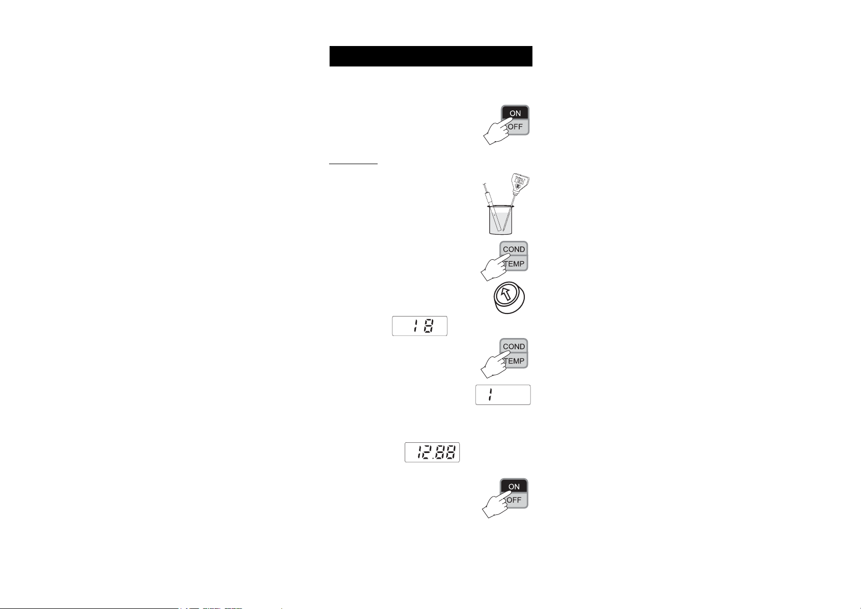
PROCEDURE FOR HI8819:
• Pour a small quantity of the conductivity so-
lution into a plastic beaker e.g. HI7030 or
HI8030 (12.88 mS/cm @ 25°C).
• Immerse the conductivity probe in the solu-
tion submerging the holes of the sleeve (0.5cm
below). Make sure that no air bubbles are
trapped inside the glass sleeve. Wait for 2 or
3 minutes for the thermal equilibrium.
• Use a CHECKTEMP or a glass thermometer
with resolution of 1° for measuring the
temperature of the solution (e.g. 18°C).
• Switch the instrument on by pressing the ON/
OFF key.
• Press COND/TEMP key to display temperature
settings.
• Adjust the TEMPERATURE knob to display
"25°C" if you are using 25°C (77°F) as reference temperature.
°C
HI 7030
TEMPERATURE
8
Page 9

• Press the COND/TEMP key to display conduc-
tivity readings and select the appropriate
conductivity range
e.g. "19.99 mS" for HI7030/HI8030,
"99.9 mS" for HI7034/HI8034,
"1999µS" for HI7031/HI8031,
"199.9 µS" for HI7033/HI8033.
• Using a small screwdriver adjust the trimmer on the rear panel
until the display shows the conductivity reading at the temperature of the solution noted earlier (see the
conductivity vs. temperature chart on page
mS
13) e.g. "11.19 mS".
CONDUCTIVITY
ELECTRODE
CAL DC POWER
12V to 20V
+
Calibration is now completed and the instrument is ready for use.
TO CHECK THE CALIBRATION
• Press the COND/TEMP key to display the tem-
perature.
• Adjust the TEMPERATURE knob to display the
temperature of the calibration solution, i.e.
the temperature noted with the CHECKTEMP
or glass thermometer.
9
TEMPERATURE
Page 10

• Press the COND/TEMP key to display conduc-
HI 7030
tivity.
• The display should read the conductivity of the
calibrating solution at the reference temperature.
E.g. using HI7030/HI8030 with a solution at 18°C, the reading will be
"12.88 mS".
PROCEDURE FOR HI8820:
• Pour a small quantity of the conductivity solu-
tion into a plastic beaker.
• Immerse the conductivity probe in the solution sub-
merging the holes of the sleeve (0.5 cm below).
Make sure that no air bubbles are trapped inside
the glass sleeve. Wait for 2 or 3 minutes for thermal
equilibrium.
• Switch the instrument on by pressing the ON/OFF
key.
• Select the appropriate conductivity range
e.g. "19.99 mS" for HI7030/HI8030,
"99.9 mS" for HI7034/HI8034,
"1999µS" for HI7031/HI8031,
"199.9 µS" for HI7033/HI8033.
• Set the temperature coefficient knob to
2%°C.
10
1.5
1
0.5
0
TEMPERATURE
COEFFICIENT
2
2.5
Page 11

• Using a small screwdriver adjust the trimmer on the rear panel
until the display shows the conductivity reading at 25°C (77°F),
e.g.: "12.88 mS" for HI7030/HI8030,
"80.00 mS" for HI7034/HI8034,
"1413 µS" for HI7031/HI8031,
"84 µS" for HI7033/HI8033.
CONDUCTIVITY
ELECTRODE
CAL DC POWER
12V to 20V
+
If you are using a different reference temperature, refer to the
conductivity vs temperature charts on page 12 for the appropriate
conductivity reading at the reference temperature.
E.g. If you prefer to standardize the temperature to 20°C (68°F)
rather than 25°C (77°F), using HI7030/HI8030, adjust the trimmer to read "11.67 mS" i.e.11670 µS (as indicated on the chart
on page 12). All subsequent measurements will be compensated
to 20° (68°F).
The calibration is now complete.
Note: The instrument should be calibrated weekly or every time the
probe has been changed.
11
Page 12
CONDUCTIVITY VERSUSCONDUCTIVITY VERSUS
CONDUCTIVITY VERSUS
CONDUCTIVITY VERSUSCONDUCTIVITY VERSUS
TEMPERATURE CHARTTEMPERATURE CHART
TEMPERATURE CHART
TEMPERATURE CHARTTEMPERATURE CHART
The conductivity of an aqueous solution is the measure of its ability to
carry an electrical current by means of ionic motion.
The conductivity invariably increases with increasing temperature.
It is affected by the type and number of ions in the solution and by
the viscosity of the solution itself. Both parameters are temperature
dependent. The dependency of conductivity on temperature is expressed as a relative change per degree Celsius at a particular
temperature, commonly as percent per °C.
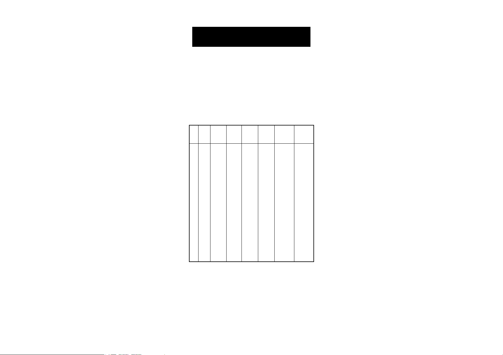
°C °F HI 7030 HI 7031 HI 7033 HI 7034 HI 7035 HI 7039
0 32 7150 776 64 48300 65400 2760
5 41 8220 896 65 53500 74100 3180
10 50 9330 1020 67 59600 83200 3615
15 59 10480 1147 68 65400 92500 4063
16 60.8 10720 1173 70 67200 94400 4155
17 62.6 10950 1199 71 68500 96300 4245
18 64.4 11190 1225 73 69800 98200 4337
19 66.2 11430 1251 74 71300 100200 4429
20 68 11670 1278 76 72400 102100 4523
21 69.8 11910 1305 78 74000 104000 4617
22 71.6 12150 1332 79 75200 105900 4711
23 73.4 12390 1359 81 76500 107900 4805
24 75.2 12640 1386 82 78300 109800 4902
25 77 12880 1413 84 80000 111800 5000
26 78.8 13130 1440 86 81300 113800 5096
27 80.6 13370 1467 87 83000 115700 5190
28 82.4 13620 1494 89 84900 117700 5286
29 84.2 13870 1521 90 86300 119700 5383
30 86 14120 1548 92 88200 121800 5479
31 87.8 14370 1575 94 90000 123900 5575
HI 8030 HI 8031 HI 8033 HI 8034 HI 8035 HI 8039
(µS/cm) (µS/cm) (µS/cm) (µS/cm) (µS/cm) (µS/cm)
E.g.: If you are calibrating HI8819 using HI7030/HI8030 (12880
mS/cm @ 25°C) as buffer solution and the solution temperature is 18°C, set the temperature reference to 25°C and turn the
trimmer to display "11.19 mS".
12
Page 13

TEMPERATURE COMPENSATIONTEMPERATURE COMPENSATION
TEMPERATURE COMPENSATION
TEMPERATURE COMPENSATIONTEMPERATURE COMPENSATION
The conductivity of an aqueous solution is the measure of its ability to
carry an electrical current by means of ionic motion. The conductivity
invariably increases with increasing temperature. It is affected by the
type and number of ions in the solution and by the viscosity of the
solution itself. Both parameters are temperature dependent. The dependency of conductivity on temperature is expressed as a relative
change per degree Celsius at a particular temperature, commonly as
percent/°C. Acids, alkalis and concentrated salt solutions have lower
values, typically 1.5%/°C. Since a small difference in temperature
causes a large change in conductivity readings particularly at high
and low temperatures, the readings are usually normalized at 25°C.
The HI8819 manually compensates for temperature differences with a
fixed ß at 2%.
The HI8820 automatically compensates for temperature differences
with a built-in NTC sensor circuitry. A knob is also provided to adjust
the temperature coefficient manually from 0% (without compensation) to 2.5% per degree Celsius.
13
Page 14

DETERMINATIONDETERMINATION
DETERMINATION
DETERMINATIONDETERMINATION
COEFFICIENT OF A SOLUTIONCOEFFICIENT OF A SOLUTION
COEFFICIENT OF A SOLUTION
COEFFICIENT OF A SOLUTIONCOEFFICIENT OF A SOLUTION
(for HI8820 only)(for HI8820 only)
(for HI8820 only)
(for HI8820 only)(for HI8820 only)
Follow the procedure described below:
1) Immerse the probe into a sample of the solution and adjust the knob to 0% (i.e. no
compensation).
2) Condition the sample and probe at 25°C
and note the conductivity reading C25.
3) Condition the sample and probe to a temperature t°C which is approximately 5°C to
10°C different from 25°C and note the conductivity reading Ct.
4) The temperature coefficient ß of the solution is calculated with
the formula:
(Ct - C25)
ß = 100 x ---------------------------
(t - 25) x C25
The above procedure is suitable for determining the temperature
coefficient in the laboratory where the temperature of the solution
can be determined and controlled. If this is not possible e.g.
during on-site measurements, the following procedure should be
used:
a) Immerse the probe into the test solution and turn the temperature
coefficient knob to 0% (no compensation).
b) Allow the conductivity reading to stabilize (the reading should not
change by more than ±0.2 mS within 1 minute) and record the
value, C.
c) Repeat the procedure with the temperature of the solution changed
by more than 10°C. Wait for the conductivity reading to stabilize.
d) Adjust the temperature coefficient knob until the display reads the
value C as recorded earlier (point b).
e) The value indicated by the knob is the temperature coefficient of
the solution.
OFOF
OF
OFOF
THETHE
TEMPERATURETEMPERATURE
THE
TEMPERATURE
THETHE
TEMPERATURETEMPERATURE
0
2
0.5
1.51
TEMPERATURE COEFFICIENT
14
Page 15

PROBE MAINTENANCEPROBE MAINTENANCE
PROBE MAINTENANCE
PROBE MAINTENANCEPROBE MAINTENANCE
Rinse the probe with tap water after
every series of measurements. If a
more thorough cleaning is required,
remove the glass sleeve and clean
the probe with a cloth or a nonabrasive detergent.
After cleaning the probe, re-calibrate
the instrument.
The four ring platinum probe body
and sleeve are in glass. For this
reason great care while handling the
probe must be taken.
15
Page 16

ACCESSORIESACCESSORIES
ACCESSORIES
ACCESSORIESACCESSORIES
CONDUCTIVITY BUFFER SOLUTIONS:
HI 7030L 12880 µS/cm (µmho/cm), 460mL
HI 7030M 12880 µS/cm (µmho/cm), 230mL
HI 7031L 1413 µS/cm (µmho/cm), 460mL
HI 7031M 1413 µS/cm (µmho/cm), 230mL
HI 7033L 84 µS/cm (µmho/cm), 460 mL
HI 7033M 84 µS/cm (µmho/cm), 230 mL
HI 7034L 80000 µS/cm (µmho/cm), 460mL
HI 7034M 80000 µS/cm (µmho/cm), 230mL
HI 7035L 111800 µS/cm (µmho/cm), 460mL
HI 7035M 111800 µS/cm (µmho/cm), 230mL
HI 7039L 5000 µS/cm (µmho/cm), 460mL
HI 7039M 5000 µS/cm (µmho/cm), 230mL
CONDUCTIVITY BUFFER SOLUTIONS IN FDA APPROVED BOTTLES:
HI 8030L 12880 µS/cm (µmho/cm), 460 mL
HI 8031L 1413 µS/cm (µmho/cm), 460 mL
HI 8033L 84 µS/cm (µmho/cm), 460 mL
HI 8034L 80000 µS/cm (µmho/cm), 460 mL
HI 8035L 111800 µS/cm (µmho/cm), 460 mL
HI 8039L 5000 µS/cm (µmho/cm), 460 mL
CONDUCTIVITY PROBES:
HI 7685 This probe for HI8819 uses the 4-ring method
measure conductivity. The probe cable is 1m
(3.3') long.
HI 7687 This probe for HI 8820 uses the 4-ring method
and has a built-in temperature sensor for ATC.
The probe screened cable is 1m (3.3') long.
16
Page 17

OTHER ACCESSORIES:
CHECKTEMPC Electronic thermometer (range: -50.0 to 150.0°C)
HI710005 Voltage adapter from 115VAC to 12VDC
HI710006 Voltage adapter from 230VAC to 12VDC
HI 731326 Small screwdrivers, length 90 mm, for calibration
purposes (20 pcs)
HI 76405 Electrode holder
MANBNCONR2 Instruction Manual
17
Page 18

WARRANTYWARRANTY
WARRANTY
WARRANTYWARRANTY
All Hanna Instruments meters are guaranteed for two years against
defects in workmanship and materials when used for their intended
purpose and maintained according to instructions. The electrodes
and the probes are guaranteed for a period of six months. This
warranty is limited to repair or replacement free of charge.
Damage due to accident, misuse, tampering or lack of prescribed
maintenance are not covered.
If service is required, contact the dealer from whom you purchased the
instrument. If under warranty, report the model number, date of
purchase, serial number and the nature of the failure. If the repair is
not covered by the warranty, you will be notified of the charges
incurred. If the instrument is to be returned to Hanna Instruments, first
obtain a Returned Goods Authorization number from the Customer
Service department and then send it with shipping costs prepaid.
When shipping any instrument, make sure it is properly packaged for
complete protection.
To validate your warranty, fill out and return the enclosed warranty
card within 14 days from the date of purchase.
All rights are reserved. Reproduction in whole or in part is prohibited
without the written consent of the copyright owner,
Hanna Instruments Inc., 584 Park East Drive, Woonsocket, Rhode
Island, 02895 , USA.
Hanna Instruments reserves the right to modify the design, construction and appearance of its products without advance notice.
18
Page 19

CE DECLARATION OF CONFORMITYCE DECLARATION OF CONFORMITY
CE DECLARATION OF CONFORMITY
CE DECLARATION OF CONFORMITYCE DECLARATION OF CONFORMITY
Recommendations for Users
Before using these products, make sure that they are entirely suitable for the environment in which they are used.
Operation of these instruments in residential area could cause unacceptable interferences to radio and TV equipments, requiring the operator to take all necessary steps to
correct interferences.
The metal band at the end of the sensor is sensitive to electrostatic discharges. Avoid
touching this metal band at all times.
During calibration of instruments, ESD wrist straps should be worn to avoid possible
damage to the sensor by electrostatic discharge.
Any variation introduced by the user to the supplied equipment may degrade the
instruments' EMC performance.
To avoid electrical shock, do not use these instruments when voltages at the measurement surface exceed 24VAC or 60VDC.
Use plastic beakers to minimize any EMC interferences.
To avoid damages or burns, do not perform any measurement in microwave ovens.
19
Page 20

http://www.hannainst.com
PRINTED IN PORTUGAL
MANBNCONR2 01/99
 Loading...