

Page 1
Instruction Manual
HI 8614 - HI 8614L
HI8615 - HI8615L
pH and ORP
Transmitters
pH
HI8614L
pH INDICATOR
& TRANSMITTER
These Instruments are in Compliance with the CE Directives
http://www.hannainst.com
1
Page 2

Dear Customer,
Thank you for choosing a Hanna Instruments
Product.
Please read this instruction manual carefully
before using the instrument.
This manual will provide you with all the neces-
sary information for the correct use of the
instrument, as well as a precise idea of its
versatility in a wide range of applications.
These instruments are in compliance with the
directives.
TABLE OF CONTENTS
Preliminary Examination............................ 3
General Description ................................... 3
Specifications of HI8614 & HI 8614L ........ 5
Specifications of HI 8615 & HI8615L ........ 6
Terminal Board Connections ..................... 7
pH Calibration with Automatic Temperature
Compensation (HI8614 & HI8614L) .......... 9
pH Calibration with Manual Temperature
Compensation (HI8614 & HI8614L)....... 13
ORP Calibration (HI8615 & HI8615L) .... 14
Electrode Conditioning and Maintenance . . 19
Temperature-Resistance Correlation for
HANNA pH Sensitive Glass .................... 23
Installation Procedure and Examples ...... 25
Accessories .............................................. 28
Warranty .................................................. 34
CE Declaration of Conformity ................. 35
2
Page 3

PRELIMINARY EXAMINATION
Remove the instrument from the packing
material and examine it carefully to make
sure that no damage has occurred during
shipping. If there is any noticeable damage,
notify your Dealer.
Note: Save all packing material until you
are sure that the instrument functions
correctly. All defective items must be
returned in the original packing material together with the supplied accessories.
GENERAL DESCRIPTION
HI 8614 - HI 8614L (pH) and HI 8615 HI 8615L (ORP) are 2-wire water-resistant
transmitters designed specially for long distance measurement of pH or ORP for use in
industrial applications.
Two versions are available: the standard
HI8614 or HI8615 and HI8614L or HI8615L
with an LCD.
The LCD versions allow easy verification
and monitoring of measured values and are
easier to calibrate and maintain.
The pH or ORP signal is transmitted in a 2wire current loop in the range of 4 to 20 mA.
HI8614 and HI8614L can be connected to
Hanna process instruments HI 8510T,
HI8710T or HI 8711T, recorders, computers
or any data monitoring device that accepts
4 to 20 mA input.
HI8615 and HI8615L can be connected to
Hanna meters HI8512T, HI8720T or any
recorders, computers or data monitor that
accepts 4 to 20 mA input.
3
Page 4

The transmitters use a universal BNC socket
for quick and secure connection to any electrode with a BNC connector.
For HI8614 - HI8614L: temperature compensation is performed by the transmitter's
ATC circuitry when measurements are taken
with the temperature probe attached
(HI76608, optional); it is also possible to
substitute the temperature probe with a fixed
resistor if ATC is not required.
The input is isolated from the current loop
to eliminate problems related to ground loop,
low insulation cables, multiple electrode connections, and a common mode voltage of
up to 100V ensures true differential readings.
A terminal board in the transmitter provides
for connection of power supply, pH or ORP
electrodes (and temperature probe for
HI8614 & HI 8614L).
The unit is enclosed in a protective casing
conforming to IP65 standards.
4
Page 5
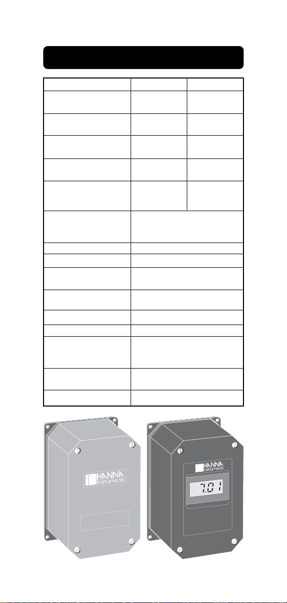
SPECIFICATIONS OF HI 8614 & HI 8614L
RANGE pH
mA
RESOLUTION pH
mA
ACCURACY pH
@20°C/68°F mA
TYPICAL EMC pH
DEVIATION mA
CALIBRATION Offset:
Slope:
TEMPERATURE
COMPENSATION
INPUT IMPEDANCE
OUTPUT
INSTALLATION
CATEGORY
POWER
LOAD
PROTECTION
ENVIRONMENT
TEMP.
RH
DIMENSIONS
WEIGHT
HI8614
----
4 to 20
----
0.01
----
±0.02
----
±0.25
±2.2 mA
±0.5 mA
HI8614L
0.00 to 14.00
4 to 20
0.01
0.01
±0.02
±0.02
±0.2
±0.25
±2.2 mA/±2 pH
±0.5 mA
86 to 116%
Fixed/automatic 0 to 100°C
(32 to 212°F) with HI76608
temp. probe (optional)
1012 ohm
4 to 20 mA isolated
II
without LCD: 18 to 30VDC
with LCD 20 to 36VDC
Max. 500 ohms
IP 65
0 to 50°C (32 to 122°F)
0-95% (non-condensing)
165 x 110 x 90 mm (L x W x H)
(6.5 x 4.3 x 3.5")
1 Kg (2.2 lb.)
HI8614
pH TRANSMITTER
pH
HI8614 L
pH INDICATOR
& TRANSMITTER
5
Page 6
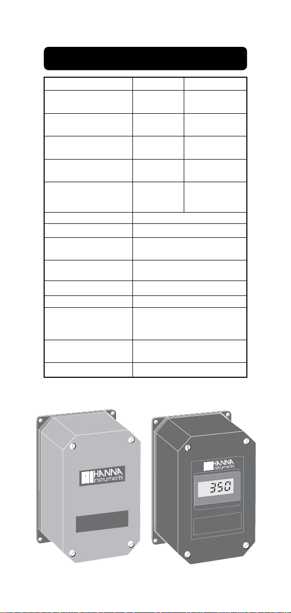
SPECIFICATIONS OF HI8615 & HI8615L
RANGE mV
mA
RESOLUTION mV
mA
ACCURACY mV
@20°C/68°F mA
TYPICAL EMC mV
DEVIATION mA
CALIBRATION Offset:
Slope:
INPUT IMPEDANCE
OUTPUT
INSTALLATION
CATEGORY
POWER
LOAD
PROTECTION
ENVIRONMENT
TEMP.
RH
DIMENSIONS
WEIGHT
HI8615
----
4 to 20
----
0.01
----
±0.02
----
±0.25
±0.8 mA
±0.8 mA
HI8615L
0 to ±1000
4 to 20
1
0.01
±5
±0.02
±15
±0.25
±0.8 mA/±100mV
±0.8 mA
90 to 110%
1012 ohm
4 to 20 mA isolated
II
without LCD: 18 to 30VDC
with LCD 20 to 36VDC
Max. 500 ohms
IP 65
0 to 50°C (32 to 122°F)
0-95% (non-condensing)
165 x 110 x 90 mm (L x W x H)
(6.5 x 4.3 x 3.5")
1 Kg (2.2 lb.)
HI 8615
ORP TRANSMITTER
mV
HI 8615
ORP TRANSMITTER
6
Page 7
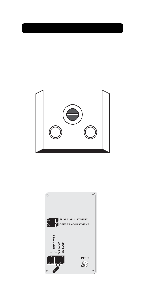
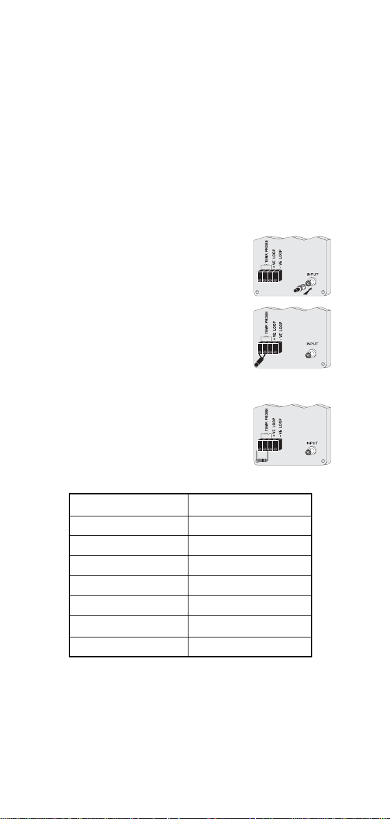
TERMINAL BOARD CONNECTIONS
Remove the 4 screws and take the top cover
off.
There are three cable glands on the cover of
the transmitter: two smaller ones and a large
one. The large cable gland with the split in the
rubber is for the electrode.
ELECTRODE
CABLE GLAND
WIRE CABLE GLANDS
Connect the positive supply to the strip terminal "+VE LOOP" and the negative supply to
the terminal "-VE LOOP" of the transmitter
terminal block.
7
Page 8
The wire between the transmitter and the
recorder/indicator/controller should be a PVC
insulated two wire with a wire diameter of at
least 0.7 mm. This wire is fed through one
of the smaller cable glands. The maximum
distance between the power supply and the
amplifier is 300 m (1000'). It is not necessary to use shielded cable. The transmitter
is protected against inversion of supply voltage.
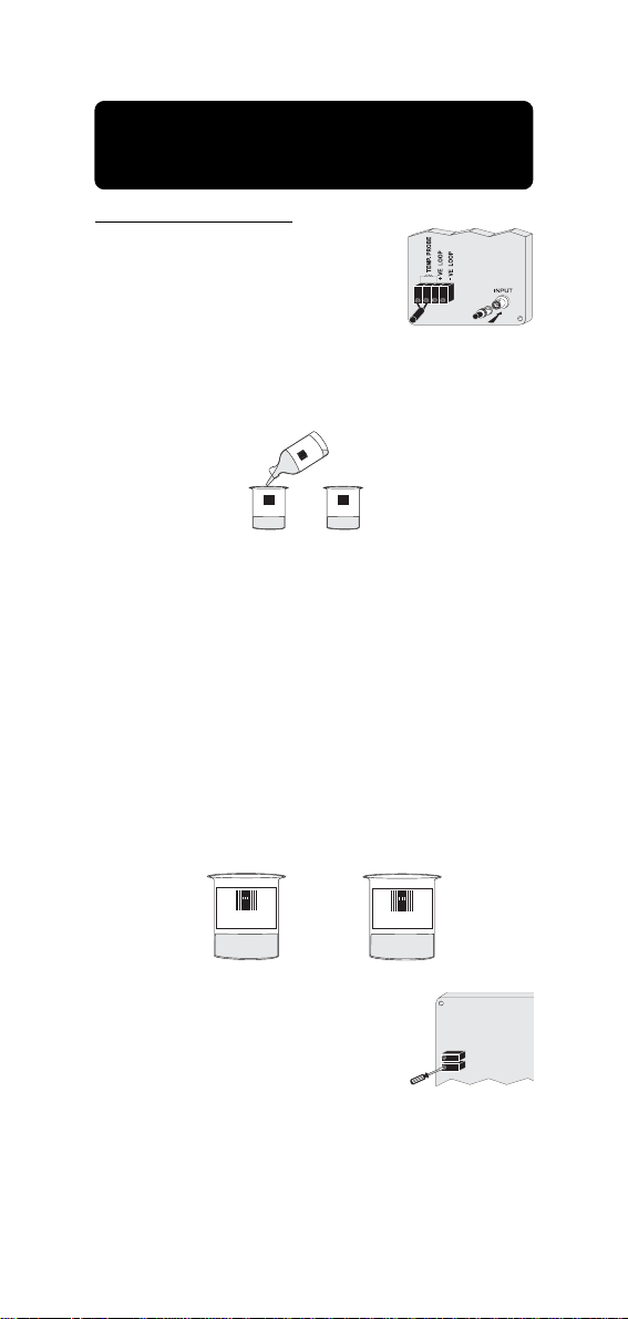
Electrode connection: connect the BNC of the cable to the
BNC socket on the transmitter.
For HI 8614 & HI 8614L only:
for automatic temperature
compensation, connect the 2
terminals of the temperature
probe (HI76608, optional) to
"TEMP. PROBE" terminals.
If automatic temperature compensation is not required, short
the "TEMP. PROBE" terminals
with a resistance according to
the external temperature:
Temperature (°C) Resistance (Ohms)
0 1634
10 1774
20 1922
30 2078
40 2242
50 2412
60 2590
A 2 kohm resistor is factory mounted for 25°C
temperature compensation.
8
Page 9
pH CALIBRATION WITH AUTOMATIC
SLOPE ADJUSTMENT
OFFSET ADJUSTMENT
TEMPERATURE COMPENSATION
(HI 8614 & HI 8614L)
Initial preparation:
• Connect the pH electrode
to the BNC socket.
• Connect the temperature
probe to the transmitter.
Pour small quantities of pH 7.01 and pH 4.01
solution into two clean beakers.
4
0
0
I 7
H
HI 7004 HI 7007
For accurate calibration use two beakers for
each buffer solution, the first one for rinsing
the electrode, the second one for calibration. In this way contamination of the buffers is minimized.
To get accurate readings, use pH7.01 and
pH 4.01 if you are going to measure acid
samples or pH 7.01 and pH 10.01 for alkaline measurements.
RINSE
HI 7007
Note: with HI8614L the instru-
ments display can be
used during calibration
without the need to connect the ammeter and the
reading is directly expressed in pH units.
9
CALIBRATION
HI 7007
Page 10
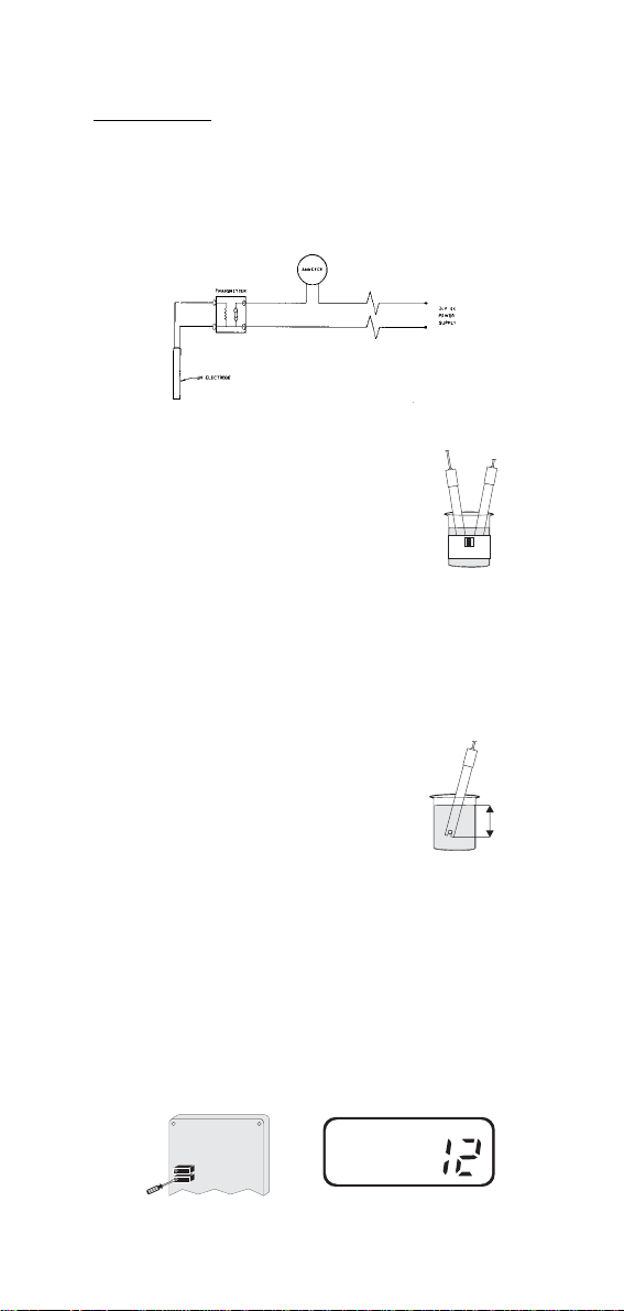
Procedure:
• Disconnect the +ve supply cable from
"+VE LOOP" terminal and connect a
20mA f.s. ammeter between the +ve
cable and "+VE LOOP" terminal.
• Remove the protective cap
from the electrode, rinse it
with some pH 7.01 solution
or immerse it in the pH 7
rinse solution, then immerse the pH electrode and
HI 7007
temperature probe into
pH 7.01 calibration buffer
solution; shake briefly and
wait for the reading to stabilize.
Note: the tip of the elec-
trode should be submerged approximately 4 cm (1½")
into the solution. The
4 cm
1½"
temperature probe
should be located as
close to the pH electrode as possible.
• Adjust the offset trimmer until the am-
meter reads 12mA or the display shows
"7.01" (HI 8614L only) if the temperature
of the buffer is at 25°C.
SLOPE ADJUSTMENT
OFFSET ADJUSTMENT
mA
10
Page 11
For other buffer temperatures, refer to
page 11 for the appropriate mA / pH
reading.
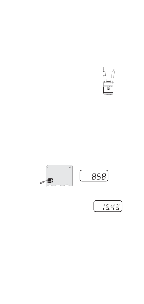
• Rinse the electrode with
tap water or distilled water
and a small amount of
pH 4.01 or 10.01 buffer solution or immerse it in the
pH4 rinse solution (2nd
calibration point). Dip the
electrode and the tempera-
HI 7004
ture probe into pH 4.01 (or
10.01) calibration buffer solution, shake briefly and
wait for a few minutes for
reading to stabilize.
• Adjust the slope trimmer until the amme-
ter reads 8.58 mA or the display shows
"4.01" at 25°C. For other buffer temperatures, refer to page 11 for the appropriate mA / pH reading (HI 8614L).
SLOPE ADJUSTMENT
OFFSET ADJUSTMENT
mA
If you are using pH 10.01
buffer solution adjust the
slope trimmer until the am-
mA
meter read 15.43mA at
25°C (77°F) or the value
indicated at page 11.
FOR HI8614L ONLY:
The Display Module is factory calibrated, so
that the LCD display results are referred to
the 4-20 mA loop current (e.g. LCD displays
0.00 pH when loop current is 4.00 mA and
displays 14.00 pH when current is 20.00mA).
11
Page 12

Under normal application, adjustment on this
module may not be necessary.
If routine check is required, the following
procedures shall be performed.
• Follow the procedure at page 7 to per-
form calibration on the transmitter module (using a ammeter).
• Simulate a 4.00 mA loop current for the
transmitter (i.e. pH 0.00 as Electrode input) and check for display reading.
• Simulate a 20.00 mA loop current for the
transmitter (i.e. pH 14.00 as Electrode
input) and check for display reading.
Note: when the instrument is used in con-
junction with the Hanna indicator
HI 8510T or controllers HI 8710T,
HI 8711T, the calibration can also be
performed on the indicator/controller.
In this case slight calibration adjustment can be made on the indicator/
controller even if the whole system
calibration is advised, always starting
from the transmitter.
12
Page 13

pH CALIBRATION WITH FIXED
TEMPERATURE COMPENSATION
(HI 8614 & HI 8614L only)
• Take the temperature of the
°C
buffer solutions using a
Checktemp or a thermometer with a resolution of at
least 1°.
• Connect the appropriate re-
sistor to the "TEMP.
PROBE" terminals (see
page6) depending on the
temperature of the calibration solution.
• Follow the procedure as outlined in the
calibration with automatic temperature
compensation and use the thermometer
reading to adjust the trimmer until the
ammeter reads the value according to
the following table.
Temperature 4.01 pH Buffer 7.01 pH Buffer 10.01 pH Buffer
°C
°F pH mA pH mA pH mA
0
32
4.01
8.576
7.13
12.137
10.32
10
15
20
25
30
35
40
45
50
55
60
5
41
4.00
8.565
7.10
50
59
68
77
86
95
104
113
122
131
140
4.00
4.00
4.00
4.01
4.02
4.03
4.04
4.05
4.06
4.07
4.09
8.565
8.565
8.565
8.576
8.587
8.599
8.610
8.622
8.633
8.645
8.667
7.07
7.04
7.03
7.01
7.00
6.99
6.98
6.98
6.98
6.98
6.98
12.103
12.069
12.034
12.023
12.000
11.989
11.977
11.966
11.966
11.966
11.966
11.966
10.24
10.18
10.12
10.06
10.01
9.96
9.92
9.88
9.85
9.82
9.79
9.77
15.789
15.697
15.629
15.560
15.491
15.434
15.377
15.331
15.285
15.251
15.217
15.182
15.159
13
Page 14

ORP CALIBRATION (HI8615 & HI8615L)
mA
Initial preparation:
Disconnect the +ve supply cable from the
"+VE LOOP" terminal and connect a 20 mA
f.s. ammeter between the +ve cable and the
"+VE LOOP" terminal. With HI 8615L the
instrument display can be used during calibration without the need to connect the ammeter. In this case the values are directly
expressed in mV units.
Pour a small quantity of
HI 7020
HI7020 ORP solution into a
beaker.
Procedure:
• Connect the shorting BNC
connector to the ORP transmitter.
• Adjust the OFFSET ADJUSTMENT trimmer on the module for a display of 12 mA
on the ammeter or 0 mV on the instrument display (HI 8615L only). This sets
the zero point for the transmitter.
SLOPE ADJUSTMENT
OFFSET ADJUSTMENT
• Connect the ORP electrode to the transmitter and immerse the tip of the electrode into a beaker of HI 7020 ORP calibration solution, and check that the ammeter reading lies between 13.6 and
14.2 mA or the instrument reading is between 200 and 275 mV at 25°C (HI8615L).
HI 7020
14
mA
Page 15

• If the reading lies outside
mA
this range, adjust the slope
adjustment trimmer on the
SLOPE ADJUSTMENT
OFFSET ADJUSTMENT
transmitter for a reading just
within this range.
The unit is now calibrated.
A complete calibration of the transmitter
module is advised periodically.
This calibration procedure requires the
HI 8427 or the HI 931001 pH and ORP simulator to simulate the ORP electrode.
HI 8427 or HI 931001 produce a known signal into the system so that the faults of the
system can be isolated.
• Connect the ORP transmitter to the simulator.
• Set the simulator to 0 mV and adjust the
offset trimmer to read 12 mA on the
ammeter or 0 mV on the HI 8615L display (HI 8615L only).
SLOPE ADJUSTMENT
OFFSET ADJUSTMENT
15
Page 16

• Set the simulator to 350 mV and adjust
the slope trimmer to read 14.8 mA on
the ammeter or 350 mV on the HI 8615L
display (HI 8615L only).
SLOPE ADJUSTMENT
OFFSET ADJUSTMENT
mA
• Connect the ORP electrode to the module and immerse the tip of the electrode
into the beaker of HI 7020 ORP solution
and check that the ammeter reading lies
between 13.6 and 14.2 mA or the instrument reading is between 200 and 275mV
at 25°C (HI 8615L only).
HI 7020
mA
• Only if the reading lies outside this range, adjust the
slope adjustment trimmer
on the transmitter to reflect
SLOPE ADJUSTMENT
OFFSET ADJUSTMENT
a reading within this range.
16
Page 17

FOR HI8615L ONLY:
The HI 8615L is factory calibrated, and the
displayed values are referenced to the 4-20
mA loop current (e.g. LCD displays -1000
mV when loop current is 4.00 mA and displays +1000 mV when current is 20.00mA).
Under normal application, adjustment on this
module may not be necessary. If routine
check is required, the following procedures
shall be performed.
• Follow the above procedure for HI 8615
(see page 12).
• Simulate a 12.00 mA loop current for the
transmitter (i.e. 0 mV at Electrode input)
and check display reading.
• Simulate a 20.00 mA loop current for the
transmitter (e.g. +1000 mV at Electrode
input) and check display reading.
17
Page 18

Please note:
-1000 mV = 4 mA
0 mV = 12 mA
1000 mV = 20 mA
350 mV = 14.8 mA
200 mV = 13.6 mA
275 mV = 14.2 mA
1 mV = 12.008 mA
Note: when the meter is used in conjunction
with the Hanna indicator HI 8512T, or
the controller HI 8720T, the calibration can also be performed on the
indicator/controller. In this case slight
adjustment can be made on the indicator/controller even if the whole system calibration is advised, always starting from the transmitter.
18
Page 19

ELECTRODE CONDITIONING
AND MAINTENANCE
Reference
Filling Hole
Reference
Filling Hole
Sensitive
Wire
Reference
Wire
Reference
Junction
Glass
Bulb
Reference
Wire
Reference
Junction
Platinum or
Gold tip
Plastic Body
pH Electrode
Reference
Plastic Body
ORP Electrode
Glass Body
pH Electrode
Wire
Glass Body
ORP Electrode
Reference
Wire
Sensitive
Wire
Reference
Junction
Glass
Bulb
Reference
Junction
Platinum or
Gold tip
PREPARATION
Remove the protective cap.
DO NOT BE ALARMED IF ANY SALT DE-
POSITS ARE PRESENT.
This is normal with electrodes and they will
disappear when rinsed with water.
During transport tiny bubbles of air may have
formed inside the glass bulb. The electrode
cannot function properly under these conditions. These bubbles can be removed by
"shaking down" the electrode as you would
19
Page 20

do with a glass thermometer.
If the bulb and/or junction are dry, soak the
electrode in HI70300 or HI80300 Storage
Solution for at least one hour.
For refillable electrodes:
If the fill solution (electrolyte) is more than
1cm (½") below the fill hole, add HI 7082 or
HI 8082 3,5M KCl Electrolyte Solution for
double junction or HI 7071 or HI 8071 3,5M
KCl+AgCl Electrolyte Solution for single
junction electrodes. For a faster response
unscrew the fill hole screw during measurements.
For AmpHel electrodes:
If the electrode does not respond to pH
changes, the battery is run down and the
electrode should be replaced.
MEASUREMENT
Rinse the electrode tip with distilled water.
Immerse the tip (4 cm / 1½") in the sample
and stir gently for approx. 30 seconds.
For a faster response and to avoid cross
contamination of the samples, rinse the electrode tip with a few drops of the solution to
be tested, before taking measurements.
STORAGE
To minimize clogging and assuring a quick
response time, the glass bulb and the junction should be kept moist and not allowed to
dry out. Replace the solution in the protective cap with a few drops of HI70300 or
HI80300 Storage Solution or, in its absence, Filling Solution (HI 7071 or HI 8071
for single junction or HI 7082 or HI 8082 for
double junction electrodes). Follow the Preparation Procedure above before taking measurements.
Note: NEVER STORE THE ELECTRODE
IN DISTILLED WATER OR DRY.
20
Page 21

PERIODIC MAINTENANCE
Inspect the electrode and the cable. The
cable used for connection to the meter must
be intact and there must be no points of
broken insulation on the cable or cracks on
the electrode stem or bulb. Connectors must
be perfectly clean and dry. If any scratches
or cracks are present on the electrode body,
replace the electrode. Rinse off any salt deposits with water.
For refillable electrodes:
Refill it with fresh electrolyte (HI7071 or
HI8071 for single junction or HI7082 or
HI8082 for double junction electrodes). Al-
low the electrode to stand upright for 1 hour.
Follow the Storage Procedure above.
CLEANING PROCEDURE
General Soak in Hanna HI7061 or
HI 8061 General Cleaning Solution for approximately 1 hour.
Removal of films, dirt or deposits on the
membrane/junction:
Protein Soak in Hanna HI7073 or
HI8073 Protein Cleaning Solution for 15 minutes.
Inorganic Soak in Hanna HI7074 or
HI8074 Inorganic Cleaning
Solution for 15 minutes.
Oil/grease Rinse with Hanna HI7077 or
HI 8077 Oil and Fat Cleaning
Solution.
IMPORTANT: After performing any of the
cleaning procedures rinse the electrode thoroughly with distilled water, drain and refill
the reference chamber with fresh electrolyte, (not necessary for GEL filled electrodes)
and soak the electrode in HI70300 or
HI80300 Storage Solution for at least 1
hour before taking measurements.
21
Page 22

TROUBLESHOOTING
Evaluate your electrode performance based
on the following.
• Noise (Readings fluctuate up and down)
could be due to:
- Clogged/Dirty Junction: Refer to the
Cleaning Procedure above.
- Loss of shielding due to low electro-
lyte level (in refillable electrodes only):
HI7071 or HI8071 for single junction or
HI7082 or HI8082 for double junction
electrodes.
• Dry Membrane/Junction: Soak in Storage Solution HI70300 or HI80300 for at
least 1 hour.
• Drifting: Soak the electrode tip in warm
Hanna Solution HI7082 or HI8082 for
one hour and rinse the tip with distilled
water. Refill with fresh HI7071 or HI8071
for single junction electrodes and HI7082
or HI8082 for double junction electrodes.
• Low Slope: Refer to the cleaning proce-
dure above.
• No Slope: Check the electrode for cracks
in glass stem or bulb and replace the
electrode.
• Slow Response/Excessive Drift: Soak
the tip in Hanna Solution HI7061 or
HI8061 for 30 minutes, rinse thoroughly
in distilled water and then follow the
Cleaning Procedure above.
22
Page 23

TEMPERATURE-RESISTANCE
0
0+10+20+30+40+50+60+70+80+90
C
CORRELATION FOR HANNA
pH SENSITIVE GLASS
The resistance of glass electrodes partially
depends on the temperature. The lower the
temperature, the higher the resistance. It
takes longer time for the reading to stabilize
if the resistance is higher. In addition, the
response time will suffer to a greater degree
at temperatures below 10°C.
Ω
9
2x10
-10
9
1x10
-10
8
-10
2x10
8
1x10
-10
7
2x10
-10
-10
7
1x10
-10
-20-2
°
Since the resistance of the pH electrode is
in the range of 200 Mohm, the current across
the membrane is in the pico Ampere range.
Large currents can disturb the calibration of
the electrode for many hours.
For these reasons high humidity environ-
ments, short circuits and static discharges are detrimental for a stable pH
reading.
The pH electrode's life also depends on the
temperature. If constantly used at high temperatures, the electrode life is drastically
reduced.
23
Page 24

Typical Electrode Life
Ambient Temperature 1- 3 years
90 °C Less than 4 months
120°C Less than 1 month
High concentrations of sodium ions interfere
with readings in alkaline solutions; the pH at
which the interference starts to be significant depends upon the composition of the
glass. This interference is the alkaline error
and causes the pH to be underestimated.
Hanna's glass formulations have the indicated characteristics.
Alkaline Error
Sodium Ion Correction for the Glass
at 20-25°C
Concentration pH Error
0.1 Mol L-1 Na
1.0 Mol L-1 Na
+
13.00
13.50
14.00
+
12.50
13.00
13.50
14.00
0.10
0.14
0.20
0.10
0.18
0.29
0.40
24
Page 25

INSTALLATION PROCEDURE
AND EXAMPLES
The HI8614, HI8614L, HI8615 and HI 8615L
transmitters may be wall mounted in any convenient location near the measurement point.
To minimize thermal drift due to extreme
temperature fluctuations during the measurement process, particularly if the measurement
is conducted outdoors, it is best to protect the
transmitter in an enclosed casing.
General Installation Procedure
For most industrial application involving long
term monitoring and control, it is also recommended to use tank electrode holders (HI6050
or HI6051) to protect the pH electrode and the
temperature probe from contamination by the
test solution.
Controlling the pH / ORP with a recorder
25
Page 26

Monitoring the pH/ORP with Panel Mounting
pH (HI8510)/ORP (HI8512) Indicator
Controlling the pH/ORP with
an Industrial Regulator
Monitoring and Controlling the pH/ORP
with Panel Mounting Indicator/Regulator
and Dosage Control of either Acid or Base
26
Page 27

Monitoring and Controlling the pH with
(HI 8711) Panel Mounting Indicator/
Regulator with Independent Dosage
Control for Acid and Base
27
Page 28

ACCESSORIES
pH CALIBRATION SOLUTIONS
HI7004M pH 4.01 Buffer Solution, 230 mL
HI7004L pH 4.01 Buffer Solution, 460 mL
HI7006M pH 6.86 Buffer Solution, 230 mL
HI7006L pH 6.86 Buffer Solution, 460 mL
HI7007M pH 7.01 Buffer Solution, 230 mL
HI7007L pH 7.01 Buffer Solution, 460 mL
HI7009M pH 9.18 Buffer Solution, 230 mL
HI7009L pH 9.18 Buffer Solution, 460 mL
HI7010M pH 10.01 Buffer Solution, 230mL
HI7010L pH 10.01 Buffer Solution, 460 mL
ORP SOLUTIONS
HI 7020M 200-275mV Buffer Solution, 230 mL
HI 7020L 200-275mV Buffer Solution, 460 mL
HI 7091M Pre-Treatment Reducing Solution,
230 mL
HI 7091L Pre-Treatment Reducing Solution,
460 mL
HI 7092M Pre-treatment Oxidizing Solution,
230 mL
HI 7092L Pre-Treatment Oxidizing Solution,
460 mL
ELECTRODE STORAGE SOLUTIONS
HI70300MStorage Solution, 230 mL
HI70300L Storage Solution, 460 mL
ELECTRODE CLEANING SOLUTIONS
HI7061M General Cleaning Sol., 230 mL
HI7061L General Cleaning Sol., 460 mL
HI7073M Protein Cleaning Sol., 230 mL
HI7073L Protein Cleaning Sol., 460 mL
HI7074M Inorganic Cleaning Sol., 230 mL
HI7074L Inorganic Cleaning Sol., 460 mL
HI7077M Oil & Fat Cleaning Sol., 230 mL
HI7077L Oil & Fat Cleaning Sol., 460 mL
REFILLING ELECTROLYTE SOLUTIONS
HI7071 3.5M KCl + AgCl Electrolyte,
4x50 mL, for single junction electrodes
HI7072 1M KNO3 Electrolyte, 4x50 mL
HI7082 3.5M KCl Electrolyte, 4x50 mL,
for double junction electrodes
28
Page 29

pH ELECTRODES
DIA 9.5mm
3/4 x 16 UNF
DIA 12mm
110mm
38.5mm
DIA 20.5mm
HI 1090T Screwcap PG13.5 connector,
double junction, glass-body
PG13.5 THREAD
φ 12mm φ 9.5mm
110mm30mm
HI 1110S Screw connector, single junction,
glass-body
HI 1130B/3 BNC connector, 3 m (9.9') cable,
single junction, glass-body
M13 x 1.5
DIA
16
mm
25
7
mm
mm
HI 1110S HI 1130B/3
HI 1110T Screwcap PG13.5 connector,
double junction, glass-body
PG13.5 THREAD
φ 12mm φ 9.5mm
HI 1114S Screw connector, double junc-
110mm30mm
tion plastic-body
HI 1134B/3 BNC connector, 3 m (9.9') cable,
double junction plastic-body
DIA
16
mm
3/4 x 16 UNF
DIA 20.5mm
38.5mm
M13 x 1.5
25
7
mm
mm
HI 1114S HI 1134B/3
DIA 12mm
110mm
HI 1115S Screw connector, single junction,
glass-body
HI 1135B/3 BNC connector, 3 m (9.9') cable,
single junction, glass-body
DIA 16.5mm
5mm
M13 x 1.5
DIA
16
mm
25
7
mm
mm
HI 1115S HI 1135B/3
DIA 7.6mm
25mm
29
DIA 12mm
150mm
Page 30

HI 1210T Screwcap PG13.5 connector,
DIA 20.5mm
DIA 9.5mm
3/4 x 16 UNF
DIA 12mm
110mm
38.5mm
double junction, plastic-body
PG13.5 THREAD
φ 12mm
110mm30mm
HI 1910B BNC connector, 1 m (3.3') cable,
double junction, plastic-body,
built-in amplifier
3/4 x 16 UNF
DIA 20.5mm
DIA 12mm
38.5mm
110mm
HI 1911B BNC connector, 1 m (3.3') cable,
double junction, plastic-body,
built-in amplifier
3/4 x 16 UNF
DIA 20.5mm
38.5mm
DIA 12mm
110mm
HI 1912B BNC connector, 1 m (3.3') cable,
double junction, plastic-body,
built-in amplifier
HI 1912B/5 BNC connector, 5 m (16.5') cable,
double junction, plastic-body,
built-in amplifier
HI 2114B/5 BNC connector, 5 m (16.5') cable,
double junction, plastic-body
3/4 x 16 UNF
DIA 20.5mm
DIA 12mm
38.5mm
110mm
30
Page 31

HI 2910B/5 BNC connector, 5 m (16.5') cable,
double junction, plastic-body,
built-in amplifier
3/4 x 16 UNF
DIA 20.5mm
DIA 12mm
38.5mm
110mm
ORP ELECTRODES
HI 2930B/5 BNC connector, 5 m (16.5') cable,
Pt, Ultem®-body, built-in amplifier
3/4 x 16 UNF
DIA 20.5mm
38.5mm
DIA 12mm
110mm
HI 3110S Screw-type connector, Pt, glass-
body
HI 3130B/3 BNC connector, 3 m (9.9') cable,
Pt, glass-body
DIA
mm
16
3/4 x 16 UNF
DIA 20.5mm
38.5mm
DIA 12mm
110mm
M13 x 1.5
25
7
mm
mm
HI 3110S HI 3130B/3
HI 3110T Screwcap PG13.5 connector, Pt,
glass-body
PG13.5 THREAD
φ 12mm φ 1mm
110mm30mm
HI 3115S Screw-type connector, side-arm,
Pt, glass-body
HI 3135B/3 BNC connector, 3 m (9.9') cable,
side-arm, Pt, glass-body
DIA 16.5mm
5mm
M13 x 1.5
DIA
16
mm
25
7
mm
mm
HI 3115S HI 3135B/3
Ultem® is a registered Trademark of "General Electrics Company"
DIA 7.6mm
25mm
31
DIA 12mm
150mm
Page 32

HI 3210T Screwcap PG13.5 connector, Pt,
plastic-body
PG13.5 THREAD
φ 12mm
110mm30mm
HI 3410S Screw connector, Pt, plastic-body
HI 3430B/3 BNC connector, 3 m (9.9') cable,
Pt, plastic-body
DIA
16
mm
3/4 x 16 UNF
DIA 20.5mm
38.5mm
M13 x 1.5
25
7
mm
mm
HI 3410S HI 3430B/3
DIA 12mm
110mm
HI 3932B/5 BNC connector, 5 m (16.5') cable,
Pt, Ultem®-body, built-in amplifier
3/4 x 16 UNF
DIA 20.5mm
DIA 12mm
38.5mm
110mm
HI 4110S Screw-type connector, Au, glass-
body
HI 4130B/3 BNC connector, 3 m (9.9') cable,
Au, glass-body
DIA
16
mm
3/4 x 16 UNF
DIA 20.5mm
M13 x 1.5
25
7
mm
mm
HI 4110S HI 4130B/3
38.5mm
DIA 12mm
110mm
HI 4932B/5 BNC connector, 5 m (16.5') cable,
Au, Ultem®-body, built-in amplifier
3/4 x 16 UNF
DIA 20.5mm
38.5mm
Ultem® is a registered Trademark of "General Electrics Company"
32
DIA 12mm
110mm
Page 33

EXTENSION CABLES FOR SCREW-TYPE
ELECTRODES ONLY (SCREW TO BNC
CONNECTOR)
HI 7855 SERIES CABLE CONNECTORS
CONNECTOR AND 3.0 mm (0.12") CABLE WITH BNC
CONNECT TO
SCREW TYPE
ELECTRODES
CONNECT TO THE
BNC SOCKET
OF THE METER
HI7855/1 Extension cable 1m (3.3') long
HI7855/3 Extension cable 3m (9.9') long
HI7855/5 Extension cable 5m (16.5') long
HI7855/10 Extension cable 10m (33') long
HI7855/15 Extension cable 15m (49.5') long
OTHER ACCESSORIES
BL PUMPS Dosing Pumps with Flow Rate
from 1.5 to 20 LPH
ChecktempC Pocket-size thermometer with
penetration probe and 0.1°C
resolution (range -50.0 to
150.0°C)
HI6050 Submersible Electrode Holders
& HI 6051
HI 6054 Electrode Holders for In-Line
& HI 6057 Applications
HI76501/P Calibration Screwdriver (20 pcs)
HI 7871 Level Controllers
& HI 7873
HI8427 pH and ORP Electrode
Simulator with 1 m (3.3') Coaxial
Cable ending in Female BNC
Connectors (HI 7858/1)
HI931001 pH and ORP Electrode
Simulator with LCD Display and
1 m (3.3') Coaxial Cable ending
in Female BNC Connectors
(HI 7858/1)
MANPHTRR2 Instruction Manual
33
Page 34

WARRANTY
All Hanna Instruments meters are warranted
for two years against defects in workman-
ship and materials when used for their intended purpose and maintained according
to instructions.
The probes and the electrodes are warranted for a period of six months.
Damages due to accident, misuse, tampering or lack of prescribed maintenance are
not covered. This warranty is limited to repair or replacement free of charge.
If service is required, contact the dealer
from whom you purchased the instrument. If
under warranty, report the model number,
date of purchase, serial number and the
nature of the failure. Obtain a Returned
Goods Authorization from the Customer Service department first and then return the
instrument with the Authorization # included
along with shipment costs prepaid. If the
repair is not covered by the warranty, you
will be notified of the charge for repair or
replacement. When shipping any instrument,
make sure it is properly packaged for complete protection.
To validate your warranty, fill out and return
the enclosed warranty card within 14 days
from the date of purchase.
All rights are reserved. Reproduction in whole
or in part is prohibited without the written
consent of the copyright owner.
Hanna Instruments reserves the right to
modify the design, construction and appearance of its products without advance
notice.
34
Page 35

CE DECLARATION OF CONFORMITY
Recommendations for Users
Before using these products, make sure that they are entirely suitable for the environment
in which they are used.
Operation of these instruments in residential area could cause unacceptable interferences to radio and TV equipments, requiring the operator to take all necessary steps to
correct interferences.
Any variation introduced by the user to the supplied equipment may degrade the
instruments' EMC performance.
To avoid damages or burns, do not perform any measurement in microwave ovens.
35
Page 36

06/01
http://www.hannainst.com
36
MANPHTRR2
 Loading...