

Page 1

IMAGETEAM™ 4410/4710
2D Series Hand Held Imager
™
User’s Guide
Page 2

Statement of Agency Compliance
This device complies with part 15 of the FCC Rules. Operation is subject to the
following two conditions: (1) this device may not cause harmful interference, and
(2) this device must accept any interference received, including interference that
may cause undesired operation.
FCC Class B Compliance Statement
This equipment has been tested and found to comply with the limits for a Class
B digital device pursuant to part 15 of the FCC Rules. These limits are designed
to provide reasonable protection against harmful interference in a residential
installation. This equipment generates, uses, and can radiate radio frequency
energy and, if not installed and used in accordance with the instructions, may
cause harmful interference to radio communications. However, there is no
guarantee that interference will not occur in a particular installation. If this
equipment does cause harmful interference to radio or television reception,
which can be determined by turning the equipment off and on, the user is
encouraged to try to correct the interference by one or more of the following
measures:
• Reorient or relocate the receiving antenna.
• Increase the separation between the equipment and receiver.
• Connect the equipment into an outlet on a circuit different from that to which
the receiver is connected.
• Consult the dealer or an experienced radio or television technician for help.
Caution: Any changes or modifications made to this device that are not
expressly approved by Hand Held Products, Inc. may void the user’s authority to
operate the equipment.
Note: To maintain compliance with FCC Rules and Regulations, cables
connected to this device must be shielded cables, in which the cable shield
wire(s) have been grounded (tied) to the connector shell.
Canadian Notice
This equipment does not exceed the Class B limits for radio noise emissions as
described in the Radio Interference Regulations of the Canadian Department of
Communications.
Le present appareil numerique n’emet pas de bruits radioelectriques depassant
les limites applicables aux appareils numeriques de la classe B prescrites dans
le Reglement sur le brouillage radioelectrique edicte par le ministere des
Communications du Canada.
Page 3

LED Safety Statement
This device has been tested in accordance with EN60825-1 LED safety, and has
been certified to be under the limits of a Class 1 LED device.
The CE mark on the product indicates that the system has been tested
to and conforms with the provisions noted within the 89/336/EEC
Electromagnetic Compatibility Directive and the 73/23/EEC Low
Voltage Directive.
For further information please contact:
Hand Held Products, Inc.
Nijverheidsweg 9
5627 BT Eindhoven
The Netherlands
Hand Held Products shall not be liable for use of our product with equipment (i.e.,
power supplies, personal computers, etc.) that is not CE marked and does not
comply with the Low Voltage Directive.
Patents
Please refer to the product packaging for patent information.
Disclaimer
Hand Held Products, Inc. (“Hand Held Products”) reserves the right to make
changes in specifications and other information contained in this document
without prior notice, and the reader should in all cases consult Hand Held
Products to determine whether any such changes have been made. The
information in this publication does not represent a commitment on the part of
Hand Held Products.
Hand Held Products shall not be liable for technical or editorial errors or
omissions contained herein; nor for incidental or consequential damages
resulting from the furnishing, performance, or use of this material.
This document contains proprietary information that is protected by copyright. All
rights are reserved. No part of this document may be photocopied, reproduced,
or translated into another language without the prior written consent of Hand
Held Products.
© 2005 Hand Held Products, Inc. All rights reserved.
Web Address: www.handheld.com
Page 4

Page 5

Table of Contents
Chapter 1 - Introduction and Installation
About the Hand-Held and Fixed Mount 2D Imager............. 1-1
Unpacking the Imager........................................................... 1-2
IT4410 Imager Identification................................................ 1-4
IT4710 Imager Identification................................................ 1-5
Connecting the Scanner in Keyboard Wedge Mode............. 1-6
Connecting the Scanner to a Serial Port...............................1-7
Reading Techniques.............................................................. 1-8
Chapter 2 - Programming
Introduction........................................................................... 2-1
Reset Factory Settings .......................................................... 2-2
Status Check ......................................................................... 2-2
All Symbologies ................................................................... 2-2
Revision Selections............................................................... 2-3
Terminal Interface ................................................................ 2-4
Supported Terminals Chart................................................... 2-5
Keyboard Country ................................................................ 2-6
Keyboard Style ..................................................................... 2-7
Keyboard Modifiers.............................................................. 2-8
Keyboard Function Relationships......................................... 2-9
Communication Settings..................................................... 2-10
Parity............................................................................ 2-10
Baud Rate..................................................................... 2-11
Word Length Data Bits ................................................ 2-12
Word Length Stop Bits................................................. 2-12
Hardware Flow Control................................................ 2-13
Software Flow Control................................................. 2-13
Serial Triggering .......................................................... 2-14
Trigger Timeout.................................................................. 2-15
Power Saving Mode............................................................ 2-16
Power Hold Mode............................................................... 2-17
LED Power Level............................................................... 2-17
LED Flashing...................................................................... 2-18
i
Page 6

Aimer Delay........................................................................ 2-18
Aimer Interval..................................................................... 2-19
Centering............................................................................. 2-20
AutoTrigger ........................................................................ 2-23
Scan Stand .......................................................................... 2-23
Scan Stand Symbol ...................................................... 2-24
Presentation Mode.............................................................. 2-24
Presentation Re-trigger Delay...................................... 2-24
Presentation Lights....................................................... 2-25
Presentation Default..................................................... 2-25
Fast Omni Mode................................................................. 2-26
Beeper Volume................................................................... 2-26
Power Up Beeper................................................................ 2-27
Output Sequence Beeper..................................................... 2-27
Beep On Decode................................................................. 2-27
Beeper Default ............................................................. 2-27
Intercharacter, Interfunction,
and Intermessage Delays.................................................. 2-28
Intercharacter Delay .................................................... 2-28
User Specified Intercharacter Delay ........................... 2-28
Interfunction Delay ..................................................... 2-29
Intermessage Delay ..................................................... 2-30
Prefix/Suffix Overview....................................................... 2-31
Adding a Prefix or Suffix............................................. 2-32
Add a Carriage Return Suffix to All Symbologies ..... 2-33
Add a Code I.D. Prefix to All Symbologies ................ 2-33
Add an AIM I.D. Prefix to All Symbologies .............. 2-33
Prefix Entries................................................................ 2-34
Suffix Entries ............................................................... 2-34
Symbology Chart................................................................ 2-35
Decimal to Hex to ASCII Conversion Chart...................... 2-36
ii
Page 7

Data Format Editor Overview............................................. 2-37
Format Editor Commands............................................2-38
Data Format Editor.......................................................2-40
Data Formatter.............................................................. 2-41
Require Data Format ....................................................2-41
Show Data Formats......................................................2-41
Alternate Data Formats ................................................2-42
Output Sequence Overview ................................................ 2-43
Require Output Sequence.............................................2-44
Output Sequence Editor................................................2-46
Multiple Symbols................................................................2-47
No Read ..............................................................................2-47
Print Weight........................................................................ 2-48
Function Code Transmit .....................................................2-48
Video Reverse.....................................................................2-49
Chapter 3 - Symbologies
Introduction...........................................................................3-1
Codabar................................................................................. 3-2
Start/Stop Characters......................................................3-2
Message Length.............................................................. 3-2
Check Character .............................................................3-3
Code 39.................................................................................3-4
Start/Stop Characters......................................................3-4
Message Length.............................................................. 3-5
Full ASCII......................................................................3-5
Check Character .............................................................3-6
Code 11.................................................................................3-7
Message Length.............................................................. 3-7
Check Digits Required ................................................... 3-8
Interleaved 2 of 5..................................................................3-9
Message Length.............................................................. 3-9
Check Digit...................................................................3-10
IATA 2 of 5......................................................................... 3-11
Message Length............................................................ 3-11
iii
Page 8

MSI..................................................................................... 3-12
Message Length ........................................................... 3-12
Check Digit .................................................................. 3-13
Code 93............................................................................... 3-14
Message Length ........................................................... 3-14
Code 128............................................................................. 3-15
Message Length ........................................................... 3-15
ISBT.................................................................................... 3-16
EAN/JAN 8......................................................................... 3-17
Check Digit .................................................................. 3-17
EAN/JAN 8 Addenda................................................... 3-18
EAN/JAN 8 Addenda Required................................... 3-18
EAN/JAN 8 Addenda Separator .................................. 3-18
EAN/JAN 13....................................................................... 3-19
Check Digit .................................................................. 3-19
EAN/JAN 13 Addenda................................................. 3-20
EAN/JAN 13 Addenda Required................................. 3-20
EAN/JAN 13 Addenda Separator ................................ 3-20
UPC A................................................................................. 3-21
Check Digit .................................................................. 3-21
Number System............................................................ 3-21
UPC A Addenda........................................................... 3-22
UPC A Addenda Required........................................... 3-22
UPC A Addenda Separator .......................................... 3-22
UPC E0............................................................................... 3-23
Check Digit .................................................................. 3-23
Number System............................................................ 3-23
Version E Expand ........................................................ 3-24
UPC E1............................................................................... 3-24
UPC E0/E1 Addenda.................................................... 3-24
UPC E0/E1 Addenda Required.................................... 3-25
UPC E0/E1 Addenda Separator................................... 3-25
RSS-14................................................................................ 3-26
RSS-14 Limited.................................................................. 3-26
RSS-14 Expanded............................................................... 3-27
Message Length ........................................................... 3-27
iv
Page 9

Codablock...........................................................................3-28
Message Length............................................................ 3-28
PDF417...............................................................................3-29
Message Length............................................................ 3-29
MicroPDF417 .....................................................................3-30
Message Length............................................................ 3-30
Code 49...............................................................................3-31
Message Length............................................................ 3-31
EAN•UCC Composite Codes ............................................. 3-32
Message Length............................................................ 3-32
TLC39................................................................................. 3-33
U.S. Postal Service POSTNET Code.................................. 3-34
Check Digit...................................................................3-34
Planet Code.........................................................................3-34
Check Digit...................................................................3-34
British Post Office 4 State Code ........................................3-35
Canadian 4 State Code........................................................ 3-35
Dutch Postal Code...............................................................3-35
Australian 4 State Code ......................................................3-35
Japanese Postal Service.......................................................3-35
QR Code..............................................................................3-36
Message Length............................................................ 3-36
Data Matrix.........................................................................3-37
Message Length............................................................ 3-37
MaxiCode............................................................................ 3-38
Message Length............................................................ 3-38
Structured Carrier Message Only................................. 3-39
Aztec Code..........................................................................3-40
Message Length............................................................ 3-40
Test Menu .......................................................................... 3-41
2D PQA (Print Quality Assessment) .................................. 3-41
Chapter 4 - OCR Programming
Introduction...........................................................................4-1
OCR ...................................................................................... 4-2
OCR Direction................................................................ 4-3
v
Page 10

Creating OCR Templates...................................................... 4-4
Creating an OCR Template............................................ 4-4
Stringing Together Multiple Formats
(Creating “Or” Statements)............................................ 4-6
Creating a User-Defined Variable.................................. 4-6
Adding an OCR Check Character.................................. 4-7
OCR Template Codes .................................................... 4-9
Chapter 5 - Default Charts
Communication (RS-232) Selections............................. 5-1
Imager Selections........................................................... 5-1
Prefix/Suffix Selections................................................. 5-2
Data Formatter Selections.............................................. 5-2
Output Sequence Selections........................................... 5-2
Linear Symbologies ....................................................... 5-2
Postal Symbology Selections......................................... 5-4
2D Matrix Selections...................................................... 5-4
OCR Selections.............................................................. 5-5
Chapter 6 - Software Development Kit
Software Development Kit (SDK)........................................ 6-1
Features of the SDK.............................................................. 6-1
Chapter 7 - Quick*View
Quick*View Demonstration Software Instructions.............. 7-1
Setting Up the Imager and the Quick*View Software... 7-1
Installing Quick*View from the Web................................... 7-1
Using the Quick*View Software.......................................... 7-3
Load New Imager Software........................................... 7-8
Serial Programming Commands.................................... 7-9
Query Commands .............................................................. 7-11
Trigger Commands............................................................. 7-12
Serial Programming Commands ........................................ 7-14
vi
Page 11

Imaging Commands ........................................................... 7-27
Image Commands Help File.........................................7-27
Image Ship.................................................................... 7-27
Image Capture/Ship and Image Get Commands..........7-28
Image Cropping/Shipping Example.............................7-29
Intelligent Signature Capture Commands .................... 7-29
Chapter 8 - Visual Menu
Visual Menu Introduction..................................................... 8-1
Installing Visual Menu from the Web............................8-2
Chapter 9 - Interface Keys
Chapter 10 - Product Specifications & Pinouts
Product Specifications - IT4410 ......................................... 10-1
Product Specifications - IT4710 ......................................... 10-2
Depth of Field Charts..........................................................10-4
Cable Pinouts......................................................................10-6
Connector Part Numbers..............................................10-7
IT4410 Dimensions............................................................. 10-8
IT4710 Dimensions............................................................. 10-9
Chapter 11 - Maintenance & Troubleshooting
Repairs ................................................................................ 11-1
Maintenance........................................................................11-1
Replacing the Interface Cable ...................................... 11-2
Troubleshooting..................................................................11-3
Chapter 12 - Customer Support
Product Service and Repair................................................. 12-1
Online Product Service and Repair Assistance............12-2
Technical Assistance........................................................... 12-2
Online Technical Assistance ........................................12-2
Limited Warranty................................................................12-2
vii
Page 12

viii
Page 13

1
Introduction and Installation
About the Hand-Held and Fixed Mount 2D Imager
The hand-held and fixed mount 2D Imager is an economical, durable solution for
a wide variety of data collection applications. The Imager features the following:
• A tough, ergonomic thermoplastic housing for comfort and durability.
• Omni-directional reading of a variety of printed symbols, including the most
popular linear and 2D matrix symbologies.
• RS-232, keyboard wedge, and laser emulation communication outputs.
• The ability to capture and download images to a PC for signature capture
software applications, and PC-based decoding.
• The ability to read OCR fonts.
About this Manual
This user’s guide provides installation instructions for the hand-held Imager. The
chapters contain the following information:
Chapter 1 Unpacking and installing the Imager
Chapter 2 Programming selections
Chapter 3 Symbology programming selections
Chapter 4 OCR programming
Chapter 5 Default settings
Chapter 6 Software Developers Kit
Chapter 7 Quick*View software information and serial programming
Chapter 8 Visual Menu software
Chapter 9 Interface Keys
Chapter 10 Product Specifications & Pinouts
Chapter 11 Maintenance and troubleshooting
Chapter 12 Customer support, service information, and warranty
commands
IMAGETEAM™ 4410/4710 User’s Guide 1 - 1
Page 14
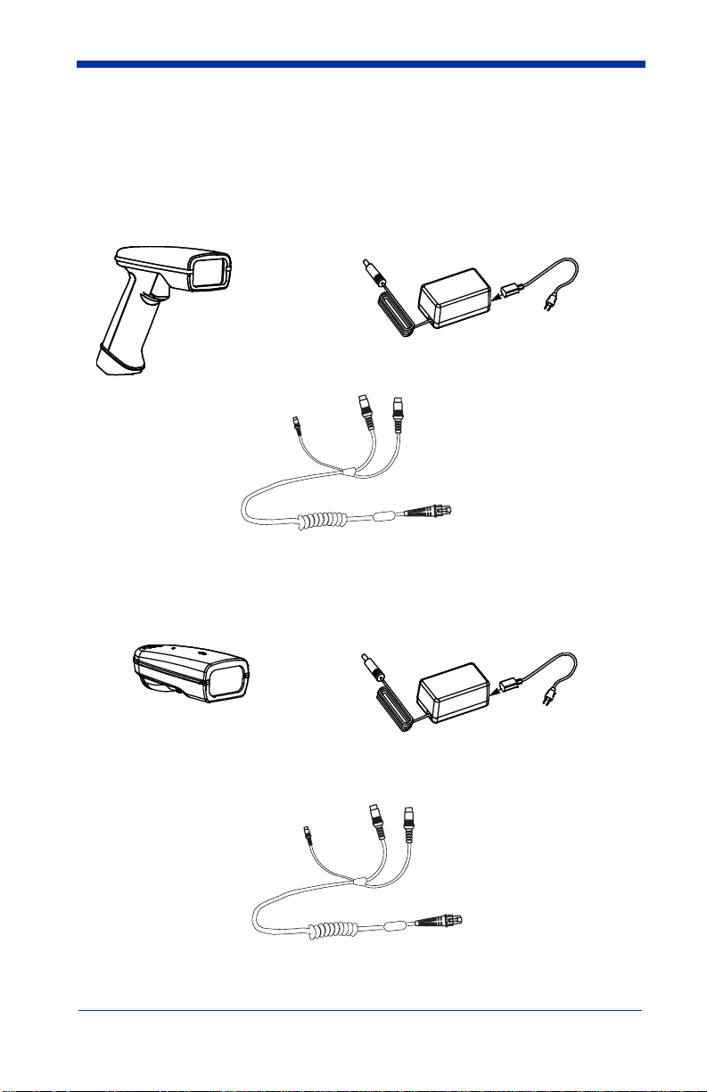
Unpacking the Imager
Open the carton. The shipping carton or container should contain:
IMAGETEAM 4410 Convenience Kit:
IMAGETEAM 4410 Hand
Held Imager
Cable
IMAGETEAM 4710 Convenience Kit:
IMAGETEAM 4710 Hand
Held/Fixed Mount Imager
Universal Power Supply
and Power Cable
Universal Power Supply
and Power Cable
Cable
1 - 2 IMAGETEAM™ 4410/4710 User’s Guide
Page 15

• Check to make sure everything you ordered is present.
• Save the shipping container for later storage or shipping.
• Check for damage during shipment. Report damage immediately to the
carrier who delivered the carton.
IMAGETEAM™ 4410/4710 User’s Guide 1 - 3
Page 16
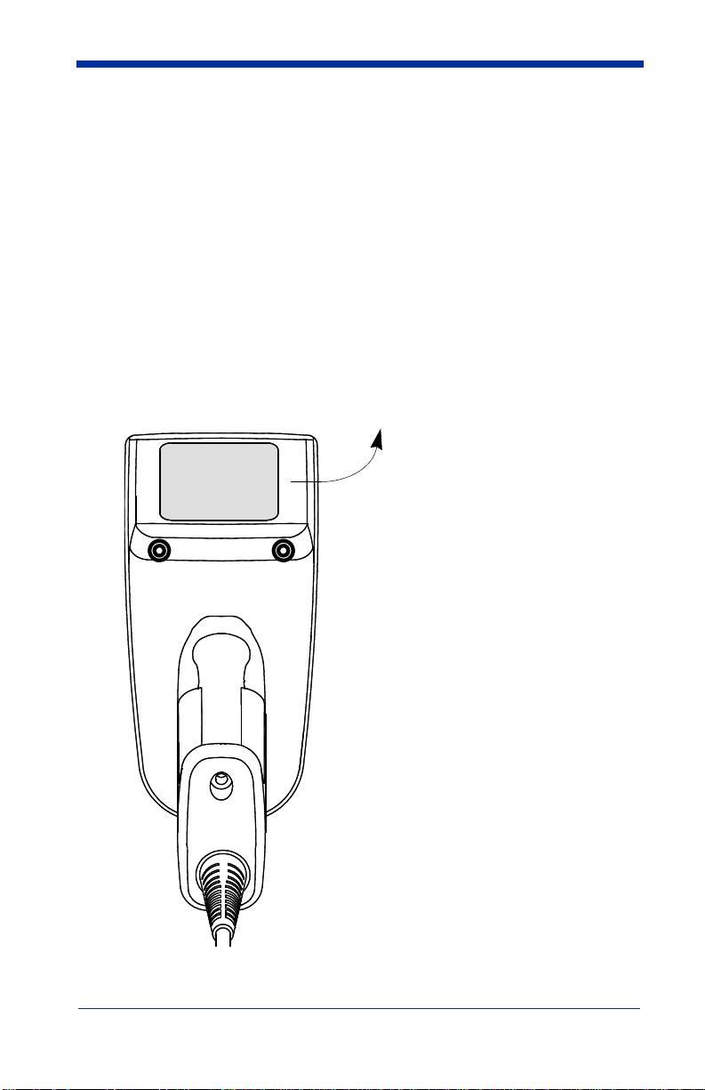
IT4410 Imager Identification
Model # - 4410XX-XX
Manufactured - August 2002
Serial # = P-12-34567
S/W = 34567001/4410
Enlarged View of Label
Hand Held IT4410 Imager
Bottom View
1 - 4 IMAGETEAM™ 4410/4710 User’s Guide
Page 17
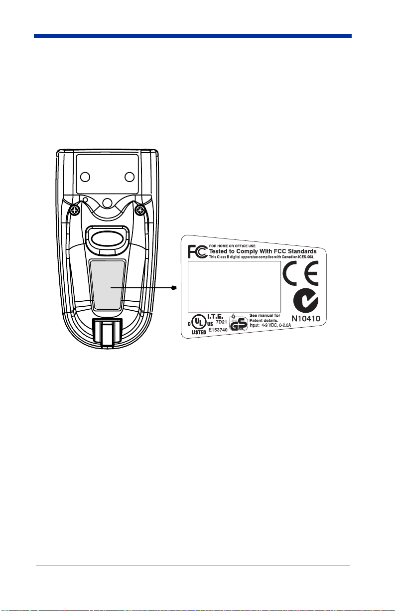
IT4710 Imager Identification
Hand Held IT4710 Imager
Bottom View
ITEM # IT4710
DATE / SN:
S / W Rev:
Hand Held Products
Skaneateles Falls, NEW YORK
13153
IMAGETEAM™ 4410/4710 User’s Guide 1 - 5
Page 18
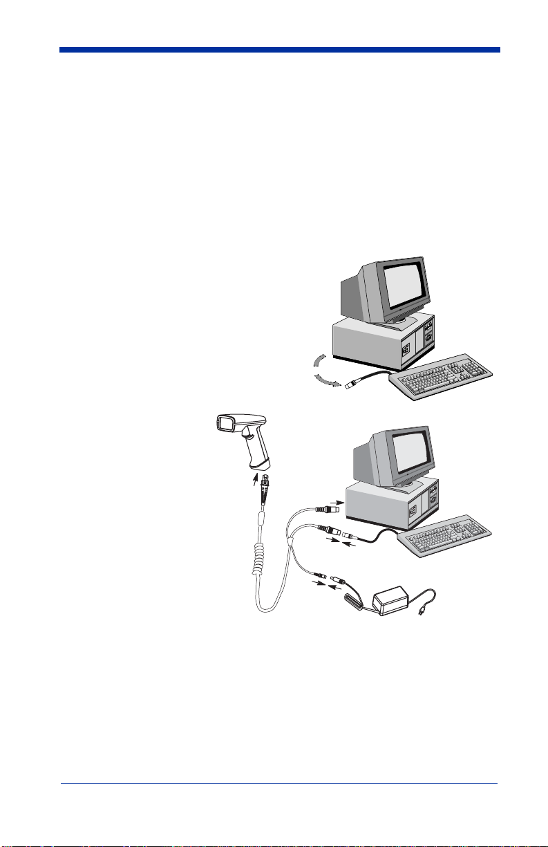
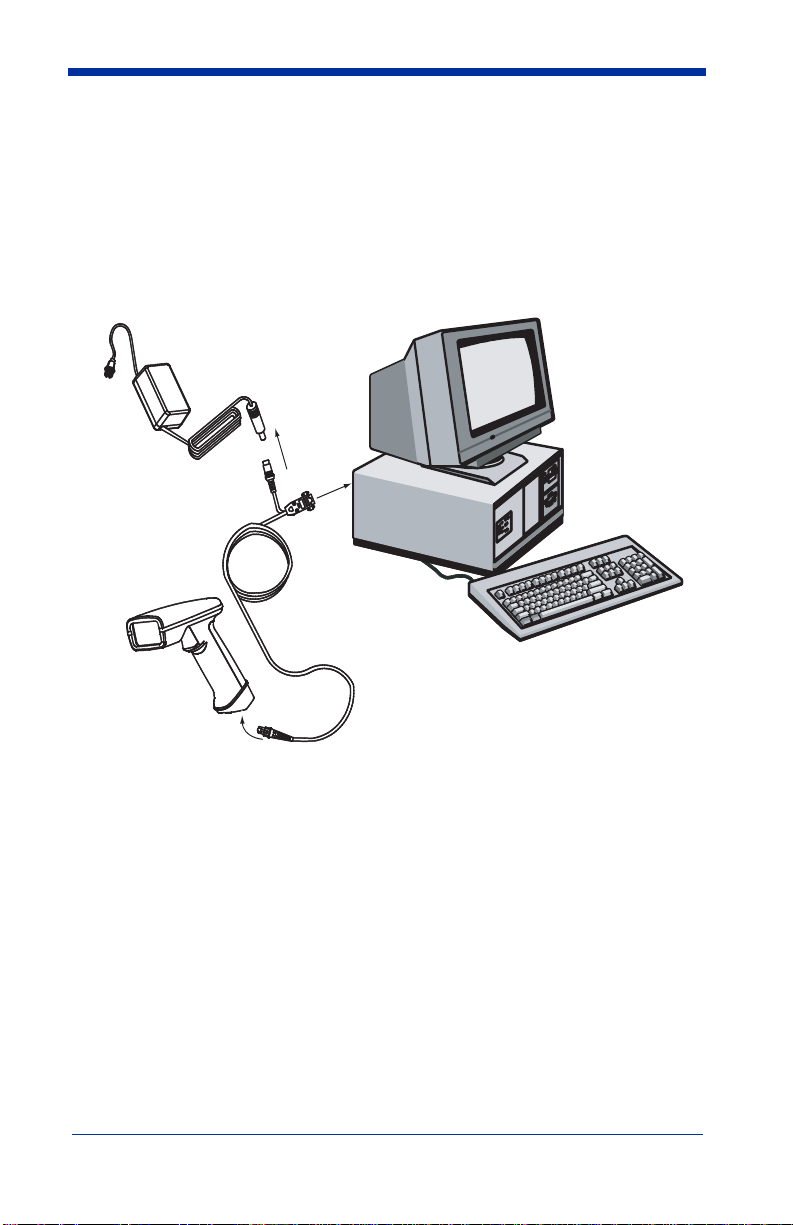
Connecting the Scanner in Keyboard Wedge Mode
A scanner can be connected between the keyboard and PC as a “keyboard
wedge,” plugged into the serial port, or connected to a portable data terminal in
non decoded output mode.
Note: Note: The IMAGETEAM 4410 and 4710 scanners are factory
programmed for a keyboard wedge interface to an IBM PC AT with a USA
keyboard.
The following is an example of a keyboard wedge connection:
1. Turn off power to the terminal/computer.
2. Disconnect the keyboard cable from
the back of the terminal/computer.
Disconnect
3. Connect the
appropriate interface
cable to the scanner
and to the terminal/
computer. The
scanner will beep
twice.
4. Connect the power
supply (4 to 9V).
1
3
5. Turn the terminal/
computer power back
on.
6. Verify the scanner
operation by scanning
a bar code. The
scanner will beep
once.
The scanner is now connected and ready to communicate with your terminal/PC.
You must program the scanner for your interface before bar code data can be
transmitted to your terminal/PC. If you are using the scanner as a keyboard
wedge, see"Terminal Interface" on page 2-4. If the scanner is connected via a
serial port, turn to "Connecting the Scanner to a Serial Port" on page 1-7.
2
4
1 - 6 IMAGETEAM™ 4410/4710 User’s Guide
Page 19
Connecting the Scanner to a Serial Port
Turn off power to the terminal/computer.
1. Connect the interface cable to the scanner
2. Connect the interface cable to the 4 to 9 volt power supply and plug in the
power supply. The scanner will beep twice.
3. Connect the interface cable to the terminal/computer.
2
Power Supply
3
Interface Cable
1
4. Turn the terminal/computer power back on.
5. Verify the scanner operation by scanning a bar code from the sample bar
code section in the back of this manual. The scanner will beep once.
The scanner is now connected and ready to communicate with your terminal/PC.
Turn to "Communication Settings" on page 2-10 to program the communication
parameters for a serial interface.
IMAGETEAM™ 4410/4710 User’s Guide 1 - 7
Page 20
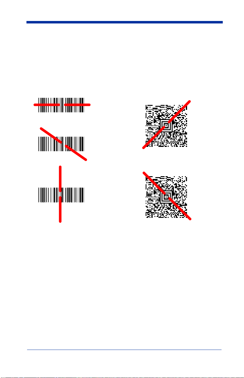
Reading Techniques
The hand-held Imager has a view finder that projects a bright red aiming beam
that corresponds to the Imager’s horizontal field of view. The aiming beam
should be centered over the bar code, but it can be positioned in any direction for
a good read.
Linear bar code 2D Matrix symbol
The aiming beam is smaller when the Imager is closer to the code and larger
when it is farther from the code. Symbologies with smaller bars or elements (mil
size) should be read closer to the unit. Symbologies with larger bars or elements
(mil size) should be read farther from the unit. (see "Depth of Field Charts" on
page 10-4.) To read single or multiple symbols (on a page or on an object), hold
the Imager at an appropriate distance from the target, pull the trigger, and center
the aiming beam on the symbol.
1 - 8 IMAGETEAM™ 4410/4710 User’s Guide
Page 21

2
Programming
Introduction
Use this section to program the hand-held or fixed mount Imager.
This programming section contains the following menuing selections:
• General Selections
• Terminal Interface Selections
• Keyboard Selections
• Communication Settings
• Imager Selections
• Output Selections
• Prefix/Suffix Selections
• Data Formatter Selections
• Output Sequence Selections
IMAGETEAM™ 4410/4710 User’s Guide 2 - 1
Page 22

Reset Factory Settings
All operating parameters are stored in nonvolatile memory resident in the
Imager, where they are permanently retained in the event of a power interruption.
When you receive your Imager, certain operating parameters have already been
set. These are the factory defaults, indicated by the symbol “✱” on the
programming menu pages (beneath the default programming symbol). Default
charts begin on page 5-1.
Default
Status Check
Read the
level to the host terminal. The software revision will be printed out as
“REV_SW:$ProjectRevision:1.xx$;REV_WA:31204960-xxx.”
Read the
Editor formats. One format per line will be printed out.
Show Software
Show Software Revision
Show Data Formats
Revision
symbol to transmit the software revision
symbol to transmit the existing Data Format
Show Data Formats
All Symbologies
If you want to decode all the symbologies allowable for your scanner, scan the
All Symbologies On
All Symbologies
On
code.
All Symbologies
Off
2 - 2 IMAGETEAM™ 4410/4710 User’s Guide
Page 23

Revision Selections
Both the following programming codes would not normally be needed unless you
have a problem with the unit. An Application Support Representative may
request the boot code or power PC revision information in order to trouble shoot
a problem.
Boot Code RevisionPower PC Revision
IMAGETEAM™ 4410/4710 User’s Guide 2 - 3
Page 24

Terminal Interface
IMAGETEAM 4410 and IMAGETEAM 4710 scanners are factory programmed
for a keyboard wedge interface to an IBM PC AT with a USA keyboard. If this is
your interface and you do not need to modify the settings, skip to "Power Saving
Mode" on page 2-16 to begin programming the scanner.
If your interface is not a standard PC AT, refer to the "Supported Terminals
Chart" on page 2-5 and locate the Terminal ID number for your PC. Scan the
Terminal ID bar code below, then scan the numeric bar code(s) on the inside
back cover of this manual to program the scanner for your terminal ID> Scan
Save to save your selection.
For example, an IBM PS/2 terminal has a Terminal ID of 002. You would scan
the Terminal ID bar code, then 0, 0, 2 from the inside back cover, then Save. If
you make an error while scanning the digits (before scanning Save), scan the
Discard code on the back cover and scan the digits and the Save code again.
Note: Factory Default for Keyboard Wedge units = 003
Note: Factory Default for True RS-232 units = 000
Terminal ID Save
2 - 4 IMAGETEAM™ 4410/4710 User’s Guide
Page 25

Supported Terminals Chart
Terminal Model(s)
DEC PC433 SE (Portable PC) 003
DELL Latitude (Portable PC) 003
DTK 486 SLC (Portable PC) 003
Fujitsu Stylistic (Portable PC) 003
HHLC (Code 128 Emulation) 089
IBM PC XT 001
IBM PS/2 25, 30, 77DX2 002
IBM
IBM
IBM
IBM
IBM AT Thinkpad 106
Midwest Micro Elite TS 30 PS (Portable PC) 003
Mitak 4022 (Portable PC) 003
Olivetti M19, M24, M28, M200 001
Olivetti M240, M250, M290, M380, P500 003
Reliasys TR 175 003
RS-232 TTL 000
Televideo 990, 995, 9060 002
Texas Instruments Extensa 560CD (Portable PC) 003
Toshiba 2600 (Portable PC) 003
Toshiba Satellite T1960, T2130, CS (Portable PC) 003
Zenith Z-note (Portable PC) 003
AT, PS/2 30-286, 50, 55SX, 60, 70,
70-061, 70-121, 80
AT Compatibles Keyboard Emulation
(Non-wedge)
Thinkpad 360 CSE, 34, 750
(Portable PC)
Thinkpad 365, 755 CV
(Portable PC)
Terminal
I.D.
003
003
097
003
IMAGETEAM™ 4410/4710 User’s Guide 2 - 5
Page 26

Keyboard Country
Scan the Program Keyboard Country bar code below, then scan the numeric
bar code(s) from the inside back cover, then the Save bar code to program the
keyboard for your country. As a general rule, the following characters are not
supported by the scanner for countries other than the United States:
@ | $ # { } [ ] = / ‘ \ < > ~
Keyboard Country
Country Code Scan Country Code Scan
Belgium..................... 1 Latin America.........14
Czechoslovakia ........ 15 Norway...................9
Denmark................... 8 Poland....................20
Finland......................2 Portugal .................13
France ...................... 3 Romania ................25
French Canadian...... 18 Russia....................26
Germany/Austria....... 4 Slovakia .................22
Great Britain ............. 7 Spain......................10
Greece......................17 Sweden..................23
Netherlands.............. 11 Switzerland ............6
Hungary.................... 19 Turkey Q ................24
Israel.........................12 Turkey F.................27
Italy........................... 5 USA
(Default)
.........0
Save
2 - 6 IMAGETEAM™ 4410/4710 User’s Guide
Page 27

Keyboard Style
This programs keyboard styles, such as Caps Lock and Shift Lock.
Regular.
Regular
Caps Lock
Shift Lock
to U.S. keyboards.)
Automatic Caps Lock
software tracks and reflects if you have Caps Lock on or off (AT and PS/2 only).
This selection can only be used with systems that have an LED which notes the
Caps Lock status.
is used when you normally have the Caps Lock key off.
is used when you normally have the Caps Lock key on.
is used when you normally have the Shift Lock key on. (Not common
is used if you change the Caps Lock key on and off. The
* Regular
Shift Lock
Default =
Caps Lock
Automatic
Caps Lock
Emulate External Keyboard
keyboard (IBM AT or equivalent). To connect to a laptop, you must scan the
Emulate External Keyboard bar code below, then scan "Automatic Direct
Connect Mode On" on page 2-8. After scanning these codes, you must re-boot
your laptop.
should be scanned if you do not have an external
Emulate External
Keyboard
IMAGETEAM™ 4410/4710 User’s Guide 2 - 7
Page 28

Keyboard Modifiers
This modifies special keyboard features, such as CTRL+ ASCII codes and Turbo
Mode.
Control + ASCII Mode On
control characters for values 00-1F. Refer to "Keyboard Function
Relationships" on page 2-9 for CTRL+ ASCII Values.
- The scanner sends key combinations for ASCII
Default = Off
Control + ASCII
Mode On
Turbo Mode
use with IBM AT only.) If the terminal drops characters, do not use Turbo Mode.
Default = Off
Turbo Mode On
Numeric Keypad Mode
numeric keypad.
Numeric Keypad
Mode On
Automatic Direct Connect
keyboard is disabled when you plug in the scanner. This selection can also be
used if you have an IBM AT style terminal and the system is dropping characters.
After scanning these codes, you must re-boot your computer.
- The scanner sends characters to an IBM AT terminal faster. (For
- Sends numeric characters as if entered from a
Default = Off
- Use this selection if you are using a laptop whose
* Control + ASCII
Mode Off
* Turbo Mode Off
* Numeric
Keypad Mode Off
Default = Off
Automatic Direct
Connect Mode On
* Automatic Direct
Connect Mode Off
2 - 8 IMAGETEAM™ 4410/4710 User’s Guide
Page 29

Keyboard Function Relationships
The following Keyboard Function Code, Hex/ASCII Value, and Full ASCII
“CTRL”+ relationships apply to all terminals that can be used with the scanner.
Function Code HEX/ASCII Value Full ASCII “CTRL” +
NUL 00 2
SOH 01 A
STX 02 B
ETX 03 C
EOT 04 D
ENQ 05 E
ACK 06 F
BEL 07 G
BS 08 H
HT 09 I
LF 0A J
VT 0B K
FF 0C L
CR 0D M
SO 0E N
SI 0F O
DLE 10 P
DC1 11 Q
DC2 12 R
DC3 13 S
DC4 14 T
NAK 15 U
SYN 16 V
ETB 17 W
CAN 18 X
EM 19 Y
SUB 1A Z
ESC 1B [
FS 1C \
GS 1D ]
RS 1E 6
US 1F -
IMAGETEAM™ 4410/4710 User’s Guide 2 - 9
Page 30

Communication Settings
<Default All RS-232 Communication Settings>
Parity
Parity provides a means of checking character bit patterns for validity. The
Imager can be configured to operate under
None
) parity options. The host terminal must be set up for the same parity as
(
the Imager, to ensure reliable communication.
Mark, Space, Odd, Even
SpaceMark
, or No
Odd
* None
Even
2 - 10 IMAGETEAM™ 4410/4710 User’s Guide
Page 31

Baud Rate
This sets the baud rate from 300 bits per second to 115,200 bits per second (see
next page). Programming baud rate causes the data to be sent at the specified
rate. The host terminal must be set to the same baud rate as the Imager to
ensure reliable communication.
300 600
1200
19200
2400
96004800
* 38400
IMAGETEAM™ 4410/4710 User’s Guide 2 - 11
Page 32

Baud Rate, continued
57600 115200
Word Length Data Bits
You can set the Word Length at 7 or 8 bits of data per character. If an application
requires only ASCII Hex characters 0 through 7F decimal (text, digits, and
punctuation), select 7 data bits. For applications requiring use of the full ASCII
set, select 8 data bits per character.
7 Data Bits
Word Length Stop Bits
Word Length can be set to one or two stop bits.
* 1 Stop Bit
* 8 Data Bits
2 Stop Bits
2 - 12 IMAGETEAM™ 4410/4710 User’s Guide
Page 33

Hardware Flow Control
When hardware flow control is On, the software checks for a CTS signal before
sending data. This option is useful when your application supports the CTS
signal.
On
* Off
Software Flow Control
This allows control of data transmission from the Imager using software
commands from the host device. When this feature is turned
control is used. When Data Flow Control is turned
transmission by sending the XOFF character (DC3, hex 13) to the Imager. To
resume transmission, the host sends the XON character (DC1, hex 11). Data
transmission continues where it left off when XOFF was sent.
On
On
, the host device suspends
Off
, no data flow
* Off
IMAGETEAM™ 4410/4710 User’s Guide 2 - 13
Page 34

Serial Triggering
This provides a means of sending a serial trigger command to start and stop
decoding. When this feature is turned
trigger commands. When serial triggering is turned
serial trigger character to activate scanning and decoding. The unit continues to
scan and decode until the
occurs, or a bar code is decoded.
On the "Decimal to Hex to ASCII Conversion Chart" on page 2-36, find the hex
characters you want to use to turn the trigger on and off. Locate the decimal
values for those characters and scan the 2 digits for each one from the
Programming Chart in the back of this manual.
When Serial Triggering is On, the default Trigger On decimal character is 18 (hex
12, DC2), and the default Trigger Off decimal character is 20 (hex 14, DC4).
Trigger Off
Off
, the Imager will not respond to serial
character turns off the scanner, a time out
On
, the Imager requires a
* OffOn
Trigger On ‡
* Trigger Defaults
Trigger Off ‡
2 - 14 IMAGETEAM™ 4410/4710 User’s Guide
Page 35

Note: ‡ A one to three digit decimal number and
Save are required after reading this programming symbol. See "Decimal
to Hex to ASCII Conversion Chart" on page 2-36, and the Programming
Chart (inside back cover).
Trigger Timeout
Use this selection to set a timeout (in quarter seconds) of the Imager’s trigger.
Once the imager has timed out, it must be triggered again either serially (see
"Serial Triggering" on page 2-14), or manually. Set the Trigger Timeout to 00 if
you don’t want a Trigger Timeout.
Default setting = 120 seconds
Set Timeout ‡
IMAGETEAM™ 4410/4710 User’s Guide 2 - 15
Page 36

Note: ‡ A one- to three digit number and Save are
required after reading this programming symbol. Refer to the
Programming Chart (inside back cover).
Power Saving Mode
This provides control of the Imager’s power consumption, as follows:
Low Power
read attempt
movement during the read attempt, and powers down after the image capture is
complete.
Medium Power
enhances motion tolerance.
trigger is pulled, going into a “doze” (low power) state after each read attempt.
The Imager powers down ten seconds after the image capture is complete.
Normal Power
trigger is pulled or a decode is in process. The Imager doesn’t go into a “doze”
state after each read attempt, but will power down after two minutes if Power
Hold Mode is turned Off.
draws low (50%) LED current during image capture, allowing one
only
for each trigger pull. The Imager is less tolerant of hand
draws a normal LED current during image capture which
draws a normal LED current, attempting to read as long as the
Low Power Medium Power
Medium Power
attempts to read as long as the
* Normal Power
2 - 16 IMAGETEAM™ 4410/4710 User’s Guide
Page 37

Power Hold Mode
Power Hold On keeps the Imager in a ready to read state. To conserve power,
this selection may be turned
two minutes. When you are ready to use the Imager again, restore power by
pressing the trigger.
On * Off
Off
and the unit will power down if not used within
LED Power Level
This selection allows you to adjust LED brightness.
Off
is used when no illumination is needed.
sufficient.
Off
High
(the default) is the brightest setting.
Low
is used if low illumination is
Low
* High
IMAGETEAM™ 4410/4710 User’s Guide 2 - 17
Page 38

LED Flashing
When LED Flashing is On, the LEDs and aiming light alternately flash until a
symbol is decoded or the trigger is released.
Off
If LED Flashing is turned
aiming light won’t illuminate while the scanner reads a bar code. The LEDs
remain on while the scanner is reading.
Off * On
, the average current draw is increased and the
Aimer Delay
The aimer delay allows a delay time for the operator to aim the scanner before
the picture is taken. Use these codes to set the time between when the trigger
is pulled and when the picture is taken. During the delay time, the aiming light
will appear, but the LEDs won’t turn on until the delay time is over.
200 milliseconds
* Off
(no delay)
400 milliseconds
2 - 18 IMAGETEAM™ 4410/4710 User’s Guide
Page 39

Aimer Interval
Aimer Interval turns off the aiming light, or programs the aimer to come on at
certain intervals when reading symbols with the scanner. You may program the
scanner to use the aimer
Read
. You may also program the scanner to use the aimer every “x” reads, by
entering a number from 0 to 999 to indicate “x.”
Every Read, Every Second Read
, or
Every Third
* Every ReadOff
Every Second Read
Every “x” Reads
Note: ‡ A one- to three digit number and Save are
required after reading this programming symbol. Refer to the
Programming Chart (inside back cover).
‡
Every Third Read
IMAGETEAM™ 4410/4710 User’s Guide 2 - 19
Page 40

Centering
Use the centering feature to narrow the imager’s field of view to make sure that
the imager reads only those bar codes intended by the user. For instance, if
multiple codes are placed closely together, centering will insure that only the
desired codes are read. When centering is turned on, the imager only reads
codes that intersect the centering window set up by the user. The centering
window must intersect the center of the image. If a bar code is not within the
predefined window, it will not be decoded or output by the scanner.
If centering is turned on by scanning the On bar code below, the default centering
window is a 60 pixel square area in the center of the imager’s field of view. The
position of the window may be changed by scanning the top, bottom, left, and
right centering bar codes that follow and the appropriate pixel value, if other than
the default, from the Programming Chart in the back of this manual. The defaults
are listed in the table below.
Window Position Default Minimum Maximum Serial Command
Top of centering
window
Bottom of centering window
Left of centering
window
Right of centering
window
The centering function can be used in conjunction with the Aimer Delay feature
(page 2-18) for the most error-free operation in applications where multiple
codes are spaced closely together. Using the Aimer Delay and Centering
features, the imager can emulate the operation of older systems, such as linear
laser bar code scanners.
210 000 239 DECTPYxxx
270 240 479 DECBTYxxx
290 0 319 DECTPXxxx
350 320 639 DECBTXxxx
* OffOn
The figure below illustrates the default top, bottom, left, and right pixel positions.
The position of the pixels is measured from the top and the left side of the
2 - 20 IMAGETEAM™ 4410/4710 User’s Guide
Page 41

imager’s field of view with the field of view being 640 by 480 pixels.
290 350
0
Top
210
640
270
480
Left
Right
Bottom
Default
Center
IMAGETEAM™ 4410/4710 User’s Guide 2 - 21
Page 42

Top of Centering
Window
Top of Centering Window
Default (210)
Bottom of Centering
Window
Left of Centering
Window
Right of Centering
Window
Bottom of Centering
Window Default (270)
Left of Centering
Window Default (290)
Right of Centering
Window Default (350)
2 - 22 IMAGETEAM™ 4410/4710 User’s Guide
Page 43

In the example below, the gray area is the full imager field of view and the white
area is the centering window. Bar Code 1 will not be read, while Bar Code 2 will
be.
Bar Code 1
Bar Code 2
AutoTrigger
Two AutoTrigger Modes are available: Scan Stand and Presentation Mode.
When a unit is in Scan Stand mode, it remains idle as long as it sees the Scan
Stand symbol. (See Scan Stand Symbol that follows.) When a different code is
presented, the Imager is triggered to read the new code.
Note: The scanner automatically adjusts the illumination LEDs to the lowest
light level possible to maintain a good lock on the Scan Stand symbol.
Presentation mode is for those applications where a scan stand will not work, i.e.,
when large packages must be scanned. To program the device for presentation
mode, refer to "Presentation Mode" on page 2-24.
Scan Stand
This selection programs the Imager to work in a Scan Stand.
On* Off
IMAGETEAM™ 4410/4710 User’s Guide 2 - 23
Page 44

Scan Stand Symbol
Note: Scan Stand mode does not work when scanner is programmed for the
HHLC interface.
When a unit is in Scan Stand mode, the LEDs shine at the Scan Stand symbol
on the base of the stand which tells it to remain idle. When the Scan Stand
symbol is covered, the imager turns the LEDs on at the configured power level
(Default High) and attempts to find and decode bar codes in its field of view.
Scan Stand
Symbol
Presentation Mode
Note: Presentation Mode does not work when scanner is programmed for the
HHLC interface.
This programs the scanner to work in Presentation Mode.
On* Off
Presentation Re-trigger Delay
This sets the time period before the scanner can re-trigger for another read
attempt. Setting a re-trigger delay protects against accidental rereads of the
same bar code. Longer delays are effective in minimizing accidental rereads at
POS (point of sale). Use shorter delays in applications where repetitive bar code
scanning is required. Entries are in milliseconds, from 1 to 10,000. Scan the
Presentation Re-trigger Delay bar code below, then scan the number of
milliseconds and the Save bar code from the inside back cover.
Default = 200.
Presentation Re-trigger Delay
2 - 24 IMAGETEAM™ 4410/4710 User’s Guide
Page 45

Presentation Lights
When using the scanner in presentation mode, the illuminating LEDs can be
programmed on or off. If there is sufficient ambient light, the LEDs can be turned
off by scanning the Lights Off bar code below. When a bar code is presented to
the scanner, the illuminating LEDs turn on to scan the bar code and then turn off
when the bar code has been read.
Default = Presentation Mode Lights On
.
* On
Presentation Default
Defaults all presentation mode settings.
Presentation Reread Delay 200 ms.
Presentation Default
Defaults
Off
=
Presentation Mode Off,
IMAGETEAM™ 4410/4710 User’s Guide 2 - 25
Page 46

Fast Omni Mode
Normally, the imager searches throughout its whole field of view to determine if
a bar code is present. Fast omni-directional mode provides a reduced search
pattern that increases the scan rate of the imager. When fast omni mode is
enabled, the imager only tries to locate bar codes in the center area of the image.
Consequently, the user is required to center the aiming line over the bar code he
wants to read. When a portion of the bar code is in the center area of the image,
the imager locates and decodes the bar code. The entire bar code does not need
to be in the center area, only a portion of it. Bar codes that are not in the center
area of the image will not be found.
Note: Fast Omni Mode is not recommended when scanning Data Matrix codes.
* Normal, Full
Search Mode
Beeper Volume
Off
Medium
Reduced Omni-
directional Mode
Low
* High
2 - 26 IMAGETEAM™ 4410/4710 User’s Guide
Page 47

Power Up Beeper
* On
Off
Output Sequence Beeper
If you are using an Output Sequence (see "Output Sequence Overview" on page
2-43), you may want to hear a beep after each bar code as it is read. Scan
Output Sequence Beeper
* On
On
to enable this feature, or
Off
to disable it.
Off
Beep On Decode
If you want the scanner to beep each time it reads a bar code, leave this setting
On
. If you don’t want it to beep on each read, but do want it to beep for other
events, such as error conditions, set this selection to
* On
Off
.
Off
Beeper Default
Defaults all beeper settings.
On, Output Sequence Beeper On, Beep On Read On.
IMAGETEAM™ 4410/4710 User’s Guide 2 - 27
Defaults
=
Beeper Default
Beeper Volume High, Power Up Beeper
Page 48

Intercharacter, Interfunction, and Intermessage Delays
Some terminals drop information (characters) if data comes through too quickly.
Intercharacter, interfunction, and intermessage delays slow the transmission of
data increasing data integrity.
Each delay is composed of a 5 millisecond step. You can program up to 99 steps
(of 5 ms each).
Intercharacter Delay
Note: This selection is valid for keyboard wedge interfaces only.
This is a delay of up to 495 milliseconds (in multiples of 5) placed between the
transmission of each character of scanned data. You can program up to 99 steps
(of 5 ms each). Scan the
number of steps, and the
Note:
If you make an error while scanning the digits (before scanning Save),
scan
Discard
again.
Intercharacter Delay
Save
bar code from the inside back cover.
on the back cover and scan the correct digits and
Prefix Scanned Data Suffix
1 2345
Intercharacter Delay
bar code below, then scan the
Save
Intercharacter Delay
To remove this delay, scan the
number of steps to 00. Scan the
Intercharacter Delay
Save
bar code from the inside back cover.
bar code, then set the
User Specified Intercharacter Delay
Note: This selection is valid for keyboard wedge interfaces only.
This is a delay of up to 495 milliseconds (in multiples of 5) placed after the
transmission of a particular character of scanned data. You can program up to
99 steps (of 5 ms each) to follow the character you specify. Scan the
bar code below, then scan the number of steps for the delay, and the
Length
Save
bar code from the inside back cover.
2 - 28 IMAGETEAM™ 4410/4710 User’s Guide
Delay
Page 49

Next, scan the
ASCII character that trigger the delay (refer to the "Decimal to Hex to
ASCII Conversion Chart" on page 2-36).
scanning the digits (before scanning Save), scan
cover and scan the correct digits and
Character to Trigger
bar code, then the 2 digit hex value for the
Note:
If you make an error while
Discard
Save
again.
on the back
Delay Length
To remove this delay, scan the
steps to 00. Scan the
Save
bar code from the inside back cover.
Delay Length
Character to Trigger Delay
bar code, then set the number of
Interfunction Delay
Note: This selection is valid for keyboard wedge interfaces only.
This is a delay of up to 495 milliseconds (in multiples of 5) placed between the
transmission of each segment of the message string. You can program up to 99
steps (of 5 ms each). Scan the
the number of steps, and the
Note: If you make an error while scanning the digits (before scanning Save),
scan Discard on the back cover and scan the correct digits and Save
again.
Interfunction Delay
Save
bar code from the inside back cover.
Prefix Scanned Data Suffix
1 2345STX HT CR LF
Interfunction Delays
Interfunction Delay
bar code below, then scan
To remove this delay, scan the
number of steps to 00. Scan the
Interfunction Delay
Save
bar code from the inside back cover.
bar code, then set the
IMAGETEAM™ 4410/4710 User’s Guide 2 - 29
Page 50

Intermessage Delay
Note: This selection is valid for keyboard wedge interfaces only.
This is a delay of up to 495 milliseconds (in multiples of 5) placed between each
scan transmission. You can program up to 99 steps (of 5 ms each). Scan the
Intermessage Delay
Save
bar code from the inside back cover.
Note:
If you make an error while scanning the digits (before scanning Save),
scan
Discard
again.
bar code below, then scan the number of steps, and the
on the back cover and scan the correct digits and
2nd Scan Transmission1st Scan Transmission
Intermessage Delay
Intermessage Delay
Save
To remove this delay, scan the
number of steps to 00. Scan the
Intermessage Delay
Save
bar code from the inside back cover.
bar code, then set the
2 - 30 IMAGETEAM™ 4410/4710 User’s Guide
Page 51

Prefix/Suffix Overview
When a bar code is scanned, additional information is sent to the host computer
along with the bar code data. This group of bar code data and additional,
user-defined data is called a “message string.” The selections in this section are
used to build the user-defined data into the message string.
Prefix and Suffix characters are data characters that can be sent before and after
scanned data. You can specify if they should be sent with all symbologies, or
only with specific symbologies. The following illustration shows the breakdown
of a message string:
Prefix Scanned Data Suffix
1-10
alpha
numeric
characters
variable
length
1-10
alpha
numeric
characters
Points to Keep In Mind
• It is not necessary to build a message string. The selections in this chapter
are only used if you wish to alter the default settings.
Default suffix = CR/LF
• A prefix or suffix may be added or cleared from one symbology or all
symbologies.
• You can add any prefix or suffix from the "Decimal to Hex to ASCII
Conversion Chart" on page 2-36, plus Code I.D. and Aim I.D.
• You can string together several entries for several symbologies at one time.
• Enter prefixes and suffixes in the order in which you want them to appear on
the output.
.
Default prefix = None.
IMAGETEAM™ 4410/4710 User’s Guide 2 - 31
Page 52

Adding a Prefix or Suffix
1. Scan the
2. Determine the 2 digit Hex value from the "Symbology Chart" on page 2-35
for the symbology to which you want to apply the prefix or suffix.
3. Scan the 2 hex digits from the Programming Chart inside the back cover or
scan
4. Determine the hex value from the "Decimal to Hex to ASCII Conversion
Chart" on page 2-36 for the prefix or suffix you wish to enter.
5. Scan the 2 digit hex value from the Programming Chart inside the back
cover.
Note:
Note:
6. Scan Save to exit and save, or scan Discard to exit without saving.
Repeat Steps 1-6 to add a prefix or suffix for another symbology.
Example: Add a Suffix to a specific symbology
To send a CR (carriage return)Suffix for UPC only:
1. Scan
2. Determine the 2 digit hex value from the "Symbology Chart" on page 2-35 for
UPC.
3. Scan
4. Determine the hex value from the "Decimal to Hex to ASCII Conversion
Chart" on page 2-36 for the CR (carriage return).
5. Scan
6. Scan
Add Prefix
9, 9
for all symbologies.
Repeat Steps 4 and 5 for every prefix or suffix character.
To add the Code I.D., scan
To add AIM I.D., scan
To add a backslash (\), scan
Add Suffix
6, 3
from the Programming Chart (inside back cover).
0, D
from the Programming Chart (inside back cover).
Save
, or scan
(page 2-34) or
5, C, 8, 1
.
Discard
Add Suffix
5, C, 8, 0
.
symbol (page 2-34).
.
5, C, 5, C.
to exit without saving.
Clearing One or All Prefixes or Suffixes
You can clear a single prefix or suffix, or clear all prefixes/suffixes for a
symbology. When you Clear One Prefix (Suffix), the specific character you
select is deleted from the symbology you want. When you Clear All Prefixes
(Suffixes), all the prefixes or suffixes for a symbology are deleted.
1. Scan the
2. Determine the 2 digit Hex value from the "Symbology Chart" on page 2-35
for the symbology from which you want to clear the prefix or suffix.
3. Scan the 2 digit hex value from the Programming Chart inside the back cover
or scan
Your change is automatically saved.
Clear One Prefix
9, 9
for all symbologies.
2 - 32 IMAGETEAM™ 4410/4710 User’s Guide
symbol.
Page 53

Add a Carriage Return Suffix to All Symbologies
Scan the following bar code if you wish to add a Carriage Return/Line Feed Suffix
to all symbologies at once. This action first clears all current suffixes, then
programs a carriage return suffix for all symbologies.
Add CR/LF Suffix
All Symbologies
Add a Code I.D. Prefix to All Symbologies
This selection allows you to turn on (or off) transmission of a Code I.D. before the
decoded symbology. (See the "Symbology Chart" on page 2-35 for the single
character code that identifies each symbology.) This action first clears all current
prefixes, then programs a Code I.D. prefix for all symbologies.
Add Code ID Prefix
All Symbologies
Add an AIM I.D. Prefix to All Symbologies
This selection allows you to turn on (or off) transmission of an AIM I.D. before the
decoded symbology. (See the "Symbology Chart" on page 2-35 for the single
character code that identifies each symbology.) This action first clears all current
prefixes, then programs an AIM I.D. prefix for all symbologies.
Add AIM ID Prefix
All Symbologies
(See AIM Guidelines on Symbology Identifiers for more information on the AIM
symbology ID characters.)
IMAGETEAM™ 4410/4710 User’s Guide 2 - 33
Page 54

Prefix Entries
Add Prefix †
Suffix Entries
Add Suffix †
Clear One Prefix †
Clear All Prefixes
Clear One
Suffix †
Clear All Suffixes
† One or more two digit numbers and
programming symbol. Refer to the Programming Chart (inside back cover).
Save
are required after reading this
Exit Selections
Save Discard
2 - 34 IMAGETEAM™ 4410/4710 User’s Guide
Page 55

Symbology Chart
Symbology
Australian 4 State
Aztec Code
BC412**
BPO 4 State
Canadian 4 State
Codabar
Codablock-F
Code 11
Code 39
Code 49
Code 93
Code 128
Code Z**
Data Matrix
EAN
IATA 2 of 5
CodeIDAIMIDHex
ID
A]X41
z]z7A
g]X67
B]X42
C]X43
a]F61
q]O71
h]H068
b]A62
l]T6C
i]G69
j]C6A
u]X75
w]d77
d]E64
f]R66
Symbology
Interleaved 2 of 5
Japanese Postal
Kix (Dutch) Postal
Maxicode
Micro PDF417
MSI
No Read
OCR
PDF417
Planet Code
Postnet
QR Code
RSS/Composites
UPC
Vericode**
All Symbologies
CodeIDAIMIDHex
e]l65
J]X4A
K]X4B
x]U78
R]L52
g]M067
o]Y6F
r]L72
L]X4C
P]X50
s]Q73
y]e79
c]E63
v]V76
†
ID
9C
99
Note: Prefix/Suffix entries for specific symbologies override the universal (All
Symbologies, 99) entry.
Note:† All Symbologies: Prefix/Suffix programming only!
Note: ** Not available in standard product. Only available when ordered in
custom firmware
IMAGETEAM™ 4410/4710 User’s Guide 2 - 35
Page 56

Decimal to Hex to ASCII Conversion Chart
Dec. Hex ASCII Dec. Hex ASCII Dec. Hex ASCII Dec. Hex ASCII
0 00 NUL 32 20 SP 64 40 @ 96 60 ‘
1 01 SOH 33 21 ! 65 41 A 97 61 a
2 02 STX 34 22 “ 66 42 B 98 62 b
3 03 ETX 35 23 # 67 43 C 99 63 c
4 04 EOT 36 24 $ 68 44 D 100 64 d
5 05 ENQ 37 25 % 69 45 E 101 65 e
6 06 ACK 38 26 & 70 46 F 102 66 f
7 07 BEL 39 27 ‘ 71 47 G 103 67 g
8 08 BS 40 28 ( 72 48 H 104 68 h
9 09 HT 41 29 ) 73 49 l 105 69 i
10 0A LF 42 2A * 74 4A J 106 6A j
11 0B VT 43 2B + 75 4B K 107 6B k
12 0C FF 44 2C , 76 4C L 108 6C l
13 0D CR 45 2D - 77 4D M 109 6D m
14 0E SO 46 2E . 78 4E N 110 6E n
15 0F SI 47 2F / 79 4F O 111 6F o
16 10 DLE 48 30 0 80 50 P 112 70 p
17 11 DC1 49 31 1 81 51 Q 113 71 q
18 12 DC2 50 32 2 82 52 R 114 72 r
19 13 DC3 51 33 3 83 53 S 115 73 s
20 14 DC4 52 34 4 84 54 T 116 74 t
21 15 NAK 53 35 5 85 55 U 117 75 u
22 16 SYN 54 36 6 86 56 V 118 76 v
23 17 ETB 55 37 7 87 57 W 119 77 w
24 18 CAN 56 38 8 88 58 X 120 78 x
25 19 EM 57 39 9 89 59 Y 121 79 y
26 1A SUB 58 3A : 90 5A Z 122 7A z
27 1B ESC 59 3B ; 91 5B [ 123 7B {
28 1C FS 60 3C < 92 5C \ 124 7C |
29 1D GS 61 3D = 93 5D ] 125 7D }
30 1E RS 62 3E > 94 5E ^ 126 7E ~
31 1F US 63 3F ? 95 5F _ 127 7F DEL
2 - 36 IMAGETEAM™ 4410/4710 User’s Guide
Page 57

Data Format Editor Overview
The Data Format Editor selections are used to edit scanned data. For example,
you can use the Data Format Editor to insert characters at certain points in bar
code data as it is scanned.
It is not necessary to use the Data Format Editor. A set of defaults for the data
format is already programmed in the scanner. The selections in the following
pages are used only if you wish to alter the default settings.
setting = none.
If you have changed data format settings, and wish to clear all formats and return
to the defaults, scan the Default Data Format code.
To Add a Data Format
1. Scan the
2. Primary/Alternate Format
Determine if this will be your primary data format, or one of 3 alternate
formats. (Alternate formats allow you “single shot” capability to scan one bar
code using a different data format. After the one bar code has been read,
the scanner reverts to the primary data format. See "Alternate Data
Formats" on page 2-42.) If you are programming the primary format, scan 0.
If you are programming an alternate format, scan
the alternate format you are programming.
3. Terminal Type
Refer to the "Supported Terminals Chart" on page 2-5 and locate the
Terminal ID number for your PC. Scan three numeric bar codes on the
inside back cover to program the scanner for your terminal ID (you must
enter 3 digits). For example, scan
Enter Data Format
symbol (page 2-40).
0 0 3
for an AT wedge.
Note: The wildcard for all terminal types is 099.
Default Data Format
1, 2
, or 3, depending on
4. Code I.D.
On page 2-35, find the symbology to which you want to apply the data
format. Locate the Hex value for that symbology and scan the 2 digit hex
value from the Programming Chart.
5. Length
Specify what length (up to 9999 characters) of data will be acceptable for this
symbology. Scan the four digit data length from the Programming Chart.
(Note: 50 characters is entered as 0050. 9999 is a universal number,
indicating all lengths.)
6. Editor Commands
Refer to the "Format Editor Commands" on page 2-38. Scan the symbols
that represent the command you want to enter. 94 alphanumeric characters
may be entered for each symbology data format.
7. Scan
Save
to save your entries.
IMAGETEAM™ 4410/4710 User’s Guide 2 - 37
Page 58

Other Programming Selections
• Clear One Data Format
This deletes one data format for one symbology. If you are clearing the
primary format, scan 0. If you are clearing an alternate format, scan 1, 2, or
3, depending on the alternate format you are clearing. Scan the Terminal
Type (refer to the "Supported Terminals Chart" on page 2-5), Code I.D. and
the length of the format you want to delete. That length data format for that
symbology is deleted and all other formats are unaffected.
• Save
This exits, saving any Data Format changes.
• Discard
This exits without saving any Data Format changes.
Format Editor Commands
Send Commands
F1 Send all characters followed by “xx” key or function code, starting from
current cursor position.
ASCII code, see "Decimal to Hex to ASCII Conversion Chart" on page 2-
36.)
F2 Send “nn” characters followed by “xx” key or function code, starting from
current cursor position.
value (00-99) for the number of characters and xx stands for the hex value
for an ASCII code. See "Decimal to Hex to ASCII Conversion Chart" on
page 2-36.)
F3 Send up to but not including “ss” character (Search and Send) starting
from current cursor position, leaving cursor pointing to “ss” character
followed by “xx” key or function code.
stand for the hex values for ASCII codes, see "Decimal to Hex to ASCII
Conversion Chart" on page 2-36.)
F4 Send “xx” character “nn” times (Insert) leaving cursor in current cursor
position.
see "Decimal to Hex to ASCII Conversion Chart" on page 2-36, and nn is
the numeric value (00-99) for the number of times it should be sent.)
E9 Send all but the last “nn” characters, starting from the current cursor
position.
of characters that will not be sent at the end of the message.)
Move Commands
F5 Move the cursor ahead “nn” characters from current cursor position.
Syntax = F4xxnn
Syntax = E9nn
Syntax = F5nn
of characters the cursor should be moved ahead.)
F6 Move the cursor back “nn” characters from current cursor position.
Syntax = F6nn
of characters the cursor should be moved back.)
F7 Move the cursor to the beginning of the data string.
EA Move the cursor to the end of the data string.
Syntax = F1xx
Syntax = F2nnxx
(xx stands for the hex value for an ASCII code,
(nn is the numeric value (00-99) for the number
(nn stands for the numeric value (00-99) for the number
(nn stands for the numeric value (00-99) for the number
(xx stands for the hex value for an
(nn stands for the numeric
Syntax = F3ssxx
(ss and xx both
Syntax = F7.
Syntax = EA
2 - 38 IMAGETEAM™ 4410/4710 User’s Guide
Page 59

Search Commands
F8 Search ahead for “xx” character from current cursor position, leaving
cursor pointing to “xx” character.
Syntax = F8xx
(xx stands for the hex
value for an ASCII code, see "Decimal to Hex to ASCII Conversion
Chart" on page 2-36.)
F9 Search back for “xx” character from current cursor position, leaving cursor
pointing to “xx” character.
Syntax = F9xx
(xx stands for the hex value for
an ASCII code, see "Decimal to Hex to ASCII Conversion Chart" on page
2-36.)
E6 Search ahead for the first non “xx” character from the current cursor
position, leaving cursor pointing to non ”xx” character.
Syntax = E6xx
stands for the hex value for an ASCII code, see "Decimal to Hex to ASCII
Conversion Chart" on page 2-36.)
E7 Search back for the first non “xx” character from the current cursor
position, leaving cursor pointing to non ”xx” character.
Syntax = E7xx
stands for the hex value for an ASCII code, see "Decimal to Hex to ASCII
Conversion Chart" on page 2-36.)
Miscellaneous Commands
FB Suppress all occurrences of up to 15 different characters, starting at the
current cursor position, as the cursor is advanced by other commands.
When the FC command is encountered, the suppress function is
terminated. The cursor is not moved by the FB command. Syntax =
FBnnxxyy . .zz where nn is a count of the number suppress characters in
the list and xxyy .. zz is the list of characters to be suppressed. (xx stands
for the hex value for an ASCII code, see "Decimal to Hex to ASCII
Conversion Chart" on page 2-36.)
FC Disable suppress filter and clear all suppressed characters.
Syntax = FC.
E4 Replaces up to 15 characters in the data string with user specified
characters. Replacement continues until the E5 command is
encountered.
Syntax = E4nnxx1xx2yy1yy2...zz1zz
where nn is the total
2
count of both characters to be replaced plus replacement characters; xx
defines characters to be replaced and xx
characters, continuing through zz
1
E5 Terminates character replacement.
defines replacement
2
and zz2.
Syntax = E5.
FE Compare character in current cursor position to the character “xx.” If
characters are equal, increment cursor. If characters are not equal, no
format match.
Syntax = FExx
(xx stands for the hex value for an ASCII
code, see "Decimal to Hex to ASCII Conversion Chart" on page 2-36.)
EC Check to make sure there is an ASCII number at the current cursor
position. If character is not numeric, format is aborted.
Syntax = EC
ED Check to make sure there is a non-numeric ASCII character at the current
cursor position. If character is numeric, format is aborted.
Syntax = ED
(xx
(xx
.
1
.
IMAGETEAM™ 4410/4710 User’s Guide 2 - 39
Page 60

Data Format Editor
See page 2-37 through page 2-39 for a description of Data Format selections and
commands.
Enter Data Format † Default
Clear One
Data Format †
Data Format
(none)
Clear All
Data Formats
Exit Selections
Save Current
Data Format Changes
Discard Current
Data Format Changes
† One or more two digit numbers and
programming symbol. Refer to the Programming Chart (inside back cover).
Save
are required after reading this
2 - 40 IMAGETEAM™ 4410/4710 User’s Guide
Page 61

Data Formatter
When Data Formatter is turned off, the bar code data is output to the host as read
(including prefixes and suffixes).
* On/Not Required Off
Require Data Format
When Data Formatter is
format or the scanner does not transmit the input data to the host device.
Required
, all input data must conform to an edited
Required
Show Data Formats
Read the
One format per line is printed out.
Show Data Formats
bar code to transmit the existing data formats.
Show Data Formats
IMAGETEAM™ 4410/4710 User’s Guide 2 - 41
Page 62

Alternate Data Formats
Alternate formats allow you “single shot” capability to scan one bar code using a
different data format than your primary format. When data formats are
programmed (see page 2-37), you must input whether you are programming the
primary format, or an alternate format numbered 1, 2, or 3.
An alternate format is initiated by scanning one of the 3 alternate format bar
codes below. The scanner will scan the next bar code, formatting the data with
the selected alternate format, then revert immediately to the primary format.
Alternate
Data Format 1
Alternate
Data Format 2
Alternate Data Format 3
2 - 42 IMAGETEAM™ 4410/4710 User’s Guide
Page 63

Output Sequence Overview
Output Sequence Editor
This programming selection allows you to program the Imager to output data
(when scanning more than one symbol) in whatever order your application
requires, regardless of the order in which the bar codes are scanned. Reading
Default Sequence
the
shown below. These are the defaults. Be certain you want to delete or clear all
formats before you read the
Note: To make Output Sequence Editor selections, you’ll need to know the code
I.D., code length, and character match(es) your application requires. Use
the Alphanumeric symbols (inside back cover) to read these options.
To Add an Output Sequence
1. Scan the
2-46).
2. Code I.D.
On the "Symbology Chart" on page 2-35, find the symbology to which you
want to apply the output sequence format. Locate the Hex value for that
symbology and scan the 2 digit hex value from the Programming Chart
(inside back cover).
3. Length
Specify what length (up to 9999 characters) of data output will be acceptable
for this symbology. Scan the four digit data length from the Programming
Chart. (Note: 50 characters is entered as 0050. 9999 is a universal number, indicating all lengths.)
4. Character Match Sequences
On the "Decimal to Hex to ASCII Conversion Chart" on page 2-36, find the
Hex value that represents the character(s) you want to match. Use the Programming Chart to read the alphanumeric combination that represents the
ASCII characters. (99 is the Universal number, indicating all characters.)
5. End Output Sequence Editor
Scan
Current Output Sequence Changes
Other Programming Selections
•
Discard Current Output Sequence Changes
This exits without saving any Output Sequence changes.
Enter Sequence
F F
to enter an Output Sequence for an additional symbology, or
symbol programs the Imager to the Universal values,
Default Sequence
symbol (see "Output Sequence Editor" on page
symbol.
Save
to save your entries.
Output Sequence Example
In this example, you are scanning Code 93, Code 128, and Code 39 bar codes,
but you want the scanner to output Code 39 1st, Code 128 2nd, and Code 93
3rd, as shown below.
IMAGETEAM™ 4410/4710 User’s Guide 2 - 43
Page 64

Note: Code 93 must be enabled to use this example.
A - Code 39
B - Code 128
C - Code 93
You would set up the sequence editor with the following command line:
SEQBLK62999941FF6A999942FF69999943FF
The breakdown of the command line is shown below:
SEQBLKsequence editor start command
62 code identifier for Code 39
9999code length that must match for Code 39, 9999 = all lengths
41 start character match for Code 39, 41h = “A”
FF termination string for first code
6A code identifier for Code 128
9999code length that must match for Code 128, 9999 = all lengths
42 start character match for Code 128, 42h = “B”
FF termination string for second code
69 code identifier for Code 93
9999code length that must match for Code 93, 9999 = all lengths
43 start character match for Code 93, 43h = “C”
FF termination string for third code
Require Output Sequence
When an output sequence is
sequence or the scanner will not transmit the output data to the host device.
When it’s
conform to an edited sequence, but if it cannot, the scanner transmits all output
data to the host device as is.
On/Not Required
2 - 44 IMAGETEAM™ 4410/4710 User’s Guide
Required
, the scanner will attempt to get the output data to
, all output data must conform to an edited
Page 65

When the output sequence is
scanner decodes it.
Off
, the bar code data is output to the host as the
Note: This selection is unavailable when the Multiple Symbols Selection is
turned on.
Required On/Not Required
Off
IMAGETEAM™ 4410/4710 User’s Guide 2 - 45
Page 66

Output Sequence Editor
Enter Sequence † Default Sequence
Exit Selections
Save Current
Output Sequence Changes
Discard Current
Output Sequence Changes
Note: If you want the scanner to beep after each bar code is read, please see
"Output Sequence Beeper" on page 2-27.
† One or more two digit numbers and Save are required after reading this
programming symbol. Refer to the Programming Chart (inside back cover).
2 - 46 IMAGETEAM™ 4410/4710 User’s Guide
Page 67

Multiple Symbols
Note: This feature does not work when the Imager is in Low Power mode.
When this programming selection is turned On, it allows you to read multiple
symbols with a single pull of the Imager’s trigger. If you press and hold the
trigger, aiming the Imager at a series of symbols, it reads unique symbols once,
beeping (if turned on) for each read. Data is output as the imager finds and
decodes the symbols. The imager attempts to find and decode new symbols as
long as the trigger is pulled. When this programming selection is turned
Imager will only read the symbol closest to the aiming beam.
Off
, the
On
* Off
No Read
With No Read turned On, the Imager notifies you if a code cannot be read. In
the Quick*View Scan Data Window (see "Scan Data Window" on page 7-4), an
“NR” appears when a code cannot be read. If No Read is turned
will not appear.
On
If you want a different notation than “NR,” for example, “Error,” or “Bad Code,”
you can edit the output message using the Data Formatter (see page 2-37). The
hex code for the No Read symbol is 9C.
Off
, the “NR”
* Off
IMAGETEAM™ 4410/4710 User’s Guide 2 - 47
Page 68

Print Weight
Print Weight is used to adjust the way the scanner reads Matrix symbols. If a
scanner will be seeing consistently heavily printed matrix symbols, then a print
weight of 6 may improve the reading performance. For consistently light printing,
a print weight of 2 may help. A value from 0 to 7 may be used to adjust the print
weight. The default print weight is 4.
† Set Print Weight
† A one digit number from 1 to 7 is required after reading this programming
symbol. Refer to the Programming Chart (inside back cover).
* Default
Function Code Transmit
When this selection is enabled and function codes are contained within the
scanned data, the scanner transmits the function code to the terminal. Charts of
these function codes are provided in Chapter 9, Supported Interface Keys.
When the scanner is in keyboard wedge mode, the scan code is converted to a
key code before it is transmitted.
* On
Off
2 - 48 IMAGETEAM™ 4410/4710 User’s Guide
Page 69

Video Reverse
Video Reverse is used to allow the imager to read bar codes that are inverted.
The “Off” bar code below is an example of this type of bar code. If additional
menuing is required, Video Reverse must be disabled to read the menu bar
codes and then re-enabled after menuing is completed.
Note: Images downloaded from the unit will not be reversed. This is a setting
for decoding only.
On
* Off
IMAGETEAM™ 4410/4710 User’s Guide 2 - 49
Page 70

2 - 50 IMAGETEAM™ 4410/4710 User’s Guide
Page 71

3
Symbologies
Introduction
Use this section to program the hand-held Imager.
This programming section contains the following menuing selections:
• Linear Symbology Selections
• Stacked Symbology Selections
• Postal Symbology Selections
• 2D Matrix Symbology Selections
• Diagnostics
IMAGETEAM™ 4410/4710 User’s Guide 3 - 1
Page 72

Linear Symbologies
Codabar
<Default All Codabar Settings>
Codabar
* On
Off
Start/Stop Characters
Start/Stop characters identify the leading and trailing ends of the bar code. You
may either transmit, or not transmit Start/Stop characters.
Start/Stop Transmit
* Don’t Transmit
Start/Stop
Message Length
The message length selection is used to set the valid reading length of the bar
code. If the data length of the scanned bar code doesn’t match the valid reading
length, the scanner will not read the symbol. You may wish to set the same value
for minimum and maximum length to force the scanner to read fixed length bar
code data. This helps reduce the chances of a misread.
3 - 2 IMAGETEAM™ 4410/4710 User’s Guide
Page 73

Linear Symbologies
EXAMPLE:Decode only those bar codes with a count of 9-20 characters.
EXAMPLE:Decode only those bar codes with a count of 15 characters.
Min. length = 09 Max. length = 20
Min. length = 15 Max. length = 15
Minimum
Message Length
Save
The desired message length and
programming symbol. Refer to the Programming Chart (inside back cover).
must be input after reading this
Maximum
Message Length
Codabar, continued
Check Character
No Check Character
data with or without a check character.
When Check Character is set to
read Codabar bar codes printed with a check character, but will not transmit the
check character with the scanned data.
When Check Character is set to
read Codabar bar codes printed with a check character, and will transmit this
character at the end of the scanned data.
indicates that the scanner reads and transmits bar code
Validate, But Don’t Transmit
Validate, And Transmit
* No Check Character
, the unit will only
, the scanner will only
Validate,
But Don’t Transmit
Validate,
And Transmit
IMAGETEAM™ 4410/4710 User’s Guide 3 - 3
Page 74

Linear Symbologies
Code 39
< Default All Code 39 Settings >
Code 39
* On Off
Start/Stop Characters
Start/Stop characters identify the leading and trailing ends of the bar code. You
may either transmit, or not transmit Start/Stop characters.
Transmit
3 - 4 IMAGETEAM™ 4410/4710 User’s Guide
* Don’t Transmit
Page 75

Linear Symbologies
Message Length
The message length selection is used to set the valid reading length of the bar
code. If the data length of the scanned bar code doesn’t match the valid reading
length, the scanner will not read the symbol. You may wish to set the same
value for minimum and maximum length to force the scanner to read fixed length
bar code data. This helps reduce the chances of a misread.
EXAMPLE:Decode only those bar codes with a count of 9-20 characters.
EXAMPLE:Decode only those bar codes with a count of 15 characters.
Min. length = 09 Max. length = 20
Min. length = 15 Max. length = 15
Minimum
Message Length
The desired message length and
Save
must be input after reading this
Maximum
Message Length
programming symbol. Refer to the Programming Chart (inside back cover).
Code 39, continued
Full ASCII
If Full ASCII Code 39 decoding is turned on, certain character pairs within the
bar code symbol will be interpreted as a single character. For example: $V will
be decoded as the ASCII character SYN, and /C will be decoded as the ASCII
character #.
NUL %U DLE $P
SOH $A DC1 $Q !/A 11AAQQa+Aq+Q
STX $B DC2 $R “/B 22BBRRb+Br+R
ETX $C
EOT $D
ENQ $E
ACK $F
BEL $G ETB $W ‘/G77GGWWg+Gw+W
BS $H CAN $X (/H 88HHXXh+Hx+X
HT $I
LF $J
VT $K ESC %A +/K ;%FKK[%Kk+K{%P
FF $L FS %B ,/L <%GLL\%Ll+L|%Q
CR $M
SO $N RS %D .. >%INN^%Nn+N~%S
SI $O US %E //O?%JOO_%Oo+ODEL %T
DC3 $S #/C 33CCSSc+Cs+S
DC4 $T $/D 44DDTTd+Dt+T
NAK $U %/E 55EEUUe+Eu+U
SYN $V &/F 66FFVVf+Fv+V
EM $Y )/I 99IIYYi+Iy+Y
SUB $Z */J :/ZJJZZj+Jz+Z
GS %C -- =%HMM]%Mm+M}%R
SP SPACE
00@%VPP‘Wp+P
IMAGETEAM™ 4410/4710 User’s Guide 3 - 5
Page 76

Linear Symbologies
Character pairs /M and /N decode as a minus sign and period respectively.
Character pairs /P through /Y decode as 0 through 9.
* Full ASCII OffFull ASCII On
Code 39, continued
Check Character
No Check Character
data with or without a check character.
When Check Character is set to
read Code 39 bar codes printed
check character with the scanned data.
indicates that the scanner reads and transmits bar code
Validate, But Don’t Transmit
with
a check character, but will not transmit the
, the unit will only
When Check Character is set to
read Code 39 bar codes printed with a check character, and will transmit this
character at the end of the scanned data.will transmit this character at the end of
the scanned data.
Validate,
But Don’t Transmit
Validate, And Transmit
* No Check Character
, the scanner will only
Validate,
And Transmit
3 - 6 IMAGETEAM™ 4410/4710 User’s Guide
Page 77

Linear Symbologies
Code 11
< Default All Code 11 Settings >
Code 11
On * Off
Message Length
The message length selection is used to set the valid reading length of the bar
code. If the data length of the scanned bar code doesn’t match the valid reading
length, the scanner will not read the symbol. You may wish to set the same
value for minimum and maximum length to force the scanner to read fixed length
bar code data. This helps reduce the chances of a misread.
EXAMPLE:Decode only those bar codes with a count of 9-20 characters.
EXAMPLE:Decode only those bar codes with a count of 15 characters.
Message Length
The desired message length and
programming symbol. Refer to the Programming Chart (inside back cover).
Min. length = 09 Max. length = 20
Min. length = 15 Max. length = 15
Minimum
Save
Maximum
Message Length
must be input after reading this
IMAGETEAM™ 4410/4710 User’s Guide 3 - 7
Page 78

Linear Symbologies
Code 11, continued
Check Digits Required
This option sets whether 1 or 2 check digits are required with Code 11 bar codes.
One Check Digit
* Two Check Digits
3 - 8 IMAGETEAM™ 4410/4710 User’s Guide
Page 79

Linear Symbologies
Interleaved 2 of 5
< Default All Interleaved 2 of 5 Settings >
Interleaved 2 of 5
* On Off
Message Length
The message length selection is used to set the valid reading length of the bar
code. If the data length of the scanned bar code doesn’t match the valid reading
length, the scanner will not read the symbol. You may wish to set the same
value for minimum and maximum length to force the scanner to read fixed length
bar code data. This helps reduce the chances of a misread.
EXAMPLE:Decode only those bar codes with a count of 9-20 characters.
EXAMPLE:Decode only those bar codes with a count of 15 characters.
Message Length
The desired message length and
programming symbol. Refer to the Programming Chart (inside back cover).
Min. length = 09 Max. length = 20
Min. length = 15 Max. length = 15
Minimum
Save
Maximum
Message Length
must be input after reading this
IMAGETEAM™ 4410/4710 User’s Guide 3 - 9
Page 80

Linear Symbologies
Interleaved 2 of 5, continued
Check Digit
When Check Digit is set to
Interleaved 2 of 5 bar codes printed with a check digit, but will not transmit the
check digit with the scanned data.
When Check Digit is set to
Interleaved 2 of 5 bar codes printed with a check digit, and will transmit this digit
at the end of the scanned data.
Validate,
But Don’t Transmit
Validate, But Don’t Transmit
Validate, And Transmit
* No Check Digit
, the scanner will only read
, the unit will only read
Validate,
And Transmit
3 - 10 IMAGETEAM™ 4410/4710 User’s Guide
Page 81

Linear Symbologies
IATA 2 of 5
< Default All IATA 2 of 5 Settings >
IATA 2 of 5
On * Off
Message Length
The message length selection is used to set the valid reading length of the bar
code. If the data length of the scanned bar code doesn’t match the valid reading
length, the scanner will not read the symbol. You may wish to set the same
value for minimum and maximum length to force the scanner to read fixed length
bar code data. This helps reduce the chances of a misread.
EXAMPLE:Decode only those bar codes with a count of 9-20 characters.
EXAMPLE:Decode only those bar codes with a count of 15 characters.
Message Length
The desired message length and
programming symbol. Refer to the Programming Chart (inside back cover).
Min. length = 09 Max. length = 20
Min. length = 15 Max. length = 15
Minimum
Save
Maximum
Message Length
must be input after reading this
IMAGETEAM™ 4410/4710 User’s Guide 3 - 11
Page 82

Linear Symbologies
MSI
< Default All MSI Settings >
MSI
On * Off
Message Length
The message length selection is used to set the valid reading length of the bar
code. If the data length of the scanned bar code doesn’t match the valid reading
length, the scanner will not read the symbol. You may wish to set the same value
for minimum and maximum length to force the scanner to read fixed length bar
code data. This helps reduce the chances of a misread.
EXAMPLE:Decode only those bar codes with a count of 9-20 characters.
EXAMPLE:Decode only those bar codes with a count of 15 characters.
Minimum
Message Length
The desired message length and
programming symbol. Refer to the Programming Chart (inside back cover).
Min. length = 09 Max. length = 20
Min. length = 15 Max. length = 15
Save
must be input after reading this
Maximum
Message Length
3 - 12 IMAGETEAM™ 4410/4710 User’s Guide
Page 83

Linear Symbologies
MSI, continued
Check Digit
This selection allows you to specify whether the check digit should be
transmitted at the end of the scanned data.
Transmit
Check Digit
* Don’t Transmit
Check Digit
IMAGETEAM™ 4410/4710 User’s Guide 3 - 13
Page 84

Linear Symbologies
Code 93
< Default All Code 93 Settings >
Code 93
On * Off
Message Length
The message length selection is used to set the valid reading length of the bar code.
If the data length of the scanned bar code doesn’t match the valid reading length, the
scanner will not read the symbol. You may wish to set the same value for minimum
and maximum length to force the scanner to read fixed length bar code data. This
helps reduce the chances of a misread.
EXAMPLE:
EXAMPLE:
Message Length
The desired message length and
programming symbol. Refer to the Programming Chart (inside back cover).
Decode only those bar codes with a count of 9-20 characters.
Min. length = 09 Max. length = 20
Decode only those bar codes with a count of 15 characters.
Min. length = 15 Max. length = 15
Minimum
Save
must be input after reading this
Maximum
Message Length
3 - 14 IMAGETEAM™ 4410/4710 User’s Guide
Page 85

Linear Symbologies
Code 128
< Default All Code 128 Settings >
Code 128
* On Off
Message Length
The message length selection is used to set the valid reading length of the bar
code. If the data length of the scanned bar code doesn’t match the valid reading
length, the scanner will not read the symbol. You may wish to set the same
value for minimum and maximum length to force the scanner to read fixed length
bar code data. This helps reduce the chances of a misread.
EXAMPLE:Decode only those bar codes with a count of 9-20 characters.
EXAMPLE:Decode only those bar codes with a count of 15 characters.
Message Length
The desired message length and
programming symbol. Refer to the Programming Chart (inside back cover).
Min. length = 09 Max. length = 20
Min. length = 15 Max. length = 15
Minimum
Save
must be input after reading this
Maximum
Message Length
IMAGETEAM™ 4410/4710 User’s Guide 3 - 15
Page 86

Linear Symbologies
ISBT
Scan the On code below if you wish to decode ISBT bar codes. (ISBT codes are
a combination of multiple linear symbols used to mark blood bags.)
On * Off
3 - 16 IMAGETEAM™ 4410/4710 User’s Guide
Page 87

Linear Symbologies
EAN/JAN 8
< Default All EAN/JAN 8 Settings >
EAN/JAN 8
On * Off
Check Digit
This selection allows you to specify whether the check digit should be
transmitted at the end of the scanned data.
Transmit
Check Digit
IMAGETEAM™ 4410/4710 User’s Guide 3 - 17
* Don’t Transmit
Check Digit
Page 88

Linear Symbologies
EAN/JAN 8 Addenda
You can add 2 or 5 digits to the end of all scanned EAN/JAN 8 data.
2 Digit Addenda On
5 Digit Addenda On
* 2 Digit
Addenda Off
* 5 Digit
Addenda Off
EAN/JAN 8 Addenda Required
When
Addenda Required
codes that have addenda.
Required * Not Required
is used, the scanner will only read EAN/JAN 8 bar
EAN/JAN 8 Addenda Separator
When this feature is On, there is a space between the data from the bar code and
Off
the data from the addenda. When turned
, there is no space.
Space * No Space
3 - 18 IMAGETEAM™ 4410/4710 User’s Guide
Page 89

Linear Symbologies
EAN/JAN 13
< Default all EAN/JAN 13 Settings >
EAN/JAN 13
* On Off
Check Digit
This selection allows you to specify whether the check digit should be
transmitted at the end of the scanned data.
Transmit
Check Digit
IMAGETEAM™ 4410/4710 User’s Guide 3 - 19
* Don’t Transmit
Check Digit
Page 90

Linear Symbologies
EAN/JAN 13 Addenda
You can add 2 or 5 digits to the end of all scanned EAN/JAN 13 data.
2 Digit Addenda On
5 Digit Addenda On
* 2 Digit
Addenda Off
* 5 Digit
Addenda Off
EAN/JAN 13 Addenda Required
When
Addenda Required
codes that have addenda.
Required * Not Required
is used, the scanner will only read EAN/JAN 13 bar
EAN/JAN 13 Addenda Separator
When this feature is On, there is a space between the data from the bar code and
Off
the data from the addenda. When turned
, there is no space.
Space * No Space
3 - 20 IMAGETEAM™ 4410/4710 User’s Guide
Page 91

Linear Symbologies
UPC A
< Default All UPC A Settings >
UPC A
* On Off
Check Digit
This selection allows you to specify whether the check digit should be
transmitted at the end of the scanned data.
Transmit
Check Digit
* Don’t Transmit
Check Digit
Number System
The numeric system digit of a UPC symbol is normally transmitted, but the unit
can be programmed so it will not transmit it.
* Transmit
Number System
IMAGETEAM™ 4410/4710 User’s Guide 3 - 21
Don’t Transmit
Number System
Page 92

Linear Symbologies
UPC A Addenda
You can add 2 or 5 digits to the end of all scanned UPC A data.
2 Digit Addenda On
5 Digit Addenda On
* 2 Digit
Addenda Off
* 5 Digit
Addenda Off
UPC A Addenda Required
When
Addenda Required
that have addenda.
Required * Not Required
is used, the scanner will only read UPC A bar codes
UPC A Addenda Separator
When this feature is On, there is a space between the data from the bar code and
Off
the data from the addenda. When turned
, there is no space.
Space * No Space
3 - 22 IMAGETEAM™ 4410/4710 User’s Guide
Page 93

Linear Symbologies
UPC E0
< Default All UPC E0 Settings >
UPC E0
Most UPC bar codes lead with the 0 number system. For these codes, use the
UPC E0 selection. If you need to read codes that lead with the 1 number system,
use the UPC E1 selection (see "UPC E1" on page 3-24).
UPC E0
On
* UPC E0
Off
Check Digit
This selection allows you to specify whether the check digit should be
transmitted at the end of the scanned data.
Transmit
Check Digit
* Don’t Transmit
Check Digit
Number System
The numeric system digit of a UPC symbol is normally transmitted, but the unit
can be programmed so it will not transmit it.
Transmit
Number System
* Don’t Transmit
Number System
IMAGETEAM™ 4410/4710 User’s Guide 3 - 23
Page 94

Linear Symbologies
UPC E0, continued
Version E Expand
Version E Expand, expands the UPC-E code to the 12 digit, UPC-A format.
Expand
* Don’t Expand
UPC E1
Most UPC bar codes lead with the 0 number system. For these codes, use the
UPC E0 selection (see "UPC E0" on page 3-23). If you need to read codes that
lead with the 1 number system, use the UPC E1 selection.
UPC E1
On
UPC E0/E1 Addenda
You can add 2 or 5 digits to the end of all scanned UPC E0 and E1 data.
2 Digit Addenda On
* UPC E1
Off
* 2 Digit
Addenda Off
5 Digit Addenda On
* 5 Digit
Addenda Off
3 - 24 IMAGETEAM™ 4410/4710 User’s Guide
Page 95

Linear Symbologies
UPC E0/E1 Addenda Required
When
Addenda Required
bar codes that have addenda.
Required * Not Required
UPC E0/E1 Addenda Separator
When this feature is On, there is a space between the data from the bar code
and the data from the addenda. When turned
Space * No Space
is used, the scanner will only read UPC E0 and E1
Off
, there is no space.
IMAGETEAM™ 4410/4710 User’s Guide 3 - 25
Page 96

Linear Symbologies
RSS-14
< Default All RSS-14 Settings >
RSS-14
Reduced Space Symbology (RSS) is a family of linear bar codes which meets
restricted space requirements, while still providing full product identification.
RSS-14 On * RSS-14
RSS-14 Limited
< Default All RSS-14 Limited Settings >
RSS-14 Limited
RSS-14 Limited On
* RSS-14 Limited
Off
Off
3 - 26 IMAGETEAM™ 4410/4710 User’s Guide
Page 97

Linear Symbologies
RSS-14 Expanded
< Default All RSS-14 Expanded Settings >
RSS-14 Expanded
RSS Expanded On * RSS Expanded
Off
Message Length
The message length selection is used to set the valid reading length of the bar
code. If the data length of the scanned bar code doesn’t match the valid reading
length, the scanner will not read the symbol. You may wish to set the same
value for minimum and maximum length to force the scanner to read fixed length
bar code data. This helps reduce the chances of a misread.
EXAMPLE:Decode only those bar codes with a count of 9-20 characters.
EXAMPLE:Decode only those bar codes with a count of 15 characters.
Message Length
The desired message length and
programming symbol. Refer to the Programming Chart (inside back cover).
Min. length = 09 Max. length = 20
Min. length = 15 Max. length = 15
Minimum
Save
must be input after reading this
Maximum
Message Length
IMAGETEAM™ 4410/4710 User’s Guide 3 - 27
Page 98

Stacked Symbologies
Codablock
< Default All Codablock Settings >
Codablock
On
* Off
Message Length
The message length selection is used to set the valid reading length of the bar
code. If the data length of the scanned bar code doesn’t match the valid reading
length, the scanner will not read the symbol. You may wish to set the same value
for minimum and maximum length to force the scanner to read fixed length bar
code data. This helps reduce the chances of a misread.
EXAMPLE:Decode only those bar codes with a count of 9-20 characters.
EXAMPLE:Decode only those bar codes with a count of 15 characters.
Message Length
The desired message length and
programming symbol. Refer to the Programming Chart (inside back cover).
Min. length = 09 Max. length = 20
Min. length = 15 Max. length = 15
Minimum
Save
Maximum
Message Length
must be input after reading this
3 - 28 IMAGETEAM™ 4410/4710 User’s Guide
Page 99

Stacked Symbologies
PDF417
< Default All PDF417 Settings >
PDF417
*
On
Message Length
The message length selection is used to set the valid reading length of the bar
code. If the data length of the scanned bar code doesn’t match the valid reading
length, the scanner will not read the symbol. You may wish to set the same
value for minimum and maximum length to force the scanner to read fixed length
bar code data. This helps reduce the chances of a misread.
Off
EXAMPLE:Decode only those bar codes with a count of 9-20 characters.
EXAMPLE:Decode only those bar codes with a count of 15 characters.
Message Length
The desired message length and
programming symbol. Refer to the Programming Chart (inside back cover).
Min. length = 09 Max. length = 20
Min. length = 15 Max. length = 15
Minimum
Save
Maximum
Message Length
must be input after reading this
IMAGETEAM™ 4410/4710 User’s Guide 3 - 29
Page 100

Stacked Symbologies
MicroPDF417
< Default All MicroPDF417 Settings >
MicroPDF417
*
On
Message Length
The message length selection is used to set the valid reading length of the bar
code. If the data length of the scanned bar code doesn’t match the valid reading
length, the scanner will not read the symbol. You may wish to set the same value
for minimum and maximum length to force the scanner to read fixed length bar
code data. This helps reduce the chances of a misread.
Off
EXAMPLE:Decode only those bar codes with a count of 9-20 characters.
EXAMPLE:Decode only those bar codes with a count of 15 characters.
Message Length
The desired message length and
programming symbol. Refer to the Programming Chart (inside back cover).
Min. length = 09 Max. length = 20
Min. length = 15 Max. length = 15
Minimum
Save
Maximum
Message Length
must be input after reading this
3 - 30 IMAGETEAM™ 4410/4710 User’s Guide
 Loading...