


Service Manual
Microlab® STAR
P/N 610 754 / 00
Important Notice
•Reproduction of any part of this manual in any form whatsoever without the express written consent of Hamilton Bonaduz AG is forbidden.
•The contents of this manual are subject to change without notice.
•All efforts have been made to ensure the accuracy of the contents of this manual. However, should any errors be detected, Hamilton Bonaduz AG would greatly appreciate being informed of them.
•The above notwithstanding, Hamilton Bonaduz AG can assume no responsibility for any errors in this manual or their consequences.
•Copyright © 2000, 2001 Hamilton Bonaduz AG, Bonaduz Switzerland. All rights reserved.
•Windows NT™, Windows 2000™ and Windows XP™ are registered trademarks of Microsoft Corporation
•Microlab™ is a registered trademark of Hamilton Bonaduz AG

Microlab® STAR Service Manual
Table of Contents
1 Introduction ............................................................................................ |
1-1 |
||
1.1 |
GENERAL INFORMATION ................................................................................ |
1-1 |
|
1.1.1 |
ML STAR..................................................................................................... |
1-2 |
|
1.1.2 |
ML STAR IVD.............................................................................................. |
1-2 |
|
1.1.3 |
ML STAR Extensions .................................................................................. |
1-2 |
|
1.1.4 Description of text icons for special notes ................................................... |
1-2 |
||
1.2 |
STRUCTURE OF THIS MANUAL ...................................................................... |
1-3 |
|
1.3 |
SERVICE MANUAL UPDATES .......................................................................... |
1-4 |
|
1.4 |
SERVICE NEWS ................................................................................................ |
1-4 |
|
1.4.1 |
Upgrades..................................................................................................... |
1-4 |
|
|
1.4.1.1 |
Firmware upgrade .............................................................................................. |
1-4 |
|
1.4.1.2 |
Service Software upgrade .................................................................................. |
1-4 |
|
1.4.1.3 |
User Software upgrade....................................................................................... |
1-4 |
1.5 |
MANUALS OVERVIEW...................................................................................... |
1-5 |
|
1.5.1 User Manual P/N 610766 ............................................................................ |
1-5 |
||
1.5.2 Operators Manual P/N 610889.................................................................... |
1-5 |
||
1.5.3 Programmers Guide P/N 610888 ................................................................ |
1-5 |
||
1.5.4 Service Manual P/N 610754........................................................................ |
1-5 |
||
1.5.5 |
Firmware Reference Guides........................................................................ |
1-5 |
|
1.5.6 |
Verification Reference Guide....................................................................... |
1-5 |
|
1.6 |
SOFTWARE OVERVIEW................................................................................... |
1-6 |
|
1.6.1 User Software P/N 911004.......................................................................... |
1-6 |
||
1.6.2 User Software for Microlab STAR IVD P/N 911039..................................... |
1-6 |
||
1.6.3 Service Software P/N 911003 ..................................................................... |
1-6 |
||
1.6.4 |
Firmware ..................................................................................................... |
1-6 |
|
1.6.5 |
Adjustment Macro Programs ....................................................................... |
1-6 |
|
1.6.6 |
Updates....................................................................................................... |
1-7 |
|
1.7 |
SERVICE PLAN ................................................................................................. |
1-7 |
|
1.8 |
PART RETURN TAG.......................................................................................... |
1-7 |
|
1.8.1 |
Return Goods Authorization ........................................................................ |
1-7 |
|
i

Microlab® STAR Service Manual
|
1.9 |
FEEDBACK ........................................................................................................ |
1-8 |
|
|
1.10 |
CONTACTING HAMILTON ................................................................................ |
1-8 |
|
2 |
Microlab® STAR Instrument ................................................................... |
2-1 |
||
|
2.1 |
OVERVIEW ........................................................................................................ |
2-1 |
|
|
2.1.1 |
Key Features ............................................................................................... |
2-2 |
|
|
2.1.2 |
ML STAR IVD.............................................................................................. |
2-4 |
|
|
|
2.1.2.1 Total Aspiration and Dispense Monitoring (TADM) ............................................ |
2-4 |
|
|
2.1.3 Product variants of Microlab STAR Instruments........................................ |
2-5 |
||
|
2.1.4 Pipetting Head and Tip / Needle Combinations........................................... |
2-5 |
||
|
2.2 |
TECHNICAL SPECIFICATIONS ........................................................................ |
2-6 |
|
|
2.2.1 Technical Status of ML STAR Instrument.................................................. |
2-10 |
||
|
2.2.2 |
Computer Requirements ........................................................................... |
2-11 |
|
|
2.2.3 |
Software Requirements............................................................................. |
2-11 |
|
|
2.3 |
SERVICE PART CLASSIFICATIONS .............................................................. |
2-12 |
|
|
2.3.1 |
Service Assemblies ................................................................................... |
2-12 |
|
|
2.3.2 Exchange for Parts and Assemblies.......................................................... |
2-12 |
||
|
2.4 |
ML STAR SERVICE KIT P/N 173970............................................................... |
2-13 |
|
|
2.4.1 |
Service Tool Maintenance......................................................................... |
2-14 |
|
|
2.5 |
DISPOSAL OF ML STAR INSTRUMENTS ...................................................... |
2-14 |
|
3 |
Service Software.................................................................................... |
3-1 |
||
|
3.1 |
OVERVIEW ........................................................................................................ |
3-1 |
|
|
3.1.1 How to Install the Service Software............................................................. |
3-1 |
||
|
3.1.2 Service Software Root Directory structure................................................... |
3-2 |
||
|
3.2 |
STARTING THE SERVICE SOFTWARE ........................................................... |
3-3 |
|
|
3.3 |
HELP MENU....................................................................................................... |
3-6 |
|
|
3.4 |
DEINSTALLATION OF SERVICE SOFTWARE ................................................. |
3-7 |
|
4 Installation of the instrument.................................................................. |
4-1 |
|||
|
4.1 |
OVERVIEW ........................................................................................................ |
4-1 |
|
|
4.1.1 |
Installation Qualification .............................................................................. |
4-1 |
|
|
|
4.1.1.1 Microlab STAR Installation Qualification ............................................................ |
4-2 |
|
|
|
4.1.1.2 Microlab STAR IVD Installation Qualification ..................................................... |
4-3 |
|
|
4.2 |
INSTALLATION .................................................................................................. |
4-4 |
|
ii

Microlab® STAR Service Manual
4.2.1 |
Workplace environment............................................................................... |
4-4 |
4.2.2 |
Unpacking the instrument............................................................................ |
4-5 |
4.2.2.1 |
Accessory boxes ................................................................................................ |
4-6 |
4.2.2.2 |
Accessories ........................................................................................................ |
4-7 |
4.2.2.3 |
Packing List ........................................................................................................ |
4-7 |
4.2.3 |
Hooking up the instrument......................................................................... |
4-10 |
4.2.3.1 Putting the Instrument in place ......................................................................... |
4-10 |
|
4.2.3.2 |
Power / Voltage ................................................................................................ |
4-11 |
4.2.3.3 |
Communication................................................................................................. |
4-12 |
4.2.3.4 |
Tip Waste station.............................................................................................. |
4-13 |
4.2.4 |
Software Installation .................................................................................. |
4-14 |
4.2.4.1 |
User Software Installation................................................................................. |
4-14 |
4.2.4.2 Check Access rights for C:\Barcodes ............................................................... |
4-15 |
|
4.2.4.3 Accessories Installation (ML STAR IVD) .......................................................... |
4-17 |
|
4.2.4.4 |
Service Software Installation ............................................................................ |
4-17 |
4.2.5 |
Software Presettings ................................................................................. |
4-17 |
4.2.5.1 |
Overview........................................................................................................... |
4-17 |
4.2.5.2 |
Instrument Configuration .................................................................................. |
4-17 |
4.2.5.3 |
User Software settings ..................................................................................... |
4-18 |
4.2.5.4 User Software settings (ML STAR IVD) ........................................................... |
4-19 |
|
4.2.5.5 Defining Access Rights (ML STAR IVD)........................................................... |
4-20 |
|
4.2.5.6 |
Remote Access ................................................................................................ |
4-24 |
4.2.6 |
Adjustment and Calibration ....................................................................... |
4-26 |
4.2.6.1 |
Instrument Check Procedure............................................................................ |
4-27 |
4.2.6.2 |
Automatic Adjustment....................................................................................... |
4-28 |
4.2.7 |
Weekly Maintenance (ML STAR IVD) ....................................................... |
4-28 |
4.2.8 |
Verification................................................................................................. |
4-28 |
4.2.9 |
Performing a test run................................................................................. |
4-28 |
4.2.10 |
Service Software Removal ........................................................................ |
4-28 |
5 |
Disassembly .......................................................................................... |
5-1 |
||
|
5.1 |
OVERVIEW ........................................................................................................ |
5-1 |
|
|
5.2 |
CHECKLIST FOR DEINSTALLATION ............................................................... |
5-1 |
|
|
5.2.1 |
Decontamination ......................................................................................... |
5-2 |
|
|
5.2.2 Removing Tips or Needles .......................................................................... |
5-2 |
||
|
5.2.3 Disconnect ML STAR Instrument ................................................................ |
5-2 |
||
|
5.2.4 Remove all items on ML STAR Instrument.................................................. |
5-2 |
||
|
5.2.5 |
Remove Panels ........................................................................................... |
5-2 |
|
|
5.2.6 Packing the ML STAR Instrument ............................................................... |
5-3 |
||
|
5.2.7 |
User Software Deinstallation ..................................................................... |
5-13 |
|
6 |
Adjustment and Calibration.................................................................... |
6-1 |
||
|
6.1 |
OVERVIEW ........................................................................................................ |
6-1 |
|
iii

Microlab® STAR Service Manual
6.1.1 The Art / Principle of Adjusting .................................................................... |
6-2 |
||
6.1.2 Interpretation of correction values ............................................................... |
6-2 |
||
6.1.3 Order of adjustment and calibration ............................................................ |
6-3 |
||
6.2 |
ADJUSTMENT TOOLS AND MACRO PROGRAMS.......................................... |
6-5 |
|
6.2.1 Tools for Pipetting Arm and Channels......................................................... |
6-5 |
||
6.2.2 Tools for Autoload Adjustment .................................................................... |
6-8 |
||
6.2.3 Tools for Verification of ML STAR IVD ........................................................ |
6-9 |
||
6.2.4 |
Adjustment Macro Programs ..................................................................... |
6-11 |
|
6.3 |
ADJUSTING PIPETTING CHANNEL ............................................................... |
6-14 |
|
6.3.1 Pipetting Channels degrees of freedom........................................................ |
6-15 |
||
6.3.2 Pipetting Channel Adjustment Tool ........................................................... |
6-16 |
||
6.3.3 |
Pipetting Channel Alignment ..................................................................... |
6-17 |
|
6.4 |
ADJUSTING PIPETTING ARM ........................................................................ |
6-19 |
|
6.4.1 Pipetting Arm degrees of freedom ................................................................ |
6-21 |
||
6.4.2 Pipetting Arm Z Alignment......................................................................... |
6-22 |
||
6.4.3 |
Pipetting Arm X-Alignment ........................................................................ |
6-24 |
|
6.5 |
ADJUSTING PIPETTING ARM WITH CHANNELS.......................................... |
6-30 |
|
6.6 |
CALIBRATING PIPETTING ARM WITH CHANNELS ...................................... |
6-37 |
|
6.6.1 Pipetting Channel Positioning Check (LLD Check): .................................. |
6-38 |
||
6.7 |
PRESSURE ADJUSTMENT VALUES OF TADM (ML STAR IVD)................... |
6-39 |
|
6.8 |
ADJUSTING AUTOLOAD DRIVE..................................................................... |
6-40 |
|
6.8.1 Autoload drive degrees of freedom ........................................................... |
6-41 |
||
6.8.2 |
Cog wheel synchronization........................................................................ |
6-42 |
|
6.8.3 |
Loading tray adjustment ............................................................................ |
6-44 |
|
6.8.4 Automatic Autoload Adjustment Procedure............................................... |
6-46 |
||
6.9 |
VERIFICATION ................................................................................................ |
6-47 |
|
6.9.1 |
Volume Verification ................................................................................... |
6-47 |
|
6.9.2 |
Verification Kit’s......................................................................................... |
6-47 |
|
6.9.3 Verification after replacement, or remounting............................................ |
6-48 |
||
7 Components .......................................................................................... |
7-1 |
||
7.1 |
OVERVIEW ........................................................................................................ |
7-1 |
|
7.2 |
REPLACEMENT OF COMPONENTS ................................................................ |
7-1 |
|
7.3 |
COMPONENTS OVERVIEW.............................................................................. |
7-2 |
|
|
|
|
iv |

Microlab® STAR Service Manual
7.3.1 |
ML STAR ........................................................................................................ |
7-2 |
|
7.3.2 |
ML STAR IVD ................................................................................................. |
7-3 |
|
7.4 COVERS OF THE MICROLAB STAR .............................................................. |
7-4 |
||
7.4.1 Front Window and Panels left & right side................................................... |
7-4 |
||
7.4.1.1 |
Part List .............................................................................................................. |
7-4 |
|
7.4.1.2 |
Function.............................................................................................................. |
7-5 |
|
7.4.1.3 |
Replacement ...................................................................................................... |
7-5 |
|
7.4.2 |
Deck Panels ................................................................................................ |
7-7 |
|
7.4.2.1 |
Part List .............................................................................................................. |
7-7 |
|
7.4.2.2 |
Function.............................................................................................................. |
7-8 |
|
7.4.2.3 |
Replacement ...................................................................................................... |
7-8 |
|
7.4.3 |
Pipetting Arm housing ............................................................................... |
7-14 |
|
7.4.3.1 |
Part List ............................................................................................................ |
7-15 |
|
7.4.3.2 |
Function............................................................................................................ |
7-15 |
|
7.4.3.3 |
Replacement .................................................................................................... |
7-16 |
|
7.5 |
PIPETTING ARM.............................................................................................. |
7-17 |
|
7.5.1 |
Part List ..................................................................................................... |
7-18 |
|
7.5.2 |
Main Components ..................................................................................... |
7-19 |
|
7.5.3 |
Replacement ............................................................................................. |
7-19 |
|
7.5.4 Pipetting Arm Replacement Frame P/N 182108........................................ |
7-21 |
||
7.5.4.1 |
Part List ............................................................................................................ |
7-22 |
|
7.6 |
PIPETTING ARM X-DRIVE .............................................................................. |
7-23 |
|
7.6.1 |
Part List ..................................................................................................... |
7-24 |
|
7.6.2 |
Function..................................................................................................... |
7-24 |
|
7.6.3 |
Replacement ............................................................................................. |
7-25 |
|
7.7 |
PIPETTING CHANNELS .................................................................................. |
7-26 |
|
7.7.1 |
Part List ..................................................................................................... |
7-27 |
|
7.7.2 |
Function..................................................................................................... |
7-28 |
|
7.7.3 |
Replacement ............................................................................................. |
7-29 |
|
7.7.4 Part Numbers for original and replacement Parts...................................... |
7-31 |
||
7.8 |
PIPETTING HEADS ......................................................................................... |
7-32 |
|
7.8.1 |
Part List ..................................................................................................... |
7-33 |
|
7.8.2 |
Function..................................................................................................... |
7-33 |
|
7.8.3 |
Replacement ............................................................................................. |
7-34 |
|
7.8.4 Part Numbers for original and replacement Parts...................................... |
7-36 |
||
7.9 |
AUTO LOAD DRIVE......................................................................................... |
7-37 |
|
7.9.1 |
Part List ..................................................................................................... |
7-39 |
|
7.9.2 |
Function..................................................................................................... |
7-39 |
|
v

Microlab® STAR Service Manual
7.9.3 |
Part Numbers for original and replacement Parts...................................... |
7-46 |
|
7.10 |
AUTO LOAD X-DRIVE ..................................................................................... |
7-46 |
|
7.10.1 |
Part List ..................................................................................................... |
7-47 |
|
7.10.2 |
Function..................................................................................................... |
7-47 |
|
7.10.3 |
Replacement ............................................................................................. |
7-48 |
|
7.11 |
INSERTION GUIDES ....................................................................................... |
7-49 |
|
7.11.1 |
Part List ..................................................................................................... |
7-50 |
|
7.11.2 |
Function..................................................................................................... |
7-50 |
|
7.11.3 |
Replacement ............................................................................................. |
7-50 |
|
7.12 |
LOADING TRAY............................................................................................... |
7-51 |
|
7.12.1 |
Part List ..................................................................................................... |
7-52 |
|
7.12.2 |
Function..................................................................................................... |
7-52 |
|
7.12.3 |
Replacement ............................................................................................. |
7-52 |
|
7.13 |
ADDITIONAL INSTRUMENT COMPONENTS ................................................. |
7-53 |
|
7.13.1 |
Tip Waste .................................................................................................. |
7-53 |
|
7.13.2 |
Spillage Trays............................................................................................ |
7-53 |
|
7.13.3 |
Instrument Parts ........................................................................................ |
7-53 |
|
7.13.4 |
Teaching Box ............................................................................................ |
7-53 |
|
7.13.5 |
Teaching Station ....................................................................................... |
7-54 |
|
7.14 |
ACCESSORIES................................................................................................ |
7-54 |
|
8 Electronics ............................................................................................. |
8-1 |
||
8.1 |
OVERVIEW ........................................................................................................ |
8-1 |
|
8.1.1 |
Functional Overview.................................................................................... |
8-2 |
|
8.1.2 |
Functional Description................................................................................. |
8-3 |
|
|
8.1.2.1 |
Interfaces:........................................................................................................... |
8-3 |
|
8.1.2.2 ML STAR Instrument communication architecture: ............................................ |
8-3 |
|
|
8.1.2.3 |
Firmware and Data ............................................................................................. |
8-3 |
8.1.3 |
Boards Overview ......................................................................................... |
8-4 |
|
8.1.4 |
Location of electronically components......................................................... |
8-5 |
|
|
8.1.4.1 |
Part List .............................................................................................................. |
8-6 |
8.1.5 |
Covers over electronics............................................................................... |
8-6 |
|
8.1.6 |
Node settings / Dip Switches....................................................................... |
8-8 |
|
8.2 |
POWER.............................................................................................................. |
8-9 |
|
8.2.1 |
Function....................................................................................................... |
8-9 |
|
8.2.2 |
Power Components..................................................................................... |
8-9 |
|
vi

Microlab® STAR Service Manual
8.2.3 |
Replacement ............................................................................................. |
8-10 |
|
8.2.4 |
Reassembly............................................................................................... |
8-10 |
|
8.2.5 Wiring Diagram Power / Master................................................................. |
8-11 |
||
8.3 |
MASTER........................................................................................................... |
8-12 |
|
8.3.1 |
Function..................................................................................................... |
8-12 |
|
8.3.2 |
Master Block Diagram ............................................................................... |
8-13 |
|
8.3.3 |
Replacement ............................................................................................. |
8-14 |
|
8.3.4 |
Remounting: .............................................................................................. |
8-14 |
|
8.3.5 |
Adjustment ................................................................................................ |
8-14 |
|
8.4 |
PIPETTING CHANNEL .................................................................................... |
8-15 |
|
8.4.1 Pipetting Channel Block Diagram.............................................................. |
8-15 |
||
8.4.2 Pipetting Channel Wiring Diagram ............................................................ |
8-16 |
||
8.4.3 |
Replacement ............................................................................................. |
8-17 |
|
8.4.4 |
Remounting: .............................................................................................. |
8-17 |
|
8.4.5 |
Adjustment ................................................................................................ |
8-17 |
|
8.5 |
AUTOLOAD...................................................................................................... |
8-18 |
|
8.5.1 |
Function..................................................................................................... |
8-18 |
|
8.5.2 |
Autoload Block Diagram............................................................................ |
8-19 |
|
8.5.3 |
Autoload Wiring Diagram........................................................................... |
8-20 |
|
8.5.4 |
Replacement ............................................................................................. |
8-21 |
|
8.5.5 |
Remounting: .............................................................................................. |
8-21 |
|
8.5.6 |
Adjustment ................................................................................................ |
8-21 |
|
8.6 |
CABLES ........................................................................................................... |
8-22 |
|
8.6.1 |
Location of cables ..................................................................................... |
8-22 |
|
8.6.2 |
Cables Part list .......................................................................................... |
8-22 |
|
9 Maintenance .......................................................................................... |
9-1 |
||
9.1 |
OVERVIEW ........................................................................................................ |
9-1 |
|
9.2 |
ITEMS NEEDED................................................................................................. |
9-2 |
|
9.2.1 |
Duration....................................................................................................... |
9-2 |
|
9.2.2 |
Tasks........................................................................................................... |
9-2 |
|
9.3 |
DECONTAMINATION ........................................................................................ |
9-3 |
|
9.4 |
LUBRICATION ................................................................................................... |
9-4 |
|
9.5 |
HALF-YEARLY MAINTENANCE ........................................................................ |
9-5 |
|
vii

Microlab® STAR Service Manual
10 Troubleshooting and Error Handling................................................. |
10-1 |
||
10.1 |
OVERVIEW ...................................................................................................... |
10-1 |
|
10.1.1 |
Version Information ................................................................................... |
10-1 |
|
10.2 |
TRACE FILES .................................................................................................. |
10-1 |
|
10.2.1 |
Communication Trace files ........................................................................ |
10-1 |
|
10.2.2 |
System Trace files..................................................................................... |
10-2 |
|
10.2.3 Investigation of Errors with Trace files....................................................... |
10-2 |
||
10.3 |
ERROR HANDLING ......................................................................................... |
10-4 |
|
10.4 |
FIRMWARE ERROR CODES ........................................................................ |
10-13 |
|
11 |
ML STAR Extensions........................................................................ |
11-1 |
|
12 |
Appendices ....................................................................................... |
12-1 |
|
12.1 |
APPENDIX A .................................................................................................... |
12-1 |
|
12.1.1 |
Glossary .................................................................................................... |
12-1 |
|
12.2 |
APPENDIX B .................................................................................................... |
12-7 |
|
12.2.1 |
Installation Qualification ............................................................................ |
12-7 |
|
|
12.2.1.1 IQ Microlab STAR............................................................................................. |
12-7 |
|
|
12.2.1.2 IQ Microlab STAR IVD...................................................................................... |
12-9 |
|
12.2.2 |
Maintenance Checklist ............................................................................ |
12-11 |
|
12.3 |
APPENDIX C.................................................................................................. |
12-15 |
|
12.3.1 |
Service news ........................................................................................... |
12-15 |
|
12.3.2 |
Parts return tag........................................................................................ |
12-16 |
|
12.3.3 |
Problem report form ................................................................................ |
12-17 |
|
12.4 |
APPENDIX D.................................................................................................. |
12-18 |
|
12.4.1 Microlab STAR Firmware Addresses:.................................................... |
12-18 |
||
12.4.2 Microlab STAR Firmware Files:............................................................. |
12-18 |
||
12.4.3 |
Firmware Reference Guides.................................................................... |
12-19 |
|
|
12.4.3.1 Master Module Command Specification......................................................... |
12-19 |
|
|
12.4.3.2 X0 Module Command Specification ............................................................... |
12-21 |
|
|
12.4.3.3 Pipetting Channel Module Command Specification ....................................... |
12-23 |
|
|
12.4.3.4 Auto Load Module Command Specification ................................................... |
12-25 |
|
|
12.4.3.5 Wash Station Module Command Specification .............................................. |
12-27 |
|
|
12.4.3.6 Temperature Controlled Carrier Module Command Specification.................. |
12-29 |
|
|
12.4.3.7 iSwap Module Command Specification .......................................................... |
12-31 |
|
12.5 |
APPENDIX E .................................................................................................. |
12-33 |
|
12.5.1 Microlab® STAR Service Kit .................................................................... |
12-33 |
||
|
12.5.1.1 Parts ............................................................................................................... |
12-33 |
|
viii
Microlab® STAR Service Manual
12.5.1.2 Tools............................................................................................................... |
12-36 |
|
12.5.2 |
ML STAR Verification Kit......................................................................... |
12-37 |
12.6 APPENDIX F PART LIST SUMMERY............................................................ |
12-38 |
|
12.6.1 |
Instrument Cover Part List....................................................................... |
12-38 |
12.6.2 |
Covers over electronics........................................................................... |
12-38 |
12.6.3 |
Deck Panel Part List................................................................................ |
12-38 |
12.6.4 |
Pipetting Arm Cover Part List .................................................................. |
12-39 |
12.6.5 |
Pipetting Arm Part List............................................................................. |
12-39 |
12.6.6 |
Replacement Frame Pipetting Arm P/N 182108 Part List ....................... |
12-40 |
12.6.7 |
Pipetting Arm's X Drive Part List.............................................................. |
12-41 |
12.6.8 |
Pipetting Channels Part List .................................................................... |
12-41 |
12.6.9 |
Pipetting Head Part List........................................................................... |
12-41 |
12.6.10 |
Autoload Part List .................................................................................... |
12-42 |
12.6.11 |
Autoload's X Drive Part List..................................................................... |
12-42 |
12.6.12 |
Insertion Guide Part List.......................................................................... |
12-43 |
12.6.13 |
Loading tray Part List .............................................................................. |
12-43 |
12.6.14 |
Tip Waste Part List .................................................................................. |
12-43 |
12.6.15 |
Spillage Trays Part List ........................................................................... |
12-44 |
12.6.16 |
Instrument Parts ...................................................................................... |
12-44 |
12.6.17 |
Teaching Station ..................................................................................... |
12-44 |
12.6.18 |
Teaching Box .......................................................................................... |
12-44 |
12.6.19 |
Boards Part List and accessories ............................................................ |
12-45 |
12.6.20 |
Cables Part list ........................................................................................ |
12-45 |
12.7 INDEX ............................................................................................................ |
12-46 |
|
ix

Microlab® STAR Service Manual
1 Introduction
1.1 General Information
This Service Manual is a field service guide and is to be used only by Service Technicians trained and / or authorized by HAMILTON Bonaduz AG.
Repaired units must meet the quality standards set by HAMILTON Bonaduz AG.
No part of this manual may be copied or handed on to a third party. Owners of
Service Manuals are registered and only they will be issued with update information such as Service Manual Updates and Service Bulletins.
Attention: You should read User Manual Chapter 1 "General Information" before repairing or servicing the system.
Attention: Never lift a fully assembled instrument (with carriers, racks, etc.) from one work bench to another. First lock pipetting Arm X-movement and channels by using protective covers from packaging.
Check instrument for level position and adjustments after placing on the new work bench.
Attention: Good laboratory practice (GLP) is a must. Protect yourself before working on the Microlab® STAR Instrument - wear safety gloves. Ensure that, where applicable, decontamination has been carried out.
Attention: Be aware of moving Parts inside the Microlab Star Instruments e.g. when ever working inside the Instrument, e.g. if not all covers are closed and the
Instrument has to be operated, e.g. via service software.
1-1

Microlab® STAR Service Manual
1.1.1 ML STAR
Descriptions in this Manual often refer to Microlab® STAR instrument with Autoload Option. Disregard such references if the instrument to be serviced is a Manual Load
Microlab® STAR.
1.1.2 ML STAR IVD
Additional Information for the Microlab® STAR IVD instrument will be found in each chapter where components, procedures are different from or additional to the basic
Microlab® STAR instrument.
However, since the ML STAR IVD is not yet on the market at the time of writing, further changes must be expected.
Once the ML STAR IVD is available, there will be a Service Manual update as well.
1.1.3 ML STAR Extensions
By “Extensions” we mean assemblies such as the Temperatured-Controlled Carrier,
Wash Station and iSwap. These components may ordered as an option, or later on as update kits, when there is a need to upgrade an existing ML STAR Instrument in the field.
1.1.4 Description of text icons for special notes
"Attention" notes are included in this manual to emphasize important and critical instructions. They are accompanied by an exclamation mark symbol above the notes and are printed in italics. Here is an example:
Attention: All special problems, warnings or important text will be accompanied by this symbol at the appropriate point in the manual.
Items marked Note or Hint provide useful additional information. Carefully read these text items as you will find them important for understanding the topic or command in question.
1-2

Microlab® STAR Service Manual
1.2 Structure of this Manual
This Service Manual contains all that the Service Technician requires in order to carry out regular servicing of the Microlab STAR instrument, and repairs as and when required.
It consists of 12 chapters:
Chapter 1 |
Introduction |
Chapter 2 |
Microlab® STAR Instrument |
Chapter 3 |
Service Software |
Chapter 4 |
Installation of the instrument |
Chapter 5 |
Disassembly |
Chapter 6 |
Adjustment and Calibration |
Chapter 7 |
Components |
Chapter 8 |
Electronics |
Chapter 9 |
Maintenance |
Chapter 10 |
Troubleshooting and Error Handling |
Chapter 11 |
ML STAR Extensions |
Chapter 12 |
Appendices |
•Chapter 1 serves as an introduction to the manual as a whole.
•Chapter 2 serves as an introduction to the Microlab® STAR instrument.
•Chapters 3-10 contain the servicing instructions.
•Chapter 11 contains the servicing instructions for the Temperature-Controlled Carrier, Wash Station and iSwap.
•Chapter 12 contains all appendices.
1-3

Microlab® STAR Service Manual
1.3 Service Manual Updates
As the instrument or parts of the instrument are constantly being improved, this
Service Manual will be updated regularly. Each Service Technician will be sent update sets and is responsible for keeping his Service Manual up to date.
Necessary instructions on how to do this will be included in the update set. On receipt of an update, follow the instructions on the cover page and then file the cover page in the appropriate section.
1.4 Service News
Service news are sent to inform the Service Technician of new developments without delay. File the service news in the appropriate section of the Service
Manual.
1.4.1 Upgrades
Will be announced via Service News. Basically all information will be found in Service News. After replacing / upgrading of any component refer to section 6.9.3 Verification after replacement, or remounting on page 6-48.
1.4.1.1 Firmware upgrade
Refer to section 1.6.6 Updates on page 1-7.
1.4.1.2 Service Software upgrade
Refer to section 3.1.1 How to Install the Service Software on page 3-1 and section
3.4Deinstallation of Service Software on page 3-7.
1.4.1.3User Software upgrade
Refer to section 4.2.4.1 User Software Installation on page 4-14 and section 5.2.7 User Software Deinstallation on page 5-13.
1-4

Microlab® STAR Service Manual
1.5 Manuals Overview
1.5.1 User Manual P/N 610766
The basic reference for the user is the Microlab STAR User Manual. It contains all the information required to operate the instrument, to carry out routine maintenance and to solve the more straightforward problems the user may encounter when operating the instrument.
The Microlab STAR User Manual describes the software used to operate the
Instrument. In the User Manual will also be found instructions on how to create and run methods.
1.5.2 Operators Manual P/N 610889
For ML STAR IVD Instruments only
1.5.3 Programmers Guide P/N 610888
For ML STAR IVD Instruments only
1.5.4 Service Manual P/N 610754
The basic reference for the Service Technician is the present volume, the Microlab
STAR Service Manual.
1.5.5 Firmware Reference Guides
The Firmware Reference Guide lists all the commands that can be sent to the firmware of the instrument and lists all the status messages that the firmware returns for a particular module. Firmware commands are used when sending a single instruction to the instrument rather than the series of instructions which constitutes a method. The knowledge of firmware commands is therefore very useful for the Service Technician when testing particular aspects of an instrument‘s performance.
Note: This documentation is not included as an appendix to the present volume. It will be distributed during ML STAR Service Training Courses. Service Technicians trained and / or authorized by HAMILTON Bonaduz AG may request it from Technical Support at Hamilton Bonaduz.
Copies of Firmware reference guides may be filed in Section 12.4.3 Firmware
Reference Guides on page 12-19 ff.
1.5.6 Verification Reference Guide
This guide accompanies the Verification Kit, which provides the means to verify instrument function against specific acceptance criteria.
1-5

Microlab® STAR Service Manual
1.6 Software Overview
1.6.1 User Software P/N 911004
This is the software operated by the user when running methods on Microlab Star Instrument.
1.6.2 User Software for Microlab STAR IVD P/N 911039
This is the software operated by the user only when running methods on Microlab Star IVD Instrument.
1.6.3 Service Software P/N 911003
This is the software operated by the Service Technician when testing components of
Microlab Star.
1.6.4 Firmware
This is the software stored on ML STAR’s Master, Pipetting Channel, Autoload and any Extensions PCB which executes commands sent by the User and Service Software.
Note: For example, Firmware Version 1.9 contains:
File Name |
Module |
Firmware Address |
Version |
||||
|
|
|
|
|
|
|
|
• |
GRUALS16.ACH |
• |
Autoload |
• |
AL |
• |
1.6S |
• |
GRUC0S18.ACH |
• |
Master |
• |
C0 |
• |
1.8S |
• |
GRUPXS17.ACH |
• |
Pipetting Channel |
• |
PX |
• |
1.7S |
• |
GRUR0S10.ACH |
• |
iSwap |
• |
R0 |
• |
1.0S |
• |
GRUTXS10.ACH |
• |
Temperature- |
• |
TX |
• |
1.0S |
|
|
|
controlled Carrier |
|
|
|
|
• |
GRUWXS13.ACH |
• |
Wash Station |
• |
WX |
• |
1.3S |
|
|
|
|
|
|
|
|
1.6.5 Adjustment Macro Programs
These are software programs accompanying the Service Software which help you to adjust the ML STAR Instrument.
1-6

Microlab® STAR Service Manual
1.6.6 Updates
Firmware updates as well as new Adjustment Macro Programs will sent to all Service Technicians registered with HAMILTON.
See the instructions accompanying the Firmware files.
1.7 Service Plan
The Microlab STAR instrument is installed by the Service Technician according to the instructions in this Service Manual. The user is instructed to maintain the instrument on a regular basis; this maintenance consists largely of surface cleaning and does not require opening up the instrument (i.e. any unscrewing, removing deck, covers etc.).
The Microlab STAR user is responsible for changing consumable parts (disposable tips, needles, waste bag etc.). Spare parts (PCBs, cables, channels etc.) are generally changed by the Service Technician.
The Service Technician will need to service the instrument in the field at least twice a year (every 6 months). In addition, the Service Technician may be called on by the user to repair a damaged component of the instrument or to resolve a functional problem which the user cannot resolve himself (such as adjusting and calibrating the pipetting channels).
1.8 Part Return Tag
The part return tag has following functions:
•Page 1: part identification, reason for return and description of problem
•Page 2: decontamination declaration (where required).
1.8.1Return Goods Authorization
Parts of instruments may only be returned to HAMILTON Bonaduz AG with a Return
Goods Authorization (RGA).
Ask the Hamilton Order Processing Dept. (OPD) for an RGA number prior to sending any material. This number must be entered in the appropriate blank on the part return tag.
A completed part return tag must be attached to all parts or instruments which are returned to HAMILTON Bonaduz AG. Tags may be ordered free of charge from Hamilton: P/N 612554. See Appendix on page 12-16.
HAMILTON Bonaduz AG reserves the right to refuse any returned parts or instruments which may pose a health hazard due to contamination, and to charge the customer for any expenses incurred.
Please ensure that the tag is filled in correctly. Describe the problem as precisely as possible. Attach all information available such as trace files and technical data for investigation. Either a printout (hardcopy) or files on floppy disc are suitable.
1-7

Microlab® STAR Service Manual
1.9 Feedback
Information from the field is a determining factor for improving Hamilton products.
Communicate your observations to Hamilton Bonaduz AG so that we may continue to provide a quality product and service.
Our Hotline will support you on any problems you may encounter.
1.10 Contacting Hamilton
Europe, Africa and Asia:
Hamilton Bonaduz AG
Technical Support
P.O. Box 26
CH-7402 Bonaduz / Switzerland
Phone |
+41 81 660 60 60 |
Fax |
+41 81 660 60 70 |
Hotline |
+41 81 660 60 50 |
itechsupport@hamilton.ch |
Americas, Far East and Pacific Rim:
Hamilton Company
P.O. Box 10030
Reno, NV 89520-0012 USA
Toll Free |
+1 (800) 648-5950 |
Phone |
+1 (775) 858-3000 |
Fax |
+1 (775) 856-7259 |
tech@hamiltoncompany.com |
1-8
Microlab® STAR Service Manual
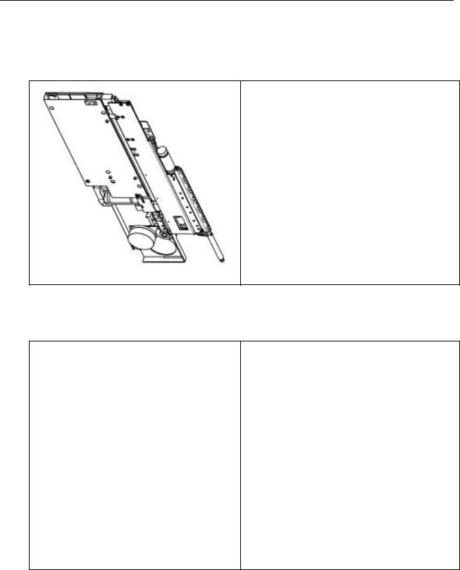
2 Microlab® STAR Instrument
2.1 Overview
Z 
Y
 X
X
The Microlab® STAR is a Sequential Transfer and Aliquoting Robot and performs pipetting operations on liquids in containers on the work surface.
Movable carriers, holding reagent containers, e.g. tubes, microtiter plates, or any other kind of laboratory material are placed on the deck (work surface).
The work surface is divided into 54 tracks (T) of equal width for the purpose of loading carriers. This means the deck has partitions for a maximum of 54 specialized 1-T carriers for sample tubes, or a maximum of 9 6-T carriers for microtiter plates, or a mixture of both. An additional partition is provided for the tip waste station.
The Microlab® STAR is equipped with a pipetting arm containing typically 4, 8, 12 or 16 pipetting channels which work independently. The pipetting arm moves in X- direction, whereas each pipetting channel can move relatively independently both in a Y- and a Z-direction. The Microlab® STAR supports pipetting with disposable tips or with needles.
2-1
Microlab® STAR Service Manual
2.1.1 Key Features
Pipetting Channels
• Monitored air displacement
• (No tubing, no system liquid, no pumps)
• Independent pipetting heads with CORE (Compression-induced O-Ring
Expansion) technology
• Independent Y, Z, volume, and LLD for each pipetting head
CO-RE Technology
• Tips and needles on the same pipetting head
• Flexible use of tips and needles during the same run
• 300 µl channel:
lowand standard-volume tips or needles
when volumes < 5 µl must pipetted.
• 1000 µl channel:
standardand high-volume tips or needles
when volumes > 5 µl must pipetted.
• Soft tip drop-off (minimized aerosol)
2-2
Microlab® STAR Service Manual
Key Features (continued)
Pipetting Heads
• Pressure and capacitive Liquid Level Detection
• Totally accessible deck (each head → each well for an 8-channel ML STAR
Instrument)
• Aspiration monitoring
• 2 types of pipetting heads are available:
• 300 µl (0.5-300 µl) and
• 1000 µl (5-1000 µl)
Tips and Needles
The types of tips and needles currently available are: 10, 300 and 1000 µl disposable tips with or without filter and
50, 300 and 1000 µl washable steel needles For ordering refer to User Manual.
General Precautions:
The pipetting channels are the heart of the Microlab STAR. The instrument will not function properly if these are damaged or are incorrectly adjusted. Therefore you should exercise great care whenever you have to touch the channels - when unpacking or repacking the instrument, dismantling or re-assembling the pipetting arm, replacing channels, etc.
The instrument is provided with a front window. This window is equipped with a sensor that stops any movement immediately and aborts the run when the window is opened.
2-3

Microlab® STAR Service Manual
2.1.2 ML STAR IVD
The Microlab STAR IVD is foreseen to be used in an in vitro diagnostic environment, e.g. for blood analyses and DNA analytics.
Typical applications are:
•Sample preparation for ELISA, LIA, RIA, FIA, agglutination and CLIA tests
•Preparation for amplification techniques for DNA detection
•Sample archiving and pooling.
2.1.2.1Total Aspiration and Dispense Monitoring (TADM)
The Microlab STAR IVD is equipped with an additional safety feature, the pressure based Total Aspiration and Dispense Monitoring (TADM), allowing the in process control of aspiration and dispense steps. The principle works as follows: Before tip pickup, the environmental absolute pressure is measured and used as zero base line. When the liquid level is found, the relative pressure of the air volume within the tip is measured every 10 ms during the following aspiration and dispensing. The measurement values are checked on-line if they are lying within a liquidand volume-specific, predefined tolerance band. If not, the step is stopped with an error message. The TADM enables the detection of leaky or clogged tips, blood clots and foam.
2-4

Microlab® STAR Service Manual
2.1.3 Product variants of Microlab STAR Instruments
Type of Instrument |
Configurations |
Extensions |
|
|
|
Manual load |
4 to 16 channels |
iSwap |
Auto load |
300 µl, or 1000 µl |
Wash station |
|
|
Temperature-controlled |
|
|
carrier |
|
|
Automated vacuum |
|
|
system |
|
|
|
2.1.4 Pipetting Head and Tip / Needle Combinations
All pipetting heads mounted on channels are either of 300 or 1000 µl type. A mixture of these two types is not allowable - the user software will not support a configuration with both types of pipetting heads.
300 µl Pipetting Head |
1000 µl Pipetting Head |
|
|
Low Volume |
Standard Volume |
High Volume |
|
Tip |
Needle |
Tip or Needle |
Tip or Needle |
0.5 – 10 µl 0.5 – 50 µl |
1 - 300 µl |
10 - 1000 µl |
2-5
|
Microlab® STAR Service Manual |
|
2.2 Technical Specifications |
|
|
|
|
|
|
Item |
Value |
|
|
|
|
maximum weight of instrument |
|
|
with the Autoload option and trays installed |
|
|
8 Channel Version: |
145 kg |
|
16 Channel Version: |
155 kg |
|
ML STAR Instrument packed for |
|
|
transportation – total weight including |
|
|
shipping crate: |
< 200 kg |
|
|
|
|
electrical requirements |
|
|
maximum power consumption: |
600W |
|
Voltage: |
115 / 230 V -15 % + 10 % |
|
Frequency: |
50 / 60 Hz ± 5 % |
|
Delayed action fuse: |
|
|
115 V : |
6.3 A |
|
230 V : |
3.15 A |
|
|
|
|
Operating temperature range: |
15-35 °C |
|
|
relative humidity 30 – 85 % with |
|
|
no condensation |
|
|
|
|
Storage temperature range: |
0 - 55 °C |
|
|
relative humidity at a maximum of |
|
|
95 % with no condensation |
|
|
|
2-6
Microlab® STAR Service Manual
Technical Specifications (continued)
Item |
|
Value |
|
|
|
|
|
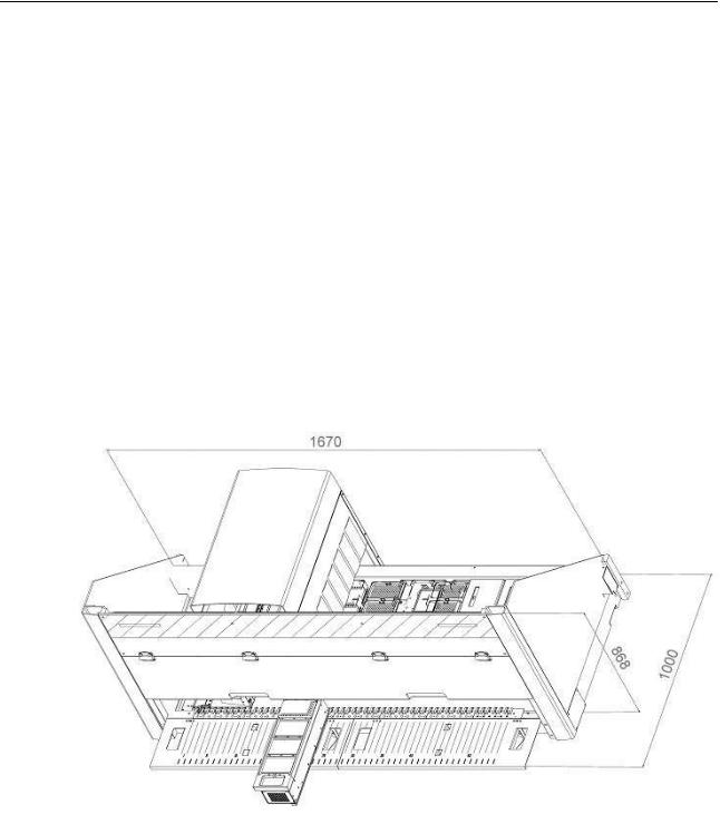
maximum outer dimensions |
|
|
|
Instrument: |
|
Width: 1670 mm |
|
|
|
Height: 868 mm |
|
|
|
Depth: 780 mm |
|
Instrument: incl. attached Autoload tray |
|
Depth: 780 +220 mm = 1000 mm |
|
ML STAR Instrument packed for |
|
Width: 1820 mm |
|
transportation – shipping crate dimensions |
|
Height: 1000 mm |
|
|
|
|
|
|
|
Depth: 900 mm |
|
|
|
|
|
|
|
|
|
2-7

Microlab® STAR Service Manual
Technical Specifications (continued)
Item |
Value |
|
|
Work area |
The Deck has space for 55 Tracks. Track Number 55 |
|
(the rightmost Track) is reserved for Waste Station. |
|
Therefore: |
|
54 Sample carriers, 9 Plate Carriers, or a mixture of |
|
both may be loaded onto the ML STAR Instrument. |
|
A ML STAR Instrument with up to 8 Pipetting Channels |
|
has full sequential access. This means that every |
|
Pipetting Channel reaches any HAMILTON standard |
|
Labware. |
|
A ML STAR Instrument with up to 16 Pipetting |
|
Channels is limited in its Y-direction movements |
|
|
Movement |
Refer to Firmware Reference Guides |
Increments for x, y, z |
|
drives |
|
|
|
2-8

Microlab® STAR Service Manual
Technical Specifications (continued)
|
Criteria |
|
|
Value |
|
|
|
|
|
|
|
|
Barcode Types Specification: |
|
|
|
|
|
The following types of bar code symbol can |
|
|
ISBT standard |
|
|
be recognized by the system: |
|
|
Code 128 (subset B and C) |
|
|
See also user software Menu: |
|
|
|
|
|
|
|
Code 39 |
|
|
|
Tools ML STAR Configuration Editor |
|
|
|
|
|
|
|
Codabar |
|
|
|
Advanced Barcode settings |
|
|
|
|
|
|
|
Code 2 of 5 Interleaved |
|
|
|
|
|
|
|
|
|
|
|
|
UPC A/E |
|
|
|
|
|
JAN/EAN 8 |
|
|
|
|
|
|
|
|
Bar Code Density and Resolution: |
|
|
Up to 32 characters (excluding |
|
|
|
|
|
start, stop and check characters) |
|
|
|
|
|
can be read and decoded. |
|
|
|
|
|
|
|
|
Code density, tolerances: |
|
|
Minimum module width (including |
|
|
The minimum code densities depend on the |
|
|
a print tolerance of 0.0005“) * |
|
|
|
|
0.0065 inches (= 0.1651 mm). |
|
|
|
bar code type and bar code length |
|
|
|
|
|
|
|
|
|
|
|
|
|
|
|
|
|
Print Quality: |
|
|
The bar code print must be of high |
|
|
|
|
|
quality according to USS (Uniform |
|
|
|
|
|
Symbol Specifications) defined by |
|
|
|
|
|
AIM U.S.A. Offset, typographic, |
|
|
|
|
|
intaglio and flexographic printing |
|
|
|
|
|
are suitable. Mechanical dot matrix |
|
|
|
|
|
and thermomatrix printing are not |
|
|
|
|
|
suitable. The label surface may be |
|
|
|
|
|
treated, sealed or plastic-covered. |
|
|
|
|
|
|
|
|
Print Contrast Signal (PCS): |
|
|
Minimum contrast between bars |
|
|
|
|
|
and spaces: PCS 80 % |
|
|
|
|
|
(PCS at 632.8 nm Wavelength) |
|
|
|
|
|
|
|
|
Positioning of Barcode labels: |
|
|
Range on Tubes: 30 – 110 mm |
|
|
measured from Deck |
|
|
Centerline on Plates: 118 mm |
|
|
|
|
|
|
|
2-9

Microlab® STAR Service Manual
Technical Specifications (continued)
General Note on Drive Specifications1:
The User Interface is the Master where all units are 0.1 mm in length and volumes are 0.1 µl.
The master transfers the User's software commands to its slaves and therefore you do not have to know drive resolutions when calculating positions, volumes, etc.
2.2.1 Technical Status of ML STAR Instrument
Technical Status contains all technical data specific to each instrument. It must be updated by the Service Technician whenever any modifications are made.
Technical Status information is stored on the EEPROM of components of ML STAR
Instrument and may viewed, changed and printed via service software only.
It is highly recommended that a copy of the current Technical Data Sheet be held by the Service Technician for his own reference.
1 see in section 12.4.3 Firmware Reference Guides on page 12-19
2-10
 Loading...