


Microlab® STAR User Manual
for User Software 3.0
including Options and Accessories
HAMILTON Bonaduz AG
610766/02 |
Page 1 of 225 |

Microlab® STAR User Manual
Page 2 of 225 |
610766/02 |

Microlab® STAR User Manual
7$%/( 2) &217(176
*HQHUDO ,QIRUPDWLRQ
$ERXW WKLV 0DQXDO
$GGLWLRQDO 0LFURODE 67$5 0DQXDOV
,QWHQGHG 8VH RI WKH 0LFURODE 67$5
2SHUDWLRQ
6DIHW\
1.5.1 |
General Precautions........................................................................................................................... |
8 |
1.5.2 |
Electrical Safety Precautions............................................................................................................. |
9 |
1.5.3 |
Biohazard Precautions....................................................................................................................... |
9 |
1.5.4 |
Computer Precautions ....................................................................................................................... |
9 |
:DUUDQW\ 6WDWHPHQW
&XVWRPHU 6HUYLFH
7KH$UW RI 3LSHWWLQJ
7KH$LU 'LVSODFHPHQW 3LSHWWLQJ 3ULQFLSOH
)URP$VSLUDWLRQ WR 'LVSHQVLQJ
2.2.1 |
Tip Pick-up...................................................................................................................................... |
13 |
2.2.2 |
Aspiration ........................................................................................................................................ |
13 |
2.2.3 |
Dispense .......................................................................................................................................... |
16 |
2.2.4 |
Tip Drop-Off ................................................................................................................................... |
17 |
$YRLGLQJ &RQWDPLQDWLRQ
/LTXLG &ODVVHV 3LSHWWLQJ 0RGHV DQG 0RUH
2.4.1 Liquid Handling Examples.............................................................................................................. |
18 |
3URFHVV &RQWURO
2.5.1 |
Monitored Air Displacement........................................................................................................... |
20 |
2.5.2 |
Capacitance-Based Clot Detection .................................................................................................. |
22 |
'HVFULSWLRQ RI WKH 0LFURODE 67$5
7KH 6WDQGDUG 0LFURODE 67$5
2SWLRQV
3.2.1 4, 8, 12 or 16 Pipetting Channels..................................................................................................... |
24 |
|
3.2.2 |
High and Low Volume Channels .................................................................................................... |
25 |
3.2.3 |
Autoload Option.............................................................................................................................. |
26 |
$FFHVVRULHV
3.3.1 |
Carriers............................................................................................................................................ |
27 |
3.3.2 |
Disposables...................................................................................................................................... |
28 |
3.3.3 |
Needle Wash Station ....................................................................................................................... |
28 |
3.3.4 |
Temperature-Controlled Carrier (TCC)........................................................................................... |
31 |
610766/02 |
Page 3 of 225 |

|
Microlab® STAR User Manual |
|
3.3.5 |
The Automated Vacuum System (AVS) ......................................................................................... |
32 |
3.3.6 |
iSWAP............................................................................................................................................. |
35 |
&RPSXWHU 5HTXLUHPHQWV
3.4.1 |
User Software.................................................................................................................................. |
36 |
3.4.2 |
Firmware ......................................................................................................................................... |
36 |
,QVWDOODWLRQ DQG 6HW 8S
3RZHU 9ROWDJH
3.6.1 |
Basic Microlab STAR ..................................................................................................................... |
37 |
3.6.2 |
Needle Wash Station ....................................................................................................................... |
38 |
0DLQWHQDQFH
9HULILFDWLRQ
'LVSRVDO
7UDLQLQJ
7HFKQLFDO 6SHFLILFDWLRQV
3.11.1 |
Accuracy (Trueness and Precision) Specifications ..................................................................... |
40 |
'HVLJQ RI WKH 8VHU 6RIWZDUH
2YHUYLHZ
0HWKRGV DQG 'HFN /D\RXWV
4.2.1 “Save As”, or Saving Methods and Deck Layouts under Different Names .................................... |
44 |
6WUXFWXUH RI WKH 8VHU 6RIWZDUH
$FFHVV 5LJKWV
)LOH 6WUXFWXUH
,QVWUXPHQW &RQILJXUDWLRQ
'HILQLQJ WKH 'HFN /D\RXW
1HZ 'HFN /D\RXW
6.1.1 |
Save Deck Layout ........................................................................................................................... |
52 |
6.1.2 |
Open Existing Deck Layouts........................................................................................................... |
52 |
$GGLQJ /DEZDUH WR WKH 'HFN /D\RXW
6.2.1 Adding Labware to Track Positions on the Deck............................................................................ |
52 |
|
6.2.2 |
Adding Labware Directly to the Deck............................................................................................. |
55 |
6.2.3 |
Teaching Labware ........................................................................................................................... |
56 |
0DNLQJ &KDQJHV WR WKH 'HFN /D\RXW
6HTXHQFHV
6HTXHQFH (GLWLQJ
7.1.1 Adding Positions to a Sequence ...................................................................................................... |
60 |
|
7.1.2 |
Play.................................................................................................................................................. |
61 |
7.1.3 |
Sorting Racks .................................................................................................................................. |
61 |
7.1.4 Sorting by Grid Columns................................................................................................................. |
61 |
|
Page 4 of 225 |
610766/02 |

|
Microlab® STAR User Manual |
|
7.1.5 Sorting by Grid Rows...................................................................................................................... |
62 |
|
7.1.6 Filter by Probe Head ....................................................................................................................... |
62 |
|
7.1.7 |
Sorting Racks Example ................................................................................................................... |
63 |
7.1.8 |
Sorting Grid Rows Example............................................................................................................ |
65 |
*UDSKLFDO 0HWKRG (GLWRU
*HQHUDO 0HWKRG &RPPDQGV
8VLQJ 0LFURODE 67$5 6SHFLILF 6WHSV
8.2.1 |
SMART Steps ................................................................................................................................. |
70 |
8.2.2 |
Single Steps ..................................................................................................................................... |
84 |
:ULWLQJ D 0HWKRG
(GLWLQJ D 0HWKRG
9DULDEOHV
8VLQJ /LEUDU\ )XQFWLRQV WKH 0/ 67$5 /LEUDU\
%LQGLQJ ,QVWUXPHQW 6WHS 5HWXUQ 9DOXHV
:RUNLQJ ZLWK :RUNOLVWV
8.8.1 |
File Formats..................................................................................................................................... |
93 |
8.8.2 |
Worklist Handling with Microsoft Excel ........................................................................................ |
93 |
:ULWLQJ %DWFK W\SH 0HWKRGV IRU D &KDQQHO 0LFURODE 67$5
+6/ 0HWKRG (GLWRU
5XQ &RQWURO
0HWKRG /LQNLQJ
7KH 0LFURODE 67$5 /LTXLG (GLWRU
&RQFHSW RI /LTXLG &ODVVHV
(GLWLQJ /LTXLG 'HWDLOV
'HILQLQJ D &XVWRP /LTXLG &ODVV
,PSRUWLQJ DQG ([SRUWLQJ /LTXLGV
0LFURODE$96 ±$XWRPDWHG 9DFXXP 6\VWHP
,QWHJUDWLRQ RI WKH$96
&RPPDQGV IRU WKH$96
3DUDOOHO 3URFHVVLQJ ZLWK WKH$96
0HWKRGV IRU 0LFURODE 67$5
2YHUYLHZ
&UHDWH D 0HWKRG WR &RS\ IURP 3ODWH WR 3ODWH 8VLQJ 60$57 6WHSV
&UHDWH D 0HWKRG WR &RS\ IURP 3ODWH WR 3ODWH ZLWK 6LQJOH 6WHSV
&UHDWH D 0HWKRG WR &RS\ IURP 7XEHV WR 3ODWHV 8VLQJ 60$57 6WHSV
$0HWKRG WR 3LSHWWH$OLTXRWV 8VLQJ 60$57 6WHSV
µ&KHUU\ 3LFNLQJ¶ RU +RZ WR &KDQJH D 6HTXHQFH :LWKLQ D 0HWKRG
8VLQJ 60$57 6WHSV
610766/02 |
Page 5 of 225 |

Microlab® STAR User Manual
$0HWKRG 8VLQJ 6WHHO 1HHGOHV 6LQJOH DQG 60$57 6WHSV
,QFOXGLQJ 6DPSOH 5HGXFWLRQ
$*HQHUDO ([DPSOH IRU 8VHU ,Q DQG 2XWSXWV 6DPSOH 7UDFNLQJ
6HTXHQFH 0DQLSXODWLRQ 7LS &RXQWHU DQG 7&& 8VH
8VLQJ WKH L6:$3 URERWLF SODWH KDQGOHU
/RDGLQJ WKH 0LFURODE 67$5
0DQXDO /RDG
5XQQLQJ WKH 0LFURODE 67$5
5XQQLQJ D 6DPSOH 0HWKRG ZLWK WKH ,QVWUXPHQW
5XQ 6LPXODWLRQV
5XQWLPH (UURU +DQGOLQJ
:DON$ZD\ 3UHGHILQHG (UURU +DQGOLQJ
7KH 0LFURODE$7 %DUFRGH )LOH )LOWHU
5HIHUHQFH *XLGH 'HILQLQJ /DEZDUH
7KH /DEZDUH (GLWRU
7\SHV RI ODEZDUH
17.2.1 |
Rectangular Racks and Plates ................................................................................................... |
184 |
17.2.2 |
Containers ................................................................................................................................. |
185 |
17.2.3 |
Circular Racks........................................................................................................................... |
185 |
([DPSOH 'HILQLQJ D 5HFWDQJXODU 5DFN ZLWK &RQWDLQHUV
17.3.1 |
Defining a Container................................................................................................................. |
185 |
17.3.2 |
Defining a Rectangular Custom Rack....................................................................................... |
188 |
17.3.3 |
Defining a Carrier (Template)................................................................................................... |
193 |
6\VWHP )ODJV IRU /DEZDUH 3URSHUWLHV
17.4.1 |
Structure.................................................................................................................................... |
198 |
17.4.2 |
Information for Handling the Autoload Unit ........................................................................... |
198 |
17.4.3 |
Information for Special Units.................................................................................................... |
199 |
= 3RVLWLRQV RI &DUULHUV 5DFNV DQG &RQWDLQHUV
5HIHUHQFH *XLGH ([DPSOHV 8VLQJ WKH +6/ 0HWKRG (GLWRU
&UHDWH D 0HWKRG WR &RS\ IURP 3ODWH WR 3ODWH
$SSHQGLFHV $ *ORVVDU\
% |
,QGH[ |
& |
5HJXODWRU\$IIDLUV |
' |
2UGHULQJ ,QIRUPDWLRQ |
( |
3ULQFLSOHV RI &DOLEUDWLRQ |
) |
1HHGOH :DVK 6WDWLRQ &KHPLFDO &RPSDWLELOLW\ |
Page 6 of 225 |
610766/02 |

Microlab® STAR User Manual
*HQHUDO ,QIRUPDWLRQ
Hamilton’s Microlab STAR is the next generation pipetting workstation. This User Manual is designed to help you get the most out of your Microlab STAR.
You should read through the entire manual before beginning to operate your instrument. This first chapter should be read with particular attention. It contains important information about the use of the Microlab STAR and this manual.
$ERXW WKLV 0DQXDO
This manual is to help users operate the Microlab STAR correctly and safely.
To achieve that aim, Chapter 3 of the manual will describe the different components of the Microlab STAR and how they work. Then, in succeeding chapters, we will describe what can be done with each – the basic operations of aspirating and dispensing liquids. The manual describes both the hardware and software of the Microlab STAR to the extent that a user needs to know them in order to operate the instrument.
After introducing you to the various parts of the Microlab STAR, we show you step by step how to perform typical operations using those components. Sample methods for typical applications guide you through the programming. When you have worked through this manual, you should be quite well able to operate the Microlab STAR.
:DUQLQJV and QRWHV are included in this manual to emphasize important and critical instructions. They are printed in italics in the left margin of the page, begin with the word 'Attention' accompanied by the '!' symbol, or the word ‘Note’, as appropriate.
This manual refers to User Software release 3.0 for the Microlab STAR.
$GGLWLRQDO 0LFURODE 67$5 0DQXDOV
A detailed software reference for the Microlab STAR is to be found in the online help of the User Software. This online help will answer any question you may have about details of the Microlab STAR User Software.
The manner in which the Microlab STAR and its components are to be serviced is described in the 0LFURODE 67$5 6HUYLFH 0DQXDO. This manual will be made available to Hamilton-
authorized service technicians.
Whenever a manual amendment is issued, detailed instructions on amending the existing manual will be provided.
,QWHQGHG 8VH RI WKH 0LFURODE 67$5
The Microlab STAR is a robotic pipetting workstation, in other words, a sampler used for pipetting liquid samples in an automated process suitable for medium to high throughput with a high degree of flexibility in pharmaceutical, veterinary and genetics applications.
A user will typically wish to carry out low, medium, or high volume contamination-free pipetting with disposable tips or with steel needles.
At the present time, the Microlab STAR is classified as a general laboratory instrument and is not specifically validated as an LQ YLWUR diagnostic device.
610766/02 |
Page 7 of 225 |

Microlab® STAR User Manual
2SHUDWLRQ
The operator of the Microlab STAR must have attended an appropriate training course. The procedures contained within this manual have been tested by the manufacturer and are deemed to be fully functional. Any departure from the procedures given here could lead to erroneous results or malfunction.
6DIHW\
The following section describes the main safety considerations, electrical and biological, in operating this product, and the main hazards involved.
*HQHUDO 3UHFDXWLRQV
When using Microlab STAR, Good Laboratory Practices (GLP) should be observed. Suitable protective clothing, safety glasses and protective gloves should be worn.
During Microlab STAR operation, do not place hands in the way of moving parts or on the working deck. Keep your head and hands away from the work surface of the Microlab STAR when it is in operation – the pipetting arm and channels move fast and it is possible to sustain an injury. In general, never lean over the Microlab STAR when working with it.
When working with samples, do not switch tubes around after they have been identified by the barcode reader. This could result in incorrect test data.
When working with samples which will be used in particularly sensitive tests, take into account evaporation and condensation that may occur while the method is running.
Perform test runs i) with deionized water and ii) with the final liquids, prior to routine use. Test for all the liquid classes you are going to use.
Liquid level detection needs to be explicitly tested when working with foaming liquids.
If sampling aggressive liquids, use filter tips.
During operation, the Microlab STAR should be shielded from direct sunlight and intense artificial light.
127(
'LVFDUG XVHG WLSV 'R QRW UHXVH WKHP 8VH ILOWHU WLSV IRU WDVNV ZKLFK DUH VHQVLWLYH WR FURVV FRQWDPLQDWLRQ DHURVROV 1RWH WKDW IRDP PD\ DIIHFW WKH DFFXUDF\ RI OLTXLG OHYHO GHWHFWLRQ
$V D JHQHUDO VDIHW\ SULQFLSOH WKH LQQHU GLDPHWHU RI VDPSOH WXEHV UHDJHQW YHVVHOV HWF PXVW EH JUHDWHU WKDQ WKH FKDQQHO GLDPHWHU RI PP
,I WKH V\VWHP LV SDXVHG GR QRW ZDLW WRR ORQJ EHIRUH UHVXPLQJ WKH UXQ /RVV RI OLTXLG IURP D IXOO WLS PD\ UHVXOW LQ LQYDOLG GDWD
'R QRW RYHUILOO UHDJHQW FRQWDLQHUV WXEHV RU RWKHU OLTXLG FRQWDLQHUV 6ZLWFK RII WKH SRZHU RI WKH 0LFURODE 67$5 GXULQJ PDLQWHQDQFH
6HW XS WKH 0LFURODE 67$5 ZLWK LWV EDFN WR D ZDOO WR SUHFOXGH DQ\ UHDU DFFHVV WR WKH ZRUN DUHD
7KH EUHDNGRZQ RI WKH SRZHU VXSSO\ GXULQJ D UXQ PD\ FDXVH WKH ORVV RI GDWD ,I WKH ORVV RI GDWD LV XQDFFHSWDEOH XVH DQ LQGHSHQGHQW SRZHU VXSSO\
Page 8 of 225 |
610766/02 |

Microlab® STAR User Manual
2SHQLQJ WKH IURQW ZLQGRZ GXULQJ D UXQ ZLOO OHDG WR D V\VWHP DERUW DQG PD\ FDXVH WKH ORVV RI GDWD
7R DYRLG FRPSXWHU EUHDNGRZQV HQVXUH WKDW WKHUH LV DOZD\V HQRXJK VWRUDJH FDSDFLW\ RQ \RXU KDUG GULYH
1HYHU GLVDEOH DQ\ VHFXULW\ PHDVXUH
'R QRW OHDYH WLSV RU QHHGOHV SLFNHG XS RQ WKH SLSHWWLQJ FKDQQHOV IRU ORQJ SHULRGV VXFK DV RYHUQLJKW 7KLV PD\ FDXVH GDPDJH WR WKH 2 ULQJV
For repair or shipment, all mechanical parts must be put in their rest positions. A Microlab STAR sent away for repair must also be decontaminated if it was in a laboratory environment with infected or hazardous materials. The Microlab STAR must be repacked in the original shipping crate and only by an authorized service technician. There should be no containers or tips on the Microlab STAR during transportation.
Only original HAMILTON Microlab STAR-specific parts and tools may be used with the Microlab STAR, e.g. carriers, racks, tips, steel needles, and waste containers. Commercially available liquid containers, such as microtiter plates and tubes, may of course be used.
If working with contaminated samples, the user need not touch them. The Microlab STAR will drop its used tips into a waste container that should be emptied as soon as it is full.
The Microlab STAR products conform to European norms as regards interference immunity. However, if the Microlab STAR is subjected to electromagnetic RF fields, or if static electricity is discharged directly onto the Microlab STAR, its Liquid Level Detection ability (see below) may be negatively affected. It is therefore recommended that the Microlab STAR be kept away from other equipment that emits electromagnetic RF fields in the laboratory, and that static electricity be minimized in its immediate environment.
(OHFWULFDO 6DIHW\ 3UHFDXWLRQV
Before removing a mechanical or electrical component, the Microlab STAR must first be switched off and disconnected from the main electricity supply and PC.
%LRKD]DUG 3UHFDXWLRQV
If the Microlab STAR becomes contaminated with biohazardous material, it should be cleaned in accordance with the maintenance procedures given in the section “Maintenance” (3.7). Observe and carry out the maintenance procedures given. Failure to do so may impair the reliability and correct functioning of the Microlab STAR.
If working with biohazardous samples, observe and carry out the maintenance procedures paying particular regard to cleaning and decontamination. Wear gloves when handling the pipetting arm and channels, the carriers, racks, and containers, and the tips and steel needles. Avoid touching the discarded tips in the waste container. Any surfaces on which liquid is spilled must be decontaminated.
&RPSXWHU 3UHFDXWLRQV
Guard against software viruses. Use only manufacturer’s original installation CD-ROM sets for the operating system, and the original HAMILTON software.
Only the HAMILTON User Software and the firmware protocol (CoCo/KuSt, cf 0LFURODE 67$5 6HUYLFH 0DQXDO) may be used to control the Microlab STAR.
610766/02 |
Page 9 of 225 |

Microlab® STAR User Manual
:DUUDQW\ 6WDWHPHQW
HAMILTON Bonaduz AG, CH-7402 Bonaduz / Switzerland is the manufacturer of the Microlab STAR.
The Microlab STAR is sold in accordance with the general conditions of sale of HAMILTON Bonaduz AG.
HAMILTON warrants this product to be free of defects in material and workmanship for a period of 12 months from the date of delivery, ex works Bonaduz.
HAMILTON or the authorised HAMILTON representative will repair or replace, at its option and free of charge, any product that under proper and normal use proves to be defective during the warranty period.
HAMILTON shall in no event be liable or responsible for any incidental or consequential damage, either direct or contingent.
HAMILTON accessories and consumable products, e.g. carriers, racks, tips, steel needles, and waste containers, are warranted to be free of defects in material and workmanship at the time of delivery only.
The above warranty shall not apply if:
•the product has not been operated in accordance with the user manual;
•the product is not regularly and correctly maintained;
•the product is not maintained, repaired or modified by a HAMILTON-authorized representative or user;
•parts other than original HAMILTON parts are used, except for liquid containers such as microtiter plates and tubes;
•the product or parts thereof have been altered without written authorization from HAMILTON Bonaduz AG;
•the product is not returned properly packed in the original HAMILTON packaging.
HAMILTON reserves the right to refuse to accept any product that has been used with radioactive or microbiological substances, or any other material that may be deemed hazardous to employees of HAMILTON. Such a product has to be properly decontaminated and marked.
HAMILTON endeavours to provide prompt and satisfactory service.
Page 10 of 225 |
610766/02 |
Microlab® STAR User Manual
&XVWRPHU 6HUYLFH
Customer service will be provided in the first instance by the network of HAMILTON representatives. In the event of any problem experienced with your Microlab STAR, the first recourse is your local HAMILTON representative. For further problems requiring hardware or software expertise, the Technical Support department at HAMILTON Bonaduz AG will be available by phone, fax or e-mail to deal with your queries. Here is their address, phone, fax and e-mail:
(XURSH $IULFD DQG $VLD |
|
|
|
HAMILTON Bonaduz AG |
Phone |
+41 81 641 6060 |
|
Technical Support |
Fax |
+41 81 641 6070 |
|
|
|||
P.O. Box 26 |
|
|
|
CH-7402 Bonaduz / Switzerland |
E-mail: itechsupport@ hamilton.ch |
||
|
|||
$PHULFDV )DU (DVW DQG 3DFLILF 5LP |
|
|
|
HAMILTON Company |
Toll Free: |
(800) 648-5950 |
|
P.O. Box 10030 |
Phone |
(775) 858-3000 |
|
Reno, NV 89520-0012 |
Fax |
(775) 856-7259 |
|
E-mail: tech@hamiltoncompany.com |
|||
|
|||
USA
610766/02 |
Page 11 of 225 |
Microlab® STAR User Manual
7KH $UW RI 3LSHWWLQJ
In this chapter the process of pipetting with the Microlab STAR is described. Pipetting means transfer of small quantities of liquid from one container to another. A pipetting operation is achieved by aspirating (drawing) liquid from a source container, then transferring and dispensing (dropping) it into a target container.
7KH $LU 'LVSODFHPHQW 3LSHWWLQJ 3ULQFLSOH
The Microlab STAR is based on the DLU GLVSODFHPHQW SLSHWWLQJ principle, comparable to the functioning of hand pipettes. Air displacement means that the liquid is aspirated into and dispensed from a disposable tip or needle by the movement of a plunger. Between the plunger and the liquid surface is air. No system liquid of any kind is involved in the Microlab STAR.
7KH $LU 'LVSODFHPHQW 3LSHWWLQJ 3ULQFLSOH
The air displacement principle has the following advantages:
•Independent and modular design of pipetting heads for most flexible assay programming.
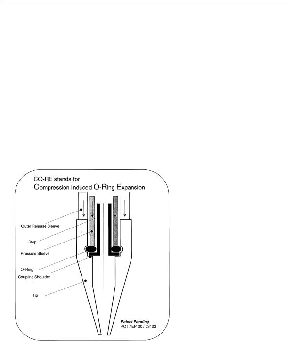
•CO-RE (compression-induced O-ring expansion) technology for the flexible coupling of tips or needles to the pipetting channel.
•Tips or reusable needles of three sizes on the same head in the same run.
Page 12 of 225 |
610766/02 |

Microlab® STAR User Manual
•The construction principle enables pressure-based liquid level detection and aspiration monitoring.
•No contamination or dilution by system liquids.
•No drops due to moving tubes.
•No problems with corroded tubing, pumps, etc.
•Same commonly accepted pipetting principle as for hand pipettes.
)URP $VSLUDWLRQ WR 'LVSHQVLQJ
In this section we describe in detail the processes involved in a simple pipetting step.
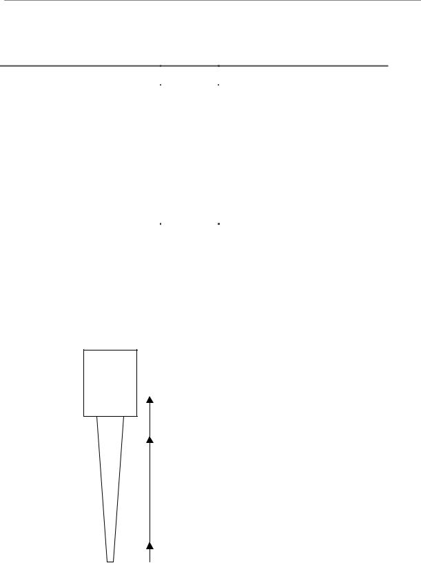
7LS 3LFN XS
The first task for the Microlab STAR is to pick up a disposable tip or a reusable steel needle. For tips, special carriers typically holding 5 tip racks of 96 tips are placed on the instrument deck. Steel needles may be picked up directly from the wash station, or from a separate needle rack, which typically is a tip rack on a tip rack carrier with needles instead of tips.
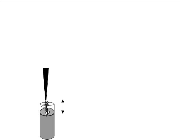
$VSLUDWLRQ
The first step within an aspiration and dispense cycle is to aspirate a variable amount of blowout air, which is used at the end of the (last) dispense, to blow the liquid out of the tip. This is done with the tips still in the air.
To start the aspiration of liquid, the tip must make contact with the liquid. This may be done by moving the tip to a IL[HG KHLJKW. This height must be chosen to be permanently below the
liquid level, to prevent the aspiration of air. On aspiration, the tip follows the falling liquid level (if so specified) according to the volume aspirated. The distance to follow is computed from the known geometry of the (first segment of the) liquid container.
More elegantly, and with greater safety, the liquid level of the vessel to be aspirated from can be detected. This can be provided by STAR’s /LTXLG /HYHO 'HWHFWLRQ (LLD) feature, based
on either capacitive (cLLD) or pressure (pLLD) signal detection. For conductive liquids, capacitive LLD should normally be used. The sensitivity of the capacitive LLD that is to be used depends on the vessel size and the conductivity (or polarity) of the liquid that is to be detected. For a solution of 0.1% NaCl in distilled water, the sensitivities are:
F//' 6HWWLQJ 6HQVLWLYLW\ /HYHO
1Very High
2High
3Medium
4Low
9HVVHO
384-well plates
96-well round-bottom plates
96-well flat-bottom plates
Tubes
610766/02 |
Page 13 of 225 |

Microlab® STAR User Manual
127(
8VLQJ DQ LRQLF EXIIHU LQ \RXU DVVD\ LQ SODFH RI GLVWLOOHG ZDWHU PD\ KHOS WR RYHUFRPH OLTXLG OHYHO GHWHFWLRQ SUREOHPV
8VH RQO\ RULJLQDO +DPLOWRQ ODEZDUH FDUULHUV )RU D SURSHU FDSDFLWLYH OLTXLG OHYHO GHWHFWLRQ D VXIILFLHQW FRQGXFWLYH FRXSOLQJ RI FDUULHU DQG ODEZDUH WXEHV RU PLFURSODWHV LV FUXFLDO
For non-conductive liquids, or in case of an insufficient electrical coupling between container bottom and carrier, pressure LLD should be used. Pressure LLD only works with new and empty tips for the aspiration of liquids. The suitable settings depend on the tip size and on the type of liquid.
300 l channel:
|
|
S//' 6HWWLQJ |
6HQVLWLYLW\ /HYHO |
7LS |
/LTXLG |
|
|
1 |
Very High |
Standard |
Low boiling point, low viscosity |
|
|
2 |
High |
Low |
Low boiling point, low viscosity |
|
|
3 |
Medium |
Standard |
Water or higher viscosity |
|
|
4 |
Low |
Low |
Water or higher viscosity |
1000 l channel: |
|
|
|
||
|
|
|
|
|
|
|
|
S//' 6HWWLQJ |
6HQVLWLYLW\ /HYHO |
7LS |
/LTXLG |
|
|
1 |
Very High |
Standard |
Low boiling point, low viscosity |
|
|
2 |
High |
High |
Low boiling point, low viscosity |
|
|
3 |
Medium |
Standard |
Water or higher viscosity |
|
|
4 |
Low |
High |
Water or higher viscosity |
In the case of DVSLUDWLRQ IURP IRDPLQJ OLTXLGV, capacitive liquid level detection in particular may not detect the surface properly. As an alternative, try pressure LLD, or a combination of both. If you are using a combination of both LLD types, the maximum height difference between the two independent LLDs can be used as a parameter.
Page 14 of 225 |
610766/02 |
Microlab® STAR User Manual
The following table gives dead volumes for both pressureand capacitance-based liquid level detection in various containers.
Labware |
|
Vmin/ l |
|
Carrier |
Tubes, 16 mm x 100 mm |
200 |
|
SMP-CAR-24 |
|
Tubes, 12 mm x 75 mm |
150 |
|
SMP-CAR-32 |
|
Eppendorf tubes 1.5 ml |
50 |
|
SMP-CAR-EPIL |
|
Eppendorf tubes 0.5 ml |
50 |
|
SMP-CAR-EPIS |
|
96-well PCR plate (200 l/well) |
50 |
|
PLT-CAR-L5PCR |
|
96-well flat-bottom microplate |
75 |
|
PLT-CAR-L5MD |
|
384-well flat-bottom microplate |
50 |
|
PLT-CAR-L5MD |
|
96-deepwell microplate (archive) |
|
150 |
|
PLT-CAR-L5AC |
Once the liquid surface is detected, an additional immersion depth (typically 2mm) is reached to prevent the aspiration of air, and DVSLUDWLRQ starts. The tip follows the falling liquid level (if
so specified) according to the volume aspirated. Then, the tip leaves the liquid slowly and heads for the vessel to dispense into.
Finally, to prevent droplet formation, a variable amount of transport air is aspirated. After an aspiration step, the situation within the tip looks like this.
Channel
Blowout air (optional, may reach into channel)
T
i
p Liquid
Transport air (optional)
7KH VLWXDWLRQ ZLWKLQ WKH WLS DQG WKH FKDQQHO DIWHU DVSLUDWLRQ
610766/02 |
Page 15 of 225 |
Microlab® STAR User Manual
'LVSHQVH
The transport air that was aspirated at the end of the aspiration step is first dispensed with the tip still in the air. Dispensing of the liquid may now occur in two different modes: to the liquid surface or in a jet.
|
|
Dispense in Jet |
|
|
Dispense to Surface |
|
|
|
|
|
|
|
|
|
|
|
|
|
|
|
|
|
|
|
|
|
|
|
|
|
|
|
|
|
|
|
|
|
|
|
|
To ensure that the specified accuracy is achieved, volumes below 20 l should always be GLVSHQVHG WR D OLTXLG VXUIDFH. For dispensing to a liquid surface use cLLD to detect the
position of the surface and then dispense by following the rising liquid level. For volumes larger than 20 l the liquid can be GLVSHQVHG LQ D MHW without touching the surface. To
dispense in a jet specify a position a couple of millimeters above the surface and dispense by following the rising liquid level. For dispensing in a jet, a varying amount of blowout air is used to make sure that all liquid is dispensed from the tip.
However, dispensing to the surface of an empty vessel (touch off) is also possible For dispensing into an empty container, position the tip less than 1 mm (typically 0.4 mm) above the bottom of the container and dispense, following the rising liquid level.
After the dispense, the situation within the tip looks like this:
Channel
Blowout air (optional)
T
i
p Liquid
Stop back volume (optional)
Transport air as specified Transport air as specified on dispense (optional) on aspiration(optional)
6LWXDWLRQ RQ GLVSHQVH )LUVWO\ WUDQVSRUW OLTXLG DQG EORZRXW YROXPH DUH GLVSHQVHG IROORZHG E\ DQ DVSLUDWLRQ RI VWRS EDFN YROXPH LQ WKH FDVH RI SDUWLDO YROXPH GLVSHQVHV DQG WUDQVSRUW DLU
Page 16 of 225 |
610766/02 |

Microlab® STAR User Manual
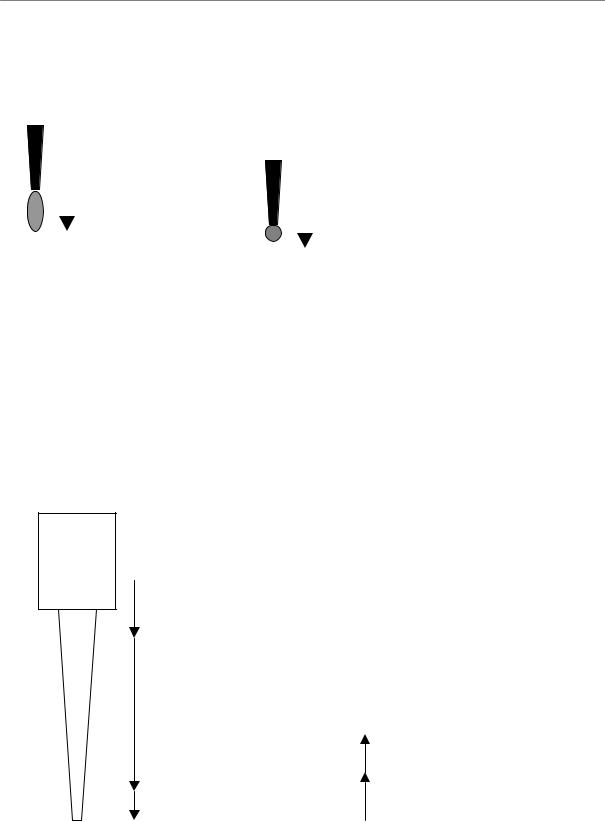
7LS 'URS 2II
The final step is to eject the used tip into the waste container of the Microlab STAR. A needle will be placed back into the wash station, where the wash process may be started directly.
$YRLGLQJ &RQWDPLQDWLRQ
If cross-contamination is a concern, consider the following approaches:
•Use only HAMILTON tips on the Microlab STAR.
•Use new tips for every pipetting step to avoid carry-over between different wells or containers.
•Use filter tips to avoid contamination of the pipetting channel by jets, aerosols, etc.
•Always dispense to a surface. Dispensing in a jet may produce aerosols and thus cause cross-contamination.
•Always dispense using a residual volume, i.e., do not completely empty the tip on dispense. This can be achieved e.g. by aspirating 10 l and dispensing only 9 l.
/LTXLG &ODVVHV 3LSHWWLQJ 0RGHV DQG 0RUH
In general, pipetting on the principle of air displacement (as with hand pipettes) is sensitive to
•the manner of pipetting (e.g. surface or jet),
•tip or needle type
•environmental effects (temperature, pressure, humidity), and
•liquid type.
The instrument’s behavior is determined by specifying the pipetting mode (e.g., surface or jet mode) and the liquid class. Pipetting mode and liquid class represent two independent sets of information which both have to be specified. For aspiration, three modes are possible:
•Simple “Aspiration”, for all standard cases,
•“Consecutive Aspiration” for aspiration with a tip that has already aspirated liquid, and
•“Aspirate All” for aspiration of all the liquid within a cup (specify a volume larger than what is expected within the cup). In this case, aspiration monitoring is deactivated and the tip will follow the falling liquid level (if specified) to the bottom of the container, staying there for the rest of the aspiration.
For dispensing, four modes are possible:
•“Surface Dispense Part Volume” for dispensing only a part of the liquid in the tip to a surface, leaving a residual volume in the tip,
•“Surface Dispense Empty Tip” for dispensing all the liquid in the tip to a surface,
•“Jet Dispense Part Volume” for dispensing only a part of the liquid in the tip in a jet, i.e. without touching a surface, leaving a residual volume in the tip,
•“Jet Dispense Empty Tip” for dispensing all the liquid in the tip in a jet.
610766/02 |
Page 17 of 225 |

Microlab® STAR User Manual
The OLTXLG FODVV stores all relevant background parameters, such as flow rates and volume corrections, for one pipetting cycle, i.e. for one aspiration and the subsequent dispense(s). Depending on the pipetting mode chosen, only a subset of the parameters of the liquid class is active. According to the different dependencies listed above, liquid classes have attributes related to their intended use: tip type, liquid name, and dispense mode.
Different liquid classes are provided with the User Software and optimized for different liquids, tip types, and important pipetting processes, such as aspiration followed by dispensing either to a surface or in a jet. HAMILTON has optimized the standard liquid classes with great care to assure the best pipetting accuracy. To change HAMILTON standard liquid classes, store the class under a different name first. For special applications, the user can define his or her own liquid class to achieve the highest accuracy with the compounds and volumes of interest. For this purpose a Liquid Editor comes with the Microlab STAR User Software. It is described in Chapter 11 below.
127(
$OZD\V XVH WKH VDPH OLTXLG FODVV IRU RQH DVSLUDWLRQ DQG GLVSHQVH F\FOH 2WKHUZLVH XQFRQWUROOHG UHVLGXDO YROXPHV PD\ EH OHIW ZLWKLQ WKH WLS RU RWKHU HUURUV UHODWLQJ WR WKH VXP RI YROXPHV PD\ RFFXU
/LTXLG +DQGOLQJ ([DPSOHV
Here are some examples of frequently-used combinations of liquid classes and pipetting modes:
$VSLUDWH ≥ O RI D ZDWHU OLNH OLTXLG GLVSHQVH O LQWR DQ HPSW\ ZHOO SODWH XVH VWDQGDUG WLSV FKDQJH WLSV HYHU\ F\FOH:
Liquid Class: |
StandardVolume_Water_DispenseJet |
Aspiration Mode: |
Aspiration |
Dispense Mode: |
Jet Dispense Empty Tip |
Detection: |
Aspiration: LLD = pressure or capacitance or both, submerge to a |
|
depth of 2mm, following liquid level |
|
Dispense: Fixed height of 5mm, not following liquid level |
$VSLUDWH D ZDWHU OLNH OLTXLG VLQJOH GLVSHQVH LQWR D SUH ILOOHG ZHOO SODWH XVH ORZ YROXPH WLSV FKDQJH WLSV HYHU\ F\FOH:
Liquid Class: |
LowVolume_Water_DispenseSurface |
Aspiration Mode: |
Aspiration |
Dispense Mode: |
Surface Dispense Empty Tip (in the liquid class selected here, the |
|
blowout volume is 0) |
Detection: |
Aspiration: LLD = Pressure or Capacitance or both, Submerge Depth |
|
2mm, following liquid level |
|
Dispense: Capacitance LLD on, following liquid level |
Page 18 of 225 |
610766/02 |

Microlab® STAR User Manual
$VSLUDWH ≥ O RI D ZDWHU OLNH OLTXLG GLVSHQVH WKH VDPH DPRXQW LQWR DQ HPSW\
ZHOO SODWH NHHS WLSV
Liquid Class: |
StandardVolume_Water_DispenseJet |
Aspiration Mode: |
Aspiration |
Dispense Mode: |
Jet Dispense Empty Tip (empty tip only) |
Detection: |
Aspiration: Capacitance LLD, submerge depth 2mm, following liquid |
|
level |
|
Dispense: Fixed height of 5mm, not following liquid level |
Comment: |
On first aspiration, pre-wetting of the tip by 1-3 mixing cycles is |
|
necessary to equalize conditions for initial and subsequent dispenses. |
$OLTXRWLQJ of liquid means aspirating a given volume all at once and dispensing several partial volumes (aliquots) in a jet to different containers. In this frequently-used pipetting procedure, measurements have revealed that the accuracy of the first and the last aliquot are
often not within the specified range. Therefore, to dispense e.g. 10 aliquots of 20 l of a ZDWHU OLNH OLTXLG with the ML-STAR, aspirate 240 l and dispense 20 l directly back into the
container. This is followed by dispensing 10 of the 20 l aliquots. The last aliquot of 20 l is discarded into another container or ejected with the tip. In addition, after the dispense of every aliquot, a given amount of air is aspirated and dispensed with the next aliquot.
Liquid Class: |
StandardVolumeWaterAliquotJet |
Aspiration Mode: |
Aspiration |
Dispense Mode: |
Jet Dispense part volume |
Detection: |
Aspiration: Capacitance LLD, Submerge Depth 2mm, following liquid |
|
level |
|
Dispense: Fixed height of 5mm, not following liquid level |
610766/02 |
Page 19 of 225 |

Microlab® STAR User Manual
The following table gives sample values and results for preand post-aliquot volumes (please note that these are not technical specifications):
&KDQ |
7LS |
/LTXLG |
3UH |
9 >—O@ |
1R RI |
9 >—O@ |
9 >—O@ |
&9 |
5 |
&ODVV |
QHO |
7\SH |
|
ZHW |
PDLQ |
$OLT |
SUH |
SRVW |
|
|
|
7\SH |
|
|
|
DOLT |
|
DOLT |
DOLT |
|
|
|
300 |
Std |
Water |
Yes |
20 |
12 |
20 |
20 |
1.5 |
-2.6 |
A |
300 |
Std |
Water |
Yes |
50 |
4 |
50 |
20 |
2.0 |
-1.1 |
A |
300 |
Std |
Serum |
Yes |
20 |
12 |
40 |
40 |
2.0 |
|
B |
300 |
Std |
Serum |
Yes |
50 |
4 |
70 |
50 |
4.5 |
|
B |
1000 |
Std |
Water |
Yes |
10 |
12 |
20 |
>10 |
3.9 |
-3.8 |
A |
1000 |
Std |
Water |
Yes |
20 |
12 |
20 |
20 |
2.5 |
-3.2 |
A |
1000 |
Std |
Water |
Yes |
50 |
4 |
50 |
20 |
2.0 |
-1.5 |
A |
1000 |
High |
Water |
No |
20 |
12 |
20 |
20 |
5 |
-1.6 |
C |
1000 |
High |
Water |
No |
50 |
12 |
50 |
50 |
2.5 |
-1.2 |
C |
1000 |
High |
Water |
No |
100 |
8 |
50 |
100 |
1.5 |
-0.9 |
C |
1000 |
High |
Water |
No |
200 |
4 |
50 |
100 |
1.5 |
-1.5 |
C |
1000 |
High |
Serum |
Yes |
100 |
8 |
100 |
100 |
1.0 |
-1.1 |
D |
7DEOH RI $OLTXRWV 7LS W\SHV DUH 6WG 6WDQGDUG 9ROXPH 7LS —O +LJK +LJK 9ROXPH 7LS
—O 3UH ZHW ,I ³<HV´ SUH ZHWWLQJ E\ IROG PL[LQJ RQ DVSLUDWLRQ ZLWK DVSLUDWLRQ YROXPH QHFHVVDU\ 9 PDLQ DOLT 9ROXPH RI PDLQ DOLTXRW 9 SUH DOLT 9ROXPH RI SUH DOLTXRW 9 SRVW DOLT 9ROXPH RI SRVW DOLTXRW &9 3UHFLVLRQ FRHIILFLHQW RI YDULDWLRQ IRU GHILQLWLRQ VHH VSHFV 5 7UXHQHVV IRU GHILQLWLRQ VHH VSHFV 7KH 5 DQG &9 YDOXHV PHQWLRQHG KHUH DUH W\SLFDO UHVXOWV IRU PHDVXUHPHQWV &ODVV /LTXLG FODVV WR EH XVHG $ ´6WDQGDUG9ROXPHB:DWHUB$OLTXRW-HW³ % ³6WDQGDUG9ROXPHB6HUXPB$OLTXRW-HW³ & ³+LJK9ROXPHB:DWHUB$OLTXRW-HW³ ' ³+LJK9ROXPHB6HUXPB$OLTXRW-HW³ 7KH GLVSHQVH PRGH IRU DOO FDVHV LV ³-HW 'LVSHQVH (PSW\ 7LS³
3URFHVV &RQWURO
0RQLWRUHG $LU 'LVSODFHPHQW
The Microlab STAR is equipped with an aspiration monitoring feature. During the aspiration process, the pressure within the pipetting channel is measured in real time. Analyzing the shape of the p(t) curve, the system can distinguish the following situations:
-A correct aspiration takes place.
-Air is aspirated into the tip (because, for example, the cup has not been filled properly).
-A clot blocks the tip.
The aspiration monitoring can be switched on and off for each individual aspiration step of a method using the appropriate commands (see section 2.4). For pressure-based clot detection, a threshold can be given in arbritrary A/D (analog/digital) values (typically 100 A/D
Page 20 of 225 |
610766/02 |
Microlab® STAR User Manual
values). The range of A/D values of the pressure sensor is from around 800 (at ambient pressure) to <10 A/D values for 18 mbar below ambient pressure. For comparison, the hydrostatic pressure of 100 l of water in our standard tip is around 2 mbar.
p(t)
ASP OK√
 Cup Empty on ASP
 Tip blocked on
ASP (Clot)
time/ms
$VSLUDWLRQ PRQLWRULQJ EDVHG RQ SUHVVXUH
127(
3UHVVXUH EDVHG PRQLWRULQJ ZRUNV RQO\ ZLWK XQXVHG GLVSRVDEOH WLSV QRW ZLWK QHHGOHV
7KH YROXPH UDQJH IRU WKH PRQLWRULQJ GHSHQGV RQ WKH VSHFLILF DVVD\ 7KH ORZHU OLPLW LV LQ PDQ\ FDVHV DQ DVSLUDWLRQ YROXPH RI O
3UHVVXUH EDVHG PRQLWRULQJ KDV EHHQ RSWLPL]HG IRU DTXHRXV VROXWLRQV RQO\
610766/02 |
Page 21 of 225 |
Microlab® STAR User Manual
&DSDFLWDQFH %DVHG &ORW 'HWHFWLRQ
In addition to pressure-based clot detection, the ML STAR is equipped with capacitancebased clot detection, too. This detection approach works for an aspiration with capacitance liquid level detection switched on. The system measures the conductive signal when the tip leaves the liquid after aspiration. Due to the air gap between tip and liquid, the capacitance signal will vanish once a given height is reached (the “clot retract height”, which is specified within the liquid class). If a clot is present, it bridges the distance and the signal will remain, resulting in an error message. A typical clot retract height is 2-5 mm. This is illustrated below.
Clot Retract Height
This clot detection is independent of pressure-based monitoring.
Page 22 of 225 |
610766/02 |

Microlab® STAR User Manual
'HVFULSWLRQ RI WKH 0LFURODE 67$5
7KH 6WDQGDUG 0LFURODE 67$5
STAR stands for Sequential Transfer and Aliquoting Robot. The Microlab STAR performs pipetting operations on liquids in containers placed on its work surface.
The basic model Microlab STAR contains a work surface, called a deck, for placing movable carriers. These carriers hold reagent containers, such as tubes, microtiter plates, or other kinds of labware.
Pipetting
Arm
z 
y
(0,0,0) x
Pipetting Autoload Channel/ Unit
Pipetting Head
Front Shield
and Window
Deck
|
Loading |
|
Tray |
Carrier for tubes, |
Waste |
microtiter plates, |
Container |
etc. |
|
7KH 0LFURODE 67$5
The Microlab STAR’s deck is divided into 54 equal tracks (T) for loading carriers with predetermined positions. This obviates the need for precise measurement of positions. The deck has partitions for a maximum of 54 specialised 1-T carriers for sample tubes, or a maximum of 9 6-T carriers for microtiter plates and CO-RE tips. An additional partition space is provided for the tip waste container.
610766/02 |
Page 23 of 225 |

Microlab® STAR User Manual
The instrument’s internal coordinate system is shown in the figure, located at its origin.
The Microlab STAR is equipped with a pipetting arm typically containing 8 pipetting channels which work independently. The pipetting arm can move in an X direction, whereas each pipetting channel can move relatively independently both in a Y and a Z direction. The Microlab STAR supports pipetting with disposable tips or with needles.
The pipetting channels have a set “travelling height” of 245 mm above the origin, or 145 mm between the tip of the disposable tip and the deck of the instrument. That means that when a channel is to move from one location on the deck to another, it automatically does so at that particular height. This is a safety precaution, so that channels will not collide with any items that may be on the deck.
The instrument is equipped with a front shield and a hinged transparent window made of plexiglass. This window is equipped with a magnetic switch and it is locked during a run.
$77(17,21
$Q DERUWHG UXQ VWRSSHG E\ RSHQLQJ WKH IURQW ZLQGRZ FDQQRW EH UHVWDUWHG ,I \RX QHHG WR RSHQ WKH ZLQGRZ GXULQJ D UXQ FOLFN ³3DXVH´ LQ WKH 5XQ 6FUHHQ ZDLW XQWLO WKH LQVWUXPHQW VWRSV DQG WKHQ RSHQ WKH ZLQGRZ
2SWLRQV
Options are defined as components or configurations that are part of the instrument initially provided to the customer as specified by that customer. Options cannot be added later, whereas accessories can (see Section 3.3 “Accessories” below). The instrument’s configuration is set within the configuration editor of the User Software.
RU 3LSHWWLQJ &KDQQHOV
The Microlab STAR comes with 4, 8, 12, or 16 pipetting channels working in parallel for simultaneous transfer of liquids.
Instruments with 4,8, or 16 channels are best operated with carriers, holding microplates and tip racks in landscape orientation (e.g. PLT-CAR-L5MD), whereas carriers with portrait orientation for microplates and tips (e.g. PLT-CAR-P3MD) are best suited for the 12-channel Microlab STAR. In addition, increasing the number of channels to 12 or 16 reduces the “random access space” of the Microlab STAR, i.e., the space that can be reached with all pipetting channels. This is shown in the following table:
1R RI |
< PP |
< PP |
&KDQQHOV |
Rel. to Instr. Coordinate System |
|
RU |
77.5 |
77.5 + 465 |
|
113.5 |
113.5 + 393 |
|
149.5 |
149.5 + 321 |
The random access range of the different numbers of channels is indicated by brackets at the left side of the deck layout display in the User Software (see chapter 6 for an account of deck layouts).
Page 24 of 225 |
610766/02 |
Microlab® STAR User Manual
To guarantee random access to sample carriers, only the inner tube positions should be used. The number of blank positions to be used for the different instrument configurations is listed in the following table:
1R RI |
603 &$5 |
603 &$5 |
603 &$5 |
||||
)URQW |
5HDU |
)URQW |
5HDU |
)URQW |
5HDU |
||
&KDQQHOV |
|||||||
%ODQNV |
%ODQNV |
%ODQNV |
%ODQNV |
%ODQNV |
%ODQNV |
||
|
|||||||
4 or 8 |
0 |
0 |
0 |
0 |
0 |
0 |
|
12 |
3 |
3 |
2 |
2 |
1 |
1 |
|
16 |
5 |
5 |
4 |
4 |
2 |
2 |
|
The 16-channel Microlab STAR is intended as a batch-type processor, i.e., random access to all positions is not possible. By contrast with an 8-channel Microlab STAR, the methods for a 16-channel instrument should be set up in such a way that all positions are processed in batches of at least 8 (or better 16, to optimize the pipetting speed) with 8 (or 16) simultaneous aspirations or dispenses at identical x-coordinates (see section 8.9 for more).
127(
,I SLSHWWLQJ SRVLWLRQV RXWVLGH WKH UDQGRP DFFHVV UDQJH RI WKH LQVWUXPHQW DUH XVHG WKH V\VWHP PD\ FUDVK +RZHYHU D VWULFWO\ EDWFK W\SH SURFHVV FDQ HOLPLQDWH WKHVH SUREOHPV
+LJK DQG /RZ 9ROXPH &KDQQHOV
Different pipetting heads are available for the different volume ranges:
a)from less than 1 l to 300 l (for the use of low volume tips = 10 l, and standard tips = 300 l), or
b)from 5 l to 1000 l (for the use of standard tips = 300 l, and high volume tips = 1000 l).
Currently, a mixing of high and low volume channels on one and the same instrument is not feasible.
610766/02 |
Page 25 of 225 |
Microlab® STAR User Manual
$XWRORDG 2SWLRQ
The Autoload option, like the options mentioned above, belongs to the Microlab STAR configuration initially specified by the customer and cannot be added later.
Barcode Reader
7KH $XWRORDG RSWLRQ DQG EDUFRGH RULHQWDWLRQV IRU WXEHV DQG SODWHV
The autoload unit is a device enabling automatic loading of the Microlab STAR. It contains a loading head that
•moves in an X direction,
•shunts carriers onto and off the Microlab STAR, and
•reads the barcodes of carriers, tubes, and microtiter plates.
There is a presence sensor that identifies the tubes present on a carrier. Barcode reading is only possible in conjunction with the Autoload option.
Equipped with autoload, the ML STAR can read the following barcode types:
-ISBT Standard
-Code 128 (Subset B and C)
-Code 39
-Codabar
-Code 2 of 5 interleaved
-UPC A/E
-JAN/EAN8
Page 26 of 225 |
610766/02 |
Microlab® STAR User Manual
127(
,Q DGGLWLRQ EDUFRGHV PXVW KDYH D PLQLPXP UHDGDELOLW\ L H JRRG FRQWUDVW VL]H FRUUHFW RULHQWDWLRQ DQG GLVWDQFH EHWZHHQ EDUV WR EH IXOO\ IXQFWLRQDO
(QVXUH WKH FRUUHFW EDUFRGH RULHQWDWLRQ IRU WXEHV DQG SODWHV VHH SLFWXUH RQ SUHYLRXV SDJH
$FFHVVRULHV
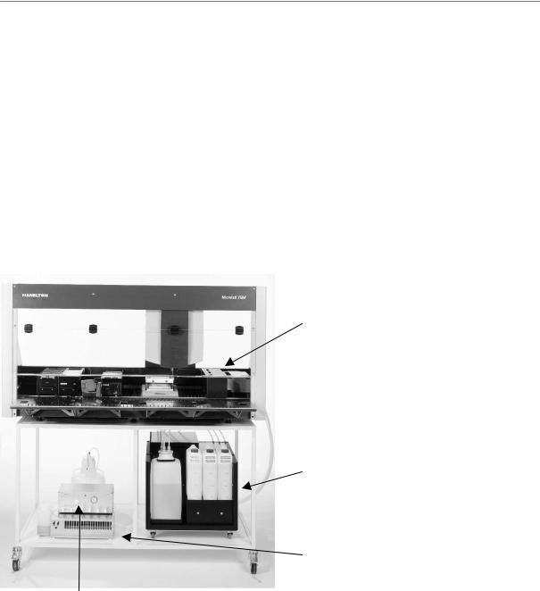
Accessories are defined as additional components that can be ordered later by the customer and installed either by HAMILTON personnel, or by the customer. They include carriers, a wash station, a temperature-controlled carrier and an automatic vacuum system, which are described in this section of the manual. Note that the availability of accessories is subject to change. Please ask for a current list.
Wash Station
Pump Station with 3 wash solutions and waste container
Heat Exchanger for TCC
Controller for
Vacuum Box
7KH 0LFURODE 67$5 ZLWK &DUULHUV :DVK 6WDWLRQ 7HPSHUDWXUH FRQWUROOHG &DUULHU DQG 9DFXXP 6\VWHP
&DUULHUV
The labware is placed on special carriers which are loaded onto the Microlab STAR. HAMILTON provides a wide range of standard carriers for microtiter plates, tubes, tips etc. All standard carriers can be added to the deck by the user.
The naming of carriers follows a systematic nomenclature: ; < = $QQ.
;: stands for the type of labware, placed on the carriers, e.g., TIP (= tips),
PLT (plates), SMP (=samples)
<=CAR for carrier
610766/02 |
Page 27 of 225 |
Microlab® STAR User Manual
=: describes the labware details, e.g.,
/: landscape orientation
3: portrait orientation
1XPEHU: number of items placed on the carrier (plates or tips)
0': medium density (96or 384-well microplates)
+': high density microplates (1536)
$&: 96-well archive plates
$QQ identifies the part number revision (e.g. A00)
([DPSOH PLT-CAR-L5MD-A00 is a carrier for 5 medium density (96or 384-well) microplates in landscape orientation.
A carrier must always be identified (e.g in deck layouts and methods) by the unique descriptor with which it is tagged.
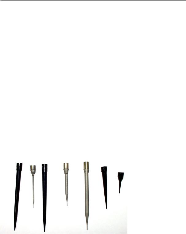
'LVSRVDEOHV
CO-RE tips come in 3 sizes: low-volume, standard, and high-volume (approximately 10, 300, and 1000 l respectively). One blister pack contains 5 racks of 96 tips, giving a total of 480 tips. CO-RE tips are available in boxes of 4000-6000, depending on the tip size. CO-RE tips are produced under sterile conditions, i.e. the tips are RNAseand DNAse-free.
Reusable needles with 50, 300, and 1000 l volumes may be used instead of tips. Only HAMILTON needles and disposable tips should be used for coupling to the pipetting channel of the Microlab STAR.
+$0,/721 VWHHO QHHGOHV DQG GLVSRVDEOH WLSV IRU WKH 0/ 67$5
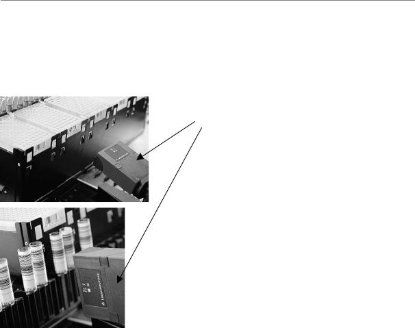
1HHGOH :DVK 6WDWLRQ
The needle wash station is a device for the washing and drying of steel needles parallel to the pipetting process. The wash station has the width of a normal microplate carrier (6T) and is mounted on the deck of the Microlab STAR. All tubing and electrical connections are routed through the docking station at the rear of the instrument. Along with each wash station comes a pump station with three reservoir containers for wash solutions and a waste container. This pump station is placed below the bench on which the Microlab STAR rests.
Page 28 of 225 |
610766/02 |
Microlab® STAR User Manual
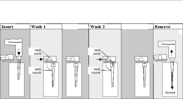
The principle of the wash station is illustrated in the following figure, where a typical procedure is shown.
6RDN |
6RDN 'UDLQ |
6FKHPDWLF GUDZLQJ RI QHHGOH ZDVK SURFHVV 1HHGOHV DUH SODFHG LQWR WKH ZDVK PRGXOH ZDVKHG IURP LQVLGH DQG DORQJ WKH RXWVLGH ZLWK ZDVK DQG ULQVH VROXWLRQ 7KH SLSHWWLQJ FKDQQHOV EORZ DLU WKURXJK WKH QHHGOHV WR H[SHO DQ\ UHVLGXDO OLTXLG IURP WKHP
One wash station consists of three individual 8-fold wash modules IRU WKH VDPH QHHGOH W\SH: High Volume (1000 l), Standard Volume (300 l), or Low Volume (50 l).
To enable parallel pipetting with an 8-channel Microlab STAR, the following cycle of steps takes place:
1.fresh needles are picked up from the first module for pipetting, used, and then placed back into the same module. Washing starts.
2.fresh needles are picked up from the second module for pipetting, used, and then placed back into the same module. Washing starts.
3.fresh needles are picked up from the third module for pipetting, used, and then placed back into the same module. Washing starts.
4.The next set of needles is picked up from the first module again, which in the meantime has washed and dried all 8 needles. The process is repeated again.
The needle wash station needs to be installed by a trained Hamilton engineer.
127(
'R QRW XVH GLVSRVDEOH WLSV ZLWK WKH ZDVK VWDWLRQ 7R XVH WZR GLIIHUHQW QHHGOH W\SHV WZR ZDVK VWDWLRQV RI GLIIHUHQW W\SH DUH QHHGHG
)RU D FKDQQHO LQVWUXPHQW WZR LQGHSHQGHQW ZDVK VWDWLRQV DUH QHFHVVDU\ WR HQDEOH XQLQWHUUXSWHG SLSHWWLQJ ZLWK RQH QHHGOH W\SH
$ PD[LPXP RI ZDVK VWDWLRQV HDFK ZLWK ZDVK PRGXOHV DQG LWV RZQ SXPS VWDWLRQ FDQ EH LQVWDOOHG RQ RQH 0LFURODE 67$5
The carry-over of the wash station depends on the wash program. Typical values are 10-5 to 10-6.
The wash parameters can be set within the User Software, prior to each wash step.
610766/02 |
Page 29 of 225 |
Microlab® STAR User Manual
For each of the two wash solutions (or wash and rinse solution), a set of parameters can be specified:
-The ³ULQVH WLPH´ is the length of time liquid flows through the wash chamber.
-The ³VRDN WLPH´ is the length of time wash liquid is held within the wash chamber.
-The ³IORZ UDWH´ is given in millilitres per second for both wash liquids.
For the drying of needles an additional parameter is used:
-The ³GUDLQLQJ WLPH´ gives the length of time allotted for draining the liquid from the needles.
A set of default parameters is given for the wash process within the relevant dialog boxes of the User Software.
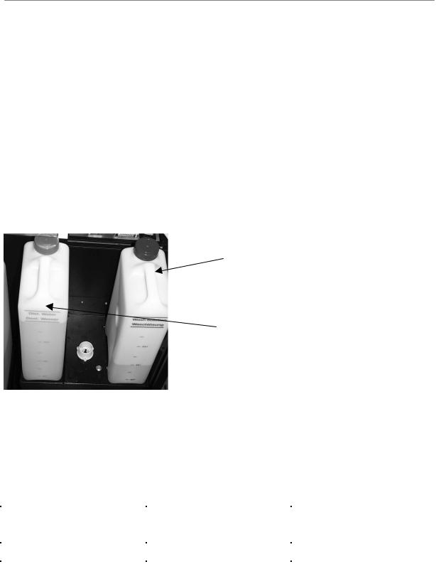
To empty the waste liquid container or to refill the wash solutions, lift the container by the handle. The valve at the bottom automatically closes, sealing the container. To reattach the container, simply slot it back into its original position.
Wash Solution One: red,
2 right-most containers (2 x 3 L)
Wash Solution Two: blue, left-hand container (1 x 3 L)
7KH OLTXLG FRQWDLQHUV RI WKH ZDVK VWDWLRQ 7KH ZDVWH FRQWDLQHU LV SODFHG WR WKH OHIW RI WKH EOXH FRQWDLQHU DQG KDV D YROXPH RI /
Customers can order one of two complete variants of the wash station: “regular“, suitable for most uses, and “chemical-resistant“, specially designed to meet the needs of those working with aggressive chemicals. Each variant is complete with 3 wash modules and pump station. For each variant there are high-, standardand low-volume options. The part numbers for the various options are given in the table below:
|
Regular |
Chemical-Resistant |
Low Vol. |
182575 |
182722 |
Std. Vol. |
182574 |
182721 |
High Vol. |
182573 |
182720 |
127(
$ WDEOH RI FKHPLFDO FRPSDWLELOLWLHV ZLWK WKH ZDVK VWDWLRQ FDQ EH IRXQG LQ DSSHQGL[ ) 7KH LQIRUPDWLRQ OLVWHG LV EDVHG RQ ODERUDWRU\ WHVWV ZLWK UDZ PDWHULDOV DQG VKRXOG EH LQWHUSUHWHG DV D JXLGHOLQH RQO\
Page 30 of 225 |
610766/02 |
 Loading...