


 Loading...
M i c r o l a b F . A . M . E .
S e r v i c e M A N U A L
Version 2.0
P/N 610015
Important Notice:
•Reproduction of any part of this manual in any form whatsoever without the express written consent of Hamilton Bonaduz AG is forbidden.
•The contents of this manual are subject to change without notice.
•All efforts have been made to ensure the accuracy of the contents of this manual. However, should any errors be detected, Hamilton Bonaduz AG would greatly appreciate being informed of them.
•The above notwithstanding, Hamilton Bonaduz AG can assume no responsibility for any errors in this manual or their consequences.
•Copyright ã 1996 Hamilton Bonaduz AG, Bonaduz Switzerland. All Rights Reserved.
•Microlab is a registered trademark of Hamilton Bonaduz AG.
•IBM, OS/2 DATABASE 2 and DB2 are registered trademarks of International Business Machines Corporation.

FAX or MAIL
To: |
Hamilton Bonaduz AG |
Dealer: ................................................................ |
|
Postfach 26 |
............................................................................. |
|
CH-7402 Bonaduz/Switzerland |
|
|
Fax: +41 (81) 37 25 63 |
............................................................................. |
|
*After 16.4.96: +41 (81) 641 25 63 |
|
|
|
|
|
|
Service Technician: ............................................. |
Attn: |
Sales Documentation (VD) |
|
|
|
|
Service Manual Registration
Service manuals must be registered with Hamilton Bonaduz AG to ensure that service technicians receive manual updates and other important service information. The service manual registration number can be found on the inside cover of the manual.
Please complete and send or fax this form to Hamilton Bonaduz AG.
Instrument |
Microlab F.A.M.E. |
Service Manual p/n |
610 015 |
Manual Registration No: ................................... |
|
I hereby confirm that I have received the above mentioned manual.
Service Technician |
Date: ....................................... |
Signature: ........................................................ |
Comments: ...................................................................................................................................................................................................................
..................................................................................................................................................................................................................................................
..................................................................................................................................................................................................................................................
..................................................................................................................................................................................................................................................
——— ML F.A.M.E. Service Manual V2.0 ————————————————————————————————————————— Table of Contents ———
Table of Contents
Chapter |
1 |
SYSTEM ......................................................................................................... |
1-1 |
|
1.1 |
ML F.A.M.E. Instrument ........................................................................... |
1-1 |
|
1.1.1 |
General Information ............................................................................................ |
1-1 |
|
|
Location of Warning and Attention Labels .................................................. |
1-2 |
|
1.1.2 |
Service Concept ................................................................................................... |
1-4 |
|
1.1.2.1 |
General Information ............................................................................................ |
1-4 |
|
1.1.2.2 |
ML F.A.M.E. Service Manual ........................................................................... |
1-4 |
|
1.1.2.2.1 |
Description of text icons .................................................................................... |
1-5 |
|
1.1.2.2.2 |
Updating the Service Manual .......................................................................... |
1-5 |
|
1.1.2.2.3 |
Service Bulletins .................................................................................................. |
1-5 |
|
1.1.2.2.4 |
Service Part Classifications ............................................................................. |
1-5 |
|
1.1.2.2.5 |
Service Assemblies ............................................................................................ |
1-6 |
|
1.1.2.2.6 |
ML F.A.M.E. instruments with CE conformity ............................................ |
1-6 |
|
1.1.2.2.7 |
Pin coding for PCBs ........................................................................................... |
1-7 |
|
1.1.2.2.8 |
Connector numbering ........................................................................................ |
1-7 |
|
1.1.2.3 |
Feedback (Quarterly Service Call Statistics) ............................................. |
1-9 |
|
1.1.2.4 |
Parts Return Tag .................................................................................................. |
1-9 |
|
|
Material Return Good Authorization ............................................................. |
1-9 |
|
1.1.2.5 |
Technical Data Sheet ......................................................................................... |
1-9 |
|
1.1.2.6 |
Service Kit ........................................................................................................... |
1-10 |
|
1.1.2.6.1 |
Service Kit Spare Parts List .......................................................................... |
1-10 |
|
1.1.2.6.2 |
Service PCB (to be used with Diagnostic Master) ............................... |
1-13 |
|
1.1.3 |
F.A.M.E. Description ........................................................................................ |
1-15 |
|
1.1.3.1 |
Purpose of the system .................................................................................... |
1-16 |
|
1.1.3.2 |
General Operation Procedure ...................................................................... |
1-16 |
|
1.1.3.3 |
F.A.M.E configurations .................................................................................... |
1-17 |
|
1.1.3.3.1 |
Overview .............................................................................................................. |
1-17 |
|
1.1.3.3.2 |
Configuration 16/20 ......................................................................................... |
1-19 |
|
1.1.3.3.3 |
Configuration 16/30 ......................................................................................... |
1-27 |
|
1.1.3.3.4 |
Configuration 24/20 ......................................................................................... |
1-35 |
|
1.1.3.3.5 |
Configuration 24/30 ......................................................................................... |
1-43 |
|
1.1.3.3.6 |
OEM specific Part Numbers ......................................................................... |
1-51 |
|
1.1.3.3.7 |
Exchange Modules and Exchange Module Parts Lists ...................... |
1-52 |
|
1.1.3.3.8 |
Expansion Modules and Expansion Module Parts Lists .................... |
1-55 |
|
1.1.3.3.9 |
Shipping Kits ...................................................................................................... |
1-67 |
|
1.1.4 |
Microlab F.A.M.E. Installation ....................................................................... |
1-69 |
p/n 610 015 |
i |
——— ML F.A.M.E. Service Manual V2.0 ———————————————————————————————————————— Table of Contents ———
1.1.4.1 |
Workplace environment .................................................................................. |
1-69 |
1.1.4.2 |
Unpacking Microlab F.A.M.E. ....................................................................... |
1-71 |
|
Adjust chassis to instrument configuration .............................................. |
1-72 |
1.1.4.3 |
Instrument assembly ....................................................................................... |
1-74 |
1.1.4.3.1 |
Installing INCUBATOR Module ................................................................... |
1-74 |
1.1.4.3.2 |
Installing WASHER/DISPENSER Module ............................................... |
1-76 |
1.1.4.3.3 |
Installing ENTRY Module .............................................................................. |
1-78 |
1.1.4.3.4 |
Installing END Module .................................................................................... |
1-79 |
1.1.4.3.5 |
Installing Main Shuttle Rail & Panels ........................................................ |
1-80 |
1.1.4.3.6 |
Installing Container Stack .............................................................................. |
1-86 |
1.1.4.3.7 |
Connecting Tubing and Cables ................................................................... |
1-87 |
1.1.4.3.8 |
Installing Reagent Container Carousel ..................................................... |
1-90 |
1.1.4.3.9 |
Computer Installation ...................................................................................... |
1-91 |
1.1.4.3.10 |
Electrical Installation ........................................................................................ |
1-92 |
1.1.4.3.11 |
Software Installation ........................................................................................ |
1-92 |
1.1.4.3.12 |
Login and Access ............................................................................................. |
1-92 |
1.1.4.3.13 |
System Start-up and Shut-down ................................................................. |
1-93 |
1.1.4.3.14 |
Downloading Firmware to Instrument ....................................................... |
1-94 |
1.1.4.3.15 |
Installing Filter Case ........................................................................................ |
1-96 |
1.1.4.3.16 |
Loading Check Plate into Instrument ........................................................ |
1-97 |
1.1.4.3.17 |
Instrument Calibration ..................................................................................... |
1-98 |
|
Rotor Calibration Pin ....................................................................................... |
1-99 |
1.1.5 |
Instrument Disassembly .............................................................................. |
1-101 |
1.1.5.1 |
Instrument shut down ................................................................................... |
1-101 |
1.1.5.1.1 |
Removing the Photometer Filter Case .................................................. |
1-101 |
1.1.5.1.2 |
Removing MTPs and Check Plates ........................................................ |
1-102 |
1.1.5.1.3 |
Decontamination ............................................................................................ |
1-102 |
1.1.5.1.4 |
Draining the washer system ...................................................................... |
1-103 |
1.1.5.2 |
Preparing Modules for Disassembly ....................................................... |
1-103 |
1.1.5.3 |
Disassembly .................................................................................................... |
1-105 |
1.1.5.3.1 |
Removing Container Stack ........................................................................ |
1-106 |
1.1.5.3.2 |
Removing Panels & Main Shuttle Rail ................................................... |
1-108 |
1.1.5.3.3 |
Handling and Removal of Modules .......................................................... |
1-111 |
1.1.6 |
Packing F.A.M.E. for Shipment .................................................................. |
1-117 |
1.1.7 |
Exchange Modules ........................................................................................ |
1-125 |
1.1.8 |
Expansion Modules ....................................................................................... |
1-126 |
1.1.9 |
Decontamination ............................................................................................ |
1-127 |
1.1.10 |
Maintenance .................................................................................................... |
1-127 |
1.1.10.1 |
General maintenance ................................................................................... |
1-127 |
1.1.10.2 |
Half Yearly Maintenance / Service .......................................................... |
1-128 |
ii
——— ML F.A.M.E. Service Manual V2.0 ————————————————————————————————————————— Table of Contents ———
|
1.1.10.2.1 |
Tasks .................................................................................................................. |
1-128 |
|
1.1.10.2.2 |
Running Macros for Half Yearly Maintenance/Service .................... |
1-128 |
|
1.1.10.2.3 |
Macros Available for Maintenance/Service .......................................... |
1-129 |
|
1.1.10.3 |
Preventive maintenance .............................................................................. |
1-130 |
|
1.2 |
Microlab AT / AT plus / AT plus 2 ........................................... |
1-135 |
|
1.3 |
F.A.M.E. Software ................................................................................. |
1-139 |
|
1.3.1 |
Personal Computer Requirements .......................................................... |
1-139 |
|
1.3.2 |
ML F.A.M.E. System Requirements ........................................................ |
1-139 |
|
1.3.3 |
Software Requirements ............................................................................... |
1-139 |
|
1.3.4 |
Microlab F.A.M.E. Software Specifications ........................................... |
1-140 |
|
1.3.5 |
Connections to Sample Preparation Instruments .............................. |
1-140 |
|
1.3.6 |
Overview ........................................................................................................... |
1-141 |
|
1.3.7 |
Diagnostic Master .......................................................................................... |
1-142 |
|
1.3.8 |
How to run macros ........................................................................................ |
1-143 |
|
1.4 |
Totally Integrated ML F.A.M.E System ............................... |
1-147 |
Chapter |
2 |
ENTRY MODULE ............................................................................... |
2-7 |
|
2.1 |
Entry Module Raw ..................................................................................... |
2-7 |
|
2.1.1 |
Design ...................................................................................................................... |
2-7 |
|
2.1.2 |
Wiring Diagram Entry Module Raw: ............................................................. |
2-9 |
|
2.1.3 |
Functional Description Entry Module ......................................................... |
2-10 |
|
2.1.4 |
Calibration, adjusting ........................................................................................ |
2-11 |
|
2.1.5 |
Removing Entry Module .................................................................................. |
2-11 |
|
2.1.6 |
Removing Assemblies .................................................................................... |
2-12 |
|
2.1.6.1 |
Entry lift ................................................................................................................ |
2-14 |
|
2.1.6.2 |
Inc. tower - amb. temp., contr. temp. & Inc. tower lift ........................... |
2-16 |
|
2.1.6.3 |
Mains power unit ............................................................................................... |
2-20 |
|
2.1.7 |
Replacing spare parts ..................................................................................... |
2-21 |
|
2.1.7.1 |
Cables E1, E2, E7, and E8 ............................................................................ |
2-21 |
|
2.1.7.2 |
Cables E4, E5 and E6 ..................................................................................... |
2-22 |
|
2.1.7.3 |
Cable E20 ............................................................................................................ |
2-23 |
|
2.1.7.4 |
Connector board E11 & cable E22 ............................................................. |
2-24 |
|
2.1.8 |
Reader complete .............................................................................................. |
2-27 |
|
2.1.8.1 |
Functional Description .................................................................................... |
2-27 |
|
2.1.8.2 |
Wiring Diagram Reader Complete ............................................................. |
2-27 |
|
2.1.8.3 |
Replacing reader complete ........................................................................... |
2-28 |
|
2.1.9 |
Spare Parts List ................................................................................................. |
2-29 |
|
2.1.10 |
3D Drawings ....................................................................................................... |
2-30 |
|
2.1.11 |
Troubleshooting ................................................................................................. |
2-33 |
iii
——— ML F.A.M.E. Service Manual V2.0 ———————————————————————————————————————— Table of Contents ———
2.2 |
Entry Module Frame ............................................................................ |
2-39 |
2.2.1 |
Functional Description .................................................................................... |
2-39 |
2.2.2 |
Connector boards ............................................................................................. |
2-40 |
2.2.3 |
MTP (Micro Titer Plate)-Sensor (block diagram).................................... |
2-46 |
2.2.4 |
Module Transport Assembly (wiring diagram)......................................... |
2-46 |
2.2.5 |
Replacing spare parts ..................................................................................... |
2-49 |
2.2.5.1 |
Connector board E1 ........................................................................................ |
2-49 |
2.2.5.2 |
Connector board E5 ........................................................................................ |
2-50 |
2.2.5.3 |
Connector board E2 ........................................................................................ |
2-50 |
2.2.5.4 |
Temperature sensor, tower fan (front) ...................................................... |
2-51 |
2.2.5.5 |
Tower fan (rear) ................................................................................................. |
2-52 |
2.2.5.6 |
Connector boards E6 and E7 ....................................................................... |
2-53 |
2.2.5.7 |
Connector board E13 ...................................................................................... |
2-54 |
2.2.5.8 |
Step motor, and gear belt .............................................................................. |
2-55 |
2.2.5.9 |
Gear belt .............................................................................................................. |
2-56 |
2.2.5.10 |
Connector board E10 ...................................................................................... |
2-58 |
2.2.5.11 |
Connector board E9 ........................................................................................ |
2-58 |
2.2.5.12 |
Cable E9 .............................................................................................................. |
2-59 |
2.2.6 |
Spare Parts List ................................................................................................. |
2-60 |
2.2.7 |
3D Drawing Entry Frame ............................................................................... |
2-63 |
2.2.8 |
Troubleshooting ................................................................................................. |
2-65 |
2.3 |
Entry Lift ......................................................................................................... |
2-73 |
2.3.1 |
Functional Description .................................................................................... |
2-73 |
2.3.2 |
Connector Boards ............................................................................................. |
2-74 |
2.3.3 |
Wiring Diagram .................................................................................................. |
2-76 |
2.3.4 |
Replacing Spare Parts .................................................................................... |
2-77 |
2.3.4.1 |
Range flag ........................................................................................................... |
2-77 |
2.3.4.2 |
Connector board E14 ...................................................................................... |
2-78 |
2.3.4.3 |
Step motor, and belt ........................................................................................ |
2-79 |
2.3.4.4 |
Thrust bearing and thrust washer ............................................................... |
2-80 |
2.3.4.5 |
Lift nut ................................................................................................................... |
2-80 |
2.3.4.6 |
Tension spring .................................................................................................... |
2-82 |
2.3.5 |
Spare Parts List ................................................................................................. |
2-83 |
2.3.6 |
3D Drawing Entry Lift ...................................................................................... |
2-85 |
2.3.7 |
Troubleshooting ................................................................................................. |
2-87 |
2.3 |
Incubator Towers .................................................................................... |
2-93 |
2.3.1 |
Incubator Tower Ambient Temp. .................................................................. |
2-93 |
2.3.1.1 |
Functional Description .................................................................................... |
2-93 |
2.3.1.2 |
Block Diagram .................................................................................................... |
2-93 |
2.3.1.3 |
Connector Board ............................................................................................... |
2-93 |
iv
——— ML F.A.M.E. Service Manual V2.0 ————————————————————————————————————————— Table of Contents ———
2.3.1.4 |
Wiring Diagram .................................................................................................. |
2-93 |
2.3.1.5 |
3D Drawing ......................................................................................................... |
2-93 |
2.3.1.6 |
Replacing Spare Parts .................................................................................... |
2-93 |
2.3.1.7 |
Spare Parts List ................................................................................................. |
2-94 |
2.3.2 |
Incubator Tower Controlled Temp. ............................................................. |
2-95 |
2.3.2.1 |
Functional Description .................................................................................... |
2-95 |
2.3.2.2 |
Connector Board ............................................................................................... |
2-96 |
2.3.2.3 |
Wiring Diagram .................................................................................................. |
2-98 |
2.3.2.4 |
Replacing Spare Parts ................................................................................. |
2-101 |
2.3.2.4.1 |
How to remove an incubation slot ........................................................... |
2-101 |
2.3.2.4.2 |
Over temperature switch ............................................................................. |
2-102 |
2.3.2.4.3 |
Cable E22, temperature sensor ............................................................... |
2-103 |
2.3.2.4.4 |
Heating element ............................................................................................. |
2-104 |
2.3.2.5 |
Spare Parts List .............................................................................................. |
2-105 |
2.3.3 |
3D Drawing Incubator Tower Controlled ................................................ |
2-106 |
2.3.4 |
Troubleshooting .............................................................................................. |
2-107 |
2.5 |
Incubator Tower Lift ........................................................................... |
2-117 |
2.5.1 |
Functional Description .................................................................................. |
2-117 |
2.5.2 |
Connector Boards ........................................................................................... |
2-118 |
2.5.3 |
Wiring Diagram ................................................................................................ |
2-119 |
2.5.4 |
Replacing Spare Parts ................................................................................. |
2-120 |
2.5.4.1 |
Stepper motor E SM20 and / or gear belt ............................................. |
2-120 |
2.5.4.2 |
Thrust bearing, thrust washer ................................................................... |
2-121 |
2.5.4.3 |
Connector board E12 ................................................................................... |
2-122 |
2.5.4.4 |
Flag ..................................................................................................................... |
2-123 |
2.5.5 |
Spare Parts List .............................................................................................. |
2-124 |
2.5.6 |
3D Drawing Incubator Tower Lift .............................................................. |
2-126 |
2.5.7 |
Troubleshooting .............................................................................................. |
2-127 |
2.6 |
Mains Power Unit ................................................................................. |
2-133 |
2.6.1 |
Functional Description ................................................................................. |
2-133 |
2.6.2 |
Connector Board ............................................................................................ |
2-134 |
2.6.3 |
Wiring Diagram ............................................................................................... |
2-135 |
2.6.4 |
Replacing Spare Parts ................................................................................. |
2-136 |
2.6.5 |
Spare Parts List .............................................................................................. |
2-136 |
2.6.6 |
3D Drawing Mains Power Unit .................................................................. |
2-138 |
2.7 |
Entry Module Electronic Rack .................................................. |
2-143 |
2.7.1 |
Motherboard E PCB ..................................................................................... |
2-144 |
2.7.2 |
Power Supply 1 PCB .................................................................................... |
2-145 |
2.7.3 |
Processors PCB 1, PCB 2, PCB 3 .......................................................... |
2-151 |
2.7.4 |
Stepper Motor PCB ....................................................................................... |
2-159 |
v
——— ML F.A.M.E. Service Manual V2.0 ———————————————————————————————————————— Table of Contents ———
|
2.7.5 |
Entry PCB ......................................................................................................... |
2-165 |
|
2.7.6 |
Incubator PCB ................................................................................................ |
2-171 |
Chapter |
3 |
INCUBATOR MODULE .............................................................. |
3-7 |
|
3.1 |
Incubator Module Raw .......................................................................... |
3-7 |
|
3.1.1 |
Design ...................................................................................................................... |
3-7 |
|
3.1.2 |
Wiring Diagram Inc. Module Raw .................................................................. |
3-9 |
|
3.1.3 |
Functional Description Incubator Module ................................................ |
3-10 |
|
3.1.4 |
Calibration, Adjusting ...................................................................................... |
3-10 |
|
3.1.5 |
Removing Incubator Module .......................................................................... |
3-11 |
|
3.1.6 |
Removing Assemblies ..................................................................................... |
3-11 |
|
3.1.7 |
Replacing Spare Parts ..................................................................................... |
3-11 |
|
3.1.8 |
Spare Parts List .................................................................................................. |
3-11 |
|
3.1.9 |
3D Drawings ....................................................................................................... |
3-12 |
|
3.1.10 |
Troubleshooting ................................................................................................. |
3-15 |
|
3.2 |
Incubator Module Frame .................................................................. |
3-21 |
|
3.2.1 |
Functional Description .................................................................................... |
3-21 |
|
3.2.2 |
Connector Boards ............................................................................................. |
3-22 |
|
3.2.3 |
Replacing Spare Parts .................................................................................... |
3-23 |
|
3.2.4 |
Spare Parts List ................................................................................................. |
3-23 |
|
3.2.5 |
3D Drawings ....................................................................................................... |
3-26 |
|
3.2.6 |
Troubleshooting ................................................................................................. |
3-29 |
Chapter |
4 |
WASHER / DISPENSER ........................................................... |
4-7 |
|
4.1 |
Washer / Dispenser Module Raw ................................................ |
4-7 |
|
4.1.1 |
Design ...................................................................................................................... |
4-7 |
|
4.1.2 |
Functional Description W / D Module ........................................................ |
4-10 |
|
4.1.3 |
Removing Washer / Dispenser Module ..................................................... |
4-11 |
|
4.1.4 |
Removing Assemblies .................................................................................... |
4-12 |
|
4.1.4.1 |
Dispenser ........................................................................................................... |
4-13 |
|
4.1.4.2 |
Reagent Drawer ................................................................................................ |
4-14 |
|
4.1.4.3 |
Washer Lift .......................................................................................................... |
4-16 |
|
4.1.4.4 |
External pump station .................................................................................... |
4-18 |
|
4.1.5 |
Replacing Spare Parts .................................................................................... |
4-19 |
|
4.1.5.1 |
Motherboard W/D PCB ................................................................................... |
4-19 |
|
4.1.5.2 |
DC motor W PM 70 ......................................................................................... |
4-19 |
|
4.1.5.3 |
AC motor W PM 80 .......................................................................................... |
4-21 |
|
4.1.5.4 |
Cable W32 .......................................................................................................... |
4-21 |
|
4.1.5.5 |
Water separator ................................................................................................. |
4-22 |
vi
——— ML F.A.M.E. Service Manual V2.0 ————————————————————————————————————————— Table of Contents ———
4.1.8 |
Fluid-Flow Diagram ......................................................................................... |
4-27 |
4.1.9 |
Troubleshooting ................................................................................................. |
4-28 |
4.2 |
Washer / Dispenser Module Frame ........................................ |
4-35 |
4.2.1 |
Functional Description .................................................................................... |
4-35 |
4.2.2 |
Connector Boards ............................................................................................. |
4-36 |
4.2.3 |
Wiring Diagram Washer Pumps .................................................................. |
4-42 |
4.2.4 |
Replacing spare parts ..................................................................................... |
4-43 |
4.2.4.1 |
Connector board I1 PCB ................................................................................ |
4-43 |
4.2.4.2 |
Connector board W8 PCB ............................................................................. |
4-44 |
4.2.4.3 |
Connector board W11 PCB .......................................................................... |
4-45 |
4.2.4.4 |
Connector board W13 PCB and seal ........................................................ |
4-46 |
4.2.4.5 |
Cable W50 .......................................................................................................... |
4-47 |
4.2.4.6 |
Cable W43 .......................................................................................................... |
4-48 |
4.2.4.7 |
Step motor W SE10 ......................................................................................... |
4-49 |
4.2.4.8 |
Gear belt open ................................................................................................... |
4-50 |
4.2.4.9 |
Gear belt MXL .................................................................................................... |
4-51 |
4.2.5 |
Spare Parts List ................................................................................................. |
4-53 |
4.2.6 |
3D Drawing Washer / Dispenser Frame .................................................. |
4-55 |
4.2.7 |
Troubleshooting ................................................................................................. |
4-56 |
4.3 |
Dispenser ...................................................................................................... |
4-61 |
4.3.1 |
Functional Description .................................................................................... |
4-61 |
4.3.2 |
Connector Boards ............................................................................................. |
4-63 |
4.3.3 |
Wiring Diagram .................................................................................................. |
4-67 |
4.3.4 |
Replacing spare parts ..................................................................................... |
4-71 |
4.3.4.1 |
Connector board W9 PCB and cable W8 ................................................ |
4-71 |
4.3.4.2 |
Step motor W SE30 and Gear belt MXL .................................................. |
4-74 |
4.3.4.3 |
Regulating screw 2 compl. ............................................................................ |
4-75 |
4.3.4.4 |
Guide bush (on guide shaft 3) ...................................................................... |
4-75 |
4.3.4.5 |
Guide bush (on guide shaft 5) ...................................................................... |
4-77 |
4.3.4.6 |
Step motor W SM25 and step motor W SE20 ....................................... |
4-78 |
4.3.4.7 |
Gear belt MXL and Gear belt ....................................................................... |
4-79 |
4.3.4.8 |
Gear belt .............................................................................................................. |
4-81 |
4.3.4.9 |
Connector board W6 PCB ............................................................................. |
4-84 |
4.3.4.10 |
Regulating screw 1 compl. ............................................................................ |
4-86 |
4.3.4.11 |
Connector board W5 PCB ............................................................................. |
4-86 |
4.3.4.12 |
Cable W7 ............................................................................................................. |
4-87 |
4.3.5 |
Spare Parts List ................................................................................................. |
4-89 |
4.3.6 |
3D Drawings ....................................................................................................... |
4-92 |
4.3.7 |
Troubleshooting ................................................................................................. |
4-94 |
vii
——— ML F.A.M.E. Service Manual V2.0 ———————————————————————————————————————— Table of Contents ———
4.4 |
Reagent Drawer .................................................................................... |
4-103 |
4.4.1 |
Functional Description ................................................................................. |
4-103 |
4.4.2 |
Connector Boards .......................................................................................... |
4-104 |
4.4.3 |
Wiring Diagram ................................................................................................ |
4-110 |
4.4.4 |
Replacing spare parts ................................................................................... |
4-113 |
4.4.4.1 |
Connector board W1 PCB ........................................................................... |
4-113 |
4.4.4.2 |
Reagent carousel support ........................................................................... |
4-114 |
4.4.4.3 |
Contact spring .................................................................................................. |
4-115 |
4.4.4.4 |
Step motor W SE40, Gear belts ................................................................ |
4-116 |
4.4.4.5 |
Connector board W4 PCB ........................................................................... |
4-117 |
4.4.4.6 |
Barcode reader BR45 ................................................................................... |
4-118 |
4.4.4.7 |
Connector board W2 PCB ........................................................................... |
4-119 |
4.4.4.8 |
Hall effect micro switch drawer access Cable W14 .......................... |
4-120 |
4.4.4.9Hall effect micro switch drawer end position
|
Cable W15 ........................................................................................................ |
4-120 |
4.4.4.10 |
Cable W12 ....................................................................................................... |
4-121 |
4.4.4.11 |
Drawer compartment .................................................................................... |
4-121 |
4.4.5 |
Spare Parts List .............................................................................................. |
4-122 |
4.4.6 |
3D Drawing Reagent Drawer .................................................................... |
4-124 |
4.4.7 |
Troubleshooting .............................................................................................. |
4-125 |
4.5 |
Washer Lift ................................................................................................ |
4-133 |
4.5.1 |
Functional Description ................................................................................. |
4-133 |
4.5.2 |
Connector Boards .......................................................................................... |
4-134 |
4.5.3 |
Wiring Diagram ............................................................................................... |
4-141 |
4.5.4 |
Replacing spare parts .................................................................................. |
4-145 |
4.5.4.1 |
Step motor W SM50, Gear belts .............................................................. |
4-145 |
|
Gear belts: ........................................................................................................ |
4-146 |
4.5.4.2 |
Manifold coupling compl. ............................................................................ |
4-148 |
4.5.4.3 |
Shell spring ...................................................................................................... |
4-150 |
4.5.4.4 |
Wash shell ........................................................................................................ |
4-152 |
4.5.4.5 |
Connector board W12 PCB ....................................................................... |
4-152 |
4.5.4.6 |
Connector board W14 PCB ....................................................................... |
4-153 |
4.5.4.7 |
Connector board W16 PCB ....................................................................... |
4-154 |
4.5.4.8 |
Cable W44 ........................................................................................................ |
4-154 |
4.5.5 |
Manifold Complete ........................................................................................ |
4-155 |
4.5.6 |
Spare Parts List .............................................................................................. |
4-156 |
4.5.7 |
3D Drawing Washer Lift .............................................................................. |
4-158 |
4.5.8 |
Troubleshooting .............................................................................................. |
4-159 |
4.6 |
External Pump Station .................................................................... |
4-167 |
4.6.1 |
Functional Description ................................................................................. |
4-167 |
viii
——— ML F.A.M.E. Service Manual V2.0 ————————————————————————————————————————— Table of Contents ———
|
4.6.2 |
External Pump Station PCB ....................................................................... |
4-168 |
|
4.6.3 |
Wiring Diagram External Pump Station ................................................. |
4-174 |
|
4.6.4 |
Replacing spare parts .................................................................................. |
4-175 |
|
4.6.4.1 |
Removing and remounting of PCB cover ............................................. |
4-175 |
|
4.6.4.2 |
Silicone Tubing ............................................................................................... |
4-175 |
|
4.6.4.3 |
DC motor W PM61 ........................................................................................ |
4-176 |
|
4.6.4.4 |
External pump station PCB ........................................................................ |
4-176 |
|
4.6.4.5 |
Wash fluid level sensor ............................................................................... |
4-177 |
|
4.6.4.6 |
Cable W61 ....................................................................................................... |
4-178 |
|
4.6.4.7 |
O-ring ................................................................................................................. |
4-178 |
|
4.6.4.8 |
O-Rings, Float, Compression Springs ................................................... |
4-179 |
|
4.6.4.9 |
EPROM ............................................................................................................. |
4-180 |
|
4.6.5 |
Spare Parts List .............................................................................................. |
4-181 |
|
4.6.6 |
3D Drawing External Pump Station ........................................................ |
4-183 |
|
4.6.7 |
Troubleshooting .............................................................................................. |
4-184 |
|
4.7 |
W/D Electronic Rack ......................................................................... |
4-191 |
|
4.7.1 |
Motherboard W / D PCB ............................................................................. |
4-192 |
|
4.7.2 |
Power Supply 2 PCB .................................................................................... |
4-193 |
|
4.7.3 |
Processor 2 PCB ........................................................................................... |
4-194 |
|
4.7.4 |
Processor 3 PCB ........................................................................................... |
4-194 |
|
4.7.5 |
Stepper Motor PCB ....................................................................................... |
4-194 |
|
4.7.6 |
Dispenser PCB ............................................................................................... |
4-195 |
|
4.7.7 |
Washer PCB ................................................................................................... |
4-201 |
Chapter |
5 |
END MODULE ........................................................................................ |
5-7 |
|
5.1 |
End Module Raw ........................................................................................ |
5-7 |
|
5.1.1 |
Design ...................................................................................................................... |
5-7 |
|
5.1.2 |
Functional Description End Module .............................................................. |
5-9 |
|
5.1.3 |
Calibration, Adjusting ......................................................................................... |
5-9 |
|
5.1.4 |
Removing End Module ................................................................................... |
5-10 |
|
5.1.5 |
Removing Assemblies ..................................................................................... |
5-11 |
|
5.1.5.1 |
Dispenser ............................................................................................................ |
5-12 |
|
5.1.5.2 |
Reagent drawer ................................................................................................. |
5-13 |
|
5.1.5.3 |
Build-in Photometer ......................................................................................... |
5-13 |
|
5.1.5.4 |
Exit Stack ............................................................................................................. |
5-13 |
|
5.1.6 |
Replacing Spare Parts .................................................................................... |
5-14 |
|
5.1.6.1 |
Pause Button ...................................................................................................... |
5-14 |
|
5.1.7 |
Spare Parts List ................................................................................................. |
5-15 |
|
5.1.8 |
3D Drawings End Module Raw .................................................................... |
5-16 |
ix
——— ML F.A.M.E. Service Manual V2.0 ———————————————————————————————————————— Table of Contents ———
5.1.9 |
Troubleshooting End Raw/ End Dispenser/ End Drawer ................... |
5-19 |
5.2 |
End Module Frame ................................................................................ |
5-31 |
5.2.1 |
Functional Description .................................................................................... |
5-31 |
5.2.2 |
Connector Boards ............................................................................................. |
5-33 |
5.2.3 |
Wiring Diagram .................................................................................................. |
5-37 |
5.2.4 |
Replacing spare parts ..................................................................................... |
5-41 |
5.2.4.1 |
Connector board P1 PCB .............................................................................. |
5-41 |
5.2.4.2 |
Connector board W8 PCB ............................................................................. |
5-41 |
5.2.4.3 |
Connector board P7 PCB .............................................................................. |
5-42 |
5.2.4.4 |
Connector board P8 PCB .............................................................................. |
5-42 |
5.2.4.5 |
Step motor P SE01 .......................................................................................... |
5-43 |
5.2.4.6 |
Step motor W SE10 ......................................................................................... |
5-43 |
5.2.4.7 |
Gear belt .............................................................................................................. |
5-44 |
5.2.4.8 |
Gear belt (module transport) ........................................................................ |
5-45 |
5.2.4.9 |
Gear belt (main shuttle drive) ....................................................................... |
5-46 |
5.2.5 |
Spare Parts List ................................................................................................. |
5-49 |
5.2.6 |
3D Drawing End Module Frame .................................................................. |
5-51 |
5.2.7 |
Troubleshooting ................................................................................................. |
5-52 |
5.3 |
Built-in Photometer .............................................................................. |
5-59 |
5.3.1 |
Functional Description .................................................................................... |
5-59 |
5.3.2 |
Connector Boards ............................................................................................. |
5-60 |
5.3.3 |
Wiring Diagram .................................................................................................. |
5-60 |
5.3.4 |
Replacing Spare Parts .................................................................................... |
5-63 |
5.3.4.1 |
Filter case, filter strip ....................................................................................... |
5-63 |
5.3.4.2 |
Photometer processor PCB .......................................................................... |
5-64 |
5.3.4.3 |
Lamp controller PCB ....................................................................................... |
5-64 |
5.3.4.4 |
Lamp-assembly PCB ....................................................................................... |
5-65 |
5.3.4.5 |
Photometer fan .................................................................................................. |
5-66 |
5.3.4.6 |
Cables P20, P21, P23 and P24 ................................................................. |
5-67 |
5.3.4.7 |
Optical device ..................................................................................................... |
5-68 |
5.3.4.8 |
Connector board P20 ..................................................................................... |
5-70 |
5.3.4.9 |
Photometer air filter .......................................................................................... |
5-70 |
5.3.4.10 |
Step motor ........................................................................................................... |
5-71 |
5.3.4.11 |
Filter case belt ................................................................................................... |
5-73 |
5.3.4.12 |
A/D converter PCB ........................................................................................... |
5-75 |
5.3.4.13 |
Protective glass ................................................................................................. |
5-77 |
5.3.5 |
Spare Parts List ................................................................................................. |
5-79 |
5.3.6 |
Photometer Filter Order List: ........................................................................ |
5-79 |
5.3.7 |
Troubleshooting ................................................................................................. |
5-80 |
x
——— ML F.A.M.E. Service Manual V2.0 ————————————————————————————————————————— Table of Contents ———
5.4 |
Exit Stack ...................................................................................................... |
5-87 |
5.4.1 |
Functional Description .................................................................................... |
5-87 |
5.4.3 |
Wiring Diagram .................................................................................................. |
5-96 |
5.4.4 |
Replacing Spare Parts .................................................................................... |
5-99 |
5.4.4.1 |
Connector board P2 ........................................................................................ |
5-99 |
5.4.4.2 |
Connector board P3 ..................................................................................... |
5-100 |
5.4.4.3 |
Connector board P4 ..................................................................................... |
5-101 |
5.4.4.4 |
Connector board P5 ..................................................................................... |
5-102 |
5.4.4.5 |
Connector board P6 ..................................................................................... |
5-103 |
5.4.4.6 |
Transparent cover sensor .......................................................................... |
5-103 |
5.4.4.7 |
Step motor, gear belt .................................................................................... |
5-105 |
5.4.4.8 |
Connector board P9 ..................................................................................... |
5-106 |
5.4.4.9 |
Gear belt ........................................................................................................... |
5-107 |
5.4.5 |
Spare Parts List .............................................................................................. |
5-108 |
5.4.6 |
3D Drawing Exit Stack .................................................................................. |
5-110 |
5.4.7 |
Troubleshooting ............................................................................................... |
5-111 |
|
5.5 |
Electronic Rack ...................................................................................... |
5-118 |
|
5.5.1 |
Motherboard P PCB ...................................................................................... |
5-119 |
|
5.5.2 |
Power Supply 2 PCB .................................................................................... |
5-120 |
|
5.5.3 |
Processor 1 PCB ........................................................................................... |
5-120 |
|
5.5.4 |
Processor 2 PCB ........................................................................................... |
5-120 |
|
5.5.5 |
Processor 3 PCB ........................................................................................... |
5-120 |
|
5.5.6 |
Stepper Motor PCB ....................................................................................... |
5-120 |
|
5.5.7 |
Dispenser PCB ............................................................................................... |
5-120 |
|
5.5.8 |
Exit PCB ............................................................................................................ |
5-121 |
Chapter |
6 |
INSTRUMENT FRAMEWORK .......................................... |
6-7 |
|
6.1 |
Instrument Error Codes ....................................................................... |
6-7 |
|
6.1.1 |
Entry System ......................................................................................................... |
6-7 |
|
6.1.2 |
Incubator System ................................................................................................. |
6-9 |
|
6.1.3 |
Dispenser System ............................................................................................. |
6-11 |
|
6.1.4 |
Washer System ................................................................................................. |
6-13 |
|
6.1.5 |
Exit System ......................................................................................................... |
6-15 |
|
6.1.6 |
Communication System ................................................................................. |
6-16 |
|
6.1.7 |
Photometer System ......................................................................................... |
6-17 |
|
6.2 |
Container Stack ........................................................................................ |
6-23 |
|
6.3 |
Chassis ............................................................................................................ |
6-31 |
|
6.4 |
Main Shuttle Rail ................................................................................... |
6-45 |
|
6.5 |
Transparent Cover ................................................................................. |
6-55 |
|
6.6 |
Waste Cap ..................................................................................................... |
6-63 |
xi
——— ML F.A.M.E. Service Manual V2.0 ————————————————————————————————————————————— SYSTEM ———
CHAPTER 1 SYSTEM
1.1ML F.A.M.E. Instrument
1.1.1General Information
Refer to User Manual Chapter 1.
ATTENTION
Read Chapter 1, General Instructions, of the User Manual before repairing / servicing the system.
For specific Service Information read section 1.1.2 Service Concept.
ATTENTION
Never lift a fully installed (assembled) instrument from one work bench to another. It must first be dismantled and then reinstalled on the new work bench.
1-1
——— ML F.A.M.E. Service Manual V2.0 ———————————————————————————————————————————— SYSTEM ———
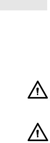
Location of Warning and Attention Labels
Attention: Do not swap plates after loading
Power 


Serial No.
CE Label
PAUSE
(Pause Button)
Warning: 

 Laser Beam
Do Not Stare Into Beam! |
Warning: |
BIOHAZARD |
Class 2 Laser |
Attention: Shut down OS/2 before switching off PC.
Do not change the OS/2 system time during a run.
Warning: |
|
Moving Parts |
|
|
|
Attention: Turn carousel until it drops into locked position. Ensure all plungers are pushed down and caps are properly closed.
Before removing the module decontaminate the instrument, unplug all the connectors and seal the fluid system as described in the manual.
Attention: Close the reagent drawer gently to prevent spillage. Do not fill containers above the “max. 100 ml” mark.
1-2
——— ML F.A.M.E. Service Manual V2.0 ————————————————————————————————————————————— SYSTEM ———
Power Connection:
Connect only to earth grounded outlet
115V~/...A 60Hz
230V~/...A 50Hz
The pause button should generally not be pressed unless instructed by the user software as plate processing may be interrupted leading to aborted plate. Carefully follow the software instructions.
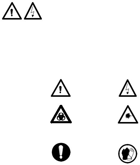
Warning Symbols
General |
Danger |
Warning |
High Voltage |
BIOHAZARD |
Danger |
|
Laser |
||
HANDLE WITH CARE |
||
|
Command Symbols
General |
Wear |
Command |
Gloves |
1-3

——— ML F.A.M.E. Service Manual V2.0 ———————————————————————————————————————————— SYSTEM ———
1.1.2Service Concept
1.1.2.1General Information
This Service Manual is a field service guide and is to be used only by Service Technicians trained and/or authorized by Hamilton Bonaduz AG.
Repaired units must meet the quality standards set by Hamilton Bonaduz AG.
No part of this manual may be copied or handed on to a third party. Owners of Service Manuals are registered and only they will be issued with update information such as Service Manual Updates and Service Bulletins.
ATTENTION
In order to prevent infections caused by an unclean instrument in clinical environments (blood banks etc.), contaminated parts to be touched while repairing should be cleaned and sterilised - a precautionary measure of greatest importance.
Only after cleaning and disinfecting should repairs be carried out.
In order to protect the Service Personnel from contagion, protective vaccination is advised.
1.1.2.2ML F.A.M.E. Service Manual
The ML F.A.M.E. Service Manual is designed to visually guide the service technician to the appropriate section as quickly as possible. It consists of 6 chapters:
1SYSTEM
2ENTRY MODULE
3INCUBATOR MODULE
4WASHER / DISPENSER
5END MODULE
6INSTRUMENT FRAMEWORK
Chapter 1 serves as an introduction to the ML F.A.M.E. instrument and the ML F.A.M.E. manual. Service technicians must read chapter 1 in order to provide the best service.
Chapters 2-6 contain the servicing instructions.
1-4
———ML F.A.M.E. Service Manual V2.0 ————————————————————————————————————————————— SYSTEM ———
1.1.2.2.1Description of text icons
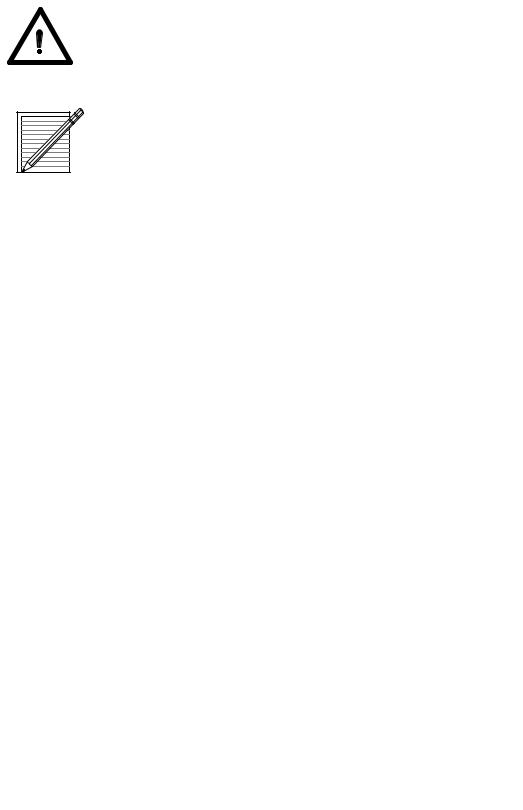
Attentions and useful notes are included in this manual to emphasize important and critical instructions. They are accompanied by a special symbol in the margin of the page and are printed in italics.
ATTENTION
All special problems, warnings or important text will be accompanied by this symbol at the appropriate position.
NOTE
Text associated with this symbol provides the user with useful notes. Carefully read the text as it is important for understanding the specific topic/command.
1.1.2.2.2Updating the Service Manual
As the instrument or parts of the instrument are constantly being improved, this Service Manual will regularly be updated. Each Service Technician will be sent update-sets and is responsible that his Service Manual is kept up to date. Necessary instructions of how to do this will be included in the update-set.
It is most important that your Service Manual is kept up to date. On receipt of an Update, carefully follow the instructions on the cover page and then file the cover page after this section.
1.1.2.2.3Service Bulletins
Service Bulletins are sent to immediately inform the Service Technician. File the Bulletins in this section to keep the Manual up to date.
1.1.2.2.4Service Part Classifications
Spare Part |
Description |
|
Class (SPC) |
||
|
||
|
|
|
I |
Instrument |
|
|
|
|
A |
Service Technician always has these parts with him |
|
|
|
|
B |
Dealer has part in stock |
|
|
|
|
C |
Hamilton has part in stock |
|
|
|
|
P |
Promotion Material |
|
|
|
|
T |
Service Tools |
|
|
|
|
V |
Consumables |
|
|
|
|
Z |
Accessories |
|
|
|
|
|
Not a Spare Part |
|
|
|
1-5

———ML F.A.M.E. Service Manual V2.0 ———————————————————————————————————————————— SYSTEM ———
1.1.2.2.5Service Assemblies
Parts labelled with part numbers rather than item numbers on the 3D drawings are Service Assemblies and should not be disassembled by the Service Technician. If a part of the assembly is defective, the whole assembly must be replaced.
1.1.2.2.6ML F.A.M.E. instruments with CE conformity
Instruments with serial numbers greater than 2000 are CE conform. Below is a table listing which board revisions may be installed into CE conform instruments.
Description |
Part Number |
New Revisions |
|
CE Conform |
|||
|
|
||
|
|
|
|
Motherboard E PCB |
146 164 |
01 |
|
|
|
|
|
Motherboard W/D PCB |
146 168 |
01 |
|
|
|
|
|
Motherboard P PCB |
146 170 |
01 |
|
|
|
|
|
Incubator PCB |
146 178 |
03 |
|
|
|
|
|
Entry PCB |
146 176 |
03 |
|
|
|
|
|
Exit PCB |
146 186 |
03 |
|
|
|
|
|
Power Supply 2 PCB |
146 172 |
04 |
|
|
|
|
|
Power Supply 1 PCB |
146 284 |
04 |
|
|
|
|
|
External Pump Station PCB |
146 240 |
02 |
|
|
|
|
ATTENTION
The following boards (including those with a lower revision) must not be used in CE-conform instruments: Incubator PCB 146178/02, Exit PCB 146186/02, Power Supply 2 PCB 146172/03, and External Pump Station PCB 146240/01.
1-6
———ML F.A.M.E. Service Manual V2.0 ————————————————————————————————————————————— SYSTEM ———
1.1.2.2.7Pin coding for PCBs
|
• = Pin fitted |
|
|
|
|
|
|
|
|
|
|
|
|
|
|
|
|
|
|
|||||||
Type: Codes for Processor Boards: |
|
Codes for Motherboards: |
||||||||||||||||||||||||
|
|
|
|
|
|
|
|
|
|
|
|
|
|
|
|
|
|
|
|
|
|
|
|
|
|
|
|
A |
B |
C |
D |
E |
F |
G |
H |
I |
K |
L |
M |
|
A |
B |
C |
D |
E |
F |
G |
H |
I |
K |
L |
M |
|
|
|
|
|
|
|
|
|
|
|
|
|
|
• |
|
|
|
|
|
|
|
|
|
|
|
|
|
|
|
|
|
|
|
|
|
|
|
|
|
|
|
|
|
|
|
|
|
|
|
|
|
|
|
|
UP 1 |
• |
|
• |
• |
• |
• |
|
|
|
|
|
|
• |
|
|
|
|
|
|
• |
• |
• |
• |
|||
|
|
|
|
|
|
|
|
|
|
|
|
• |
|
|
|
|
|
|
|
|
|
|
|
|||
UP 2 |
• |
|
• |
• |
• |
|
• |
|
|
|
|
|
• |
|
|
|
• |
|
• • |
• |
• |
|||||
|
|
|
|
|
|
|
|
|
|
|
|
• |
|
|
|
|
|
|
|
|
|
|
||||
UP 3 |
• |
|
• |
• |
• |
|
|
• |
|
|
|
|
• |
|
|
|
• |
• • |
• |
• |
||||||
|
|
|
|
|
|
|
|
|
|
|
|
• |
|
|
|
|
|
|
|
|
|
|
|
|
||
UP 4 |
• |
|
• |
• |
• |
|
|
|
• |
|
|
|
• |
|
|
|
• |
• |
|
|
|
• |
• |
|||
Codes for Peripheral Boards:
|
A |
B |
C |
D |
E |
F |
G |
H |
I |
K |
L |
M |
|
A |
B |
C |
D |
E |
F |
G |
H |
I |
K |
L |
M |
|
|
|
|
|
|
|
|
|
|
|
|
|
|
|
|
|
|
|
|
|
|
|
|
|
|
|
|
• |
|
|
|
|
|
|
|
|
|
|
|
|
|
|
|
|
|
|
|
|
|
|
|
|
|
|
|
||
Power Supply 1 PCB |
|
• |
• |
• |
|
|
|
|
• |
• |
• |
|
• |
|
|
|
|
• |
• |
• |
|
|
|
||||
|
|
|
|
|
|
|
|
|
|
|
|
|
|
|
|
|
|
|
|
|
|
|
|
|
• |
||
Power Supply 2 PCB |
|
• |
• |
|
• |
|
|
|
• |
• |
• |
|
• |
|
|
• |
|
• • |
• |
|
|
|
|||||
|
|
|
|
|
|
|
|
|
|
|
|
|
|
|
|
|
|
|
|
|
|
|
• |
||||
Entry |
|
• |
• |
• |
|
|
• |
|
• |
• |
|
• |
|
|
|
• |
• |
|
|
• |
|
|
|||||
|
|
|
|
|
|
|
|
|
|
|
|
|
|
|
|
|
|
|
|
|
|
|
• |
||||
Incubator |
|
• |
• |
• • |
|
• |
|
|
|
• |
|
• |
|
|
|
|
• |
• |
• |
• |
|
||||||
|
|
|
|
|
|
|
|
|
|
|
|
|
|
|
|
|
|
|
|
|
|
|
• |
||||
Step Motor |
|
• |
• |
• • |
|
|
• |
|
|
• |
|
• |
|
|
|
|
• • |
|
|
• |
• |
|
|||||
|
|
|
|
|
|
|
|
|
|
|
|
|
|
|
|
|
|
|
|
|
• |
||||||
Dispenser |
|
• |
• |
• • |
|
|
|
• |
|
• |
|
• |
|
|
|
|
• • • |
|
• |
|
|||||||
|
|
|
|
|
|
|
|
|
|
|
|
|
|
|
|
|
|
|
|
|
• |
||||||
Washer |
|
• |
• |
• • |
|
|
|
|
• |
• |
|
• |
|
|
|
|
• • • |
• |
|
|
|||||||
|
|
|
|
|
|
|
|
|
|
|
|
|
|
|
|
|
|
|
|
|
|
• |
|||||
Exit |
|
• |
• |
• |
|
• |
|
|
• |
• |
|
• |
|
|
|
• |
• |
• |
• |
|
|
||||||
1.1.2.2.8Connector numbering
The drawing on the following page 614 149 illustrates the connector numbering system used for ML F.A.M.E.
1-7
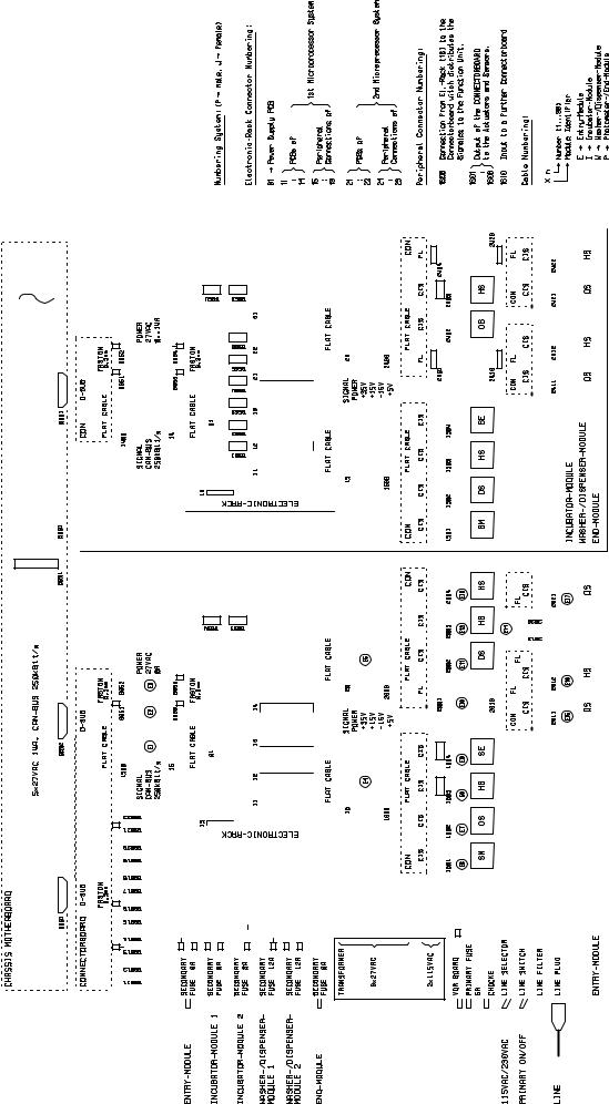
——— ML F.A.M.E. Service Manual V2.0 ———————————————————————————————————————————— SYSTEM ———
|
|
|
Wiring Principle Block Diagram 614 149 |
|
|
|
|
|
|
|
revision 00 |
|
|
|
|
|
|
|
|
|
|
|
|||||||||||||||||||||||||||||||||||||||||||||||||||||||||||||||||||||||||||||||||||||||||||||||||||||||||||||||||||||||||||
|
|
|
|
|
|
|
|
|
|
|
|
|
|
|
|
|
|
|
|
|
|
|
|
|
|
|
|
|
|
|
|
|
|
|
|
|
|
|
|
|
|
|
|
|
|
|
|
|
|
|
|
|
|
|
|
|
|
|
|
|
|
|
|
|
|
|
|
|
|
|
|
|
|
|
|
|
|
|
|
|
|
|
|
|
|
|
|
|
|
|
|
|
|
|
|
|
|
|
|
|
|
|
|
|
|
|
|
|
|
|
|
|
|
|
|
|
|
|
|
|
|
|
|
|
|
|
|
|
|
|
|
|
|
|
|
|
|
|
|
|
|
|
|
|
|
|
|
|
|
|
|
|
|
|
|
|
|
|
|
|
|
|
|
|
|
|
|
|
|
|
|
|
|
|
|
|
|
|
|
|
|
|
|
|
|
|
|
|
|
|
|
|
|
|
|
|
|
|
|
|
|
|
|
|
|
|
|
|
|
|
|
|
|
|
|
|
|
|
|
|
|
|
|
|
|
|
|
|
|
|
|
|
|
|
|
|
|
|
|
|
|
|
|
|
|
|
|
|
|
|
|
|
|
|
|
|
|
|
|
|
|
|
|
|
|
|
|
|
|
|
|
|
|
|
|
|
|
|
|
|
|
|
|
|
|
|
|
|
|
|
|
|
|
|
|
|
|
|
|
|
|
|
|
|
|
|
|
|
|
|
|
|
|
|
|
|
|
|
|
|
|
|
|
|
|
|
|
|
|
|
|
|
|
|
|
|
|
|
|
|
|
|
|
|
|
|
|
|
|
|
|
|
|
|
|
|
|
|
|
|
|
|
|
|
|
|
|
|
|
|
|
|
|
|
|
|
|
|
|
|
|
|
|
|
|
|
|
|
|
|
|
|
|
|
|
|
|
|
|
|
|
|
|
|
|
|
|
|
|
|
|
|
|
|
|
|
|
|
|
|
|
|
|
|
|
|
|
|
|
|
|
|
|
|
|
|
|
|
|
|
|
|
|
|
|
|
|
|
|
|
|
|
|
|
|
|
|
|
|
|
|
|
|
|
|
|
|
|
|
|
|
|
|
|
|
|
|
|
|
|
|
|
|
|
|
|
|
|
|
|
|
|
|
|
|
|
|
|
|
|
|
|
|
|
|
|
|
|
|
|
|
|
|
|
|
|
|
|
|
|
|
|
|
|
|
|
|
|
|
|
|
|
|
|
|
|
|
|
|
|
|
|
|
|
|
|
|
|
|
|
|
|
|
|
|
|
|
|
|
|
|
|
|
|
|
|
|
|
|
|
|
|
|
|
|
|
|
|
|
|
|
|
|
|
|
|
|
|
|
|
|
|
|
|
|
|
|
|
|
|
|
|
|
|
|
|
|
|
|
|
|
|
|
|
|
|
|
|
|
|
|
|
|
|
|
|
|
|
|
|
|
|
|
|
|
|
|
|
|
|
|
|
|
|
|
|
|
|
|
|
|
|
|
|
|
|
|
|
|
|
|
|
|
|
|
|
|
|
|
|
|
|
|
|
|
|
|
|
|
|
|
|
|
|
|
|
|
|
|
|
|
|
|
|
|
|
|
|
|
|
|
|
|
|
|
|
|
|
|
|
|
|
|
|
|
|
|
|
|
|
|
|
|
|
|
|
|
|
|
|
|
|
|
|
|
|
|
|
|
|
|
|
|
|
|
|
|
|
|
|
|
|
|
|
|
|
|
|
|
|
|
|
|
|
|
|
|
|
|
|
|
|
|
|
|
|
|
|
|
|
|
|
|
|
|
|
|
|
|
|
|
|
|
|
|
|
|
|
|
|
|
|
|
|
|
|
|
|
|
|
|
|
|
|
|
|
|
|
|
|
|
|
|
|
|
|
|
|
|
|
|
|
|
|
|
|
|
|
|
|
|
|
|
|
|
|
|
|
|
|
|
|
|
|
|
|
|
|
|
|
|
|
|
|
|
|
|
|
|
|
|
|
|
|
|
|
|
|
|
|
|
|
|
|
|
|
|
|
|
|
|
|
|
|
|
|
|
|
|
|
|
|
|
|
|
|
|
|
|
|
|
|
|
|
|
|
|
|
|
|
|
|
|
|
|
|
|
|
|
|
|
|
|
|
|
|
|
|
|
|
|
|
|
|
|
|
|
|
|
|
|
|
|
|
|
|
|
|
|
|
|
|
|
|
|
|
|
|
|
|
|
|
|
|
|
|
|
|
|
|
|
|
|
|
|
|
|
|
|
|
|
|
|
|
|
|
|
|
|
|
|
|
|
|
|
|
|
|
|
|
|
|
|
|
|
|
|
|
|
|
|
|
|
|
|
|
|
|
|
|
|
|
|
|
|
|
|
|
|
|
|
|
|
|
|
|
|
|
|
|
|
|
|
|
|
|
|
|
|
|
|
|
|
|
|
|
|
|
|
|
|
|
|
|
|
|
|
|
|
|
|
|
|
|
|
|
|
|
|
|
|
|
|
|
|
|
|
|
|
|
|
|
|
|
|
|
|
|
|
|
|
|
|
|
|
|
|
|
|
|
|
|
|
|
|
|
|
|
|
|
|
|
|
|
|
|
|
|
|
|
|
|
|
|
|
|
|
|
|
|
|
|
|
|
|
|
|
|
|
|
|
|
|
|
|
|
|
|
|
|
|
|
|
|
|
|
|
|
|
|
|
|
|
|
|
|
|
|
|
|
|
|
|
|
|
|
|
|
|
|
|
|
|
|
|
|
|
|
|
|
|
|
|
|
|
|
|
|
|
|
|
|
|
|
|
|
|
|
|
|
|
|
|
|
|
|
|
|
|
|
|
|
|
|
|
|
|
|
|
|
|
|
|
|
|
|
|
|
|
|
|
|
|
|
|
|
|
|
|
|
|
|
|
|
|
|
|
|
|
|
|
|
|
|
|
|
|
|
|
|
|
|
|
|
|
|
|
|
|
|
|
|
|
|
|
|
|
|
|
|
|
|
|
|
|
|
|
|
|
|
|
|
|
|
|
|
|
|
|
|
|
|
|
|
|
|
|
|
|
|
|
|
|
|
|
|
|
|
|
|
|
|
|
|
|
|
|
|
|
|
|
|
|
|
|
|
|
|
|
|
|
|
|
|
|
|
|
|
|
|
|
|
|
|
|
|
|
|
|
|
|
|
|
|
|
|
|
|
|
|
|
|
|
|
|
|
|
|
|
|
|
|
|
|
|
|
|
|
|
|
|
|
|
|
|
|
|
|
|
|
|
|
|
|
|
|
|
|
|
|
|
|
|
|
|
|
|
|
|
|
|
|
|
|
|
|
|
|
|
|
|
|
|
|
|
|
|
|
|
|
|
|
|
|
|
|
|
|
|
|
|
|
|
|
|
|
|
|
|
|
|
|
|
|
|
|
|
|
|
|
|
|
|
|
|
|
|
|
|
|
|
|
|
|
|
|
|
|
|
|
|
|
|
|
|
|
|
|
|
|
|
|
|
|
|
|
|
|
|
|
|
|
|
|
|
|
|
|
|
|
|
|
|
|
|
|
|
|
|
|
|
|
|
|
|
|
|
|
|
|
|
|
|
|
|
|
|
|
|
|
|
|
|
|
|
|
|
|
|
|
|
|
|
|
|
|
|
|
|
|
|
|
|
|
|
|
|
|
|
|
|
|
|
|
|
|
|
|
|
|
|
|
|
|
|
|
|
|
|
|
|
|
|
|
|
|
|
|
|
|
|
|
|
|
|
|
|
|
|
|
|
|
|
|
|
|
|
|
|
|
|
|
|
|
|
|
|
|
|
|
|
|
|
|
|
|
|
|
|
|
|
|
|
|
|
|
|
|
|
|
|
|
|
|
|
|
|
|
|
|
|
|
|
|
|
|
|
|
|
|
|
|
|
|
|
|
|
|
|
|
|
|
|
|
|
|
|
|
|
|
|
|
|
|
|
|
|
|
|
|
|
|
|
|
|
|
|
|
|
|
|
|
|
|
|
|
|
|
|
|
|
|
|
|
|
|
|
|
|
|
|
|
|
|
|
|
|
|
|
|
|
|
|
|
|
|
|
|
|
|
|
|
|
|
|
|
|
|
|
|
|
|
|
|
|
|
|
|
|
|
|
|
|
|
|
|
|
|
|
|
|
|
|
|
|
|
|
|
|
|
|
|
|
|
|
|
|
|
|
|
|
|
|
|
|
|
|
|
|
|
|
|
|
|
|
|
|
|
|
|
|
|
|
|
|
|
|
|
|
|
|
|
|
|
|
|
|
|
|
|
|
|
|
|
|
|
|
|
|
|
|
|
|
|
|
|
|
|
|
|
|
|
|
|
|
|
|
|
|
|
|
|
|
|
|
|
|
|
|
|
|
|
|
|
|
|
|
|
|
|
|
|
|
|
|
|
|
|
|
|
|
|
|
|
|
|
|
|
|
|
|
|
|
|
|
|
|
|
|
|
|
|
|
|
|
|
|
|
|
|
|
|
|
|
|
|
|
|
|
|
|
|
|
|
|
|
|
|
|
|
|
|
|
|
|
|
|
|
|
|
|
|
|
|
|
|
|
|
|
|
|
|
|
|
|
|
|
|
|
|
|
|
|
|
|
|
|
|
|
|
|
|
|
|
|
|
|
|
|
|
|
|
|
|
|
|
|
|
|
|
|
|
|
|
|
|
|
|
|
|
|
|
|
|
|
|
|
|
|
|
|
|
|
|
|
|
|
|
|
|
|
|
|
|
|
|
|
|
|
|
|
|
|
|
|
|
|
|
|
|
|
|
|
|
|
|
|
|
|
|
|
|
|
|
|
|
|
|
|
|
|
|
|
|
|
|
|
|
|
|
|
|
|
|
|
|
|
|
|
|
|
|
|
|
|
|
|
|
|
|
|
|
|
|
|
|
|
|
|
|
|
|
|
|
|
|
|
|
|
|
|
|
|
|
|
|
|
|
|
|
|
|
|
|
|
|
|
|
|
|
|
|
|
|
|
|
|
|
|
|
|
|
|
|
|
|
|
|
|
|
|
|
|
|
|
|
|
|
|
|
|
|
|
|
|
|
|
|
|
|
|
|
|
|
|
|
|
|
|
|
|
|
|
|
|
|
|
|
|
|
|
|
|
|
|
|
|
|
|
|
|
|
|
|
|
|
|
|
|
|
|
|
|
|
|
|
|
|
|
|
|
|
|
|
|
|
|
|
|
|
|
|
|
|
|
|
|
|
|
|
|
|
|
|
|
|
|
|
|
|
|
|
|
|
|
|
|
|
|
|
|
|
|
|
|
|
|
|
|
|
|
|
|
|
|
|
|
|
|
|
|
|
|
|
|
|
|
|
|
|
|
|
|
|
|
|
|
|
|
|
|
|
|
|
|
|
|
|
|
|
|
|
|
|
|
|
|
|
|
|
|
|
|
|
|
|
|
|
|
|
|
|
|
|
|
|
|
|
|
|
|
|
|
|
|
|
|
|
|
|
|
|
|
|
|
|
|
|
|
|
|
|
|
|
|
|
|
|
|
|
|
|
|
|
|
|
|
|
|
|
|
|
|
|
|
|
|
|
|
|
|
|
|
|
|
|
|
|
|
|
|
|
|
|
|
|
|
|
|
|
|
|
|
|
|
|
|
|
|
|
|
|
|
|
|
|
|
|
|
|
|
|
|
|
|
|
|
|
|
|
|
|
|
|
|
|
|
|
|
|
|
|
|
|
|
|
|
|
|
|
|
|
|
|
|
|
|
|
|
|
|
|
|
|
|
|
|
|
|
|
|
|
|
|
|
|
|
|
|
|
|
|
|
|
|
|
|
|
|
|
|
|
|
|
|
|
|
|
|
|
|
|
|
|
|
|
|
|
|
|
|
|
|
|
|
|
|
|
|
|
|
|
|
|
|
|
|
|
|
|
|
|
|
|
|
|
|
|
|
|
|
|
|
|
|
|
|
|
|
|
|
|
|
|
|
|
|
|
|
|
|
|
|
|
|
|
|
|
|
|
|
|
|
|
|
|
|
|
|
|
|
|
|
|
|
|
|
|
|
|
|
|
|
|
|
|
|
|
|
|
|
|
|
|
|
|
|
|
|
|
|
|
|
|
|
|
|
|
|
|
|
|
|
|
|
|
|
|
|
|
|
|
|
|
|
|
|
|
|
|
|
|
|
|
|
|
|
|
|
|
|
|
|
|
|
|
|
|
|
|
|
|
|
|
|
|
|
|
|
|
|
|
|
|
|
|
|
|
|
|
|
|
|
|
|
|
|
|
|
|
|
|
|
|
|
|
|
|
|
|
|
|
|
|
|
|
|
|
|
|
|
|
|
|
|
|
|
|
|
|
|
|
|
|
|
|
|
|
|
|
|
|
|
|
|
|
|
|
|
|
|
|
|
|
|
|
|
|
|
|
|
|
|
|
|
|
|
|
|
|
|
|
|
|
|
|
|
|
|
|
|
|
|
|
|
|
|
|
|
|
|
|
|
|
|
|
|
|
|
|
|
|
|
|
|
|
|
|
|
|
|
|
|
|
|
|
|
|
|
|
|
|
|
|
|
|
|
|
|
|
|
|
|
|
|
|
|
|
|
|
|
|
|
|
|
|
|
|
|
|
|
|
|
|
|
|
|
|
|
|
|
|
|
|
|
|
|
|
|
|
|
|
|
|
|
|
|
|
|
|
|
|
|
|
|
|
|
|
|
|
|
|
|
|
|
|
|
|
|
|
|
|
|
|
|
|
|
|
|
|
|
|
|
|
|
|
|
|
|
|
|
|
|
|
|
|
|
|
|
|
|
|
|
|
|
|
|
|
|
|
|
|
|
|
|
|
|
|
|
|
|
|
|
|
|
|
|
|
|
|
|
|
|
|
|
|
|
|
|
|
|
|
|
|
|
|
|
|
|
|
|
|
|
|
|
|
|
|
|
|
|
|
|
|
|
|
|
|
|
|
|
|
|
|
|
|
|
|
|
|
|
|
|
|
|
|
|
|
|
|
|
|
|
|
|
|
|
|
|
|
|
|
|
|
|
|
|
|
|
|
|
|
|
|
|
|
|
|
|
|
|
|
|
|
|
|
|
|
|
|
|
|
|
|
|
|
|
|
|
|
|
|
|
|
|
|
|
|
|
|
|
|
|
|
|
|
|
|
|
|
|
|
|
|
|
|
|
|
|
|
|
|
|
|
|
|
|
|
|
|
|
|
|
|
|
|
|
|
|
|
|
|
|
|
|
|
|
|
|
|
|
|
|
|
|
|
|
|
|
|
|
|
|
|
|
|
|
|
|
|
|
|
|
|
|
|
|
|
|
|
|
|
|
|
|
|
|
|
|
|
|
|
|
|
|
|
|
|
|
|
|
|
|
|
|
|
|
|
|
|
|
|
|
|
|
|
|
|
|
|
|
|
|
|
|
|
|
|
|
|
|
|
|
|
|
|
|
|
|
|
|
|
|
|
|
|
|
|
|
|
|
|
|
|
|
|
|
|
|
|
|
|
|
|
|
|
|
|
|
|
|
|
|
|
|
|
|
|
|
|
|
|
|
|
|
|
|
|
|
|
|
|
|
|
|
|
|
|
|
|
|
|
|
|
|
|
|
|
|
|
|
|
|
|
|
|
|
|
|
|
|
|
|
|
|
|
|
|
|
|
|
|
|
|
|
|
|
|
|
|
|
|
|
|
|
|
|
|
|
|
|
|
|
|
|
|
|
|
|
|
|
|
|
|
|
|
|
|
|
|
|
|
|
|
|
|
|
|
|
|
|
|
|
|
|
|
|
|
|
|
|
|
|
|
|
|
|
|
|
|
|
|
|
|
|
|
|
|
|
|
|
|
|
|
|
|
|
|
|
|
|
|
|
|
|
|
|
|
|
|
|
|
|
|
|
|
|
|
|
|
|
|
|
|
|
|
|
|
|
|
|
|
|
|
|
|
|
|
|
|
|
|
|
|
|
|
|
|
|
|
|
|
|
|
|
|
|
|
|
|
|
|
|
|
|
|
|
|
|
|
|
|
|
|
|
|
|
|
|
|
|
|
|
|
|
|
|
|
|
|
|
|
|
|
|
|
|
|
|
|
|
|
|
|
|
|
|
|
|
|
|
|
|
|
|
|
|
|
|
|
|
|
|
|
|
|
|
|
|
|
|
|
|
|
|
|
|
|
|
|
|
|
|
|
|
|
|
|
|
|
|
|
|
|
|
|
|
|
|
|
|
|
|
|
|
|
|
|
|
|
|
|
|
|
|
|
|
|
|
|
|
|
|
|
|
|
|
|
|
1-8
——— ML F.A.M.E. Service Manual V2.0 ————————————————————————————————————————————— SYSTEM ———
1.1.2.3Feedback (Quarterly Service Call Statistics)
Information from the field is a determining factor for improving Hamilton products. Please send/fax a copy of all of your Service Reports to Hamilton Bonaduz AG every three months so that we may continue to provide quality products and services.
1.1.2.4Parts Return Tag
The part Return Tag has two functions:
Page 1: Part identification, reason for return and description of problem
Page 2: Decontamination Declaration
Material Return Good Authorization
Parts or instruments may only be returned to Hamilton Bonaduz AG with a Return Good Authorization (RGA).
Ask the Hamilton Order Processing Department (OPD) for an RGA number prior to sending any material. This number must be entered in the appropriate blank on the Parts Return Tag.
A completed Part Return Tag must be attached to all parts or instruments which are returned to HAMILTON BONADUZ AG. Tags may be ordered from Hamilton Bonaduz AG (p/n 612 554).
Hamilton Bonaduz AG reserves the right to return any parts or instruments which may pose a health hazard due to contamination and to charge the customer for any expenses incurred.
1.1.2.5Technical Data Sheet
The technical data sheet is supplied with each instrument and contains all technical data of a specific instrument. It must be updated by the service technician when significant modifications are made.
1-9

——— ML F.A.M.E. Service Manual V2.0 ———————————————————————————————————————————— SYSTEM ———
1.1.2.6Service Kit
1.1.2.6.1Service Kit Spare Parts List 148 236
SPARE CASE ML F.A.M.E. REV: 00
P/N |
DESCRIPTION |
REVISION |
ITEM |
QUANTITY PER |
SPARE PART |
|
NUMBER |
ASSEMBLY |
CLASS |
||||
|
|
|
||||
|
|
|
|
|
|
|
141239 |
KLEMMRING |
01 |
1 |
1.000 |
A |
|
|
|
|
|
|
|
|
146154 |
CONNECTORBOARD E1 PCB |
00 |
2 |
1.000 |
A |
|
146156 |
CONNECTORBOARD I1 PCB |
00 |
3 |
1.000 |
A |
|
|
|
|
|
|
|
|
146158 |
CONNECTORBOARD P1 PCB |
00 |
4 |
1.000 |
A |
|
146172 |
POWER SUPPLY 2 PCB |
04 |
7 |
1.000 |
A |
|
|
|
|
|
|
|
|
146174 |
STEP MOTOR PCB |
00 |
8 |
1.000 |
A |
|
146178 |
INKUBATOR PCB |
02 |
9 |
1.000 |
A |
|
|
|
|
|
|
|
|
146180 |
DISPENSER PCB |
01 |
10 |
1.000 |
A |
|
146182 |
WASHER PCB |
02 |
11 |
1.000 |
A |
|
|
|
|
|
|
|
|
146186 |
EXIT PCB |
03 |
12 |
1.000 |
A |
|
146188 |
IC27C256 PRO VEDLS10.ACH |
00 |
13 |
1.000 |
A |
|
|
|
|
|
|
|
|
146195 |
CONNECTORBOARD W1 PCB |
02 |
14 |
1.000 |
A |
|
146197 |
CONNECTORBOARD W2 PCB |
02 |
15 |
1.000 |
A |
|
|
|
|
|
|
|
|
146201 |
CONNECTORBOARD W4 PCB |
00 |
16 |
1.000 |
A |
|
146407 |
CONNECTORBOARD W5 PCB |
00 |
17 |
1.000 |
A |
|
|
|
|
|
|
|
|
146209 |
CONNECTORBOARD W8 PCB |
00 |
19 |
1.000 |
A |
|
146411 |
CABLE W7 |
00 |
20 |
1.000 |
A |
|
|
|
|
|
|
|
|
146218 |
CABLE W8 |
00 |
21 |
1.000 |
A |
|
146222 |
CABLE W12 |
00 |
22 |
1.000 |
A |
|
|
|
|
|
|
|
|
146230 |
CONNECTORBOARD W11 PCB |
00 |
23 |
1.000 |
A |
|
146232 |
CONNECTORBOARD W12 PCB |
00 |
24 |
1.000 |
A |
|
|
|
|
|
|
|
|
146234 |
CONNECTORBOARD W13 PCB |
00 |
25 |
1.000 |
A |
|
146236 |
CONNECTORBOARD W14 PCB |
00 |
26 |
1.000 |
A |
|
|
|
|
|
|
|
|
146240 |
EXTERNAL PUMP STATION PCB |
02 |
27 |
1.000 |
A |
|
146243 |
PHOTOMETER PROCESSOR PCB |
00 |
29 |
1.000 |
A |
|
|
|
|
|
|
|
|
146244 |
CONNECTORBOARD P20 PCB |
00 |
30 |
1.000 |
A |
|
146245 |
LAMP CONTROLLER PCB |
00 |
31 |
1.000 |
A |
|
|
|
|
|
|
|
|
146256 |
CONNECTORBOARD W9 PCB |
01 |
32 |
1.000 |
A |
|
146257 |
CONNECTORBOARD E8 PCB |
00 |
33 |
1.000 |
A |
|
|
|
|
|
|
|
|
146259 |
CONNECTORBOARD P2 PCB |
00 |
34 |
1.000 |
A |
|
146261 |
CONNECTORBOARD P3 PCB |
00 |
35 |
1.000 |
A |
|
|
|
|
|
|
|
|
146263 |
CONNECTORBOARD P4 PCB |
00 |
36 |
1.000 |
A |
|
146265 |
CONNECTORBOARD P5 PCB |
00 |
37 |
1.000 |
A |
|
|
|
|
|
|
|
|
146266 |
CONNECTORBOARD P6 PCB |
00 |
38 |
1.000 |
A |
|
146268 |
CONNECTORBOARD P9 PCB |
00 |
39 |
1.000 |
A |
|
|
|
|
|
|
|
|
146271 |
CONNECTORBOARD P8 PCB |
00 |
40 |
1.000 |
A |
|
146275 |
LAMP-ASSEMBLY PCB |
00 |
41 |
1.000 |
A |
|
|
|
|
|
|
|
|
146278 |
CONNECTORBOARD W16 PCB |
01 |
42 |
1.000 |
A |
|
146298 |
CABLE W44 |
00 |
43 |
1.000 |
A |
|
|
|
|
|
|
|
|
146308 |
TEMPERATURE SENSOR TS70 |
00 |
44 |
1.000 |
A |
|
146311 |
CONNECTORBOARD E6 PCB |
00 |
45 |
1.000 |
A |
|
|
|
|
|
|
|
|
146312 |
CONNECTORBOARD E7 PCB |
00 |
46 |
1.000 |
A |
|
146313 |
CONNECTORBOARD E9 PCB |
00 |
47 |
1.000 |
A |
|
|
|
|
|
|
|
1-10

——— ML F.A.M.E. Service Manual V2.0 ————————————————————————————————————————————— SYSTEM ———
P/N |
DESCRIPTION |
REVISION |
ITEM |
QUANTITY PER |
SPARE PART |
|
NUMBER |
ASSEMBLY |
CLASS |
||||
|
|
|
||||
|
|
|
|
|
|
|
146314 |
CONNECTORBOARD E10 PCB |
00 |
48 |
1.000 |
A |
|
146322 |
CONNECTORBOARD E11 PCB |
00 |
49 |
1.000 |
A |
|
|
|
|
|
|
|
|
146352 |
CABLE E20 |
00 |
50 |
1.000 |
A |
|
146384 |
A/D CONVERTER PCB |
00 |
53 |
1.000 |
A |
|
|
|
|
|
|
|
|
146386 |
CONNECTORBOARD E14 PCB |
00 |
54 |
1.000 |
A |
|
146388 |
CONNECTORBOARD E12 PCB |
00 |
55 |
1.000 |
A |
|
|
|
|
|
|
|
|
146390 |
CONNECTORBOARD E13 PCB |
00 |
56 |
1.000 |
A |
|
147417 |
ISOLIERSCHEIBE |
00 |
58 |
1.000 |
A |
|
|
|
|
|
|
|
|
147489 |
SCHWIMMER |
01 |
59 |
1.000 |
A |
|
147638 |
KABELKLEMME |
00 |
61 |
1.000 |
A |
|
|
|
|
|
|
|
|
147683 |
FILTERMATTE |
00 |
62 |
1.000 |
A |
|
147693 |
VERBINDUNGSSTUECK NW 8/45? |
00 |
63 |
1.000 |
A |
|
|
|
|
|
|
|
|
147720 |
SHELL-FEDER |
00 |
64 |
1.000 |
A |
|
147777 |
ABDECKFOLIE |
00 |
65 |
1.000 |
A |
|
|
|
|
|
|
|
|
147935 |
MTP-TRANSPORTER |
00 |
66 |
1.000 |
Z |
|
148157 |
KONTAKTFEDER |
00 |
67 |
1.000 |
A |
|
|
|
|
|
|
|
|
148228 |
MODULE TRANSPORT FORK COMPL. |
01 |
68 |
1.000 |
A |
|
148230 |
REGULATING SCREW 1 COMPL. |
00 |
69 |
1.000 |
A |
|
|
|
|
|
|
|
|
148231 |
REGULATING SCREW 2 COMPL. |
00 |
70 |
1.000 |
A |
|
249944 |
SCHLAUCHVERBINDER 6/10/6 |
00 |
71 |
1.000 |
A |
|
|
|
|
|
|
|
|
254101 |
O-RING 85.32x3.53 VITON 75 |
00 |
72 |
1.000 |
A |
|
254106 |
O-RING 12.00X2.00 VITON |
00 |
73 |
1.000 |
A |
|
|
|
|
|
|
|
|
254110 |
O-RING 76.00X2.00 VITON |
00 |
74 |
1.000 |
A |
|
254111 |
O-RING 5.00X1.50 VITON |
00 |
75 |
1.000 |
A |
|
|
|
|
|
|
|
|
254121 |
O-RING 79X2 NBR 70.5/P5 |
00 |
76 |
1.000 |
A |
|
256115 |
ZUGFED. D 0,32 DA 3,52 LO 12,9 |
00 |
77 |
1.000 |
A |
|
|
|
|
|
|
|
|
256116 |
ZUGFEDER D 0.50 DM 3.0 LO 24.5 |
00 |
78 |
1.000 |
A |
|
257036 |
DISTANZHALTER M3 X 8 I/I GEW. |
00 |
79 |
1.000 |
A |
|
|
|
|
|
|
|
|
257040 |
DIST.HALTER M4X20 I/A GEW. |
00 |
80 |
1.000 |
A |
|
257041 |
DIST.HALTER M4X 25 I/A GEW. |
00 |
81 |
1.000 |
A |
|
|
|
|
|
|
|
|
279448 |
SCHWINGUNGSDAEMPFER D=15 H=20 |
|
83 |
1.000 |
A |
|
279648 |
WINKELSTUECK 90? PP ID 4-5 |
00 |
84 |
1.000 |
A |
|
|
|
|
|
|
|
|
279649 |
WINKELSTUECK 90? PP ID 8-9 |
00 |
85 |
1.000 |
A |
|
361019 |
KABELBEF. SES-CT |
00 |
86 |
3.000 |
|
|
|
|
|
|
|
|
|
422002 |
SPREIZNIETE KST D=5 KB=3.5-4.5 |
00 |
90 |
1.000 |
A |
|
420214 |
PT-SENKKOPFSCHRAUBE KA 30 X 8 |
00 |
91 |
2.000 |
A |
|
|
|
|
|
|
|
|
7279355 |
KLEBBAND 1-SEITIG D= 2 B= 6 |
00 |
92 |
0.200 |
|
|
147963 |
PHOTOMETER AIR FILTER |
00 |
93 |
1.000 |
A |
|
|
|
|
|
|
|
|
511006 |
LOCTITE 222 50mL |
00 |
94 |
1.000 |
T |
|
511010 |
LOCTITE 638 50mL |
00 |
96 |
1.000 |
T |
|
|
|
|
|
|
|
|
7249057 |
SILIKONSCHL 4 X 7 TRANSP |
00 |
97 |
1.000 |
B |
|
7260010 |
SILIKONSCHL 8 X12 TRANSP |
00 |
98 |
1.000 |
B |
|
|
|
|
|
|
|
|
148248 |
KLETTVERSCHLUSS |
00 |
99 |
4.000 |
A |
|
7281149 |
PTFE-KLEBEBAND EXTR.B=9MM |
00 |
100 |
0.200 |
|
|
|
|
|
|
|
|
|
7281122 |
KLEBBAND 2-SEITIG D=0,8 B=9 |
00 |
101 |
0.200 |
|
|
146328 |
TRANSPARENT COVER SENSOR HS03 |
00 |
102 |
1.000 |
A |
|
|
|
|
|
|
|
|
146416 |
REAGENT DRAWER SWITCH SET |
00 |
103 |
1.000 |
A |
|
254105 |
O-RING 8.00X2.00 VITON |
00 |
104 |
1.000 |
A |
|
|
|
|
|
|
|
|
254126 |
O-RING Di 5x2.5 VITON 75 |
00 |
105 |
1.000 |
A |
|
281110 |
STOPFEN D5.8 D7 L5 SILIKON |
00 |
106 |
1.000 |
A |
|
|
|
|
|
|
|
1-11

——— ML F.A.M.E. Service Manual V2.0 ———————————————————————————————————————————— SYSTEM ———
P/N |
DESCRIPTION |
REVISION |
ITEM |
QUANTITY PER |
SPARE PART |
|
NUMBER |
ASSEMBLY |
CLASS |
||||
|
|
|
||||
|
|
|
|
|
|
|
146405 |
IC27C256 PRO VEEPS11.ACH |
00 |
107 |
1.000 |
A |
|
235416 |
FARBFL. 7,5ML HELLBLAU HAM |
00 |
108 |
1.000 |
T |
|
|
|
|
|
|
|
|
235425 |
FARBFL. 7,5ML GRAUBLAU HAM |
00 |
109 |
1.000 |
T |
|
235418 |
HAERTERFLASCHE 7,5 ML |
00 |
110 |
1.000 |
T |
|
|
|
|
|
|
|
|
235417 |
FARBFL. 7,5ML DUNKELBLAU HAM |
00 |
111 |
1.000 |
T |
|
147581 |
JUSTIERSCHEIBE |
00 |
112 |
2.000 |
A |
|
|
|
|
|
|
|
|
369051 |
VERPACK CHIP CONTAINER TYP 2 |
00 |
114 |
1.000 |
|
|
511057 |
OEL MICROGLISS D-5 20ML |
00 |
115 |
1.000 |
T |
|
|
|
|
|
|
|
|
146394 |
CABLE MODULE CONNECTION |
00 |
116 |
2.000 |
T |
|
146395 |
SERVICE PCB |
00 |
117 |
1.000 |
T |
|
|
|
|
|
|
|
|
239038 |
ELEKTRONIKKOFFER |
00 |
118 |
2.000 |
|
|
239039 |
EINLEGEPLATTE |
00 |
119 |
8.000 |
|
|
|
|
|
|
|
|
|
148245 |
SETSCREW |
00 |
120 |
1.000 |
A |
|
147516 |
WASH FLUID LEVEL SENSOR |
00 |
121 |
1.000 |
A |
|
|
|
|
|
|
|
|
361036 |
KABELHALTER |
00 |
122 |
3.000 |
|
|
361002 |
KABELBEF. 375 S |
00 |
123 |
3.000 |
|
|
|
|
|
|
|
|
|
361004 |
KABELBEF. CFCC-4 1/2” |
00 |
124 |
3.000 |
|
|
369038 |
VERRIEGELUNGSMUTTER |
00 |
125 |
1.000 |
B |
|
|
|
|
|
|
|
|
255038 |
KENNZEICHNUNG LABEL 21X9 WEISS |
00 |
126 |
2.000 |
|
|
148339 |
SUPPORT ENTRY MODULE |
00 |
128 |
1.000 |
T |
|
|
|
|
|
|
|
|
148355 |
TRANSP COVER MAGNET |
00 |
129 |
1.000 |
T |
|
146409 |
CONNECTORBOARD W6 PCB |
00 |
130 |
1.000 |
A |
|
|
|
|
|
|
|
|
622054 |
PACKING LIST ML FAME |
05 |
131 |
1.000 |
|
|
511069 |
MOLYKOTE FETTPASTE DX |
00 |
132 |
1.000 |
T |
|
|
|
|
|
|
|
|
146317 |
PROCESSOR 4 PCB |
01 |
135 |
1.000 |
A |
|
235426 |
FARBFL.7,5ML SIGNALSCHW. |
00 |
136 |
1.000 |
T |
|
|
|
|
|
|
|
|
235427 |
FARBFL.7,5ML ACHATGRAU |
00 |
137 |
1.000 |
T |
|
|
|
|
|
|
|
1-12
——— ML F.A.M.E. Service Manual V2.0 ————————————————————————————————————————————— SYSTEM ———
1.1.2.6.2Service PCB (to be used with Diagnostic Master)
Component Layout 146.395 revision 00
1-13

——— ML F.A.M.E. Service Manual V2.0 ———————————————————————————————————————————— SYSTEM ———
|
|
|
|
|
Service PCB |
|
|
|
|
Wiring Diagram |
|
|
|
604.852 |
|
|
revision 00 |
|
|
|
|
|
|
|
|
|
|
|
|
|
|
|
|
|
|
|
|
|
|
|||||||||||||||||||||||||||||||||||||||||||||||||||||||||||
|
|
GND 5V |
GND 5V |
GND 5V +5VDC +5VDC +5VDC |
|
|
|
|
|
|
|
|
|
|
|
+35VDC on WA |
|
|
|
|
|
|
|
|
|
|
|
|
|
|
|
|
|
|
|
|
|
|
|
|
|
|
|
|
|
|
|
|
|
|
|
VACUUM PUMP on WA |
|
STEP MOTOR on SM / VACUUM PUMP on WA |
|
STEP MOTOR on SM, WA / +35VDC on IN |
|
STEP MOTOR on SM, WA /HEATING ELEMENT on IN |
|
STEP MOTOR on SM, DS, WA / HEATING ELEMENT on IN |
|
STEP MOTOR on SM, DS, WA, EX / HEATING ELEMENT on IN |
|
STEP MOTOR on SM, DS, EX / HEATING ELEMENT on IN |
|
STEP MOTOR on SM, DS, EX / HEATING ELEMENT on IN |
|
STEP MOTOR on SM, DS, EX / HEATING ELEMENT on IN |
|
STEP MOTOR on SM, ET, DS, EX / HEATING ELEMENT on IN |
|
STEP MOTOR on SM, ET, DS, EX / HEATING ELEMENT on IN |
|
STEP MOTOR on SM, ET, DS, EX / HEATING ELEMENT on IN |
|
STEP MOTOR on SM, ET, EX / HEATING ELEMENT on IN +5VDC +5VDC +5VDC GND 5V GND 5V GND 5V |
||||||||||||||||||||||
NOT MOUNTED |
1a |
1b |
1c |
2a |
2b |
2c |
3a |
3b |
3c |
4a |
4b |
4c |
5a |
5b |
5c |
6a |
6b |
6c |
7a |
7b |
7c |
8a |
8b |
8c |
9a |
9b |
9c |
10a |
10b |
10c |
11a |
11b |
11c |
12a |
12b |
12c |
13a |
13b |
13c |
14a |
14b |
14c |
15a |
15b |
15c |
16a |
16b |
16c |
17a |
17b |
17c |
18a |
18b |
18c |
19a |
19b |
19c |
20a |
20b |
20c |
21a |
21b |
21c |
22a |
22b |
22c |
23a |
23b |
23c |
24a |
24b |
24c |
25a |
25b |
25c |
26a |
26b |
26c |
27a |
27b |
27c |
28a |
28b |
28c |
29a |
29b |
29c |
30a |
30b |
30c |
31a |
31b |
31c |
32a |
32b |
32c |
||
J1 |
|
|
|
|
|
|
|
|
|
|
|
|
|
|
|
|
|
|
|
|
|
|
|
|
|
|
|
|
|
|
|
|
|
|
|
|
|
|
|
|
|
|
|
|
|
|
|
|
|
|
|
|
|
|
|
|
|
|
|
|
|
|
|
|
|
|
|
|
|
|
|
|
|
|
|
|
|
|
|
|
|
|
|
|
|
|
|
|
|
|
|
|
|
|
|
|
||
|
|
|
|
|
|
|
|
|
|
|
|
|
|
|
|
|
|
|
|
|
|
|
|
|
|
|
|
|
|
|
|
|
|
|
|
|
|
|
|
|
|
|
|
|
|
|
|
|
|
|
|
|
|
|
|
|
|
|
|
|
|
|
|
|
|
|
|
|
|
|
|
|
|
|
|
|
|
|
|
|
|
|
|
|
|
|
|
|
|
|
|
|
|
|
|
|
|
|
HEATING ELEMENT on IN |
|
|
|
|
|
|
|
|
|
|
|
|
|
|
|
|
|
|
|
|
|
|
|
|
|
|
|
|
|
|
|
|
|
|
|
|
|
|
|
|
|
|
|
|
|
|
|
|
|
|
|
|
|
|
|
|
|
|
|
|
|
|
|
|
|
|
|
|
|
|
|
|
|
|
|
|
|
|
|
|
|
|
|
|
|
|
|
|
|
|
|
|
|
|
|
|
|
|
STEP MOTOR on SM, ET, EX |
TP16 |
|
|
|
|
|
|
|
|
|
|
|
|
|
|
|
|
|
|
|
|
|
|
|
|
|
|
|
|
|
|
|
|
|
|
|
|
|
|
|
|
|
|
|
|
|
|
|
|
|
|
|
|
|
|
|
|
|
|
|
|
|
|
|
|
|
|
|
|
|
|
|
|
|
|
|
|
|
|
|
|
|
|
|
|
|
|
|
|
|
|
|
|
|
|
|
|
|
HEATING ELEMENT on IN |
|
|
|
|
|
|
|
|
|
|
|
|
|
|
|
|
|
|
|
|
|
|
|
|
|
|
|
|
|
|
|
|
|
|
|
|
|
|
|
|
|
|
|
|
|
|
|
|
|
|
|
|
|
|
|
|
|
|
|
|
|
|
|
|
|
|
|
|
|
|
|
|
|
|
|
|
|
|
|
|
|
|
|
|
|
|
|
|
|
|
|
|
|
|
|
|
|
|
STEP MOTOR on SM, ET, DS, EX |
TP15 |
|
|
|
|
|
|
|
|
|
|
|
|
|
|
|
|
|
|
|
|
|
|
|
|
|
|
|
|
|
|
|
|
|
|
|
|
|
|
|
|
|
|
|
|
|
|
|
|
|
|
|
|
|
|
|
|
|
|
|
|
|
|
|
|
|
|
|
|
|
|
|
|
|
|
|
|
|
|
|
|
|
|
|
|
|
|
|
|
|
|
|
|
|
|
|
|
|
HEATING ELEMENT on IN |
|
|
|
|
|
|
|
|
|
|
|
|
|
|
|
|
|
|
|
|
|
|
|
|
|
|
|
|
|
|
|
|
|
|
|
|
|
|
|
|
|
|
|
|
|
|
|
|
|
|
|
|
|
|
|
|
|
|
|
|
|
|
|
|
|
|
|
|
|
|
|
|
|
|
|
|
|
|
|
|
|
|
|
|
|
|
|
|
|
|
|
|
|
|
|
|
|
|
STEP MOTOR on SM, ET, DS, EX |
TP14 |
|
|
|
|
|
|
|
|
|
|
|
|
|
|
|
|
|
|
|
|
|
|
|
|
|
|
|
|
|
|
|
|
|
|
|
|
|
|
|
|
|
|
|
|
|
|
|
|
|
|
|
|
|
|
|
|
|
|
|
|
|
|
|
|
|
|
|
|
|
|
|
|
|
|
|
|
|
|
|
|
|
|
|
|
|
|
|
|
|
|
|
|
|
|
|
|
|
HEATING ELEMENT on IN |
|
|
|
|
|
|
|
|
|
|
|
|
|
|
|
|
|
|
|
|
|
|
|
|
|
|
|
|
|
|
|
|
|
|
|
|
|
|
|
|
|
|
|
|
|
|
|
|
|
|
|
|
|
|
|
|
|
|
|
|
|
|
|
|
|
|
|
|
|
|
|
|
|
|
|
|
|
|
|
|
|
|
|
|
|
|
|
|
|
|
|
|
|
|
|
|
|
|
STEP MOTOR on SM, ET, DS, EX |
TP13 |
|
|
|
|
|
|
|
|
|
|
|
|
|
|
|
|
|
|
|
|
|
|
|
|
|
|
|
|
|
|
|
|
|
|
|
|
|
|
|
|
|
|
|
|
|
|
|
|
|
|
|
|
|
|
|
|
|
|
|
|
|
|
|
|
|
|
|
|
|
|
|
|
|
|
|
|
|
|
|
|
|
|
|
|
|
|
|
|
|
|
|
|
|
|
|
|
|
HEATING ELEMENT on IN |
|
|
|
|
|
|
|
|
|
|
|
|
|
|
|
|
|
|
|
|
|
|
|
|
|
|
|
|
|
|
|
|
|
|
|
|
|
|
|
|
|
|
|
|
|
|
|
|
|
|
|
|
|
|
|
|
|
|
|
|
|
|
|
|
|
|
|
|
|
|
|
|
|
|
|
|
|
|
|
|
|
|
|
|
|
|
|
|
|
|
|
|
|
|
|
|
|
|
STEP MOTOR on SM, DS, EX |
TP12 |
|
|
|
|
|
|
|
|
|
|
|
|
|
|
|
|
|
|
|
|
|
|
|
|
|
|
|
|
|
|
|
|
|
|
|
|
|
|
|
|
|
|
|
|
|
|
|
|
|
|
|
|
|
|
|
|
|
|
|
|
|
|
|
|
|
|
|
|
|
|
|
|
|
|
|
|
|
|
|
|
|
|
|
|
|
|
|
|
|
|
|
|
|
|
|
|
|
HEATING ELEMENT on IN |
|
|
|
|
|
|
|
|
|
|
|
|
|
|
|
|
|
|
|
|
|
|
|
|
|
|
|
|
|
|
|
|
|
|
|
|
|
|
|
|
|
|
|
|
|
|
|
|
|
|
|
|
|
|
|
|
|
|
|
|
|
|
|
|
|
|
|
|
|
|
|
|
|
|
|
|
|
|
|
|
|
|
|
|
|
|
|
|
|
|
|
|
|
|
|
|
|
|
STEP MOTOR on SM, DS, EX |
TP11 |
|
|
|
|
|
|
|
|
|
|
|
|
|
|
|
|
|
|
|
|
|
|
|
|
|
|
|
|
|
|
|
|
|
|
|
|
|
|
|
|
|
|
|
|
|
|
|
|
|
|
|
|
|
|
|
|
|
|
|
|
|
|
|
|
|
|
|
|
|
|
|
|
|
|
|
|
|
|
|
|
|
|
|
|
|
|
|
|
|
|
|
|
|
|
|
|
|
HEATING ELEMENT on IN |
|
|
|
|
|
|
|
|
|
|
|
|
|
|
|
|
|
|
|
|
|
|
|
|
|
|
|
|
|
|
|
|
|
|
|
|
|
|
|
|
|
|
|
|
|
|
|
|
|
|
|
|
|
|
|
|
|
|
|
|
|
|
|
|
|
|
|
|
|
|
|
|
|
|
|
|
|
|
|
|
|
|
|
|
|
|
|
|
|
|
|
|
|
|
|
|
|
|
STEP MOTOR on SM, DS, EX |
TP10 |
|
|
|
|
|
|
|
|
|
|
|
|
|
|
|
|
|
|
|
|
|
|
|
|
|
|
|
|
|
|
|
|
|
|
|
|
|
|
|
|
|
|
|
|
|
|
|
|
|
|
|
|
|
|
|
|
|
|
|
|
|
|
|
|
|
|
|
|
|
|
|
|
|
|
|
|
|
|
|
|
|
|
|
|
|
|
|
|
|
|
|
|
|
|
|
|
|
HEATING ELEMENT on IN |
|
|
|
|
|
|
|
|
|
|
|
|
|
|
|
|
|
|
|
|
|
|
|
|
|
|
|
|
|
|
|
|
|
|
|
|
|
|
|
|
|
|
|
|
|
|
|
|
|
|
|
|
|
|
|
|
|
|
|
|
|
|
|
|
|
|
|
|
|
|
|
|
|
|
|
|
|
|
|
|
|
|
|
|
|
|
|
|
|
|
|
|
|
|
|
|
|
|
STEP MOTOR on SM, DS, WA, EX |
|
TP9 |
|
|
|
|
|
|
|
|
|
|
|
|
|
|
|
|
|
|
|
|
|
|
|
|
|
|
|
|
|
|
|
|
|
|
|
|
|
|
|
|
|
|
|
|
|
|
|
|
|
|
|
|
|
|
|
|
|
|
|
|
|
|
|
|
|
|
|
|
|
|
|
|
|
|
|
|
|
|
|
|
|
|
|
|
|
|
|
|
|
|
|
|
|
|
|
|
HEATING ELEMENT on IN |
|
|
|
|
|
|
|
|
|
|
|
|
|
|
|
|
|
|
|
|
|
|
|
|
|
|
|
|
|
|
|
|
|
|
|
|
|
|
|
|
|
|
|
|
|
|
|
|
|
|
|
|
|
|
|
|
|
|
|
|
|
|
|
|
|
|
|
|
|
|
|
|
|
|
|
|
|
|
|
|
|
|
|
|
|
|
|
|
|
|
|
|
|
|
|
|
|
|
STEP MOTOR on SM, DS, WA |
|
TP8 |
|
|
|
|
|
|
|
|
|
|
|
|
|
|
|
|
|
|
|
|
|
|
|
|
|
|
|
|
|
|
|
|
|
|
|
|
|
|
|
|
|
|
|
|
|
|
|
|
|
|
|
|
|
|
|
|
|
|
|
|
|
|
|
|
|
|
|
|
|
|
|
|
|
|
|
|
|
|
|
|
|
|
|
|
|
|
|
|
|
|
|
|
|
|
|
|
HEATING ELEMENT on IN |
|
|
|
|
|
|
|
|
|
|
|
|
|
|
|
|
|
|
|
|
|
|
|
|
|
|
|
|
|
|
|
|
|
|
|
|
|
|
|
|
|
|
|
|
|
|
|
|
|
|
|
|
|
|
|
|
|
|
|
|
|
|
|
|
|
|
|
|
|
|
|
|
|
|
|
|
|
|
|
|
|
|
|
|
|
|
|
|
|
|
|
|
|
|
|
|
|
|
STEP MOTOR on SM, WA |
|
TP7 |
|
|
|
|
|
|
|
|
|
|
|
|
|
|
|
|
|
|
|
|
|
|
|
|
|
|
|
|
|
|
|
|
|
|
|
|
|
|
|
|
|
|
|
|
|
|
|
|
|
|
|
|
|
|
|
|
|
|
|
|
|
|
|
|
|
|
|
|
|
|
|
|
|
|
|
|
|
|
|
|
|
|
|
|
|
|
|
|
|
|
|
|
|
|
|
|
+35VDC on IN |
|
|
|
|
|
|
|
|
|
|
|
|
|
|
|
|
|
|
|
|
|
|
|
|
|
|
|
|
|
|
|
|
|
|
|
|
|
|
|
|
|
|
|
|
|
|
|
|
|
|
|
|
|
|
|
|
|
|
|
|
|
|
|
|
|
|
|
|
|
|
|
|
|
|
|
|
|
|
|
|
|
|
|
|
|
|
|
|
|
|
|
|
|
|
|
|
|
|
STEP MOTOR on SM, WA |
|
TP6 |
|
|
|
|
|
|
|
|
|
|
|
|
|
|
|
|
|
|
|
|
|
|
|
|
|
|
|
|
|
|
|
|
|
|
|
|
|
|
|
|
|
|
|
|
|
|
|
|
|
|
|
|
|
|
|
|
|
|
|
|
|
|
|
|
|
|
|
|
|
|
|
|
|
|
|
|
|
|
|
|
|
|
|
|
|
|
|
|
|
|
|
|
|
|
|
|
VACUUM PUMP on WA |
|
|
|
|
|
|
|
|
|
|
|
|
|
|
|
|
|
|
|
|
|
|
|
|
|
|
|
|
|
|
|
|
|
|
|
|
|
|
|
|
|
|
|
|
|
|
|
|
|
|
|
|
|
|
|
|
|
|
|
|
|
|
|
|
|
|
|
|
|
|
|
|
|
|
|
|
|
|
|
|
|
|
|
|
|
|
|
|
|
|
|
|
|
|
|
|
|
|
STEP MOTOR on SM |
|
TP5 |
|
|
|
|
|
|
|
|
|
|
|
|
|
|
|
|
|
|
|
|
|
|
|
|
|
|
|
|
|
|
|
|
|
|
|
|
|
|
|
|
|
|
|
|
|
|
|
|
|
|
|
|
|
|
|
|
|
|
|
|
|
|
|
|
|
|
|
|
|
|
|
|
|
|
|
|
|
|
|
|
|
|
|
|
|
|
|
|
|
|
|
|
|
|
|
|
VACUUM PUMP on WA |
|
TP4 |
|
|
|
|
|
|
|
|
|
|
|
|
|
|
|
|
|
|
|
|
|
|
|
|
|
|
|
|
|
|
|
|
|
|
|
|
|
|
|
|
|
|
|
|
|
|
|
|
|
|
|
|
|
|
|
|
|
|
|
|
|
|
|
|
|
|
|
|
|
|
|
|
|
|
|
|
|
|
|
|
|
|
|
|
|
|
|
|
|
|
|
|
|
|
|
|
|
|
|
|
|
|
|
|
|
|
|
|
|
|
|
|
|
|
|
|
|
|
|
|
|
|
|
|
|
|
|
|
|
|
|
|
|
|
|
|
|
|
|
|
|
|
|
|
|
|
|
|
|
|
|
|
|
|
|
|
|
|
|
|
|
|
|
|
|
|
|
|
|
|
|
|
|
|
|
|
|
|
|
|
|
|
|
|
|
|
|
|
|
|
|
|
|
|
|
+35VDC on WA |
|
TP3 |
|
|
|
|
|
|
|
|
|
|
|
|
|
|
|
|
|
|
|
|
|
|
|
|
|
|
|
|
|
|
|
|
|
|
|
|
|
|
|
|
|
|
|
|
|
|
|
|
|
|
|
|
|
|
|
|
|
|
|
|
|
|
|
|
|
|
|
|
|
|
|
|
|
|
|
|
|
|
|
|
|
|
|
|
|
|
|
|
|
|
|
|
|
|
|
|
|
|
|
|
|
|
|
|
|
|
|
|
|
|
|
|
|
|
|
|
|
|
|
|
|
|
|
|
|
|
|
|
|
|
|
|
|
|
|
|
|
|
|
|
|
|
|
|
|
|
|
|
|
|
|
|
|
|
|
|
|
|
|
|
|
|
|
|
|
|
|
|
|
|
|
|
|
|
|
|
|
|
|
|
|
|
|
|
|
|
|
|
|
|
|
|
|
|
|
+5VDC |
|
TP2 |
|
|
|
|
|
|
|
|
|
|
|
|
|
|
|
|
|
|
|
|
|
|
|
|
|
|
|
|
|
|
|
|
|
|
|
|
|
|
|
|
|
|
|
|
|
|
|
|
|
|
|
|
|
|
|
|
|
|
|
|
|
|
|
|
|
|
|
|
|
|
|
|
|
|
|
|
|
|
|
|
|
|
|
|
|
|
|
|
|
|
|
|
|
|
|
|
|
|
|
|
|
|
|
|
|
|
|
|
|
|
|
|
|
|
|
|
|
|
|
|
|
|
|
|
|
|
|
|
|
|
|
|
|
|
|
|
|
|
|
|
|
|
|
|
|
|
|
|
|
|
|
|
|
|
|
|
|
|
|
|
|
|
|
|
|
|
|
|
|
|
|
|
|
|
|
|
|
|
|
|
|
|
|
|
|
|
|
|
|
|
|
|
|
|
|
GND_5V |
|
TP1 |
|
|
|
|
|
|
|
|
|
|
|
|
|
|
|
|
|
|
|
|
|
|
|
|
|
|
|
|
|
|
|
|
|
|
|
|
|
|
|
|
|
|
|
|
|
|
|
|
|
|
|
|
|
|
|
|
|
|
|
|
|
|
|
|
|
|
|
|
|
|
|
|
|
|
|
|
|
|
|
|
|
|
|
|
|
|
|
|
|
|
|
|
|
|
|
|
|
|
|
|
|
|
|
|
|
|
|
|
|
|
|
|
|
|
|
|
|
|
|
|
|
|
|
|
|
|
|
|
|
|
|
|
|
|
|
|
|
|
|
|
|
|
|
|
|
|
|
|
|
|
|
|
|
|
|
|
|
|
|
|
|
|
|
|
|
|
|
|
|
|
|
|
|
|
|
|
|
|
|
|
|
|
|
|
|
|
|
|
|
|
|
|
|
|
|
|
|
P1 |
|
|
|
|
|
|
|
|
|
|
|
|
|
|
|
|
|
|
|
|
|
|
|
|
|
|
|
10a |
|
|
11a |
11b |
|
|
12b |
|
|
|
|
14a |
|
|
|
|
|
|
|
|
|
|
|
|
|
|
|
|
|
|
|
|
|
|
|
|
|
|
|
|
|
|
|
|
|
|
|
|
|
|
|
27b |
|
|
|
|
|
|
|
|
|
|
|
|
|
|
32b |
|
|
|
1a |
|
1b |
1c |
2a |
2b |
2c |
3a |
3b |
3c |
4a |
4b |
4c |
5a |
5b |
5c |
6a |
6b |
6c |
7a |
7b |
7c |
8a |
8b |
8c |
9a |
9b |
9c |
10b |
10c |
11c |
12a |
12c |
13a |
13b |
13c |
14b |
14c |
15a |
15b |
15c |
16a |
16b |
16c |
17a |
17b |
17c |
18a |
18b |
18c |
19a |
19b |
19c |
20a |
20b |
20c |
21a |
21b |
21c |
22a |
22b |
22c |
23a |
23b |
23c |
24a |
24b |
24c |
25a |
25b |
25c |
26a |
26b |
26c |
27a |
27c |
28a |
28b |
28c |
29a |
29b |
29c |
30a |
30b |
30c |
31a |
31b |
31c |
32a |
32c |
|||||||
|
|
GND 5V |
GND 5V GND 5V |
+5VDC |
+5VDC |
+5VDC |
|
|
|
|
|
|
|
|
|
|
|
|
|
|
|
|
|
|
|
|
|
|
|
|
|
|
|
|
|
|
|
|
|
|
|
|
|
|
|
|
|
|
|
|
|
|
|
|
|
|
|
|
|
|
|
|
|
|
|
|
|
|
|
|
|
|
|
|
|
|
|
|
|
|
|
|
|
|
|
|
|
|
|
|
+5VDC |
+5VDC |
+5VDC |
GND 5V |
GND 5V |
GND 5V |
||
|
|
|
|
|
|
SM => STEP MOTOR PCB IN => INCUBATOR PCB ET => ENTRY PCB DS => DISPENSER PCB WA => WASHER PCB EX => EXIT PCB |
|
|
|
|
|
|
|
|
|
|
|
|
|
|
|
|
|
EL-RACK MOTHERBOARD E PCB/- W PCB/- P PCB |
|
|
|
|
|
|
|
|
|
|
|
|
|
|
|
|
|
|
|
|
|
|
|
|
|
|
|
|
||||||||||||||||||||||||||||||||||||||||||||||
|
|
|
LEGEND: |
|
|
|
|
|
|
|
|
|
|
|
|
|
|
|
|
|
|
|
|
|
|
|
|
|
|
|
|
|
|
|
|
|
|
|
|
|
|
|
|
|
|
|
|
|
|
|
|
|
|
|
|
|
|
|
|
|
|
|
|
|
|
|
|
|
|
|
|
|
|
|
|
|
|
|
|
|
|
|
|
|
|
|
|
|
|
|||||||||
1-14 |
|
|
|
|
|
|
|
|
|
|
|
|
|
|
|
|
|
|
|
|
|
|
|
|
|
|
|
|
|
|
|
|
|
|
|
|
|
|
|
|
|
|
|
|
|
|
|
|
|
|
|
|
|
|
|
|
|
|
|
|
|
|
|
|
|
|
|
|
|
|
|
|
|
|
|
|
|
|
|
|
|
|
|
|
|
|
|
|
|
|
|
|
|
|
|
|
|
|
——— ML F.A.M.E. Service Manual V2.0 ————————————————————————————————————————————— SYSTEM ———
1.1.3F.A.M.E. Description
Microlab F.A.M.E., a Fully Automated Microplate ELISA processor, carries out all necessary steps of a microplate ELISA after sample distribution with minimum user interference: plate incubation, plate washing, reagent dispensing and photometric evaluation.
With modular design of the different functions, the instrument can be adjusted to individual laboratory requirements. The standard configuration contains enough plate incubation and reagent capacity to ensure a throughput of approximately 10 microplates/hour with continuous loading capability. Bar codes on plates and reagents ensure positive identification throughout the process. Zero carry-over is achieved using disposable reagent containers and syringes.
The instrument is driven by a user-friendly software for definition, processing and interpretation of the vast majority of available ELISA tests.
Modular, extendable design, can be adapted to the various laboratory needs.
Modular design allows parallel processing of ELISA steps.
Automation
The standard configuration comprises enough plate incubation (20 slots) and reagent capacity (16 containers), to ensure high throughput.
Walk-away
Continuous processing: ML F.A.M.E. may be continuously loaded with micro titer plates (up to 4) which are processed as long as there is capacity available. A separate exit stack, where up to ten micro titer plates can be stacked, keeps the entry stack free for loading plates.
Complete instrumentation
Microlab F.A.M.E. ensures positive identification via barcodes on plates and reagents.
No carry-over, using disposable syringes (for each reagent container a syringe).
No carry-over with the intelligent cleaning procedure and the autorinse of wash system.
Open System
Microlab F.A.M.E. is able to process tests of various manufacturers simultaneously.
Test kits can easily be adapted.
Method library, kit lot library, reagents library, wash solutions library.
Complete test evaluation (qualitative, quantitative, semi quantitative) and test reports.
Communication and LAN Integration
1-15
——— ML F.A.M.E. Service Manual V2.0 ———————————————————————————————————————————— SYSTEM ———
Communication with sample preparation instruments, e.g. ML AT / ATplus 2. Barcode data of pipetted samples and pipetting information are linked to the patient results. Results and protocols can be sent via external communication systems to a HOST computer.
1.1.3.1Purpose of the system
ML F.A.M.E. is an automated bench-top analyzer for immunological tests based on the ELISA (Enzyme Linked Immuno Sorbent Assay) test principle in a defined format, so-called micro titration plates (MTP). ML F.A.M.E. will carry out all necessary processing steps for an ELISA test, including data evaluation and interpretation; however, the primary sample preparation step (i.e. transferring the samples into the MTP wells) is not included in ML F.A.M.E. This step will be carried out with pipetting robots like the Hamilton Microlab AT, ATplus or the Microlab 2200.
An ELISA test usually includes several steps, thus the following features are included into ML F.A.M.E.:
incubation of the MTP at a defined temperature for a defined time
washing of the MTP, i.e. aspirating the liquid in the wells, filling it with wash fluid and emptying the wells
dispensing of reagents into the MTP wells
photometric measurement of the MTP wells
validation and interpretation of the photometric data and creation of result documentation.
The analyzer is designed as a walk-away device i.e. minimum user interaction during processing is required. Walk-away means that the operator is occupied with other tasks, but is able to respond fast if necessary.
ML F.A.M.E. is controlled by a computer system running the OS/2 operating system. DB/2 is used for the storage of data. The computer is not a built-in device and the customer is expected to provide it at his/her cost. A list of compatible computer types will be provided by Hamilton.
1.1.3.2General Operation Procedure
Test plates with serum, controls and standards pipetted into the wells either manually or by using a sample pipetting instrument, are loaded onto the entry position of ML F.A.M.E. Plates can be introduced either individually or in stacks of up to four MTPs. The barcoded plate is identified by the ML F.A.M.E. bar code reader (with manual identification also possible) and then processed according to the method to which the plate barcode has been assigned. After the last processing step, the MTP is automatically placed on the exit stack, which can hold up to 10 MTPs. Also, photometric data evaluation and test interpretation is started once the O.D. values have been read. If ML F.A.M.E. communicates with a sample pipetting device, the barcode files (i.e. the barcodes of the samples being pipetted into the wells of the MTP) are combined with the results of the patients and result protocols are either printed out or sent to external communication systems (HOST, LAN).
1-16
Loading...