


|
|
|
|
|
R |
|
|
|
|
|
|
|
|
|
|
|
|
|
|
|
|
|
|
’ |
|
|
U |
S |
E |
R |
|
S |
|||
M |
A |
N |
U |
A |
L |
|||
|
|
|
|
|
|
|
|
|
MICROLAB® 500B/C

The MICROLAB ® 500 Series:
MICROLAB 510B, 530B, and 540B and MICROLAB 511C, 531C, and 541C
User’s Manual
THE MEASURE OF EXCELLENCE. SM
Part Number 69176 (Rev. D)

B Hamilton Company Instrument Warranty
Hamilton Company warrants this equipment (except valves*) to be free of defects in material and workmanship for 12 months from the date of receipt. This warranty is extended to the buyer of record on the original purchase order to Hamilton Company. Hamilton Company or an authorized Hamilton representative agrees to repair or replace, at its option and free of charge to the buyer at a normal place of business or at a Hamilton repair facility, any part or parts that under proper and normal use prove to be defective during the warranty period.** Abuse, unauthorized replacement of parts, modifications, or adjustments made by other than Company or its assigned representatives voids this warranty.
This warranty gives you specific rights. No other warranties, expressed or implied, including implications of warranties of merchantability and fitness for a particular product, are made. Hamilton Company's liability on the sale of all products shall be limited to repair, replacement, or refund of price of any defective product.**
Hamilton Company endeavors to provide prompt and satisfactory service.
*All Hamilton Company valves are warranted to be free of defects in material and workmanship at the time of delivery.
**Hamilton Company reserves the right to refuse to accept the return of any instrument or valve that has been used with radioactive or microbiological substances, or any other material that may be deemed hazardous to employees of Hamilton Company.
© July 1999 by Hamilton Company
GASTIGHT is a registered trademark of Hamilton Company.
MICROLAB is a registered trademark licensed to Hamilton Company.
SANI-CLOTH is a registered trademark of Professional Disposables, Inc.

Instruction to the User
This equipment has been tested and found to comply with the limits for a class B digital device, pursuant to part 15 of the FCC Rules. These limits are designed to provide reasonable protection against harmful interference in an installation. This equipment generates, uses, and can radiate radio frequency energy, and if not installed and used in accordance with the instructions, may cause harmful interference to radio communications. However, there is no guarantee that interference will not occur in a particular installation. If this equipment does cause harmful interference to radio or television reception, which can be determined by turning the equipment off and on, the user is encouraged to try to correct the interference by one or more of the following measures:
•Reorient or relocate the receiving antenna.
•Increase the separation between the equipment and receiver.
•Connect the equipment into an outlet on a circuit different from that to which the receiver is connected.
•Consult the dealer or an experienced radio/TV technician for help.
This equipment has been verified to comply with the limits for a class B computing device, pursuant to FCC Rules. In order to maintain compliance with the FCC regulations, shielded cables must be used with this equipment . Operation with non-approved equipment or unshielded cables is likely to result in interference to radio and TV reception. The user is cautioned that changes and modifications made to the equipment without the approval of the manufacturer could void the user’s authority to operate this equipment.

Contents
Figures |
and |
Tables. . . . . . . . . . . . . . . . . . . . . . . . . . . . . . . . . . . . . . . . . . . . . . . . . . . . . . . . . . . . . |
. . . . . xi |
Preface |
|
. . . . . . . . . . . . . . . . . . . . . . . . . . . . . . . . . . . . . . . . . . . . . . . . . . . . . . . . . . . . . . . . . . . . |
P R – 1 |
|
|
About the MICROLAB 500 Series of Instruments ..................... |
PR–2 |
|
|
Upgrading Your MICROLAB 500 System.............................. |
PR–3 |
|
|
About This Manual ................................................................. |
PR–4 |
|
|
Conventions Used in This Manual ........................................... |
PR–5 |
|
|
A Word About Single Syringe Instruments............................... |
PR–5 |
Chapter |
1 |
Getting Started. . . . . . . . . . . . . . . . . . . . . . . . . . . . . . . . . . . . . . . . . . . . . . . . |
. . 1 – 1 |
|
|
MICROLAB 500 Parts Lists....................................................... |
1–2 |
|
|
A Brief Introduction to the MICROLAB 500B.............................. |
1–8 |
|
|
Drive Unit.............................................................................. |
1–8 |
|
|
Power Cord Connector Receptacle................................... |
1–13 |
|
|
Hand Probe or Footswitch Connector Receptacle.............. |
1–13 |
|
|
Fuse Box......................................................................... |
1–13 |
|
|
Communications Settings................................................. |
1–13 |
|
|
Power On/Off Switch and Power Indicator Light ................. |
1–14 |
|
|
Step/Prime Switch ........................................................... |
1–14 |
|
|
Valve Assembly ............................................................... |
1–15 |
|
|
Syringe Drive Arms........................................................... |
1–15 |
|
|
Controller Unit........................................................................ |
1–16 |
|
|
Pipettors/Probes ................................................................... |
1–18 |
|
|
Concorde Push-button Hand Pipettor/Probe..................... |
1–18 |
|
|
Dual Push-button Hand Pipettor/Probe............................. |
1–18 |
v

Disposable Tip Push-button Hand Pipettor/Probes ............ |
1–19 |
Luer Lock Tip Push-button Pipette Hand Pipettor/Probe.... |
1–19 |
Viscous Sample Push-button Hand Pipette |
|
Pipettor/Probe................................................................. |
1–20 |
Footswitch.......................................................................... |
1–20 |
Probe Button Functions...................................................... |
1–20 |
Chapter 2 Installing the MICROLAB 500 System . . . . . . . . . . . . . . . . . . . . 2 – 1
Overview of Installation Procedures........................................... |
2–3 |
Selecting a Location................................................................. |
2–3 |
Installing the Accessory Holder ................................................. |
2–3 |
Selecting Communications Options .......................................... |
2–4 |
Installing Electrical Connections................................................ |
2–6 |
Installing Valve Assemblies....................................................... |
2–8 |
Installing the Valve Assembly on the ML 510B/511C............... |
2–8 |
Installing Valve Assemblies on the |
|
ML530B/531C and 540B/541C............................................. |
2–9 |
Selecting, Installing, and Removing Syringes........................... |
2–10 |
Preparing Syringes for Installation ........................................ |
2–12 |
Installing Syringes............................................................... |
2–12 |
Removing Syringes............................................................. |
2–14 |
Selecting and Installing Tubing ............................................... |
2–16 |
Selecting Tubing ................................................................ |
2–16 |
Installing Tubing.................................................................. |
2–17 |
Chapter 3 Programming and Using the
MICROLAB 500B System. . . . . . . . . . . . . . . . . . . . . . . . . . . . . . . . . . . . . 3 – 1
Using the Controller Unit........................................................... |
3–3 |
Using the Arrow Keys............................................................ |
3–3 |
v i MICROLAB 510B/511C, 530B/531C, and 540B/541C User’s Manual

Using the Numeric Keypad .................................................... |
3–4 |
Using the Run/Stop Key........................................................ |
3–4 |
Using the Function Keys ....................................................... |
3–4 |
Editing Conventions ............................................................. |
3–5 |
Powering on the MICROLAB 500.............................................. |
3–6 |
The Main Menu........................................................................ |
3–7 |
Priming the MICROLAB 500 ..................................................... |
3–8 |
Preparing to Prime ................................................................ |
3–8 |
Using the Prime Function from the Main Menu ...................... |
3–11 |
Creating a New Method .......................................................... |
3–13 |
Creating an Aliquot Dispense Method .................................. |
3–17 |
Creating a Serial Dispense Method....................................... |
3–18 |
Creating a Dilution Method................................................... |
3–20 |
Creating a Pipette Method................................................... |
3–23 |
Creating a Titrate Method..................................................... |
3–25 |
Creating a Custom Method .................................................. |
3–28 |
Running an Existing Method................................................... |
3 –30 |
Editing an Existing Method..................................................... |
3–32 |
Performing Manual Dilutions ................................................... |
3–33 |
Performing Manual Dispenses ................................................ |
3–35 |
The Utilities Menu .................................................................. |
3–37 |
Renaming an Existing Method ............................................. |
3 –38 |
Deleting an Existing Method................................................ |
3–40 |
Copying a Method to a Custom Method................................ |
3–41 |
Downloading a Method to the Drive unit................................ |
3–42 |
Diagnostic and Configuration Menu...................................... |
3–44 |
Changing the Default Language ....................................... |
3–44 |
Contents v ii

Setting the Baud Rate to the Drive Unit.............................. |
3–45 |
Turning Caps Lock On and Off.......................................... |
3–46 |
Performing the Display Test.............................................. |
3–46 |
Performing the Keyboard Test.......................................... |
3–46 |
Sample MICROLAB 510B Application Configurations............... |
3–47 |
Single Syringe Dispensing ............................................ |
3–47 |
Sample MICROLAB 530B Application Configurations............... |
3–48 |
Example 1: Dilutions...................................................... |
3–48 |
Example 2: Dilutions...................................................... |
3–49 |
Sample MICROLAB 540B Application Configurations............... |
3–50 |
Example 1: Dual Dispensing .......................................... |
3–50 |
Example 2: Using the Dual Dispenser for |
|
Single Dispensing......................................................... |
3–50 |
Chapter 4 Caring for the MICROLAB 500 . . . . . . . . . . . . . . . . . . . . . . . . . . . . . . 4 – 1
Deciding When to Clean the MICROLAB 500............................. |
4–2 |
Cleaning the Fluid Path of the MICROLAB 500 .......................... |
4 –2 |
Cleaning Syringes and Tubing.................................................. |
4–3 |
Cleaning the Exterior of the MICROLAB 500.............................. |
4–4 |
Chemical Compatibility.............................................................. |
4–5 |
Storing the MICROLAB 500...................................................... |
4–6 |
Replacing Batteries.................................................................. |
4–6 |
Chapter 5 Troubleshooting the MICROLAB 500 . . . . . . . . . . . . . . . . . . . . |
5 –1 |
Error Message Code Guide....................................................... |
5–2 |
Audible Messages ................................................................. |
5–10 |
Troubleshooting Guide .......................................................... |
5–11 |
Getting Technical Support...................................................... |
5–15 |
Returning Instruments for Repair............................................. |
5–16 |
v iii MICROLAB 510B/511C, 530B/531C, and 540B/541C User’s Manual

Appendixes
Appendix |
A |
Technical Specifications for the MICROLAB 500........................ |
A–1 |
|
|
Pin Outs for RS-232 and TTL Ports ........................................... |
A–3 |
Appendix |
B |
Instrument Performance Test Reports....................................... |
B–1 |
Appendix |
C |
Ordering Parts and Accessories for the MICROLAB 500............. |
C–1 |
Appendix |
D |
Chemical Compatibility of the MICROLAB 500............................ |
D–1 |
Appendix |
E |
Communication Protocols......................................................... |
E–1 |
|
|
Hamilton Protocol 1/RNO+ Syntax Overview .......................... |
E–1 |
|
|
Auto-addressing................................................................ |
E–2 |
|
|
Data Transfer Format ........................................................... |
E-4 |
|
|
Data String Components ..................................................... |
E-5 |
|
|
DIN Protocol/BDZ+ Syntax..................................................... |
E–7 |
|
|
Hardwire-addressing .......................................................... |
E–8 |
|
|
Auto-addressing................................................................. |
E-8 |
|
|
Extablishing a Data Transfer Session.................................... |
E-9 |
|
|
Terminating a Data Transfer Session................................... |
E-10 |
|
|
Data Transfer Session ...................................................... |
E–10 |
|
|
Data Block Format ............................................................ |
E–10 |
|
|
Data String Components ................................................... |
E-11 |
|
|
Broadcast Addressing....................................................... |
E-16 |
|
|
Stored Methods................................................................ |
E-16 |
|
|
Stored Method Definition .................................................. |
E-16 |
|
|
Creating Stored Methods .................................................. |
E-16 |
|
|
Stored Method Execution ................................................. |
E-17 |
Appendix |
F |
Protocol Command Summary.................................................... |
F–1 |
|
|
Channel Selection Commands............................................. |
F-2 |
Contents ix
Initialization Commands ....................................................... |
F-3 |
Syringe Positioning Commands........................................... |
F-4 |
Valve Positioning Commands .............................................. |
F-5 |
Timer and Digital I/O Commands........................................... |
F-6 |
Execution Commands......................................................... |
F-7 |
Instrument Control Commands............................................. |
F-8 |
Syringe Parameter Change.................................................. |
F-9 |
Valve Parameter Change................................................... |
F-10 |
Stored Method Parameter Change..................................... |
F-11 |
Instrument Information Requests ....................................... |
F-11 |
Instrument Status Requests .............................................. |
F-13 |
Syringe Parameter Request............................................... |
F-19 |
Valve Parameter Request.................................................. |
F-20 |
Timer and Digital I/O Requests ........................................... |
F-21 |
Firmware Version Request................................................. |
F-22 |
ASCII Chart.......................................................................... |
F-22 |
ML500B Default Environmental Parameters........................... |
F-26 |
ML500B Command Buffer.................................................... |
F-26 |
ML500B Methods................................................................ |
F-27 |
ML500B Specific Protocol Information................................... |
F-27 |
Glossary . . . . . . . . . . . . . . . . . . . . . . . . . . . . . . . . . . . . . . . . . . . . . . . . . . . . . . . . . . . . . . . . . . . . |
G L – 1 |
I n d e x . . . . . . . . . . . . . . . . . . . . . . . . . . . . . . . . . . . . . . . . . . . . . . . . . . . . . . . . . . . . . . . . . . . . . |
I N – 1 |
x MICROLAB 510B/511C, 530B/531C, and 540B/541C User’s Manual

Figures and Tables
P r e f a c e |
|
|
|
|
Figure PR–1 The MICROLAB 500 Series of Instruments......... |
PR–2 |
|
Chapter |
1 |
|
|
|
Figure 1–1 |
MICROLAB 500B System Components ............... |
1–3 |
|
Figure 1–2 |
MICROLAB 500B Shipping Kit Components ........ |
1–5 |
|
Figure 1–3 |
Small Parts Kit..................................................... |
1–6 |
|
Figure 1–4 |
Tubing Kit........................................................... |
1–7 |
|
Figure 1–5 Front View of theML510B Single |
|
|
|
|
Syringe Dispenser .............................................. |
1–9 |
|
Figure 1–6 |
Front View of the ML530B Dual Syringe Diluter... |
1–10 |
|
Figure 1–7 Front View of the ML540B Dual |
|
|
|
|
Syringe Dispenser ............................................ |
1–11 |
|
Figure 1–8 Rear View of the ML510B, 530B, and 540B........ |
1–12 |
|
|
Figure 1–9 |
The Controller Unit............................................ |
1–17 |
|
Figure 1–10 The Concorde, the Disposable Tip, and the Dual Hand |
||
|
|
Pipettor/Probes................................................ |
1–19 |
|
Table 1–1 MICROLAB 500 System Descriptions................... |
1–2 |
|
|
Table 1–2 MICROLAB 500B Shipping Kit............................. |
1–4 |
|
|
Table 1–3 Small Parts Kit #35888 (For All Models)................. |
1–6 |
|
|
Table 1–4 Tubing Kit #35887 (For All Models) ...................... |
1–7 |
|
Chapter |
2 |
|
|
|
Figure 2–1 |
Overview of Installation Procedures...................... |
2–2 |
|
Figure 2–2 |
Installing Electrical Connections........................... |
2–7 |
|
Figure 2–3 |
Installing a Valve Assembly on the ML510B .......... |
2–8 |
Figures and Tables |
x i |

Figure 2–4 Installing a Valve Assembly on the |
|
|
|
ML530B and 540B.............................................. |
2–9 |
Figure 2–5 |
The TLL-type Dispenser/Diluent Syringe............ |
2–11 |
Figure 2–6 |
The TLLX-type Dispenser/Diluent Syringe.......... |
2–11 |
Figure 2–7 |
The DX-type Sample Syringe............................. |
2–11 |
Figure 2–8 |
Installing a Syringe ............................................ |
2–13 |
Figure 2–9 |
Removing a Syringe.......................................... |
2–15 |
Figure 2–10 |
ML510B Valve and Tubing Connections ............ |
2–18 |
Figure 2–11 |
ML530B Valve with a D Configuration Syringe..... |
2–19 |
Figure 2–12 ML530B Valve with Two TLLX or TLL Syringes ... |
2–19 |
|
Figure 2–13 |
ML540B Valve and Tubing Connectors .............. |
2–20 |
Figure 2–14 Using the Tubing Reducer with the |
|
|
|
Dual Hand Probe............................................... |
2–21 |
Table 2–1 Communications Switches and Ports.................... |
2–4 |
|
Table 2–2 |
Reagent/Diluent Syringes |
|
|
(TLL and TLLX-types)........................................ |
2–10 |
Table 2–3 |
Sample Syringes (DX-type)................................ |
2–11 |
Table 2–4 Tubing Selection Guide..................................... |
2–16 |
|
Chapter 3 |
|
|
Figure 3–1 |
Using the MICROLAB 500B................................. |
3–1 |
Figure 3–2 |
Overview of MICROLAB 500B Functions.............. |
3–2 |
Figure 3–3 |
The Controller Unit.............................................. |
3–3 |
Figure 3–4 |
Priming the MICROLAB 500 .............................. |
3–10 |
Figure 3–5 |
The Utilities Menu ............................................. |
3–37 |
Figure 3–6 Single Syringe Dispensing ................................ |
3–47 |
|
Figure 3–7 |
Dilutions........................................................... |
3–48 |
Figure 3–8 |
Serial Dilutions.................................................. |
3–49 |
Figure 3–9 |
Dual Dispensing................................................ |
3–50 |
Figure 3–10 |
Using the Dual Dispenser for Single Dispensing.. 3–51 |
|
x ii MICROLAB 510B/511C, 530B/531C, and 540B/541C User’s Manual

|
Table 3–1 |
Function Key Actions .......................................... |
3–4 |
Chapter 5 |
|
|
|
|
Table 5-1 |
Error Message Code Guide.................................. |
5–2 |
|
Table 5–2 |
Audible System Messages ................................ |
5–10 |
|
Table 5–3 |
Troubleshooting Guide ..................................... |
5–11 |
Appendix |
A |
|
|
|
Table A–1 |
Technical Specifications for the MICROLAB 500... |
A–1 |
|
Table A–2 |
Accuracy and Precision ....................................... |
A–2 |
Appendix |
B |
|
|
|
Figure B–1 |
Sample Performance Test Report ........................ |
B–2 |
Appendix |
C |
|
|
|
Table C–1 |
Reagent/Diluent Syringe Replacement Parts........ |
C–1 |
|
Table C–2 |
Sample Syringe Replacement Parts ..................... |
C–2 |
|
Table C–3 |
Valve Assemblies................................................ |
C–2 |
|
Table C–4 |
Tubing ............................................................... |
C–2 |
|
Table C–5 |
Pipettors/Probes ............................................... |
C –3 |
|
Table C–6 |
Parts and Accessories......................................... |
C–3 |
Appendix |
D |
|
|
|
Table D–1 |
Chemical Compatibility......................................... |
D–1 |
Appendix |
E |
|
|
|
Table E–1 |
Protocol 1/RNO+ Control Characters.................... |
E–2 |
|
Table E–2 |
DIN Protocol/BDZ+ Control Characters ................. |
E–8 |
Appendix |
F |
|
|
|
Table F-1 |
Channel Selection Commands............................. |
F–2 |
|
Table F-2 |
Initialization Commands ........................................ |
F-3 |
|
Table F-3 |
Syringe Positioning Commands............................ |
F-4 |
Figures and Tables |
x iii |

Table F-4 |
Valve Positioning Commands ............................... |
F-5 |
Table F-5 |
Timer and Digital I/O Commands ............................ |
F-6 |
Table F-6 |
Execution Commands.......................................... |
F-7 |
Table F-7 |
Instrument Control Commands.............................. |
F-8 |
Table F-8 |
Syringe Parameter Change................................... |
F-9 |
Table F-9 |
Valve Parameter Change.................................... |
F-10 |
Table F-10 Stored Method Parameter Change...................... |
F-11 |
|
Table F-11 Instrument Information Requests ........................ |
F-11 |
|
Table F-12 |
Instrument Status Request................................. |
F-13 |
Table F-13 Syringe Parameter Request................................ |
F-19 |
|
Table F-14 Valve Parameter Request................................... |
F-20 |
|
Table F-15 Timer and Digital I/O Requests ............................ |
F-21 |
|
Table F-16 Firmware Version Request.................................. |
F-22 |
|
Table F-17 |
ASCII Chart........................................................ |
F-23 |
x iv MICROLAB 510B/511C, 530B/531C, and 540B/541C User’s Manual

Preface |
Welcome to the World of |
|
Hamilton Precision |
|
Instruments |
Congratulations on your purchase of a Hamilton MICROLAB 500 system. The Hamilton MICROLAB 500 is a versatile, semiautomatic, precision liquid processor. Various models of the MICROLAB 500 function as either singleor dual-syringe diluter/dispensers.
The MICROLAB 500 functions on the principal of liquid/liquid displacement. At the heart of each MICROLAB 500 system is a highly efficient, precision stepper motor drive that is combined with world-famous Hamilton GASTIGHT syringes. The result is a precise and accurate instrument that is very easy to set up
and use.
With proper care and maintenance, your new MICROLAB 500 system will serve you faithfully. To learn about the proper care and maintenance of your investment, please take the time to read this manual. Also, please read the warranty information that appears on the copyright page in this manual and on the separate warranty sheet that is included in your MICROLAB 500 shipping kit.
The Hamilton Company thanks you for purchasing this Hamilton product. Welcome to the world of Hamilton precision instruments!
P R –1
About the MICROLAB 500 Series of Instruments
All of the MICROLAB 500 systems feature four common pipette modes: fill, dispense, auto-refill, and prime. The systems are capable of performing accurate and precise transfer pipetting, and of performing automated dilutions up to 1:25,000. The instruments can also dispense up to 50 mL per cycle. Figure PR–1 provides an overview of the MICROLAB 500 Series of Instruments.
Figure PR–1 The MICROLAB 500 Series of Instruments
The Microlab 500 Series of Instruments
Single Syringe Instruments
Controller without memory:
• Microlab 501A dispenser
Controller with memory:
• Microlab 510B diluter/dispenser
Computer-controlled:
• Microlab 511C diluter/dispenser
Dual Syringe Instruments
Controller without memory:
•Microlab 503A diluter
•Microlab 504A dispenser
Controller with memory:
•Microlab 530B diluter/dispenser
•Microlab 540B dispenser
Computer-controlled:
•Microlab 531C diluter/dispenser
•Microlab 541C dispenser
P R –2 |
MICROLAB 510B/511C, 530B/531C, and 540B/541C User’s Manual |

The MICROLAB 500 Series of instruments consists of three different lines of diluter/dispensers.
•Controller without memory: Use the controller unit to manually enter methods. This controller unit does not have memory, so methods cannot be stored.
•Controller with memory: This controller unit has memory, allowing you to program and store your own custom methods. Or, use the controller unit to run manual methods. Any instrument that uses this controller can also be computer controlled.
•Computer controlled: No controller unit is included; use a computer to operate the instrument.
The MICROLAB 510B/511C, 530B/531C, and 540B/541C are described in this manual.
•The MICROLAB 510B/511C is a single syringe dispenser designed for single precision dispensing applications.
•The MICROLAB 530B/531C is a dual syringe diluter designed for repetitive dilution applications.
•The MICROLAB 540B/541C is a dual syringe dispenser designed for precision dispensing applications that require more than one liquid to be dispensed at a time.
Upgrading Your MICROLAB 500 System
Both the MICROLAB 510B/511C and 530B/531C systems can be upgraded to MICROLAB 540B/541C systems. For upgrade information or for information about purchasing any of the MICROLAB 500 models, contact your authorized Hamilton sales representative or contact Hamilton Company.
In the United States:
Hamilton Company, P.O. Box 10030, Reno, Nevada 89520–0012 Telephone Numbers (in the USA and Canada): Technical/Customer Service 1–800–648–5950 8 a.m. to 5 p.m. PST Instrument Service 1–800–527–5269
Preface P R –3

Outside the USA and Canada:
|
+1–775–858–3000 |
Fax Number: |
+1–775–856–7259 |
In Switzerland:
Hamilton Bonaduz AG, Ch–7402, P.O. Box 26,
Bonaduz, Switzerland |
|
Telephone Number: |
+41–81–660–60–60 |
Fax Number: |
+41–81–660–60–70 |
About This Manual
This manual provides technical information about the MICROLAB 510B/511C, 530B/531C, and 540B/541C, and is divided into chapters that cover the following topics:
•Chapter 1, Getting Started, provides an overview of the MICROLAB 500 system, including a complete parts list and a brief description of the system components.
•Chapter 2, Installing the MICROLAB 500, describes how to set up the system.
•Chapter 3, Using the MICROLAB 500, provides step-by-step instructions for using the system. It also provides sample applications.
•Chapter 4, Caring for the MICROLAB 500, describes everyday maintenance techniques.
•Chapter 5, Troubleshooting, contains tables that list system messages and their meanings, and common problems and their solutions.
•The Appendixes provide detailed information, such as technical specifications, ordering information, etc.
•The Glossary defines terms used in this manual.
•The Index provides a quick-reference to the topics described in this manual.
P R –4 |
MICROLAB 510B/511C, 530B/531C, and 540B/541C User’s Manual |

Conventions Used in This Manual
Throughout this manual symbols are used to call your attention to various kinds of information.
AWarning! Information that is essential for avoiding personal
injury is flagged with the International Warning Symbol and appears like this in the text. A
▲ Important |
Information |
that is |
essential |
for avoiding damage to |
|
equipment |
appears |
like this |
in the text. |
Note: Interesting information or information that can help improve system performance appears like this in the text.
System messages and prompts that appear on the controller unit’s display screen are shown in courier font. Items that are selected and user input appear in
boldface courier.
A Word About Single Syringe Instruments
Throughout this manual you will see references to multiple syringes, volumes, speeds, and to the right-side controls. All screen examples show the use of dual syringe instruments. If you are using a MICROLAB 510B/511C single syringe dispenser, please disregard these references. The right-side functions are not available on single syringe instruments.
Any operational differences between the single and the dual syringe instruments are called out in the text.
Preface P R –5

Chapter 1 Getting Started
This chapter provides a brief overview of the MICROLAB 500 system. Information in this chapter includes:
•MICROLAB 500 parts lists
•MICROLAB 500 components
–the drive unit
–the controller unit
–hand pipettors/probes
All MICROLAB 500 instruments come with everything you need to start using the system, with the exception of syringes. You must separately purchase syringes for use with the MICROLAB 500 systems. For complete lists of syringes, accessories, and replacement parts for the MICROLAB 500, see Appendix C, Ordering Parts and Accessories for the MICROLAB 500.
Note: Contact your local delivery company if you notice any visual damage to the MICROLAB 500 shipping package or to its contents. Also, you may want to save the shipping container in case you ever need to return the instrument for
s e r v i c e .
1 –1

MICROLAB 500 Parts Lists
This section includes complete parts lists for the MICROLAB 500 systems. After you unpack your MICROLAB 500, check to see that you have received all parts before attempting to set up the system. The parts lists are presented in four separate tables with four corresponding figures.
Table 1–1 lists the programmable models in the MICROLAB 500 series, their components, and each component’s part number. Figure 1–1 shows these components.
Table |
1–1 |
MICROLAB 500 System Descriptions |
|
|
|||
|
|
|
|
|
|
|
|
Model* |
Part # |
Drive |
Controller |
Manual Part # |
Power |
Shipping |
|
|
|
|
Unit |
Unit & |
|
Cord |
Kit |
|
|
|
Part # |
Cord |
|
|
Part # |
|
|
|
|
Part # |
|
|
|
|
|
|
|
|
|
|
|
MICROLAB |
ML510115 |
35890 |
35893 |
69176 (English) |
6541000 |
35792 |
|
510B |
115V |
|
|
|
69182 (French) |
|
|
|
|
|
|
|
69180 (German) |
|
|
|
|
|
|
|
69186 (Portuguese) |
|
|
|
|
|
|
|
69188 (Spanish) |
|
|
|
|
|
|
|
|
|
|
MICROLAB |
ML510220 |
35890 |
35893 |
same as above |
355010 |
35792 |
|
510B |
220V |
|
|
|
|
|
|
|
|
|
|
|
|
|
|
MICROLAB |
ML530115 |
35891 |
35893 |
same as above |
6541000 |
35793 |
|
530B |
115V |
|
|
|
|
|
|
|
|
|
|
|
|
|
|
MICROLAB |
ML530220 |
35891 |
35893 |
same as above |
355010 |
35793 |
|
530B |
220V |
|
|
|
|
|
|
|
|
|
|
|
|
|
|
MICROLAB |
ML540115 |
35892 |
35893 |
same as above |
6541000 |
35794 |
|
540B |
115V |
|
|
|
|
|
|
|
|
|
|
|
|
|
|
MICROLAB |
ML540220 |
35892 |
35893 |
same as above |
355010 |
35794 |
|
540B |
220V |
|
|
|
|
|
|
|
|
|
|
|
|
|
|
* All MICROLAB 500C models come with the drive unit, the manual, a power cord, and a valve. The MICROLAB 500 C does not come with a controller or a shipping k i t .
1 –2 MICROLAB 510B/511C, 530B/531C, and 540B/541C User’s Manual

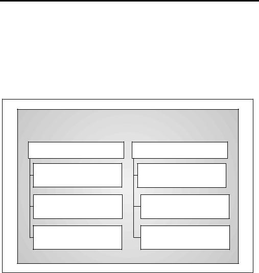
Figure 1–1 MICROLAB 500 System Components (items shown are not to scale)
STEP
PRIME
|
1 |
2 |
|
4 |
|
3 |
|
5 |
|
||
7 |
|
6 |
|
8 |
|
||
. |
9 |
|
|
|
|
||
0 |
|
|
|
Run
Stop
POWER
Dual Drive Unit Part # 35891 or 35892
(Microlab 530B/531C or 540B/541C)
STEP
PRIME
POWER
Single Drive Unit
Part # 35890 (Microlab 510B/511C)
Controller Unit and Cord
Part # 35893
(not with 500C models)
Power Cord
Part # 6541000 or 355010
Shipping Kit
Part # 35792 (Microlab 510B)
Part # 35793 (Microlab 530B)
Part # 35794 (Microlab 540B)
Manual
Part # 69176
Chapter 1 Getting Started |
1 –3 |

Table 1–2 lists the components that make up the MICROLAB 500B Shipping Kit (shown as a box in Figure 1–1). Figure 1–2 shows these components.
Table 1–2 MICROLAB 500B Shipping Kit
Shipping Kit* |
Valve Part # |
Hand Probe Part |
Small Parts Kit |
Tubing Kit |
Part # |
|
# |
Part # |
Part # |
|
|
|
|
|
MICROLAB |
HV Valve |
Concorde |
35888 |
35887 |
510B |
35825 |
Probe |
|
|
35792 |
|
35529 |
|
|
|
|
|
|
|
MICROLAB |
Diluter |
Concorde |
35888 |
35887 |
530B |
Valve |
Probe |
|
|
35793 |
35844 |
35529 |
|
|
|
|
|
|
|
MICROLAB |
Dispenser |
Dual Hand |
35888 |
35887 |
540B |
Valve |
Probe |
|
2 items |
35794 |
35842 |
35767 |
|
|
|
|
|
|
|
*The MICROLAB 500C is standard with only the valve. All other parts must be ordered separately.
1 –4 MICROLAB 510B/511C, 530B/531C, and 540B/541C User’s Manual
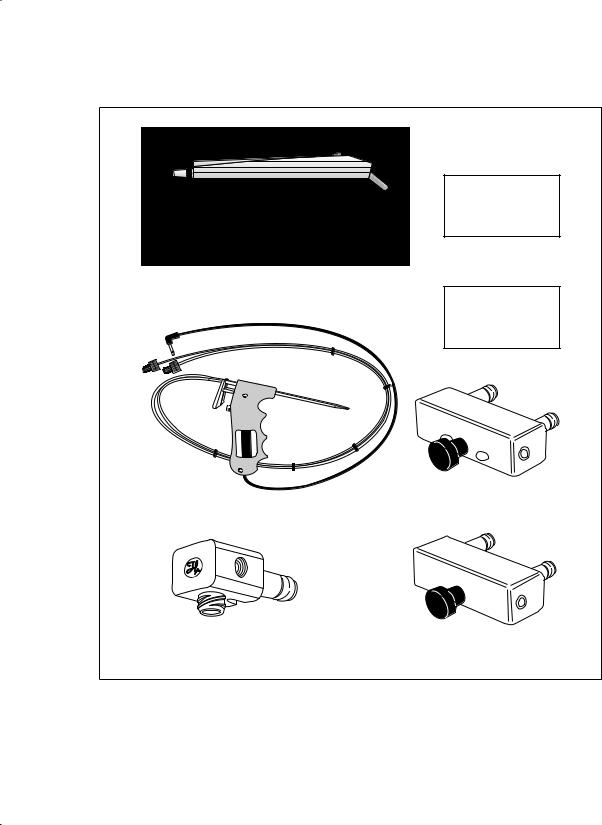
Figure 1–2 MICROLAB 500B Shipping Kit Components (items shown are not to scale)
|
Small Parts Kit |
|
|
Part # 35888 |
|
Concorde Probe |
|
|
Part # 35529 |
|
|
(Microlab 510B/511C or 530B/531C) |
|
|
|
Tubing Kit |
|
|
Part # 35887 |
|
|
Dispenser Valve |
|
Dual Hand Probe |
Part # 35842 |
|
Part # 35767 |
|
|
(Microlab 540B/541C) |
|
|
HV Valve |
Diluter Valve |
|
Part # 35825 |
||
Part # 35844 |
||
(Microlab 510B/511C) |
||
|
Chapter 1 Getting Started |
1 –5 |

Table 1–3 lists the components that make up the MICROLAB 500B Small Parts Kit (shown as a box in Figure 1–2). Figure 1–3 shows these components.
Table 1–3 |
Small Parts Kit #35888 (For All 500B Models) |
|||
|
|
|
|
|
Tubing Clips |
1 AMP Fuses |
Accessory |
Screws |
Tubing |
Part # |
Part # |
Holder |
Part # |
Reducers |
|
|
Part # |
|
Part # |
|
|
|
|
|
230010 |
1524-01 |
35783 |
16500 |
35770 |
2 items |
2 items |
1 item |
2 items |
2 items |
|
|
|
|
|
Figure |
1–3 Small Parts Kit (items shown are not to scale) |
|
|
(2) Tubing Clips |
|
|
Part # 230010 |
Accessory |
|
|
|
|
|
Holder |
|
|
Part # 35783 |
|
|
Tubing Reducers |
|
|
Part # 35770 |
|
(2) Screws |
(2) Fuses |
|
Part # 16500 |
|
|
Part # 1524-01 |
|
|
|
|
1 –6 MICROLAB 510B/511C, 530B/531C, and 540B/541C User’s Manual |
||
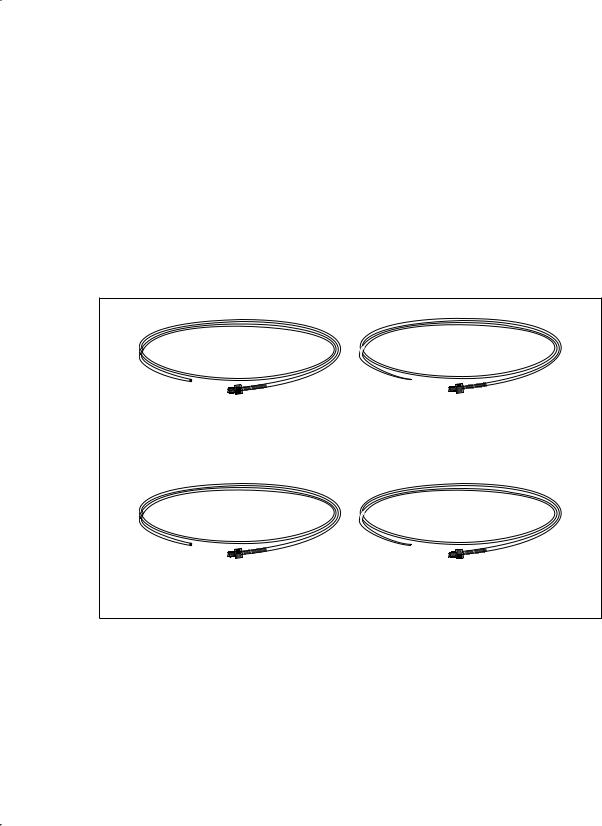
Table 1–4 lists the components that make up the MICROLAB 500 Tubing Kit (shown as a box in Figure 1–2). Figure 1–4 shows these components.
Table 1–4 |
Tubing Kit #35887 (For All 500B Models) |
|||
|
|
|
|
|
12 ga. x 650 mm |
|
18 ga. x 650 mm |
12 ga. x 900 mm |
18 ga. x 900 mm |
Fill Tubing (not |
|
Fill Tubing (not |
Dispense Tubing |
Dispense Tubing |
tapered) |
|
tapered) |
(tapered) |
(tapered) |
Part # |
|
Part # |
Part # |
Part # |
|
|
|
|
|
240000* |
|
240010* |
240360* |
240130* |
|
|
|
|
|
* M6 threaded hubs are used on all tubing.
Figure 1–4 Tubing Kit (items shown are not to scale)
12 ga. Fill Tubing |
12 ga. Dispense Tubing |
Part # 240000 |
Part # 240360 |
18 ga. Fill Tubing |
18 ga. Dispense Tubing |
Part # 240010 |
Part # 240130 |
For complete lists of syringes, accessories, and replacement parts for the MICROLAB 500, see Appendix C, Ordering Parts and Accessories for the MICROLAB 500.
Chapter 1 Getting Started |
1 –7 |

A Brief Introduction to the MICROLAB 500B
The MICROLAB 510B, 530B, and 540B systems each consist of three basic units. These units include:
•a drive unit
•a controller unit
•a hand probe
This section briefly describes these units and the individual components that comprise each unit. See Chapter 2, Installing the MICROLAB 500, for complete installation instructions; see Chapter 3, Using the MICROLAB 500, for complete usage instructions.
Drive Unit
The drive unit is the heart of each MICROLAB 500 system. The drive unit contains a precision drive motor, the syringe drive arms, the valve assembly, the power switches, and the connector receptacles. These features allow you to control other sub-assemblies, and together they create a very versatile and functional instrument.
Figure 1– 5 shows the front view of the MICROLAB 510B single syringe diluter/dispenser. In this figure, the controller unit rests on top of the drive unit and a syringe is attached to the syringe drive arm.
AWarning! This warning label appears on the front panel of the
ML500. It indicates that a pinch hazard exists when the syringe drive is moving. A
1 –8 MICROLAB 510B/511C, 530B/531C, and 540B/541C User’s Manual
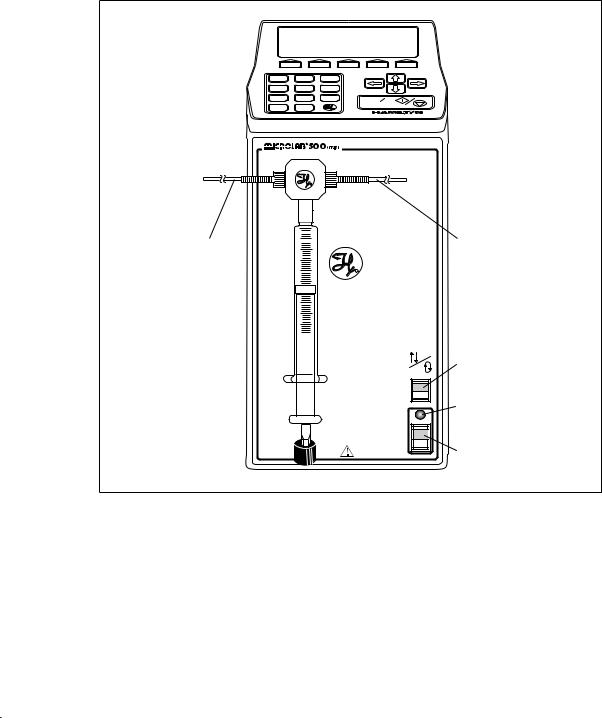
Figure 1–5 Front View of the MICROLAB 510B Single Syringe
Diluter/Dispenser
1 |
2 |
3 |
|
4 |
5 |
6 |
|
7 |
8 |
9 |
Run |
. |
0 |
|
Stop |
|
|
 Hand Probe
Connector
Receptacle
Input |
Output |
|
R |
STEP
PRIME
POWER
Step/Prime
Switch
Power
Indicator
Light
Power
On/Off
Switch
Chapter 1 Getting Started |
1 –9 |
 Loading...