

Page 1
®
5. OPERATION
4. INITIAL SETUP
* Only a 50 × 50 square solder pot is included in this product.
* The 75 × 75 square solder pot is an optional par t.
* This product meets China RoHS requirements.
* Specifications and design are subject to change without notice.
1. Install the J-shaped waste collector to the unit.
(Three-way installation is possible to meet your
operating needs.)
2. Cut the solder sticks into small pieces and put
them in the solder pot.
3. Plug the power cord into a grounded wall socket.
CAUTION
Make sure the power switch is off before plugging
in the power plug.
HAKKO FX-300 1
Spatula 1
J-shaped waste collector 1
Hexagon wrench 1
Instruction manual 1
2007.6
MA01622EbZ070606
Power consumption
Temperature range
Solder pot dimensions
Molten solder capacity
Weight
(w/o solder and cord)
Outer dimensions
50 × 50 Square
200 - 450°C (400 - 840°F)
50 (W) × 50 (D) × 43.5 (H) mm (2.0 × 2.0 × 1.7 in.)
0.85 kg (1.87 lb.)
1.7 kg (3.74 lb.)
75 × 75 Square
200 - 380°C (400 - 720°F)
75 (W) × 75 (D) × 52.5 (H) mm (3.0 × 3.0 × 2.1 in.)
1.2 kg (2.64 lb.)
Instruction Manual
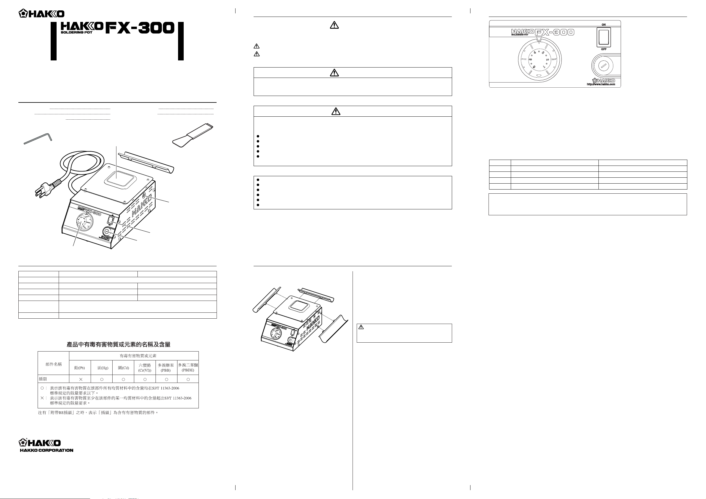
1. PACKING LIST AND PART NAMES
SOLDERING POT
Thank your for purchasing the HAKKO FX-300 soldering pot.
Please read this manual before operating the HAKKO FX-300.
Keep this manual readily accessible for reference.
Please check to make sure that all items listed
below are included in the package.
2. SPECIFICATIONS
100V - 195W, 110V - 220W, 120V - 200W, 220V - 190W, 230V - 205W, 240V - 215W
143 (W) × 100 (H) × 220 (D) mm (5.6 × 4.0 × 8.7 in.)
Copyright © 2007 HAKKO Corporation. All Rights Reserved.
HEAD OFFICE
TEL:+81-6-6561-3225 FAX:+81-6-6561-8466
http://www.hakko.com E-mail:sales@hakko.com
Please access to the following address for the other Sales affiliates.
http://www.hakko.com
Observe the following precautions to ensure safety.
3. SAFETY INSTRUCTIONS
Warnings, cautions and notes are placed at critical points in this manual to direct the operator’s
attention to significant items. They are defined as follows:
CAUTION : Failure to comply with a CAUTION may result in injury to the operator, or damage to the
items involved. Two examples are given below.
WARNING: Failure to comply with a WARNING may result in serious injury or death.
CAUTION
The molten solder in the solder pot is dangerous since it reaches about 450°C/842°F. The pot cover also
becomes a high temperature when the power is ON. Wrong handling may cause burns or fire. Be sure to
observe the following precautions.
Use this product on highly stable metal workbench. Never use it near paper or other flammable materials.
Inform others in the area that the product is hot and should not be touched.
Never put water in the solder pot as this will cause solder to spatter out of the solder pot.
Tu rn the power off when not in use, or left unattended.
Before changing parts or storing the unit, be sure to turn the power off and allow the unit to cool to room
temperature.
Observe the following precautions to prevent accidents or damage to the unit.
Do not use the HAKKO FX-300 for applications other than soldering.
Do not modify the HAKKO FX-300.
Use only genuine HAKKO replacement parts.
Do not allow the HAKKO FX-300 to become wet, or use it with wet hands.
Be sure the work area is well ventilated. Soldering produces smoke.
Do not do anything else that might be dangerous.
WARNING
WARNING
When the power is ON, the temperature of the melted solder in the solder pot is approximately
450°C/842°F. Before changing the solder pot, be sure to unplug the power cord and let the solder
and the unit cool to room temperature.
Solder pot
J-shaped waste collector
Spatula
Solder pot mounting
screws (both sides)
Fuse
Power switch
Temperature regulator knob
Hexagon wrench
Power cord
Knob
1-3
3-4
4-5
5-6
Temperature (
50 × 50 Square
)
Approximately 200°C (400°F)
Approximately 300°C (570°F)
Approximately 400°C (750°F)
Approximately 450°C (840°F)
Temperature (
75 × 75 Square
)
Approximately 200°C (400°F)
Approximately 300°C (570°F)
Approximately 350°C (660°F)
Approximately 380°C (720°F)
Temperature regulator knob
The set temperature can be changed with the temperature regulator knob.
Tu r ning the knob clockwise increases the set temperature and turning the knob
counterclockwise decreases the set temperature.
1. Turn the power switch ON.
2. The temperature control is started, causing the temperature to increase.
NOTE:
Temperature depends on a soldering pot. Please use the table above as a guide.
Measure an exact temperature by the FG-100 or the FG-101 with an applicable temperature probe if
necessary.
Page 2
Loosen
Loosen
Pull out
Fig. 1
Fig. 2
Fig. 3
CHECK
CHECK!
CHECK
Fig. 4
Pan head screw
M3 × 8 (4)
Button bolt
M4 × 35 (2)
Tr uss screw
M4 × 5 (11)
External tooth
lock washer
Nominal size 4 (2)
Sems screw
M4 × 8 P3 (4)
External tooth
lock washer
Nominal size 4 (1)
Pan head screw
M3 × 8 (2)
Nut M3 (1)
4
5
6
13
9
14
18
10
17
15
16
11
12
3
7
2
8
1
3
3
Left
Right
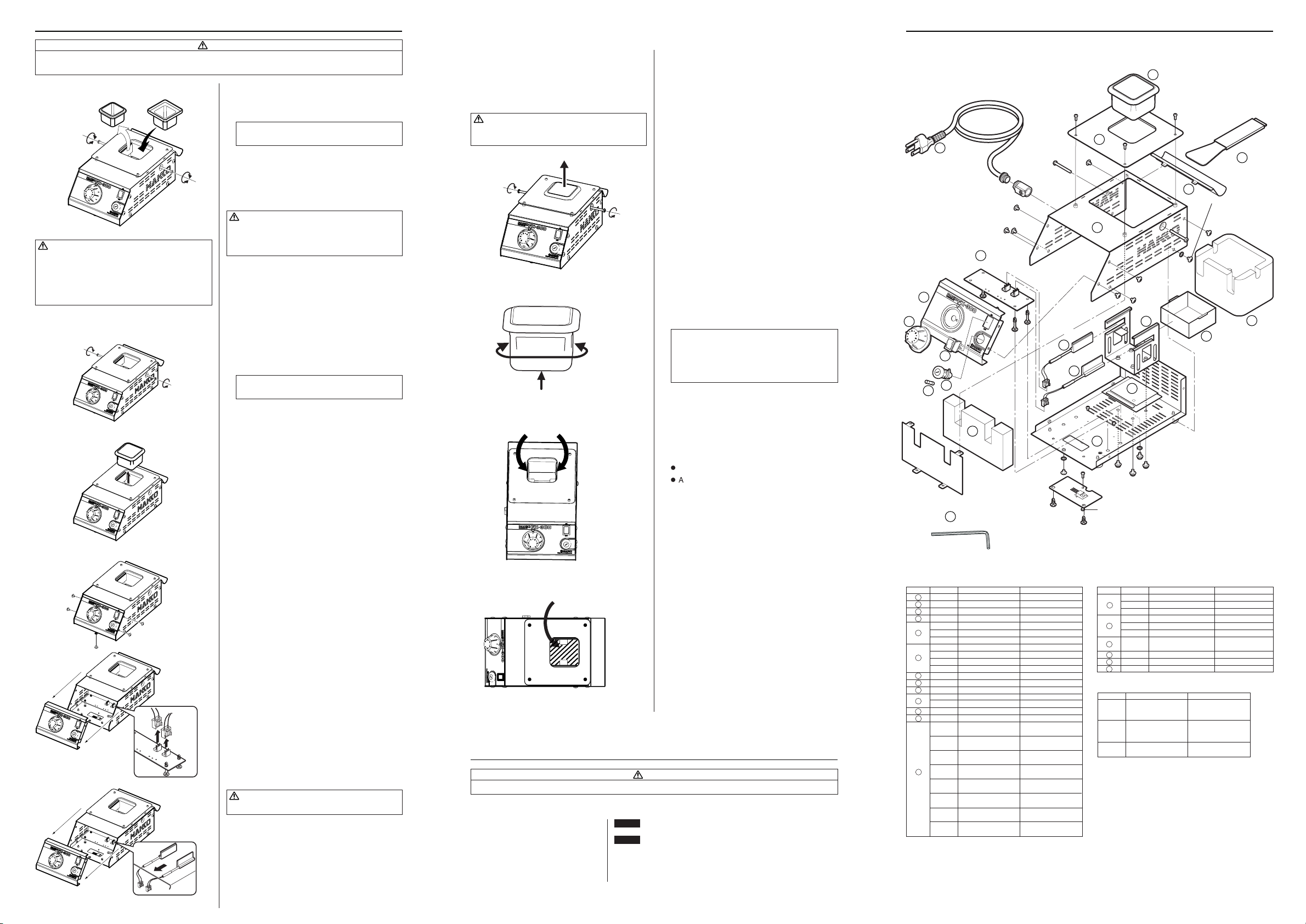
8. PARTS LIST6. MAINTENANCE
WARNING
Unless otherwise directed, carry out these procedures after turning the power switch OFF,
unplugging the power plug and waiting for both the unit and the solder to sufficiently cool down.
● Changing the solder pot
WARNING
When the power is ON, the temperature of the
melted solder in the solder pot is approximately
450°C/842°F. Before changing the solder pot, be
sure to unplug the power cord and let the solder
and the unit cool to room temperature.
● Replacing the heating element
● Daily Check
Solder gradually corrodes and makes holes through
the stainless solder pot, which can lead to solder
leakage from the holes.
Daily check and replacement (if necessary) of the
solder pot is recommended to ensure comfortable
and safe execution of work.
CAUTION
Make sure that the solder pot has sufficiently
cooled down before performing the daily check.
1. Using the hexagon wrench (provided with the
HAKKO FX-300) to loosen the screws on both
sides of the unit.
NOTE:
Screws do not have to be removed.
2. Pull out the solder pot.
3. Insert a new solder pot and then tighten the
screws on both sides.
CAUTION
Check that the solder pot has been locked now.
Otherwise, the temperature may not increase
properly.
1. Loosen the screws on both sides of the unit.
(Fig. 1)
NOTE:
Screws do not have to be removed.
2. Pull out the solder pot. (Fig. 2)
3. Remove the setscrews (5 pieces) on the unit.
(Fig. 3)
4.
Slide the front panel frontward, disconnect the two
connectors (Fig. 4) from the connector circuit
board, and then pull out the units of the heating
elements (Fig. 5).
5. Insert the right and left heating elements in the
reverse procedure to removing the heating
elements.
CAUTION
The heating element is a discrete type.
How to check
1. Loosen two mounting screws on both sides of
the unit to pull out the solder pot. (Fig. 1)
2. Check for holes or leaks by visually inspecting
the surface of the solder pot. (Fig.2)
NOTE:
Visually inspect sides and bottom of the solder
pot. The life of the solder pot can be increased
if the pot is reinstalled with its orientation being
changed by 90 degrees.
3. Check the following areas for solder sticking.
l
Overflow tray
l
Around the heater of the unit, insides of the
heat insulator (Fig.3 and Fig.4)
7. TROUBLE SHOOTING GUIDE
WARNING
Before checking the inside of the FX-300 or replacing parts, be sure to disconnect the power plug.
● The unit does not operate when the
power switch is turned on.
Fig. 5
Fig. 4
Fig. 3
Fig. 2
Fig. 1
CHECK : Is the power cord and/or the connection plug disconnected?
ACTION : Connect it.
CHECK : Is the fuse blown?
ACTION :Investigate why the fuse blew and then replace the fuse. If the
cause can not be determined, replace the fuse. If the fuse blows
again, send the unit in for repair.
Item No.
1
2
3
4
5
6
7
8
9
10
11
12
13
Part No.
B3382
B2918
B2916
B3383
B3385
B3386
B3387
B2705
B2468
B2922
B3045
B3384
B2927
B2928
B1487
B2604
B1134
B3348
B1238
B1795
B1796
B2913
B2914
B1797
B1798
B3046
Part Name
Cover
Overflow tray
Heat insulator
Front panel
P. W . B .
P. W . B .
P. W . B .
Midget fuse/125V-5A
Fuse/125V-5A
Fuse/250V-5A
Fuse/250V-5A CE
Chassis
Solder pot support
Solder pot tray
Power switch
Power switch
Fuse holder
Knob
Power cord, 2 wired
cord & flat 2 pin plug
Power cord, 3 wired
cord & American plug
Power cord, 3 wired
cord but no plug
Power cord, 3 wired
cord & BS plug
Power cord, 3 wired
cord & Chinese plug
Power cord, 3 wired
cord & European plug
Power cord, 3 wired
cord & Australian plug
Power cord, 3 wired
cord & BS plug CE
Specifications
With membrane sheet
100 - 110V
120V
220 - 240V
100 - 110V
120V
220 - 240V
230V CE, KTL
With rubber feet
100 - 120V
220 - 240V
KTL, CE
● FX-300 Soldering pot
Item No.
14
15
16
17
18
19
Part No.
A1551
A1553
A1549
A1552
A1554
A1555
A1517
B2919
B2932
B1417
Part Name
Heating element/Right
Heating element/Right
Heating element/Right
Heating element/Left
Heating element/Left
Heating element/Left
Solder pot
J-shaped waste collector
Spatula
Hexagon wrench
Specifications
100 - 110V
120V
220 - 240V
100 - 110V
120V
220 - 240V
50 × 50 × 43.5(mm)
/2.0 × 2.0 × 1.7(in.)
● Replacement parts
Part No.
A1539
A1540
A1518
Part Name
Solder pot
Solder pot
Solder pot
Specifications
Special coating
50 × 50 × 43.5(mm)
/2.0 × 2.0 × 1.7(in.)
Special coating
75 × 75 × 52.5(mm)
/3.0 × 3.0 × 2.1(in.)
75 × 75 × 52.5(mm)
/3.0 × 3.0 × 2.1(in.)
● Optional parts
19
 Loading...