

Page 1
Please access to the following address for the other Sales affiliates.
http://www.hakko.com
WARNING
If output setting is over 70%, the handpiece and holder can be very hot. Please be
sure to turn on the auto-sleep function before use.
(On HAKKO FT-801, please be sure to connect the station and holder with included
connecting cable in order for auto-sleep to function properly.)
WARNING
Operating above 80% output setting can cause stress to the heating element and
shorten the life of the blades. Use 80% and above power only when necessary.
When not using the handle, be sure to place it in the holder.
CAUTION
Since the blades will become hot, place the handle on the handle holder when it is
not being used.
THERMAL WIRE STRIPPER
FT-8004
(with holder part)
Thank you for purchasing HAKKO products.
When using the product, please read this manual
and follow the instruction to change the parts.
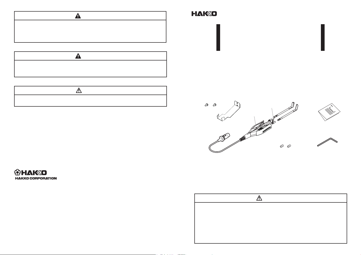
PACKING LIST AND PART NAMES
●
Please make sure that all items listed below are included in the package.
SEMS screw P2
Lead adjuster
Handle
THERMAL WIRE STRIPPER
FT-802
HEAD OFFICE
4-5, Shiokusa 2-chome, Naniwa-ku, Osaka 556-0024 JAPAN
TEL:+81-6-6561-3225 FAX:+81-6-6561-8466
http://www.hakko.com E-mail:sales@hakko.com
OVERSEAS AFFILIATES
U.S.A.: AMERICAN HAKKO PRODUCTS, INC.
TEL: (661) 294-0090 FAX: (661) 294-0096
Toll Free (800)88-HAKKO
4 2 5 5 6
http://www.hakkousa.com
HONG KONG: HAKKO DEVELOPMENT CO., LTD.
TEL: 2811-5588 FAX: 2590-0217
http://www.hakko.com.cn
E-mail:info@hakko.com.hk
SINGAPORE: HAKKO PRODUCTS PTE., LTD.
TEL: 6748-2277 FAX: 6744-0033
http://www.hakko.com.sg
E-mail:sales@hakko.com.sg
© 2018-2 019 HAKKO Corpora tion. All Rights Re served.
Company an d product names are tr ademarks or registere d
trademarks o f their respective
companies.
MA03051XZ190607
2019.6
Holder part
HAKKO FT-8004
Blade (not included)
Hexagon socket set screw
Instruction Manual
Hexagon wrench
PACKING LIST
HAKKO FT-8004 ...................................1
Holder part (for use with C5012) ...........1
SEMS screw P2 (M3×6 for holder part) ... 2
Hexagon wrench (1.27 mm) ..................1
Instruction Manual ................................1
Hexagon socket set screw (M2.5×2.5)
Precautions Regarding Electrostatic Protection
CAUTION
This product includes features such as electrically conductive plastic parts and
grounding of the handle and station as measures to protect the device to be
soldered from the effects of static electricity.
Be sure to observe the following instructions:
The handle and other plastic parts are not insulators, they are conductors. When
replacing parts or repairing, take sufcient care not to expose live electrical parts or
damage insulation materials.
Be sure to ground the unit during use.
....2
Page 2

How to attach the holder part (using C5012 handpiece holder)
Lead adjuster
Handle cover L
Insulating cover
Fig.1
Fig.2
Fig.3
Fig.4
Fig.5
(M2.5×2.5)
●
CAUTION
Please be sure to use the included holder part.
Remove the holder part from
the C5012 handpiece holder
(included with the HAKKO FT-
801). Attach the B5247 holder
part (included with the HAKKO
FT-8004). Please use included
SEMS screws for assembly.
Installing the blades
●
1. Insert the blades fully and match the
V-groove on the blades to the V-groove
on the mounting fl ange. Push until
blades are fl ush with mounting fl ange.
2. Insert the hexagon socket set screws but do
not tighten.
Blades will not heat up unless both blades are
fully inserted. Be sure to use the blades as a set.
3. Adjust and align the blades manually then
tighten the hexagon socket set screws with
the hexagon wrench to secure the blades.
Removing the blades
●
─ NOTE ─
Holder part
V-groove
Hexagon wrench
Holder part
(for HAKKO FT-8004)
Hexagon socket set screw
CAUTION
When pulling out or inserting blades, be sure that the power is switched off.
Before pulling out the blades, check that the blades have cooled down suf ciently.
Attaching the lead adjuster
●
1. Remove the insulating cover from
the handle cover L-side as shown in
gure 1 (side with HAKKO FT-8004
logo) and remove the screw from the
handle cover L-side.
2. Remove the handle cover L.
3. Align the lead adjuster as shown in
gure 3 in the designated channel in
the handle cover L. Tighten lightly
in place using mounting bracket and
screw.
4. Firmly t the bottom side of the
insulation cover to the handle cover
as shown in gure 4.
5. Attach handle cover L to the
handpiece at the bottom and tighten
the screw for handle cover L.
Reattach insulating cover to the top
side of the handle cover L. Adjust the
length of the lead adjuster and rmly
tighten the screw.
─ NOTE ─
Pay attention to the direction of the
blades when attaching the lead adjuster.
(See the following gure.)
Attach the lead adjuster so that the
adjuster plate end is in parallel with the
blade surface.
Loosen and remove the hexagon socket set
screw xing the blades.
As illustrated below,
pull the blade straight out.
The lead adjuster can be removed with
the handle cover attached to the handle.
 Loading...