

Page 1
®
High-output, temperature controlled
soldering station
Instruction Manual
●
Thank you for purchasing the FP-102 soldering station. This
high-output, temperature controlled soldering station uses a
composite tip, incorporating heater and sensor functions into
one element. Several process control features unique to the
FP-102 make it applicable to a broad range of soldering
applications.
Please read this manual before operating the FP-102 . Keep
this manual readily accessible for reference.
●
TABLE OF CONTENTS
1. P ACKING LIST ...............................................................1
2. SPECIFICA TIONS ..........................................................1
3. WARNINGS, CAUTIONS, NOTES AND EXAMPLES.....2
4. P AR T NAMES.................................................................3
5. INITIAL SETUP ..............................................................3
6. OPERA TION...................................................................5
7. P ARAMETER SETTINGS...............................................6
8. MAINTENANCE .............................................................7
9. ERROR MESSAGES......................................................9
10. TROUBLE SHOOTING GUIDE ....................................10
1 1. PAR TS LIST..................................................................11
12. TIP STYLES .................................................................13
13. WIRING DIAGRAM.......................................................15
Page 2
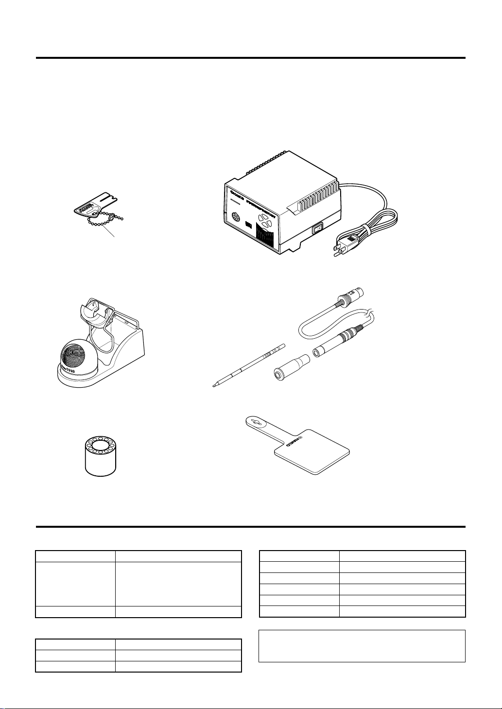
1. P ACKING LIST
Please check to make sure that all items listed below are
included in the FP-102 package.
FP-102 soldering station.................................1
FM-2021 connector assembly .....................1
Sleeve assembly ............................................ 1
Control card, with chain ..................................1
Control card
Card chain
Tip (not included)
Heat resistant pad...........................................1
Tip tray ............................................................1
Iron holder.......................................................1
Cleaning wire ..................................................1
Instruction manual ..........................................1
M
O
D
E
L
FP-102
7
.5
7
.0
8
.0
6
.5
FP-102 Soldering station
FM-2021 Connector assembly
Iron holder
Tip tray
2. SPECIFICA TIONS
● FP-102 soldering station
Power consumption
Temperature range
Temperature stability
● Station
Output
Dimensions(W × H × D)
Weight (w/o cord)
1
75 W
The four segment lights on the front
panel indicate the heat range selected
for the FP-102 (6.5 = ~650°F. [343°C];
7.0 = ~700°F. [371°C]; 7.5 = ~750°F.
[399°C]; 8.0 = ~800°F. [427°C]).
±9°F (±5°C) at idle temperature
24 V
120 × 93 × 140 mm (4.7 × 3.7 × 5.5 in.)
1,400 g (3.1 lb.)
Heat resistant pad
● Soldering iron
Power consumption
Tip to ground resistance
Tip to ground potential
Length, less cord
Weight, less cord
Length of cord
NOTE:
This product is protected against electrostatic discharge.
Specifications and design are subject to change without notice.
Sleeve assembly*
*Yellow, orange or blue sleeve
assembly is included.
70 W (24 V)
< 2 Ω
< 2 mV
188 mm (7.4 in.) with 2.4D tip
30 g (0.067 lb./1.07 oz.) with 2.4D tip
1.2 m (4 ft)
Page 3
3.
W ARNINGS, CAUTIONS, NOTES AND EXAMPLES
Warnings, cautions and notes are placed at critical points in this manual to direct the
operator’s attention to significant items. They are defined as follows:
WARNING: Failure to comply with a WARNING may result in serious injury or
death.
CAUTION: Failure to comply with a CAUTION may result in injury to the
operator, or damage to the items involved. (Two examples are
given below.)
NOTE: A NOTE indicates a procedure or point that is important to the process being
described.
EXAMPLE: An EXAMPLE is given to demonstrate a particular procedure, point or
process.
CAUTION
When power is ON, the tip will be HOT (between 300-450°C. [~572-840°F.])
To avoid injury or damage to personnel and items in the work area, observe the
following:
● Do not touch the tip or the metal parts near the tip.
● Do not allow the tip to come close to, or touch, flammable materials.
● Inform others in the area that the unit is hot and should not be touched.
● Turn the power off when not in use, or left unattended.
● Turn the power off when connecting the FM-2021 or storing the FP-102.
● Do not remove or damage the bar code sticker.
CAUTION
To prevent accidents or damage to the FP-102, be sure to observe the following:
● Do not use the FP-102 for applications other than soldering.
● Do not allow the FP-102 to become wet, or use it with wet hands.
● Do not modify the FP-102.
● Use only genuine Hakko replacement parts.
● Do not bend or damage the control card. If the card does become damaged, do not force the
card into the station slot.
● Do not strike the iron against hard objects to remove excess solder. This may damage the
iron.
● Remove power and iron cords by holding the plug, not the wires.
● Be sure the work area is well ventilated. Soldering produces smoke.
2
Page 4
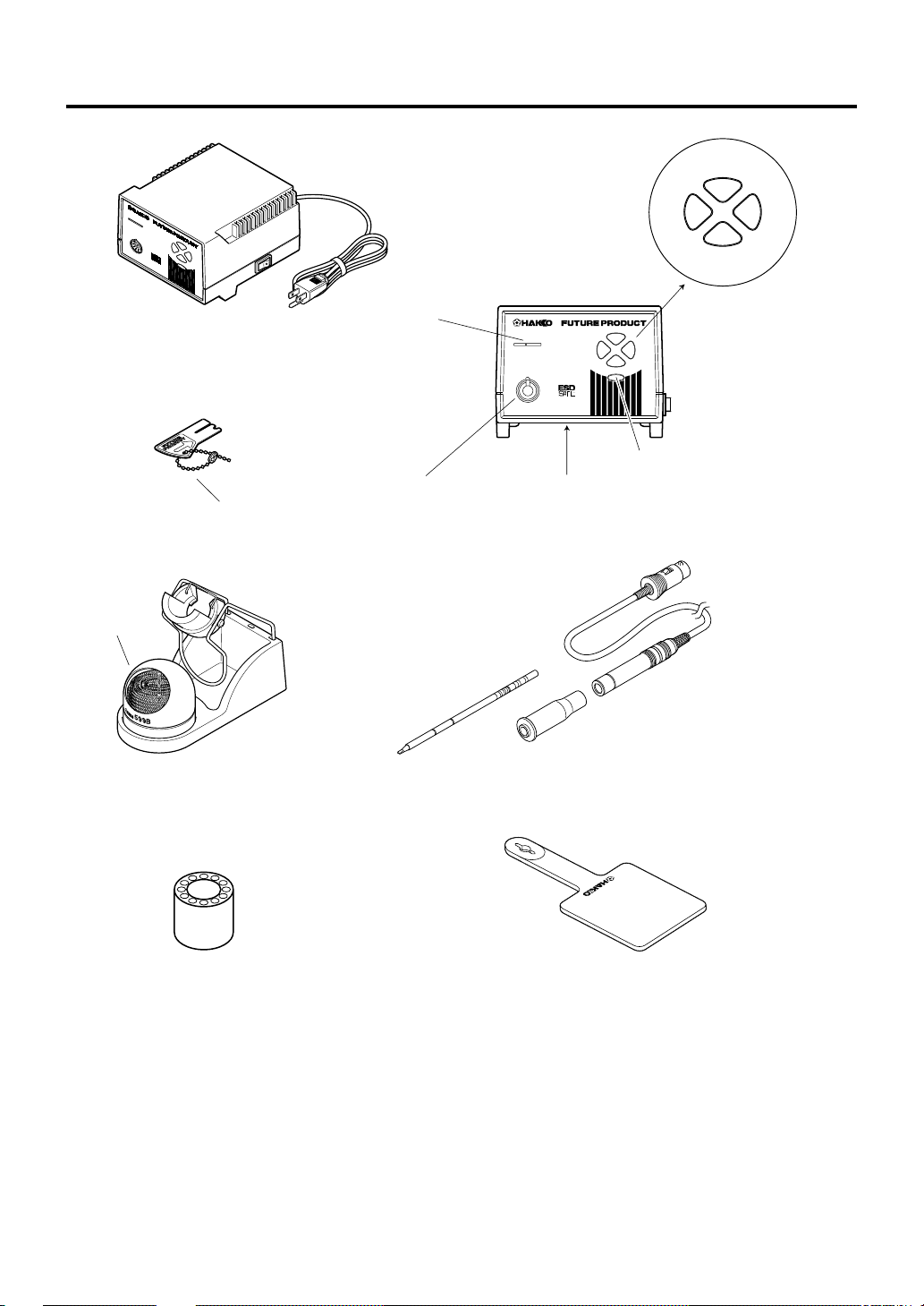
4. PART NAMES
blue
7.5
FP-102 Soldering station
Tip cleaner
MO
D
EL
FP-102
7
.5
7
.0
8
.0
6.5
Control card
Card chain
Card slot
Receptacle
Tip (not included)
yellow
®
MODEL
FP-102
7.5
8.07.0
6.5
The heat range selector button
Auto power shutoff switch
(on the bottom front of the case)
FM-2021 Connector assembly
6.5
green
red
8.07.0
Sleeve assembly
Iron holder
Tip tray
Heat resistant pad
3
Page 5
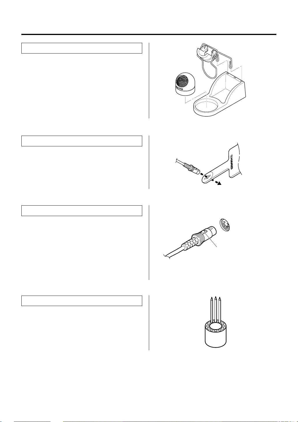
5. INITIAL SETUP
● Iron holder
Assemble as shown:
● Insert the holder assembly securely into
the Iron holder base.
● Connector cord
Pass the connector cord through the hole in the
heat resistant pad.
● Soldering station
1. Insert the connector cord into the receptacle
at the front of the station.
2. Plug the power cord into a grounded wall
socket. The FP-102 is protected against
electrostatic discharge and must be
grounded for full efficiency.
● Tip tray
Place spare tips in the tip tray.
Receptacle
Push the connector in as far as
it will go. When the plug clicks,
it is fully inserted.
4
Page 6

6. OPERA TION
OPERATION
1. Turn the power switch ON.
2. A heat range indicator (one of the four
segment buttons, indicating the selected
range) will blink.
3. When the set temperature is reached, the
buzzer alarm sounds indicating it is ready for
use. The indicator lamp remains on steadily.
● Control card
● Changing the heat range
1. Insert the control card into the slot in the
front of the unit.
As previously noted, the four segment
lights on the front panel indicate the heat
range selected for the FP-102 (6.5=
~650°F. [343°C]; 7.0= ~700°F. [371°C];
7.5= ~750°F. [399°C]; 8.0= ~800°F.
[427°C]. The ranges are approximate
values only; the actual tip temperature
depends upon tip geometry and mass.
These lights are indicators; one must
press the “heat range” button, located
below the indicators, to change range.
NOTE:
When not in use, place the soldering iron to the iron
holder.
Each FP-102 comes with a small card, which
inserts into the Card slot on the front of the unit.
This card is used when changing heat ranges.
Any FP-102 card can be used with any FP-102
soldering station.
CAUTION:
The control card must be inserted into the card slot in the
correct direction for data to be entered.
2. Press the heat range selector button. Each
time this button is pressed a different heat
range indicator lamp will light. It will blink
slowly until the set range is reached; once at
temperature, it will remain on steadily.
3. Removing the card.
When the station is on and the control card
is in the station, the temperature can be
changed any time.
4. When the alarm sounds and the heat range
indicator lamp starts lighting, the station is
ready for use.
5
®
7.5
MODEL
FP-102
The heat range selector button
8.07.0
6.5
7.5
8.07.0
6.5
When power is switched off the selected heat
range is stored in memory.
Page 7

● Using the iron holder
Remove any excess solder from the tip
by thrusting the tip into the cleaning wire.
(Do not wipe the tip against the wire. This
may cause molten solder to spatter.)
When the wire become dirty or loaded with
solder, turn the wire until a clean surface is
presented.
When changing the cleaning wire, lift the
case top vertically to prevent solder debris
from falling out.
● Replacing the tip
Removing and inserting the tip:
Removing the tip: Hold the sleeve assembly
to remove the connector.
Remove the tip from the sleeve assembly.
(If the tip is hot, hold it with the heat-resistant
pad.)
Inserting the tip: Hold the head part and
insert the tip into the sleeve assembly. Push
until the sleeve assembly touches the ring
round the tip; at this point the tip should not
be forced further into the sleeve assembly.
Put the tip into the connector.
Insert the new tip firmly into the connector.
1
2
W
0
0
-2
7
-
M
V
F
4
2
®
Hold the sleeve assembly at the front to remove tip.
Hold these parts to insert tip into sleeve assembly.
Hold and squeeze this part to insert into the connector.
There are no orientation requirements.
The tip can be very HOT. Use the heat-resistant pad for
handling hot tips, but do not hold the hot portion of the tip,
even with the pad, for a long time.
7. PARAMETER SETTINGS
Auto power shutoff
This is an optional setting. When it is activated
and the soldering iron is not used for 30
minutes, the power to the heating element is
shut off automatically, the alarm will sound
three times and the selected heat range lamp
will light slowly. When the temperature
decreases to 100°C/212°F, the heat range
indicator lamps light in a slow clockwise
sequence. If the station is left in this mode, the
'alarm' will continue to sound every thirty
minutes. To resume soldering, cycle the power
switch OFF, then ON. The power will be turned
on automatically if the heat range selector
button is pressed before the temperature
decreases to 100°C/212°F.
The auto power shutoff switch is on the bottom
front of the case. To turn this function ON ,set
the switch to the' I ' position. (OFF is reverse.)
CAUTION:
6
Page 8

8. MAINTENANCE
● Tip maintenance
1. Tip temperature
High temperatures shorten tip life and may
cause thermal shock to components. Always
use the lowest possible temperature when
soldering. The excellent thermal recovery
characteristics of the FP-102 ensure effective
soldering at low temperatures.
2. Cleaning
3. After use
4. When the unit is not being used
and the auto power shutoff is not
active.
5. Inspecting and cleaning the tip
Always clean the soldering tip before use to
remove any residual solder or flux adhering to it.
Use the 599B tip cleaner (provided with the FP-
102) or use a clean and moist cleaning sponge
part no. A1495. Contaminants on the tip have
many deleterious effects, including reduced
heat conductivity, which contribute to poor
soldering performance.
Always clean the tip and coat it with fresh solder
after use. This guards against oxidation.
Never allow the unit to idle at a high temperature
for extended periods. This will allow the tip to
become oxidized. Turn the power switch OFF. If
it is to be out of service for several hours, it is
advisable to pull the power plug as well.
This procedure, if followed daily, will materially
add to tip life.
a. Set the heat range to 6.5.
b. When the temperature stabilizes, clean the
tip (see 2, above) and check the condition of
the tip. If the tip is badly worn or deformed,
replace it.
c. If the solder plated part of the tip is covered
with black oxide, apply fresh solder, containing flux, and clean the tip again. Repeat
until all the oxide is removed, then coat the
tip with fresh solder.
CAUTION:
NEVER file the tip to remove oxides!
d. Turn the power OFF and remove the tip. Set
the tip aside to cool.
7
Page 9

● Checking Procedure
WARNING:
Unless otherwise directed, carry out these procedures with the power switch OFF and the power UNPLUGGED.
■Check for a broken heater or
sensor
■Check the grounding line
2
5
3
7
4
1
8
6
■ Checking the connection cord
for breakage
Black
Green
Red
White
Blue
1. Check for a broken heater or sensor
Measure the resistance
across this position.
1Y100CB3
T7-D24
Verify the electrical integrity of the heater and
sensor.
Measure the resistance of the heater and
sensor while at room temperature (15 to 25°C;
59 to 77°F). It should be 8Ω±10%. If the
resistance exceeds these limits, replace the tip.
1. Unplug the connection cord from the station.
2. Measure the resistance value between Pin 2
and the tip.
3. If the value exceeds 2Ω (at room temperature),
perform the tip maintenance described on P.7. If
the value still does not decrease, check the
connection cord for breakage.
1. Remove the soldering tip and the sleeve
assembly.
2. Turn the front piece of the FM-2021 clockwise
and remove the cover.
3. Measure the resistance values between the
connector and the lead wires at the socket as
follows:
Pin 1 – Red Pin 2 – Green
Pin 3 – Black Pin 5 – White
If any value exceeds 0Ω, replace the FM-2021.
8
Page 10

9. ERROR MESSAGES
● System Error
7.5
8.07.0
6.5
● Sensor Error
7.5
8.07.0
6.5
● Heater terminal short circuit
error
7.5
When the power is turned on, the system
automatically checks its memory and the stored
program. If a problem is found, all the heat
range indicator lamps will light and the tip will
not heat.
When there is the possibility that a failure has
occurred in the sensor or heater (including the
sensor circuit), the heat range indicator lamp
will blink rapidly and the heater is shut down.
NOTE:
‘Sensor error’ also occurs if the tip is not inserted
properly.
All the heat range indicator lamps will blink, and
the alarm will sound continuously. Possible
causes are: the tip is inserted the wrong way , an
incompatible tip is inserted, or a foreign object
is in the connector.
8.07.0
6.5
● Soldering iron error
7.5
8.07.0
6.5
The yellow and red heat range indicator lamps
will blink if the connector cord is not attached to
the station OR the wrong soldering iron is
connected.
CAUTION:
Do not connect the FM-2022 or FM-2023 with the FP-
102.
9
Page 11

10. TROUBLE SHOOTING GUIDE
WARNING:
• Before opening the FP-102, or replacing parts, be sure to disconnect the power plug. Failure
to do so may result in electric shock.
● The unit does not
operate when the power
switch is turned on.
● The tip does not heat up.
7.5
•‘Sensor error’
displayed.
8.07.0
is
6.5
● Solder does not wet the
tip.
● The tip temperature is
too high.
● The tip temperature is
too low.
CHECK : Is the plug disconnected?
ACTION
CHECK : Is the tip inserted properly?
ACTION
CHECK : Is the connection cord and/or the heater/sensor broken?
ACTION
CHECK : Is the tip contaminated with oxide?
ACTION
CHECK : Is the connection cord broken?
ACTION
CHECK : Is the tip contaminated with oxide?
ACTION
: Connect it.
: Insert the tip completely.
: See the appropriate section of this manual regarding how
to check the connection cord and/or the heater/sensor for
breakage.
: Remove the oxide (see “Tip maintenance” on P. 7).
: See “Checking the connection cord for breakage” on P. 8.
: Remove the oxide (see “Tip maintenance” on P. 7).
● The soldering iron error,
yellow and red lamp
blink.
● Heater terminal short
7.5
circuit error
8.07.0
is
6.5
displayed
CHECK : Is the wrong soldering iron connected? Or the FM-2021
plug disconnected?
ACTION
CHECK : Is the tip for FM-2021?
ACTION
: Turn off the power switch, re-connect the FM-2021
soldering iron, then turn on the power switch.
: Turn the power switch OFF and insert genuine FM-2021 tip.
Turn the power switch ON.
10
Page 12

11. P ARTS LIST
NOTE:
Spare or repair parts do not include
mounting screws, if they are not
listed on the description. Screws
must be ordered separately.
1
Tapping screw
2.6 × 6 (1)
Tapping screw
2.6 × 8 (3)
3
5
Tapping screw
3 × 8 (3)
Binding head
tapping screw
3.5 × 45 (4)
Pan head screw
M4 × 6 (2)
11
External tooth
lock washer
nominal size 4
2
● FP-102 Station
Item
Part No.
No.
1
B2839
B2861
2
B2835B
3
4
B2836
5
B2837
6
B2838
7
B2852
8
B1319
9
B2015
10
B2103
11
B2227
12
B2224
11
M
O
D
E
L
F
P
-1
0
2
7.0
Part Name
Control card
Front panel
P.W.B. (temperature
control and connector)
Transformer
Upper case
Lower case
Power switch
Power cord
Cord stopper
Wiring board for switch
Grounding plate
Fuse
3
7.5
8.0
6.5
Specifications
with LED lens and
shieding plate
120V
with rubber foot
3 wired cord & American plug
2A (UL)
4
Tapping screw
3 × 12 (1)
8
9
12
10
7
6
Tapping screw
4 × 12 (4)
Page 13

3
4
2
1
Item No. Part No.
5
1 3
FM2021-01
,,
1
FM2021-02
2
B2770
B2765C
3
B2768C
B2769C
5
3
1
2
6
5
4
4
5
B2300
Iron Holder
•
Item No.
1
•
Item No.
Part No.
6
~
634-01
Iron Holder Parts
Part No.
B2786
1
2
B2790
3
B2791
4
B2792
5
599B-02
6
599-029
7
B2756
Part Name
Conversion kit
Connector assembly
Connector cover
Sleeve assembly
Sleeve assembly
Sleeve assembly
Tip
Heat resistant pad
Part Name
Iron holder
Part Name
Holder for
iron receptacle
Iron receptacle
Retaining clip
Iron holder base
Tip cleaner
Cleaning wire
Tip tray
Specifications
3
is yellow
Yellow
Orange
Blue
See section
'12. TIP STYLES'
Specifications
Specifications
With screw
With rubber foot
7
12
Page 14

12. TIP STYLES
21
115
(4.53)
139
(5.47)
ø5.5
(0.22)
T7-D08 SHAPE-0.8D Chisel T7-D12 SHAPE-1.2D Chisel T7-D16 SHAPE-1.6D Chisel T7-D24 SHAPE-2.4D Chisel
0.5
(0.02)
(0.12)
ø0.8
(0.03)
3
9.5
(0.37)
0.5
(0.02)
4.3
(0.17)
ø1.2
(0.05)
10
(0.39)
0.5
(0.02)
T7-D32 SHAPE-3.2D Chisel T7-D4 SHAPE-4D Chisel T7-D52 SHAPE-5.2D Chisel
(0.008)
30°
R0.2
.00
(0
(0.16)
R
0
(0.06)
ø4
(0.16)
4
7.5
(0.3)
1.2
(0.05)
T7-LI SHAPE-LI Long Sharp Conical
.2
9.5
(0.37)
T7-C1 SHAPE-1C Bevel
1.6
8)
7.9
(0.31)
ø3.2
(0.13)
0.5
(0.02)
1.6
(0.06)
T7-B2 SHAPE-2B Conical
R0.5
(0.02)
10
(0.39)
(0.2)
5
0.5
(0.02)
T7-I SHAPE-I Sharp Conical
T7-JL02 SHAPE-0.2RLB Bent T7-JS02 SHAPE-0.2RSSB Bent
7.5
(0.3)
30°
R0.2
(0.008)
9.3
(0.37)
3.5
(0.14)
(0.31)
R0.2
(0.008)
ø1
ø1.6
(0.04)
ø5.2
8
(0.06)
0
6
(0.47)
(0.2)
°
10
(0.39)
(0.28)
12.7
(0.5)
12
ø2.4
(0.09)
0.5
(0.02)
4.1
(0.16)
10
(0.39)
T7-B SHAPE-B Conical
R0.2
(0.008)
7
(0.3)
7.5
T7-J02 SHAPE-0.2RSB Bent
3.5
(0.14)
30°
R0.2
(0.008)
12
(0.47)
T7-BC1 SHAPE-1BC Bevel
ø1
(0.04)
45°
11.5
(0.45)
Unit: mm (in.)
T7-BCF1 SHAPE-1BC Bevel
(Tinned on the soldering surface only)
ø1
(0.04)
°
45
11.5
(0.45)
T7-BCF2 SHAPE-2BC Bevel
(Tinned on the soldering surface only)
ø2
(0.08)
45°
11.5
(0.45)
T7-C4 SHAPE-4C Bevel T7-CF4 SHAPE-4C Bevel
ø4
(0.16)
°
5
4
11.5
(0.45)
T7-BC12 SHAPE-1.2BC Bevel
T7-BC28 SHAPE-2.8BC Bevel
3.2(0.13)
(Tinned on the soldering surface only)
13
ø1.2
1.5
(0.06)
ø2.8(0.11)
(0.05)
60°
ø4
60
(0.69)
(0.16)
4
17.6
5
(0.45)
°
15
(0.59)
°
11.5
T7-BC15 SHAPE-1.5BC Bevel
ø1.5
(0.06)
60°
1.7
(0.07)
17
(0.67)
T7-BC3 SHAPE-3BC Bevel
ø3
(0.12)
45°
10
(0.39)
T7-K SHAPE-K Knife
ø4.7(0.19)
2
(0.08)
°
45
15
(0.59)
T7-BC2 SHAPE-2BC Bevel
ø2
(0.08)
°
5
4
11.5
(0.45)
T7-BCF3 SHAPE-3BC Bevel
(Tinned on the soldering surface only)
ø3
(0.12)
°
5
4
10
(0.39)
T7-KF SHAPE-KF Knife
ø4.6(0.18)
2.4
(0.09)
°
45
17
(0.67)
Page 15

T7-KL SHAPE-KL Knife
T7-KU SHAPE-KU Knife
T7-R20 SHAPE-2.0R Slot
Unit: mm (in.)
T7-R23 SHAPE-2.3R Slot
ø4.7
(0.19)
1.5
(0.06)
45°
(0.43)
T7-R27 SHAPE-2.7R Slot
5.8
(0.23)
5.2(0.2)
(0.08)
T7-1002 SOP5.1 x 10.4
5.1
6.7(0.26)
10.4
(0.41)
(0.09)
T7-1006 SOP6.9 x 11.4
8.7(0.34)
6.9
11.4
(0.45)
(0.09)
T7-1201 PLCC13.6 x 8.5
11
(0.11)
2.7
(0.2)
2.3
(0.27)
2.3
2
5
(0.2)
4.5
(0.18)
4.5
(0.18)
ø3
(0.12)
1.2
(0.05)
45°
11
(0.43)
T7-R34 SHAPE-3.4R Slot
3.4
ø5.8(0.23)
1.8
(0.07)
1.8
(0.07)
T7-1003 SOP9.5 x 18.3
9.5
11.1(0.44)
18.3
(0.72)
3.2
(0.13)
T7-1007 SOP7.9 x 18.8
7.9
18.8
(0.74)
9.3(0.37)
3.2
(0.13)
T7-1202 PLCC10.3 x 10.3
(0.13)
(0.37)
(0.22)
(0.31)
(0.22)
(0.2)
5.5
2.0
(0.08)
1.3
(0.05)
T7-R48 SHAPE-4.8R Slot
2.3
5.2
(0.09)
T7-1004 SOP9.5 x 15.8
15.8
(0.62)
T7-1008 SOP19.5 x 10.2
5.5
10.2
(0.4)
T7-1203 PLCC12.8 x 12.8
ø4.5(0.18)
1.6
(0.06)
(0.19)
4.8
ø7.2(0.28)
1.8
(0.07)
9.5
11.1(0.44)
3.2
(0.13)
19.5(0.77)
20.9(0.82)
3
(0.12)
(0.2)
(0.37)
(0.22)
(0.24)
5.2
5.2
(0.2)
5.5
6
1.5
(0.06)
T7-1001 SOP5.1 x 4.6
4.6
(0.18)
T7-1005 SOP9.5 x 13.2
13.2
(0.52)
T7-1009 SOP13.4 x 20.5
20.5
(0.81)
T7-1204 PLCC17.9 x 17.9
2.3
ø4.6(0.18)
1.8
(0.07)
5.1
6.7(0.26)
(0.09)
11.1(0.44)
(0.13)
13.4
14.8(0.58)
4.3
(0.17)
(0.2)
2.3
9.5
3.2
(0.09)
(0.37)
(0.53)
(0.24)
5.2
(0.2)
4.5
(0.18)
5.5
(0.22)
6
8.5
9.7
(0.33)
(0.38)
13.6(0.54)
14.8
(0.58)
T7-1205 PLCC23.4 x 17.3
18.5(0.73)
17.3(0.68)
23.4(0.92)
24.6(0.97)
T7-1209 PLCC8.4 x 8.4
9.6
8.4
(0.38)
(0.33)
8.4
(0.33)
9.6
(0.38)
5.5
(0.22)
5.8
(0.23)
5.5
(0.22)
11.5
(0.45)
10.3(0.41)
10.3(0.41)
11.5
(0.45)
T7-1206 PLCC22.5 x 16.5
17.7(0.7)
16.5(0.65)
22.5(0.89)
23.7(0.93)
T7-1401 Spatula 15.7
2
(0.08)
15.7
(0.62)
7.2
(0.28)
5.5
(0.22)
(0.23)
14
(0.55)
12.8(0.5)
12.8(0.5)
14(0.55)
T7-1207 PLCC15.5 x 15.5
5.8
15.5(0.61)
16.7(0.66)
15.5(0.61)
16.7(0.66)
5.5
(0.22)
(0.2)
17.9(0.7)
19(0.75)
T7-1208 PLCC15.8 x 15.8
5
15.8(0.62)
17(0.67)
19(0.75)
17.9(0.7)
17(0.67)
15.8(0.62)
5.5
(0.22)
5.5
(0.22)
14
Page 16

13. WIRING DIAGRAM
P.W.B./switch
Grounding plate
Fuse
LED4
LED5LED3
LED2
SW1
AC
TR
Power switch
BLKWHT
Transformer
SW2
P.W.B./temperature
control
P.W.B./connector
HEAD OFFICE
4-5, SHIOKUSA 2-CHOME, NANIWA-KU, OSAKA, 556-0024 JAPAN
TEL:+81-6-6561-3225 FAX:+81-6-6561-8466
http://www.hakko.com
AMERICAN HAKKO PRODUCTS, INC.
28920 N. AVENUE WILLIAMS VALENCIA CA 91355, U.S.A.
TEL: (661) 294-0090 FAX: (661) 294-0096
Toll Free (800)88-HAKKO www.hakkousa.com
4 2 5 5 6
15
RED
RED
Nov. 2003
MA01268YU031127
 Loading...