

Page 1
®
4. WARNINGS, CAUTIONS, NOTES AND EXAMPLES
5.INITIALSETUP
Heavy Duty Soldering Iron
Instruction Manual
Thank you for purchasing the HAKKO FM-2030 Soldering Iron.
Please read this manual before operating the HAKKO FM-2030.
Keep this manual readily accessible for reference.
Please refer to the instruction manual of the HAKKO FM-206
Rework System or HAKKO FM-203 Soldering Station when used
in conjunction with the HAKKO FM-2030.
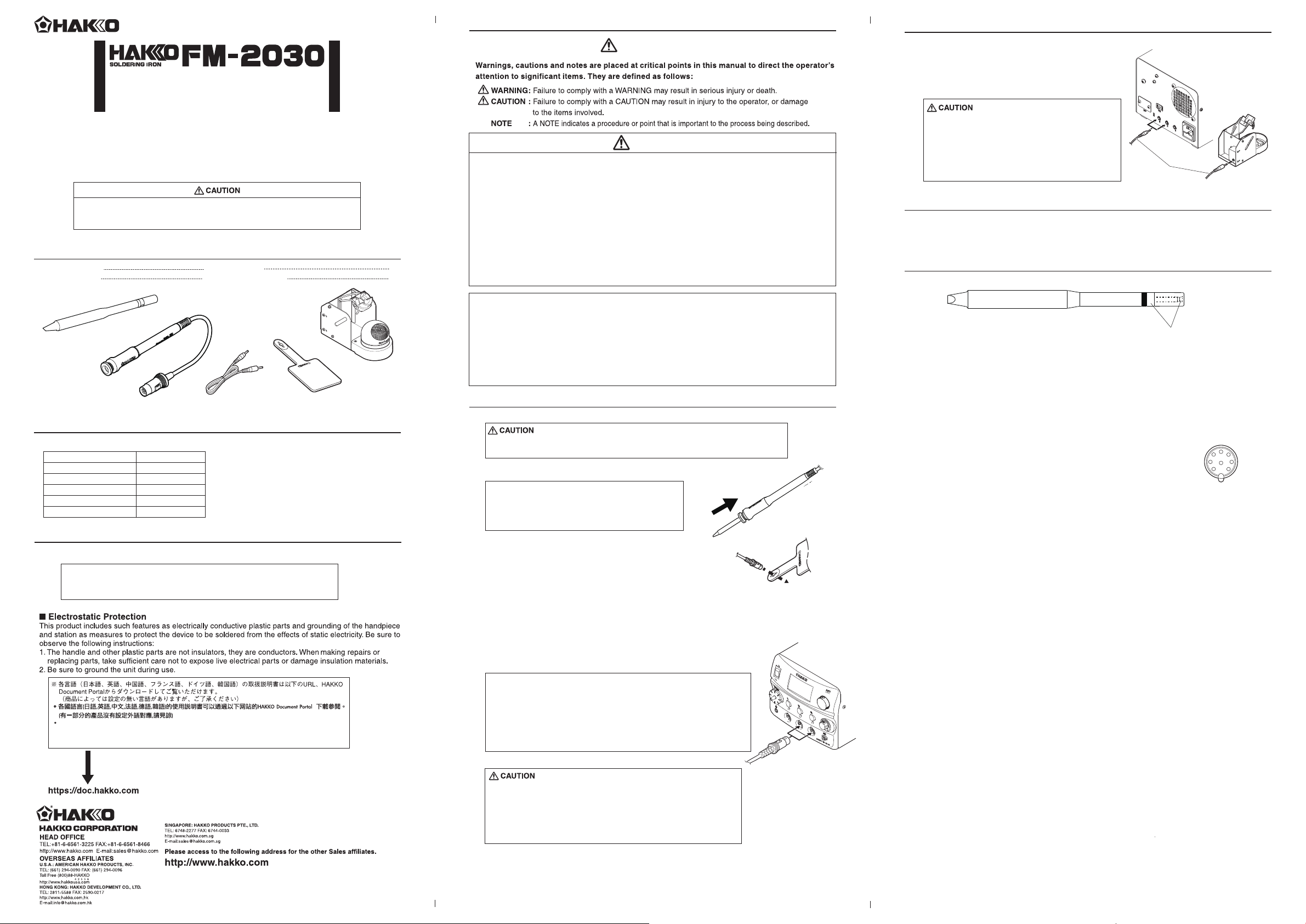
1. PACKING LIST AND PART NAMES
HAKKO FM-2030
Heat resistant pad
Tip (not included)
HAKKO FM-2030
Iron holder
1
Connecting cable
1
Connecting cable Heat resistant pad
2. SPECIFICATIONS
●HAKKO FM-2030
Power Consumption
Tip to Ground Resistance
Tip to Ground Potential
Length of cord
Length (w/o cord)
Weight (w/o cord)
140W (24V)
< 2 Ω
< 2 mV
1.3 m (4.3 ft)
155 mm (6.1 in.)
32 g (0.07 lb.)
*Specifications and design are subject to
change without notice.
*This product is protected
against electrostatic discharge.
3. COMPATIBLE STATIONS
Use the HAKKO FM-2030 with the HAKKO FM-206 station or the HAKKO FM-203 station.
NOTE :
That use with the HAKKO FM-203 station may require a station upgrade.
Contact your HAKKO factory representative for more information.
Please check to make sure that all items
listed below are included in the package.
Iron holder
WARNING
●Use of the sleep function
When using the sleep function, insert one
end of the connecting cable into the jack at the
back of the handpiece holder and the other end
into the jack at the back of the station to connect them.
• Please make sure the power is off
when you plug in cables.
CAUTION
When power is ON, tip temperature will be between 200℃ and 500℃ (400 to 930℉).
To avoid injury or damage to personnel and items in the work area, observe the following :
Do not touch the tip or the metal parts near the tip.
●
Do not allow the tip to come close to, or touch, flammable materials.
●
Inform others in the area that the unit is hot and should not be touched.
●
Turn the power off when not in use, or left unattended.
●
Turn the power off when changing parts or storing the HAKKO FM-2030.
●
This appliance is not intended for use by persons (including children) with reduced physical,
●
sensory or mental capabilities, or lack of experience and knowledge, unless they have been
given supervision or instruction concerning use of the appliance by a person responsible
1
1
for their safety.
Children should be supervised to ensure that they do not play with the appliance.
●
●
Do not use the HAKKO FM-2030 for applications other than soldering.
●
Do not strike the iron against hard objects to remove excess solder. This will damage the iron.
●
Do not modify the unit.
●
Use only genuine HAKKO replacement parts.
●
Do not allow the HAKKO FM-2030 to become wet, or use it when hands are wet.
●
Be sure to hold the plug when inserting or removing the iron cord.
●
Since smoke is produced when using the HAKKO FM-2030, be sure the work area is well ventilated.
●
While using the HAKKO FM-2030, do not do anything which may cause bodily harm or physical damage.
5.INITIALSETUP
●Connection
• Please make sure to hook up the
connector cable and the iron holder on the
same channel and not to place the iron in a
holder connected to a differing channel.
6. OPERATION
For operation, please refer to the appropriate sections
of the HAKKO FM-203/HAKKO FM-206 User Manual.
7. CHECKING PROCEDURE
Measure the resistance across these positions.
1. Check for a broken heater
Check the heating element for electric fault.
Measure the heater element at room temperature
(15 to 25°C; 59 to 77°F).
Normal resistance value is 4Ω ±10%. If resistance value is
Connecting cable
abnormal, replace the tip with a new one.
The tip may be hot. Avoid holding the hot tip for a long time even if
using the heat resistant pad. Otherwise burns may result.
A. Insert the tip
Insert the tip into the HAKKO FM-2030 until it stops. (Fig.1)
NOTE :
2. Check the grounding line.
If the resistance value is higher than 2Ω (at room temperature),
remove the black oxide or replace the tip with a new one.
If the resistance value still does not decrease, check the
connection cord for breakage.
2
5
4
3
7
1
8
6
Please use only T22 Series Tips.
The attempted use of other tips may damage
the product and/or station.
B. Soldering iron
(Fig.1)
3. Checking the connection cord for breakage.
Measure the resistance between the connector pins.
Between pin 1 and pin 3: 3.6 to 4.4Ω.
If the resistance value is different from the above values,
replace the HAKKO FM-2030.
Pass the iron cord through the hole in the heat resistant pad.(Fig.2)
C. Station
(Fig.2)
• If used in conjunction with HAKKO FM-203
Connect the cord assembly of the HAKKO FM-2030 to
channel D connector of HAKKO FM-203.
• If used in conjunction with HAKKO FM-206
Connect the cord assembly of the HAKKO FM-2030 to
channel 2 or channel 3 connector of HAKKO FM-206.
Instruction manual in the language of Japanese, English, Chinse, French, German and Korean
can be downloaded from the HAKKO Document Portal.
(Please note that some languages may not be available depending on the product.)
Copyright © 2011 HAKKO Corporation. All Rights Reserved.
MA02387XZ110525
2011.5
NOTE :
The HAKKO FM-203 has 2 channels ; D and S channel.
The HAKKO FM-2030 can be connected to only the D channel.
The HAKKO FM-206 has 3 channels ; 1, 2 and 3 channel.
The HAKKO FM-2030 can be connected to channel 2 or 3.
Refer to the HAKKO FM-203/FM-206 instruction manual
for details of operation.
When connecting or disconnecting the
・
cord assembly, hold the plug.
Be sure to turn off the power switch before connecting or
・
disconnecting the cord assembly for the handpiece to
and from the receptacle to avoid damaging the unit.
Page 2
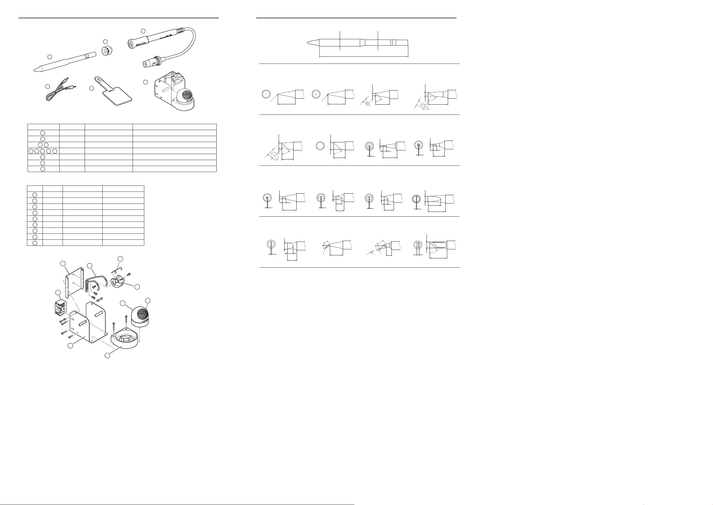
8. PARTS LIST
9.TIPSTYLES
1
4
●HAKKOFM-2030
Item No.
1
2
2 3
2 3 4
4
5
6
5
B3687
FM2030-01
6
FM2030-02
B3253
B2300
FH200-01
●IronHolder
Item No.
Part No. Part Name Specifications
1
B3001
2
B2791
3
B3248
4
B3251
5
B3249
6
B3250
7
B3252
8
599B-02
9
599-029
2
5
Part No. Part Name
Tip
Nipple
HAKKO FM-2030
HAKKO FM-2030
Connecting cable
Heat resistant pad
Iron holder
Iron receptacle
Retaining clip
Holder for iron receptacle
Iron holder base
Cleaner base
Stay
Switch case assembly
Tip cleaner
Cleaning wire
6
With screws
With rubber foot
With rubber foot
3
3
6
See “TIP STYLES”
With O-ring
24V-140W
24V-140W Conversion kit
2
Specifications
(0.28)
φ7.2
T22-BL SHAPE-BL T22-BL2 SHAPE-2BL
R0.2
(R0.008)
15
(0.60)
R0.5
(R0.02)
15
(0.60)
T22-C5 SHAPE-5C T22-C6 SHAPE-6C
(0.20)
φ5
5.3
45˚
(0.21)
10
(0.39)
T22-D16 SHAPE-1.6D
(0.06)
φ1.6
3
(0.12)
(0.02)
0.5
12
(0.47)
φ6 (0.24)
45˚
10
(0.39)
T22-D24 SHAPE-2.4D
φ2.4 (0.09)
5
0.5
(0.20)
(0.02)
(0.28)
7
(0.22)
φ5.5
87
(3.43)
Unit : mm (in.)
T22-C3 SHAPE-3CT22-BC2 SHAPE-2BC
2.3
(0.09)
(0.08)
φ2
45˚
12
(0.47)
3.7
(0.15)
(0.12)
φ3
60˚
17
(0.67)
T22-D08 SHAPE-0.8D T22-D12 SHAPE-1.2D
(0.02)
(0.03)
φ0.8
3
(0.12)
0.5
12
(0.47)
(0.02)
φ1.2 (0.05)
3
(0.12)
0.5
10
(0.39)
T22-D32 SHAPE-3.2D T22-D45 SHAPE-4.5D
(0.02)
(0.13)
φ3.2
3
(0.12)
0.5
8
(0.32)
(0.02)
(0.18)
φ4.5
11
(0.43)
0.5
15
(0.59)
T22-D52 SHAPE-5.2D T22-J02 SHAPE-0.2J T22-JD08 SHAPE-0.8JD T22-K SHAPE-K
(0.03)
(0.21)
φ5.2
5
0.7
(0.20)
8
(0.32)
4
30˚
R0.2
(R0.008)
(0.16)
11
(0.43)
φ0.8
(0.03)
6.3
30˚
(0.012)
(0.25)
0.3
4.5
(0.18)
(0.08)
(0.20)
φ5
45˚
2
15
(0.60)
7
1
8
9
4
5
 Loading...