

Page 1

Page 2

TABLE OF CONTENTS
Introduction
.....................................................
Page
1
Features ..........................................................
Page
1
Installation and Setup..
....................................
Page 2
Special System Configurations
.......................
Page 4
Rear Panel ......................................................
Page8
Operation ........................................................
Page 9
LED Displays ...................................................
Page 9
Care ................................................................
Page
10
Troubleshooting
..............................................
Page
10
Specifications
..................................................
Page
12
Warranty
. . . . . . . . . . . . . . . . . . . . . . . . . . . . . . . . . . . . . . . . . . . . . . . . . . . . . . . . . .
Page 13
Page 3

INTRODUCTION
The JF2000 is the first amplifier in the signature series line
of Hafler audio components. In the Hafler tradition, it is hand-
made in America. The signature series embodies Hafler's
philosophy of supplying the same quality music reproduc-
tion of higher priced audio components for less.
FEATURES
Output Section
High Current
Capability
Wide Load
Range
SOA Protection
(Safe
Operating
Area)
Thermal
Protection
The
JF2000
uses 32 MOSFET output devices - 16 per
channel - to source the high current and power required.
Each device is rated at 4.0 Amperes continuous drain
current at 100 degrees Celsius.
Each channel can safely produce peak transient output
currents exceeding 50 Amperes. This ensures that mo-
mentary speaker impedance dips and surge current requirements are easily supplied.
The JF2000 is fully rated for loads of 4 and 8 Ohms. It is
stable to 2 Ohms. (This means it will operate safely, cleanly
and stably into 2 Ohms, but very high power dissipation may
lead to frequent thermal shutdown.)
The 16 output devices per channel assure operation well
within the MOSFET Safe Operating Area with low imped-
ances and/or reactive loads.
The output devices of the JF2000 are protected by a so-
phisticated analog computing system. The device instantaneous temperature is continuously calculated by the com-
puter and compared to a maximum limit. If the limit is
reached, the computer cuts back thte power and lights the
channel’s distortion (red) front panel LED.
A pair of thermistors, one mounted on each heatsink, measure temperature of the output system. They control fan
speed and provide thermal shutdown in case temperatures
become too high for safe operation. (Thermal shutdown
turns the power lamp red.)
Page 4

Toroidal
Transformer
Energy Storage
Great Flexibility
Display
Fan Cooling
The fan cooling system is a key to the
JF2000’s
perfor-
mance. The fan is of a very quiet design, with continuous
variable speed control. When the amp is cool, the fan is
off
As the amp is driven harder, the fan gradually turns on and
speeds up only to the extent needed to sustain the power
dissipation needed for the conditions.
The power supply for the JF2000 is based on a 1000 Volt-
Ampere toroidal (donut-shaped) line transformer. We use
the toroid core (which is more expensive than a conventional
square transformer) for its higher efficiency, lower weight,
smaller size, and freedom from stray magnetic fields. The
1000 Volt-Ampere rating indicates that the transformer can
supply power to a load of 1000 Watts continuously.
Energy storage for the power supply consists of two 42,000
Microfarad capacitors. This large energy storage capability
provides a low-impedance source of extremely high current
for surges, musical transients, variations in speaker impedance, and very low frequencies.
Individual channel gain controls match the JF2000 to a wide
range of installations.
Four Output Modes are available to fit almost any require-
ment: Normal Stereo, Stereo plus Bridged Mono, Bridged
Mono, and Dual Mono.
Simple three-LED multicolor display shows amplifier status
including power, signal level, distortion, and thermal condi-
tion.
INSTALLATION AND SETUP
Amplifier
Placement
The JF2000 is designed to be placed on a shelf or other
substantial support. (A rack-mount front panel is available.)
Take care to ensure unimpeded airflow behind the amplifier,
as the intake and exhaust vents are located at the rear. If the
amp is to be placed in an enclosed wall unit or cabinet, it
would be a good idea to allow for fresh air intake and hot air
exhaust venting in the back of the cabinet, especially for
continuous high-output operation.
2
Page 5
Power
Connection
Speaker
Connection
Normal Stereo
Connections
The
JF2000 is designed to operate on 120 Volts AC, 60 Hertz
standard U.S. line output) only. Connection is via a standard
3-prong grounded AC plug. If a
3-prong (grounded) outlet is
rot available, the third (ground) wire MUST be grounded to
a
satisfactory electrical ground using adapters available at
nost hardware stores.
If an extension cord must be used, it will rob power from the
amplifier. Use only the highest qualtiy 3-wire (grounded)
extension
cords, with large wire
(14-Gauge
or larger) to
educe
losses.
Speaker
connectors are heavy-duty
gold-plated “5-way”
binding posts, spaced for standard banana jack connectors.
They will accept bare stranded wire up to approximately
12-
Gauge. Banana connectors may be more convenient.
For
normal stereo operation leave ALL REAR PANEL
SWITCHES IN. The amplifier’s left channel red binding post
connects to the left positive (+) speaker terminal and the left
black
post goes to the left negative (-) speaker terminal. Wire
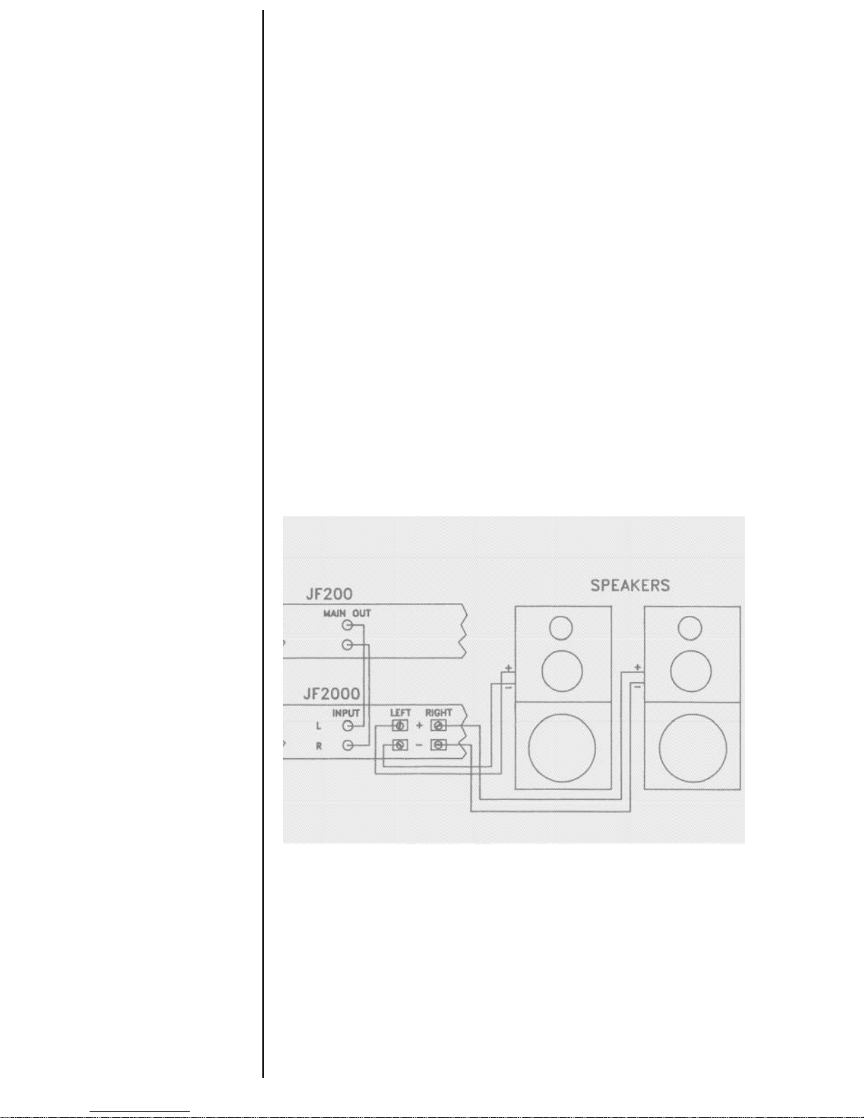
the right channel the same. (Refer to Figure 1)
Figure 1
Left
positive (+) terminal (red) to Left Speaker positive (+)
Left
negative (-) terminal (black) to Left Speaker negative (-)
Right
positive (+) terminal (red) to Right Speaker positive (+)
Right
negative (-) terminal
(black) to Right Speaker negative (-)
3
Page 6

Speaker
Polarity Note
Be sure to observe speaker polarity (+ and - leads) through-
out your system. Getting them wrong can result in missing
bass, massive distortion, or blown speakers!
SPECIAL SYSTEM CONFIGURATIONS
Biamplification
Dual Monaural
(Mona)
What
‘PLEASE NOTE:
The minimum nominal load impedance for
each
channel of the amplifier is 4 ohms. In bridged mode,
each
channel of the amplifier uses half of the nominal load
impedance. Therefore, in bridged/mono mode the minimum
equired load impedance is 8 ohms.
If the speaker system in use is capable of having separate
inputs for the woofer and midrange or tweeters, or if the
system
has a woofer in a separate box and satellite midrange
and
tweeters, then the final sound from the system could be
improved by biamplifying. This means using two amplifers in
normal
stereo mode, each being driven by a dedicated signal
high or low frequency
-
and loaded by a dedicated driver
-
high
or low frequency. This allows different power levels to
be
applied to the high and low frequency drivers of a speaker
system.
(Refer to Figure 2 for proper hook-up.)
Figure 2
Both
channels are driven by the same signal. (In the JF-
!
2000,
the common signal input is the Left channel input.) In
his mode, both amplifiers are controlled by the left input gain
control
and put out exactly the same kind of signal and
power.
4
Page 7

Why
How
Bridged Mono
What is Bridging?
may wish to drive biamplified pairs of speakers with
identical signals if the speakers have internal crossovers.
‘You may wish to drive multiple speakers which would be too
low in impedance if driven together (under 4 Ohms).
Set the INPUT switch to MONO (out). This feeds the right
and left channel power amplifier section from the left input
signal jack. Connect the speakers the same as you would for
standard stereo. Leave all other switches in the standard
position (IN) unless you have other reasons for using them.
(Refer to Figure 3)
Figure 3
Left positive (+) terminal (red) to Left Speaker
positive (+)
Left
negative (-) terminal (black) to Left Speaker negative (-)
Right
positive (+) terminal (red) to Right Speaker positive (+)
Right
negative (-) terminal (black) to Right Speaker negative
(-)
“Bridging” an amplifier means using two amplifier channels
to drive a single speaker. Normally, one terminal of the
speaker is driven by an amplifier section, and the other
terminal is grounded (that is, current is returned to the driving
amplifier). When a speaker load is driven by a bridged
amplifier pair, each terminal of the speaker is driven by a
separate amplifier section.
5
Page 8

Bridging applies much more power to the speaker load than
either amplifier channel would alone. For an 8-Ohm speaker,
the JF2000
is rated for a minimum output of 200 Watts for a
single channel. For both channels bridged into the same
speaker,
the minimum output would be 600 Watts.
When the application calls for higher power levels than you
can get from the
JF2000 in normal stereo, you can use the
bridged mono mode.
USE CAUTION! Most speakers cannot handle the power of
the JF2000 in bridged mono mode.
Typical applications include: driving large (mono) subwoofers,
large power hungry speaker systems, or bi-amp applications
where large amounts of power are required.
In order to use both channels of input to sum the signal to
drive a mono speaker, set the input switch to stereo (IN) and
the output switch to mono (OUT). The amplifier’s left channel
red binding post connect to the positive (+) speaker terminal
and the right channel red binding post connects to the
negative (-) speaker terminal. (Refer to Figure 4)
I
Figure 4
6
Page 9

Bridged Mona
Stereo Plus Stereo satellites can be driven at the same time as a bridged
mono subwoofer or bridged center channel speaker (with
one
JF2000).
If you have satellites designed specifically for midrange and
treble, with a single mono subwoofer designed for bassonly:
Set output switch to MONO (OUT). All other switches IN.
This inverts the right channel output, while leaving the input
stereo. You will connect the left speaker normally, but the
right speaker POS (+) and NEG (-) will be REVERSED from
normal stereo. The center (bridged mono) channel will be
connected between the two RED (MONO) amplifier termi-
nals. (Refer to Fig. 5)
Figure 5
Left Positive (+) terminal (red) to Left Speaker Positive (+)
Left Negative (-) terminal (black) to Left Speaker Negative (-)
Right Negative (-) terminal (black) to Right Speaker Positive (+)
Right Positive (+) terminal (red) to Right Speaker Negative (-)
Left Positive (+) terminal (red) to Mono Speaker Positive (+)
Right Positive (+) terminal (red) to Mono Speaker Negative (-)
7
Page 10

REAR PANEL
Switches
Balanced/
Unbalanced Input
Switch
Home Version
Input Switch
(Right Channel)
Output Switch
(Right Channel)
Ground Switch
Input
Connections
Level Adjust
Speaker Fuses
NOTE:
Normal stereo position for all rear panel switches is
IN. The only time any of the switches should be OUT is for
one of the special functions in this section.
Be sure to turn the amplifier OFF before changing rear panel
switch positions (to avoid possible pops and clicks).
The Balanced/Unbalanced Input Switch is disabled in the
JF2000. This function is used only with special professional
connectors (XLR and
1/4
inch phone plugs) available with
the PRO6000 professional back panel.
IN position: Stereo. Right input feeds Right channel.
OUT position: Mono. Left input feeds Right channel.
IN position: Stereo (normal). Right channnel is in phase with
Left.
OUT position: Mono. Right channel is reversed in phase
compared to Left.
IN position: Floating (normal). Chassis ground separate
from Output section ground.
OUT position: Chassis. Chassis ground connected to output
section ground.
This switch should be set for minimum system hum.
Input is via standard “RCA” style pin jacks.
Input sensitivity is adjustable with the level controls adjacent
to each input RCA jack. The overall gain ranges form zero
(fully counter-clockwise) to 36 dB (fully clockwise).
The JF2000 is equipped with AGC5-Ampere speaker pro-
tection fuses. These fuses are for speaker protection only.
Most speakers will not handle more than a 5-Ampere fuse (or
less). Refer to your speaker manufacturer’s recommendations for your fuse selection.
Page 11

OPERATION
Turning On
The Amp
First Time: Before turning on the power switch to the JF2000
forthefirst time, double-check all speaker and input connections and turn the input level controls all the way down (fully
counter-clockwise). Turn on your source equipment (preamp, CD player, etc.) Turn the power switch on and adjust
the input controls so that the left and right channel LEDs light
up green at a low preamp volume control position.
Normal Operation: As with any high-powered amplifier, it is
b
est to turn on the amplifier AFTER all other equipment is on,
and turn it off BEFORE any other equipement. This prevents
any turn-on or turn-off transients from other equipment
damaging your speakers.
LED DISPLAYS
Channel
Status
LEDs
From left to right the front panel LEDs indicate: Left Channel
Status, Right Channel Status, and Power Status.
The Channel Status LEDs indicate the condition of the Left
and Right channel outputs. They will turn on GREEN to
indicate a signal output of over about 200 Milliwatts. They will
switch to RED to indicate distortion over about 0.5% THD.
The Power Status LED will turn on GREEN to indicate power
on. In case of overheating, it will switch to RED and the
amplifier will turn off until it cools down.
The channel status LEDs can show three indications:
OFF indicates no signal or a signal level under about 200
Milliwatts (a very quiet level with most speakers).
GREEN indicates a signal over about 200 Milliwatts and very
low distortion (under 0.5% for most conditions); that is,
normal operation.
RED indicates distortion in the output signal for any reason:
blown speaker fuse, shorted speakers, excessive speaker
load, or any other reason.
Page 12

Power
Status
The Power Status LED can show three indications:
LEDs
OFF: The power switch is off, the amplifier is not plugged in,
or the main fuse is blown.
GREEN: Indicates normal power and operation.
RED: Indicates amplifier overheat. Leave the switch on and
the fan will cool the amplifier down to operating temperature
very quickly.
CARE
Do not allow speaker wires to touch each other, chassis
ground, or any metal object.
Protect your amplifier from moisture and dust.
Clean anodized finishes with soft, damp cloth.
Save the original carton and packing. It is the only safe way
to ship the amplifier. If you need to replace the carton and/or
packing, consult your authorized dealer or Hafler Customer
Service Department.
No user serviceable parts inside. Do not disassemble amplifier for any reason. Refer to an authorized Hafler warranty
station or to Hafler directly. See Warranty Statement.
TROUBLESHOOTING
LED Displays for
The LED displays show a lot of information about how the
Troubleshooting
amplifier is acting. They can provide direction and trouble-
shooting information for most system problems if they are
interpreted properly.
Power Status LED
The Power LED can show three indications:
(Rightmost LED)
OFF: No power is reaching the main amplifier board lowvoltage section.
GREEN: Normal low-voltage power is available.
RED: Amplifier has shut down due to overheating (fan will
still run to cool the amplifier).
10
Page 13

No LED
Turns Red
(overheats)
Rapidly
Channel Status
LEDs
(Two Left
LEDs)
This is an indication that no power is reaching the amplifier.
Possible reasons include:
1) Amplifier not securely plugged in.
2) Power source (socket) failed (AC line fuse blown,
wiring open, etc.)
3) Internal amplifier fuse blown. Fuse replacement
should only be attempted by a qualified technician.
1) Rear cooling channels blocked. Clear the area behind
the amp.
2) No fresh air ventilation (rear air intake and output feeding
each other). Provide a source of fresh air (not heated air)
for the inlets at the sides.
3) Excessive loading. If the amplifier is run into less than a
4-Ohm speaker load per channel, or is bridged into less
than 8-Ohms, the amplifier may not be able to produce
continuous high output levels without overheating. Reduce the loading by increasing load impedance.
4) Fan is jammed or has failed. Clear the obstruction or
replace the fan.
5) There may have been an internal malfunction. Send amp
to the factory or a qualified technician for repair.
The channel status LEDs can show three indications:
OFF indicates no signal or a signal level under about 200
Milliwatts (a very quiet level with most speakers).
GREEN indicates a signal over about 200 Milliwatts and very
low distortion (under 0.5%) for most conditions); that is,
normal operation.
RED indicates distortion in the output amplifier sectionforany
reason: blown speaker fuse, shorted speakers, excessive
speaker load, or any other reason.
11
Page 14

SPECIFICATIONS
8-Ohm
POWER: Over 200 Watts per channel from 20 Hertz to
Performance
20,000 Hertz, both channels driven, at rated distortion.
4-Ohm
POWER: Over 300 Watts per channel from 20 Hertz to
Performance
20,000 Hertz, both channels driven, at rated distortion.
2-Ohm
Performance
S/N Ratio:
Peak Output
Current:
Frequency
Response:
Power Bandwidth:
Protection:
DISTORTION: Less than 0.05% Total Harmonic Distortion
plus Noise, 20 Hz to 20,000 Hz, both channels driven at full
power.
IM DISTORTION (IHF): Less than 0.01%
SLEW RATE: Exceeds 80 Volts per Microsecond.
DISTORTION: Less than 0.10% Total Harmonic Distortion
plus Noise, 20 Hz to 20,000 Hz, both channels driven at full
power.
IM DISTORTION (IHF): Less than 0.02%
Stable into two Ohms.
May overheat and shut down rapidy if driven hard at 2 Ohms.
Over 110 dB (unweighted) with respect to full power.
50 Amperes
20
Hz to 20,000 Hz: +0.l, -0.25 dB
5
Hz to 75,000 Hz: +0.l, -3.0 dB
5 Hz to 75,000 Hz
Capable of safe operation indefinitely into any load condi-
tion.
Sustained (over 1 second) hard clipping at ultrasonic fre-
quencies (over 20 KHz) will cause protection to activate, the
limit peak power. Please test ultrasonic behavior either with
signals that don’t cause clipping or with tone bursts.
12
Page 15

FACTORY SERVICE AND LIMITED WARRANTY
If you encounter any diff iculty or have any questions concern-
ing your
JF2000
preamplifier, please call our Customer
Service department weekdays, 8:00 am to 3:30 pm Mountain
Standard time, at 602-967-3565.
Before returning any unit to the factory for service, please call
us. All units being returned (regardless of warranty status)
must receive a Return Authorization (RA) Number. In addi-
tion, we can offer trouble-shooting assistance that may often
simplify or even eliminate the need for factory service.
The Hafler JF2000 is warranted for 3 years from date of
purchase, including parts, labor, and return shipping costs
from the factory to the owner within the Continental U.S.A.
It is the owner’s responsibility to pay shipping (preferably
UPS) to the factory: collect shipments will not be accepted.
Units under warranty should be accompanied by a copy of a
dated Bill of Sale. Use the original carton and all packing
material, and be sure to include a return address, and a brief
description of thedifficulty, including whether it is intermittent.
This warranty gives you specific legal rights. You may also
have other rights which vary from state to state.
13
Page 16

Hafler
A Division of Rockford Corporation
613 South Rockford Drive
Tempe, Arizona 85281 U.S.A.
602
-
967 - 3565
 Loading...