

THE
POWER
AMPLIFIER
DH-200
INSTRUCTIONS
for
ASSEMBLY
and OPERATION
929204
$3.00
THE
DAVID
HAFLER COMPANY
5910 Crescent Boulevard, Pennsauken,
New
Jersey 08109
Please
refer to this serial
number in all communications
regarding this equipment.
INTRODUCTION
The
Hafler
DH-200 is a two channel audio power amplifier
designed to the very
highest
performance standards. It is
available either as a kit, or fully assembled. Its 100
watt
per
channel power rating is sufficient for
driving
all
loudspeakers in home applications, and its design provides
extremely low distortion of
all
types. A combination of high
performance,
dependability and reliability, and moderate
price
is in the
Hafler
tradition of using the
latest
technology
to provide outstanding value.
Combining
the
latest
power
MOSFET
technology with
uniquely
simple
and
effective
circuit
topology reduces distor-
tion of all types, and at all power
levels,
over the
full
audio
frequency spectrum, to the vanishing point. In addition to its
pace-setting performance achievements, the conservative
mode of operation accomplishes a new high in long term
reliability
and exceptional resistance to abusive operating
conditions.
This
is one of the direct
benefits
of
MOSFET
utilization
in overcoming a serious limitation of conven-
tional
transistors — their tendency to self-destruct under
other than normal operating conditions. So rugged is the
DH-200
that it can deliver as much as ten amperes into a
short circuit!
The
speed — measured as the
slew
rate — of this design
delivers unmatched transient linearity, revealing the most
delicate shadings,
textures
and nuances of the music, surpass-
ing
the capabilities of the most revealing loudspeakers and
cartridges by a wide margin. Coupled with its unconditional
stability, and ability to deliver adequate power into any
loudspeaker load, the result is absolute freedom from listen-
ing
fatigue. The longer you listen to this phenomenal
amplifier,
the more certain you will be that you could not
have made a better choice.
Though
modest in
cost,
the DH-200
evidences
the very
finest electrical and mechanical design. It avoids costly frills
and
unnecessary gadgetry while
providing
quality sound and
reliability
based on top grade components conservatively
operated.
The
oversized power transformer
and
bridge rectifier; the
massive
heat
sinks; the conservative operating
levels
of the
MOSFET
output
devices
— all are evidence of the design
efforts to achieve exceptional reliability simultaneously with
state
of the art
sonics
and specifications. And this circuit is
convertible (with an internal accessory bridging circuit
board)
to a high power monophonic amplifier with
equivalent stability and specifications.
The
fully complementary, symmetrical push-pull circuit,
which
is direct coupled throughout
(except
at the input), in-
corporates all silicon
devices
in a format which is directly
related to the highly acclaimed DH-101 preamplifier. Its
unique self-protecting output
stage
prevents the thermal
runaway
which is a common threat to solid
state
amplifiers.
The
ruggedness and conservative operation of the output
stage
allows the DH-200 to avoid the need for special protec-
tive circuits which could compromise audio performance.
Basic
protective
systems
provide maximum security against
malfunction
damage to the amplifier or the speaker: the AC
line fuse, B+
fuses,
thermal breakers,
and
loudspeaker
fuses.
Nothing
hinders the essential purity of the audio signal.
Those who use
these
instructions to
assemble
the
DH-200
kit will
find
that the
left
and right audio modules
(printed
circuit and
heat
sink
assemblies)
are preassembled
and
pretested.
This
greatly simplifies the kit assembly so that
it can be done in only a few hours without special skills or
know-how. Because of the modular arrangement, it is possi-
ble to operate on one channel if the other requires service,
and
obviates the need to return the entire amplifier in
cases
where one channel is inoperative.
Accessories for special applications include the input
bridging
circuit board for monophonic use; a panel for stan-
dard
19"
rack
mounting; and an alternative power
transformer
for international AC line
voltages.
Through
advanced engineering geared to the audio per-
fectionist, and an efficient no-frills approach,
Hafler
is mak-
ing
high technology high fidelity affordable.
CONTENTS
Operation
Page
3 AC
Line
Connections
for
Overseas
Use 12
Assembly
Instructions
4 Kit
Parts
List
13
Wiring
the Kit 6
Schematic
Diagram
14
If
Problems
Arise
10
Component
Value
Listing
15
Service
and
Warranty
11
Pictorial
Diagram
Insert
©
Copyright
1980.
All
rights
reserved.
2
INSTALLATION
The
DH-200 is most likely to be ihstalled out of sight in
most applications, since its power may be controlled by the
AC
switching of most audio preamplifiers, like the
Hafler
DH-101.
If your control unit
does
not provide switching
capacity sufficient for the amplifier's 5 amp
needs
(plus other
equipment it is
also
switching), you should use the amplifier's
own power switch. In that
case,
turn
on the preamplifier first;
then
turn
the amplifier on a few
seconds
after
the preamp has
been turned on, to avoid any unnecessary turn-on transients
from
some
preamplifiers. Likewise, switch the power
amplifier
off first.
If
the amplifier is to be installed
close
to a record player,
you
should first check its position for freedom from hum
pickup
by the cartridge from the field radiated by the power
transformer
of the DH-200. Although the design of the
transformer
minimizes such radiation, certain cartridges are
more
sensitive
than others, and require separation from the
amplifier.
Check
at a comparatively high volume setting, and
while swinging the
tone
arm throughout its arc. Often a few
inches additional spacing will eliminate the problem.
Be
sure to provide sufficient
ventilation
for the amplifier.
Unobstructed
air
circulation
around the finned
heat
sinks
and
above
the amplifier is important for long, trouble-free
life. Never put anything on top of the cover perforations. It is
normal
for the top and the
heat
sinks to become warm in use.
It is expected that the amplifier will always be resting on
its
feet,
which should be on a
hard
enough surface that air
flow underneath is not obstructed. If it is mounted in a rack,
or
through a panel, the
feet
may be removed so long as ade-
quate ventilation is provided through the bottom openings.
OPERATION
The
red pilot lamp which is integral with the power
switch
glows
whenever the amplifier is turned on. A blown
AC
line
fuse
is the most likely
cause
if it is not illuminated
when the amplifier is switched on.
The
yellow
lens
is a high temperature indicator. While it
is not likely that you will ever see it lighted, if it is, the
amplifier
will not produce sound. It indicates that one of the
thermal
breakers has shut down the amplifier
because
of ex-
cessive
temperature rise in a
heat
sink.
When
the
heat
has dis-
sipated in a few minutes, the amplifier should return to nor-
mal
operation. If the lamp again lights, check for insufficient
ventilation, or an
excessive
input signal, or an input which
may have dangerous signal content (such as oscillation).
Failing
evidence of this, the amplifier may have malfunc-
tioned. Because of the very large
heat
sinks, it is highly
unlikely
that any normal signal will
cause
the amplifier to
overheat.
Loudspeaker
Fuse Selection
The
DH-200 power amplifier is supplied with 2 amp
fuses
in the speaker lines. Experience has shown that since an
overload
must
exist
for a few
seconds
for a
fuse
to blow, a 2
amp
fuse
will protect most speaker
systems,
and only blow
when overload occurs. Smaller
fuses
tend to blow too easily,
and
larger
fuses
do not adequately protect most speaker
systems.
A
pair
of 5 amp
fuses
are
also
supplied as alternatives for
the speaker
fuse
holders. These should be substituted if the
power output of the amplifier is to be
tested,
or if the
amplifier
is to be operated at very high power
levels
into 4
ohm
loads.
If
the manufacturer of your speakers recommends a
specific value of
fuse
for their protection, we
suggest
that you
obtain 3AG
fuses
of that value and substitute them for the
ones
supplied.
Loudspeaker
Power Ratings
There
are no U.S. standards for rating the power han-
dling
capabilities of loudspeakers. As a result the manufac-
turers'
usual "music power" ratings, or
suggested
amplifier
limits,
are of only
minimal
help in determining
safe
operating
levels
with amplifiers which can deliver substantial amounts
of
power. You must take into consideration the type of
music, and the
levels
you like, to provide long term trouble-
free operation of
your
speaker choice, when you have a
size-
able amplifier like the DH-200.
Connections
AC
The AC
power cord should be plugged into 120 volts, 60
Hz,
on the switched output of a preamplifier which can
pro-
vide at
least
5 amps, or 600
watts.
Then
the amplifier power
switch may be
left
on, and it will be controlled by the rest of
the system.
Or,
it may be plugged into a 120 volt wall outlet,
and
switched on and off independently.
If
your line voltage is different, be sure you have the
alternate power transformer which can accommodate several
line
voltages,
and be sure it is
wired
for
your
mains voltage as
described later in this manual
before
you
plug
in the
amplifier.
Input
Conventional
shielded cables, such as
those
supplied
with your preamplifier, provide the input signal to the
sockets
on the back panel of the DH-200. Be sure that the
outer shield connection is secure, to avoid hum. The length
of
these
cables (so as to permit remote location of the
amplifier,
if desired) is limited only by the output impedance
of
the preamplifier. If it is 1,000 ohms or
less,
as with the
DH-101,
for instance, cable
lengths
up to 100
feet
are per-
missible without
loss
of performance. Special low .maci-
3
tance cables enable
even
greater distance
between
preanip
and
amplifier. It is desirable to keep the
left
and right input
cables
close
together
throughout their length to minimize the
likelihood
of hum pickup.
Also,
you should avoid running
them parallel to
AC
cords —
these
should be crossed at right
angles.
Output
The
loudspeakers (or headphones) connect to the red
and
black terminals in the center of the back panel. These
binding
posts
provide several convenient alternative con-
necting methods. The screw cap may clamp the bared wire
end,
or a "spade lug" attached to it, but a better connection
will
be made by locating the hole
drilled
through the shaft of
the terminal when the cap is unscrewed. Insert the twisted
end of the bared wire so that the cap will clamp it in place.
Always
be sure that no strands of wire are unsecured, and
that the bared end is not too long to
risk
contacting other
ele-
ments. A soldered end or fitting is the
safest
solution.
These terminals
also
accept standard plug-in "banana pin
connectors," including the double
ones
with standard 3/4"
spacing, available from electronic supply
houses.
These are
the most convenient, especially if you may wish to in-
terchange speakers occasionally.
It is important to maintain correct phasing of the
speakers when making their connections. Some speaker ter-
minals are coded red and black, or + and —, etc. It is im-
portant that the
"sense"
of one speaker's connections match
the others. If one is reversed, you will
find
that the sonic im-
age has a "hole in the middle," and that it is deficient in bass.
Speaker wire always identifies one conductor to make this
easy.
There may be a molded ridge in one lead, or the color
of
the insulation on one wire is different, or the wire itself
may be color coded. If pin plugs are used, be sure they are
There
are three basic rules for
success
in electronic kit
building:
1. Read the instructions carefully, and follow them in
order.
2.
Make
secure solder connections which are bright and
smooth.
3.
Check
your work carefully after each
step.
The
DH-200 preamplifier is a versatile component with
sophisticated
circuitry
which has been made
remarkably
easy
to
build
by individuals with many years of experience in the
design and engineering of the finest performing audio kits,
and
in the preparation of their manuals.
Kit
building should be fun, and we are certain you will
find
this to be so. Assembly will be faster, easier, and more
enjoyable if
you
have
someone
help you by reading the
steps
aloud,
selecting the required parts, and
preparing
the
neces-
sary wire
lengths
in advance as you proceed. Fatigue in-
creases
the
risk
of
error,
so take a break rather than push to
early
completion. There are relatively few separate compo-
nents
in this design, to make it
easy
to pack everything away,
if
need be.
color
coded, or that you follow the indexing
mark
on one
side
of the double connectors.
Select
speaker wire of sufficient
size
to preserve the high
damping
factor (and
excellent
speaker control) of your
amplifier.
Standard 18
gauge
lamp cord ("zipcord") is
satisfactory for
distances
up to 30
feet
for an 8 ohm speaker.
As
the distance increases, larger wire
sizes
are recom-
mended. The
next
larger wire
size
is #16, and it is often
preferred
by perfectionists. If you have 4 ohm speakers, the
maximum
cable length for
best
results is halved.
The
black output terminals are electrically connected to
the
chassis
internally. Be certain that when the amplifier is
operated in its normal
stereo
mode that the red output ter-
minals are
never
connected together. In the special
case
when
the amplifier has been internally modified for monophonic
bridged
operation, the output is taken from the two red ter-
minals
only.
Then,
the black terminals are
left
unconnected.
Headphones are normally operated from the loudspeaker
outputs, but are usually connected through a junction box
which
provides switching from phones to speakers. Such a
box usually provides
some
added resistance to reduce the
sensitivity of the phones, and thus minimize the likelihood of
hearing
component noise,
because
of the low setting re-
quired
at the volume control. Some headphone
boxes
utilize
a "common
ground"
system
which makes it
particularly
im-
portant that you carefully observe the proper connections.
While
the black ground terminals
can
be connected together,
the red
ones
must not be.
Some headphones, such as electrostatic types, are
less
sensitive
and may need little or no resistance in
series
for
normal
operation. These could be easily interchanged with
the speakers through the use of double banana plugs.
Your
work area should have good lighting, the proper
toots,
and a place where the large pictorial diagram can be
tacked to the wall within
easy
reach for checking. The
tools
should include:
1. A 40 to 100
watt
soldering
iron
with a 1/4" or smaller
tip which reaches at
least
600°F.
2.
60/40
(60% tin)
ROSIN
CORE
solder, 1/16" diameter
or
smaller.
3. A damp
sponge
or cloth to wipe the hot tip of the
iron.
4. A wire stripping tool for removing insulation.
This
can
be a
single-edge
razor blade, but inexpensive stripping
tools
are safer, faster and easier.
5. A medium-blade screwdriver (about 1/4" wide).
6.
Needle-nose
pliers (a long, narrow tip).
7. Diagonal or side-cutting small pliers.
8.
Large
"gas" or "slip-joint" pliers.
9. A 1/4" "Spin-tite" nut driver may be helpful, but is not
necessary.
4
ASSEMBLY
INSTRUCTIONS
A
soldering "gun" is not recommended. The unfamiliar
user is more likely to damage the etched circuit boards with
its higher
heat
potential and unbalanced weight.
Also,
because
he may not wait long enough for it to reach operat-
ing
temperature each time it is switched on, poor solder con-
nections are more likely. Pencil irons are much lighter and
easier to use, and there is no waiting time when solder con-
nections follow in
sequence,
as in kit building.
Make
sure
you
have a holder for it, though, and always unplug it when
you
take a break.
Proper
Soldering
There
are four
steps
to making a good solder connection:
1.
Make
a good mechanical connection to hold the wire in
position while
heat
and solder is applied.
2. Heat
the junction
of the wire and iug, or
eyelet,
with the
bright,
shiny tip of the
iron.
3.
After
heating for a couple
seconds,
apply solder to the
junction.
It should melt immediately and flow smoothly
around
both surfaces.
4.
Allow
the connection to cool undisturbed.
Remember
that the connection is made by the solder, not
by
mechanically attaching the wire to the terminal. Usually
the wire is looped through the lug and crimped in place, but
some
prefer to just place it through the hole and rely on the
stiffness
of the wire to hold it while soldering. Eyelet connec-
tions, of course, are handled this way.
Good
solder connections are
essential
for trouble-free,
noise-free operation. A good solder joint
does
not require
much
solder
around
the conductors. Never
"butter"
partially
melted solder on
the
joint,
as it is
useless.
A good connection
looks smooth and bright
because
the solder
flows
into every
crevice when the parts are hot enough. The
iron
must have a
bright,
shiny tip to transfer
heat
easily to the
junction.
That's
why the damp
sponge
should be used frequently to wipe the
tip,
and occasionally you must add a small amount of solder
to the tip, too. If a connection is difficult to heat, "wet" the
tip with a small blob of solder to provide a bigger contact
surface to the joint. Once the solder
flows
around the con-
ductors,
any movement must be avoided for a few
seconds
to
allow a good
bond.
When
cool, check the connection by wig-
gling
the wire. If
ir.
doubt, or if the connection is not shiny,
re-heat the
joint.
Excess solder may be removed
from
a con-
nection by heating it and allowing the solder to flow onto the
iron,
which is then wiped on the sponge.
ALL
SOLDER
USED
MUST
BE
ROSIN
CORE.
Never
use acid core solder or any separate flux in
electronic work. Silver solder is
also
not suitable. If
in
doubt
about
unmarked
solder, always obtain a fresh supply of
rosin
core solder. We recommend
60/40
for
easiest
use. Do not
confuse it with
40/60,
which is harder to melt.
The
general procedure is to use a hot
iron
for a short time
to
heat
a connection, then add solder with the
iron
still in
contact. Remove the solder
once
it flows, and then remove
the
iron.
A cooler
iron
applied for a longer time is more
likely
to damage components, or lift the copper circuit pat-
tern
from
the boards. A break in the etched circuit can be
mended by simply soldering a small piece of wire across it.
Do
not allow much build-up of solder on the tip of the
iron,
or
it may
fall
into adjacent
circuitry.
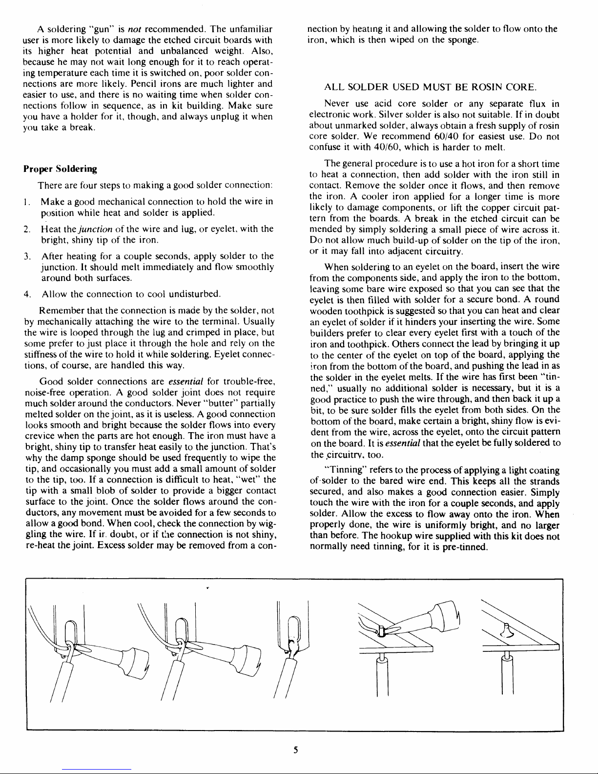
When
soldering to an
eyelet
on the
board,
insert the wire
from
the components side, and apply the
iron
to the bottom,
leaving
some
bare wire exposed so that you can see that the
eyelet
is then filled with solder for a secure bond. A
round
wooden toothpick is
suggested
so that you can
heat
and clear
an
eyelet
of solder if it hinders your inserting the wire. Some
builders
prefer to clear every
eyelet
first with a touch of the
iron
and toothpick.
Others
connect the lead by
bringing
it up
to the center of the
eyelet
on top of the
board,
applying the
iron
from
the bottom of
the
board,
and
pushing the lead in as
the solder in the
eyelet
melts. If the wire has first been
"tin-
ned,"
usually no additional solder is necessary, but it is a
good practice to push the wire
through,
and then back it up a
bit,
to be sure solder fills the
eyelet
from
both
sides.
On the
bottom of the
board,
make certain a
bright,
shiny flow is evi-
dent
from
the wire, across the
eyelet,
onto the circuit pattern
on
the
board.
It is
essential
that the
eyelet
be fully soldered to
the
.circuitry,
too.
"Tinning"
refers to the process of
applying a light coating
of
solder to the bared wire end.
This
keeps
all the strands
secured, and
also
makes a good connection easier. Simply
touch the wire with the
iron
for a couple
seconds,
and apply
solder.
Allow
the
excess
to flow away onto the
iron.
When
properly
done, the wire is uniformly bright, and no larger
than
before. The hookup wire supplied with this kit
does
not
normally
need tinning, for it is pre-tinned.
5
Wiring
the Kit
Mechanical
Assembly
If
any components are unfamiliar to you, checking the
pictorial
diagram
should
quickly
identify them.
Or,
the
quan-
tities, and the process of elimination as you check the parts
list,
will
help. The pictorial diagram is necessarily distorted
to
some
extent
for
clarity,
so that you can trace every wire in
a
single overall view for verification as you work. You may
wish to check off
on
the
diagram
as you solder each location.
To
"prepare"
a wire means to cut the designated length
from
the coil of that color, and strip about 1/4" of insulation
from
each end. The wire supplied in the kit is #18, so you
can
set adjustable wire-strippers accordingly. The
transformer
leads are #16 or 18, and the line
cord
is #18.
Be
careful that you do not nick the wire when you strip it
(that
can
happen more easily
if
you
do not use wire strippers)
for
that
weakens
it. The wire supplied in this kit is "bonded
stranded,"
which provides exceptional flexibility with resis-
tance to breakage for easier use.
Whenever
a connection is to be soldered, the instructions
will
so
state,
or indicate by the symbol (S). If
more
than one
wire is to be soldered to the same point, they
will
be
indi-
cated by (S-2), (S-4), etc. If soldering is not called for, other
connections have yet to be made to that terminal.
They
would
be more difficult if the connection was already
soldered.
Every
connection in the kit
will
be soldered when
it is complete.
After
soldering a connection, it is
best
to clip
off
any
excess
lead length to minimize the possibility of a
short circuit (as on switch lugs, where terminals are very
close
together), and for
neatness.
Be
sure that uninsulated wires cannot touch adjacent ter-
minals or the
chassis
metalwork.
The
symbol (#) indicates a connection is to be made to
that point.
When
a lug number is specified without (#), it is
simply
a locating reference.
When
the instructions
call
for twisting two or three wires
together, the length of wire indicated anticipates a
fairly
tight,
uniform
twist
by
hand,
of three
full
turns every two in-
ches. If
you
find
the wires too short, loosening the
twist
will
gain
some
needed length.
Handle
the
circuit
boards
carefully.
They
represent a ma-
jor
part
of the kit
cost.
Stand-up
components, such as transis-
tors, should be checked when you install the module, to be
sure all leads are separated.
All
of
the
active
circuitry
is contained on the
PC-6
board,
which
has been carefully
tested
to assure that it
meets
every
specification.
Only
the interconnection of power supply
ele-
ments is left to the
builder.
Take
the time to be accurate and
neat, and you can be sure that your completed amplifier
will
meet
the performance of a factory assembled unit, and can
continue to
perform
properly
for years to come.
Check
your
work,
and make sure the entire
step
has been completed
before placing a check
mark
in the space
provided,
and con-
tinuing
on to the next
step.
KEP
nuts have been supplied as a convenience. These
have lockwashers attached, and the lockwasher always
goes
onto the screw first. If the
sheet
metal
screws
have hex heads,
you
may
find
it easier to first start them with a regular
screwdriver,
to set the thread, and then use the more con-
venient nut
driver,
if one is available.
1 •
When
you unpack your kit, you
will
find
that the
transformer,
large capacitors, and the output assem-
blies have been temporarily fastened to the
chassis
for
safe
shipment. Disengage
these,
and include this
hard-
ware with the rest when you check off the components
against the parts list in the back of the manual. We
recommend
this check-off to be sure you have every-
thing,
and to enable you to identify any unfamiliar
items by comparing them with the pictorial diagram.
An
egg
carton
is ideal for keeping
hardware
items sepa-
rated.
A
"set" of hardware includes one screw and one
KEP
nut
(with its attached lockwasher). Always install the lockwasher
side of the nut first. If the
size
of the hardware is not
specified, use the #6 size. The smallest
size
is #4 and #10
the largest. Always insert the screw
from
the outside of the
chassis.
It
will
simplify matters if
you
first separate the #4 nuts
from
the #6 nuts, which have the same outside dimensions. A #4
screw
will
pass
through a #6 nut, aiding identification.
2 • Select the four rubber
feet,
four
sets
of
hardware,
and
the chassis. Insert each screw through a foot so that the
head is recessed, and install the
feet
on the outside at
each corner hole.
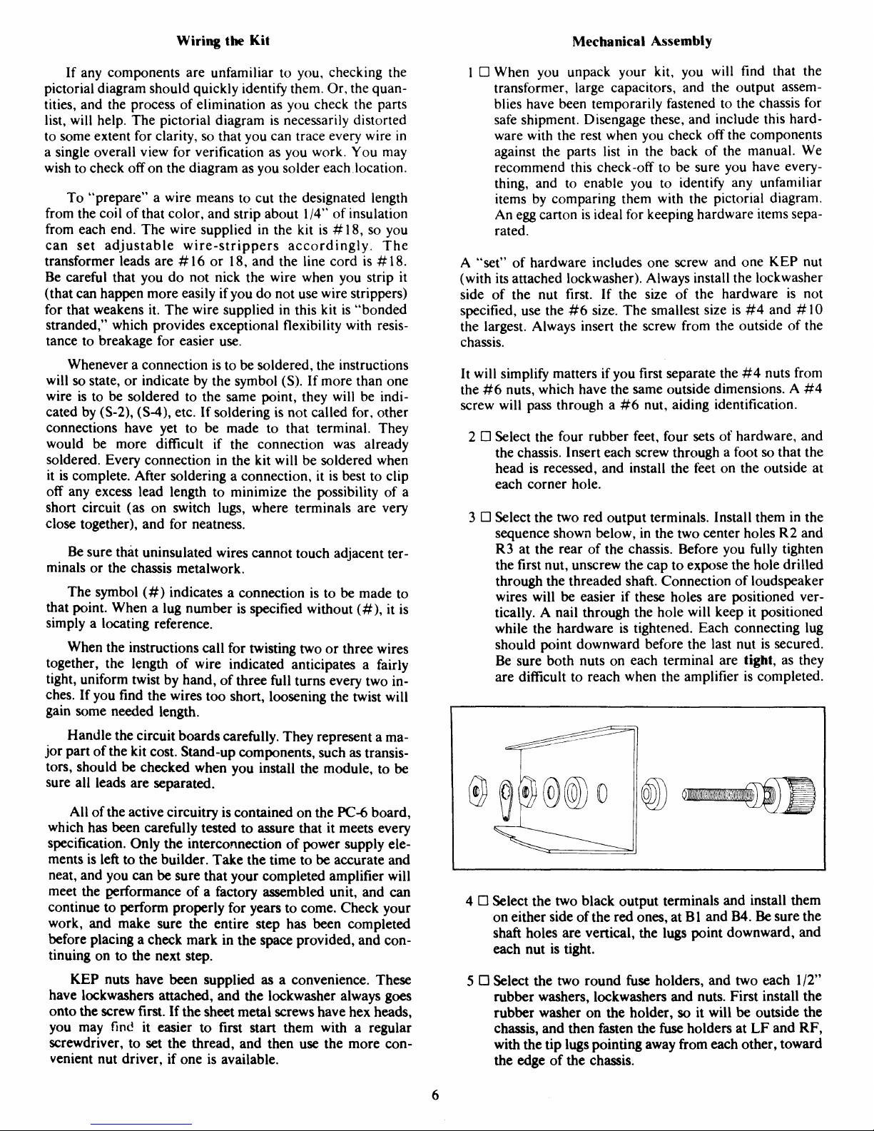
3 • Select the two red output terminals. Install them in the
sequence
shown below, in the two center
holes
R2 and
R3
at the rear of the chassis. Before you fully tighten
the first nut, unscrew the cap to
expose
the hole
drilled
through
the threaded shaft. Connection of loudspeaker
wires
will
be easier if
these
holes
are positioned ver-
tically. A nail
through the hole
will
keep it positioned
while the hardware is tightened.
Each
connecting lug
should
point downward before the last nut is secured.
Be
sure both nuts on each terminal are tight, as they
are difficult to reach when the amplifier is completed.
4 • Select the two black output terminals and install them
on
either side of
the
red
ones,
at Bl and B4. Be sure the
shaft
holes
are vertical, the lugs point downward, and
each nut is tight.
5 • Select the two
round
fuse
holders, and two each 1/2"
rubber
washers, lockwashers and nuts.
First
install the
rubber
washer on the holder, so it
will
be outside the
chassis, and then fasten the
fuse
holders at
LF
and
RF,
with the tip lugs
pointing
away
from
each other, toward
the
edge
of the chassis.
6
6 • Select the larger
round
input socket, its insulating disc,
the solder lug with lockwasher teeth, two #4 screws,
and
the two nylon nuts.
This
socket
will
be installed at
RS.
The inside of
the
chassis
at
RS
and
LS
has not been
painted,
so that a good ground connection can be
made. It may be necessary to clean this with a solvent,
or
with an eraser, before the
sockets
are installed. Place
the solder lug on the lower mounting screw inside the
chassis, followed by the insulating disc, then the socket.
Position
the lug toward the
edge
of the chassis. The
shorter
ground
lug on the socket should also be nearest
this right
edge.
Secure this socket with the nylon nuts.
7 • Select the other input socket and two
sets
of #4
hard-
ware. Install it at
LS
after cleaning the unpainted area,
with its short ground lug near the left
edge
of the
chassis.
8 • Select the four-lug rectifier block RB, the long #6
screw, and a nut. Install the rectifier in the center hole
near the rear of the chassis, with the plus (+) terminal
located over the tiny indexing hole at position four.
Correct
orientation of this rectifier is essential for
proper
wiring.
9 • Select the single
fuse
clip,
and one set of #4 hardware.
Install the clip in the right front
chassis
hole
FC,
closest
to the foot.
10 • Select the two
dual
fuse
clips and four
sets
of #4
hard-
ware. Install
these
in the pairs of
holes
FL
and FR on
either side of the center of the chassis.
11 • Select the two-lug terminal strip and one set of #4
hardware.
Install it in the front hole TS, next to the
single
fuse
clip.
Note the position of the mounting lug
(to the right) in the pictorial diagram.
NOTE:
Kits
provided
with
the
multiple
voltage
power
transformer
for
locations
outside
;K-
United
States
which
use a
line
(mains)
voltage
other
than
120
VAC,
are
also
supplied
with a five-lug
ter-
minal
strip
which
is
to be
installed
in
place
of
the
two-lug
strip,
using
an
additional
set
of
#4
hardware
near
the
dual
fuse
clip.
12 • Select the power switch. If
it
says
"Carting,"
position it
with
lug
#3 at the top. If
it
says
"Chicago,"
position the
small
protruding
plastic lug at the bottom. Snap it fully
into the front
chassis
hole PS
from
the outside.
A
soldering
iron
will
be used
regularly
for installing the wir-
ing.
Be sure you wipe its tip frequently with a damp cloth or
sponge, as a bright tip
will
make connections easier with
less
likelihood
of overheating components. If it is difficult to heat
a
connection in a couple of seconds, apply a small
amount of
fresh
solder to the tip so it can flow around the connection
and
provide good heat transfer.
Take
the time to observe the direction each wire
takes
from
its connecting lug, so that when you connect the first end, it
will
be pointing in the right direction.
This
makes the job
neater, and assures that each wire is long enough.
13 • Prepare a
6-1/2"
green wire. Connect one end to
dual
fuse
clip
FL
lug #
1.
Connect the other end to the other
dual
clip FR lug #1. (S).
14 • Prepare a
6-1/2"
white wire. Connect one end to FR
lug
#3. Connect the other end to
FL
lug #3. (S).
15 • Select the 2.2 ohm (red-red-gold) resistor. Cut each
lead
to 112" or
less.
Connect one end to the separate
solder lug installed under input socket RS. (S).
Con-
nect the other end to the short (ground) lug #2 of
socket RS.
16 • Prepare a 10" green wire and a 10" white wire. Twist
these
together uniformly (about three complete
twists
every two inches). Connect the green wire to the short
RS
lug #2. (S-2). Connect the white wire to RS lug
#
1.
(S). Place
these
wires out of
the
way, over the
edge
of
the chassis.
17 • Select one of the
.0047
mfd
film
capacitors. Cut each
lead
to 1/2", and connect one lead to
fuse
holder RF
lug # 1.
Connect the other lead to RF lug #2.
18 •
Prepare
two 8" white wires.
Start
with
one wire project-
ing
3/4" beyond the other, and
twist
them uniformly
together throughout their length. Connect the project-
ing
end to RF lug #1. (S-2). Connect the correspond-
ing
end of
the
other wire to
RF
lug #2. (S-2). Place this
pair
over the
edge
of the chassis.
19 •
Prepare
an 11" white wire
and a 9"
green wire. Starting
with the white wire 3/4" longer than the green wire,
twist
them together to within one inch of the other end
of
the green wire. At the beginning end, connect the
green wire to output terminal lug #B4. Connect the
white wire to lug #R3. (S). Place
these
wires off to the
right.
20 • Prepare a 6" green wire. Connect one end to lug #B4.
(S-2).
21 • Prepare a 10" white wire and a 10" green wire. Twist
them together, and connect the green wire to the short
LS
lug #1. (S). Connect the white wire to LS lug #2.
(S). Place
these
wires to the left, over the
edge
of the
chassis.
22 • Select the remaining
.0047
mfd
film
capacitor, and cut
each lead to 112". Connect one lead to
LF
lug #
1,
and
the other lead to
LF
lug #2.
23 • Prepare two
7-1/2"
white wires. Start with one wire
3/4" longer, and
twist
them together throughout their
length. Connect the longer end to LF lug #2. (S-2).
Connect
the other wire to
LF
lug # 1.
(S-2). Place
these
wires off to the left.
24 • Prepare a
9-1/2"
white wire and a 10" green wire.
Starting
with the white wire 3/4" longer than the green
wire,
twist
them together to
within
one inch of
the
other
end
of the white wire. At the beginning end, connect
the green wire to output
terminal
lug
#B1.
Connect
the
white wire to lug #R2. (S). Place
these
wires off to the
left.
25 • Prepare a 6" green wire. Connect one end to lug #B1.
(S-2).
7

26
• Prepare two 20" white wires, and
twist
them
together
throughout their length. Six inches in from one end of
the
pair,
cut one of the wires, and unwind it about
1-1'2"
in each direction from the cut. Strip 1 4" of
in-
sulation from each of
these
cut ends. Place the longer
portion
of the wire along the lower front
edge
of the
chassis, with the break at the single
fuse
clip. Connect
one cut end to
TS
lug #2. Connect the other cut end to
power switch lower lug #
1.
The unbroken w ire
of this
pair
may be placed under the power switch for neat-
ness,
and the free
ends
project from the front corners of
the chassis.
27 • Select
the power transformer, four
sets
of 1'2" long
#10 hardware, and the four flat washers. Position the
transformer
so that the red
leads
emerge near the
center of the chassis. The black and black/white
leads
(and all of the brown
leads
as well, if it is the multiple
voltage version) should project toward the power
switch. Be sure no wires are pinched in the installation.
Place the white twisted
pair
under the front
chassis
lip.
Install a flat washer on each screw through a
transformer
foot before the nut is secured.
The
transformer
leads
can be trimmed as desired for a
neat
job,
but be sure you do not cut any of
thern
too short (panic
ularly
if the multiple voltage version is used, and any change
in
the supply voltage is likely).
Cutting
the
leads
too short for
re-use may void the transformer warranty, if it is thought to
be defective. Alternate wiring diagrams tor the optional
multiple voltage version will be found
elsewhere
in this
manual.
If you have that transformer, consult them before
wiring
the transformer and power switch.
Be
sure all strands of each transformer lead are tinned and
soldered
together
before connection to a lug, so that there is
no
possibility of a stray strand touching anything but the in-
tended lug.
28
• Connect the black transformer lead to PC lug #2.
29
• Prepare a 2" green wire. Connect one end to FC lug
#2.
(S-2).
Connect the other end to
PS
top lug #3. (S).
30 • Connect the black/white transformer lead to TS lug
#2.
31 • Select
the yellow lamp assembly and the spring
steel
nut.
Trim
the lamp
leads
to 2", and install it from the
outside at
HT.
The center of the nut curves away from
the
chassis
when it is pressed over the lamp
case.
Be
sure it is pressed fully home, so the lamp is tight.
32 D Connect one lead
of
the lamp to
TS
lug #2.
(S-3).
Con-
nect
the other lamp lead to PS lower lug #1.
33 •
Select
the .005 mfd disc capacitor, and
trim
its
leads
to
1/2" or
less.
Connect one lead to PS lug #1.
(S-3).
Connect
the other lead to PS lug #2
34 •
Select
the AC line cord and the plastic strain relief.
Separate the two conductors for
2-1/2".
Cut
1-1/2"
off
of
one of the two leads, and strip 1/4" of insulation
from
each lead. Twist the strands tightly, and tin each
end.
Nine-and-a-half inches from the
longest
end,
make a sharp "V" in the cord by bending it back
sharply
on
itself.
Install the strain relief as shown, with
the small end of the strain relief nearest the stripped
end of the line
cord.
Crimp
the two halves of the strain
relief
around
the wire at the
"V"
with heavy pliers, to
partially
form it before insertion into the back panel.
Then
grip the larger diameter of the strain relief with
the tips of the pliers,
squeeze
it tightly, and insert the
end of the cord and the strain relief through the back
panel
hole
AC,
from the outside. Note that the hole has
a flat on one side, and the strain relief is installed ac-
cordingly.
It snaps into position when fully inserted.
Place the line cord under the other wires.
35 • Connect the longer end of the line cord to PS lug #2.
(S-2).
Connect the shorter lead to
FC
lug #1. (S).
36 •
Select
the two red transformer leads. Connect one lead
to RB lug #2. Connect the other lead to RB lug #3.
37 •
Select
the .01 mfd disc capacitor, and
trim
its
leads
to
3/4".
Strip
two 1/2"
pieces
of insulation from the white
wire,
and slide one piece over each of the disc capaci-
tor
leads. Connect one lead to RB lug #2.
(S-2).
Con-
nect
the other lead to RB lug #3.
(S-2).
38 • Prepare a 6" white wire. Connect one end to RB lug
#4. (S). Be sure this is the (+) terminal of the rectifier.
39 •
Select
one of the round capacitor brackets, two
sets
of
#6 hardware, one of the 3/4" #10
screws
and its nut,
two short #10
SEMS
screws
(with lockwasher at-
tached), two solder lugs, and one of the large capaci-
tors. Insert the short
screws
through the solder lugs,
and
install them loosely in the capacitor terminals. In-
stall the long screw in the bracket clamp, noting the
direction
of insertion in the pictorial diagram (to
pro-
vide
easy
future
access),
and tighten that nut about half
way. Place the assembly in position on the chassis, on
8

the right side, nearest the power switch. Install the two
sets
of hardware to secure the bracket to the chassis. If
the bracket
twists
as the
screws
are tightened, first in-
stall the capacitor, and clamp it.
Make
sure the capaci-
tor
is tight against the chassis, and that its positive ( + )
terminal
is toward the
right
side
of the
chassis
before
tightening the clamp. Position the lug on the ( + ) ter-
minal
(it will be painted red if it is not marked with a
+ ) so it points forward toward the power switch, and
tighten its screw. Point the
negative
terminal lug
toward
the rectifier block to the left, and tighten that
screw.
Make
sure no wires are trapped by the bracket.
40 •
Select
the remaining capacitor, its bracket, two
sets
of
hardware,
the long #10 hardware, the two short #10
screws, and the two solder lugs. Install this assembly as
in
the preceding
step,
but be sure the positive lug of the
capacitor is nearest the center, pointing toward the
other capacitor's
negative
lug. The
negative
lug of this
second capacitor points forward.
41 •
Select
the white wire from RB lug 4 (marked + ) and
connect it to CR lug #2.
42 • Prepare a
4-3/4"
white wire. Connect one end to FR
lug
#3.
(S-2).
Connect the other end to CR lug #2.
(S-2).
43 • Prepare a 6" green wire. Connect one end to RB lug
#1. (S). Connect the other end to
CL
lug #1.
44 • Prepare a
4-3/4"
green wire. Connect one end to FL
lug
#1.
(S-2).
Connect the other end to CL lug #1.
(S-2).
45 • Remove all of the insulation from a
2-3/4"
white wire.
Connect
one end to
CL
lug #2. (S). Connect the other
end to
CR
lug #1. (S).
46 • Connect the red/yellow transformer lead to the center
of
the bare wire
between
the capacitor lugs. (S).
47 • Connect the separate green wire from output terminal
Bl
to the center of the bare wire,
next
to the
transformer
lead. (S).
48 • Connect the separate green wire from B4 to the center
of
the bare wire also. (S).
49 •
Select
the output assembly modules (the two major
items
in the kit).
You
will
note
that the only difference,
which
identifies the
left
or the right module, is the posi-
tion of the thermal breaker, which is located
between
one
pair
of output transistors on the
heat
sink rib.
Before connecting wires to
these
modules it is
best
that
you
take the time to make absolutely certain that each
eyelet
is well soldered to the circuitry on the back (in-
side)
of the
board.
Add
a little solder if necessary, but it
is important that solder flow from the wire, across the
eyelet,
and onto the
circuitry.
Then
if
you
wish to clear
the center of the
eyelet
for easier insertion of the wire,
use a round wooden toothpick after heating each
eyelet.
Now position the right module (with the
breaker
at the front when the long row of
eyelets
is
next
to the
chassis)
with the circuit board up, against the
chassis.
Wires
will be connected from the top ot the
board,
and they
must be soldered to the underside.
Even
though the connect-
ing
wires will be rather long when the amplifier is completed,
they are just long enough to reach now, so working room is
limited.
It is
best
to
heat
the
eyelet
from below while the wire
is inserted from above.
That
requires
an
iron
with a small flat
chisel tip — and
some
care on your part. It is
easiest
to melt a
small
blob of solder on the tip, and position it under the
eyelet
so that the solder blob, more than the tip
itself,
is heat-
ing
the
eyelet.
If the
eyelet
is first filled with solder, and the
wire end pushed all the way through the heated
eyelet
first,
then withdrawn part way to
expose
a bit of the bare end
above the board before the solder cools, you should have a
firmly
soldered connection if it
cools
undisturbed.
Always
tin a wire that is to connect to an
eyelet.
After
solder-
ing,
go back and check by twisting each wire, to make sure
nothing
moves
on the other
side
of the
board.
Be careful, too,
that you don't loosen existing connections .to adjacent
eyelets.
For a bit better
access
to
these
connections, you may
wish to remove the three mounting
screws
to allow the circuit
board
to be moved, but don't forget the nylon washers under
the
board.
50 •
Select
one of the narrow numbered strips, and peel off
the backing.
This
identifies the
eyelet
numbers, and
should be placed along the bottom of the circuit
board,
with
eyelet
#14 nearest the power switch.
51 • Prepare a 6" white wire. Connect one end to
eyelet
#4
of
the circuit
board.
(S).
52 • Prepare a
5-112"
green wire. Connect one end to
eyelet
#13. (S).
Make
sure it cannot contact the transistor
mounting screw near the underside.
53 •
Select
the green and white twisted
pair
from
the output
terminals R3 and B4. Connect the shorter green wire to
eyelet
#6. (S).
54 •
Select
the
pair
of white wires from RF. Connect the
shorter wire to
eyelet
#8. (S). Connect the other wire
to
eyelet
#11. (S).
55 • Connect the remaining white wire from the green and
white
pair
from the output terminals to
eyelet
#12. (S).
56 • Connect the green wire from
eyelet
13 to FR lug #2.
(S).
57 • Connect the white wire from
eyelet
4 to
FR
lug
#4. (S).
58 •
Select
four of the long
sheet
metal screws.
Take
care to
see that no wires are pinched in the process, while you
tilt up and fasten the module to the end of the chassis.
59 •
Select
the green and white
pair
from input
socket
RS.
Connect
the white wire to the top rear
eyelet
# 1. (S).
Connect
the green wire to
eyelet
#2. (S).
This
pair
will
be specifically positioned later.
60 •
Select
the white
pair
at the front.
Tuck
the
excess
wire
into the corner of the chassis, and connect one lead to
each of the
lugs
on the thermal breaker. Solder each.
9

61 •
Select
the
left
output module, make sure all its
eyelets
are well soldered, and place it against the
left
side
of
the chassis, board up, breaker at the front.
62 •
Select
the
remaining
strip of
eyelet
numbers,
and
install
it with
eyelet
#3 at the front.
63 • Prepare a 6-1/2"
green wire. Connect one end to
eyelet
#13. (S). Be sure it cannot touch the transistor screw.
64 • Prepare a
5-1/2"
white wire. Connect one end to
eyelet
#4. (S).
65 •
Select
the green and white
pair
from output terminals
Bl
and R2. Connect the shorter white wire to
eyelet
#12. (S)
66 •
Select
the white
pair
from
LF.
Connect one wire to
eyelet
#11. (S). Connect the other wire to
eyelet
#8.
(S).
67 • Connect the remaining green wire from the output ter-
minal
pair
to
eyelet
#6. (S).
68 • Connect the white wire
from
eyelet
4 to
FL
lug #4. (S).
69 • Connect the green wire from
eyelet
13 to
FL
lug #2.
(S).
70 •
Select
four
sheet
metal
screws
and fasten the module to
the chassis, making sure no wires are pinched.
71 •
Select
the green and white
pair
from input
socket
LS.
Connect
the green wire to rear
eyelet
#2. (S). Connect
the white wire to
eyelet # 1.
(S).
72 •
Tuck
the
excess
of the remaining white
pair
of wires
into the
left
front corner
of
the chassis,
and
connect one
wire to each lug of the thermal breaker. Solder each.
73 •
Select
the 5 amp slo-blo
fuse
(a slo-blo
fuse
has distinc-
tive internal construction) and install it in the single
fuse
clip
FC.
74 •
Select
four 5 amp regular
fuses,
and install them in the
dual
fuse
clips
FL
and FR.
75 •
Select
the two 2
amp
fuses,
and install them in the
twist
type
fuse
holders on the back panel. These
fuses
will
provide
reasonable protection for most speakers. See
the
Operation
section of this manual for more detailed
information.
The remaining 5 amp
fuses
are alternates
for
the back panel holders for high power
test
pur-
poses.
76 • For
lowest
distortion performance, precise placement
of
some
wires is important. The wires from the output
terminals and the back panel
fuse
holders should be
kept against the chassis. They should be positioned
over to the input
socket,
and then straight forward to
the
board.
The input
socket
pairs
should be
close
to the
chassis, but above the other pairs, straight to the center
bottom of the circuit
board,
and then up the middle of
the board about 1/2" out, right in the plane defined by
the
edges
of
the
finned
heat
sinks.
The
wires to the dual
fuse
clips should be kept away from the board and
against the chassis, bringing the
excess
length forward
of
the
fuses.
The
leads
from the power supply capaci-
tors should be kept away from each
board.
The green
leads
from
the black output terminals to the power sup-
ply
should be brought
together
throughout most of
their length.
77 •
Check
all your soldered connections — especially
those
on the
fuse
clip lugs, which are
sometimes
difficult
to solder to.
Clip
off any
excess
bare wire
which
could short to adjacent
lugs
or the chassis. Pay
particular
attention to the stranded wires from the
transformer
and line
cord,
and check the power switch
connections. Now
turn
the amplifier upside down and
shake out any bits of wire or solder.
78 • Slide the cover in place, and install it with the
eight
sheet
metal screws.
79 • Remove the backing
from
the serial number label, and
apply
it to the bottom at the center rear.
CONGRATULATIONS!
YOU
HAVE COMPLETED ONE
OF
THE MOST
TECHNOLOGICALLY
ADVANCED
AND
SUPERB
SOUNDING
AMPLIFIERS EVER DESIGNED.
IF
PROBLEMS ARISE
A
great deal
of
care has
gone
into every
Hafler
amplifier,
whether kit or factory assembled, to be sure that it
meets
or
exceeds
all its specifications before it is shipped to you. Ev-
ery
assembled amplifier must
pass
a battery of performance
tests.
In the kit, each output module assembly was in-circuit
tested
to similar standards. Since
these
modules comprise all
of
the active amplifier
circuitry,
save
for the power supply, it
reduces the likelihood of an internal problem to near zero,
with careful assembly.
If you
are certain the problem
lies
in the power amplifier,
check first to see that the red pilot lamp is lighted. If it is on,
and
the yellow lamp is lighted, this indicates that the
thermal
safety
breaker on one channel has shut down the amplifier
because
of
excessive
temperature. In this
case,
the
heat
sink
will
be very hot to the touch.
After
a few minutes to cool, the
amplifier
will commence operation automatically. If it soon
shuts
down again,
and
the amplifier has sufficient ventilation,
the malfunction is either internal, or the result of an ex-
cessive
(and very likely inaudible) input signal.
If
neither lamp is lighted, the main
fuse
in the single
fuse
clip
on the
chassis
is probably open. If a replacement 5 am-
pere, Slo-Blo
fuse
also
blows, the amplifier
needs
service,
and
there is a power supply problem.
If a
problem
appears only in one channel
of
the amplifier,
it may be isolated from the rest of the amplifier by removing
the power supply
fuses
to that channel in the adjacent dual
fuse
clip. The other channel may then be operated
monophonicalfy. The
Hafler
company
does
not encourage
local
service of this amplifier. The one adjustment poten-
tiometer is sealed at the factory at the operating point for
lowest
distortion, and you should not readjust it. The ad-
10

vanced design of this circuit means that
some
components
will
not likely be available locally, and alternative replace-
ments
are not recommended at all.
We
recommend that a defective output module be sepa-
rated
from the amplifier, and returned for service at the fac-
tory.
This
reduces shipping
weight
and the likelihood of
damage, and
enables
you to operate the other half if you
wish. In this
case,
we
suggest
that the connecting wires be un-
soldered at the
eyelets;
that each wire be tagged with the
eyelet
number (visible inside the
board,
along the
edge
— or
see the board diagram in this manual); that the bare wire
ends
all be insulated; the dual power supply
fuses
for that
channel be removed; and the wires to that thermal breaker
on
the
heat
sink fin be disconnected and temporarily
soldered
together,
and insulated.
SERVICE
POLICY
AND
LIMITED
WARRANTY
The
DH-200 Power
Amplifier
has been carefully
engineered to provide many years of use without requiring
any maintenance or servicing.
Factory
assembled units are subjected to several physical
and
electrical
tests
before shipment.
The
output
circuit
board
assemblies
of kit units are similarly
tested
prior
to shipment.
In
spite
of all this testing, shipping damage
does
occur, kits
are not assembled properly or
someone
"goofs"
and service
and/or
maintenance will be required. The
David
Hafler
Co.
provides complete service facilities at the factory to make
any necessary repairs.
It is the owner's responsibility to
return
or
ship
the
unit
freight
prepaid
to
the
factory
service
department.
Units
ship-
ped
freight
collect will
not be
accepted.
For
units
to be
repaired
under
warranty a copy
of
the
dated
bill
of
sale
must
accompany
the
unit.
Shipment should be made via
UNITED
PARCEL
SER-
VICE.
Parcel Post is not a
safe
way to ship electronic equip-
ment. The factory will not be responsible for damage caused
by
parcel
post
shipment and repairs will be made at the
owner's
expense.
When shipping your DH-200 be sure to in-
sure it for the
full
value of an assembled amplifier.
Use the original carton and packing material to ship your
amplifier.
Enclose with the unit the following information:
1. Complete shipping address
(Post
Office Box numbers
are often not acceptable).
2. The serial number.
3.
Copy
of dated
bill
of
sale
if
repairs
are to be made under
warranty.
4. Description of the malfunction. If intermittent,
please
note.
5. We
also
suggest
further identifying the unit as yours by
putting a label on the bottom or tieing a label with your
name and address on the line
cord.
All
service work is guaranteed for 90 days.
Warranties
apply to the original purchaser only.
Warran-
ties
are void if:
1. The amplifier has been either physically or electrically
abused or used for
some
purpose for which it was not
designed.
2. The amplifier has been modified without factory
authorization.
The
transformer warranty is void if the
leads
have been
cut too short for reuse.
If you
think a transformer is defective
the
leads
must be unsoldered, not cut, for its return.
Technical
assistance
to help you locate the source of a
problem
may be obtained by writing the Technical Services
Department. It is helpful to know the serial number of the
unit
and the results of any
tests
you have performed.
SERVICING
AN
AMPLIFIER MODULE
If
you are certain that the problem is confined to one of
the amplifier modules (comprising the circuit
board,
heat
sink,
and output transistors), you may remove and return
only the module for service. Be sure that the components on
the circuit board are well protected — as by a surrounding
sleeve
of corrugated cardboard which
rests
against the
heat
sink,
and projects beyond the components. Properly packed
and
insured for $150, this assembly can be
sent
by parcel
post, as well as
UPS,
if necessary. A service fee of $20 must
be
sent
with
every
module, since the fault may have been
caused by a wiring
error
elsewhere.
For
this reason, too, and
because
we have no control over its
proper
reinstallation, the
service
warranty
on a separate module is limited to assurance
of
its proper functioning when it
leaves
the service facility.
All
modules are
tested
before return to you. If you believe
the fault is the factory's warranty responsibility, include the
serial
number and the
bill
of
sale.
If in our judgement the
fault is entirely a manufacturing
defect,
a portion of the ser-
vice fee will be refunded.
Only
a complete amplifier can be
completely checked and given a service warranty.
WARRANTY FOR KIT-BUILT
UNITS
The
parts in a DH-200 kit are warranted for a
full
year
from the purchase date. If a defective component is found on
a
circuit
board
or in a kit, simply
return
the
individual
part
to
the factory prepaid
together
with the serial number and the
date of purchase, and it will be replaced at no charge.
If
you cannot locate what is wrong with your DH-200,
return
it to the factory with a copy of the dated
bill
of
sale,
and
a check for $40. If the
sole
cause
of the
problem
is a de-
fective part, the unit will be repaired and returned to you
transportation
prepaid, and your $40
less a charge
for re-
packaging
and
shipping
will be
returned
to
you.
If the
prob-
lem is found to be an
error
in your assembly of the
ampli-
fier,
the amplifier will be put in proper working
order,
test-
ed to be sure it is meeting specifications, and returned to
you
(freight prepaid within the continental U.S.). Excess
shipping
charges for expedited service, or
overseas
delivery
are your responsibility. At the
sole
discretion of the factory
service department, if the time required for diagnosis,
repair
and testing, and the nature of the malfunction war-
rants it, a portion of the submitted repair fee may be
rebated.
This
warranty is void if the kit has not been completely
assembled or if other than rosin core solder has been used.
Units
assembled with acid core solder or
paste
flux will be
returned
unserviced.
WARRANTY FOR FACTORY ASSEMBLED
UNITS
The
DH-200 is warranted for a
full
year from the
purchase date including parts and labor and
normal
shipping
costs
from the factory to the owner within the continental
U.S.
The owner is responsible for returning the unit to the
factory and must submit a copy of the dated
bill
of
sale.
This
warranty
gives
you specific legal rights. You may
also
have other rights which vary from
state
to
state.

AC
LINE
CONNECTIONS
FOR
OVERSEAS
USE
The
power transformer supplied in DH-200 amplifiers
sold in the USA is intended for 120 volt, 60 Hz operation
only. For use in other countries, a multi-voltage transformer
is available at higher
cost.
It has dual tapped
primary
wind-
ings
which can be arranged in various series-parallel com-
binations for 100, 110, 120, 200, 220 and 240 volt 50 or 60
cycle lines. The schematic diagram
details
the wiring com-
binations which are represented pictorially here.
Note that a 5-lug terminal strip is required when the
multi-voltage transformer is used.
This,
and the
100,000
ohm
resistor which is
sometimes
needed to illuminate the
pilot lamp, is supplied in kits which include the special
transformer.
If the amplifier is operated with 200 to 240 volt
lines, the 5 amp line
fuse
which is supplied should be
replaced with a 2-1/2 amp Slo-Blo type
fuse.
12

KIT
PARTS
LIST
Minor
variations
may sometimes
be
encountered
in
value
or
appearance. These will
not
affect
performance.
13
Fuse
Envelope
Part
No.
6
Fuse, 5 ampere
341050
1
Fuse, 5 ampere, Slo-Blo
342050
2 Fuse, 2 ampere
341020
Hardware
Envelope
Part
No.
1
Lug,
solder type, internal tooth,
#6
619308
4
Lug,
solder type,
#10
629508
8
Nut,
#4-40
KEP
614245
9
Nut,
#6-32
KEP
614345
4
Nut,
#10-32
KEP
614565
2 Nut,
#10-32
KEP,
for
clamp
614569
1
Nut, spring
steel,
Tinnerman
type
610041
2 Nut,
#4-40
nylon
694241
2
Nut, 1/2", for fuse
holder
615074
10
Screw, machine,
#4 x
5/16" 611255
8
Screw, machine,
#6 x 1/2"
611385
4
Screw, machine,
#10 x 1/2"
611585
2 Screw, machine,
#10 x 3/4"
for
clamp
611579
4
Screw,
#10 x 1/4",
SEMS
611545
16
Screw,
sheet
metal,
#6 x 1/2"
612387
1
Screw, machine,
#6 x
3/4" 611375
4
Washer, flat
7/8" 616575
2 Washer, locking, internal tooth,
1
/2"
for fuse
holder
617085
2 Washer, rubber,
1/2" for
fuse
holder
696081
1
Chassis
711007
1
Cover
711008
2 Capacitor,
10,000
mfd,
75V 294103
2 Bracket, round,
for
capacitor
717058
1
Diode rectifier block
544252
4
Feet, rubber
899757
2 Fuse holder, round
351003
1
Fuse clip,
single
351002
2 Fuse clip, dual
352001
1
Indicator light assembly
526001
1
Input
socket,
round
351318
1
Input
socket,
narrow
351326
1
Insulator disk, round,
for
socket
815318
1
Label,
serial number
808005
1
Line
cord,
with plug
322001
2 Output module assembly
(1
each,
left
and right)
994001
2 Output terminal, black, with hardware
351005
2 Output terminal, red, with hardware
351006
1
Power switch
332001
1
Strain relief, plastic
895001
1
Terminal
strip, 2 lug 373181
alternate 5 lug
for
international
use
377181
1
Transformer, power
464002
alternate
for
international
use 464003
1
Wire,
white,
#18
1
Wire,
green,
#18
1
Registration card
Small
Parts
Envelope
part
No.
1
Capacitor,
.01
mfd, disc
238103
1
Capacitor,
.005
mfd (5000M), disc
238502
2 Capacitor,
0047
mfd film
264472
1
Resistor,
2.2
ohms
133022
2 Numbered strip,
for eyelets 808101

SCHEMATIC
DIAGRAM
©
Copyright 1980.
All
rights reserved.

COMPONENT
VALUES
Part
No.
Rl
470,000
ohms
139474
R2
2,200
ohms
139222
R3
22,000
ohms
139223
R4
100
ohms
139101
R5
100
ohms
139101
R6
2,200
ohms
139222
R7
2,200
ohms
139222
R8
330
ohms
139331
R9
22
ohms
139220
RIO
22
ohms
139220
Rll
39,000
ohms
139393
R12
560
ohms
139561
R13
39,000
ohms
139393
R14
560
ohms
139561
R15
22
ohms
139220
R16
22
ohms
139220
R17
2,200
ohms
139222
R18
330
ohms
139331
R19
2,200
ohms
139222
R20
100
ohms
139101
R21
100
ohms
139101
R22
22,000
ohms
139223
R23
2,200
ohms, 1 watt
136222
R24
560
ohms
139561
R25
100
ohms
139101
R26
1,800
ohms
139182
•R27
100
ohms
139101
R28
47
ohms,
carbon
comp.
119470
R29
1,000
ohms
139102
R30
470
ohms
139471
R31
220
ohms,
112 watt
133221
R32
1,800
ohms
139182
R33
100
ohms
139101
R34
47
ohms,
carbon
comp.
119470
R35
2,200
ohms, 1 watt
136222
R36
1
ohm,
5 watt, 10% w.w.
120010
R37
10
ohms
139100
R38
10
ohms,
2 watt
190100
R39
0.5
ohms,
1/2 watt
133509
R40
220
ohms,
1/2 watt
133221
R41
220
ohms,
1/2 watt
133221
R42
220
ohms,
1/2 watt
133221
R43
220
ohms,
112 watt
133221
R44
100,000
ohms,
1/2 watt
133104
R45
2.2
ohms,
112 watt
133022
PI
1,000
ohms
trimpot
100102
Fl
Fuse
5A
Slo-Blo
3AG
342050
F2
Fuse
5A, 3AG
341050
F3
Fuse
5A, 3AG
341050
F4
Fuse
2A, 3AG
341020
Tl
Power
Transformer
464002
T2
Power
Transformer,
International
464003
CI
10
mfd,
16 V,
non-polarized
electrolytic
203106
C2
390
pF,
500V,
Mica
257391
C3
0.001 mfd,
100V, Film
264102
C4
0.001 mfd,
100V, Film
264102
C5
470
mfd, 6.3V,
non-polarized
electrolytic
202477
C6
270
pF,
500V,
Mica
257271
C7
100
mfd,
80V,
Electrolytic
294107
C8
0.1 mfd,
100V, Film
264104
C9
680
pF,
500V,
Mica
257681
C10
100
mfd,
80V,
Electrolytic
294107
Cll
0.01 mfd,
100V, Film
264103
C12
0.1 mfd,
100V, Film
264104
C13
390
pF,
500V,
Mica
257391
C14
0.005
mfd,
1000V,
Disc
238502
C15
0.01 mfd,
1000V,
Disc
238103
C16
10,000
mfd, 75V,
Electrolytic
294103
C17
10.000
mfd. 75V.
Electrolytic
294103
C18
680
pF,
500V,
Mica
257680
C19
0.0047
mfd, 100V, Film
264472
C20
0.01 mfd,
100V, Film
264103
C21
0.01 mfd,
100V, Film
264103
Dl
1N4148
544148
D2
1N4148
544148
D3
1N4148
544148
D4
1N4148
544148
D5
1N4148
544148
D6
1N4148
544148
D7
1N4148
544148
D8
1N5240B
540510
D9
1N5240B
540510
D10
1N4148
544148
Dll
1N4003
544102
D12
1N4003
544102
D13
1N4003
544102
D14
1N4003
544102
DB1
Diode bridge
544252
Ql
2N5550
572550
Q2
2N5550
572550
Q3
2N5550
572550
Q4
2N5401
562401
Q5
2N5401
562401
Q6
2N5401
562401
Q7
2N5401
562401
Q8
2N5415
562415
09
NP2222
572222
Q10
2N5550
572550
Qll
2N3440
572440
Q12
2N3440
572440
Q13
2N5415
562415
Q14
2SK134
571134
Q15
2SK134
571134
Q16
2SJ49
561049
Q17
2SJ49
561049
15
All
resistors
are
1/4
watt
5% carbon
film
unless
otherwise
noted.

SPECIFICATIONS
Power
Rating: Less than 0.02% total harmonic distortion
at any power
level
up to 100
watts
continuous average
power per channel into 8 ohms at any frequency
bet-
ween 20 Hz and 20 kHz
with
both channels driven.
IM
Distortion
(SMPTE): Less than 0.005"* from 1 watt
to 100
watts
into 8 ohms.
Typical THD at 100
watts
into 8 ohms:
1 kHz — 0.0015%
10 kHz — 0.005^
20 kHz — 0.012^
Frequency
Response
into 8 ohms:
-
3 dB, 1 Hz to 100 kHz at 1 watt
±0.5dB,
10 Hz to 40 kHz at 100
watts
Typical Channel
Separation:
20 Hz: 66 dB
1 kHz: 66 dB
20
kHz:
60 dB
Signal
to
Noise
Ratio,
unweighted:
Better than 100 dB
at 100
watts
into 8 ohms.
Input
Impedance:
22,000 ohms.
Input
Sensitivity:
1.5 volts rms for 100
watts
into 8 ohms.
Damping Factor: 150 to 1 kHz into 8 ohms
50 to 10 kHz into 8 ohms
Rise
Time: 10 kHz, 60 volts peak to peak
square
wave,
\09< to
907c
: 2.5/is.
Slew
Rate:
10
kHz,
60 volts peak to peak
square
wave: 30
V/M s.
Semiconductor
Complement:
26 transistors, 8 power
Mosfets,
24 diodes, 4 zener diodes, 1 diode bridge.
Power
Consumption:
Quiescent: 101)
VA;
100
watts
into
8 ohms: 370
VA.
Size:
5-1/8" high, 16" wide, 10-1/2" deep.
Net
Weight
26 lbs.
Shipping
Weight:
30 lbs.
16
All
Specifications are subject to change without notice.

HAFLER
DH-200
STEREO POWER
AMPLIFIER
PICTORIAL
DIAGRAM
POWER TRANSFORMER
120
Volt
AC Line
Connections shown
OUTPUT MODULE ASSEMBLY
©COPYRIGHT
1980.
ALL
RIGHTS
RESERVED


 Loading...