

Page 1

Page 2
LIMIT
MODE2MODE1 BRIDGESTEREO
ACTIVE
SIG
STEREO
POWER
0
-
∞
CH 1
PROFES SIONA L POWER A MPLIF IER
0
-
∞
CH 2
PROTECT/CL IP
BRIDGE
DH Series professional
power amplifier
DH500
DH700
DH900
DH1200
DH1400
DH1800
Page 3
LIMIT
MODE2MODE1 BRIDGESTEREO
ACTIVE
SIG
STEREO
POWER
0
-
∞
CH 1
PROFES SIONA L POWER A MPLIF IER
0
-
∞
CH 2
PROTECT/CL IP
BRIDGE
1
1
58 9
6
2
3
4
7
6
1
2
3
4
5
6
7
8
9
Ple ase rea d th e basic p ro tecti ve m ea sure as b elow be fore us in g
1.P lease r ead all t he safe ty i ns truct ion bef ore usi ng the pr oduct .
2.T his pro duct mu st be ear thed. If it sho uld be ma lf un ction o r bresk
dow n,gro undin g provi des a pat h of leas t resis tance f or elec tr ic c urren t
to re duce ri sk of ele ctric s ho ck .
Thi s produ ct is equ ipped w ith a cor d havin g an e qu ipmen t-gro uding
con ducto r and a gro undin g plug. The plu g must be p lu gg ed in to an
app ropri ate out let tha t is p ro perly i nstal led and e ar th ed in acc ordan ce
wit h all loc al code s an d or dinan ce.
- .
.
- ,
.
3.To r ed uce the r is k of i njury, cl ose sup er vi sion is n ec es sary wh en
the p roduc t is used n ear chi ldren
DANGER Imp roper c on necti on o f th e equip me nt gr oun ding
con ducto r can res ul t in a risk o f el ec tric sh oc k Che ck with a
qua lifie d elect ricia n or s er vi cem an if you a re in dou bt a s to
whe ther th e produ ct i s pro pe rl y gro un ded D o not mod ify the p lug
pro vi ded wit h th e produ ct if i t wi ll n ot fi t the out let h ave a
pro pe r outle t in st alled b y a qu al ified e le ct ricia n
.
4.D o not use t his pro duct ne ar wate r-for e xa mple, ne ar a b athtu b,
was hbowl ,kitc hen sin k,in we t basem ent or me ar a s wi mming p ool
or th e lake.
5.T his pro duct ma y be capa ble of pr od uc ing sou nd leve ls that c loud
cau se perm anent h earin g lo ss .Do not o perat e for a lon g perio d of
tim e at high v olume l ev el o r at a leve l th at i s uncom forta ble.I f yo u
exp erien ce any he aring l os s or r ingin g in the ea rs,yo u shoul d consu lt
an au diolo gist.
6.T his pro duct sh ould be l ocate d so that i ts l oc ation o r posit ion doe s
not i nterf ere wit h its pro per ven ti la tion.
7.T his pro duct sh ould be l ocate d away fr om heat s ou rc es such a s
rad iator s,hea t regis ters or o ther pr od uc ts that p roduc e heat.
8.T he prod uct sho uld be co nnect ed to a pow er s up ply onl y of the ty pe
des cribe d on the op erati on inst ru ct ions or s a marke d on the pr oduct .
9.T his pro duct ma y be equi pped wi th a pola ri ze d line pl ug (o n blade
wid er than t he othe r).Th is is a saf ety fea tu re .If you a re unab le to
ins ert the p lug int o the out le t, conta ct an ele ct ri cian to r ep la ce your
obs olete o utlet .Do not d efeat t he s af ety pur pose of t he plug .
10. The pow er-su pp ly cord o f th e pr oduct s ho ul d be unpl ug ge d from
the o utlet w hen lef t unuse d for a lon g pe ri od of tim e.
Whe n unplu gging t he powe r-sup pl y cord, do n ot p ull on th e co rd ,
but g rasp it b y the plu g.
11.Car e shoul d be take n so that o biect d o not fal l an d li quid ar e not
spi lled in to the en closu re thro gh o pe ning.
12. The pro duct sh ould be s ervic ed by ser vice pe rsonn el when :
A.T he powe r-sup pl y cord or t he p lu g has bee n da ma ged;o r
B.O bject s have be en fall en,or l iq ui d has bee n spill ed into t he
pro duct; or
qua lifie d
IMPORTANT SAFETY INSTRUCTION
C.T he prod uct has b een exp osed to r ain;o r
D.T he prod uct doe s not app ear to op erate n or ma lly or ex hibit s a
mar ked cha nge in pe rform an ce ;or
E.T he prod uct has b een dro pped or t he encl os ur e damag ed.
13
. - .
.
. - '
,
.
.
/
.
. -
.
.Do n ot atte mpt to se rvice t he p ro duct be yond th at desc ribed i n
the U se r ma in te nance i ns tr uctio ns
All o ther se rvici ng shou ld be ref erred t o qu al ified s ervic e perso nnel
15 Th e po wer su pp ly cord s ho ul d be unpl ug ge d from th e ou tl et
whe n the pro ducts i s compl etely p ow er o ff fr om t he e lectr ic p ow er
sou rces an d elect ric net wo rk s
14 Do no t place o bject s on the pr od uct s po we r
cor d or plac e it in a pos ition w here an yo ne coul d tr ip o ver w al k
on or r ol l anyti ng o ve r it Do n ot a ll ow th e produ ct t o res t on o r
to be i nstal led ove r power c ords of a ny type I mp rop er
ins talla tions o f this ty pe cres ts t he poss ib il ity of fi re h azard a nd
or pe rsona l injur y
WARNING
≤2000m
CA UTI ON
RISK OF ELECTRIC SHOCK
DO NOT OP EN
CAUTION :
( )
-
TO RE DUCE TH E RIS K OF EL EC TR IC
SHO CK DO NOT R EMOVE C OV ER OR BA CK NO
USE R SE RVIC EA BLE PARTS IN SIDE RE FE R SERVICI NG
TO QU ALIFI ED P ERSON NE L
The lightning flash with arr ow he ad s yn bo l wi th in
an equilateral triangle is i nt en de d to a le rt t he u se r
to the presence of uninsulat ed d an ge ro us v ol ta ge
within the product's enclo su re ,t ha t ma y be o f
suffi ci en tm agnitude to constitute a risk of electric
shock to persons
The exclamation point with in a n eq ui la te ra l tr ia ng le
is intended to alert the user to t he p re se nc e of
important operation and ma in te na ce (s er vi ci ng )
instruction in the literat ur e ac co mp an yi ng t he
appliance.
Only use it below the attiude of 2 00 0m s fo r sa ft y
application.
Only use it in nontropical cli ma te c on di ti on f or
safty application
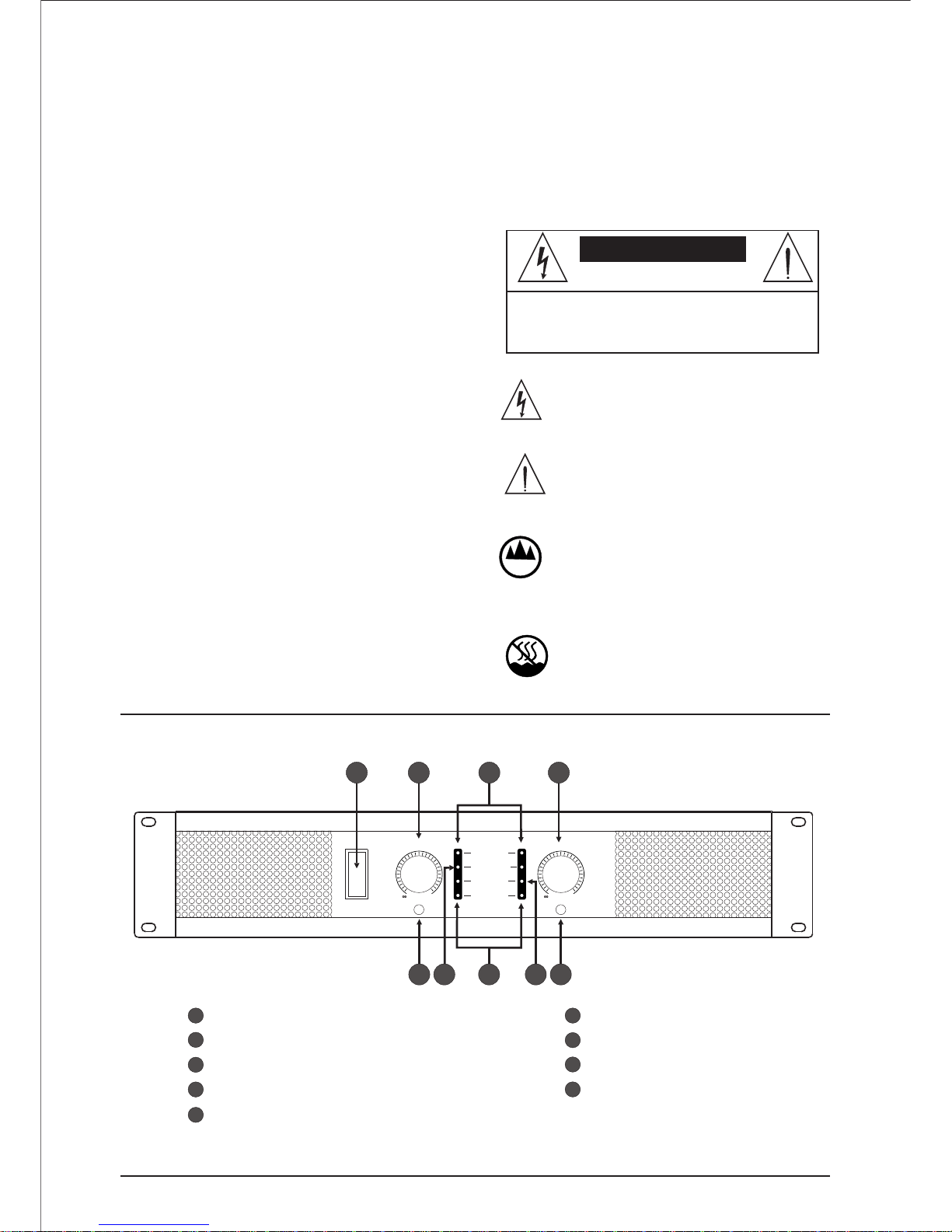
Front Panel
CH 1 volume knob
SIGNAL
CH 2 volume knob
POWER
PROTECT/CLIP in di ca to r
ACTIVE indicator
STEREO/BRIDGE indica to r
LIMITER MODE1/MODE2 sw it ch
STEREO/BRIDGE switch
V1.0
Page 4

2
2 179 5
36
48
10
1
!"#$
%&
1 2
'()*
-./$
01+/$
3
4
23
/$
+,/$+,)*
+, /45(67)
-.
2 3
Speaker
1
2
3
4
5
6
6
7
8
9
10
Introduction to rear panel controls
fuse
CH 1 line input XLR interface
CH 1 line output XLR interface
CH 2 line input XLR interface
CH 2 line output XLR interface
CH 1 speaker SPEKON output i nt er fa ce
CH 1 speaker Bindding Post o ut pu t in te rf ac e
CH 2 speaker SPEKON output i nt er fa ce
CH 2 speaker Binding Post ou tp ut i nt er fa ce
AC Cord
System connection diagram
Speaker
Speaker
Speaker
(or other audio input device s)
KARAOKE eff ector
line input 1
line input 1
line input 2
line input 2
Output 1
Output 1
Output 2
Output 2
can be used for Hand by Hand set ti ng s
Or connecting other audio eq ui pm en t
FUSE: T15AL /250V
POWER RATI NG 220Va c/50H z 2A:
FUSE: T15AL /250V
POWER RATI NG 220Va c/50H z 2A:
Page 5

Balance
1
2
3
+
-
2
1
+
3
3
1
!"#$
%&
1 2
89:;
'()*
-./$
01+/$
3
4
23
'(/$
+,/$
+,)*
+,+</45(67)
-.+<
'(+<
'(
2 3
1+
2+
2-
1-
+
-
Function feature
2 output modes: Stereo & Bridg in g
Complete protection circ ui t: o ve rh ea t, o ve rl oa d, s ho rt c ir cu it
protection
High effi ci ency cooling: variable speed fan + high efficiency
radiator
2U size, easy to install
Limit function
Low distortion
Balanced XLR input
Eff ic ie nt h ea t radiator, the built-in for ce d ai r co ol in g sy st em ,
faster and more uniform sp re ad h ea t, P ro vi de a dd it io na l
protection to power amplif ie r, in cr ea se p ow er o utput
Open the package
Please open the package and ca re fu ll y ch ec k for any damage
during shipping. If disc ov er d am ag e, p le as e no ti fy s hi pp in g
company immediately. The c on si gn ee h as t he right to claim for
damage to the carrier.Please save all t he p ac ka gi ng m at er ia ls f or
the service of the factory, which rarely happens.
1
.Installation
Note: when connected with th e po we r am pl if ie r, al ways rotate the
volume counter anticlock wi se t o co nt ro l to m in im um . This w il l
reduce the howling, preven t da ma ge t o th e sp ea ke r.
Important: the following g ui da nc e ca n he lp y ou q ui ck ly a nd
easily install the power amp li fi er, r ea dy t o ru n.
Select the operation of the mo de a cc or di ng t o 2. 2, S ec ti on 2 .1
description.
Input sensitivity, load protection, AC power requirement s in
Section 2.3.
Operation of mode selectio n ac co rd in g to t he 2 .1 ,2 .2
specification.
The input sensitivity, protection, AC power load requireme nt s
in section 2.3.
1.1 install the amplifier in t he s ta nd ar d 19 i nc h (4 8. 3 cm ) br ac ke t
or placed on the stable flat.
The installation size is lon gt h1 9 in ch es ( 48 .3 cm ), h ig h 3. 5 in ch es
(8.9 cm). depth 16.6 inches( 42 .3 cm )
In front of the power amplifier
Don't block air flow
Air flow
43.5cm
42.3cm
Power amplifier
(top view)
Impo rtant: ens ure that the b ack of the power
Air flow
ampl ifier is sup ported
Air flow Air flow
1.2 use high quality speak er c on ne ct io n ca bl e to c on ne ct t he s pe ak er.
1.3 use the shielded wire conn ec ti on s ou rc e. S uc h as t he b al an ce
of the following figure, the n on - b al an ce d li ne a ls o ca n be u se d.
(optional barrier type inp ut i nt er fa ce w it h PM -B B ac ce ss or ie s)
Ground
Input
From the power
amplifier out
Non Balance
From the power
amplifier out
Shield
Input
2.1 stereo
1 reduce the level of control (c ou nt er cl oc kw is e ro ta ti on i n th e
end), off t he p ower amplifier.
2 front panel switch is set to S TE RE O.
3 connect input and output cab le .
4 open the amplifier, a dj us t th e le ve l of e ac h ch an ne l by u sing the
level of the front panel.
2 Introduce.
KAR AOKE ef fecto r
(or o ther au dio inp ut devi ces)
Spe aker
Spe aker
lin e input 2
lin e input 1
Out put 1
Out put 2
Fro nt pane l:
Cho ose STE REO
Set s tereo
Stereo connection
2.2 bridg e Mono
1. reduce level control (clo ck wi se ), c lo se t he p ow er a mp li fi er.
2 .front panel switch, set to BR ID GE .
3. connect input and output ca bl e. O nl y th e in pu t ch an ne ls C H 1
are available.
4 make sure that the load is balan ce d (a ny o ne s id e is n ot
grounded), and can not be us ed b la ck c ol or ( -) - w ir e co lu mn .
5 open amplifier, a dj us t le ve l co nt ro l. O nl y th e in pu t channels
CH 1 are available.
Front panel:
Select BRIDGE, set to brid ge
Warning:
Bridge-Mono mode
must be used for
impedance 8Ώ.
The sp eaker X LR (SPE AKON) c onnec t
Brid ge conn ectio n mode
Spe aker Spe aker
The brid ge connec ts t he conjun ction of way
Page 6

(220V/50Hz)
10A: D H 500 /D H 700 /D H 900 A A A
15A: D H 1200/D H 1400 /D H 1800 A A A
TPC
Automatic
c
c
c
0
20
10
c
c
c
c
40
30
60
50
At 75 C°
60
c
c
c
80
70
90
C
80
C
90
Out put the signal
C
4
2.3 AC po wer requi re men ts
This series of power ampli fi er i s eq ui pp ed w it h su it ab le p ow er
cable and plug.If possib le , us e th e sp ec ia l wi re p ow er o ut le t. M ak e
sure that the correct voltag e an d cu rr en t ar e av ai la bl e. D on 't b e in
use the power amplifier belo w 10 % of t he r at ed v ol ta ge .
connect the machine to the cor re ct p ow er s up pl y. Use of the
three core power supply co rd w e pr ov id e.
Note:
3 operation
Although the power amplifi er i s pr ot ec te d ag ai ns t ex te rn al e rr ors,
the following preventive m ea su re s ar e re co mm en de d:
1 stereo, bridge - Mono oper at io n mo de h as i mp or ta nt d iffe re nc es .
Please refer to section 2.
2 only in the case of the shutdown , th e ST ER EO /
BRIDGE switch can be adjus te d
determine the correct sett in g fo r th e ST ER EO /B RI DG E
switch. Reference 2.1, 2 .2 s ec ti on .
3 cable, select the signal sou rc e, a dj us t th e ou tp ut o f th e el ec tr ic
usually careful operatio n.
4 the cable output cable can not c on ne ct t o th e si gn al i np ut g ro un d.
Otherwise cause earth loop , as w el l as O sc il la ti ng .
5 supply power supply volt ag e of t he p ow er a mp li fi er c an n ot
exceed 10% of the upper and lowe r li mi ts , an d ca n on ly w or k at
rated frequency.
6 don't connect the output to th e po we r ou tp ut , ba tt er y an d po we r
source. Otherwise caus e el ec tr ic s ho ck s.
7 the unauthorized modific at io n of t he c ir cu it o r th e un au th or iz ed
modification of the circui t ma y ca us e da ng er, an d ma ke the
warranty liability inval id . The company will not respo ns ib le f or
the damaged caus e excessive driver for other systems
3.1 prevent ion
warning:
Note:
3.2 power ind icator
3.3 signa l protection circuit
When the green power indicat or i s on , it i nd ic at es t ha t th e po we r
amplifier is open, and the low v ol ta ge s up pl y ca n ma ke s ho wi ng
light.
When the input and output sign al f lo w de vi at e gr ea tl y, th e
internal signal pressure l im it p ro te ct io n ci rc ui t au to ma ti ca lly
reduce gain, to prevent the in te rn al
nonlinearity of the amplif ie r du e to o ve r ex ci ta ti on , ov er lo ad , or
error. and to keep the signal waveform is n ot c ha ng ed u nd er a ny
conditions. The circuit keeps the distortion of the sign al c ur re nt
below 0.5%, thus ensurin g a cl ea r so un d an d effective spea ke r
protection.
4 technical specifications
Without spe ci al p ro vi si on s, a ll t he p ow er a mp li fier specifications
are in the following setting s: s te re o mo de t yp e, 8 ,38.5db input
sensitivity.Power specifications
Output power: the follow in g sp ec if ic at io ns c an b e gu ar an te ed a t
least the power of the standar d 1k Hz .
Channel 1
Ω
Level control
Level control
Channel 2
Front panel level control
The follo wing diagram sh ows the action of t he
heat mana gement system :
Rad iator t emper ature
The rmal pr otect ion cir cuit (T PC)
Mut e
Act ivate T PC
lim its
Fan s peed
Min imum fa n speed ,
TPC n ormal
Fan s peed
Load impe dance: all k in ds o f lo ad c an b e us ed .
Stereo mode 4 8 ;
Bridge M on o: 8 .
: -
-
Ω
Ω
AC power su pp ly: the back plate of each machine provides
current, frequency and vol ta ge r eq ui re me nt s
Idle power co nsumption: ≥90W.
The maximum current
Control
Power:
Level:
Stere o / mo no :
Input interface:
Input impedance:
Output:
Output impedance:
DC output offset:
front panel rocker switch to o pe n th e po we r am pl if ie r.
the front panel of each knob pot en ti om et er o ut pu t le ve l
control.
front panel switch selects s te re o, b ri dg e - mo no .
Input / output data
balanced XLR connection.
balanced 20K ohms, non - bal an ce d 10 K o hm s.
2 way connecting terminal wi th t wo s et s of d ifferent
color markers and two sets o f wa te rp ro of s pe ak er d ec k In te rf ac e.
with H connection < 10m.
100 mV.
2μ
Signal output mode
Protection
Stere o:
Bridge - Mono:
Open:
balanced, two channels.
balance, single channel. U se c ha nn el 1 ; tw o
level indicator can be used.
This series of power ampli fi er p ro vi de s sh or t ci rc ui t, d o no t
match the load, power source , te mp er at ur e is t oo h ig h, i np ut
overload and high frequenc y am pl if ic at io n pr ot ec ti on . Da ma ge
speaker input and output D C pr ot ec ti on . Op en / Off transi en t
protection.
If the working condition is ex ce ss iv e, e sp ec ia ll y th e te mp er at ure
increases, the circuit lim it s th e dr iv in g le ve l, Pr ot ec ti ve o ut put
transistor. Built in temperature co nt ro l sw it ch p ro te ct o ut pu t
device overload.If the tra ns fo rm er i s ov er h ea t, t he h ea t sw it ch
is cut off an d th e power is cooled to the safe temperature,
Automatic reset.
3 seconds without the dang er o f tr an si en t.
of the series is:
Structu re
Durable steel chassis blac k ha nd le , Ventilation structure of front
panel to rear panel.
built in heat sink, two 80mm hig h sp ee d an d lo w no is e
automatic speed adjustme nt f an , fo rc ed v en ti la ti on , fa st u ni form
drive to heat.
Cooling:
Page 7

500 700
350
500
1000 1400
440mV
530mV
580mV
10 10
20~20K 20~20K
>90dB >90dB
<0.5 <0.5
0.02% 0.02%
100 100
<0.05% <0.05%
1100/1000 1500/1400
T1 A /250V5 L
T1 A /250V5 L
2U 482 423 89, × × 2U 482 423 89, × ×
17 19
DH 500 DH 700
1000
650
2000
10
20~20K
>102dB
<0.5
0.02%
105
<0.05%
2000/1800
T1 A /250V5 L
2U 482 423 89, × ×
21
DH 900
Technical parameters
Model
Output power
4 Load
Ω
8 Load
Ω
Double load
Double load
Bridge
Sensitivity V( )
Input impedance K( )
Ω
Frequency response Hz( )
SNR d B Pou t 1 8 Po ma x( ) = / , =F 1KHz
Isolation degree 1K Hz dB@ ( )
Pout 1 8 Po ma x= / , =F 1KHz
Balance degree
( ) = / , =DB Pout 1 8 Pomax F 1KHz
Distortion degree
Pout 1 8 Po ma x= / , =F 1KHz
Dynamic range dB( )
Intermodulation distor ti on 1K Hz 8=
Ω
Max imum to tal pow er cons umpti on W 4 8 TH D N 1( ) / + = %
Ω Ω
Input interface
Output interface
Power input voltage
Fuse
Size( )mm
Weig ht Kg( )
Above tec hnical cha nges without no tice
XLR (SPEAKON)connect line pil la r BAN AN A JAC K( )
XLR (SPEAKON) X LR ( SP EA KO N) XLR (SPEAKON)
DH 0012
DH 0014 DH 1 800
Model
Output power
4 Load
Ω
8 Load
Ω
Double load
Double load
Bridge
Sensitivity V( )
Input impedance K( )
Ω
Frequency response Hz( )
SNR d B Pou t 1 8 Po ma x( ) = / , =F 1KHz
Isolation degree 1K Hz dB@ ( )
Pout 1 8 Po ma x= / , =F 1KHz
Balance degree
( ) = / , =DB Pout 1 8 Pomax F 1KHz
Distortion degree
Pout 1 8 Po ma x= / , =F 1KHz
Dynamic range dB( )
Intermodulation distor ti on 1K Hz 8=
Ω
Max imum to tal pow er cons umpti on W 4 8 TH D N 1( ) / + = %
Ω Ω
Input interface
Output interface
Power input voltage
Fuse
Size( )mm
Weig ht Kg( )
XLR (SPEAKON)connect line pil la r BAN AN A JAC K( )
XLR (SPEAKON) X LR ( SP EA KO N) XLR (SPEAKON)
>80dB >80dB >83dB
5
T1 A /250V5 L
T1 A /250V5 L
T1 A /250V5 L
0V / 0Hz22 ac 5 0V / 0Hz22 ac 5 0V / 0Hz22 ac 5
0V / 0Hz22 ac 5 0V / 0Hz22 ac 5 0V / 0Hz22 ac 5
 Loading...