

Hafler 945 Series Owner's Manual

NOTICE - IMPORTANT SAFETY INFORMATION
RISK OF ELECTRIC SHOCK
DO NOT OPEN
WARNING: TO PREVENT FIRE OR
SHOCK HAZARD, DO NOT EXPOSE THIS
EQUIPMENT TO RAIN OR MOISTURE.
The lightning flash with arrowhead symbol within
an equilateral triangle is intended to alert the
user to the presence of uninsulated “dangerous
voltage” within the product’s enclosure, that may
be of sufficient magnitude to constitute a risk of
electric shock to persons.
The exclamation point within an equilateral
triangle is intended to alert the user of the
presence of important operating and maintenance (servicing) instructions in the literature
accompanying the appliance.
1.
2.
3.
4.
5.
6.
READ INSTRUCTIONS
All the safety and operating instructions of your Hafler equipment should be read before power is applied to the equipment.
RETAIN OWNERS MANUAL
These safety and operating instructions should be retained for future reference.
HEED WARNINGS
All warnings on the equipment and in the operating instructions are important and should be followed.
FOLLOW INSTRUCTIONS
All operating and use instructions are important and should be followed.
HEAT
The equipment should be kept away from areas of high temperature, such as heater vents, radiators, stoves/ovens,
fireplaces, etc.
VENTILATION
The equipment should be used in an area suitable for proper ventilation. Care should be taken not to impede airflow in
and around the cabinet. Do not mount on a carpeted shelf or in a sealed enclosure. Allow for proper clearance above
the equipment.
7. WATER AND MOISTURE
The equipment should not be used in or around water, such as a bathtub, sink, or swimming area. Also, the equipment
should not be used in areas prone to flooding, such as a basement.
8. POWER SOURCES
The equipment should be connected only to a power source of the same voltage and frequency as that listed on the rear
panel above the power cord entry point.
9. POWER CORD PROTECTION
Power cords should be arranged so that they do not interfere with the movement of objects in the room: people, fan blades,
utility carts, etc. Also, care should be taken that the cord is not pinched or cut, and placed so that it is not in danger of
being pinched or cut, as in under a rug, around a tight corner, etc.
10. POWER CORD GROUNDING
The power supply cord is of a three wire grounded type, designed to reduce the risk of electric shock sustained from a
live cabinet. It is assumed to be of suitable length for most uses of the equipment. The use of extension cords and power
strips is discouraged unless they are of suitable rating to deliver the required total current for safe operation of all connected
equipment. Furthermore, extension cords or power strips must provide the same three wire grounded connection.’ It is
important that the blades of the equipment’s plug be able to fully insert into the mating receptacle. Never defeat the
grounding connection on the plug in an attempt to mate to a two wire ungrounded receptacle: use a grounding adaptor
with the grounding tab or wire suitably connected to earth ground.
11. NON-USE PERIODS
During periods of extended non-use, the power cord should be unplugged from the power source.
-1-
12. CLEANING
The equipment should be cleaned only as detailed in the operating instructions.
13. OBJECT AND LIQUID ENTRY
Care should be taken so that objects and/or liquids, such as cleaning fluids or beverages, are not spilled
into the enclosure
of the equipment.
14. DAMAGE REQUIRING SERVICE
Hafler equipment should be serviced by qualified service personnel when:
A. The power supply cord or plug has been damaged, or
B.
Objects have fallen, or liquid has been spilled into the equipment, or
C.
The equipment has been exposed to rain, or
D.
The equipment does not appear to operate normally or exhibits a marked change in performance, or
E.
The equipment has been dropped, or the enclosure has been damaged.
15. SERVICING
The user should not attempt to service the equipment beyond that which is described in the operating instructions. All
other service should be referred to qualified service personnel.
16. CARTS AND STANDS
The equipment should be used with carts or stands only of sufficient strength and stability for the use intended.
An equipment and cart combination should be moved with care. Quick stops and starts, excessive force, and uneven
surfaces may cause the equipment and cart combination to topple.
17. POWER LINES
An outdoor antenna should be located away from power lines.
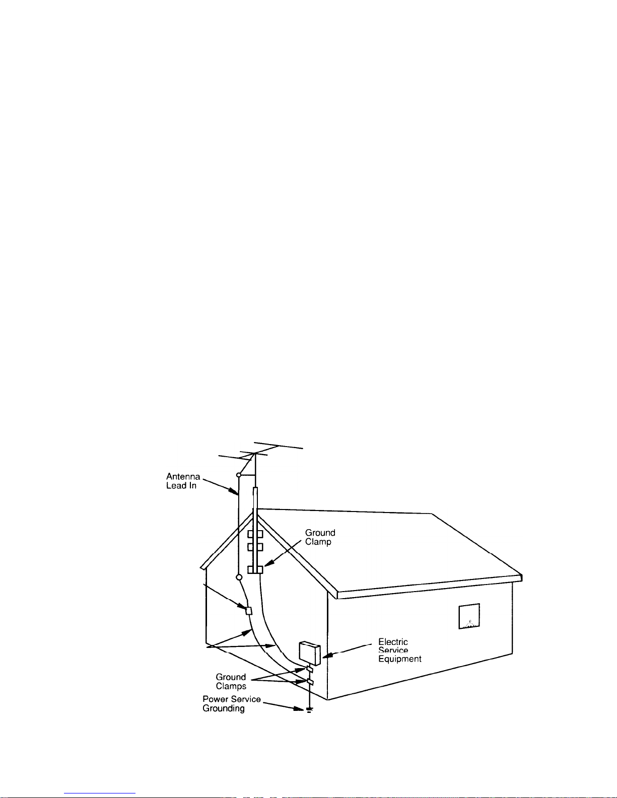
18. OUTDOOR ANTENNA GROUNDING
If an outside antenna is to be used with the Hafler Tuner, be sure that the antenna system is grounded so as to provide
some protection against voltage surges and built up static charges. Section 810 of the National Electrical Code, ANSI/
NFPA No. 70-l 984, provides information concerning supporting structure, grounding of the lead-in wires to an antenna
discharge unit, size of grounding conductors, location of antenna discharge unit, connections to grounding electrodes, and
requirements for the grounding electrode. See Figure 1.
FIGURE 1
Wire
Antenna
Discharge Unit
(NEC Section 81 O-20)
Grounding Conductors
(NEC Section 81 O-21 )
/,,“;
Electrode Svstem =
(NEC Art
250,
Part H)
-2-

TABLE OF CONTENTS
PERFORMANCE SPECIFICATIONS
...............................................................................................
4
General Information ..................................................................................................................
5
INSTALLATION
Rackmounting ............................................................................................................................
5
Ventilation/Placement ................................................................................................................
5
Line Voltage ...............................................................................................................................
5
OPERATION/CONNECTIONS
Power Cord Connection ............................................................................................................
5
Convenience Outlets ................................................................................................................
5
Front Panel ViewDiagram ........................................................................................................
6
Rear Panel View Diagram
........................................................................................................
8
Remote Control Diagram .........................................................................................................
10
Functional Block Diagram ........................................................................................................
11
Antenna Connections .............................................................................................................
12
Initial Power-Up/Muting System ..............................................................................................
12
Preamplifier Section
Audio Line Level Inputs ..........................................................................................................
12
Video Switching ......................................................................................................................
12
Tape Inputs and Outputs .........................................................................................................
13
Tone Controls and Tone In/Out .............................................................................................. 13
Mute Control ............................................................................................................................
14
Volume Control and Volume Control Indicator ........................................................................
14
Balance Control .......................................................................................................................
14
Mono Control ...........................................................................................................................
14
Headphone Output ................................................................................................................. 14
AM/FM Tuner Section
AM/FM Selector ................................................................................................................................
14
Up/Down Tuning and Auto Selector ....................................................................................... 15
Memory Presets
l-9 and +10
Preset Shift (Front Panel) ........................................................
15
Memory Preset Buttons
'1', ’
1 1'
and Next (Remote Control) .................................................. 15
Storing Stations into Memory..
................................................................................................
15
Mono Control ...........................................................................................................................
15
CIRCUIT DESCRIPTION
Line Level Input Selector System .........................................................................................
16
JFET Buffer And Record Output Driver
..................................................................................
16
Tape Monitor Switching .......................................................................................................... 16
Volume And Balance Controls ..............................................................................................
16
Line Amplifier
...........................................................................................................................
16
Tone Control System ..............................................................................................................
16
Muting System
........................................................................................................................
16
Headphone Amplifier ..............................................................................................................
17
AM/FM Tuner ...........................................................................................................................
17
ADDITIONAL INFORMATION
General Troubleshooting Hints ...............................................................................................
17
Ground Loops ..........................................................................................................................
17
FM Antenna .............................................................................................................................
18
AM Antenna .............................................................................................................................
19
Remote Control Battery Replacement ....................................................................................
19
Cleaning/Maintenance ............................................................................................................
19
SERVICE POLICY AND LIMITED WARRANTY
.............................................................................
19
-3-
PERFORMANCE SPECIFICATIONS
LINE AMPLIFIER
(Measured at
Line Out)
HEADPHONE
AMPLIFIER
TUNER
SECTION-FM
TUNER
SECTION-AM
GENERAL
INFORMATION
All specifications are for 20 Hz - 20
kHz
unless specified otherwise.
FREQUENCY RESPONSE:
+O.l dB (into 33,000 ohms)
BANDWIDTH: 10 Hz
-
150 kHz, -3 dB, into 1 Ok ohm load
MAXIMUM OUTPUT: 5 volts RMS
TOTAL HARMONIC DISTORTION AND NOISE: 0.02% @ 2 volts RMS
SEI\ISITIVITY
(For 0.5 volts RMS Output): 45 mV RMS
SIGNAL TO NOISE RATIO (A-Weighted, relative to 2 volts RMS output): -100
dB
INPUT IMPEDANCE: 22k ohms
OUTPUT IMPEDANCE: 316 ohms
TONE CONTROLS: Bass:
fl6 dB
@ 20 Hz, moving inflection, variable turnover
Treble:
+14 dB
@ 20 kHz, shelving @ 5 kHz, fixed turnover
MAXIMUM OUTPUT: 4 volts RMS into 150 ohm load
OUTPUT IMPEDANCE: 150 ohms
IHF (USABLE) SENSITIVITY: Mono: 6.5
dBf,
Stereo: 12 dBf
SIGNAL STRENGTH FOR 50
dB
QUIETING: Mono: 11
dBf,
Stereo: 34.5 dBf
CAPTURE RATIO: 1.5
dB
AM SUPPRESSION: 60
dB
ALTERNATE CHANNEL SELECTIVITY: 63
dB
TOTAL HARMONIC DISTORTION AND NOISE @ 1 kHz: Mono: 0.08%, Stereo: 0.3%
SEPARATION: 40
dB
@ 1
kHz
SIGNAL TO NOISE RATIO @ 65
dBf:
Mono: 75 dB, Stereo: 70
dB
SENSITIVITY: 350 uV/m
SELECTIVITY: 27
dB
SIGNAL TO NOISE RATIO: 60
dB
AUDIO INPUTS: Tape 1, Tape 2/EPL,
AV1,
AV2, AV3, CD
AUDIO OUTPUTS: Line Out, Record
1,
Record 2/EPL, AV, Headphone
VIDEO INPUTS: Video
1,
Video 2, Video 3
VIDEO OUTPUTS: Monitor, Record
FRONT PANEL CONTROLS: Power, Tuner Memory Presets, Tuner Preset Shift, AM/FM Selector,
Tuner Memory, Mono, Tone In, Volume, Balance, Bass, Treble, Tuner Auto/Manual, Up/Down Tuning,
Tape 1, Tape 2/EPL, Audio/Video Input Selectors.
-4-

REMOTE CONTROLS: Up/Down Volume, Up/Down Tuning, Preset Next, Preset ‘1 ‘, Preset ‘11’: Audio/
Video Input Selectors, Tape 1, Tape
2/EPL,
Power, AM/FM Selector, Tone In, Mute.
CONVENIENCE OUTLETS:
120 VAC MODELS: 1 Polarized Unswitched, 2 Polarized Switched, 1 Grounded Switched
240 VAC MODELS: 1 Reverse-IEC Unswitched, 2 Reverse-IEC Switched
PHYSICAL DIMENSIONS:
17” Wide x
l l-3/5”
Deep x
2-l/2”
High (excluding feet); Faceplate 17” or 19” Wide
43.2 cm Wide x 29.5 cm Deep x 6.3 cm High (excluding feet); Faceplate 43.2 cm or 48.3 Wide
1
POWER CONSUMPTION (Excluding Convenience Outlets): 20 watts Max.
INSTALLATION
RACKMOUNTING
VENTILATION/
PLACEMENT
LINE
VOLTAGE
The 945
Preamp/Tuner
is supplied in either a 17” Black Version, or a 19” Silver Version. The 19” model
has rackmounting holes provided for installation in equipment racks. The holes are on standard EIA
spacings, though the faceplate height is not standard EIA size.
The 945 produces very little heat during operation, and therefore requires no special considerations for
ventilation. The
preamp/tuner
should be located at least several inches away from components that
contain large power transformers (such as power amplifiers), due to the possibility of audible hum or buzz
from magnetic radiation.
The 945
Preamp/Tuner
is available in either 120 VAC or 240 VAC,
50/60
Hz versions . Make sure that
the unit is configured for your local AC line voltage before attempted use. The configuration is labelled
directly above the power cord entry point.
OPERATION/CONNECTIONS
POWER CORD
CONNECTION
CONVENIENCE
OUTLETS
Units wired
for 240
VAC are supplied without AC power cords. Local agents will supply cords with male
connectors appropriate to the local standard.
Units wired for 120 VAC are supplied with a detachable AC power cord. The female connector plugs
into the receptacle provided on the rear panel. This power cord is a standard IEC Type
320, 3-wire,
16
gauge assembly. Should replacement ever be necessary, be sure to replace it with an identical cord.
Never remove the grounding pin from the male end of the cord. In applications where a grounded wall
outlet is not available, a ground adaptor should be employed, with the ground tab or wire of the adaptor
connected to a suitable earth ground.
Units wired for 720 VAC have a total of four outlets for connection of associated components. The
polarized Unswitched Outlet is powered at all times, which should generally be used for a turntable or
tape deck. The remaining three Switched Outlets (one grounded, two polarized) are powered when the
Power Switch is engaged, as indicated by the switch’s green light. The grounded outlet is provided for
equipment requiring a grounded connection.
Units wired for 240 VAC have a total of three reverse-IEC outlets for connection of associated components. The Unswitched Outlet is powered at all times, which should generally be used for a turntable
or tape deck. The remaining two Switched Outlets are powered when the Power Switch is engaged, as
indicated by the switch’s green light.
for
all
models, the maximum power available from the Unswitched Outlet is 200 watts. The maximum
total power available from the Switched Outlets is 800 watts. This total power may be drawn from a single
outlet, or a combination of outlets. Since some power amplifiers consume more than 800 watts at
maximum output, check the power amplifier’s rating before connecting to these convenience outlets.
-5-
 Loading...