

DC
POWER
SUPPLY
Tenma Models 72-2005 and 72-6535
(Analog and Digital
Series)
User
Manual
CONTENTS
SECTION PAGE
1
. INTRODUCTION
.............................................................................................................................
1
......................................................................................................................
2
.
SPECIFICATIONS
2
2-
General
............................................................................................................................
2
2-2
Constant Voltage Operation
..................................................................................................
3
2-3
Constant Current Operation
...................................................................................................
3
....................................................................................................................
2-4
Indicator Meter
3
2-5
Insulation
.........................................................................................................................
4
...........................................................................................................
3
.
THEORY OF OPERATION
4
.
PANEL CONTROLS AND INDICATORS
...........................................................................................
4-1
Front Panel
..........................................................................................................................
4-2
Rear Panel
..........................................................................................................................
5
OPERATION INSTRUCTIONS
......................................................................................................
5-1
Precaution
.........................................................................................................................
............................................................................................................
5-2
Setting Current Limit
5-3
Constant Voltage/Constant Current Characteristic
......................................................................
...................................................................................................................
5-4
Operation Mode
.............................................................................................................................
6
MAINTANCE
6-1
Fuse Replacement
.............................................................................................................
6-2
Line Voltage Conversion
.......................................................................................................
6-3
Adjustments
.........................................................................................................................
.............................................................................................................................
6-4
Cleaning
1
.
INTRODUCTION
The regulated DC power supply have been designed to provide the most often required in the laboratory. schools and
production Lines
.
The output voltage is continuously adjustable between 0 to rating voltage in one range by means of a coarse and fine
potentiometer
.
the load current may have any value from 0 rating current and adjusted by means of a coarse and fine potentiometer
.
Both output can accurately readson voltmeter and ammeter .
Both stability and ripple are extremely good to meet the requirements of modern circuit design . The unit can be used as either
constant voltage or current source
. 'The various operation mode are described in more detail in the Operation Instruction section
.
For applications when output'greater than V or A is need. the unit can be connected up in series or parallel .
For
applicati~n in audio production lines. the continuous or dynamic load internal selectable
.

2.
SPECIFICATIONS
2-1
General
Main supply
100V/120Vl220V/240V *lo% 50160
Hz
(Switch selectable)
Rating, dimension and weight see Table
2-1.
Table
2-1
MODEL
GPS-1830
GPS-1830D
GPS-1850
GPS-1850D
GPS-3030
G PS
-
3030D
GPS
-
6010
Weight
Kg
4.0
4.0
5.5
5.5
5.0
5.0
4.0
FUSE
Type and Rating
WARNING.
Voltages more than
60V
DC are a lethal shock hazard to the user.
Be careful when connecting power supplies in series to achieve voltages higher
than
60V
DC total or
60V
DC between any connection and earth ground.
Dimensions
:
128
(W)
X
145
(H)
X
285 (D)
rnrn
1 00v1120v
1
T
2A 250V
T
2A 250V
T
2.5A 250V
T
2.5A 250V
T
2.5A 250V
T
2.5A 250V
T
2A 250V
Operation mode
Single or Tracking (Series or Parallel) operation (two units).
Max. Rating
22OVl24OV
T
1A 250V
T
1A 250V
T
1.25A 250V
T
1.25A 250V
T
1.25A 250V
T
1.25A 250V
T
1A 250V
Operation Environment : Indoor use
Altitude up to
2000
m
Installation Category
IT
Pollution degree
2
Input Rating
Volts
(V)
18
18
18
18
30
30
60
Watts
120
120
190
190
160
160
120
Amps
(A)
3
3
5
5
3
3
1
VA
150
150
230
230
200
200
150
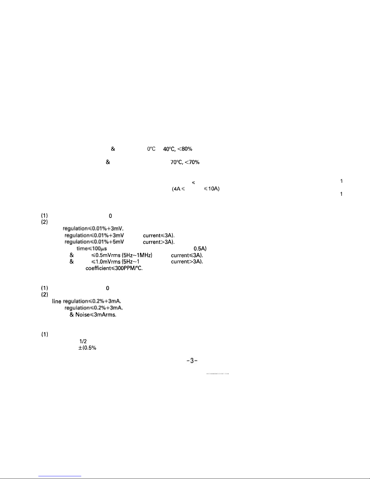
Operation Temperature
&
O"C
to 40°C, <80%
Humidity
Storage Temperature
&
-
10°C to 70"C, <70%
Humidity
Accessories
.......................................................................................
Test
Lead
(current < 4A)
1
(4AS current SIOA)
..................................................................................................
Operation Manual
1
2-2
Constant Voltage Operation
(1) Output voltage ranges 0 to rating voltage continuously adjustable.
(2) Voltage regulation
line
regulation<O.O1%+3mV.
load regulation~O.O1%+3mV (rating current~3A).
load regulation~O.O1%+5mV (rating current>3A).
(3) Recovery time<IOOps (50% Load change, minimum load 0.5A)
(4)
Ripple & Noise ~0.5mVrms (5Hz-1MHz) (rating current~3A).
Ripple & Noise <l.OmVrms (5Hz-1 MHz) (rating current>3A).
(5)
Temperature coefficient~300PPMPC.
2-3
Constant Current Operation
(1) Output current range 0 to rating current continuously adjustable.
(2) Current regulation
line regulation60,2%+3mA.
load regulation<0.2%+3mA.
(3) Ripple & NoiseS3mArms.
24
Indicator Meter
(1) Digital Type
Display: 3
112 Digits 0.5" Red
LED
DISPLAY (Voltage and current switchable).
Accuracy:
+(0.5%
of
rdg + 2 digits).
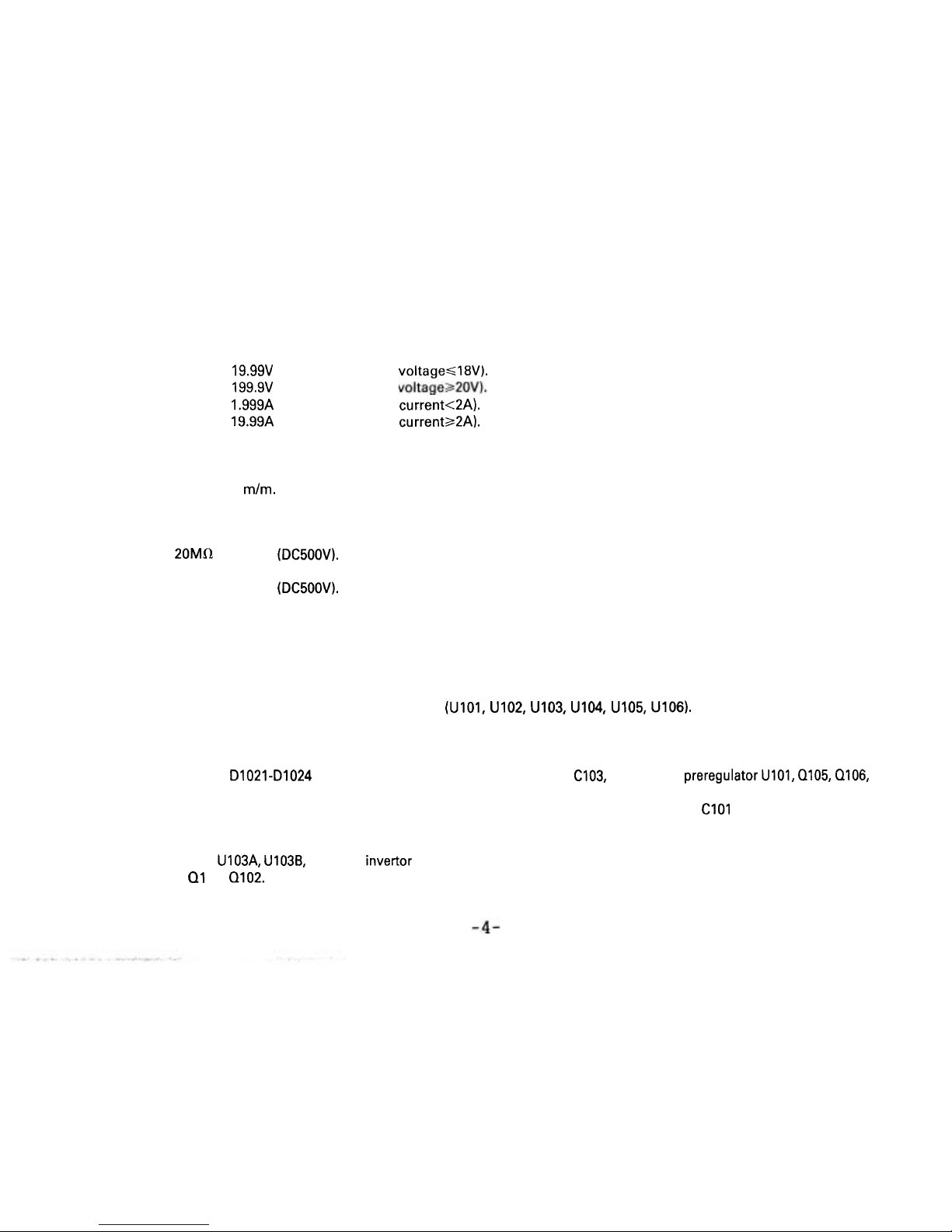
Voltage range:
19.99V of full scale (rating voltage618V).
199.9V of full scale (rating voltage>20V).
Current range:
1.999A of full scale (rating current<2A).
19.99A of full scale (rating currenta2A).
(2) Analog Type
Meter: Voltmeter and Ammeter each one.
Class: 2.5
Dimensions: 50x50
m/m.
2-5
Insulation
Between chassis and output terminal.
20MIR or above (DC500V).
Between chassis and AC cord.
30MR or above
(DC500V).
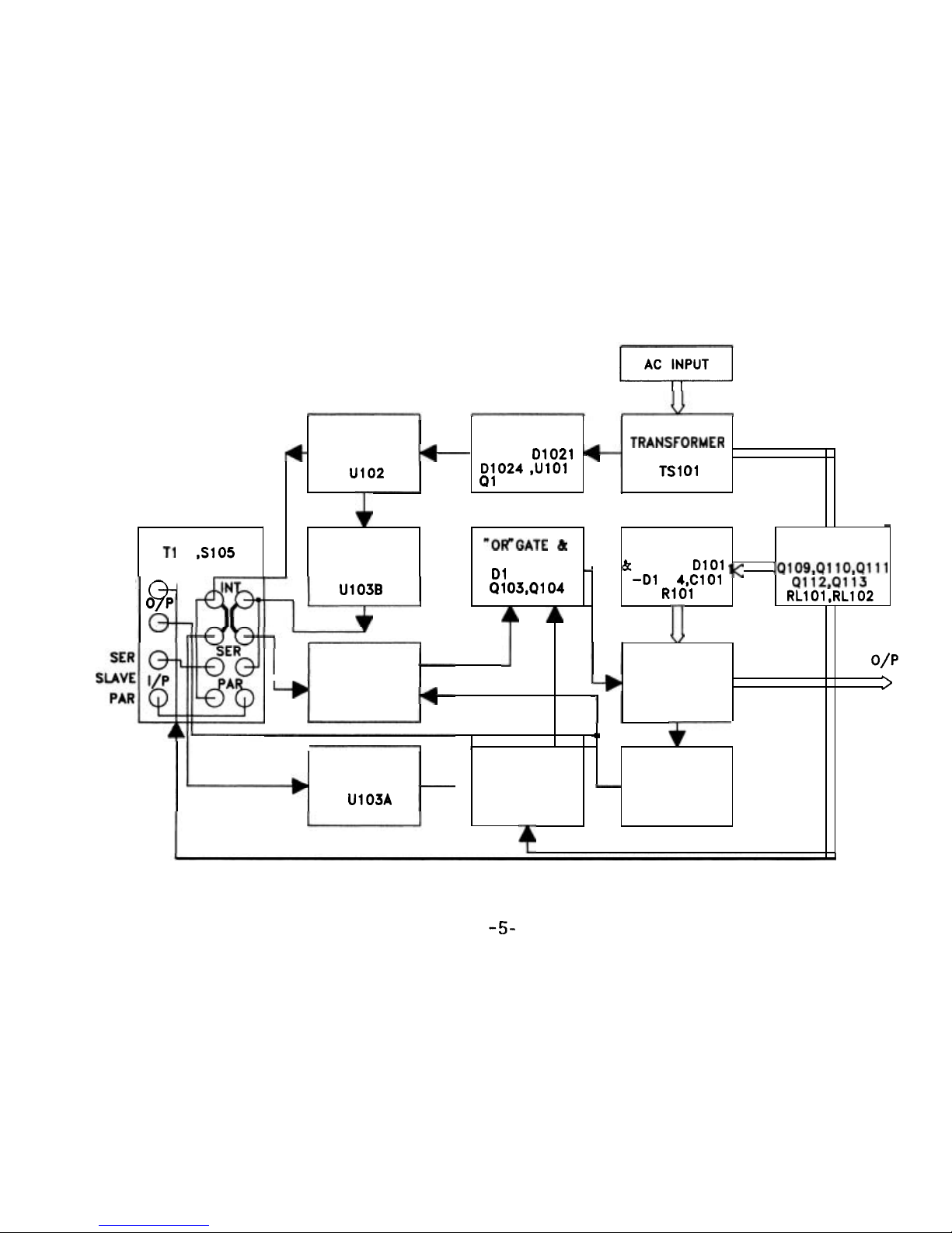
3.
THEORY
OF
OPERATION
The power supply consists of an AC input circuit and transformer, a bias supply consisting of a rectifier and filter and reference
voltage source, a main regulator circuit consisting of the main rectifier and filter, a series regulator, a current comparator, a voltage
comparator, a reference voltage amplifier, a remote control and a relay control circuit.
The circuit element are several of integrated circuit
(U101, U102, U103, U104, U105, U106).
The circuit arrangement is shown in block diagram from Fig. 1.
The circuit is discussed with reference to the block diagram Function Description.
Single phase input power is applied to transformer through the input circuit.
Auxiliary rectifier
D1021-Dl024 provides a bias voltage filtered by capacitor C103, C104 for the preregulator U101, Q105, Q106,
that provides a regulator voltage for element of action.
The main rectifier, a full wave bridge rectifier, provides the power which is filtered by capacitor
C101 and then regulated via
a series regulator and deliver to the output.
U105 acted as a current limiter. When current is over predominante rating, it acted and decreased the current U102 provides
a reference voltage for
U103A, U1038, U103 is a invertor amplifier, U105 is a current comparator. Both via
OR
gate and driver amplifier
to series control
01 01, Q102.
The relay control circuit provides limited power dissipation is series regulator.
AC INPUT
I
Fig.
1
Block
Diagram
-5-
REFERENCE
VOLTAGE
SOURCE
U102
AUXILIARY
RECTIFIER AND
FILTER
Dl021
Dl024 ,UlOl
91 05.91
06
REMOTE CONTROL
TI 01 ,S105
TRANsFoRMER
TSl 01
,
V
>
R
EFE
R
E
N
C
E
CURRENT
SER
@-
U103B
MAIN
RECTIFIER
&
FILTER Dl01
-01 01 4,ClOl
01 03,4104
*OR"GATE
&
DRIVER AMP
Qll2,Qll3
MASTER
O/P
-
R101
I<
COMPARATOR
RL101 ,RL102
RELAY
CONTROL
.Q109,0110,Q111
Dl 08,0109
PAR
C
A
o/p
>
CURRENT
-+
COMPARATOR
U105
I
SERIES
REGULATOR
9101,9102
4
b
CURRENT
REFERENCE
VOLTAGE
AMPLIFIER
U103A
-
COMPARATOR
U104
SENSER
AMPLIFIER
U106
 Loading...