

Page 1

Programmable DC Power Supply
GPP-1326/GPP-2323/GPP-3323/GPP-4323
User Manual
GW INSTEK PART NO. 82PP343230ED1
ISO-9001 CERTIFIED MANUFACTURER
Page 2

Copyright Statement
This manual contains proprietary information, which is protected by
copyright. All rights are reserved. No part of this manual may be
photocopied, reproduced or translated to another language without
prior written consent of Good Will company.
The information in this manual was correct at the time of printing.
However, Good Will continues to improve products and reserves the
rights to change specification, equipment, and maintenance
procedures at any time without notice.
Good Will Instrument Co., Ltd.
No. 7-1, Jhongsing Rd., Tucheng Dist., New Taipei City 236, Taiwan.
Page 3

Table of Contents
Table of Contents
SAFETY INSTRUCTIONS .................................................. 6
Safety Symbols ........................................................... 6
Safety Guidelines ....................................................... 7
Power cord for the United Kingdom ......................... 10
OVERVIEW .................................................................... 11
Introduction ............................................................. 12
Key Features ............................................................ 15
Front Panel .............................................................. 17
Rear Panel................................................................ 24
Constant Voltage/Constant Current Crossover
Characteristics ......................................................... 26
GETTING STARTED ........................................................ 27
Start Up ................................................................... 28
Load Connection ...................................................... 29
Turning the Output On/Off ...................................... 31
BASIC OPERATION ........................................................ 32
Display Change ........................................................ 33
Source Function ....................................................... 36
Independent Output Mode ..................................... 41
Tracking Series and Tracking Parallel Modes ......... 42
Load Function .......................................................... 46
Sequence Function ................................................... 50
Set Sequence Output ............................................... 50
Set Group Parameter ............................................... 52
Construct Templet ................................................... 54
Menu Tree ................................................................ 57
Save and Recall ........................................................ 59
3
Page 4

GPP Series User Manual
Delay Function ......................................................... 62
Set Delay Output ..................................................... 62
Set Group Parameter ............................................... 65
Menu Tree ................................................................ 68
Save and Recall ........................................................ 70
Monitor Function ..................................................... 72
Set Monitor .............................................................. 73
Recorder Function .................................................... 75
Set Recorder ............................................................. 76
Enternal I/O Control ................................................ 79
Key Function Description ........................................ 81
FILE OPERATION ........................................................... 83
Save/Recall .............................................................. 84
Restore Factory Default Settings .............................. 87
SYSTEM SETTINGS ........................................................ 88
System Information ................................................. 89
System Settings ....................................................... 90
Firmware Upgrading ................................................ 92
Description of Using Flash Drive ............................. 93
REMOTE CONTROL ....................................................... 95
Connection Usage .................................................... 97
RS-232 ...................................................................... 98
USB .......................................................................... 99
GPIB ......................................................................... 101
LAN .......................................................................... 102
Command Syntax ................................................... 108
Command List ....................................................... 112
Measurement Instructions ...................................... 112
Display Functions .................................................... 112
4
Page 5

Table of Contents
Output Commands ................................................. 112
Source and Load Commands .................................. 113
Status Commands ................................................... 118
System Commands ................................................. 119
System Related Commands .................................... 120
IEEE488.2 Common Commands ............................ 120
Command Details .................................................. 121
Measurement Commands ...................................... 121
Display Commands ................................................. 123
Output Commands ................................................. 125
Source and Load Commands ............................... 129
Status Commands ................................................... 170
System Commands ................................................. 176
System Related Commands .................................... 185
SCPI Status Registers SCPI .................................... 186
Event Registers ........................................................ 188
Enable Registers ...................................................... 188
Status Byte Register ................................................. 188
Standard Event Register .......................................... 190
Status Byte Register Commands............................. 191
Standard Event Register Commands ...................... 192
Other Status Register Commands .......................... 194
Errors ..................................................................... 195
Error Message .......................................................... 195
Command Errors ..................................................... 195
APPENDIX .................................................................... 199
Replacing the Fuse ................................................. 199
Specifications ........................................................ 200
Optional Accessories ............................................. 203
Declaration of Conformity ...................................... 204
5
Page 6

GPP Series User Manual
WARNING
Warning: Identifies conditions or practices that
could result in injury or loss of life.
CAUTION
Caution: Identifies conditions or practices that
could result in damage to the GPP or to other
properties.
DANGER High Voltage
Attention Refer to the Manual
Protective Conductor Terminal
Earth (ground) Terminal
Do not dispose electronic equipment as
unsorted municipal waste. Please use a
separate collection facility or contact the
supplier from which this instrument was
purchased.
SAFETY INSTRUCTIONS
This chapter contains important safety
instructions that you must follow during
operation and storage. Read the following before
any operation to insure your safety and to keep
the instrument in the best possible condition.
Safety Symbols
These symbols may appear in the manual or on the instrument.
6
Page 7

SAFETY INSTRUCTIONS
General
Guideline
CAUTION
Do not place any heavy object on the unit.
Avoid severe impact or rough handling that
leads to damaging the unit.
Do not discharge static electricity to the unit.
Do not block the cooling fan opening.
Do not perform measurements on circuits that
are directly connected to mains power.
Do not disassemble the GPP unless you are
qualified.
(Measurement categories) EN 61010-1:2010
specifies the measurement categories and their
requirements as follows. The GPP Series falls
under category I.
Measurement category IV is for measurement
performed at the source of low-voltage
installation.
Measurement category III is for measurement
performed in the building installation.
Measurement category II is for measurement
performed on the circuits directly connected to
the low voltage installation.
Measurement category I is for measurements
performed on circuits not directly connected to
Mains.
Power Supply
WARNING
AC Input voltage range:
100V/120V/220V/230V ±10%
Frequency: 50Hz/60Hz
To avoid electrical shock connect the protective
grounding conductor of the AC power cord to
an earth ground.
Safety Guidelines
7
Page 8

GPP Series User Manual
Fuse
WARNING
Fuse type: 100V/120V:T6.3A/250V,
220V/230V:T3.15A/250V
To prevent fire, replace the fuse only with the
specified type and rating.
Disconnect the power cord before replacing the
fuse.
Make sure the cause of fuse blowout is fixed
before replacing the fuse.
Cleaning the
power supply
Disconnect the power cord before cleaning the
oscilloscope.
Use a soft cloth dampened in a solution of mild
detergent and water. Do not spray any liquid
into the oscilloscope.
Do not use chemicals containing harsh products
such as benzene, toluene, xylene, and acetone.
Operation
Environment
Location: Indoor, no direct sunlight, dust free,
almost non-conductive pollution (Note below)
Relative Humidity: < 80%
Altitude: < 2000m
Temperature: 0°C to 40°C
8
Page 9

SAFETY INSTRUCTIONS
(Pollution Degree) EN 61010-1:2010 specifies
pollution degrees and their requirements as
follows. The GPP Series falls under degree 2.
Pollution refers to “addition of foreign matter,
solid, liquid, or gaseous (ionized gases), that
may produce a reduction of dielectric strength
or surface resistivity”.
Pollution degree 1: No pollution or only dry,
non-conductive pollution occurs. The pollution
has no influence.
Pollution degree 2: Normally only non-
conductive pollution occurs. Occasionally,
however, a temporary conductivity caused by
condensation must be expected.
Pollution degree 3: Conductive pollution
occurs, or dry, non-conductive pollution occurs
which becomes conductive due to condensation
which is expected. In such conditions,
equipment is normally protected against
exposure to direct sunlight, precipitation, and
full wind pressure, but neither temperature nor
humidity is controlled.
Storage
environment
Location: Indoor
Relative Humidity: < 70%
Temperature: -10°C to 70°C
9
Page 10

GPP Series User Manual
Green/ Yellow:
Earth
Blue:
Neutral
Brown:
Live (Phase)
Power cord for the United Kingdom
When using the power supply in the United Kingdom, make sure
the power cord meets the following safety instructions.
NOTE: This lead/appliance must only be wired by competent persons
WARNING: THIS APPLIANCE MUST BE EARTHED
IMPORTANT: The wires in this lead are coloured in accordance with the
following code:
As the colours of the wires in main leads may not correspond with
the coloured marking identified in your plug/appliance, proceed as
follows:
The wire which is coloured Green & Yellow must be connected to
the Earth terminal marked with either the letter E, the earth symbol
or coloured Green/Green & Yellow.
The wire which is coloured Blue must be connected to the terminal
which is marked with the letter N or coloured Blue or Black.
The wire which is coloured Brown must be connected to the
terminal marked with the letter L or P or coloured Brown or Red.
If in doubt, consult the instructions provided with the equipment or
contact the supplier.
This cable/appliance should be protected by a suitably rated and
approved HBC mains fuse: refer to the rating information on the
equipment and/or user instructions for details. As a guide, a cable
of 0.75mm2 should be protected by a 3A or 5A fuse. Larger
conductors would normally require 13A types, depending on the
connection method used.
Any exposed wiring from a cable, plug or connection that is
engaged in a live socket is extremely hazardous. If a cable or plug is
deemed hazardous, turn off the mains power and remove the cable,
any fuses and fuse assemblies. All hazardous wiring must be
immediately destroyed and replaced in accordance to the above
standard.
10
Page 11

OVERVIEW
OVERVIEW
This chapter contains a brief introduction to GPP
series including the main features and an
overview of the front and rear panel. Use the
Getting Started chapter on page 27 to start up
instructions and how to setup the appropriate
operation environment.
Introduction ............................................................. 12
Key Features ............................................................ 15
Front Panel .............................................................. 17
Rear Panel................................................................ 24
Constant Voltage/Constant Current Crossover
Characteristics ......................................................... 26
11
Page 12

GPP Series User Manual
Overview
The GPP series regulated DC power supply
series are light weight, adjustable,
multifunctional work stations. The GPP-1326
has a 1 independent adjustable voltage outputs
with sense.The GPP-2323 has a 2 independent
adjustable voltage outputs. The GPP-3323 three
independent outputs: two with adjustable
voltage levels and one with fixed level
selectable from 1.8V, 2.5V, 3.3V and 5V. The
GPP-4323 has four independent voltage
outputs that are all fully adjustable.
The GPP series can be used for logic circuits
where various output voltage or current are
needed, and for tracking mode definition
systems where plus and minus voltages with
insignificant error are required.
Independent /
Tracking Series /
Tracking Parallel
The three output modes of GPP series,
independent, tracking series, and tracking
parallel, can be selected through pressing the
TRACKING key on the front panel. In the
independent mode, the output voltage and
current of each channel are controlled
separately. The isolation degree, from output
terminal to chassis or from output terminal to
output terminal, is 500V.
In the tracking modes, both the CH1 and CH2
outputs are automatically connected in series
or parallel; no need to connect output leads. In
the series mode, the output voltage is doubled;
in the parallel mode, the output current is
doubled.
Introduction
12
Page 13

OVERVIEW
Load Mode
The GPP series models have additional Load
function on both CH1 & CH2 with 3 modes:
CV (Constanct Voltage), CC (Constant Current)
and CR (Constant Resistance), all of which can
be selected through the function keys on the
front panel. Voltage, current and resistance can
be well regulated in each mode, respectively.
Constant Voltage/
Constant Current
Each output channel is completely
transistorized and well-regulated, and works in
constant voltage (CV) or constant current (CC)
mode. Even at the maximum output current, a
fully rated, continuously adjustable output
voltage is provided. For a big load, the power
supply can be used as a CV source; while for a
small load, a CC source. When in the CV mode
(independent or tracking mode), output
current (overload or short circuit) can be
controlled via the front panel. When in the CC
mode (independent mode only), the maximum
(ceiling) output voltage can be controlled via
the front panel. The power supply will
automatically cross over from CV to CC
operation when the output current reaches the
target value. The power supply will
automatically cross over from CC to CV when
the output voltage reaches the target value. For
more details about CV/CC mode operation,
see page 26.
Automatic
tracking mode
The front panel display (CH1, CH2) shows the
output voltage or current. When operating in
the tracking mode, the power supply will
automatically connect to the auto- tracking
mode.
13
Page 14

GPP Series User Manual
Display Change
Function
The GPP series provides up to 7 display types,
each of which can be well selected via setting.
For details, see page 32.
Output Waveform
Function
Under Source mode of the GPP series, user can
customize a certain V/I sequential waveform
output. Under Load mode, it is programmable
for dynamic load (below 1Hz). For details, see
page 50.
Remote Control
To meet the various needs of customers, the
GPP is designed for USB, GPIB and LAN
remote control. For details, see page 95.
Additional
Function
Control signal of external switch is reserved for
user. For details, see page 79.
14
Page 15

OVERVIEW
Features
Multiple Outputs:
GPP-1326:32V/6A x 1
GPP-2323:32V/3A x 2 (CH1/CH2)
GPP-3323:32V/3A x 2 (CH1/CH2)
1.8V/2.5V/3.3V/5V/5A x 1 (CH3)
USB Port Output:3A
GPP-4323:32V/3A x 2 (CH1/CH2)
5V/1A x 1 (CH3),15V/1A x 1 (CH4)
Constant voltage and constant current operation
(CV/CC).
Low noise, thermostatically controlled fan.
Compact, lightweight, standard rack mount
comformity 3U, half Rack.
4.3 inch TFT display.
Key Features
15
Page 16

GPP Series User Manual
Operation
Digital panel control.
Output on/off control (ON/OFF), and each
channel can be controlled separately.
Digital voltage and current settings. (Key &
Encode)
10 groups of save/recall settings and 2 groups of
power-on settings.
10 groups of save/recall Sequence.
10 groups of save/recall Delay.
10 groups of save/recall Record.
CH1/CH2 workable in Load Mode
7 types display modes available with 5 contents
and 2 waveforms respectively
Input/Output terminal (Control I/O)
Alarm buzzer (BEEP).
Key lock function (LOCK).
Multiple remote control interfaces (standard:
RS232, USB; optional: GPIB, LAN)
Protection
Features
Overvoltage and overcurrent protection (OVP/
OCP)
Overtemperature protection (OTP).
Polarity Reverse Protection
Overload Protection (OPP in Load mode)
Interface
Remote Control RS-232 (standard)
USB remote control. (standard)
Control I/O (standard)
LAN remote control (optional)
GPIB & LAN remote control (optional)
16
Page 17
OVERVIEW
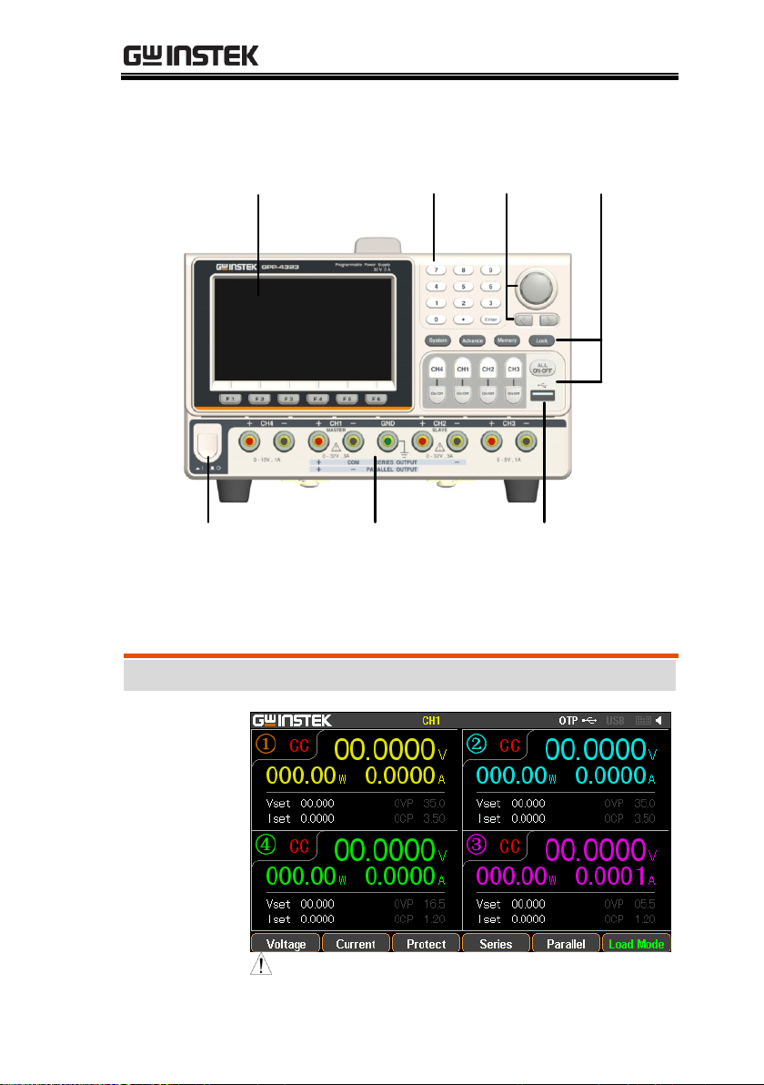
LCD
Number
pad
Scroll wheel/
Arrow keys
Function
keys
USB host
Front panel
output terminals
Power button
Display
Display
Interface
(Take GPP-4323 model as example)
Front Panel
*The panel above is the example of GPP-4323. For other models,
refer to page 23.
17
Page 18
GPP Series User Manual
Channel
distribution
Channel number and distribution vary by
models with different colors identifications:
CH1: Yellow CH2: Blue CH3: Pink CH4:
Green CH1 is master and CH2 becomes yellow
under tracking series and tracking parallel
modes.
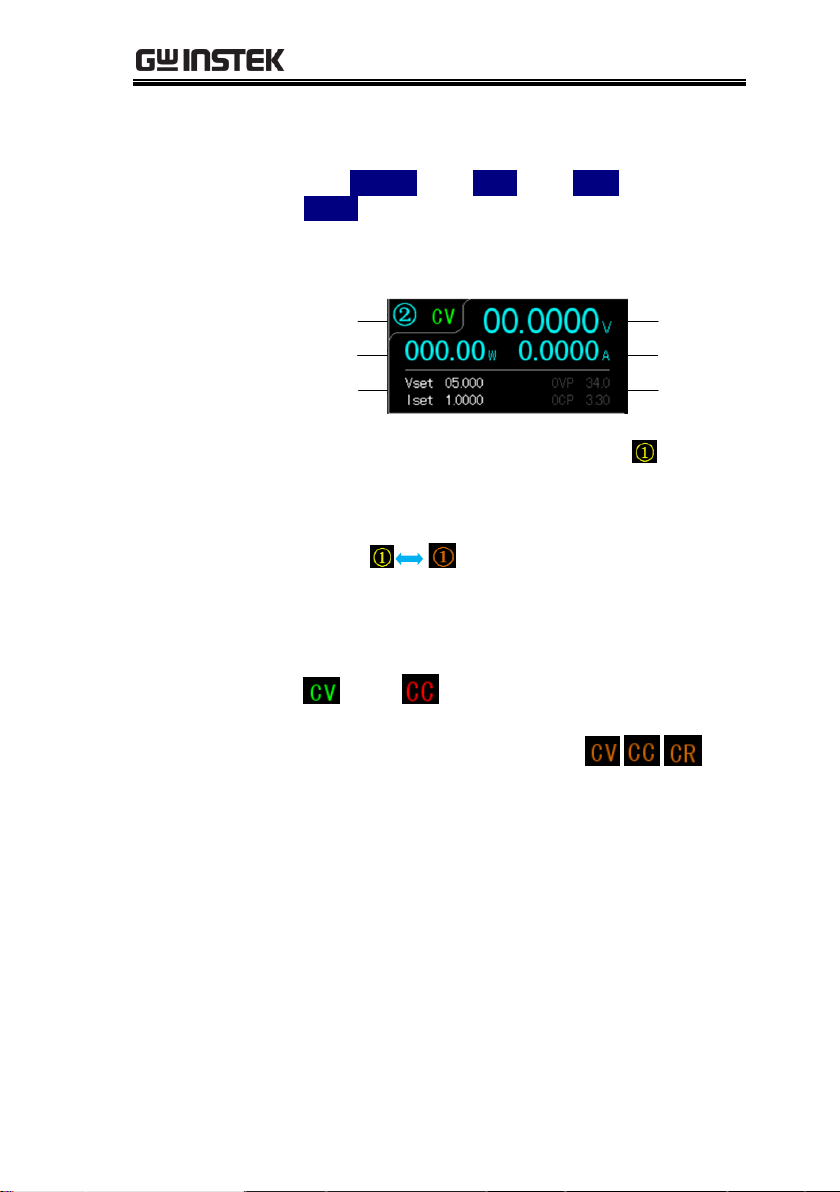
Single channel
display
Channel/
Status
Power
display
V/I
setting
Voltage
display
Current
display
OVP/OCP
setting area
Channel no.
Color of channel remains the origanl when
not in the state of setting.
Color of channel blinks between the original and
orange when being set.
Channel status
Display active channel state
Power supply: CH1/CH2/CH3/CH4: green
or red
Load Mode: CH1/CH2: orange
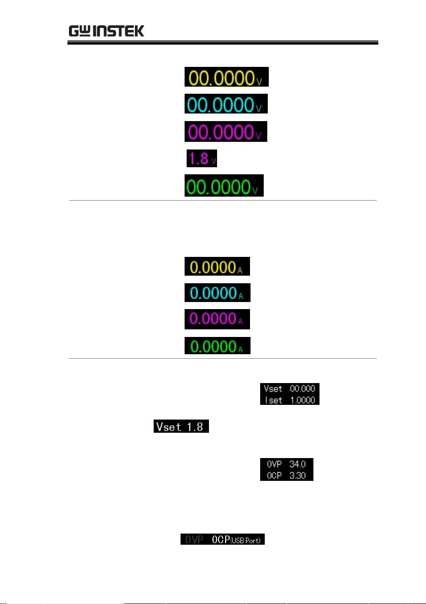
Voltmeter
Indicators
Displays the output voltage with up to 6 digits
of resolution. The default units are Volts (V).
18
Page 19
OVERVIEW
CH1:
CH2:
CH3: (GPP-4323)
(GPP-3323)
CH4:
Ammeter
Indicator
Displays the output current with up to 5 digits
of resolution. The default units are ampere (A).
CH1:
CH2:
CH3: (GPP-4323)
CH4:
Setting Display
Displays the voltage and current settings.
CH1/CH2/CH3/CH4:
CH3(GPP-3323) displays setting of voltage only
Display OVP/OCP settings
CH1/CH2/CH3/CH4:
The CH3 OVP of GPP-3323 is a fixed value
(approx. 5.5V), non-configurable and with only
on or off switch available for user. OCP is
available only for USB output port (approx.
3.1A)
19
Page 20
GPP Series User Manual
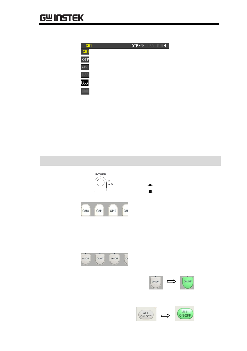
Status
Indicator
Display the set function/remote control interface
: The active channel under setting status
: The status of OTP protection mode
: The status of USB flash drive connected
: USB remotely disconnected
: USB remotely connected
: The status of control I/O connected
Others: when operating in the series/parallel
tracking mode, the corresponding SER/PAR icons
appear on the display.
when Sequence/Delay/Monitor/Recorder is
activated, the corresponding SEQ/DLY/MON/
REC icons appear on the display.
Function Keys
Power Button
Turns the power on or off.
On:
Off:
Channel select
buttons
Each channel has its own
button and promptly
switchable among CH1-CH4
setting.
Output buttons
Individual
output
The ON/OFF button is
operational individually by
each channel. The Output key
will light up when the output is
on.
ON:
Output all
All ON:
20
Page 21
OVERVIEW
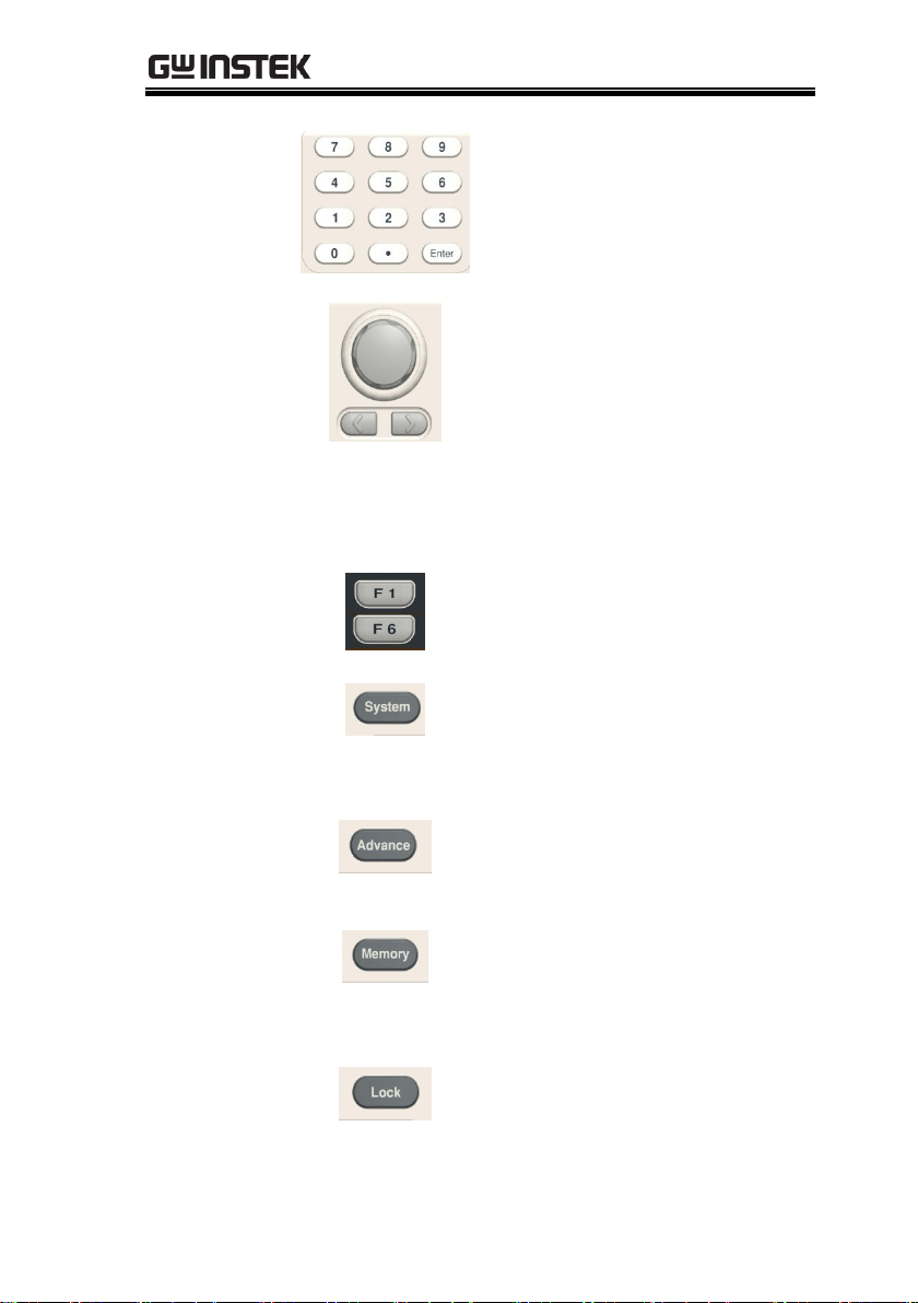
Number pad
For parameter value setting
Scroll wheel &
Arrow keys
Scroll wheel is used to set each
parameter value, whilst arrow
keys are used for parameter,
menu selection and
voltage/current fine
adjustment. It is used to switch
or operate the displayed
waveforms under diagram
display mode.
Function keys
The 6 function keys (F1-F6)
display varied functions per
different opertations.
System key
It is used to set functions
including Interface, Beep,
Backlight, etc. For details, refer
to page 90.
Advance key
It is used for certain advanced
functions like Sequence, Delay,
Monitor, Recorder, etc.
Memory key
It is used to operate several
functions including save and
recall, etc., for set parameters.
For details, refer to page 83.
Lock key
It is used to disable all the
panel keys except for the
Output key.
21
Page 22
GPP Series User Manual
Unlock
Press the F6 button to unlock,
which can disable remote
control and return to panel
operation.
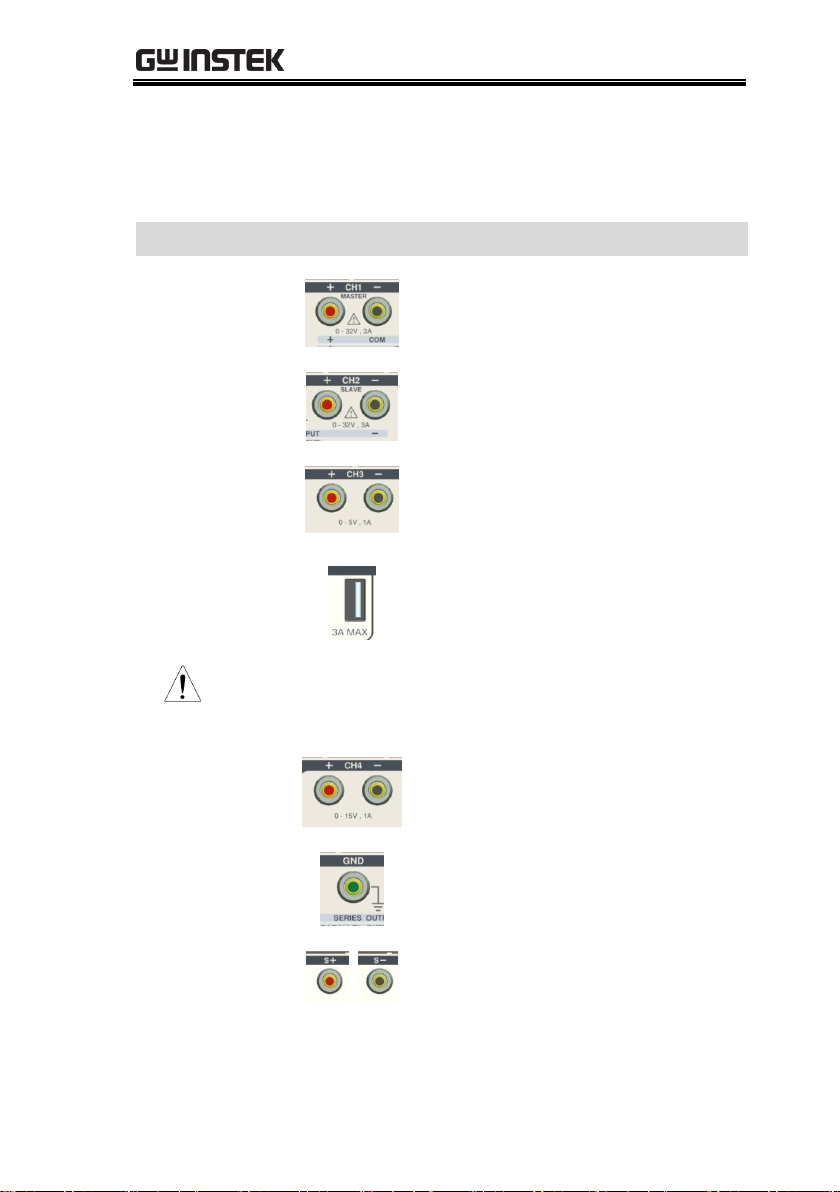
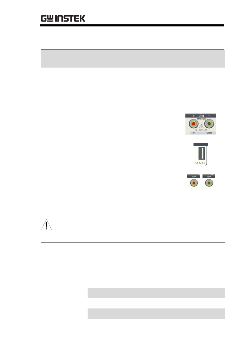
Terminals
CH1 terminal
Power output terminal or load
input terminal
CH2 terminal
Power output terminal or load
input terminal
CH3 terminal
Power output terminal
Power output terminal (GPP-
3323 only)
Warning: The output current from the 2 terminals should
Not exceed 5A for GPP-3323.
CH4 terminal
Power output terminal
GND terminal
Ground terminal
Voltage
feedback
terminal
(SENSE)
Sense terminal of power
output (1326 only)
22
Page 23
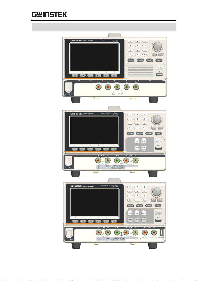
OVERVIEW
Panels of other models:
GPP-1326
GPP-2323
GPP-3323
23
Page 24
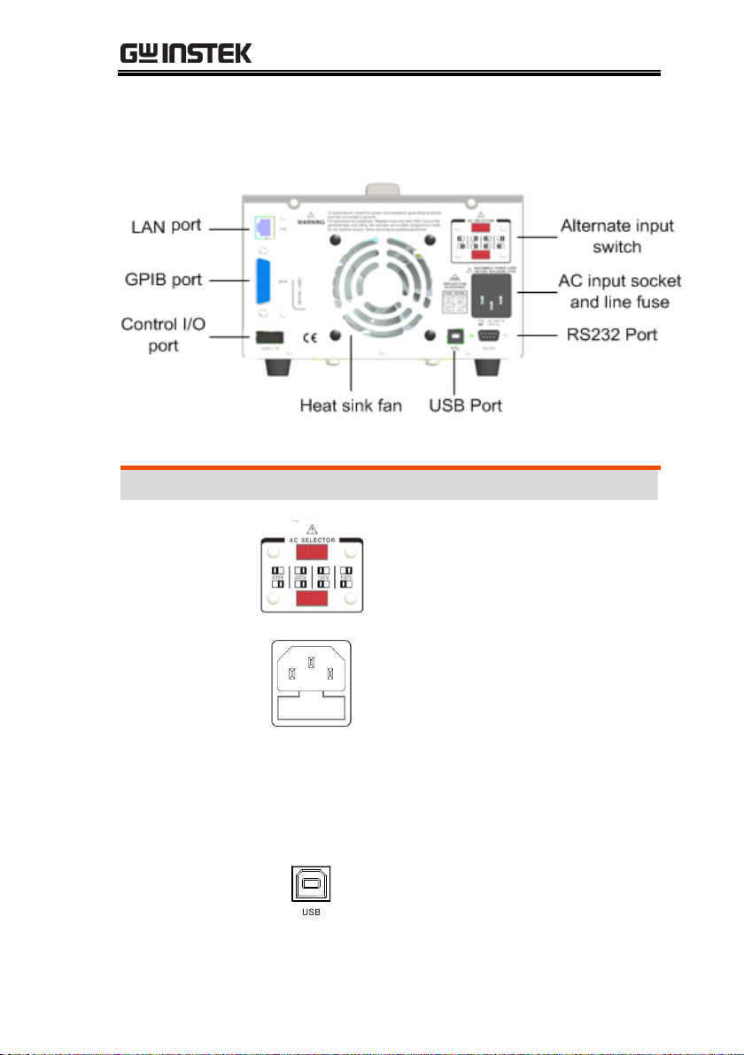
GPP Series User Manual
Terminals
Alternate
input switch
AC voltage selection:
100V/120V/220V/230V
±10%, frequency 50/60Hz
AC input
socket and
line fuse
The AC input accepts
100V/120V/220V/230V
AC. The frequency is
50Hz/60Hz.
Fuse:
100V/120V: T6.3A/250V,
220V/230V :T3.15A/250V,
slow-blow type, See page
199 for details.
USB port
USB device port for remote
control. See page 95 for
details.
Rear Panel
24
Page 25
OVERVIEW
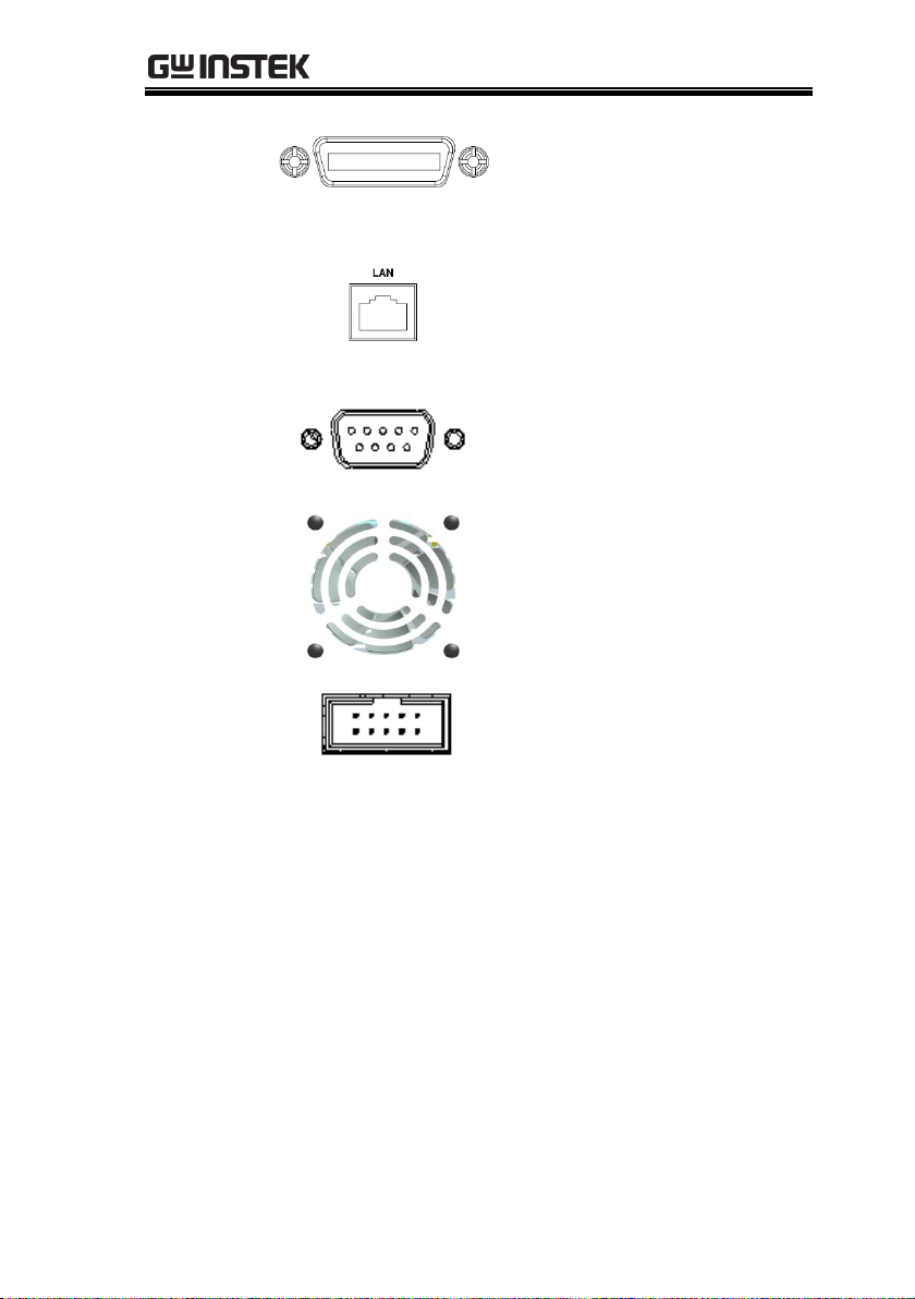
GPIB port
GPIB slave port for remote
control. Abides to
IEEE488.2 (SCPI) protocol.
See page 101 for details.
LAN port
LAN port for remote
control. See page 102 for
LAN setting and operation
details.
RS 232 port
RS232 port for remote
control. See page 98 for
details.
Heat sink
fan
Control I/O
port
5 ports in all for
input/output control. See
page 79 for details of
configuration.
25
Page 26

GPP Series User Manual
Background
The unit will switch automatically between
constant voltage and constant current
according to changes in the load.
CV mode
When the load current is less than the current
setting, the unit operates in constant voltage
mode, changing the current level according to
the load but maintaining the set voltage level
until the current reaches the set current level.
The status indicator will show CV on the LCD
when in CV mode.
Constant Current
Mode
When the output current reaches the set
current level, the unit switches operation to
constant current mode. The status indicator
will show CC on the LCD display. In CC mode,
the current level is maintained and the voltage
level is limited to less than the set voltage level
to limit the output power from an overload.
When the current drops below the set current
level, the unit will revert back to CV mode.
Diagram
Vmax
Imax
Constant
Voltage
Constant
Current
Vout
Iout
Constant Voltage/Constant Current
Crossover Characteristics
26
Page 27

GETTING STARTED
GETTING STARTED
This chapter describes the start up procedures and
the preparation that is necessary before operating
the power supply.
Start Up ................................................................... 28
Load Connection ...................................................... 29
Turning the Output On/Off ...................................... 31
27
Page 28

GPP Series User Manual
Checking the AC
Voltage
Before the power is turned
on, confirm that the input
power supply meets the
following conditions:
100V/120V/220V/230V
±10%,50/60Hz
Connecting the
AC power cord
The fuse is a slow-blow fuse.
3.15A(220V/230V)
6.30A(100V/120V),
Confirm that the fuse is of the
correct type and rating before
connecting the power cord.
Turning the
power on
Press the power button.
Turning the
power off
To turn the power off, press
the power button again.
Start Up
28
Page 29
GETTING STARTED
Recommended
Cables
Model
Specification
Usage
GTL-
104A
10A
Front panel terminal
GTL-105A
3A
Sense(1326 only)
Front panel
wiring
Use the GTL-104A cables for
the front panel source
connections.
USB Type A only
(Greater than 4A)
Use the GTL-105A cables for
the GPP-1326 sense
connections. Or connect + to
S+, - to S- terminal with a
short bar.
Caution
For safety considerations, please keep in mind
that the wiring must be equivalent to the wiring
on the front terminals.
Wire Gauge
Load wires must have enough current capacity
to minimize cable loss and load line impedance.
Voltage drop across a wire should not excess
0.5V. The following list is the wire current
rating at 450A/cm2.
Wire Size(AWG)
Maximum Current (A)
20
2.5 18
4
Load Connection
29
Page 30

GPP Series User Manual
16
6 14
10 12
16
30
Page 31

GETTING STARTED
Panel Operation
Press the Output key of
each channel
individually to turn the
output on. The Output
key will light-up when
the output is on.
When the output is
turned on, pressing the
Output key again will
turn the output off.
Press ALL ON/OFF key
when it needs to output
or turn off all channels
simultaneously (GPP-
1326 does not have this
button) .
Command Set
Refer to page 112 for more details on remote
commands chapter.
Automatic
Output Shut
Down
Any of the following actions will cause the
output to be automatically shut down:
Toggle between power output and load mode
Independent/Tracking Series/Tracking Parallel
operation
Recall the saved setting
OVP/ OCP/OPP/OTP protection is tripped.
When Sequence/Delay/Monitor/Control IO
fits the set conditions.
Turning the Output On/Off
31
Page 32

GPP Series User Manual
BASIC OPERATION
This chapter describes how to set various
functions.
Display Change ........................................................ 33
Source Function ....................................................... 36
Independent Output Mode ..................................... 41
Tracking Series and Tracking Parallel Modes ......... 42
Load Function .......................................................... 46
Sequence Function ................................................... 50
Set Sequence Output ............................................... 50
Set Group Parameter ............................................... 52
Construct Templet ................................................... 54
Menu Tree ................................................................ 57
Save and Recall ........................................................ 59
Delay Function ......................................................... 62
Set Delay Output ..................................................... 62
Set Group Parameter ............................................... 65
Menu Tree ................................................................ 68
Save and Recall ........................................................ 70
Monitor Function ..................................................... 72
Set Monitor .............................................................. 73
Recorder Function .................................................... 75
Set Recorder ............................................................. 76
Enternal I/O Control ................................................ 79
Key Function Description ........................................ 81
32
Page 33

BASIC OPERATION
Channel/Status
Work status
area
Read back
status area
Parameter
setting area
Function keys
display area
Warning
:
1. Under the Source interface:
Each channel has its own setting area
(V/I/OVP/OCP) and read back status area (V/I/W).
2. Under the Load interface:
It is basically equivalent to Sourece interface with
additional Load and OPP status displays.
Diverse display screens
In order to offer diverse information display of each channel to
meet requirements from different users, the GPP series provide
several selections of different display screens as follows:
Display Change
Display Area
33
Page 34

GPP Series User Manual
Type
GPP-1326
GPP-2323
GPP-3323
GPP-4323
Nomarl
Type1
×
Type2
×
Type3
× × ×
Type4
Type5
Waveform
Type6
Type7
*Only Type 1, Type 4 and Type 7 have setting value display
*Type's selection: Advance key ->F1(Display) key->F1(Normal) key
or F2(Waveform) key.
Default factory display screen
GPP-1326
GPP-2323
GPP-3323
GPP-4323
Type4
Type1
Type1
Type1
34
Page 35

The introduction to Type 6 display
a represents the currently edited channel, which can be toggled through
the channel button on the panel.
b indicates the adjustable items of reference point for
voltage/current/power respectively in the active channel. The one with
a red triangular arrow is the active item to adjust, which can be toggled
through the directional button on the panel.
c stands for the vertical sensitivity for voltage/current/power
respectively in the active channel.
d stands for the horizontal sensitivity for time.
e represents the output state of active channel and the open state of
OVP/OCP.
f indicates the output curve for voltage/current/power respectively in
the active channel. The three curves have the identical color in
common with slight difference in brightness, which corresponds to the
brightness of b.
g stands for the output reference point for voltage/current/power
respectively in the active channel, which is adjustable ups and downs
via scroll wheel.
a b c
e
g
f
d
BASIC OPERATION
35
Page 36

Source Function
Description
Each channel is equipped with basic power
functions and able to display both settings
and read back value of V/I as well as output
status
Parameter
description
Vset
Set output voltage of active channel.
The range is as the following:
CH1:0.000V-33.000V
CH2:0.000V-33.000V
CH3:0.000V-5.500V (GPP-4323)
CH4:0.000V-16.000V (GPP-4323)
Iset
Set limited current of active channel.
The range is as the following:
CH1:0.0000A-3.2000A
CH2:0.0000A-3.2000A
CH3:0.0000A-1.1000A (GPP-4323)
CH4:0.0000A-1.1000A (GPP-4323)
OVP
Set OVP. The range is as the
following:
CH1:0.5V-35.0V
CH2:0.5V-35.0V
CH3:0.5V-6.0V (GPP-4323)
CH4:0.5V-16.5V(GPP-4323)
GPP Series User Manual
36
Page 37

OCP
Set OCP. The range is as the
following:
CH1:0.05A - 3.50A
CH2:0.05A - 3.50A
CH3:0.05A - 1.20A (GPP-4323)
CH4:0.05A - 1.20A (GPP-4323)
Parameter
Setting (CH1
for example)
Voltage
Press the F1 key
corresponding to
Voltage to activatate
voltage setting area on
LCD (red font color
with the underline
indicator).
(a) Input digit with number pad (09,.) and press unit key F1(V) or
F2(mV) to confirm:
Input 6.543V:
(b) Step input:
Press the left or right
arrow buttons to select
high and low level that
require fine-tune
(underline below the
corresponding number
value), and scroll the
scroll wheel to
increase or decrease
setting value.
Current
Press the F2 key
corresponding to
BASIC OPERATION
37
Page 38

GPP Series User Manual
Current to activatate
current setting area on
LCD (red font color
with the underline
indicator).
(a) Input digit with number pad (09,.) and press unit key F1(A) or
F2(mA) to confirm:
Input 1.543V:
(b) Step input:
Press the left or right
arrow buttons to select
high and low level that
require fine tune
(underline below the
corresponding number
value), and scroll the
scroll wheel to increase
or decrease setting
value.
OVP
Press F3 key to enter the
Protect menu.
Press F3 key to open
OVP function. OVP
display will change
from gray to white font.
Press the F1 key to enter
OVP setting area on
LCD, which will be thus
38
Page 39

BASIC OPERATION
activated (red font color
with the underline
indicator).
(a) Input digit with number pad (09,.) and press unit key F1(V) or
F2(mV) to confirm:
Input 6.5V:
(b) Step input:
Press the left or right
arrow buttons to
select high and low
level that require fine
tune (underline
below the
corresponding
number value), and
scroll the scroll
wheel to increase or
decrease setting
value.
OCP
Press F3 key to enter
the Protect menu.
Press F3 key to open
OCP function. OCP
display will change
from gray to white
font.
Press the F2 key to
enter OCP setting
area on LCD, which
will be thus activated
39
Page 40

GPP Series User Manual
(red font color with
the underline
indicator).
(a) Input digit with number pad (09,.) and press unit key F1(A) or
F2(mA) to confirm:
Input 2.5A:
CAUTION:
There’s no proper sequence between turning
on OVP/OCP functions and setting
OVP/OCP value.
Either step input or number pad input is
applicable for setting parameter value.
Operation
ON/OFF
Output ON/OFF control.
Output is open when output
lights up; whilst output is off
when output lights out.
All ON/OFF
1. When the output state of all
channels is identical, press All
ON/OFF to perform the
opposite operation.
2. When the output of all
channels is inconsistent, press
All ON/OFF will close the
open channel of the output.
State
description
CV/CC
Constant
voltage displays
in green CV,
while constant
40
Page 41

current displays
in red CC.
OVP/OCP
OVP/OCP displays in white
when OVP is not in activation.
OVP/OCP displays in red and
output is off when OVP is
activated.
OVP/OCP displays in gray when
OVP/OCP functions are off.
Independent Output Mode
Description
Each channel within the models GPP1326/2323/3323/4323 series is apart from one
another and capable of operations including
independent setting and individual output, etc.
Connection
+ - + - + - + -
CH3
Load
CH2
Load
CH1
Load
CH4
Load
BASIC OPERATION
41
Page 42

GPP Series User Manual
Voltage/Cur
rent Rating
GPP-1326:32V/6A x 1
GPP-2323/3323/4323:
CH1/CH2: 32V/3A x 2
CH3:1.8V/2.5V/3.3V/5V/5A x 1 (GPP-3323)
USB Port Output:3A (GPP-3323)
5V/1A x 1 (GPP-4323)
CH4:15V/1A x 1
Setting
1. Press F4 or F5 button for operating the
corresponding Independent to enter the
Independent function.
2. For setting opertation of parameter, refer to
page 37.
Output
The independent button ON/OFF of each
channel is available, while All ON/OFF button
is available for all channels.
Tracking Series and Tracking Parallel Modes
Descri
ption
Tracking series operation doubles the Voltage
capacity of the GPP-2323/3323/4323 by internally
connecting CH1 (Master) and CH2 (Slave) in series
and combining the output to a single channel. CH1
(Master) controls the combined Voltage output level.
42
Page 43

BASIC OPERATION
Tracking series without common terminal
Output
rating
rating 0 - 64V/0 - 3A
Setting
1. Press F4 or F5 button for operating the
corresponding Series to enter the tracking series
function. Yellow SER will be shown on the
status area.
2. Press CH1 button to proceed to CH1/CH2
voltage setting and CH1 limit current setting.
3. Press CH2 button to proceed to CH2 limit
current setting.
4. For setting operation of parameter, refer to
page 37.
Output
The button ON/OFF of CH1/CH2 is
individually available, while All ON/OFF
button is available for all channels.
Load
+ -
43
Page 44

GPP Series User Manual
Tracking series with common terminal
Output
rating
0 - 32V/0 - 3A for CH1+ - COM
0 - 32V/0 - 3A for CH2- - COM
Operation
1. Press F4 or F5 button for operating the corresponding
Series to enter the tracking series function. Yellow SER
will be shown on the status area.
2. Press CH1 button to proceed to CH1/CH2 voltage
setting and CH1 limit current setting.
3. Press CH2 button to proceed to CH2 limit current
setting.
4. For setting operation of parameter, refer to page 37.
Output
The button ON/OFF of CH1/CH2 is individually
available, while All ON/OFF button is available
for all channels.
CAUTION: under Tracking series mode, CH1 is master, whilst CH2
is slave. Thus, output voltage setting is Not available for CH2.
Load
+ com -
44
Page 45

BASIC OPERATION
CH1/CH2 Tracking Parallel Mode
Output rating Rating 0 - 32V/0 - 6A
Operation
1. Press F4 or F5 button for operating the
corresponding Parallel to enter the tracking
parallel function. Yellow PAR will be shown on
the status area.
2. Press CH1 button to proceed to CH1/CH2
voltage/current setting.
4. For setting operation of parameter, refer to page
37.
Output
The button ON/OFF of CH1/CH2 is individually
available, while All ON/OFF button is available
for all channels.
CAUTION: under tracking parallel mode, CH1 is master, whilst
CH2 is slave. Thus, output voltage/current setting is Not available for
CH2.
Load
+ -
45
Page 46

GPP Series User Manual
Load Function
Description
CH1/CH2 of the GPP-1326/2323/3323/4323
series can be set to the Load Mode function,
under which both tracking series and tracking
parallel function are Not available.
Note
The voltage (≥1V) or --.--(<1V) pertaining to port
appears when Output is Off.
Parameter
Description
Load
Under PWR. mode, press F6 (Load
Mode) to enter the Load mode. LCD
will display the status .
Vset
Set rating range of voltage value
under Load mode of active channel:
CH1:1.50V-33.00V
CH2:1.50V-33.00V
Iset
Set rating range of current value
under Load mode of active channel
CH1:0.000A-3.200A
CH2:0.000A-3.200A
46
Page 47

BASIC OPERATION
Rset
Set rating range of resistance value
under Load mode of active channel
CH1:1Ω-1000Ω
CH2:1Ω-1000Ω
Others
OPP: Fixed 50W of single
channel(GPP-1326:100W), nonrevisable
OVP/OCP: indentical to Source
Parameter
setting
Vset
Press F4 or F5 button for operating
the corresponding (CV) mode
followed by F1 button (Vset). The
voltage setting area on LCD will be
activated and appears
(red font color with the underline
indicator).
(a) number pad (0-9,.) input; press
unit button F1 (V) or F2 (mV) button
to confirm:
Input 6.54V:
(b) Step input: Press the
left or right arrow
buttons to select high and
low level that require
fine tune (underline
below the corresponding
number value), and scroll
the scroll wheel to
increase or decrease
setting value.
47
Page 48

GPP Series User Manual
Iset
Press F4 or F5 button for operating
the corresponding (CC) mode
followed by F1 button (Iset). The
current setting area on LCD will be
activated and appears (red
font color with the underline
indicator).
(a) number pad (0-9,.) input; press
unit button F1 (A) or F2 (mA) button
to confirm:
Input 1.543A:
(b) Step input: Press the
left or right arrow
buttons to select high
and low level that
require fine tune
(underline below the
corresponding number
value), and scroll the
scroll wheel to increase
or decrease setting
value.
Rset
Press F4 or F5 button for operating
the corresponding (CR) mode
followed by F1 button (Rset). The
current setting area on LCD will be
activated and appears
(red font color with the underline
indicator).
(a) number pad (0-9,.) input; press
48
Page 49

BASIC OPERATION
unit button F1 (OHM) to confirm:
Input 52Ω:
(b) Step input: Press
the left or right arrow
buttons to select high
and low level that
require fine tune
(underline below the
corresponding
number value), and
scroll the scroll wheel
to increase or
decrease setting
value.
OVP
OCP
The setting method is identical to
Source.
Operation
ON/OFF
The button ON/OFF of CH1/CH2 is
individually available, while All
ON/OFF button is available for all
channels.
Mode
CV CC
CR
Font color appears
in orange under
Load mode.
Note
In CR mode, the external power supply must provide the
current required for I = V / R, otherwise the output ports
V and I will fluctuate.
49
Page 50

GPP Series User Manual
Sequence Function
Description
This function can be used for practical
applications when different voltage waveforms
are required to be output. Users can edit the
output waveform according to their needs. The
amplitude range of the output waveform is the
output voltage range of power supply. The
setting range for output waveform duration is 1s
(duration calculation: Time x Groups x Cycles)
and the resolution is 1s.
Caution: This feature is applicable to both
CH1 and CH2.
Set Sequence Output
Parameter
Description
Cycles
Cycle number, 1 represents a cycle of
single period, whilst 2 indicate a
cycle with 2 periods, and so on. The
range is from 1 to 9999 or Infinite.
Start
The number to execute, 0 indicates
the execution starts from the group
0, while 1 indicates it begins from the
group 1, and so on. The range is
from 0 to 2047.
50
Page 51

Groups
The number to be executed. It can
NOT exceed 2048 for Start+Groups.
End State
There’re 2 statuses after the
necessary Group and Cycle are
executed: output termination or
being hold with the last step.
Parameter
Setting
Cycles
Press the Advance key on control
panel. Select F2 (Sequence) function.
Press F1 (Set) button followed by
selecting F1 (Cycles). The setting on
LCD is activated and appears in red
font color . Use number
pad to set the parameters directly
and then press the F1 (Done) button
to confirm; or use arrow keys along
with scroll wheel to complete the
setting. Press and hold the F5
(Infinite) button if Infinite execution
is in need.
Start
Under the Sequence function, press
F1 (Set) button followed by selecting
F2 (Start). The setting on LCD is
activated and appears in red font
color . Use number pad to
set the parameters directly and then
press the F1 (Done) button to
confirm; or use arrow keys along
with scroll wheel to complete the
setting.
Groups
Under the Sequence function, press
F1 (Set) button followed by selecting
F3 (Groups). The setting on LCD is
activated and appears in red font
color . Use number pad
BASIC OPERATION
51
Page 52

GPP Series User Manual
to set the parameters directly and
then press the F1 (Done) button to
confirm; or use arrow keys along
with scroll wheel to complete the
setting.
End State
Under the Sequence function, press
F1 (Set) button followed by selecting
F4 (End State), and 2 statuses
Last/Output off will appear in turn
on LCD . The one
displaying is what’s called the
current status.
Operation
ON/OFF
Press the F5 (SEQ.On) button. When
the output is on, the Output key will
light up. When the output is off, the
Output key will not be lit. SEQ will
appear in the status area (yellow for
CH1 only, blue for CH2 only, while
white for both on).
In Sequence ON, the F1 (Restart)
button appears, it means that start
from the first; in CH1/CH2 running
sequence, the F2 (Sync) button
appears, it means that two channels
start from the first at the same time.
CAUTION
If the channel has been in Output
ON before Sequence function, the
status remains unchanged until
SEQ.On so that Sequence starts to
output.
Set Group Parameter
52
Page 53

Description
Each Group consists of Voltage, Current and
Time. Therefore, properly confirm parameter of
each group is correct before setting Sequence
output.
Parameter
Description
No.
Voltage
Current
Time
Group number. Maximum 2047
Voltage setting of each group.
Range: 0-33V
Current setting of each group.
Range: 0-3.2A
Execution duration of each group.
Range: 1S – 300S
Parameter
Setting
No.
Under the Sequence function, press
F2 (Edit) button followed by
selecting F1 (No.). The setting on
LCD is activated and appears in red
font color . Use number
pad to set the parameters directly
and then press the F1 (Done) button
to confirm; or use arrow keys along
with scroll wheel to complete the
setting. The F4 (Page Up)key and F5
(Page Down) key can jump directly
to the previous or next page,each 8
groups is a Page.
Voltage
Under the Sequence function, press
F2 (Edit) button followed by
selecting F3 (Voltage). The setting on
LCD is activated and appears in red
font color . Use
number pad to set the parameters
directly and then press the F1 (V) or
F2 (mV) button to confirm; or use
arrow keys along with scroll wheel
BASIC OPERATION
53
Page 54

GPP Series User Manual
to complete the setting.
Current
Under the Sequence function, press
F2 (Edit) button followed by
selecting F4 (Current). The setting on
LCD is activated and appears in red
font color . Use
number pad to set the parameters
directly and then press the F1 (A) or
F2 (mA) button to confirm; or use
arrow keys along with scroll wheel
to complete the setting.
Time
Under the Sequence function, press
F2 (Edit) button followed by
selecting F2 (Time). The setting on
LCD is activated and appears in red
font color . Use
number pad to set the parameters
directly and then press the F1
(Second) button to confirm; or use
arrow keys along with scroll wheel
to complete the setting.
Construct Templet
Description
This function can be used for practical applications
when different voltage waveforms are required to be
output. Users can edit the output waveform according
to their needs. The built-in Sine, Pulse, Ramp, Stair Up,
Stair Dn, Stair UpDn, Exp Rise, Exp Fall waveforms are
practical per usage.
Parameter
Description
Object
To edit Voltage or Current
Type
Select the buit-in waveforms
including Sine, Pulse, Ramp, Stair
54
Page 55

BASIC OPERATION
Up, Stair Dn, Stair UpDn, Exp Rise,
Exp Fall.
Max
Value
Set the max. value of waveform
voltage/current
Min
Value
Set the min. value of waveform
voltage/current
Start
Set the initial group number of
waveform. Maximum: 2037
Points
Select the required points. Range: 102047
Inverted
Invert the selected waveform
Parameter
Setting
Object
Press the F1 (Object) button to select
Voltage /Current
in turn. Simply stop at the
parameter which is in need of
setting.
Type
Afer pressing the F2 (Type) button,
select the button corresponding to
the applicable waveform. Up to 8
default waveforms are available for
selection.
Max
Value
Press the F3 (Max Value) button. The
setting on LCD will be activated and
appears in red front color
. Use number pad to set
the parameters directly and then
press the F1 (V/A) or the F2
(mV/mA) button to confirm; or use
arrow keys along with scroll wheel
to complete the setting.
55
Page 56

GPP Series User Manual
Min
Value
Press the F4 (Min Value) button. The
setting on LCD will be activated and
appears in red front color. Use
number pad to set the parameters
directly and then press the F1 (V/A)
or the F2 (mV/mA) button to
confirm; or use arrow keys along
with scroll wheel to complete the
setting.
Start
Press the F5 (More) button and then
press the F1 (Start) button. The
setting on LCD will be activated and
appears in red front color .
Use number pad to set the
parameters directly and then press
the F1 (Done) to confirm; or use
arrow keys along with scroll wheel
to complete the setting.
Points
Press the F2 (Points) button. The
setting on LCD will be activated and
appears in red front color
. Use number pad to set
the parameters directly and then
press the F1 (Done) to confirm; or
use arrow keys along with scroll
wheel to complete the setting.
Interval
Setting the time interval of each
point of the current selected
template (i.e. the duration of output
of each set of timing parameters) ,it
can be set from 1s to 300s.
Press the F3 (Interval) button. The
setting on LCD will be activated and
appears in red front color
. Use number pad to set
56
Page 57

BASIC OPERATION
the parameters directly and then
press the F1 (Done) to confirm; or
use arrow keys along with scroll
wheel to complete the setting.
Inverted
Press the F4 (Inverted) button. On
(inverted) and Off (noninverted) appear on LCD
in turn. Simply stop at the status
which is required.
Construct
Construct
Press the F5 (Construct) to complte
construction.
Menu Tree
Description
User is able to well understand the overall
functions of Sequence via menu tree, which
is put in proper order by tiers. The Return
key is used for back to the parent menu. See
the construction below:
Advance
Sequence
Level1------------
Level2------------
Level3------ ......
Level4----
Set
Edit
Level5-------
Level6---------(...)
Done
Return
Cycles No. ......
57
Page 58

GPP Series User Manual
Done Done Type *.CSV
Return PageUp Sine *.SEQ
Sequence
Cycles No. Object Type Restart
Return Last (Stair Dn) Save Return
Done V V/A
Return mV mV/mA
PageDown Pulse
Return Ramp
Next (Stair UpDn)
Return (Exp Rise) Recall
Return V/A
Last Return
Next MinValue
Return Return Return
(Return) Select
mV/mA
Infinite Save Return
Return
Return Construct
(Exp Fall)
Start Time StairUp NewFile SEQ.Off
Done Second More
Groups Voltage MaxValue Return
Return
Endstate Current More
A Start (Done, Return)
mA Points (Done, Return)
Last Interval (Done, Return)
Next Inverted
Advance
Set Edit Templet Memory SEQ.On Return
Note: In the Memory menu, Type/*.CSV/*.SEQ/New
File/Select appear only when flash drive is plugged in.
58
Page 59

BASIC OPERATION
Save and Recall
Description
GPP models can save and recall the Sequence
data from internal 10 groups or flash drive.
Parameter
Description
Type
New File
Avaialble for *.CSV or *.SEQ
file type
Avaialble for creating new
*.CSV or *.SEQ file type
*.CSV or *.SEQ file type
Save
Save the Sequence data to the
specified file.
Recall
Recall the data saved in the
specified file.
Select
Select the file folder in need.
Operation
Internal
storage
1. In the Sequence menu, press F4
(Memory) button to enter the page as
figure show below.
2. Press right arrow button to enter
the list of 10 groups.
59
Page 60

GPP Series User Manual
Flash
drive
storage
3. Rotate the scroll wheel (Encode) to
select target file.
4. Press F3 (Save) button to save the
settings of Sequence into the
corresponding file.
Press the F4 (Recall) button to recall
the Sequence file of list to the current
sequence settings when necessary.
1. Plug flash drive in before rotating
the scroll wheel (Encode) to select
flash drive.
2. Press right arrow button to enter
the root directory of flash drive.
3. Press F1 (Type) button to select
required file type *.CSV or *.SEQ.
4. Rotate the scroll wheel (Encode) to
select target file.
60
Page 61

BASIC OPERATION
5. Press F3 (Save) button to save the
settings of Sequence into the
corresponding file.
6. Press the F4 (Recall) button to recall
the Sequence file of list to the current
sequence settings when necessary.
61
Page 62

GPP Series User Manual
Delay Function
Description
It is necessary to output a series of pulse in real
applications. This function is available when
voltage is constant. Output waveform can be
edited per user’s preference. The amplitude
range of the output waveform is the output
voltage range of power supply. The setting
range for output waveform duration is 1s ~
Infinite (duration calculation: Time x Groups x
Cycles) and the resolution is 1s.
Note: This feature is applicable to both CH1
& CH2.
Set Delay Output
Parameter
Description
Cycles
Cycle number, 1 represents a cycle of
single period. 2 represents a cycle
with 2 periods, and so on. The range
is from 1 to 9999 or Infinite.
Start
The number (No.) to start execute. 0
indicates the execution starts from
the group 0, while 1 indicates it
begins from the group 1, and so on.
The range is from 0 to 2047.
62
Page 63

Groups
The number to be executed. It can
NOT exceed 2048 for Start+Groups.
End State
There’re 3 statuses after the
necessary Group and Cycle are
executed: output termination or
output on or being hold with the last
step.
Stop
Condition
Halt the current operation based on
the set condition of
Voltage/Current/Power.
Parameter
Setting
Cycles
Press the Advance key on control
panel. Select the F3 (Delay) function.
Press the F1 (Set) button followed by
selecting F1 (Cycles). The setting on
LCD is activated and appears in red
font color . Use number
pad to set the parameters directly
and then press the F1 (Done) button
to confirm; or use arrow keys along
with scroll wheel to complete the
setting. Press and hold the F5
(Infinite) button if Infinite execution
is in need.
Start
Under the Delay function, press the
F1 (Set) button followed by selecting
the F2 (Start). The setting on LCD is
activated and appears in red font
color . Use number pad to
set the parameters directly and then
press the F1 (Done) button to
confirm; or use arrow keys along
with scroll wheel to complete the
setting.
BASIC OPERATION
63
Page 64

GPP Series User Manual
Groups
Under the Delay function, press the
F1 (Set) button followed by selecting
the F3 (Groups), the setting on LDC
will be activated and appears in red
font . Use number pad
for direct setting followed by
pressing F1 (Done) key to confirm; or
use arrow keys along with scroll
wheel to complete setting.
End State
Under the Delay function, press the
F1 (Set) button followed by selecting
the F3 (Groups), and 3 statuses
Last/Output on/ Output off will
appear in turn on LCD
. The one
displaying is what’s called the
current status.
Stop
Condition
Under the Delay function, a condition of
stopping operation can be set. When the
instrument monitors the condition, the
execution of delay function can be
terminated. press the F3 (Stop) button
and halt the operation by setting voltage
F2 (Voltage), current F3 (Current) and
power F4 (Power), or Stop infinitely by
F1 (None). The output state of the
instrument after stopping is determined
by the setting of "End State".
Operation
ON/OFF
Press the F5 (Delay On) button.
Output is open when output lights
up; whilst output is off when output
lights out. DLY appears on the status
bar (yellow for CH1, blue for CH2,
and white for both CH1 & CH2 on).
At this time, the F5 button will
become "Delay OFF", which can
64
Page 65

BASIC OPERATION
perform the function of closing
Delay .
In Delay ON, the F1 (Restart) button
appears, it means that start from the
first; in CH1/CH2 running delay,
the F2 (Sync) button appears, it
means that two channels start from
the first at the same time.
Warning
If the channel has been in Output
ON before Delay function, the status
remains unchanged until Delay.On
so that the corresponding waveform
starts to output.
Set Group Parameter
Description
Each Group consists of Vltage, Current and Time.
Therefore, properly confirm parameter of each group is
correct before setting Delay output.
Parameter
Descriptiom
No.
Group number. Maximum 2047
State
Output status of each group: On,
Off
Time
Execution duration of each group.
Range: 1s – 300s
Patterm
Set the initial status of initial group.
01 Patt: start from Off; 10Patt: start
from On
Time set
It is used to generally set the pattern
of time change. Model is for the
changes covering fix (FixTime),
increase (Increase) and decline
65
Page 66

GPP Series User Manual
(Decline). Base Time is for setting
time of initial Group. Step is for
setting time interval of neighboring
Group.
Parameter
Setting
No.
Under the Delay function, press the
F2 (Edit) button followed by
selecting the F1 (No.). The setting on
LCD is activated and appears in red
font color . Use number
pad to set the parameters directly
and then press the F1 (Done) button
to confirm; or use arrow keys along
with scroll wheel to complete the
setting. The F4 (Page Up)key and F5
(Page Down) key can jump directly
to the previous or next page,each 8
groups is a Page.
State
Under the Delay function, press the
F2 (Edit) button, and then the F2
(State) button followed by selecting
F1 (On), F2 (Off) or F3 (Inverted) to
set output On/Off status of each
group. Press the F4 (Last) key for
the previous one and the F5 (Next)
key for the next one
Time
Under the Delay function, press the
F2 (Edit) button followed by
selecting the F3 (Time). The setting
on LCD is activated. Use number
pad to set the parameters directly
and then press the F1 (Second)
button to confirm; or use arrow
keys along with scroll wheel to
complete the setting. Press the F4
(Last) key for the previous one and
the F5 (Next) key for the next one.
66
Page 67

BASIC OPERATION
Patterm
Under the Delay function, press the
F2 (Edit) button followed by
selecting F4 (Pattern), and then set
up via F1 (01Patt) and F2 (10Patt).
The live setting result appears on
the LCD.
Time Set
Under the Delay function, press the
F2 (Edit) button followed by
selecting the F5 (Time Set), and then
set time change patterns of each
group, There are 3 types"Time Gen"
options:fix (FixTime), increase
(Increase) and decline (Decline) of
which are available) via F1 (Model).
The live setting result appears on
the LCD.
On Delay
Off Delay
When fix (FixTime) is set in Time
Set, it’s available to set the time
value of both F2 (On Delay) and F3
(Off Delay)at the same time.
Base
Time Step
When increase (Increase) or decline
(Decline) is set in Time Set, it’s
available to set the time value of F2
(Base Time) start time and F3
(Step)group change at the same
time.
67
Page 68

GPP Series User Manual
Menu Tree
Description
User is able to well understand the overall
functions of Delay via menu tree, which is put in
proper order by layer. The Return key is used for
back to the parent menu. See the construction
below:
Level1------------ Advance
Level2------------ Delay
Level3------ ......
Level4----
Set
Edit
Level5-------
Done
Return
Cycle No. ......
68
Page 69

BASIC OPERATION
Note: In the Memory menu, Type/*.CSV/*. DLY/New
File/Select appear only when flash drive is plugged in.
Delay
Cycles No. None Type Restart
Done Done Voltage *.CSV Sync
Return PageUp Define *.DLY
Return Off Current Save
Done Second Define Return
Return Last W
PageDown V Delay.Off
Return mV
Inverted Define
Last A Recall
Next mW
Return Return
Return Model
Return Return Select
Infinite Time Set
Return
Next mA
Start State Return NewFile Return
Done On
Groups Time Power
Endstate Patterm Return
01 Patt
10 Patt
Advance
Set Edit Stop Memory Delay On Return
On Delay
Off Delay
Return
69
Page 70

GPP Series User Manual
Save and Recall
Description
GPP models can save and recall the Delay data from
internal 10 groups or flash drive.
Parameter
Description
Type
Avaialble for *.CSV or *.DLY file type
New File
Avaialble for creating new *.CSV or
*.DLY file type
Save
Save the delay data to the specified
file.
Recall
Recall the data saved in the specified
file.
Select
Select the file folder in need.
Operation
Internal
Storage
1. In the Delay menu, press F4
(Memory) button to enter the page as
figure show
below.
2. Press right arrow button to enter
the file list of 10 groups.
70
Page 71

BASIC OPERATION
Flash
drive
storage
3. Rotate the scroll wheel (Encode) to
select target file.
4. Press F3 (Save) button to save the
settings of Delay into the
corresponding file.
5. Press the F4 (Recall) button to recall
the Delay file of list to the current
sequence settings when necessary.
1. Plug in flash drive before rotating
the scroll wheel (Encode) to select
flash drive.
2. Press right arrow button to enter
the root directory of flash drive.
3. Press F1 (Type) button to select
required file type *.CSV or *.DLY.
4. Rotate the scroll wheel (Encode) to
select target
file.
71
Page 72

GPP Series User Manual
5. Press F3 (Save) button to save the
settings of Delay into the
corresponding file.
6. Press the F4 (Recall) button to recall
the Delay file of list to the current
sequence settings when necessary.
Monitor Function
Description
In order to have well understanding of the
channel under long-term output, the GPP series
has the additional live monitor function, which
helps guarantee load status of client via halting
operation based on certain preset conditions.
Warning: this feature is Not applicable to
CH3 of GPP-3323.
72
Page 73

BASIC OPERATION
Set Monitor
Parameter
Description
Voltage
Set condition of monitor of voltage.
Current
Set condition of monitor of current.
Power
Set condition of monitor of power.
Stop
Type
Set status after halt. 3 types are
available, output disable, content
notice and audible alarm.
Select
To confirm if
voltage/current/power is selected as
monitor object. White font stands for
selected, while gray font represents
not selected.
Parameter
Setting
Voltage
Press the Advance key on control
panel. Select the F4 (Monitor)
function followed by pressing the F1
(Voltage) button to enter the voltage
setting.
1. Press the F1 (Set) button. The
setting on LCD is activated and
appears in red font color. Use
number pad to set the parameters
directly; or use arrow keys along
with scroll wheel to complete the
setting.
2. Press the F4 (Define) button to
define terminated condition.
3. Press the F5 (Logic) button to
define logical pattern of other
conditions.
73
Page 74

GPP Series User Manual
Current
Press the Advance key on control
panel. Select the F4 (Monitor)
function followed by pressing the F2
(Current) button to enter the current
setting.
1. Press the F1 (Set) button. The
setting on LCD is activated and
appears in red font color. Use
number pad to set the parameters
directly; or use arrow keys along
with scroll wheel to complete the
setting.
2. Press the F4 (Define) button to
define terminated condition.
3. Press the F5 (Logic) button to
define logical pattern of other
conditions.
Power
Press the Advance key on control
panel. Select the F4 (Monitor)
function followed by pressing the F3
(Power) button to enter the power
setting.
1. Press the F1 (Set) button. The
setting on LCD is activated and
appears in red font color. Use
number pad to set the parameters
directly; or use arrow keys along
with scroll wheel to complete the
setting.
2. Press the F4 (Define) button to
define terminated condition.
74
Page 75

BASIC OPERATION
3. Press the F5 (Logic) button to
define logical pattern of other
conditions.
Stop
Type
Press the Advance key on control
panel. Select the F4 (Monitor)
function followed by pressing the F4
(Outoff) button to set output disable;
select F2 (Alarm) to set content
notice; select F3 (Beeper) to set
audible alarm. Buzzer should be
turned on in system settings when
Beeper is enabled, refer to page 90.
Operation
ON/OFF
Press the F5 (MON. On) button to
enter live monitor. MON appears on
the status bar (the color of channel
remains the original when single
channel is enabled, whilst it turns to
white when multiple channels are
activated).
Recorder Function
Description
In order to have well understanding of the channel
under long-term output, the GPP series has the
additional live record function, which saves file via
media for further analysis later.
Warning: this feature is Not applicable to CH3 of
GPP-3323.
75
Page 76

GPP Series User Manual
Set Recorder
Parameter
Description
Period
Set period of each recorded.
Groups
Set recorded group number.
Channel
Set recorded channel.
Memory
Set saving location of record.
Parameter
Setting
Period
Press the Advance key on control
panel. Select F5 (Recorder) function.
Press F1 (Period) button to enter
setting of recorded period. The
setting on LCD is activated and
appears in red font color. Use
number pad to set the parameters
directly and then press the F1 (s)
button to confirm; or use arrow keys
along with scroll wheel to complete
the setting.
Groups
Press the Advance key on control
panel. Select the F5 (Recorder)
function. Press the F2 (Groups)
button to enter setting of recorded
76
Page 77

BASIC OPERATION
group number. The setting on LCD
is activated and appears in red font
color. Use number pad to set the
parameters directly and then press
the F1 (Done) button to confirm; or
use arrow keys along with scroll
wheel to complete the setting.
Channel
Press the Advance key on control
panel. Select the F5 (Recorder)
function. Press the F3 (Channel)
button to enter setting of recorded
channel. F1 (CH1), F2 (CH2), F3
(CH3), F4 (CH4) are available for
selection. The numbers of channel
may vary by models.
Memory
Press the Advance key on control
panel. Select the F5 (Recorder)
function followed by pressing F4
(Memory) button to setting of
recorded saving. Recorded data can
be stored in internal memory or
external USB Flash.
Internal
Storage
1. Press right arrow button to enter the
list of 10 groups. Rotate the scroll
wheel (Encode) to select target file.
Also rotate the scroll wheel (Encode)
to enter the flash drive when
necessary.
77
Page 78

GPP Series User Manual
2. Press F3 (Save) button to save the
temporary data into the
corresponding file.
3. Press F4 (Recall) button to save the
record data of file into the
temporary storage for further saving
into flash drive later.
Flash
drive
operation
descriptio
n
Note:
Type/*.CSV/ *.REC/New
File/Select buttons appear when
flash drive is selected.
Type is used to select *.CSV and
*.REC file types.
New File is used to create new file.
Select is used to open the required
file folder.
Operation
ON/OFF
Press F5 (REC.On) button to enter
live record function. REC appears
on the status bar (the color of
channel remains the original when
single channel is enabled, whilst it
turns to white when multiple
channels are activated).
78
Page 79

BASIC OPERATION
Enternal I/O Control
Description
The GPP series models
provides user with a
programmable external
trigger port, which is used
to dock certain functions
control.
Function
It can turn each Data Line
(D0,D1,D2,D3,D4) into input signal
respectively to have command of the
following four functions:
1. Control of channel On/Off
2. Control of Tracking mode
3. Toggle between PWR/Load modes
4. Toggle between CC/CV/CR modes
under Load
The conditions listed below for output
signal setting:
1. Channel output On/Off
2. Beyond the setting of
Voltage/Current/Power
79
Page 80

GPP Series User Manual
Rear Pannel
Control Port
Up to 10 terminals within
the control port; the upper
5 terminals can be set
input/output functions,
while the lower 5 are
ground terminals. See
diagram in right side for
details (rear view).
Schematic diagram
for control signal
I/O port
The control circuit of each port is illustrated
as the diagram below (D1 for example)
Electrical characteristics
Input
Low Level DC Voltage
≤0.3V
High Level DC Voltage
≤3.3V
Output
Low Level DC Voltage
≤0.3V
High Level Voltage
≤3.3V
DC output Current
≤0.6mA
80
Page 81

BASIC OPERATION
Key Function Description
Input/Output Mode:
Key
Function
Operation Result
F1
Data Line
Select object to be set from D0 to F4
F2
Enable
Set to Enable or Disable function of the port
F3
Mode
Set which mode to adopt: Input Mode or
Output Mode
F4
Channel
Select corresponding channel: F1(CH1), F2
(CH2), F3 (CH3), F4 (CH4)
F5
More
F6
Return
F5 (More) under Input Mode setting:
Key
Function
Operation Result
F1
Type
Select trigger type: F1(RiseEdge), F2
(FallEdge), F3 (Hi-Level), F4 (Lo-Level), ,
F5(States Input)
* "States Input" equivalent to edge trigger
(RiseEdge + FallEdge)
F2
Response
Set result after trigger response:
F1(Output) sets as ON, OFF or reverse
Toggle
F2 (PWR.Mode) sets channel as power mode
F3 (Load Mode) set channel as load
CV/CC/CR mode
F4(Track Mode) sets tracking mode of
CH1/CH2. This function will only work if
channels CH1 and CH2 are selected
simultaneously(only source mode),GPP-1326
does not have such function.
F3
Sensitivity
Set sensitivity of trigger: High/Middle/Low
F4
F5
F6
Return
81
Page 82

GPP Series User Manual
F5 (More) under Output Mode setting:
Key
Function
Operation Result
F1
Condition
Set response type: F1(Output), F2 (Voltage),
F3 (Current), F4 (Power), F5 (Auto)
Note: F5 (Auto) triggers automatically only
when voltage, current or power triggers meet at
least one condition.
F2
Polarity
Set the polarity of output signal
F3,F4
F5
State Out.
Enable or disable the state output
F6
Return
Description
Operation
Press the System key on control panel. Select the
F1 (Interface) function followed by pressing the
F5 (Control I/O) button to enter the setting of
external I/O.
Press the F1 (Data Line) button. Select required
data line from D0 through D4: F1(D0), F2(D1) ,
F3(D2) , F4(D3) , F5(D4).
Press the F2 (Enable) button to set this terminal
as input or output function. This button enables
Enable or Disenable to be selected in turn.
Press the F3 (Mode) button to set this terminal as
input or output function. This button enables
Input Mode or Output Mode to be selected in
turn.
Press the F4 (Channel) button to activate the
Channel of this terminal:F1(CH1), F2(CH2),
F3(CH3), F4(CH4).
Key F5
(More)
After pressing the F3 (Mode) button, Trigger in
and Trigger out will bring about different results
individually. Refer to the table above for details.
82
Page 83

FILE OPERATION
FILE OPERATION
Save/Recall .............................................................. 84
Restore Factory Default Settings .............................. 87
83
Page 84

GPP Series User Manual
Description
System provides user with 4 different files, each of
which has 10 groups including parameter setting *.set,
use record *.rec, sequence output *.seq and delay
output *.dly.
Note: Both file folder and name in flash drive are
limited within 8 characters.
Set file
operation
*.set
the scroll wheel (Encode) to select file of either
internal memory or flash drive.
Save/Recall
84
Page 85

FILE OPERATION
Rotate the scroll wheel (Encode) and stop at the file in
need
current model saved into the corresponding file.
corresponding file, whose file name will be shown on
the status bar.
Recorded
file
operation
*.SEQ
Refer to page 59 for chapter of save and recall
Sequence data.
Note: *.SEQ file can be edited in PC by the
specified format (*.CSV or *.SEQ) and imported, via
flash drive, into machine.
Recorded
file
operation
*.DLY
Refer to page 70 for chapter of save and recall Delay
data.
Note: *.DLY file can be edited in PC by the
specified format (*.CSV or *.DLY) and imported, via
flash drive, into machine.
85
Page 86

GPP Series User Manual
Recorded
file
operation
*.REC
Refer to page 78 for chapter of Memory operation of
Record.
Note: *.REC file can be edited in PC by the
specified format (*.CSV or *.REC) and imported, via
flash drive, into PC.
Power-on
setting
In the System Setting menu, the interface parameter
settings area shows Power On. There are 2 settings to
choose from, Last (the last shut down status) and
Default (non-modifiable factory default setting).
To enter the function, press the System button to enter
the interface followed by pressing the F2 (Power on)
button.
86
Page 87

FILE OPERATION
Description
There’s a group of Default value, the nonmodifiable factory default setting. User is able
to restore Default or proceed to Preset
operation from Power On under System.
Operation
Press the System button to enter the interface
followed by pressing either the F2 (Power On)
or the F5 (Preset) button to select Default.
Channel item
Parameter
Channel
item
Parameter
Voltage
00.000V
5V(only 3323:CH3)
Current
0.0000A
OVP
CH1/2:
Off, 35V
CH3:
Off, 6V( 4323)
CH4:
Off, 16.5V( 4323)
OCP
CH1/2:
Off, 3.5A
Off, 7.0A( 1326)
CH3/CH4 :
Off, 1.2A( 4323)
Disp Type
Type1(1326:Type4)
Vset(Load)
1.500V
Model
PWR
Iset (Load)
0.000A
Tracking
Indep.
Rset(Load)
0050Ω
Default setting of system
System item
Parameter
System item
Parameter
Interface
USB
MAC
Address
Factory setting
UBS Baud
115200
Subnet Mask
255.255.255.0
RS232 Baud
115200
IP Address
169.254.129.17
GPIB Address
11
IP Mode
DHCP
Beep
On
HOST Name
GPP
Backlight
High
Power On
Default
Restore Factory Default Settings
Default setting of each channel
87
Page 88

GPP Series User Manual
SYSTEM SETTINGS
System Information ................................................. 89
System Settings ....................................................... 90
Firmware Upgrading ................................................ 92
Description of Using Flash Drive ............................. 93
88
Page 89

SYSTEM SETTINGS
System
Information
The picture below shows complete system
information. If the selected model is without ports
(GPIB, LAN), the corresponding info will
disappear.
Check
operation
Press the System button on the panel to show the
screen as above.
System
Version
Model
View the device Model.
Firmware
View the system software
version.
Serial Number
View the machine serial
number.
Check
operation
Press the System button followed by pressing the
F4 (Version) button to show the above system
version window.
GPIB LAN
System Information
89
Page 90

GPP Series User Manual
Description
It can be used to perform system operations for
machine.
Setting
information
Interface
Remote control and relevant
data output setting
Power On
Power on initial state setting
Language
menu language setting
BackLight
Adjust the LCD brightness.
Beeper
Sets when the buzzer is turn on.
Upgrade
Firmware upgrade
Hardcopy
For Screenshot operation
Preset
Restore to Factory Settings
Remote control
setting
The System menu, press the F1 (Interface) button
to select port in need. For more details, refer to
page 95.
Power on initial
state setting
In the System menu, press the F2 (Power On)
button to select required power on setting: Last
(the last shut down setting) and Default (factory
default setting).
Menu language
setting
The System menu, press the F3 (Setting) button
followed by selecting the F1 (Language) to locate
the F1 (English) button or the F2 (Chinese)
button.
System Settings
90
Page 91

SYSTEM SETTINGS
Backlight
brightness
adjustment
In the System menu, press the F3 (Setting)
button followed by selecting the F2 (Backlight)
to adjust backlight brightness. There are three
brightness levels: High, Middle, and Low. Select
from pressing the F1 (Low) or F2 (Middle) or F3
(High) button.
Buzzer
operation
In the System menu, press the F3 (Setting)
button followed by selecting the F3 (Beeper) to
turn on or turn off the buzzer beeper.
Firmware
upgrade
In the System menu, press the F3 (Setting)
button followed by selecting the F4 (Upgrade)
button to upgrade the machine to the latest
software version. For more details, refer to page
92.
Screenshot
operation
In the System menu, press the F3 (Setting)
button followed by selecting F5 (Hardcopy) to
proceed to screenshot operation. For more
details, refer to page 93.
Restore to
Factory Settings
In the System menu, press the F5 (Preset) button
to restore to the factory default setting. For more
details, refer to page 87.
91
Page 92

GPP Series User Manual
When to
Upgrade
Firmware
When system is failure, request by customer GW
Instek. When the system fails, firmware can
requested by GW Instek customers.
Upgrade
Requirement
Firmware file
Supplied by
GW Instek
Operation
After plugging in flash drive, the corresponding
symbol appears in the status bar.
Press System button;
Press F3 (Setting) button;
Press F4 (Upgrade) button;
Rotate the scroll wheel to select corresponding
file;
Press the F4 (Recall) button and start to upgrade;
The procedure is done when the message,
upgrading successful, shows up.
Note
Flash drive only support USB2.0/USB3.0,FAT32
file system,16G MAX.
Firmware Upgrading
92
Page 93
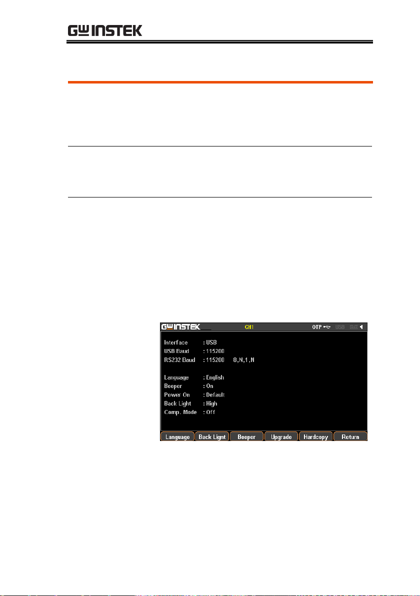
SYSTEM SETTINGS
Description
It can be used when upgrading the software
upgrades, screenshot operation and importing
or exporting files. Flash drive only support
USB2.0/USB3.0,FAT32 file system,16G MAX.
Operation
Insert flash driver into the USB Host port.
Then the system identifies the flash driver and
the indentification appears in the status bar.
Software Update
refer to page 92;
Screenshot
operation
In the target interface, press System button >
F1 (Setting) > F5 (Hardcopy) button and rotate
the scroll wheel (Encode) to locate the target
interface followed by pressing Enter key to
save screenshot. A confirm voice will sound
when successful.
The file format of screenshot is *.BMP and is saved
in the root directory of flash drive by default.
Description of Using Flash Drive
93
Page 94

GPP Series User Manual
Exporting the
Sequence data
The files of Sequence (*.SEQ), Recorder
(*.REC), Delay (*.DLY), etc within machine can
be, in addition to individual format, converted
to *.CSV file format for easy check and edit in
PC by user. For more details, refer to page 84.
94
Page 95

REMOTE CONTROL
REMOTE CONTROL
Connection Usage .................................................... 97
RS-232 ...................................................................... 98
USB .......................................................................... 99
GPIB ......................................................................... 101
LAN .......................................................................... 102
Command Syntax ................................................... 108
Command List ....................................................... 112
Measurement Instructions ...................................... 112
Display Functions .................................................... 112
Output Commands ................................................. 112
Source and Load Commands .................................. 113
Status Commands ................................................... 118
System Commands ................................................. 119
System Related Commands .................................... 120
IEEE488.2 Common Commands ............................ 120
Command Details .................................................. 121
Measurement Commands ...................................... 121
Display Commands ................................................. 123
Output Commands ................................................. 125
Source and Load Commands ............................... 129
Status Commands ................................................... 170
System Commands ................................................. 176
System Related Commands .................................... 185
SCPI Status Registers SCPI .................................... 186
95
Page 96

GPP Series User Manual
Event Registers ........................................................ 188
Enable Registers ...................................................... 188
Status Byte Register ................................................. 188
Standard Event Register .......................................... 190
Status Byte Register Commands............................. 191
Standard Event Register Commands ...................... 192
Other Status Register Commands .......................... 194
Errors ..................................................................... 195
Error Message .......................................................... 195
Command Errors ..................................................... 195
96
Page 97

REMOTE CONTROL
Port type
The GPP series has 2 standard remote control
ports (RS-232, USB), and 2 optional ports (GPIB,
LAN).
Port selection
It is allowed to control the GPP series by only
single remote control method once time. Before
to use, it’s required to select or confirm
beforehand.
Operation
Press the System button followed by pressing
the F1 (Interface) button to select the target
port: F1 (RS-232), F2 (USB), F3 (GPIB), F4
(LAN). The available ports will
appear on the LCD.
State
The selected port will appear in the status bar
with font color in gray, for instance , whilst
it will change to white color after successful
commnad operation.
Connection Usage
This chapter describes how to set and enable port,
as well as all the required preparations prior to
operation.
97
Page 98

GPP Series User Manual
Description
The GPP series models can be remotely
controlled by RS-232 connection.
Interface
Rear panel RS-232 port
Connection
Under power-off state, connect RS-232 cable
and select RS-232 port in the Interface. The
message USB232 will appear gray in the status
bar when connection, and turns to white color
while the first command connects succesfully.
Panel control will be automatically under lock
state when connection is successful.
Parameter
Setting
Press the System button followed by pressing
the F1 (Interface) button to select the target port:
F1 (RS-232). The setting of baud rate will appear
automatically, please then choose desired
setting.
Display
The parameter information of RS232 will appear
on LCD. Refer to the description below:
8 --->data bit 8bit
N --->no parity bit
1 --->stop bit 1bit
N --->no flow control bit
RS-232
98
Page 99

REMOTE CONTROL
Function check
Perform the following query:
*IDN?
The unit will return the manufacturer, model,
serial number and software version.
GW INSTEK, GPP-3323, SN: xxxxxxxx, Vx.xx
Disable Remote
Control Mode
Send a remote command Locall from the PC.
Long-press the F6 (unlock) key on the front
panel.
Warning: RS-232 is Not hot-plug device.
Please proceed to the connection procedure
under the power-off state.
Description
GPP can be connected via USB using the USB
Communications Device (CDC) class.
Interface
Rear panel USB slave port.
Installing the
Driver
Install the USB driver provided by suppiler in
PC.
USB
99
Page 100

GPP Series User Manual
Select USB port in the Interface after
connecting the USB cable. The message USB
will appear gray in the status bar when
connection, and turns to white color while the
first command connects succesfully.
The front panel keys are automatically locked
when the connection is successful.
Parameter Setting
Press the System button followed by pressing
the F1 (Interface) button to select the target
port: F2 (USB). The setting of baud rate will
appear automatically, please then choose
desired setting.
Display
The parameter information of USB will appear
on LCD. Refer to the description below:
115200----> transmission baud rate
Function Check
Perform the following query:
*IDN?
The unit will return the manufacturer, model,
serial number and software version.
GW INSTEK, GPP-2323, SN: xxxxxxxxx, Vx.xx
Disabling Remote
Control Mode
Send a remote command from the PC
Long-press the F6 (unlock) key on the front
panel.
Unplug the USB cable from the rear panel.
Note
USB devices are hot-plug devices. You can
directly remove the cable and exit.
100
 Loading...