

Page 1

Digital Power Meter
GPM-8310
USER MANUAL
Rev. A
ISO-9001 CERTIFIED MANUFACTURER
Page 2

This manual contains proprietary information, which is protected by
copyright. All rights are reserved. No part of this manual may be
photocopied, reproduced or translated to another language without
prior written consent of Good Will company.
The information in this manual was correct at the time of printing.
However, Good Will continues to improve products and reserves the
rights to change specification, equipment, and maintenance
procedures at any time without notice.
Good Will Instrument Co., Ltd.
No. 7-1, Jhongsing Rd., Tucheng Dist., New Taipei City 236, Taiwan.
Page 3

TABLE OF CONTENTS
Table of Contents
SAFETY INSTRUCTIONS .................................................. 5
GETTING STARTED ........................................................ 10
Characteristics .......................................... 11
Appearance ............................................... 16
Set Up ....................................................... 25
BASIC SETTING ............................................................. 28
Setting up measurement range ................. 29
Setting up measurement status ................ 33
Setting up System status .......................... 72
MEASUREMENT AND OTHER FUNCTIONS .................... 81
Measurement function .............................. 82
Other functions ........................................ 88
Integration measurement function ............ 91
Graph measurement function ................. 103
DIGITAL I/O / DA4 ....................................................... 121
Digital I/O / DA4 Overview ..................... 122
External Remote Control ......................... 124
DA4 Output Function .............................. 125
User / 4094 Mode ................................... 130
REMOTE CONTROL ...................................................... 136
Configure Remote Control Interface ........ 137
Configure EOL Character ........................ 144
Return to Local Control ........................... 144
COMMAND OVERVIEW ................................................ 145
Command Syntax .................................... 145
3
Page 4

GPM-8310 User Manual
Command List ........................................ 149
APPENDIX .................................................................... 228
Specifications ......................................... 229
Status system ......................................... 239
Dimensions ............................................ 243
Declaration of Conformity ....................... 244
Power measurement ............................... 245
Introduction to IEC-62301 ....................... 247
EUP Directive Lot6 specifications ........... 248
Connection Guide ................................... 249
4
Page 5
SAFETY INSTRUCTIONS
WARNING
Warning: Identifies conditions or practices that
could result in injury or loss of life.
CAUTION
Caution: Identifies conditions or practices that
could result in damage to the GPM-8310
or to other properties.
DANGER High Voltage
Attention Refer to the Manual
Protective Conductor Terminal
Earth (ground) Terminal
SAFETY INSTRUCTIONS
This chapter contains important safety
instructions that you must follow during
operation and storage. Read the following before
any operation to ensure your safety and to keep
the instrument in the best possible condition.
Safety Symbols
These safety symbols may appear in this manual or on the
instrument.
5
Page 6

GPM-8310 User Manual
Do not dispose electronic equipment as unsorted
municipal waste. Please use a separate collection
facility or contact the supplier from which this
instrument was purchased.
6
Page 7

SAFETY INSTRUCTIONS
General Guideline
CAUTION
Make sure that the voltage input level does not
exceed AC600V.
Make sure the current input level does not
exceed 20A.
Do not place any heavy object on the
instrument.
Avoid severe impact or rough handling that can
lead to damaging the instrument.
Do not discharge static electricity to the
instrument.
Use only mating connectors, not bare wires, for
the terminals.
Do not block or obstruct the cooling fan vent
opening.
Do not perform measurement at the source of a
low-voltage installation or at building
installations (Note below).
Do not disassemble the instrument unless you
are qualified as service personnel.
Make sure that the COM terminal to earth is
limited to 600Vpk.
Remove all test leads before disconnecting the
mains power cord from the socket.
If the equipment is used in a manner not
specified by the manufacturer, the protection
provided by the equipment may be impaired.
The device should be placed in a place where
the plug connected to it can be removed easily.
Safety Guidelines
7
Page 8

GPM-8310 User Manual
(Note) EN 61010-1:2010 specifies the measurement categories and
their requirements as follows. The GPM-8310 falls under category II
600V.
Measurement category IV is for measurement performed at the
source of low-voltage installation.
Measurement category III is for measurement performed in the
building installation.
Measurement category II is for measurement performed on the
circuits directly connected to the low voltage installation.
Power Supply
WARNING
AC Input voltage: 100-240 VAC 50/60Hz
The power supply voltage should not fluctuate
more than 10%.
Connect the protective grounding conductor of
the AC power cord to an earth ground, to avoid
electrical shock.
If grounding practice is not well implemented, a
certain amounts of noises will be generated
when connecting to GPM-001, the handy
measurement accessory for GPM-8310.
Cleaning the
Instrument
Disconnect the power cord before cleaning.
Use a soft cloth dampened in a solution of mild
detergent and water. Do not spray any liquid.
Do not use chemicals containing harsh material
such as benzene, toluene, xylene, and acetone.
Operation
Environment
Location: Indoor, no direct sunlight, dust free,
almost non-conductive pollution (Note below)
Temperature: 0°C to 40°C
Humidity: < 30°C: < 80%RH(non-condensing);
30°C~40°C:<70%RH(non-condensing);
>40°C: <50%RH (non-condensing)
Altitude: <2000m
Overvoltage category: OVC II
8
Page 9

SAFETY INSTRUCTIONS
(Note) EN 61010-1:2010 specifies the pollution degrees and their
requirements as follows. The GPM-8310 falls under degree 2.
Pollution refers to “addition of foreign matter, solid, liquid, or
gaseous (ionized gases), that may produce a reduction of
dielectric strength or surface resistivity”.
Pollution degree 1: No pollution or only dry, non-conductive
pollution occurs. The pollution has no influence.
Pollution degree 2: Normally only non-conductive pollution
occurs. Occasionally, however, a temporary conductivity caused
by condensation must be expected.
Pollution degree 3: Conductive pollution occurs, or dry, non-
conductive pollution occurs which becomes conductive due to
condensation which is expected. In such conditions, equipment
is normally protected against exposure to direct sunlight,
precipitation, and full wind pressure, but neither temperature
nor humidity is controlled.
Storage
environment
Location: Indoor
Temperature: -40°C to 70°C
Humidity: <90%RH(non-condensing)
Disposal
Do not dispose this instrument as unsorted
municipal waste. Please use a separate collection
facility or contact the supplier from which this
instrument was purchased. Please make sure
discarded electrical waste is properly recycled to
reduce environmental impact.
9
Page 10

GPM-8310 User Manual
Characteristics ................................................................ 11
Accessories .............................................................................................. 14
Package Contents .................................................................................... 15
Appearance ..................................................................... 16
Front Panel .............................................................................................. 16
Main Display Overview ........................................................................... 19
Rear Panel ................................................................................................ 22
Set Up ............................................................................ 25
Tilting the Stand ...................................................................................... 25
Power Up ................................................................................................. 26
Connect the wires to the GPM-8310 ....................................................... 27
GETTING STARTED
This chapter describes the GPM-8310 in a nutshell,
including accessories, package contents, its main
features and front / rear panel introduction.
10
Page 11
GETTING STARTED
Operation
Press the buttons on the front panel to easily
turn on the GPM-8310 measurement function.
All settings and measurements results are
displayed on the 5-inches TFT-LCD screen panel
for easy use of each function.
Standard display mode: 2 main measurement
results and 8 secondary measurement results are
displayed in this screen.
Simple display mode: 4 major measurement
results are displayed in this screen.
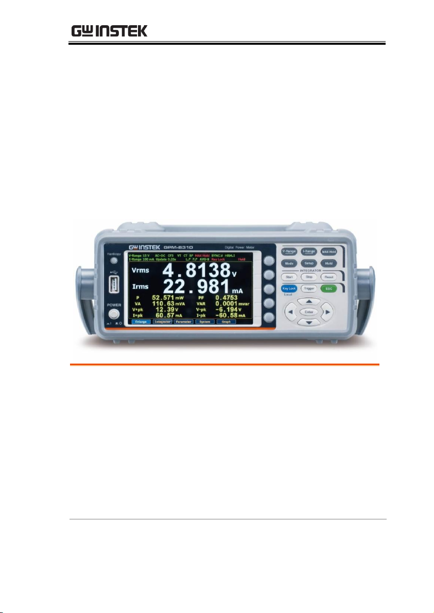
Characteristics
The GPM-8310 is a high-precision, programmable power meter for
using in standby measuring the device with low power such as
switching power supplies, transformers, power supplies, adapter
and other devices. It equips with a color TFT-LCD screen and also
multiple graph displays which are very convenient for reading the
measurement results. The GPM-8310 has become a reliable power
measurement instruments because of its simple operation, excellent
performance, user-friendly graph displays and automatic
measurement interface.
11
Page 12

GPM-8310 User Manual
Performance
6 selectable voltage ranges available from 15V to
600V with 0.1% of reading + 0.05% of range.
12 selectable current ranges available from 5mA
to 20A with 0.1% of reading + 0.05% of range.
It can even measure the voltage of abnormal
wave of CF 3. The half-range CF is up to 6 or 6A.
It can even measure the current of abnormal
wave of CF 3. The half-range CF is up to 6 or 6A.
Total harmonic distortion measurement.
50-orders harmonic test and analysis function.
Graph display for measurement results
including harmonic orders distribution.
Plug-in USB disk data store function including
log and screenshot.
Auto range function for integration measurement.
12
Page 13

GETTING STARTED
Features
Full five-digit measurement.
Voltage measurement range: 15V ~ 600V or
automatic switching
Current measurement range: 5mA ~ 20A or
automatic switching
Maximum accuracy of 0.1% of reading + 0.05%
of range
2 main measurement readings and 8 minor
measurement readings are displayed in the
screen of standard display mode.
4 main measurement readings are displayed in
the screen of simple display mode.
Added stand-alone display of total harmonic
distortion measurement function (50 steps)
Test bandwidth of voltage and current: DC ~
100kHz.
Selectable boot settings (Previous / Default)
Waveform display up to 10kHz along with
Harmonic bar and list table
Interface
Standard interface: USB / RS232 / LAN / GPIB
Optional interface: Digital IO / DA4
Application
It can be applied to production test such as
power supplies, transformers, motors, electrical
equipment and other equipment with low standby
power.
It can be applied to power measurement
conforms to IEC 62301
It can be applied to assess the power
consumption of product design.
13
Page 14

Accessories
Standard Accessories
Part number
Description
82PM-83100E01
User Manual CD
82GW1SAFE0M01
Safety Instruction Sheet
Region dependent
Power Cord
GTL-209
Test leads: 1x red, 1x black
GTL-212
Test leads: 1x yellow, 1x blue
Optional Accessories
Part number
Description
GPM-001
Test Fixture
GTL-234
RS232C cable
GTL-246
USB cable
GTL-248
GPIB cable
GCP-300
Current Probe
GRA-422
Rack Adapter Panel (19”, 2U)
Option
Name
Description
Opt.01
DA4 (Factory installed)
GPM-8310 User Manual
14
Page 15
GETTING STARTED
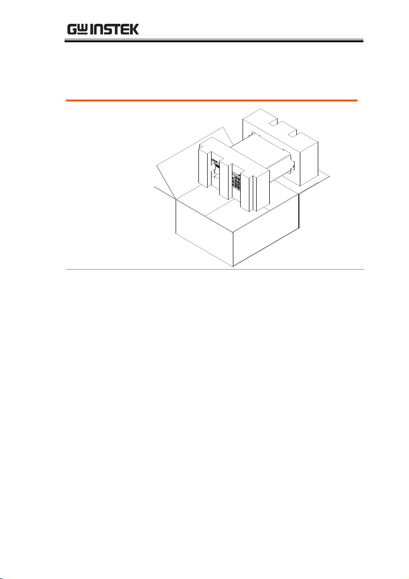
Opening the box
Contents
(single unit)
Main unit
Test leads (red x1,
black x1, yellow x1,
blue x1)
Power cord x1 (region
dependent)
User manual CD
Safety instruction
sheet
Package Contents
Check the contents before using the instrument.
15
Page 16
Appearance
Digital Power Meter
POWER
V-Range
MAX Hold
Mode
Setup
Hold
I-Range
Start
Stop
Reset
Local
Trigger
ESC
INTEGRATOR
Enter
Key Lock
Hardcopy
GPM -8310
: Long Push
LCD Display Function Keys
Enter
Key
Soft
keys
Arrow
Keys
Trigger
Key
ESC
Key
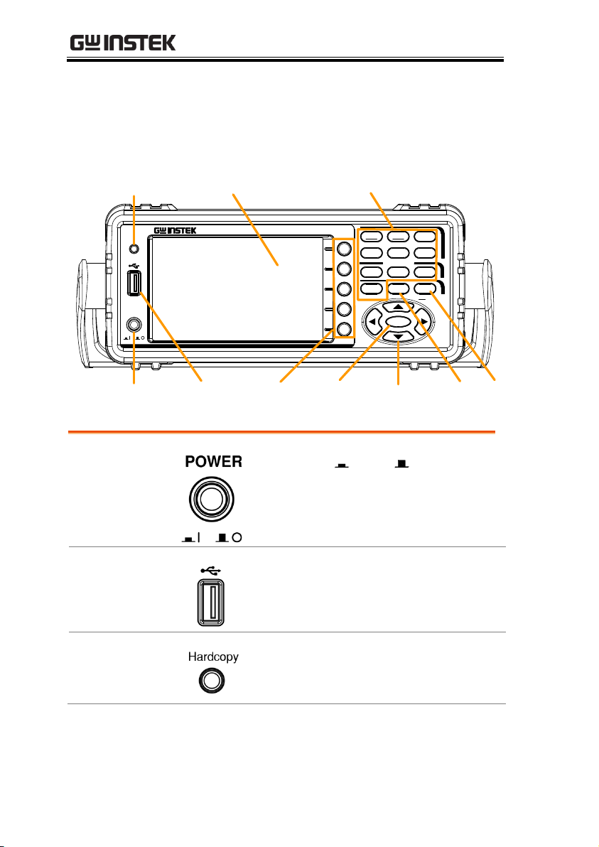
Power
key
USB Host
Port
Hardcopy Key
Power Key
Turns On or Off the main
power. For the power up sequence,
see page 26.
USB Host Port
Connects with USB flash drive for
data storage or screenshot.
Hardcopy Key
Captures the current screenshot or
saves the data log for reading. For
details, refer to page 67.
Front Panel
GPM-8310 User Manual
16
Page 17
GETTING STARTED
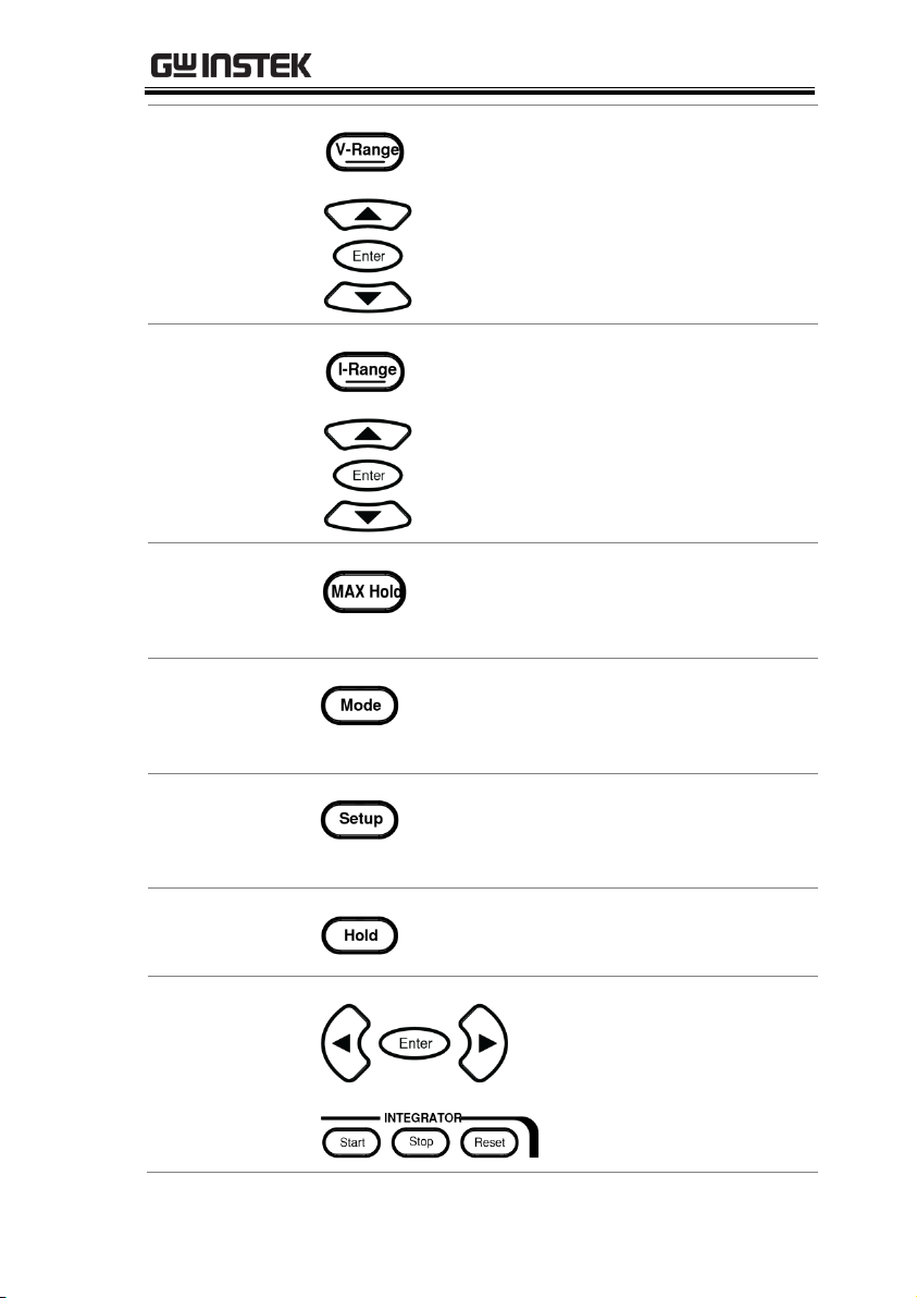
Function Keys
V-Range key, up/down arrow keys
and Enter key can be used together
to select a voltage range or auto
range measurement mode. Also,
press and hold the V-Range key to
toggle between manual and auto
range setting. See page 29.
I-Range key, up/down arrow keys
and Enter key can be used together
to select a current range or auto
range measurement mode. Also,
press and hold the I-Range key to
toggle between manual and auto
range setting. See page 29.
Press this button to display the
maximum measurement reading.
See page 89.
Press this key to select measure
mode (DC/AC/AC+DC/V-MEAN).
See page 90.
Press this key to enter the
measurement settings menu. See
page 33.
Press this key to switch window and
stop refreshing. See page 89.
Use the left and right
arrow keys to select
Integrator mode, and
press Enter button to
enter the time integrator
function. See page 91.
17
Page 18
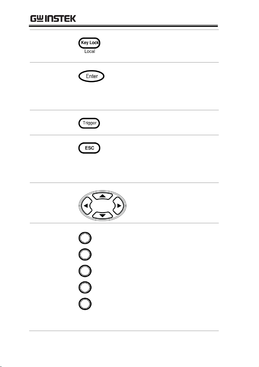
GPM-8310 User Manual
Press this key to toggle to key lock. In
Remote control mode, press this button
to switch to local mode. See page 90.
Enter Key
This button is used to enter the menu,
confirm the settings and switch
between the standard display mode
and simple display mode (no function
table and display icon). See page 89.
Trigger key
Activates the Trigger function. See
page 89.
ESC Key
Press this button to cancel the
current setting. The cursor returns to
the default position or return to the
previous menu according to the
situation. See page 90.
Arrow Keys
This four arrow keys are
used to edit the parameters,
browse the menu system and
select the parameter range.
Soft Keys
The 5 soft keys have varied functions
from the OSD (On-Screen Display)
options, individually, per different
settings. In addition, from the main
display, the 5 soft keys act like
shortcuts leading to the 5 secondary
menus, for which refer to the page 21.
The mapping sequence is from top to
bottom of soft keys corresponding to
from left to right of secondary menus.
For instance, the top soft key enables
shortcut to the far left secondary
menu (Enlarge) directly.
18
Page 19
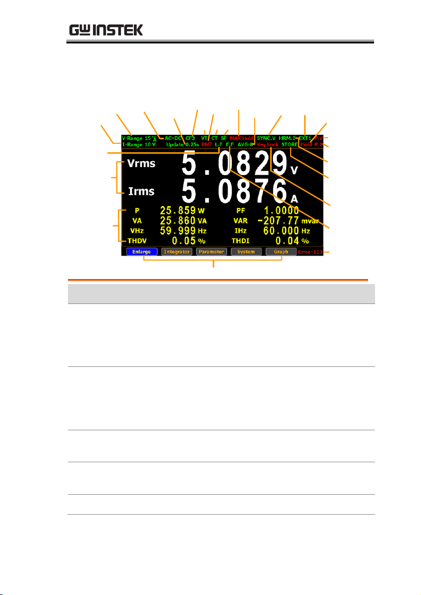
GETTING STARTED
Current Range
Voltage Range
Mode
Update Rate
CF
VT
Remote
CT SF
Max. Hold
Average
Key Lock
Sync
Source
External
Display Hold
Peak Voltage
Peak Current
Harmonic
Calculation
Measure
Storage
Frequency
Filter
Remote Error
Secondary Menus
Minor
Measurement
Display
Line Filter
Main
Measurement
Display
Item
Status icon
Description
Voltage Range
V-Range 15V
Voltage measurement range.
Example here range is 15V.
V-Auto means that Voltage Auto
Range is turned on.
Current Range
I-Range 5A
Current measurement range.
Example here range is 5A.
I-Auto means that Current Auto
Range is turned on.
Mode
AC+DC
Measurement mode
(AC, DC, AC+DC, V-MEAN)
Date Update
Rate
Update 0.1s
Data update rate
(0.1/0.25/0.5/1/2/5/10/20/Auto)
Crest Factor
CF3
Crest Factor (3/6/6A)
Main Display Overview
19
Page 20

GPM-8310 User Manual
VT Ratio State
VT
External voltage magnification
(On/Off)
CT Ratio State
CT
External current magnification
(On/Off)
Power Ratio
State
SF
External power magnification
(On/Off)
Remote
RMT
Remote control mode (On/Off)
Line Filter
L.F
Voltage and current filters (On/Off)
Frequency Filter
F.F
Frequency filters (On/Off)
Maximum Hold
MAX Hold
Retain and display the maximum
measurement reading.
Average
AVG-8
Average number of sampling
(8/16/32/64)
Sync Source
SYNC.V
Synchronization source (V/I/Off)
Keyboard Lock
Key Lock
Lock Key button
Harmonic
Calculation
HRM.I
Harmonic calculation method
(IEC/CSA/Off)
Measure Storage
STORE
Measured date storage (On/Off)
External Input
EXT1
External signal input function
(Ext1/Ext2/Off)
Display Hold
Hold
Retain and display the current
measurement reading.
Peak Voltage
P.V
The voltage exceeds the
measurement range
Peak Current
P.I
The current exceeds the
measurement range
Remote Error
Error-XXX
An error occurs in remote
command
20
Page 21

GETTING STARTED
Standard Display
Mode
Display the measurement result of 2 major and 8
minor measurement parameters
Simple Display
Mode
Display the measurement result of 4 major
measurement parameters
Secondary menus
Display secondary function menu
Enlarge
This function key is used to
switch display of measurement
result from 2 major plus 8 minor
to 4 major ones.
Integrator
This function key is used to set up
integrator measurement
parameters and execute integrator
measurement function.
Parameter
This function key is used set up
measurement parameters.
System
This function key is used to enter
the system setting and system
configuration screens.
Graph
This function key is used to set up
graph measurement settings and
execute measurement in the
intuitive graph displays.
21
Page 22
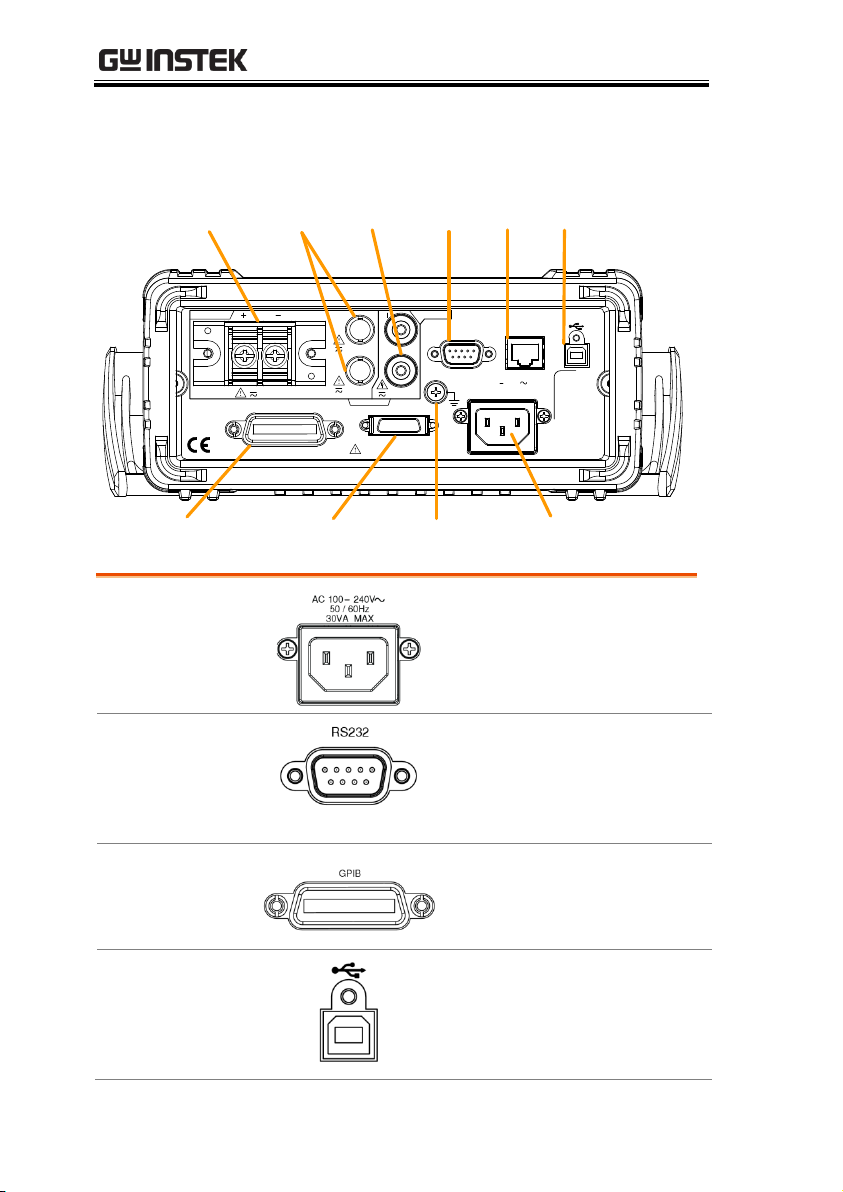
Rear Panel
I I
20A MAX
100 240V
30VA MAX
AC
50 / 60Hz
CAT II 600V
REMOVE INPUTS
TO AVOID SHOCK,
WARNING
CURRENT
V
VOLTAGE
V
600VMAX
EXT1
EXT2
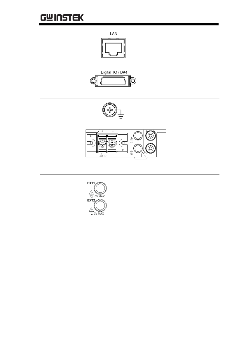
LAN
RS232
GPIB
Digital IO / DA4
SER.NO. LABEL
BEFORE OPENING.
10V MAX
2V MAX
Current
Input
GPIB
Connector
External
Input 1/2
Voltage
Input
Digital IO / DA4
Connector
RS-232
Connector
LAN
Port
USB Device
Port
GND
Terminal
Power Cord
Socket
Power Cord
Socket
Connects the power cord.
AC 100~240V ±10%,
50/60Hz
RS232 Connector
Accepts an RS-232C cable for
remote control; DB-9 male
connector. For remote
control details, see page 138.
GPIB Connector
Accepts an optional GPIB
card for remote control. For
GPIB details, see page 140.
USB Device Port
Accepts a USB device cable
for remote control; Type B,
female connector. For remote
control details, see page 137.
GPM-8310 User Manual
22
Page 23
GETTING STARTED
LAN Port
Accepts a LAN for remote
control. For remote control
details, see page 142.
Digital IO / DA4
Connector
Accepts a digital I/O cable
for signal output; SCSI 26 pin,
female connector. For digital
I/O details, see page 122
GND Terminal
Connects the GND (ground)
terminal to the earth ground.
Voltage/Current
input terminal
I I
20A MAX
CAT II 600V
CURRENT
V
VOLTAGE
V
600VMAX
EXT1
EXT2
10V MAX
2V MAX
Voltage/Current
input terminals is
used to connect
the main
measurement
signals.
External Input 1/2
Connects output signal to the EXT1
terminal which receives up to 10V, or
the EXT2 terminal that receives at the
maximum of 2V. See page 59 for setting.
23
Page 24

GPM-8310 User Manual
Warning
Do not use damaged device. Before using the
equipment, check its housing first to sure there is
no any cracks. Do not operate this device in an
environment containing explosive gases, steam or
dust.
The maximum measurable current and voltage are
600 V and 20A for voltage and current terminals of
the rear panel of the GPM-8310. Do not input
exceeded voltage and current, otherwise it will burn
the device.
The maximum input voltage are 10 V and 2V for
EXT1 and EX2 terminals of the rear panel of the
GPM-8310. Do not input exceeded voltage,
otherwise it will burn the device.
Always use the supplied cable for connection.
Before connecting the device, observe all the safety
symbols marked on the device.
Turn off the power to the device and the application
system before connecting I/O terminals.
Do not install replacement parts on the device or
perform any unauthorized modifications.
Do not use this device if the removable cover is
removed or loosened.
Do not connect any cables and terminals before
performing self-test.
Use only the power adapter supplied by the
manufacturer to avoid accidental injury.
Do not use this device for life support systems or
any other equipment that has safety requirements.
24
Page 25
GETTING STARTED
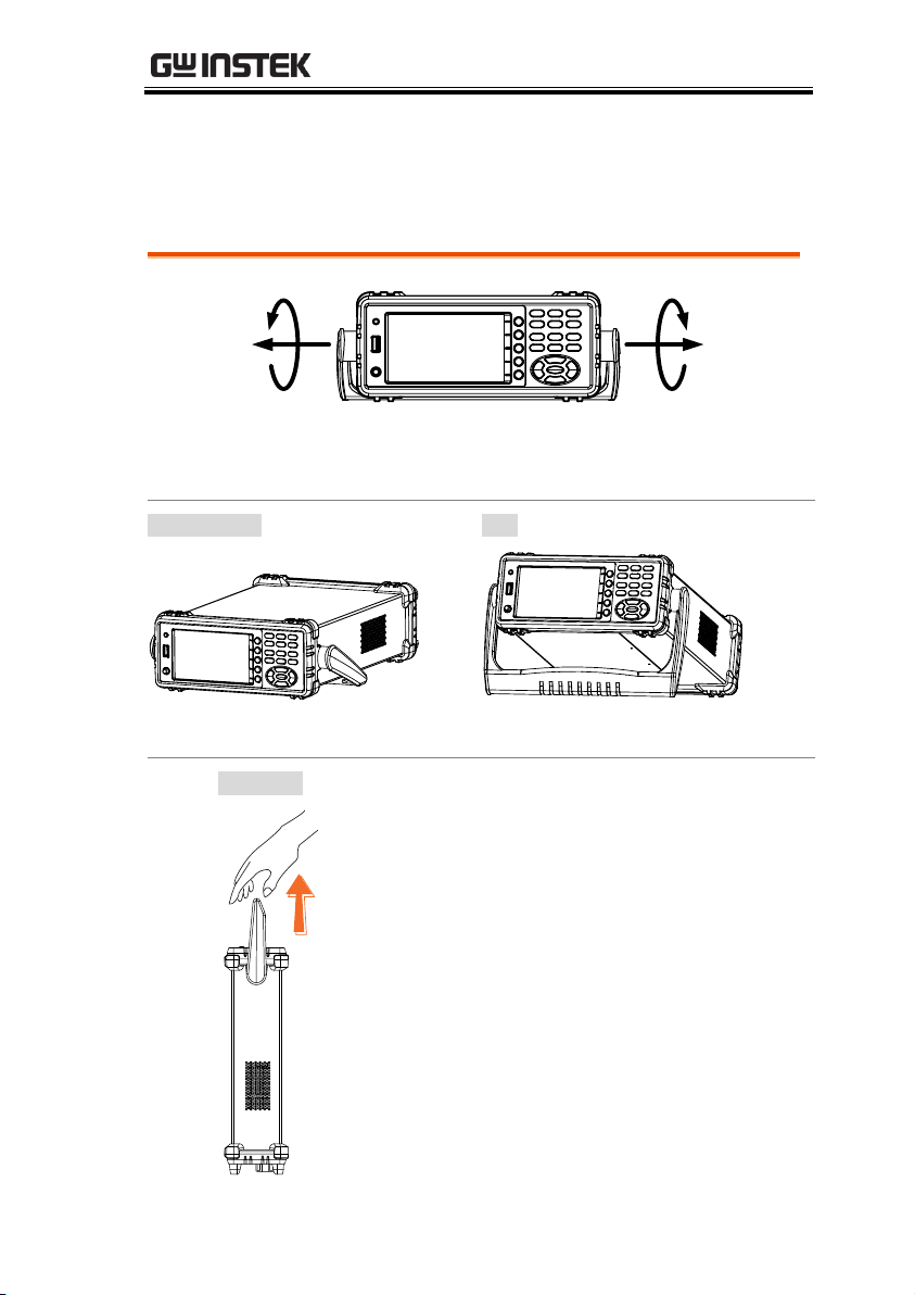
Pull out the handle sideways and rotate it clockwise for the several
applications listed below.
Horizontal
Tilt
Place the unit horizontally.
Rotate the handle for tilt stand.
Vertical
Place the handle vertically for hand carry.
Set Up
Tilting the Stand
25
Page 26
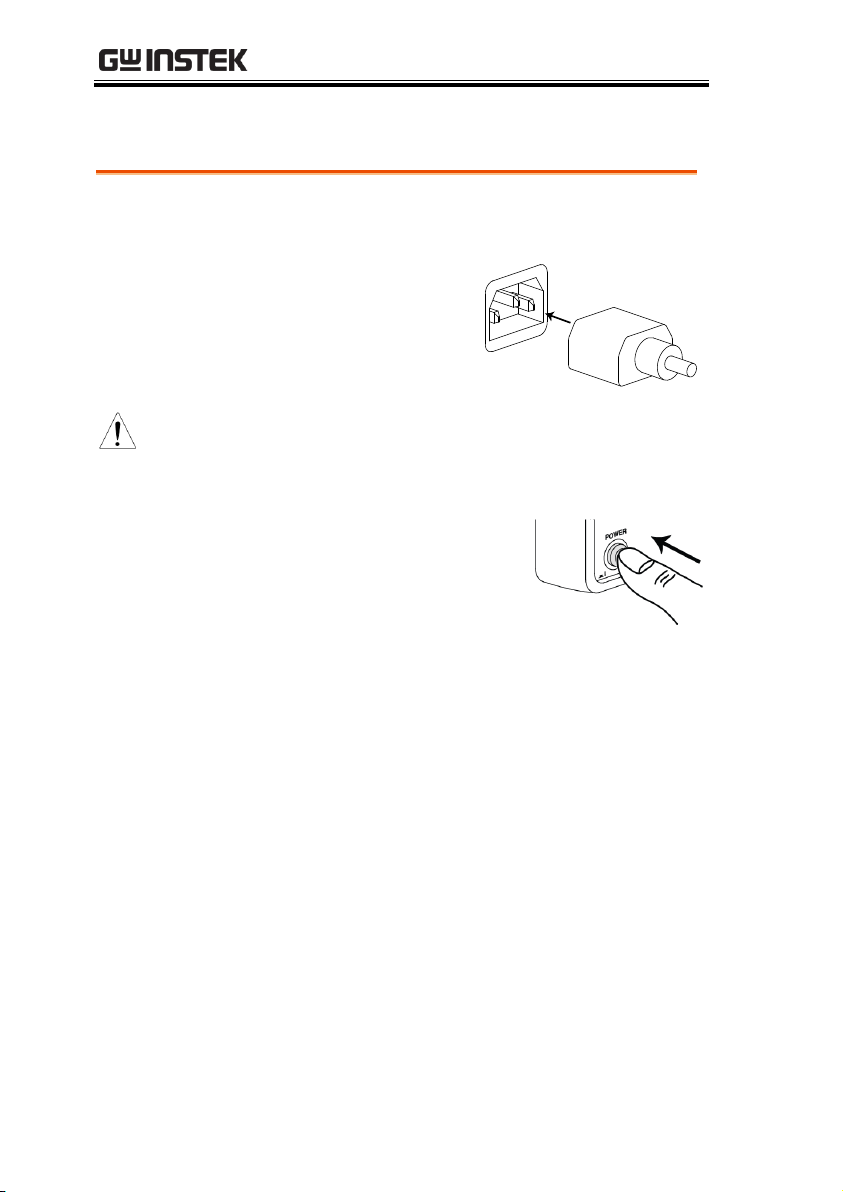
Power Up
Steps
1. Ensure the AC voltage is 100~ 240V.
2. Connect the power
cord to the AC
voltage input.
Note
Make sure the ground connector on the power
cord is connected to a safety ground. This will
influence the measurement accuracy.
3. Push to turn on the main
power switch on the front
panel.
4. The display turns on and shows the last
function that was used before the power was
reset.
GPM-8310 User Manual
26
Page 27
GETTING STARTED
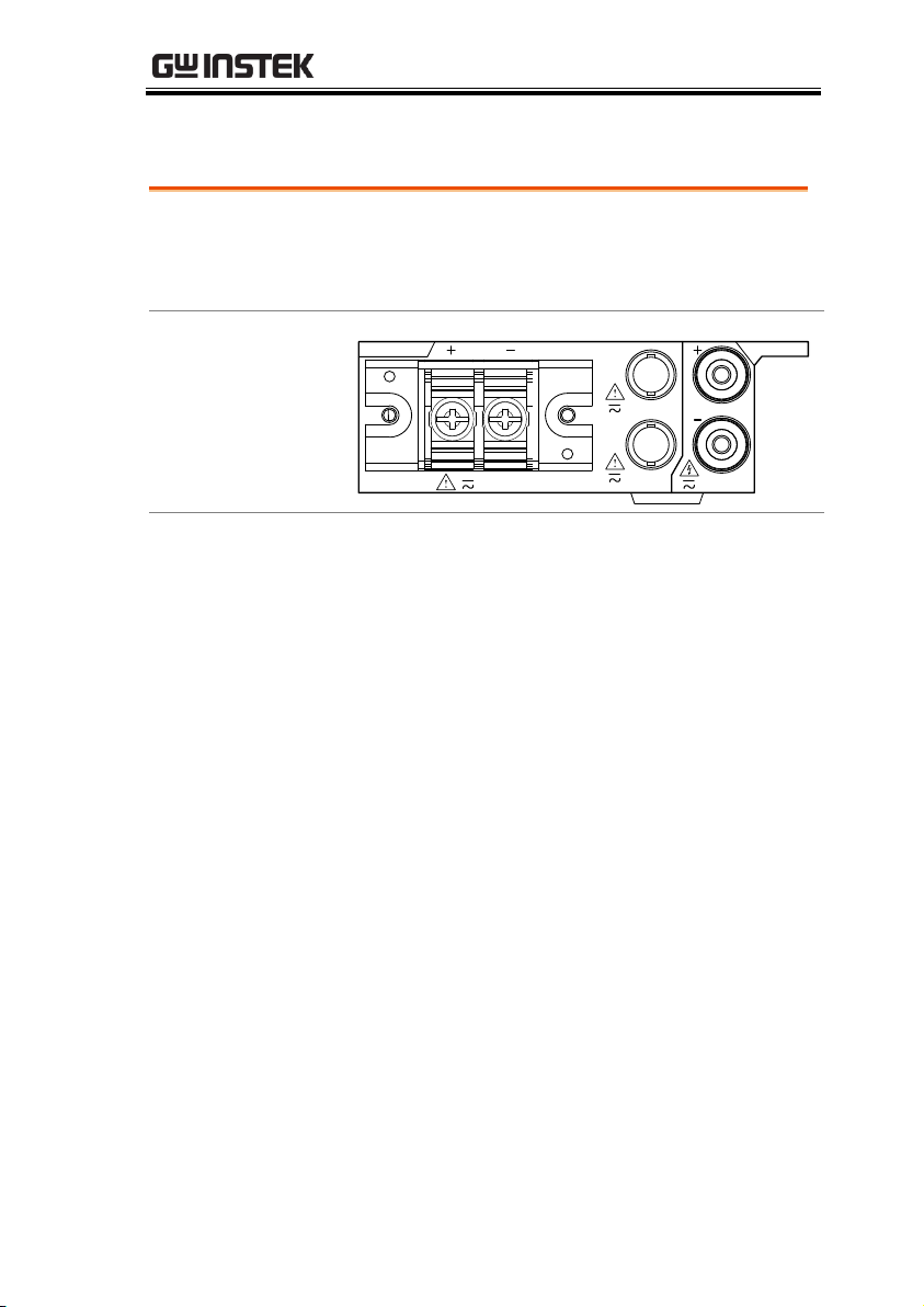
Background
Two separate wires is used to connect the
GPM-8310, so voltage and current
measurement are isolated and don’t interfere
with each other.
Connection
diagram
I I
20A MAX
CAT II 600V
CURRENT
V
VOLTAGE
V
600VMAX
EXT1
EXT2
10V MAX
2V MAX
Description
V +
The positive voltage input (+), 600V for
input on the rear panel.
V -
The negative voltage input (-), 600V for
input on the rear panel.
I +
The positive current input (+), 20A for
input on the rear panel.
I -
The negative current input (-), 20A for
input on the rear panel.
EXT1
The external 1 voltage input, 10V for input
on the rear panel.
EXT2
The external 2 voltage input, 2V for input
on the rear panel.
Connect the wires to the GPM-8310
27
Page 28

GPM-8310 User Manual
Setting up measurement range ........................................ 29
Auto Range .............................................................................................. 31
Setting up measurement status ....................................... 33
Setting up synchronization source ......................................................... 33
Setting up line filter ................................................................................. 34
Setting up frequency filter ....................................................................... 35
Setting up crest factor ............................................................................. 36
Setting up auto-zero function ................................................................. 37
Setting up method of calculating harmonics ......................................... 38
Setting up data update rate ..................................................................... 40
Setting up measure storage .................................................................... 42
Setting up average function .................................................................... 44
Setting up the voltage and current skipping configuration ................... 46
Setting up the skipping configuration for external ................................. 50
Setting up the VT ratio state ................................................................... 53
Setting up the CT ratio state ................................................................... 55
Setting up the power ratio state .............................................................. 57
Setting up the external sensor input terminal ........................................ 59
Saving and loading the setup parameters .............................................. 61
Setting up the D/A output configuration ............................................... 63
Setting up the hardcopy and log configuration ...................................... 67
Setting up the MATH configuration ....................................................... 69
Setting up System status ................................................. 72
System information screen ..................................................................... 72
System configuration screen ................................................................... 73
Setting up power on status ..................................................................... 75
Setting up brightness .............................................................................. 76
Setting up key sound ............................................................................... 77
Setting up remote interface ..................................................................... 78
Setting up SCPI identity .......................................................................... 80
BASIC SETTING
28
Page 29
BASIC SETTING
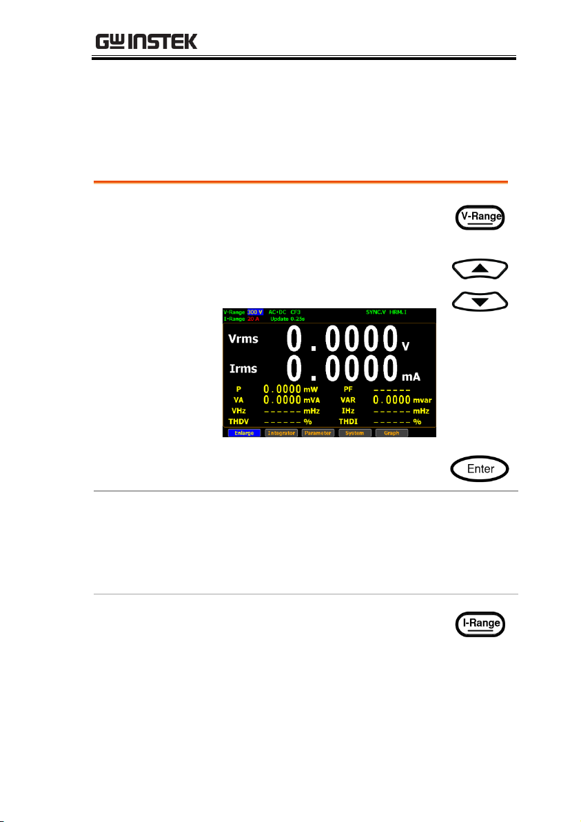
Set voltage range
1. Press V-Range button. The V-
Range field turns to bluish.
2. Use up and down arrow keys to
select the desired range.
3. Press Enter button to confirm your
selection.
Available range
Crest Factor
is 3:
AUTO, 15V, 30V, 60V, 150V, 300V, 600V
Crest Factor
is 6/6A:
AUTO, 7.5V, 15V, 30V, 75V, 150V, 300V
Set current range
1. Press I-Range button. The I-Range
field turns to bluish.
Setting up measurement range
To get the accurate measurement results, you should set an
appropriate measurement range before you perform measurement
task.
29
Page 30
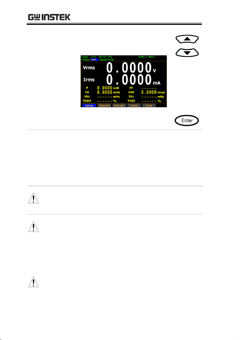
GPM-8310 User Manual
2. Use up and down arrow keys to
select the desired range.
3. Press Enter button to confirm your
selection.
Available range
Crest Factor
is 3:
AUTO, 5mA, 10mA, 20mA, 50mA,
100mA, 200mA, 0.5A, 1A, 2A, 5A, 10A,
20A
Crest Factor
is 6/6A:
AUTO, 2.5mA, 5mA, 10mA, 25mA,
50mA, 100mA, 250mA, 0.5A, 1A, 2.5A,
5A, 10A
Note
When it is under the manual setting ranging from
5mA to 200mA, the manual range adjusts to auto
range automatically if input current exceeds 700mA.
Note
When the measurement range is set manually, if the
range status icon lights in green means that the
measured value meets the setting range. On the
contrary, If the range status icon lights in red means
that the measured value doesn’t meet the best setting
range. In this case. It is better to switch to other range
to get more accurate measurement results.
Note
The P.I status icon lights in red when the current
measurement circuit detects that the measured value
exceeds setting range by 3 folds (CF is set to 3) or 6
folds (CF is set to 6/6A).
30
Page 31

BASIC SETTING
Note
The P. V status icon lights in red when the voltage
measurement circuit detects that the measured value
exceeds setting range by 3 folds (CF is set to 3) or 6
folds (CF is set to 6/6A).
Range is shift up
The range is shifted up when either of the
following conditions is met.
Vrms or Irms exceeds the measurement range
by 130% at CF 3/6.
Vrms or Irms exceeds the measurement range
by 260% at CF 6A.
The Vpk or Ipk value of the input signal exceeds
the current setting range by 300% at CF 3.
The Vpk or Ipk value of the input signal exceeds
the current setting range by 600% at CF 6/6A.
Range is shift
down
The range is shifted down when all of the
following conditions are met.
Vrms or Irms is equal to or less than the
measurement range by 30% at CF 3/6/6A.
Vrms or Irms is equal to or less than the next
lower measurement range by 125% at CF
3/6/6A.
The Vpk or Ipk value of the input signal is equal
to or less than the next lower measurement
range by 300% at CF 3.
The Vpk or Ipk value of the input signal is equal
to or less than the next lower measurement
range by 600% at CF 6/6A.
Auto Range
The range is automatically switched according to the voltage and
current of input signal.
31
Page 32

GPM-8310 User Manual
Example
To begin with, the measured Irms value is
within the current range of I-Auto 20mA.
The measured Irms (27.194mA) exceeds the IAuto 20mA by 130%, so the range is shifted up
to 50mA automatically.
The measured Irms (3.9994mA) is less than 30%
of the I-Auto 20mA, so the range is shifted
down to 10mA automatically.
32
Page 33

BASIC SETTING
Steps
1. Press Setup button.
2. Press Enter button.
3. Press down arrow key to move
cursor to the Sync Source field.
4. Use soft keys to select and confirm
the desired option.
Option
V
Select the voltage of signals as
synchronization source. The SYNC.V status
icon, for example, on the display lights up in
green when V is selected for sync source.
I Select the current of signals as
synchronization source.
Off
Select the entire interval of data updating
period as synchronization source.
Default value
V
Setting up measurement status
Setting up synchronization source
33
Page 34

GPM-8310 User Manual
Steps
1. Press Setup button.
2. Press Enter button.
3. Press down arrow key to move
cursor to the Line Filter field.
4. Use soft keys to select and confirm
the desired option.
Option
On
Turn on the line filter function, which is
inserted into voltage and current
measurement input circuits and affects
voltage, current as well as power
measurements without high frequency
components included within measured
values. The L.F status icon on the display
lights up in green.
Off
Turn off the line filter function. The cutoff
frequency is 500Hz.
Default value
Off
Setting up line filter
34
Page 35

BASIC SETTING
Steps
1. Press Setup button.
2. Press Enter button.
3. Press down arrow key to move
cursor to the Frequency Filter field.
4. Use soft keys to select and confirm
the desired option.
Option
On
Turn on the frequency filter function, which
is inserted into frequency measurement
input circuit and affects frequency
measurements with high frequency
components included within measured
values. The F.F status icon on the display
lights up in green.
Off
Turn off the frequency filter function. The
cutoff frequency is 500Hz.
Default value
Off
Setting up frequency filter
35
Page 36

GPM-8310 User Manual
Steps
1. Press Setup button.
2. Press Enter button.
3. Press down arrow key to move
cursor to the Crest Factor field.
4. Use soft keys to select and confirm
the desired option.
Option
3
Crest Factor is 3.
6 Crest Factor is 6.
6A
Crest Factor is 6A where input range of
measurement range will be extended and
greater than 6. This is practical for
restraining from frequent range changes
while measuring, under auto range, a
distorted waveform.
Default value
3
Setting up crest factor
36
Page 37

BASIC SETTING
Steps
1. Press Setup button.
2. Press Enter button.
3. Press down arrow key to move
cursor to the Auto Zero field.
4. Use soft keys to select and confirm
the desired option.
Option
On
Auto-zero function is activated once per
hour or when range is switched.
Off
Auto-zero function is only activated once
when the range is switched. The auto-zero
function is turned off when the integrator
function is executed.
Default value
Off
Setting up auto-zero function
37
Page 38

GPM-8310 User Manual
Steps
1. Press Setup button.
2. Press Enter button.
3. Press down arrow key to move
cursor to the Harmonics field.
4. Use soft keys to select and confirm
the desired option.
Option
IEC
Calculate the ratio of harmonic quantity of
the 2nd through the upper limit 50th
harmonic to the 1st harmonic. The HRM.I
status icon, for example, on the display
lights up in green when IEC is selected for
harmonics.
CSA
Calculate the ratio of harmonic quantity of the
2nd through the upper limit 50th harmonic to
the 1st through the 50th harmonic.
Off
Turn off the harmonic calculation function.
Default value
IEC
Steps
5. Press right arrow key to move
cursor to Order field.
Setting up method of calculating harmonics
38
Page 39

BASIC SETTING
6. Use soft keys to increase or
decrease the order number.
Option
1-50
Set the upper limit of measured harmonic
order within the range from 1 to 50.
Default value
50
39
Page 40

GPM-8310 User Manual
Steps
1. Press Setup button.
2. Press Enter button.
3. Press down arrow key to move
cursor to the Data Update Rate field.
4. Use soft keys to select and confirm
the desired option. Press the
“More” soft keys to toggle among
pages for further options.
Option
0.1s/0.25s/
0.5s/1s/2s/
5s/10s/20s
Measured value is updated in
accordance with the designated time
interval. The Update 5s status icon, for
example, on the display lights up in
green when 5s option is selected.
Auto
Data is only updated when a set
period (Time Out) of the input
waveform is detected.
Default value
0.25s
Steps
5. When Auto is selected, press right
arrow key to move cursor to Time
Out field.
Setting up data update rate
40
Page 41

BASIC SETTING
6. Use soft keys to select and confirm
the desired option.
Option
1s/5s/
10s/20s
Time Out period acts like the time limit
for detecting a period of the input
waveform.
Default value
1s
Note
Time Out function is only available when Auto is
selected for Data Update Rate.
41
Page 42

Steps
1. Press Setup button.
2. Press Enter button.
3. Press down arrow key to move
cursor to the Measure Storage field.
Note
Measure Storage function is Not
available when Auto is selected
for Data Update Rate.
4. Use soft keys to select and confirm
the desired option.
Option
On
All measured date will be stored to the
internal memory by designated time interval
for repeating the storage operation. The
STORE status icon, for example, on the
display lights up in green when Measure
Storage function is turn on.
Off
Turn off the measure storage function.
Default value
Off
Steps
5. Press down arrow key to move
cursor to Interval field.
GPM-8310 User Manual
Setting up measure storage
42
Page 43

BASIC SETTING
6. Use soft keys to increase or
decrease the interval.
Option
The setting range for Interval is from 00:00:00 to
99:59:59.
Default value
00:00:00
Note
When it is set 00:00:00, the interval for measure
storage will be synchronized with the designated
Data Update Rate.
Storage stops in the following circumstances:
When data has been stored to all blocks,
Normal measure data can be stored 10000
blocks and Normal with Harmonic data can be
stored 1000 blocks.
When the storage setting is set to Off (while
storage is in progress)
If you press the HOLD key to hold the display
while storage is in progress, the measurement
operation and the storage interval time counter
are held (paused), which causes the storage
operation itself to be held. If integration is in
progress, this instrument continues
measurement and integration in the
background.
43
Page 44

GPM-8310 User Manual
Steps
1. Press Setup button.
2. Press Average soft key.
3. Press Enter button.
4. Press down arrow key to move cursor
to the State field.
5. Use soft keys to select and confirm the
desired option.
Option
On
Turn Average function On for either Linear
or Exponential averages of numeric data. It
is particularly practical for large changes in
load or power of low input signal frequency.
Off
Turn off Average function.
Default value
Off
Steps
6. Press down arrow key to move cursor
to Type field.
Setting up average function
44
Page 45

BASIC SETTING
7. Use soft keys to select and confirm the
desired option.
Option
Linear
With the designated linear count, it is
used to compute linear averages.
Exponent
With the specified attenuation count,
numeric data will be averaged
exponentially.
Default value
Linear
Steps
8. Press down arrow key to move cursor
to Count field.
9. Use soft keys to select and confirm the
desired option.
Option
8/16/
32/64
It includes 8, 16, 32 and 64 for
exponentially attenuation count and
linearly average count. The AVG-8 status
icon, for example, on the display lights up
in green when 8 is selected for average.
Default value
8
45
Page 46

GPM-8310 User Manual
Steps
1. Press Setup button.
2. Press V / I Range soft key.
3. Press Enter button.
4. Press down arrow key to move
cursor to the Mode field.
5. Use soft keys to select and confirm
the desired option.
Option
Menu
When user is configuring range setting, the
measured data will Not be displayed.
Quick
The measured data will be displayed
simultaneously while measurement range
is being switched by user. This is practical
for frequent switch of measurement range.
Default option
Menu
Steps
6. Press down arrow key to move
cursor to Skipping Config field.
Setting up the voltage and current skipping configuration
46
Page 47

BASIC SETTING
7. Use soft keys to select and confirm
the desired option.
Option
On
It is able is skip certain measurement
range(s) that are not used by turning on
this feature. It can reduce measured data
loss which happens while ranges are
switched.
Off
Turn off the function.
Default option
Off
Steps
8. Press down arrow key to move
cursor to each field of both
V-Range and I-Range.
9. Use soft keys to enable or disable the
skipping function for each range.
Option
On
The box of range will be checked when the
range is enabled for skipping function.
Off
The range is disabled for skipping function.
47
Page 48

GPM-8310 User Manual
Default option
Off
Steps
10. Press down arrow key to move
cursor to Peak Over field for VRange and I-Range, respectively.
11. Use soft keys to select and confirm
the desired option. Press the More
soft key to toggle among pages for
Peak Over of V-Range and I-Range.
Option
When the occurrence of peak over-range happens
in Auto range mode, user is able to define a
measurement range to switch to. The available
options for each mode are listed below.
When it is under CF3 mode for V-Range.
Off/15V/30V /60V/150V/300V/600V
When it is under CF6/6A mode for V-Range.
Off/7.5V/15V /30V/75V/150V/300V
When it is under CF3 mode for I-Range.
Off/5mA/10mA/20mA/50mA/100mA/200mA/0.5A
/1A/2A/5A/10A/20A
When it is under CF6/6A mode for I-Range.
Off/2.5mA/5mA/10mA/25mA/50mA/100mA/250
mA/0.5A/1A/2A/5A/10A
Default option
Off
48
Page 49

BASIC SETTING
Note
The available options for Peak Over field are
limited within the selected options from the VRange and I-Range sections above.
49
Page 50

GPM-8310 User Manual
Steps
1. Press Setup button.
2. Press V / I Range soft key.
3. Press Enter button.
4. Press down arrow key to move
cursor to Skipping Config field.
5. Use soft keys to select and confirm
the desired option.
Option
On
It is able is skip certain measurement
range(s) that are not used by turning on
this feature for external input. It can reduce
measured data loss which occurs while
ranges are switched.
Off
Turn off the function.
Default option
Off
Steps
6. Press ESC button.
7. Press External soft key.
Setting up the skipping configuration for external
50
Page 51

BASIC SETTING
8. Press Enter button.
9. Press down arrow key to move
cursor to each field of either
External Sensor 1 or External
Sensor 2.
10. Use soft keys to enable or disable the
skipping function for each range.
Option
On
The box of range will be checked when the
range is enabled for skipping function.
Off
The range is disabled for skipping function.
Default option
Off
Steps
11. Press down arrow key to move
cursor to Peak Over field for
External Sensor 1 or External
Sensor 2, respectively.
51
Page 52

GPM-8310 User Manual
12. Use soft keys to select and confirm
desired option. Press More soft key
to toggle among pages for Peak Over
of Ext-1 and Ext-2, respectively.
Option
When the occurrence of peak over-range happens
in Auto range mode for external input, user is able
to define a measurement range to switch to. The
available options for each mode are listed below.
When it is under CF3 mode for External Sensor 1.
Off/2.5V/5V/10V
When it is under CF6/6A mode for External Sensor 1.
Off/1.25V/2.5V/5V
When it is under CF3 mode for External Sensor 2.
Off/50mV/100mV/200mV/500mV/1V/2V
When it is under CF6/6A mode for External Sensor 2.
Off/25mV/50mV/100mV/250mV/0.5V/1V
Default option
Off
Note
The available external is based on which external
sensor input is enabled beforehand. Be aware
that it requests to enable either Ext1 or Ext2 prior
to enabling the skipping config for external.
The available options for Peak Over field are limited
within the selected options from the External Sensor
1 and External Sensor 2 sections above.
52
Page 53

BASIC SETTING
Steps
1. Press Setup button.
2. Press Ratio soft key.
3. Press Enter button.
4. Press down arrow key to move
cursor to the VT Ratio State field.
5. Use soft keys to select and confirm
the desired option.
Option
On
Turn on the VT (Voltage Transformer) ratio
calculation function and the VT status icon
on the display lights up in green.
Off
Turn off the VT ratio calculation function.
Default option
Off
Steps
6. Press down arrow key to move
cursor to Ratio field.
Setting up the VT ratio state
53
Page 54

GPM-8310 User Manual
7. Use soft keys to increase or
decrease coefficient of VT ratio.
Option
The setting range for VT Ratio is from 0000.001 to
9999.999.
Default value
0001.000
54
Page 55

BASIC SETTING
Steps
1. Press Setup button.
2. Press Ratio soft key.
3. Press Enter button.
4. Press down arrow key to move
cursor to the CT Ratio State field.
5. Use soft keys to select and confirm
the desired option.
Option
On
Turn on the CT (Current Transformer) ratio
calculation function and the CT status icon
on the display lights up in green.
Off
Turn off the CT ratio calculation function.
Default option
Off
Steps
6. Press down arrow key to move
cursor to Ratio field.
Setting up the CT ratio state
55
Page 56

GPM-8310 User Manual
7. Use soft keys to increase or
decrease coefficient of CT ratio.
Option
The setting range for CT Ratio is from 0000.001 to
9999.999.
Default value
0001.000
56
Page 57

BASIC SETTING
Steps
1. Press Setup button.
2. Press Ratio soft key.
3. Press Enter button.
4. Press down arrow key to move
cursor to the Power Ratio State field.
5. Use soft keys to select and confirm
the desired option.
Option
On
Turn on the power ratio calculation function
and the SF status icon on the display lights
up in green.
Off
Turn off the power ratio calculation function.
Default option
Off
Steps
6. Press down arrow key to move
cursor to Ratio field.
Setting up the power ratio state
57
Page 58

GPM-8310 User Manual
7. Use soft keys to increase or
decrease coefficient of power ratio.
Option
The setting range for power ratio is from 0000.001
to 9999.999.
Default value
0001.000
58
Page 59

BASIC SETTING
Steps
1. Press Setup button.
2. Press External soft key.
3. Press Enter button.
4. Press down arrow key to move
cursor to the External Sensor State
field.
5. Use soft keys to select and confirm
the desired option.
Option
Ext1
Turn on the Ext1 terminal function that
receives voltage up to 10V including shunts
and clamps from external output current
sensor for measurement and the EXT1
status icon on the display lights up in green.
Ext2
Almost identical with the Ext1, the Ext2
terminal receives up to 2V voltage and the
EXT2 status icon on the display lights up in
green when it is enabled.
Off
Turn off the external sensor input and return
to current input terminal.
Setting up the external sensor input terminal
59
Page 60

GPM-8310 User Manual
Default option
Off
Steps
6. Press down arrow key to move
cursor to either Ext1 Ratio (V/A) or
Ext2 Ratio (mV/A) field.
7. Use soft keys to increase or
decrease the conversion ratio of
either Ext1 or Ext2.
Option
The setting range for both Ext1 and Ext2 is from
0000.001 to 9999.999.
Default value
Ext1
0001.000
Ext2
0010.000
Note
In order to enable range skipping configuration
for external (page 50), it is required to enable
external input function first.
60
Page 61

Steps
1. Press Setup button.
2. Press Page 1/2 soft key.
3. Press Save Load soft key.
4. Press Enter button.
5. Press down arrow key to move
cursor to the Type field.
6. Use soft keys to select and confirm
the desired action.
Option
Save
Select Save to store setup parameters into
the internal memory.
Load
Select Load to recall setup parameters
back from the internal memory.
Default option
Save
Steps
7. Press down arrow key to move
cursor to File field.
BASIC SETTING
Saving and loading the setup parameters
61
Page 62

GPM-8310 User Manual
8. Use soft keys to select and confirm
the desired memory set followed
by clicking Ok soft key to confirm
the Save or Load action.
Option
1 - 4
There are 4 sets of internal memories for
saving and loading setup parameters. The
State field below indicates the status of
selected memory set.
Free represents the set is empty without
saved parameters, whereas Saved
indicates the set has been stored with
setup parameters.
Default option
1
62
Page 63

Steps
1. Press Setup button.
2. Press Page 1/2 soft key.
3. Press D/A soft key.
4. Press Enter button.
Note
Since the DA4 connector is an optional
accessory, if it is not available on your
unit, the D/A soft key will be disabled in
grey color as the figure below shown.
5. Press down arrow key to move
cursor to the Default Mode field.
BASIC SETTING
Setting up the D/A output configuration
63
Page 64

GPM-8310 User Manual
6. Use soft keys to select and confirm
the desired option.
Option
Normal
The D/A output parameters for each
channel will be changed to the default
setting of Normal mode as follows.
Normal Mode
Default value
CH1
V
CH2
I
CH3
P
CH4
VHz
Integrator
The D/A output parameters for each
channel will be changed to the default
setting of Integrator mode as follows.
Integrator Mode
Default value
CH1
P
CH2
WP
CH3
q
CH4
VHz
Default option
Normal
Steps
7. Press down arrow key to move
cursor to Rated Integrator field.
64
Page 65

BASIC SETTING
8. Use soft keys to increase or
decrease time for rated integrator.
Option
In the integrated values of D/A output, GPM-8310
presumes a rated value is received continuously over
the designated time to be 100%, and assigns the
value to 5V. The setting range for time of rated
integrator is from 0000:00:00 to 9999:59:59. When the
time is set 0000:00:00, D/A output value will be 0V.
Default value
0001.00:00
Steps
9. Press down arrow key to move
cursor to CH1, CH2, CH3, CH4
field, respectively.
10. Use soft keys to select and confirm
desired option. Press More soft key
to toggle among pages for options.
Option
It is available to designate the following output
items for each output channel.
V Voltage
65
Page 66

GPM-8310 User Manual
I Current
P Active power
VA
Apparent power
VAR
Reactive power
PF
Power factor
DEG
Phase angle
VHz
Voltage frequency
IHz
Current frequency
VpK
Voltage peak
IpK
Current peak
WP
Total watt hour
WP+
Positive watt hour
WP-
Negative watt hour
q Total ampere hour
q+
Positive ampere hour
q-
Negative ampere hour
Off
0V D/A Output
66
Page 67

Steps
1. Press Setup button.
2. Press Page 1/2 soft key.
3. Press Hardcopy soft key.
4. Press Enter button.
5. Press down arrow key to move
cursor to the Type field.
6. Use soft keys to select and confirm
the desired option.
Option
Capture
Select Capture to save screenshot file
into the inserted USB disk.
Log
Select Log to save data log file into the
inserted USB disk.
Default option
Capture
Steps
7. Press down arrow key to move
cursor to Overwrite field.
BASIC SETTING
Setting up the hardcopy and log configuration
67
Page 68

GPM-8310 User Manual
8. Use soft keys to select and confirm
the desired action.
Option
On
Turn on overwrite function so that the
existed file within the USB disk will be
overwritten when saving action is executed.
Off
By turning off overwrite function, a new
saved file will be created and saved into the
USB disk when executing saving action.
Default option
Off
68
Page 69

Steps
1. Press Setup button.
2. Press Page 1/2 soft key.
3. Press MATH soft key.
4. Press Enter button.
5. Press down arrow key to move
cursor to the Computation field.
6. Use soft keys to select and confirm
the desired option.
Option
A+B, A-B,
A*B, A/B,
A/B2, A2/B
Up to 6 computations (A+B, A–B,
A×B, A÷B, A2÷B, A÷B2), which are
based on the four elementary
arithmetic (addition, subtraction,
multiplication and division), can be
executed by GPM-8310 with 2 select
items out of 5 variables (V, I, P, VA,
VAR). The result of computation will
be a value without unit.
Default option
A/B
BASIC SETTING
Setting up the MATH configuration
69
Page 70

GPM-8310 User Manual
Steps
7. Press down arrow key to move
cursor to Item A field.
8. Use soft keys to select and confirm
the desired option.
Option
V
Voltage I
Current P
Active power
VA
Apparent power
VAR
Reactive power
Default option
V
70
Page 71

BASIC SETTING
Steps
9. Press down arrow key to move
cursor to Item B field.
10. Use soft keys to select and confirm
the desired option.
Option
V
Voltage
I
Current
P Active power
VA
Apparent power
VAR
Reactive power
Default option
I
71
Page 72

Steps
1. Use left and right arrow keys on
the front panel to select System
function key.
2. Press Enter button to Enter
SYSTEM INFORMATION screen
where detailed information
including Model, Serial Number,
MCU/FPGA Version and MAC
Address of the unit is displayed.
3. Press Enter button.
4. Press down arrow key to move
cursor to Calibration Password field.
GPM-8310 User Manual
Setting up System status
System information screen
72
Page 73

BASIC SETTING
5. Use soft keys along with left and
right arrow keys to input the
password followed by pressing
Enter button twice to enter the
Calibration page.
Default option
99999
Note
Refer to qualified technician and service manual for
the calibration procedure.
Steps
1. Use left and right arrow keys on
the front panel to select System
function key.
2. Press Enter button to Enter
SYSTEM INFORMATION screen.
System configuration screen
73
Page 74

GPM-8310 User Manual
3. Press Config soft key to Enter
SYSTEM CONFIG setting screen.
74
Page 75

BASIC SETTING
Background
Continue the following setting from SYSTEM
CONFIG setting screen
Steps
1. Press Enter button.
2. Press down arrow key to move cursor
to Power On Status Setup field.
3. Use soft keys to select and confirm
the desired option.
Option
Previous
The status of unit on powering on is set
to the status before the last shutdown.
Default
The status of unit on powering on is set
to the factory default status.
Default value
Default
Setting up power on status
75
Page 76

GPM-8310 User Manual
Background
Continue the following setting from SYSTEM
CONFIG setting screen
Steps
1. Press Enter button.
2. Press down arrow key to move
cursor to Brightness field.
3. Use soft keys to increase or
decrease the brightness level
Option
1 - 10
The display is the darkest when set to
1. On the contrary, it turns out the
brightest when set to 10.
Default option
7
Setting up brightness
76
Page 77

BASIC SETTING
Background
Continue the following setting from SYSTEM
CONFIG setting screen
Steps
1. Press Enter button.
2. Press down arrow key to move
cursor to Key Sound field.
3. Use soft keys to select and confirm
the desired option.
Option
On
A short sound is heard from speaker of unit
when pressing the keys on the front panel.
Off
No sound from speaker of unit when
pressing the keys on the front panel.
Default option
Off
Setting up key sound
77
Page 78

GPM-8310 User Manual
Background
Continue the following setting from SYSTEM
CONFIG setting screen
Steps
1. Press Enter button.
2. Press down arrow key to move
cursor to I/O Model field.
3. Use soft keys to select and confirm
the desired option.
Option
RS232
If interface is set to RS232, the Baud
Rate and the Terminator fields can be
selected. For details about configuring
RS 232 interface, please see page 138.
Setting up remote interface
78
Page 79

BASIC SETTING
USB
For details about configuring USB
interface, please see page 137.
GPIB
If interface is set to GPIB, the GPIB
Address can be selected from “1” to
“30”. Please see page 140 for details.
LAN
If interface is set to LAN, the IP model
is can be selected from “Manual” and
“DHCP”. For details about
configuring LAN interface, please see
page 142.
79
Page 80

GPM-8310 User Manual
Background
Continue the following setting from SYSTEM
CONFIG setting screen
Steps
1. Press SCPI soft key to enter SCPI
setting screen.
2. Press Enter button.
3. Press down arrow key to move
cursor to Type field.
4. Use soft keys to select and confirm
the desired option.
Option
Default
The return message in remote control
returns the default manufacturer, model
number, serial number, among other info.
User
User-defined manufacturer, model
number and so forth will be returned for
remote control mode.
Default value
Default
Setting up SCPI identity
80
Page 81

MEASUREMENT AND OTHER FUNCTIONS
Measurement function .................................................... 82
Introduction to measurement parameters ............................................. 82
Setting measurement parameters .......................................................... 83
Changing the standard and simple display modes ................................ 86
Other functions............................................................... 88
Introduction to other functions............................................................... 88
Integration measurement function ................................... 91
Setting up Integrator measurement ....................................................... 91
Introduction to integrator parameters .................................................... 97
Using the integrator function .................................................................. 100
Graph measurement function ........................................ 103
Setting up waveform graph measurement ............................................. 103
Setting up waveform graph parameter ................................................... 111
Setting up Harmonics bar graph measurement ..................................... 114
Setting up Harmonics list graph measurement ..................................... 117
MEASUREMENT AND
OTHER FUNCTIONS
81
Page 82

GPM-8310 User Manual
Parameter name
Display icon
Voltage
Vac (AC)
Vdc (DC)
Vrms (AC+DC)
Vmn (V-MEAN)
Current
Iac (AC)
Idc (DC)
Irms (AC+DC, V-MEAN)
Active Power
P
Measurement function
The GPM-8310 provides a wide range of basic electricity and power
measurement functions. It equips with different accurate
measurement parameters for accurately measuring the voltage,
current, power, DC/AC/AC + DC/V-MEAN, power factor,
harmonics, frequency, etc. The input impedance of the device is
2MΩ, the maximum input voltage is 600Vrms. There are 2 sets of
internal resistance (Shunt), 500mΩ and 5mΩ respectively. Also,
there are 2 external current input terminals (EXT1, EXT2). The
maximum input current is 20Arms. The device will issue a warning
sound when the input voltage and current exceed 850 Vrms or
28.5Arms.
Introduction to measurement parameters
82
Page 83

MEASUREMENT AND OTHER FUNCTIONS
Apparent Power
VA
Reactive power
VAR
Power Factor
PF
Phase Angle
DEG
Frequency
IHz, VHz
Voltage Peak
V+pk, V-pk
Current Peak
I+pk, I-pk
Active Power Peak
P+pk, P-pk
Total Harmonic Distortion
THDI, THDV
Crest factor
CFV, CFI
Mathematical Computation
MATH
Maximum Current Ratio
(Crest Factor(CFI) / Power Factor)
MCR
Steps
1. Use left and right arrow keys on
the front panel to select Parameter
function key.
Setting measurement parameters
83
Page 84

GPM-8310 User Manual
2. Press Enter button. The 1st
measurement parameter will be
highlighted in green.
3. Press up, down, left and right
arrow keys to select other desired
measurement parameter.
84
Page 85

MEASUREMENT AND OTHER FUNCTIONS
4. Press Enter button followed by
using up and down arrow keys to
switch display options for the
selected measurement parameter.
5. User is able to apply the previous
same process for each measurement
parameter. There are up to 2 major
and 8 minor measurement
parameters to be switched.
85
Page 86

Steps
1. In the standard display mode, use
left and right arrow keys on the front
panel to select Enlarge function key.
2. Press Enter button to switch
display to simple mode.
GPM-8310 User Manual
Changing the standard and simple display modes
86
Page 87

MEASUREMENT AND OTHER FUNCTIONS
The simple mode covers 4 major
measurement parameters deriving
from the top 4 parameters of
standard mode as shown below.
3. Press ESC button to return back to
original display mode.
87
Page 88

GPM-8310 User Manual
Max. Hold KeyLock Display HoldMode
Function name
Button
Description
Other functions
Introduction to other functions
88
Page 89

MEASUREMENT AND OTHER FUNCTIONS
MAX Hold
When the MAX Hold button is
pressed, the MAX Hold status icon
will light in red in the LCD display to
indicate that this function is activated.
To deactivate this function, press this
button again.
If the MAX Hold function is activated,
the display value on the display is
updated only when the current
measured value is greater than the
previous measured value. The
maximum display value is retained
on the display. Only the following
parameters are available for MAX
Hold function: V, I, P, S, Q, V+pk, Vpk, I+pk, I-pk, P+pk, and P-pk.
Enter
This button is used to select function
or confirm selection.
Hold
When the Hold button is pressed, the
Hold status icon will light in red in
the LCD display to indicate that this
function is activated. To deactivate
this function, press this button again.
When the Hold function is activated,
the displayed value on the LCD
display is not updated and the range
is locked. Measurement is performed
in the background.
Trigger
Press the Trigger button when Hold
function is activated to update
displayed value to the latest status
once in accordance with the Data
Update Rate period.
89
Page 90

GPM-8310 User Manual
ESC
This button is used to exit current
screen or return to the main
measurement screen.
Local/ Key Lock
Dual function key. When Remote
mode is activated, press this button to
deactivate Remote mode and switch
to Local mode. When Remote mode is
not activated, this button is used as
lock key of keypad.
Mode
Press the Mode button to select
measurement mode. There are 4
measurement modes.
AC+DC: Displays all the
components of measurement
signal.
DC: Displays the DC part of the
measurement signal.
AC: Displays the AC part of the
measurement signal.
V-MEAN: Displays the voltage
rectified as a mean value that is
calibrated to RMS value. The value
is same with those obtained from
RMS mode when sine waves are
measured, but it is different when
DC or distorted waves are
measured.
90
Page 91

Steps
1. Use left and right arrow keys on
the front panel to select Integrator
function key.
2. Press Enter button to enter the
integrator measurement screen.
MEASUREMENT AND OTHER FUNCTIONS
Integration measurement function
Setting up Integrator measurement
91
Page 92

GPM-8310 User Manual
3. Press right arrow key to move
cursor to Set key.
Select integrator
measurement
mode
4. Press Enter button to enter
integrator measurement setting
screen.
92
Page 93

MEASUREMENT AND OTHER FUNCTIONS
5. Press Enter button to enter Mode
field. Use up and down arrow keys
to toggle between Manual,
Standard and Continuous mode.
Press Enter button again to confirm
your selection.
If you select Manual mode, the Set
time become disable and displayed
in gray.
If you select Standard or
Continuous mode, you need to set
integrator measurement time
before using integrator function. It
can be set from 1 second to 9999
hours, 59 minutes and 59 seconds.
Note
When the Set Time is zero, neither Standard mode
nor Continuous mode can be executed.
93
Page 94

GPM-8310 User Manual
Select integrator
measurement
function
6. Press down arrow key to move to
Function field in the integrator
measurement setting screen.
7. Press Enter button to enter
Function field. Use up and down
arrow keys to toggle between
Ampere Hours and Watt Hours.
Press Enter button again to confirm
your selection.
94
Page 95

If you select Ampere Hours, the
measured value in the bottom half
section will be displayed in “q”.
If you select Watt Hours, the
measured value in the bottom half
section will be displayed in “WP”.
Select integrator
measurement
parameter
8. Press down arrow key to move to
the bottom half section where
measured values are displayed.
MEASUREMENT AND OTHER FUNCTIONS
95
Page 96

GPM-8310 User Manual
9. Press Enter button to enter the 1st
minor parameter followed by using
up and down arrow keys to switch to
preferred measurement parameter.
Press Enter button again to confirm
the selection.
Press left or right arrow keys to
move to the 2nd minor parameter
followed by using the steps above
to select a preferred parameter.
96
Page 97

MEASUREMENT AND OTHER FUNCTIONS
Parameter name
Description
Mode
Standard
It allows user to define a period of Set Time for
integrator measurement, which ranges from 1
second to 9999 hours, 59 minutes and 59 seconds.
Manual
User is not able to define a Set Time. The
integrator measurement will be running
constantly till Stop button is pressed by user.
Continuous
Partly identical with the Standard mode, the
integrator measurement runs for a cycle of the
Set Time and repeats the cycle indefinitely until
Stop button is pressed by user.
Function
Watt Hours
WP: Total power
WP+: Positive total
power
WP-: Negative total
power
P(avg): Average
power
Ampere Hours
q: Total mAh
q+: Positive total
mAh
q-: Negative total
mAh
q(avg): Average
current
Test time
It indicates that elapsed time of integrator
measurement.
Introduction to integrator parameters
97
Page 98

Set time
It indicates the time of
integrator
measurement to be
set. It can be set from
1 second to 9999
hours, 59 minutes and
59 seconds.
State
Running
Integrator
measurement is in
progress.
Stop
Integrator
measurement has
been stopped
manually.
Timeout
The time for
running integrator
measurement is up.
Reset
The integrator
measurement
status is cleared.
GPM-8310 User Manual
98
Page 99

MEASUREMENT AND OTHER FUNCTIONS
Measured value
parameters
For Watt Hours
Positive total power: WP+
Negative total power: WP-
Average power: P(avg)
Voltage: Vdc (DC voltage), Vac (AC voltage),
Vrms (AC+DC voltage),Vmn (Voltage mean)
Current: Idc (DC current), Iac (AC current), Irms
(AC+DC current)
For Ampere Hours
Total mAh: q
Positive total mAh: q+
Negative total mAh: q-
Average Current : q(avg)
Voltage: Vdc (DC voltage), Vac (AC voltage),
Vrms (AC+DC voltage), Vmn (Voltage mean)
Current: Idc (DC current), Iac (AC current), Irms
(AC+DC current)
99
Page 100

Using the integrator function
Manual mode
1. In manual mode, you can directly
press the Start button in the front
panel to start integrator function.
2. To stop integration function, press
the Stop button in the front panel.
3. Press the Reset button in the front
panel to clear integrator.
GPM-8310 User Manual
100
 Loading...