


Digital Power Meter
GPM-8213
USER MANUAL
ISO-9001 CERTIFIED MANUFACTURER
Test Equipment Depot - 800.517.8431 - 99 Washington Street Melrose, MA 02176
TestEquipmentDepot.com

This manual contains proprietary information, which is protected by
copyright. All rights are reserved. No part of this manual may be
photocopied,
reproduced or translated to another language without
prior written consent of Good Will company.
The information in this manual was correct at the time of printing.
However, Good Will continues to improve products and reserves the
rights to change specification, equipment, and maintenance
procedures at any time without notice.

TABLE OF CONTENTS
Table of Contents
SAFETY INSTRUCTIONS ................................................... 4
GETTING STARTED ........................................................... 9
Characteristics .......................................... 10
Appearance ............................................... 13
Set Up ....................................................... 22
BASIC SETTING .............................................................. 25
Setting up measurement range ................. 26
Setting up measurement status ................ 30
Setting up System status .......................... 38
MEASUREMENT AND OTHER FUNCTIONS .................... 44
Measurement function .............................. 45
Other functions ........................................ 48
Integration measurement function ............ 50
APPENDIX ...................................................................... 57
Specifications ........................................... 58
Dimensions .............................................. 62
Declaration of Conformity ......................... 63
Power measurement ................................. 64
Introduction to IEC-62301 ......................... 66
EUP Directive Lot6 specifications ............. 67
3
SAFETY INSTRUCTIONS
g
SAFETY INSTRUCTIONS
This chapter contains important safety instructions that you
must follow during operation and storage. Read the following
before any operation to ensure your safety and to keep the
instrument in the best possible condition.
Safety Symbols
These safety symbols may appear in this manual or on the
instrument.
WARNING
CAUTION
Warning: Identifies conditions or practices that
could result in injury or loss of life.
Caution: Identifies conditions or practices that
could result in damage to the di
or to other properties.
DANG
Attention Refer to the Manual
Protective Conductor Terminal
Earth (ground) Terminal
Do not dispose electronic equipment as unsorted
municipal waste. Please use a separate collection
facility or contact the supplier from which this
instrument was purchased.
ER High Voltage
ital power meter
4

Safety Guidelines
SAFETY INSTRUCTIONS
General Guideline
CAUTION
Make sure that the voltage input level does not
exceed DC
Make sure the current input level does not
989V/A
C700V.
exceed 25A.
Do not place any heavy object on the
rument.
inst
Avoid severe impact or rough handling that can
lead to damaging the in
Do not discharge static electricity to the
rument.
inst
Use only mating connectors, not bare wires, for
the termi
Do not block or obstruct the cooling fan vent
nal
s.
strument.
opening.
Do not perform measurement at the source of a
low-volt
age installation or at buildi
ng
installations (Note below).
Do not disassemble the instrument unless you
are qualified as service personnel.
Make sure that the COM terminal to earth is
limited to 300V
Remove all test leads before disconnecting the
mains power
If the equipment is used in a manner not
specified
provided by
pk.
cord from
the socket.
by the manufacturer, the protec
the equipment may be impaired
tion
Test Equipment Depot - 800.517.8431 - 99 Washington Street Melrose, MA 02176
TestEquipmentDepot.com
5
GPM-8213 User Manual
Power Supply
WARNING
Fuse
WARNING
(Note) EN 61010-1:2010 specifies the measurement categories and
their requirements as follows. The GPM-8213 falls under category II
300V.
Measurement category IV is for measurement performed at the
source of low-voltage installation.
Measurement category III is for measurement performed in the
building installation.
Measurement category II is for measurement performed on the
circuits directly connected to the low voltage installation.
AC Input voltage: 100~240 VAC 50/60Hz
The power supply voltage should not fluctuate
more than 10%.
Connect the protective grounding conductor of
the AC power cord to an earth ground, to avoid
electrical shock.
Fuse type: 2AT 100~240VAC
Make sure the correct type of fuse is installed
before power up.
To avoid risk of fire, replace the fuse only with
the specified type and rating.
Disconnect the power cord before fuse
replacement.
Make sure the cause of a fuse blowout is fixed
before fuse replacement.
Cleaning the
Instrument
6
Disconnect the power cord before cleaning.
Use a soft cloth dampened in a solution of mild
detergent and water. Do not spray any liquid.
Do not use chemicals containing harsh material
such as benzene, toluene, xylene, and acetone.

SAFETY INSTRUCTIONS
g
Operation
Environment
Storage
environment
Location: Indoor, no direct sunlight, dust free,
almost non-conductive pollution (Note below)
Temperature: 0°C to 50°C
Humidity: < 30°C: < 80%RH(non-condensin
30°C~40°C:<70%RH(non-condensing);
>40°C: <50%RH (non-condensing)
Altitude: <2000m
(Note) EN 61010-1:2010 specifies the pollution degrees and their
requirements as follows. The GPM-8213 falls under degree 2.
Pollution refers to “addition of foreign matter, solid, liquid, or
gaseous (ionized gases), that may produce a reduction of
dielectric strength or surface resistivity”.
Pollution degree 1: No pollution or only dry, non-conductive
pollution occurs. The pollution has no influence.
Pollution degree 2: Normally only non-conductive pollution
occurs. Occasionally, however, a temporary conductivity caused
by condensation must be expected.
Pollution degree 3: Conductive pollution occurs, or dry, non-
conductive pollution occurs which becomes conductive due to
condensation which is expected. In such conditions, equipment
is normally protected against exposure to direct sunlight,
precipitation, and full wind pressure, but neither temperature
nor humidity is controlled.
Location: Indoor
Temperature: -40°C to 70°C
Humidity: <90%RH(non-condensing)
);
Disposal
Do not dispose this instrument as unsorted
municipal waste. Please use a separate collection
facility or contact the supplier from which this
instrument was purchased. Please make sure
discarded electrical waste is properly recycled to
reduce environmental impact.
7
GPM-8213 User Manual
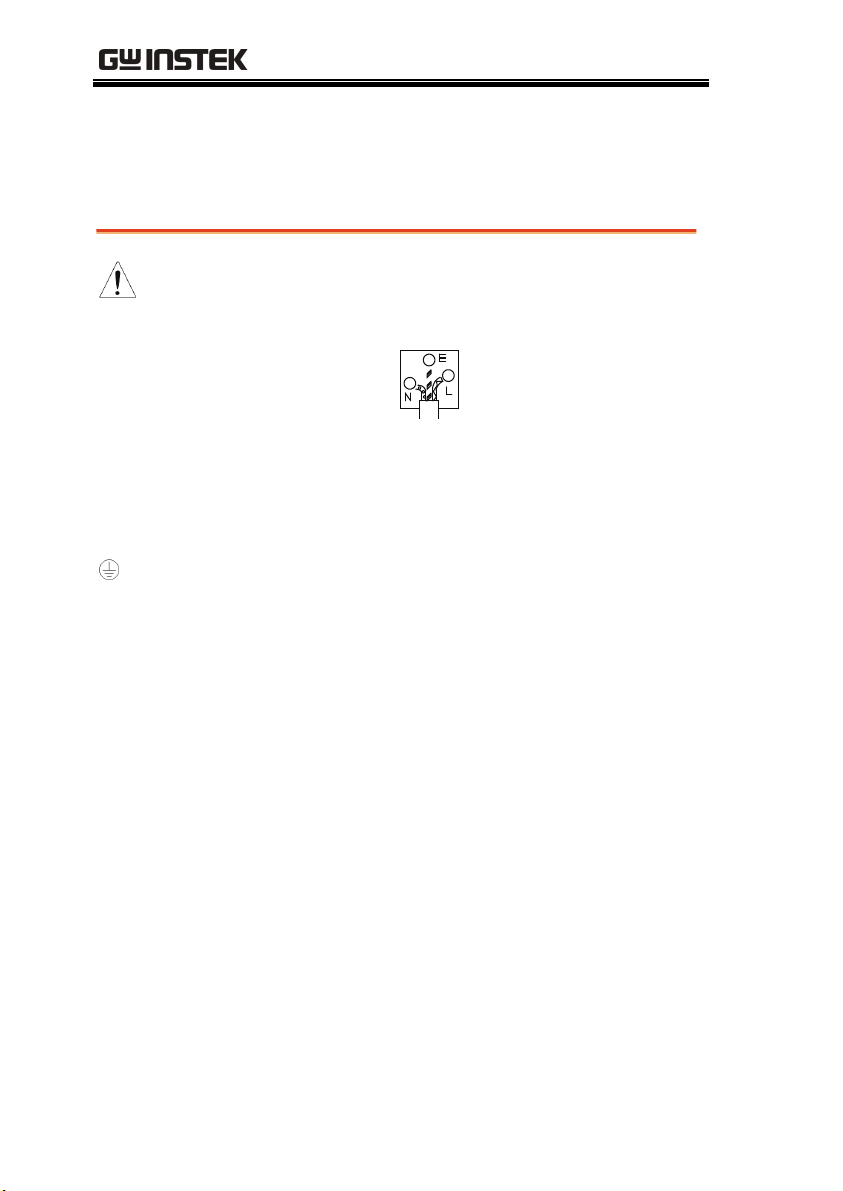
Power cord for the United Kingdom
When using the unit in the United Kingdom, make sure the power
cord meets the following safety instructions.
NOTE: This lead/appliance must only be wired by competent persons
WARNING: THIS APPLIANCE MUST BE EARTHED
IMPORTANT: The wires in this lead are coloured in accordance with the
following code:
Green/ Yellow: Earth
Blue:
Brown:
As the colours of the wires in main leads may not correspond with
the coloured marking identified in your plug/appliance, proceed
as follows:
The wire which is coloured Green & Yellow must be connected to
the Earth terminal marked with either the letter E, the earth symbol
or coloured Green/Green & Yellow.
The wire which is coloured Blue must be connected to the terminal
which is marked with the letter N or coloured Blue or Black.
The wire which is coloured Brown must be connected to the
terminal marked with the letter L or P or coloured Brown or Red.
If in doubt, consult the instructions provided with the equipment
or contact the supplier.
This cable/appliance should be protected by a suitably rated and
approved HBC mains fuse: refer to the rating information on the
equipment and/or user instructions for details. As a guide, a cable
of 0.75mm
2
should be protected by a 3A or 5A fuse. Larger
conductors would normally require 13A types, depending on the
connection method used.
Any exposed wiring from a cable, plug or connection that is
engaged in a live socket is extremely hazardous. If a cable or plug is
deemed hazardous, turn off the mains power and remove the cable,
any fuses and fuse assemblies. All hazardous wiring must be
immediately destroyed and replaced in accordance to the above
standard.
8
Neutral
Live (Phase)
Test Equipment Depot - 800.517.8431 - 99 Washington Street Melrose, MA 02176
TestEquipmentDepot.com

GETTING STARTED
GETTING STARTED
This chapter describes the GPM-8213 in a nutshell, including
accessories, package contents, its main features and front / rear
panel introduction.
Characteristics .......................................................... 10
Appearance ............................................................... 13
Front Panel ................................................................. 13
Display Overview ........................................................ 17
Rear Panel ................................................................... 20
Set Up ...................................................................... 22
Tilting the Stand ......................................................... 22
Power Up .................................................................... 23
Connect the wires to the GPM-8213 ......................... 24
9
GPM-8213 User Manual
Operation
Press the buttons on the front panel to easily
turn on the GPM-8213 measurement function.
All settings and measurements results are
displayed on the TFT-LCD screen panel for easy
use of each function.
Standard display mode: 2 main measurement
results and 6 secondary measurement results are
displayed in this screen.
Simple display mode: 4 major measurement
results are displayed in this screen.
Characteristics
The GPM-8213 is a high-precision, programmable power meter for
using in standby measuring the device with low power such as
switching power supplies, transformers, power supplies, adapter
and other devices. It equips with a color TFT-LCD screen which is
very convenient for reading the measurement results. The GPM8213 has become a reliable power measurement instruments
because of its simple operation, excellent performance and
automatic measurement interface.
10

GETTING STARTED
Performance
Features
6 selectable voltage ranges available from 15V to
300V with 0.1% of reading + 0.1% of range.
12 selectable current ranges available from 5mA
o 20A with 0.1% of reading + 0.1% of range.
t
It can even measure the voltage of abnormal
wave o
It can even measure the current of abnormal
wave o
Test terminals in the front panel.
Total harmonic distortion measurement.
Full five-digit measurement.
Voltage measurement range: 15V ~ 600V or
automat
Current measurement range: 5mA ~ 20A or
automat
Maximum accuracy of 0.1% of reading + 0.1% of
f CF 3. The half-range CF is up to 6.
f CF 3. The half-range CF is up to 6.
ic sw
itching
ic sw
itching
range
2 main measurement readings and 6 minor
measurement
screen o
4 main measurement readings are displayed in
readings are displayed in th
f standard display mode.
e
the screen of simple display mode.
Added stand-alone display of total harmonic
stortion measurement function (1
di
Test bandwidth of voltage and current: DC ~
z.
6kH
Added W-h power time integrator function
Selectable boot settings (Previous / Default)
The command set is conformed to
3 steps)
YOKOGAWA WT310E.
Interface
Tes
t Equipment Depot - 800.517.8431 - 99 Washington Street Melrose, MA 02176
Standard interface: USB / RS232 / LAN
Optional interface: GPIB
TestEquipmentDepot.com
11

GPM-8213 User Manual
Application
It can be applied to production test such as
power supplies, transformers, motors, electrical
equipment and other equipment with low
standby power.
It can be applied to power measurement
conforms to IEC 62301
It can be applied to assess the power
consumption of product design.
12
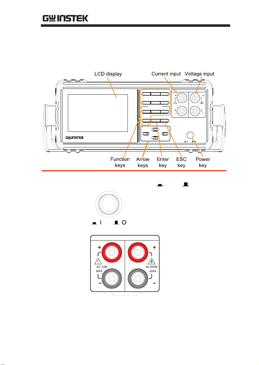
Appearance
R
Front Panel
GETTING STARTED
V −
MAX Hold
Dg tal Power Meter
GPM‐8213
Range I −Range
Key Lock
SetupMode
NTEGRATOR
StopStart Reset
Enter
Hod
ESCLocal
CURRENT VO AGE
I
AC 10A
MAX
I
CATII300V
POWER
AC 600V
V
MAX
V
Power Switch
POWE
Turns On or Off the main
power. For the power up sequence,
see page 23.
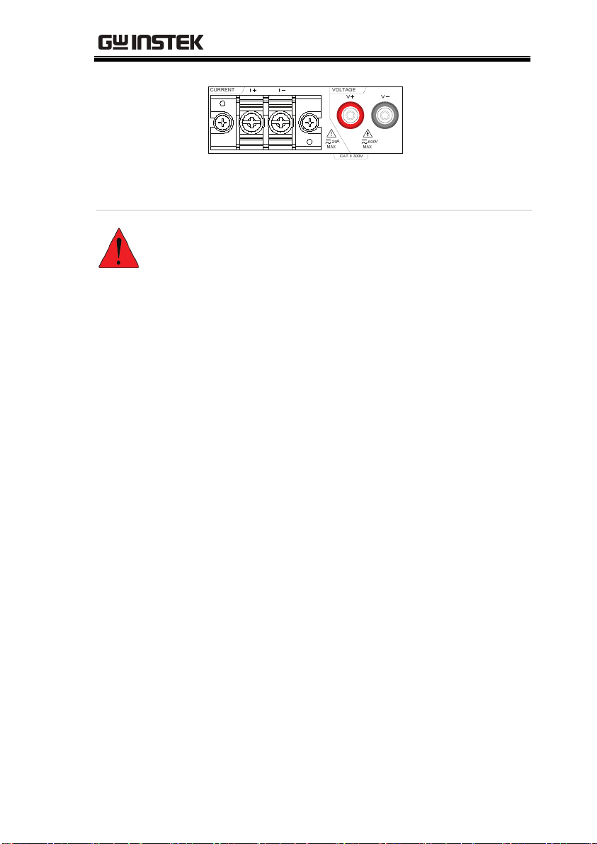
Current, Voltage
Te rm i na l s
CURRENT VOLTAGE
I
Current input: I+ and I–
terminals; Voltage
V
input: V+ and Vterminals.
I
CAT II 300V
V
13
Note
Warn ing
GPM-8213 User Manual
If the measurement power supply has
positive and negative electrode, please
connect + to the positive electrode of
power supply and - to the negative
electrode of power supply.
The maximum measurable current and
voltage are 600 V and 10A for voltage
and current terminals of the front
panel of the GPM-8213. Do not input
exceeded voltage and current,
otherwise it will burn the device.
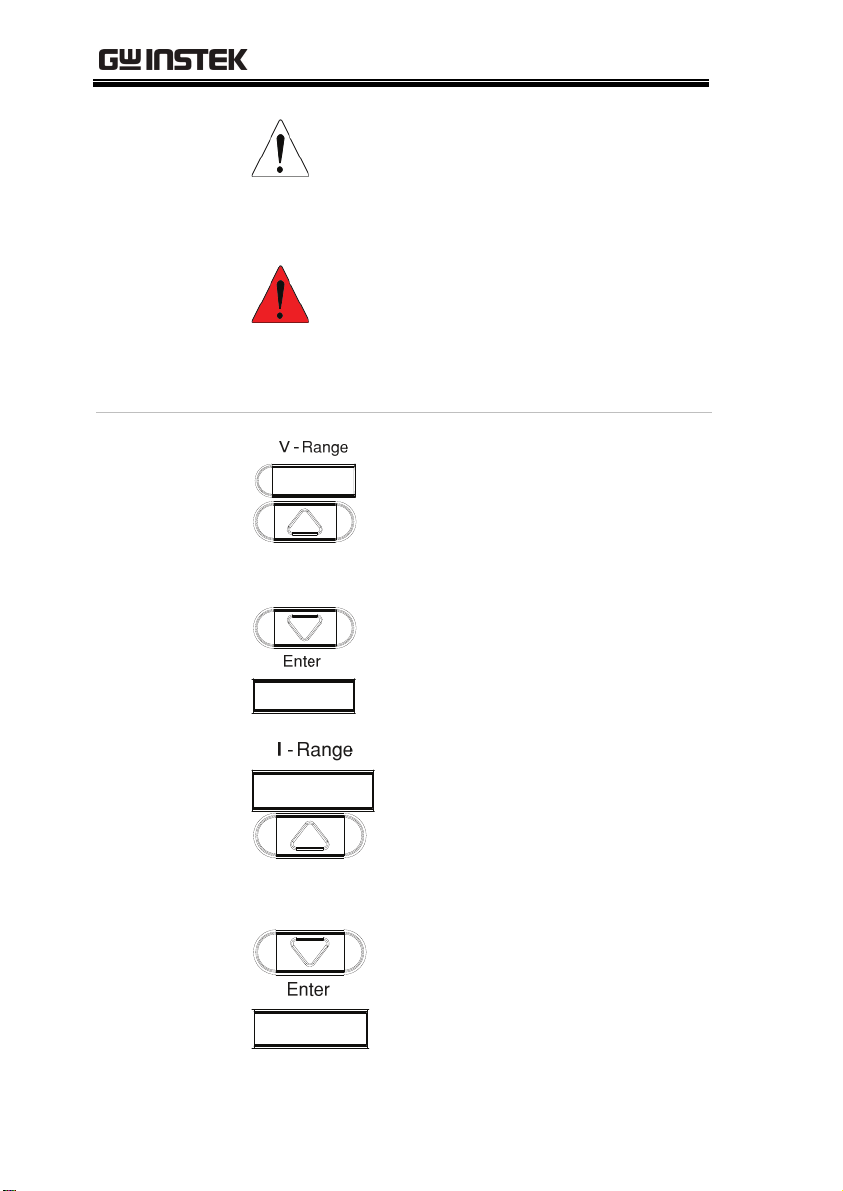
Function keys
V-Range key, up/down arrow keys
and Enter key can be used
o select a voltage range or auto
t
together
range measurement mode. See page
26.
I-Range key, up/down arrow keys
and Enter
key can be used
together
to select a current range or auto
range
measurement mode. See page
26.
14
Test Equipment Depot - 800.517.8431 - 99 Washington Street Melrose, MA 02176
TestEquipmentDepot.com
GETTING STARTED
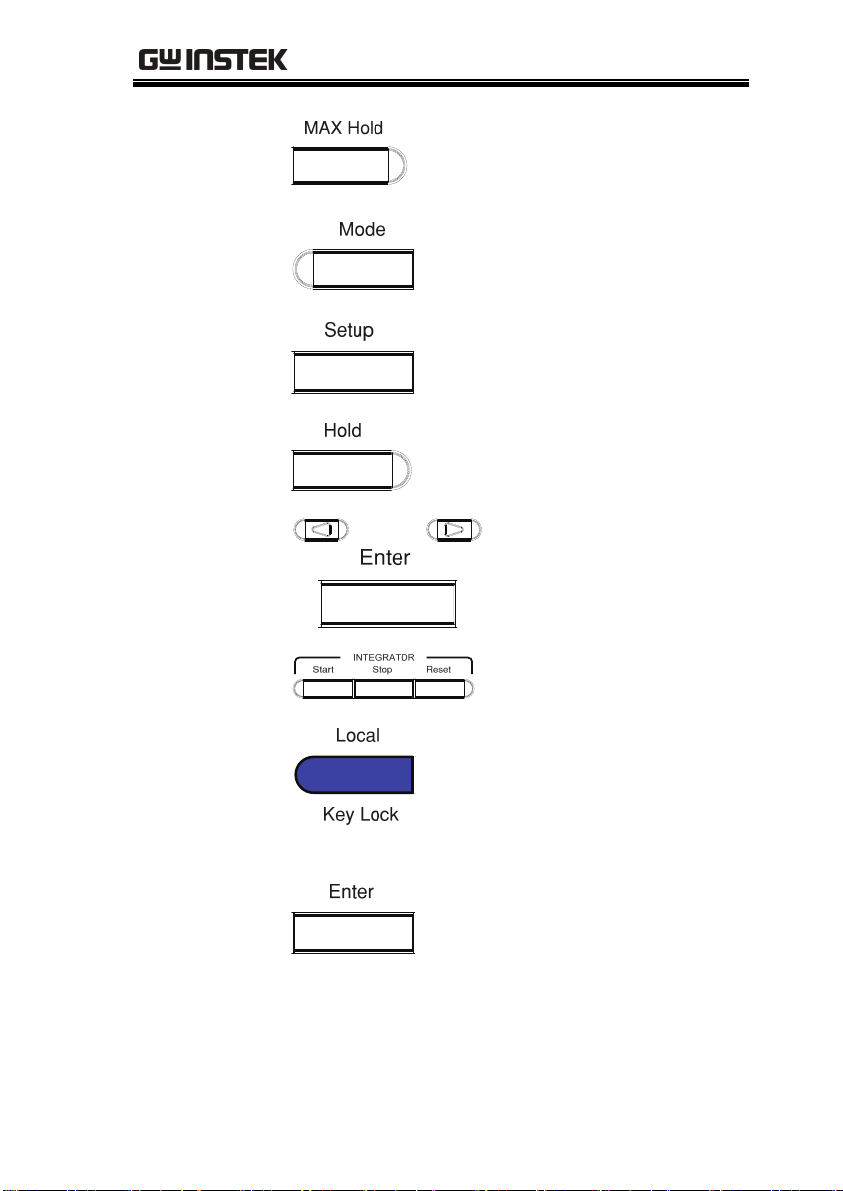
Press this button to display the
maximum measurement reading.
See page 48.
Press this key to select measure
mode (DC/AC/AC+DC). See page
48.
Press this key to enter the
measurement settings menu. See
page 30.
Press this key to switch window and
stop refreshing. See page 49.
Use the left and right arrow
keys to select Integrator
mode, and press Enter
button to enter the time
integrator function. See page
50.
Press this key to toggle to key lock.
In Remote control mode, press this
button to switch to local mode. See
page 49.
Confirm button
This button is used to enter the
menu, confirm the settings and
switch between the standard display
mode and simple display mode (no
function table and display icon). See
page 49.
15

GPM-8213 User Manual
Cancel (Exit)
button
Arrow Keys
Press this button to cancel the
current setting. The cursor returns to
the default position or return to the
previous menu according to the
situation. See page 49.
This for arrow keys are used
to edit the parameters,
browse the menu system
and select the parameter
range.
16
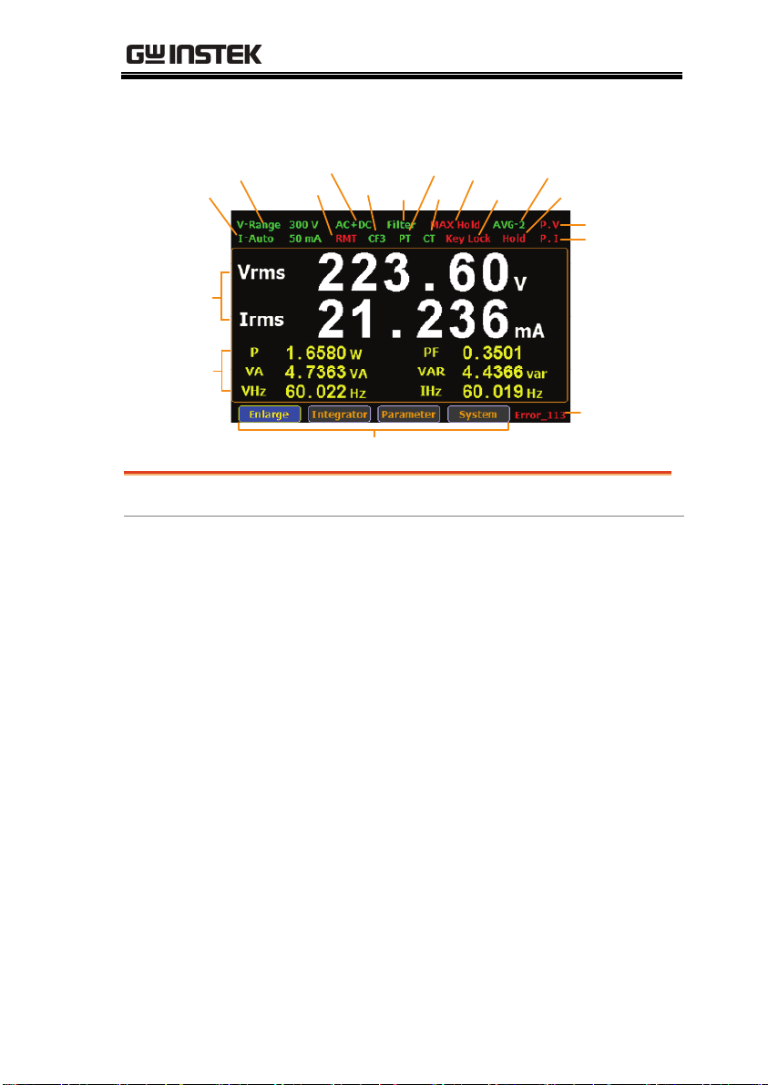
Display Overview
GETTING STARTED
Vo ltag e Ra nge
Current Range
Main
Measur emen t
Display
Minor
Measur emen t
Display
Item
Vol tage Range
Current Range
Mode
Remot e CF
Secondary Menus
FilterPTCT
Max. Hold
Status icon Description
V_Range 300V
Voltage measurement range.
Example here range is 300V.
V_Auto means that Auto Range is
turned on.
I_Auto 50mA
Current measurement range.
Example here range is 50mA.
Ke yLo ck
Average Range
Display Hold
Peak Volta ge
Pe ak Cu rrent
Remot e Error
I_Auto means that Auto Range is
turned on.
Mode
AC+DC
Measurement mode (AC, DC,
AC+DC)
Remote
Crest Factor
Filter
PT Ratio State
RMT Remote control mode (on/off)
CF3 Crest Factor (3/6)
Filter Voltage and current filters (on/off)
PT
External voltage magnification
(on/off)
Test Equipment Depot - 800.517.8431 - 99 Washington Street Melrose, MA 02176
TestEquipmentDepot.com
1
7

GPM-8213 User Manual
CT Ratio State
Maximum Hold
Keyboard Lock
Average
Display Hold
Peak Voltage
Peak Current
Remote Error
Standard Display
Mode
Simple Display
Mode
CT
External current magnification
(on/off)
Max. Hold
Retain and display the maximum
measurement reading.
KeyLock Lock Key button
Avg-1
Average number of sampling
(1/2/4/8/16/32/64)
Hold
Retain and display the current
measurement reading.
P.V
The voltage exceeds the
measurement range
P.I
The current exceeds the
measurement range
Err-XXX
An error occurs in remote
command
Display the measurement result of 2 major and 6
minor measurement parameters
Display the measurement result of 4 major
measurement parameters
Secondary menus
Display secondary function menu
Enlarge
This function key is used to switch
display of measurement result from 2
major plus 6 minor to 4 major ones.
Integrator
This function key is used to set up
integrator measurement parameters
and execute integrator measurement
function.
Parameter
This function key is used set up
measurement parameters.
18

GETTING STARTED
System
This function key is used to enter the
system setting and system
configuration screens.
19
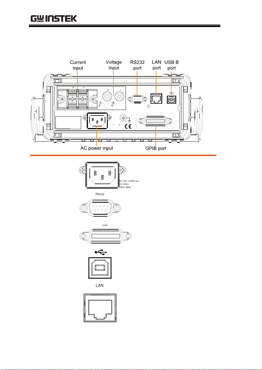
Rear Panel
CURRENT VOLTAGE
SER.NO. LABEL
I I
MAX
20A
V V
CATI300V
AC
100 240V
50 / 60Hz
25VA MAX
GPM-8213 User Manual
R 232
600V
MAX
REMOVE N PUTS BEFORE OPENING.
L N
WARNING
TO AVOID SHOCK,
GPB
Power Cord
Socket
Accepts the power cord.
AC 100~240V ±10%,
50/60Hz
RS232
RS232 port. This port is used for
remote control.
GPIB port (Option).
USB Device Port
Type B USB port. This port is used
for remote control.
LAN Port
20
Test Equipment Depot - 800.517.8431 - 99 Washington Street Melrose, MA 02176
TestEquipmentDepot.com
LAN Port.
GETTING STARTED
Rear
Voltage/Current
input terminal
Warn ing
Rear
Voltage/Current
input terminals is
used to connect
the main
measurement
signals.
Do not use damaged device. Before using the
equipment, check its housing first to sure there is
no any cracks. Do not operate this device in an
environment containing explosive gases, steam or
dust.
The maximum measurable current and voltage are
600 V and 20A for voltage and current terminals of
the rear panel of the GPM-8213. Do not input
exceeded voltage and current, otherwise it will burn
the device.
Always use the supplied cable for connection.
Before connecting the device, observe all the safety
symbols marked on the device.
Turn off the power to the device and the application
system before connecting I/O terminals.
Do not install replacement parts on the device or
perform any unauthorized modifications.
Do not use this device if the removable cover is
removed or loosened.
Do not connect any cables and terminals before
performing self-test.
Use only the power adapter supplied by the
manufacturer to avoid accidental injury.
Do not use this device for life support systems or
any other equipment that has safety requirements.
21
 Loading...