


 Loading...
CE Approved GSI/FFI Portable
Dryer Manual
Operation Manual
PNEG-1717
Date: 12-08-10
PNEG-1717

Models:
1100 Series (Models 1108, 1112, 1114, 1116, 1118, 1120, 1122, 1126, CFAB190, CFAB270, CFAB320, CFAB370, CFAB400, CFAB460, CFAB510, CFAB511, CFAB601)
1200 Series (Models 1214, 1216, 1218, 1220, 1222, 1226, C2120A, C2122A, C2125A, C2130A, C2132A, C2140A)
1200S Series (Models 1214S, 1218S, 1220S, 1222S, 1226S, CF2141, CF2181, CF500H, CF2221, CF650M)
2300 Series (Models 2314, 2318, 2320, 2322, 2326, CF3142, CF3182, CF3202, CF3222, CF3262)
2400 Series (Models 2420, 2426, CF1000H, CF1300M)
3400 Series (Models 3414, 3418, 3420, 3422, 3426, CF4143, CF4183, CF4203, CF4223, CF4263)
3600 Series (Models 3620, 3626, CF1500H, CF2000M)
X-Stream Configuration - Uses same model numbers (and components) as listed above. The only difference is that the fans are pointed in different directions.
2 |
PNEG-1717 CE Approved GSI/FFI Portable Dryer Manual |

|
Table of Contents |
Contents |
|
Chapter 1 Introduction .......................................................................................................................................... |
5 |
Dryer Operation ..................................................................................................................................... |
5 |
Precautions ........................................................................................................................................... |
5 |
Chapter 2 Safety ..................................................................................................................................................... |
6 |
Safety Guidelines .................................................................................................................................. |
6 |
Emergency Stop Switch ........................................................................................................................ |
7 |
Chapter 3 Installation ............................................................................................................................................ |
8 |
Transporting/Single Fan ........................................................................................................................ |
8 |
Location of the Dryer ............................................................................................................................. |
9 |
Foundation ............................................................................................................................................ |
9 |
Supporting the Dryer ............................................................................................................................. |
9 |
Anchor Points ........................................................................................................................................ |
9 |
Wet/Dry Grain ....................................................................................................................................... |
9 |
Electrical Power Supply ...................................................................................................................... |
10 |
Fuel ..................................................................................................................................................... |
11 |
Chapter 4 Specifications ..................................................................................................................................... |
13 |
FFI Dimensions ................................................................................................................................... |
13 |
FFI Specifications ................................................................................................................................ |
15 |
GSI Dimensions .................................................................................................................................. |
17 |
GSI Specifications ............................................................................................................................... |
19 |
All Stack Dimensions .......................................................................................................................... |
21 |
All Stack Specifications ....................................................................................................................... |
24 |
Stack Dryer Foundation Specifications ............................................................................................... |
28 |
Chapter 5 Vision Control Panel .......................................................................................................................... |
29 |
Vision Control Panel Layout ................................................................................................................ |
29 |
Control Power Switch .......................................................................................................................... |
29 |
Fan Switch .......................................................................................................................................... |
29 |
Heater Switch ...................................................................................................................................... |
30 |
Load Auger Switch .............................................................................................................................. |
30 |
Unload Switch ..................................................................................................................................... |
30 |
Outside Light Switch ........................................................................................................................... |
30 |
Start Switch ......................................................................................................................................... |
30 |
Stop Switch ......................................................................................................................................... |
30 |
Chapter 6 Vision Touch Screen Display ............................................................................................................ |
31 |
Boot Screen ........................................................................................................................................ |
31 |
Chapter 7 Vision Test Firing ............................................................................................................................... |
32 |
Dryer Pre-Season Checks .................................................................................................................. |
32 |
Burner Test Fire .................................................................................................................................. |
33 |
Dryer Shut Down ................................................................................................................................. |
35 |
Emergency .......................................................................................................................................... |
35 |
Chapter 8 Vision/Dri-Tek Dryer Operation ......................................................................................................... |
36 |
Full Heat Drying .................................................................................................................................. |
36 |
Final Moisture ...................................................................................................................................... |
36 |
Drying Temperatures .......................................................................................................................... |
36 |
Initial Setup Parameters ...................................................................................................................... |
36 |
Timer and Delay Settings .................................................................................................................... |
36 |
Setting the Temperatures ...................................................................................................... |
.............. 36 |
Start-Up ............................................................................................................................................... |
36 |
Continuous Flow Drying Mode Using Regulation of Grain Temperature ............................................ |
37 |
Continuous Flow Drying Mode Using Regulation of Moisture: 5 MR SP ............................................ |
41 |
PNEG-1717 CE Approved GSI/FFI Portable Dryer Manual |
3 |

Table of Contents |
|
Chapter 9 Vision Illustrations ............................................................................................................................. |
44 |
Supply Line (LP Shown) ...................................................................................................................... |
44 |
28" and 36" LP 1" NPT CE Pipe Train Assembly ................................................................................ |
45 |
40" and 42" LP 1-1/2" NPT CE Pipe Train Assembly .......................................................................... |
45 |
LP Vaporizer Coil Adjustment ............................................................................................................. |
46 |
28" and 36" LP/NG 1" NPT CE Pipe Train Assembly ......................................................................... |
47 |
Vision Fan/Heater Control Box ............................................................................................................ |
49 |
Top Auger Drive .................................................................................................................................. |
49 |
Discharge Safety Switch ..................................................................................................................... |
50 |
Meter Roll Speed Sensor .................................................................................................................... |
50 |
Vision Upper Control Box .................................................................................................................... |
51 |
Vision Control Panel (Rear) ................................................................................................................ |
52 |
Vision Lower Control Box (Back Panel) .............................................................................................. |
53 |
Chapter 10 Service ............................................................................................................................................... |
54 |
Seasonal Inspection/Service ............................................................................................................. |
54 |
Lubrication Procedure ....................................................................................................................... |
56 |
Fan Blade Removal and Installation .................................................................................................. |
57 |
Fan Motor Removal and Installation .................................................................................................. |
57 |
Heater Parts Removal and Installation .............................................................................................. |
58 |
Metering Roll Servicing ...................................................................................................................... |
58 |
Main Controls .................................................................................................................................... |
58 |
How to Clear a Jammed Meter Roll (All Power “OFF”) ...................................................................... |
58 |
Chapter 11 Vision Schematics and Wiring Diagrams ....................................................................................... |
59 |
Fan/Heater Standard ......................................................................................................................... |
59 |
Front Panel ........................................................................................................................................ |
60 |
Upper Control Box ............................................................................................................................. |
82 |
380-400 VAC 3 Phase ....................................................................................................................... |
83 |
Ladder Diagram ................................................................................................................................. |
84 |
Chapter 12 Warranty ............................................................................................................................................ |
87 |
4 |
PNEG-1717 CE Approved GSI/FFI Portable Dryer Manual |

1. Introduction
Dryer Operation
Thank you for choosing a CE Approved GSI/FFI Vision Series Grain Dryers. Please read this manual before installing or operating the equipment.
Make sure you and your employees understand all requirements, hazards and precautions associated with this equipment. Failure to do so could result in SERIOUS INJURY or DEATH.
Ensure you have the correct power and fuel supply for the dryer. Do not alter or modify this equipment.
Follow all local directives, codes and regulations when installing this equipment. Authorities having jurisdiction should be consulted before installations are made.
Precautions
1.Keep ALL guards, safety decals and safety devices in place. NEVER operate with guards removed.
2.Restrict access to trained persons only.
3.NEVER bypass safety devices.
4.Switch OFF and LOCK all power and fuel before entering, servicing or accessing the equipment.
5.Follow all servicing instructions.
6.Keep the dryer CLEAN.
7.DO NOT exceed maximum temperatures or pressures.
8.Drying unclean grain will reduce the performance of the dryer and can cause fires.
9.CAUTION Equipment on the dryer can START AUTOMATICALLY.
10.Feed and discharge equipment must match dryer throughput.
11.DO NOT allow foreign material to be drawn into the fan.
12.When drying products not included in this manual refer to GSI for further precautions and instructions.
13.Check for leaks at least every day. Repair before operation.
Use Caution in the Operation of this Equipment
This dryer is designed and manufactured with operator safety in mind. However, residual hazards remain due to the nature of grain drying. Use extreme caution at all times.
Keep the dryer clean.
PNEG-1717 CE Approved GSI/FFI Portable Dryer Manual |
5 |

2. Safety
Safety Guidelines
Please observe all safety decals on the equipment.
Safety decals on this equipment use the following system:
HAZARD
Example: Rotating auger
PROHIBITION
Example: No smoking or naked flames
MANDATORY ACTION
Example: Wear ear defenders
Instructions for your safety
6 |
PNEG-1717 CE Approved GSI/FFI Portable Dryer Manual |

2. Safety
Emergency Stop Switch
In event of emergency press the Emergency Stop to stop all dryer equipment (power remains connected).
PNEG-1717 CE Approved GSI/FFI Portable Dryer Manual |
7 |
3. Installation
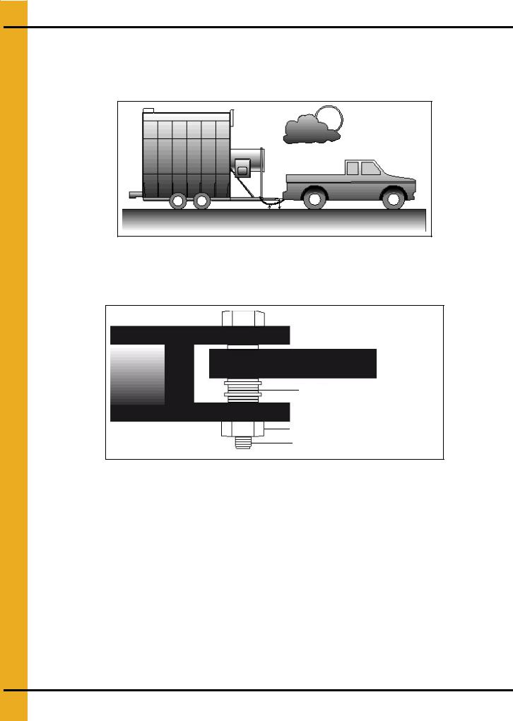
Transporting/Single Fan
When transporting the unit by truck or tractor observe these precautions: 1. Hitch height is 350 mm-430 mm. (See Figure 3A.)
Figure 3A
2.Hitch pin diameter is 19 mm minimum. Must be securely fastened. (See Figure 3B.)
3.Minimize hitch movement. (See Figure 3B.)
Washers
Locking nut
19 mm Minimum diameter
Figure 3B
4.Use a safety chain. (See Figure 3A.)
5.Dryer must be empty and towed in accordance with all applicable laws and regulations.
6.Tyre pressure should be 3.8 bar.
7.Maximum towing speed is lowest of 70 km/h or statutory speed limit.
8.After first 80 km and every 300 km check:
a.Wheel bearing temperature <= 65°C.
b.Wheel nuts torque = 160 Nm.
8 |
PNEG-1717 CE Approved GSI/FFI Portable Dryer Manual |

3. Installation
Location of the Dryer
Consider:
1.Wet and dry storage.
2.Access to power and fuel.
3.Proximity to other structures (maintain minimum 1m clearance).
4.Noise.
5.Over head power.
Always install out of doors.
Foundation
1.Dryers should be installed on a suitable concrete base/foundation.
2.Foundation design to be carried out by qualified engineer.
3.Take into account ground and weather conditions.
4.Refer to dryer dimensions and loaded weights in table on Pages 11-25.
Supporting the Dryer
1.Wheels are for transport only.
2.Support under the hitch (drawbar removed).
3.Support every 2m on both sides.
4.Ensure the dryer is level in all directions.
5.Ensure supports can carry the full weight of the dryer.
6.Allow 400 mm clearance under the dryer for cleaning.
Anchor Points
Anchor to the concrete slab to ensure stability against high winds.
Wet/Dry Grain
Wet Grain Supply
1.Wet grain supply to the dryer intake may be gravity or powered auger/conveyor.
2.Powered fill equipment can be connected via the contactor provided in the dryer control box.
3.After the initial fill the system will run to maintain the dryer level.
4.Dryer fill is monitored by the out of grain timer. (Refer to PNEG-1710 for setting this timer.)
5.Dryer shuts down when out of grain.
PNEG-1717 CE Approved GSI/FFI Portable Dryer Manual |
9 |

3. Installation
Dry Grain Removal
1.Dry grain discharges at the rear of the dryer (front discharge optional).
2.Dry grain removal may be electrically connected to contactor provided in the main control box.
Electrical Power Supply
Ensure there is adequate electrical power to run the dryer. All supplies are 3 phase with neutral and include a protective earth.
NOTE: Excessive voltage drops can cause equipment malfunction. Size supply and conductors to ensure maximum 5% voltage drop under all start and run conditions.
Power Supply Disconnect
Supply connections are made at the main power disconnect on the upper control box.
Machine to Earth Grounding
1.The dryer must be connected to an adequate earth connection.
2.This must be carried out and tested in accordance with EU Directives, local regulations, codes and EN60204 “Electrical Equipment of Machines”.
3.Failure to do so will result in equipment malfunction and can result in a dangerous fault condition.
4.Electrical supplies from generators must also include adequate, tested earth connection supplied by the generator installer.
5.A 2.4m copper ground rod, supplied with the dryer must be installed in accordance with local regulations.
Connecting Auxiliary Conveyors
Load and discharge conveyors connected into the dryer must not exceed electrical load information in
Specifications Chapter on Pages 15-25.
Motors exceeding these must be powered separate from the dryer with separate contactor and overload device for each motor. Control may still be performed by the dryer.
10 |
PNEG-1717 CE Approved GSI/FFI Portable Dryer Manual |
3. Installation
Fuel
Liquid Propane (LP)
Liquid Draw
1.LPG is vaporized internally within the dryer.
2.LPG pipework and controls from the tank to the dryer must be installed by the gas supplier in accordance with local directives, laws, codes and regulations.
3.LPG tank should be sized to supply the full heat input of all burners. See heater rating plates for details.
Fuel System Specifications and Recommendations (LP) Liquid Propane
Dryer |
Maximum Heat |
Maximum Fuel |
Fuel Line |
Heater Orifice Diameter mm ** |
|
(U = Upper, L = Lower, Heater Position) |
|||||
Model # |
Capacity kW |
Flow l/h |
Size mm * |
||
(T = Top, M = Middle, B = Base Dryer Module) |
|||||
|
|
|
|
||
|
|
|
|
|
|
1108/190 |
880 |
131 |
15 |
7.8 |
|
1112/270 |
1320 |
195 |
15 |
9.6 |
|
|
|
|
|
|
|
1114/320 |
1685 |
250 |
15 |
10.9 |
|
1116/370 |
1685 |
250 |
15 |
10.9 |
|
1118/400 |
2052 |
302 |
15 |
12.0 |
|
1120/460 |
2200 |
326 |
15 |
12.4 |
|
|
|
|
|
|
|
1122/511 |
2491 |
370 |
22 |
13.2 |
|
1126/601 |
2785 |
414 |
22 |
13.9 |
|
|
|
|
|
|
|
1214/2120 |
1700 |
250 |
22 |
(U)8.8 (L)6.8 |
|
1216 |
1993 |
294 |
22 |
(U)10.2 (L)6.8 |
|
1218/2125 |
1993 |
292 |
22 |
(U)10.2 (L)6.8 |
|
1220/2130 |
2565 |
382 |
22 |
(U)10.7 (L)7.8 |
|
|
|
|
|
|
|
1222 |
2931 |
434 |
22 |
(U)11.7 (L)7.8 |
|
1226/2140 |
3078 |
458 |
22 |
(U)12.2 (L)7.8 |
|
|
|
|
|
|
|
1214S/2141 |
2052 |
302 |
22 |
(U+L) 8.8 |
|
1218S/2181 |
2638 |
390 |
22 |
(U+L) 10.3 |
|
1220S/500H |
3371 |
501 |
22 |
(U+L) 10.7 |
|
1222S/2221 |
4104 |
609 |
22 |
(U+L) 11.7 |
|
|
|
|
|
|
|
1226S/650M |
4397 |
653 |
22 |
(U+L) 12.2 |
|
2314/3142 |
3445 |
510 |
22 |
T 10.7 B (U+L) 7.8 |
|
|
|
|
|
|
|
2318/3182 |
4104 |
609 |
22 |
T 11.7 B (U+L) 8.8 |
|
2320/3202 |
4837 |
717 |
22 |
T 12.2 B (U+L) 10.2 |
|
2322/3222 |
5130 |
760 |
22 |
T 13.7 B (U+L) 10.2 |
|
2326/3262 |
7183 |
1063 |
22 |
T 14.2 B (U+L) 11.2 |
|
2420/1000H |
5277 |
784 |
22 |
(T+B, U+L) 10.2 |
|
2426/1300M |
7622 |
1130 |
22 |
(T+B, U+L) 11.2 |
|
|
|
|
|
|
|
3414/4143 |
5130 |
760 |
22 |
T 10.8 M 10.8 B (U+L) 7.8 |
|
3418/4183 |
6156 |
911 |
22 |
T 11.7 M 11.7 B (U+L) 8.8 |
|
|
|
|
|
|
|
3420/4203 |
7036 |
1043 |
22 |
T 12.2 M 12.2 B (U+L) 10.2 |
|
3422/4223 |
7622 |
1130 |
22 |
T 13.7 M 13.7 B (U+L) 8.3 |
|
|
|
|
|
|
|
3426/4263 |
9381 |
1389 |
22 |
T 14.2 M 14.2 B (U+L) 11.2 |
|
3620/1500H |
7915 |
1174 |
22 |
(T+M+B, U+L) 10.2 |
|
|
|
|
|
|
|
3626/2000M |
11433 |
1646 |
22 |
(T+M+B, U+L) 11.2 |
|
|
|
|
|
|
* Maximum line size for 30m length. ** Maximum burner pressure 450 mBar.
PNEG-1717 CE Approved GSI/FFI Portable Dryer Manual |
11 |

3. Installation
Natural Gas (N)
Gas Volume and Pressure
Natural gas supply should offer:
1.49 MJ/m3 calorific value.
2.650 mBar supply pressure. (Lower pressure may inhibit dryer performance.)
3.Gas pipework and controls from the supply to the dryer must be installed by the gas supplier in accordance with local directives, laws, codes and regulations.
Check the supply capacity against dryer requirements. (See heater rating plates for details.)
Fuel System Specifications and Recommendations (NG) Natural Gas
Dryer |
Maximum Heat |
Maximum Fuel Flow |
Fuel Line Size |
Heater Orifice Diameter mm ** |
|
(U = Upper, L = Lower, Heater Position) |
|||||
Model # |
Capacity kW |
m3/h |
mm * |
||
(T = Top, M = Middle, B = Base Dryer Module) |
|||||
|
|
|
|
||
|
|
|
|
|
|
1108/190 |
880 |
82 |
32 |
9.7 |
|
1112/270 |
1320 |
123 |
38 |
11.9 |
|
|
|
|
|
|
|
1114/320 |
1685 |
157 |
38 |
13.3 |
|
1116/370 |
1685 |
157 |
38 |
13.2 |
|
|
|
|
|
|
|
1118/400 |
2052 |
188 |
50 |
14.1 |
|
1120/460 |
2200 |
206 |
50 |
14.9 |
|
|
|
|
|
|
|
1122/511 |
2491 |
233 |
50 |
15.3 |
|
1126/601 |
2785 |
261 |
50 |
16.5 |
|
1214/2120 |
1700 |
158 |
38 |
(U)10.5 (L)8.1 |
|
1216 |
1993 |
186 |
50 |
(U)12.9 (L)8.1 |
|
1218/2125 |
1993 |
186 |
50 |
(U)12.9 (L)8.1 |
|
1220/2130 |
2565 |
239 |
50 |
(U)13.3 (L)8.1 |
|
|
|
|
|
|
|
1222 |
2931 |
273 |
50 |
(U)13.3 (L)8.1 |
|
1226/2140 |
3078 |
287 |
50 |
(U)14.1 (L)8.1 |
|
1214S/2141 |
2052 |
191 |
38 |
(U+L) 10.5 |
|
1218S/2181 |
2638 |
246 |
38 |
(U+L) 12.9 |
|
|
|
|
|
|
|
1220S/500H |
3371 |
314 |
50 |
(U+L) 13.3 |
|
1222S/2221 |
4104 |
316 |
50 |
(U+L) 14.1 |
|
1226S/650M |
4397 |
410 |
50 |
(U+L) 14.9 |
|
2314/3142 |
3445 |
321 |
50 |
T 13.3 B (U+L) 9.7 |
|
2318/3182 |
4104 |
316 |
50 |
T 14.1 B (U+L) 10.5 |
|
2320/3202 |
4837 |
451 |
80 |
T 14.9 B (U+L) 12.9 |
|
|
|
|
|
|
|
2322/3222 |
5130 |
478 |
80 |
T 15.3 B (U+L) 12.9 |
|
2326/3262 |
7183 |
669 |
80 |
T 16.6 B (U+L) 13.7 |
|
2420/1000H |
5277 |
492 |
80 |
(T+B, U+L) 12.9 |
|
2426/1300M |
7622 |
710 |
80 |
(T+B, U+L) -13.7 |
|
3414/4143 |
5130 |
478 |
80 |
T 13.3 M 13.3 B (U+L) 9.7 |
|
3418/4183 |
6156 |
574 |
80 |
T 14.1 M 14.1 B (U+L) 10.5 |
|
3420/4203 |
7036 |
656 |
80 |
T 14.9 M 14.9 B (U+L) 12.9 |
|
3422/4223 |
7622 |
710 |
80 |
T 15.3 M 15.3 B (U+L) 12.9 |
|
3426/4263 |
9381 |
874 |
80 |
T 16.6 M 16.6 B (U+L) 13.7 |
|
3620/1500H |
7915 |
738 |
80 |
(T+M+B, U+L) 12.9 |
|
|
|
|
|
|
|
3626/2000M |
11433 |
1065 |
80 |
(T+<M+B, U+L) 13.7 |
|
* Maximum line size for a 100' distance. ** Maximum burner pressure 450 mBar. |
|
||||
12 |
PNEG-1717 CE Approved GSI/FFI Portable Dryer Manual |

4. Specifications
FFI Dimensions
Figure 4A
Figure 4B
PNEG-1717 CE Approved GSI/FFI Portable Dryer Manual |
13 |

4. Specifications
Single Module FFI Transport and Installation Dimensions
Values are Valid for Transportation of Stack Modules
|
|
A |
B |
|
C |
D |
E |
F |
G |
H |
|
|
|
|
|
|
|
|
|
|
|
||
|
Dryer |
Transport |
Installed |
Installed Height |
Height w/o |
Frame |
Transport |
Installed |
Transport |
||
|
Basket |
|
|
||||||||
|
Wet |
Standard |
|||||||||
|
|
Height |
Width |
Wet Bin |
Width |
Width |
Length |
Length |
|||
|
|
|
|
Bin |
Top |
|
|
|
|
|
|
|
|
|
|
|
|
|
|
|
|
|
|
|
190T (10') |
3632.2 |
2438.4 |
3962.4 |
3505.2 |
3124.2 |
1955.8 |
2438.4 |
5232.4 |
5842.0 |
|
|
(11' 11") |
(8') |
(13') |
(11' 6") |
(10' 3") |
(6' 5") |
(8') |
(17' 2") |
(19' 2") |
||
|
|
||||||||||
|
|
|
|
|
|
|
|
|
|
|
|
|
270 (12') |
4089.4 |
2438.4 |
4419.6 |
3962.4 |
3581.4 |
1955.8 |
2438.4 |
5842.0 |
6451.6 |
|
|
(13' 5") |
(8') |
(14' 6") |
(13') |
(11' 9") |
(6' 5") |
(8') |
(19' 2") |
(21' 2") |
||
|
|
||||||||||
|
|
|
|
|
|
|
|
|
|
|
|
|
320 (14') |
4089.4 |
2438.4 |
4419.6 |
3962.4 |
3581.4 |
1955.8 |
2438.4 |
6451.6 |
7061.2 |
|
|
(13' 5") |
(8') |
(14' 6") |
(13') |
(11' 9") |
(6' 5") |
(8') |
(21' 2") |
(23' 2") |
||
|
|
||||||||||
|
|
|
|
|
|
|
|
|
|
|
|
|
370 (16') |
4089.4 |
2438.4 |
4419.6 |
3962.4 |
3581.4 |
1955.8 |
2438.4 |
7061.2 |
7670.8 |
|
1 Fan CFAB |
(13' 5") |
(8') |
(14' 6") |
(13') |
(11' 9") |
(6' 5") |
(8') |
(23' 2") |
(25' 2") |
||
|
|||||||||||
|
|
|
|
|
|
|
|
|
|
||
Series Dryers |
400 (18') |
4089.4 |
2438.4 |
4419.6 |
3962.4 |
3581.4 |
1955.8 |
2438.4 |
7670.8 |
8280.4 |
|
|
|||||||||||
|
(13' 5") |
(8') |
(14' 6") |
(13') |
(11' 9") |
(6' 5") |
(8') |
(25' 2") |
(27' 2") |
||
|
|
||||||||||
|
|
|
|
|
|
|
|
|
|
|
|
|
460 (20') |
4089.4 |
2438.4 |
4419.6 |
3962.4 |
3581.4 |
1955.8 |
2438.4 |
8280.4 |
8890.0 |
|
|
(13' 5") |
(8') |
(14' 6") |
(13') |
(11' 9") |
(6' 5") |
(8') |
(27' 2") |
(29' 2") |
||
|
|
||||||||||
|
|
|
|
|
|
|
|
|
|
|
|
|
511 (22') |
4089.4 |
2438.4 |
4419.6 |
3962.4 |
3581.4 |
1955.8 |
2438.4 |
8890.0 |
9499.6 |
|
|
(13' 5") |
(8') |
(14' 6") |
(13') |
(11' 9") |
(6' 5") |
(8') |
(29' 2") |
(31' 2") |
||
|
|
||||||||||
|
|
|
|
|
|
|
|
|
|
|
|
|
601 (26') |
4089.4 |
2438.4 |
4419.6 |
3962.4 |
3581.4 |
1955.8 |
2438.4 |
10109.2 |
10718.8 |
|
|
(13' 5") |
(8') |
(14' 6") |
(13') |
(11' 9") |
(6' 5") |
(8') |
(33' 2") |
(35' 2") |
||
|
|
||||||||||
|
|
|
|
|
|
|
|
|
|
|
|
|
320 (14') |
4089.4 |
2641.6 |
4419.6 |
3962.4 |
3581.4 |
1955.8 |
2438.4 |
6451.6 |
7061.2 |
|
|
(13' 5") |
(8' 8") |
(14' 6") |
(13') |
(11' 9") |
(6' 5") |
(8') |
(21' 2") |
(23' 2") |
||
|
|
||||||||||
|
|
|
|
|
|
|
|
|
|
|
|
|
410 (18') |
4089.4 |
2641.6 |
4419.6 |
3962.4 |
3581.4 |
1955.8 |
2438.4 |
7670.8 |
8280.4 |
|
2 Fan CFAB |
(13' 5") |
(8' 8") |
(14' 6") |
(13') |
(11' 9") |
(6' 5") |
(8') |
(25' 2") |
(27' 2") |
||
|
|||||||||||
|
|
|
|
|
|
|
|
|
|
||
Series Dryers |
510 (22') |
4089.4 |
2641.6 |
4419.6 |
3962.4 |
3581.4 |
1955.8 |
2438.4 |
8890.0 |
9499.6 |
|
|
|||||||||||
|
(13' 5") |
(8' 8") |
(14' 6") |
(13') |
(11' 9") |
(6' 5") |
(8') |
(29' 2") |
(31' 2") |
||
|
|
||||||||||
|
|
|
|
|
|
|
|
|
|
|
|
|
600 (26') |
4089.4 |
2641.6 |
4419.6 |
3962.4 |
3581.4 |
1955.8 |
2438.4 |
10109.2 |
10718.8 |
|
|
(13' 5") |
(8' 8") |
(14' 6") |
(13') |
(11' 9") |
(6' 5") |
(8') |
(33' 2") |
(35' 2") |
||
|
|
||||||||||
|
|
|
|
|
|
|
|
|
|
|
|
|
2120 (14') |
4089.4 |
2438.4 |
4419.6 |
3962.4 |
3581.4 |
1955.8 |
2438.4 |
6451.6 |
7061.2 |
|
|
(13' 5") |
(8') |
(14' 6") |
(13') |
(11' 9") |
(6' 5") |
(8') |
(21' 2") |
(23' 2") |
||
|
|
||||||||||
|
|
|
|
|
|
|
|
|
|
|
|
|
2122 (16') |
4089.4 |
2438.4 |
4419.6 |
3962.4 |
3581.4 |
1955.8 |
2438.4 |
7061.2 |
7670.8 |
|
|
(13' 5") |
(8') |
(14' 6") |
(13') |
(11' 9") |
(6' 5") |
(8') |
(23' 2") |
(25' 2") |
||
|
|
||||||||||
|
|
|
|
|
|
|
|
|
|
|
|
|
2125 (18') |
4089.4 |
2438.4 |
4419.6 |
3962.4 |
3581.4 |
1955.8 |
2438.4 |
7670.8 |
8280.4 |
|
C2100A |
(13' 5") |
(8') |
(14' 6") |
(13') |
(11' 9") |
(6' 5") |
(8') |
(25' 2") |
(27' 2") |
||
|
|||||||||||
|
|
|
|
|
|
|
|
|
|
||
Series Dryers |
2130 (20') |
4089.4 |
2438.4 |
4419.6 |
3962.4 |
3581.4 |
1955.8 |
2438.4 |
8280.4 |
8890.0 |
|
|
|||||||||||
|
(13' 5") |
(8') |
(14' 6") |
(13') |
(11' 9") |
(6' 5") |
(8') |
(27' 2") |
(29' 2") |
||
|
|
||||||||||
|
|
|
|
|
|
|
|
|
|
|
|
|
2132 (22') |
4089.4 |
2438.4 |
4419.6 |
3962.4 |
3581.4 |
1955.8 |
2438.4 |
8890.0 |
9499.6 |
|
|
(13' 5") |
(8') |
(14' 6") |
(13') |
(11' 9") |
(6' 5") |
(8') |
(29' 2") |
(31' 2") |
||
|
|
||||||||||
|
|
|
|
|
|
|
|
|
|
|
|
|
2140 (26') |
4089.4 |
2438.4 |
4419.6 |
3962.4 |
3581.4 |
1955.8 |
2438.4 |
10109.2 |
10718.8 |
|
|
(13' 5") |
(8') |
(14' 6") |
(13') |
(11' 9") |
(6' 5") |
(8') |
(33' 2") |
(35' 2") |
||
|
|
||||||||||
|
|
|
|
|
|
|
|
|
|
|
|
NOTE: All dimensions are in mm.
14 |
PNEG-1717 CE Approved GSI/FFI Portable Dryer Manual |
4. Specifications
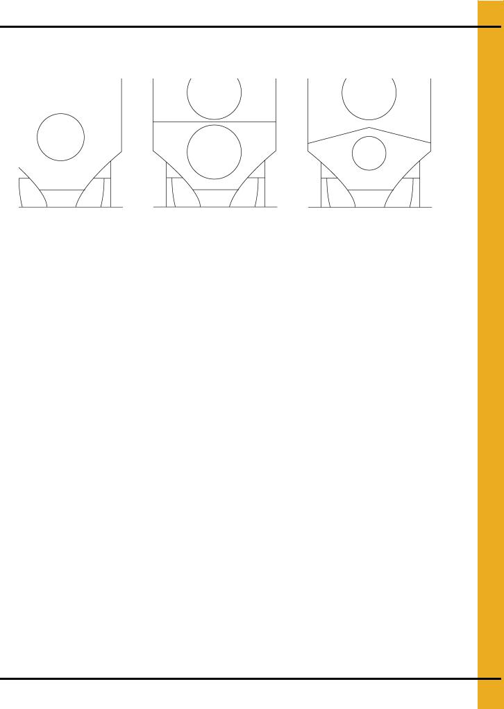
FFI Specifications
|
1 Fan CFAB profile |
|
2 Fan CFAB profile |
|
|
C2100A Profile |
|
||||
|
|
|
|
|
|
|
|
|
|
|
|
|
|
|
|
Figure 4C |
|
|
|
|
|
|
|
|
|
1 Fan CFAB Specifications |
|
|
|
|
|||||
|
|
|
|
|
|
|
|
|
|
|
|
|
|
CFAB 150 |
CFAB 190 |
CFAB 270 |
CFAB 320 |
CFAB 370 |
CFAB 400 |
CFAB 460 |
CFAB 511 |
CFAB 601 |
|
|
|
8' |
10' |
12' |
|
14' |
16' |
18' |
20' |
22' |
26' |
|
|
|
|
|
|
|
|
|
|
|
|
|
|
|
|
|
|
|
|
|
|
|
|
Total Holding Capacity (Bushels) |
173 |
216 |
294 |
|
357 |
436 |
509 |
565 |
622 |
735 |
|
|
|
|
|
|
|
|
|
|
|
|
|
Grain Column Holding Capacity (Bushels) |
149 |
186 |
257 |
|
300 |
376 |
414 |
460 |
506 |
598 |
|
|
|
|
|
|
|
|
|
|
|
|
|
Fans |
28" |
28" |
36" |
|
40" |
40" |
42" |
42" |
42" |
42" |
|
10-13 HP |
10-13 HP |
15 HP |
|
15 HP |
15 HP |
20 HP |
25 HP |
30 HP |
40 HP |
||
|
|
|
|||||||||
|
|
|
|
|
|
|
|
|
|
|
|
Top Auger |
8" Dia. |
8" Dia. |
8" Dia. |
|
8" Dia. |
8" Dia. |
8" Dia. |
8" Dia. |
8" Dia. |
8" Dia. |
|
1.5 HP |
2 HP |
2 HP |
|
5 HP |
5 HP |
5 HP |
7.5 HP |
7.5 HP |
10 HP |
||
|
|
|
|||||||||
|
|
|
|
|
|
|
|
|
|
|
|
Capacity (BPH) |
680 |
925 |
1150 |
|
1800 |
2800 |
2800 |
2800 |
2800 |
2800 |
|
|
|
|
|
|
|
|
|
|
|
|
|
Bottom Auger |
8" Dia. |
8" Dia. |
8" Dia. |
|
8" Dia. |
8" Dia. |
8" Dia. |
8" Dia. |
8" Dia. |
8" Dia. |
|
1 HP |
1.5 HP |
2 HP |
|
3 HP |
3 HP |
3 HP |
5 HP |
5 HP |
7.5 HP |
||
|
|
|
|||||||||
|
|
|
|
|
|
|
|
|
|
|
|
Meter Roll Drive |
SCR, |
SCR, |
SCR, |
|
SCR, |
SCR, |
SCR, |
SCR, |
SCR, |
SCR, |
|
3/4 HP |
3/4 HP |
3/4 HP |
|
3/4 HP |
3/4 HP |
3/4 HP |
3/4 HP |
3/4 HP |
3/4 HP |
||
|
|
|
|||||||||
|
|
|
|
|
|
|
|
|
|
|
|
Capacity - Maximum Rate1 (BPH) |
1120 |
1400 |
1680 |
|
1960 |
2240 |
2520 |
2800 |
3080 |
3640 |
|
Electrical Load (Fans, Top and Bottom Augers2) |
|
|
|
|
|
|
|
|
|
||
380 Volt, 50 Hz, 3 Phase |
23 |
30 |
30 |
|
32 |
40 |
46 |
61 |
69 |
91 |
|
|
|
|
|
|
|
|
|
|
|
|
|
1Actual discharge rate is controlled by meter roll speed adjustment, at 5% to 100% of maximum rate.
2Excludes auxiliary load and unload conveyor equipment.
PNEG-1717 CE Approved GSI/FFI Portable Dryer Manual |
15 |

4. Specifications
2 Fan CFAB Specifications
|
|
CFAB 510 |
CFAB 600 |
|
|
22' |
26' |
|
|
|
|
|
|
|
|
Total Holding Capacity (Bushels) |
|
622 |
735 |
|
|
|
|
Grain Column Holding Capacity (Bushels) |
|
506 |
598 |
|
|
|
|
Fans |
|
36" 15 HP (2) |
40" 20 HP (2) |
|
|
|
|
Top Auger |
|
8" Dia. 7.5 HP |
8" Dia. 10 HP |
|
|
|
|
Capacity (BPH) |
|
2800 |
2800 |
|
|
|
|
Bottom Auger |
|
8" Dia. 5 HP |
8" Dia. 7.5 HP |
|
|
|
|
Meter Roll Drive |
|
SCR, 3/4 HP |
SCR, 3/4 HP |
|
|
|
|
Capacity - Maximum Rate1 (BPH) |
|
3080 |
3640 |
Electrical Load (Fans, Top and Bottom Augers2) |
|
|
|
380 Volt, 50 Hz, 3 Phase |
|
69 |
109 |
|
|
|
|
1Actual discharge rate is controlled by meter roll speed adjustment, at 5% to 100% of maximum rate.
2Excludes auxiliary load and unload conveyor equipment.
C2100A Specifications
|
|
C2120A |
C2122A |
C2125A |
C2130A |
C2132A |
C2140A |
|
|
14' |
16' |
18' |
20' |
22' |
26' |
|
|
|
|
|
|
|
|
|
|
|
|
|
|
|
|
Total Holding Capacity (Bushels) |
|
375 |
436 |
490 |
544 |
599 |
708 |
|
|
|
|
|
|
|
|
Grain Column Holding Capacity (Bushels) |
|
322 |
376 |
415 |
460 |
517 |
600 |
|
|
|
|
|
|
|
|
Fans |
|
28" 10-13 HP/ |
28" 10-13 HP/ |
28" 10-13 HP/ |
28" 10-13 HP/ |
28" 10-13 HP/ |
28" 10-13 HP/ |
|
28" 10-13 HP |
36" 15 HP |
36" 15 HP |
40" 20 HP |
42" 20 HP |
42" 25 HP |
|
|
|
||||||
|
|
|
|
|
|
|
|
Top Auger |
|
8" Dia. 5 HP |
8" Dia. 5 HP |
8" Dia. 5 HP |
8" Dia. 7.5 HP |
8" Dia. 7.5 HP |
8" Dia. 10 HP |
|
|
|
|
|
|
|
|
Capacity (BPH) |
|
1800 |
2800 |
2800 |
2800 |
2800 |
2800 |
|
|
|
|
|
|
|
|
Bottom Auger |
|
8" Dia. 3 HP |
8" Dia. 3 HP |
8" Dia. 3 HP |
8" Dia. 5 HP |
8" Dia. 5 HP |
8" Dia. 7.5 HP |
|
|
|
|
|
|
|
|
Meter Roll Drive |
|
SCR, 3/4 HP |
SCR, 3/4 HP |
SCR, 3/4 HP |
SCR, 3/4 HP |
SCR, 3/4 HP |
SCR, 3/4 HP |
|
|
|
|
|
|
|
|
Capacity - Maximum Rate1 (BPH) |
|
1960 |
2240 |
2520 |
2800 |
3080 |
3640 |
Electrical Load (Fans, Top and Bottom Augers2) |
|
|
|
|
|
|
|
380 Volt, 50 Hz, 3 Phase |
|
50 |
56 |
56 |
63 |
69 |
87 |
|
|
|
|
|
|
|
|
1Actual discharge rate is controlled by meter roll speed adjustment, at 5% to 100% of maximum rate.
2Excludes auxiliary load and unload conveyor equipment.
16 |
PNEG-1717 CE Approved GSI/FFI Portable Dryer Manual |
4. Specifications
GSI Dimensions
Figure 4D
Figure 4E
PNEG-1717 CE Approved GSI/FFI Portable Dryer Manual |
17 |
|
|
4. Specifications |
|
|
|
|
|
|
|
|
|
|
||
|
|
|
|
|
|
|
|
|
|
|
|
|
||
|
|
|
|
Single Module GSI Transport and Installation Dimensions |
|
|
||||||||
|
|
|
|
|
Values are Valid for Transportation of Stack Modules |
|
|
|||||||
|
|
|
|
|
|
|
|
|
|
|
|
|
|
|
|
|
|
|
A |
B |
|
C |
|
D |
E |
F |
G |
H |
|
|
|
|
|
|
|
|
|
|
|
|
|
|
||
|
|
|
Dryer |
Transport |
Installed |
|
Installed Height |
Height w/o |
Frame |
Transport |
Installed |
Transport |
||
|
|
|
Basket |
|
|
|
|
|||||||
|
|
|
|
Wet |
|
Standard |
||||||||
|
|
|
|
Height |
Width |
|
|
Wet Bin |
Width |
Width |
Length |
Length |
||
|
|
|
|
|
|
|
Bin |
|
Top |
|
|
|
|
|
|
|
|
|
|
|
|
|
|
|
|
|
|
|
|
|
|
|
1108T |
4089.4 |
2438.4 |
|
4419.6 |
|
3962.4 |
3581.4 |
1955.8 |
2438.4 |
4622.8 |
5232.4 |
|
|
|
(13' 5'') |
(8') |
|
(14' 6'') |
|
(13') |
(11' 9'') |
(6' 5'') |
(8') |
(15' 2'') |
(17' 2'') |
|
|
|
|
|
|
|
|||||||||
|
|
|
1112 |
4089.4 |
2438.4 |
|
4419.6 |
|
3962.4 |
3581.4 |
1955.8 |
2438.4 |
5842.0 |
6451.6 |
|
|
|
(13' 5'') |
(8') |
|
(14' 6'') |
|
(13') |
(11' 9'') |
(6' 5'') |
(8') |
(19' 2'') |
(21' 2'') |
|
|
|
|
|
|
|
|||||||||
|
|
|
|
|
|
|
|
|
|
|
|
|
|
|
|
|
|
1114 |
4089.4 |
2438.4 |
|
4419.6 |
|
3962.4 |
3581.4 |
1955.8 |
2438.4 |
6451.6 |
7061.2 |
|
|
|
(13' 5'') |
(8') |
|
(14' 6'') |
|
(13') |
(11' 9'') |
(6' 5'') |
(8') |
(21' 2'') |
(23' 2'') |
|
|
|
|
|
|
|
|||||||||
|
|
|
1116 |
4089.4 |
2438.4 |
|
4419.6 |
|
3962.4 |
3581.4 |
1955.8 |
2438.4 |
7061.2 |
7670.8 |
|
|
|
(13' 5'') |
(8') |
|
(14' 6'') |
|
(13') |
(11' 9'') |
(6' 5'') |
(8') |
(23' 2'') |
(25' 2'') |
|
|
|
|
|
|
|
|||||||||
|
|
|
|
|
|
|
|
|
|
|
|
|
|
|
|
|
|
1118 |
4089.4 |
2438.4 |
|
4419.6 |
|
3962.4 |
3581.4 |
1955.8 |
2438.4 |
7670.8 |
8280.4 |
|
|
|
(13' 5'') |
(8') |
|
(14' 6'') |
|
(13') |
(11' 9'') |
(6' 5'') |
(8') |
(25' 2'') |
(27' 2'') |
|
|
|
|
|
|
|
|||||||||
|
|
|
1120 |
4089.4 |
2438.4 |
|
4419.6 |
|
3962.4 |
3581.4 |
1955.8 |
2438.4 |
8280.4 |
8890.0 |
|
|
|
(13' 5'') |
(8') |
|
(14' 6'') |
|
(13') |
(11' 9'') |
(6' 5'') |
(8') |
(27' 2'') |
(29' 2'') |
|
|
|
|
|
|
|
|||||||||
|
|
|
|
|
|
|
|
|
|
|
|
|
|
|
|
|
|
1122 |
4089.4 |
2438.4 |
|
4419.6 |
|
3962.4 |
3581.4 |
1955.8 |
2438.4 |
8890.0 |
9499.6 |
|
|
|
(13' 5'') |
(8') |
|
(14' 6'') |
|
(13') |
(11' 9'') |
(6' 5'') |
(8') |
(29' 2'') |
(31' 2'') |
|
|
|
|
|
|
|
|||||||||
|
|
|
1126 |
4089.4 |
2438.4 |
|
4419.6 |
|
3962.4 |
3581.4 |
1955.8 |
2438.4 |
10109.2 |
10718.8 |
|
|
|
(13' 5'') |
(8') |
|
(14' 6'') |
|
(13') |
(11' 9'') |
(6' 5'') |
(8') |
(33' 2'') |
(35' 2'') |
|
|
|
|
|
|
|
|||||||||
|
|
|
|
|
|
|
|
|
|
|
|
|
|
|
|
|
|
1214 |
4089.4 |
2438.4 |
|
4419.6 |
|
3962.4 |
3581.4 |
1955.8 |
2438.4 |
6451.6 |
7061.2 |
|
|
|
(13' 5'') |
(8') |
|
(14' 6'') |
|
(13') |
(11' 9'') |
(6' 5'') |
(8') |
(21' 2'') |
(23' 2'') |
|
|
|
|
|
|
|
|||||||||
|
|
|
1216 |
4089.4 |
2438.4 |
|
4419.6 |
|
3962.4 |
3581.4 |
1955.8 |
2438.4 |
7061.2 |
7670.8 |
|
|
|
(13' 5'') |
(8') |
|
(14' 6'') |
|
(13') |
(11' 9'') |
(6' 5'') |
(8') |
(23' 2'') |
(25' 2'') |
|
|
|
|
|
|
|
|||||||||
|
|
|
|
|
|
|
|
|
|
|
|
|
|
|
|
|
|
1218 |
4089.4 |
2438.4 |
|
4419.6 |
|
3962.4 |
3581.4 |
1955.8 |
2438.4 |
7670.8 |
8280.4 |
|
|
|
(13' 5'') |
(8') |
|
(14' 6'') |
|
(13') |
(11' 9'') |
(6' 5'') |
(8') |
(25' 2'') |
(27' 2'') |
|
|
|
|
|
|
|
|||||||||
|
|
|
1220 |
4089.4 |
2438.4 |
|
4419.6 |
|
3962.4 |
3581.4 |
1955.8 |
2438.4 |
8280.4 |
8890.0 |
|
|
|
(13' 5'') |
(8') |
|
(14' 6'') |
|
(13') |
(11' 9'') |
(6' 5'') |
(8') |
(27' 2'') |
(29' 2'') |
|
|
|
|
|
|
|
|||||||||
|
|
|
|
|
|
|
|
|
|
|
|
|
|
|
|
|
|
1222 |
4089.4 |
2438.4 |
|
4419.6 |
|
3962.4 |
3581.4 |
1955.8 |
2438.4 |
8890.0 |
9499.6 |
|
|
|
(13' 5'') |
(8') |
|
(14' 6'') |
|
(13') |
(11' 9'') |
(6' 5'') |
(8') |
(29' 2'') |
(31' 2'') |
|
|
|
|
|
|
|
|||||||||
|
|
|
1226 |
4089.4 |
2438.4 |
|
4419.6 |
|
3962.4 |
3581.4 |
1955.8 |
2438.4 |
10109.2 |
10718.8 |
|
|
|
(13' 5'') |
(8') |
|
(14' 6'') |
|
(13') |
(11' 9'') |
(6' 5'') |
(8') |
(33' 2'') |
(35' 2'') |
|
|
|
|
|
|
|
|||||||||
|
|
|
|
|
|
|
|
|
|
|
|
|
|
|
|
|
|
1214S |
4089.4 |
2641.6 |
|
4419.6 |
|
3962.4 |
3581.4 |
1955.8 |
2438.4 |
6451.6 |
7061.2 |
|
|
|
(13' 5'') |
(8' 8'') |
|
(14' 6'') |
|
(13') |
(11' 9'') |
(6' 5'') |
(8') |
(21' 2'') |
(23' 2'') |
|
|
|
|
|
|
|
|||||||||
|
|
|
1218S |
4089.4 |
2641.6 |
|
4419.6 |
|
3962.4 |
3581.4 |
1955.8 |
2438.4 |
7670.8 |
8280.4 |
|
|
|
(13' 5'') |
(8' 8'') |
|
(14' 6'') |
|
(13') |
(11' 9'') |
(6' 5'') |
(8') |
(25' 2'') |
(27' 2'') |
|
|
|
|
|
|
|
|||||||||
|
|
|
|
|
|
|
|
|
|
|
|
|
|
|
|
|
|
1220S |
4089.4 |
2641.6 |
|
4419.6 |
|
3962.4 |
3581.4 |
1955.8 |
2438.4 |
8280.4 |
8890.0 |
|
|
|
(13' 5'') |
(8' 8'') |
|
(14' 6'') |
|
(13') |
(11' 9'') |
(6' 5'') |
(8') |
(27' 2'') |
(29' 2'') |
|
|
|
|
|
|
|
|||||||||
|
|
|
1222S |
4089.4 |
2641.6 |
|
4419.6 |
|
3962.4 |
3581.4 |
1955.8 |
2438.4 |
8890.0 |
9499.6 |
|
|
|
(13' 5'') |
(8' 8'') |
|
(14' 6'') |
|
(13') |
(11' 9'') |
(6' 5'') |
(8') |
(29' 2'') |
(31' 2'') |
|
|
|
|
|
|
|
|||||||||
|
|
|
|
|
|
|
|
|
|
|
|
|
|
|
|
|
|
1226S |
4089.4 |
2641.6 |
|
4419.6 |
|
3962.4 |
3581.4 |
1955.8 |
2438.4 |
10109.2 |
10718.8 |
|
|
|
(13' 5'') |
(8' 8'') |
|
(14' 6'') |
|
(13') |
(11' 9'') |
(6' 5'') |
(8') |
(33' 2'') |
(35' 2'') |
|
|
|
|
|
|
|
|||||||||
|
|
|
|
|
|
|
|
|
|
|
|
|
|
|
|
|
NOTE: All dimensions are in mm. |
|
|
|
|
|
|
|
|
||||
|
|
|
|
|
|
|
|
|
|
|
|
|
|
|
18 |
|
|
|
|
|
|
|
PNEG-1717 CE Approved GSI/FFI Portable Dryer Manual |
||||||
|
|
|
|
|
|
|
|
|
|
|
|
|
|
|
4. Specifications
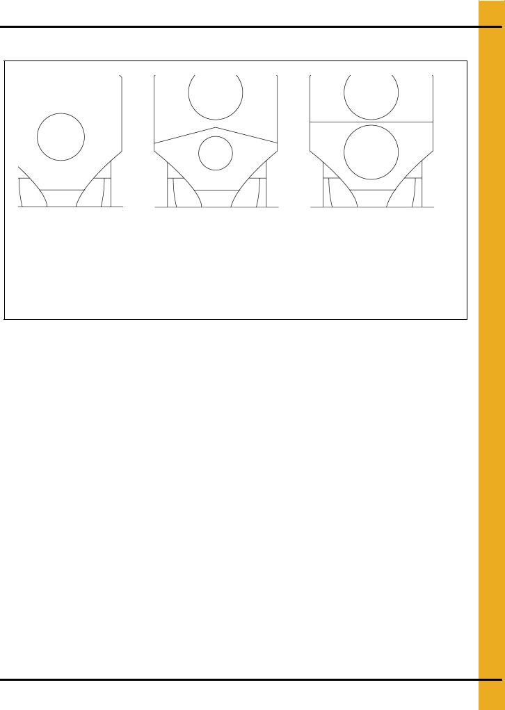
GSI Specifications
1100 Series profile 1200 Series profile 1200S Series profile
Figure 4F
1100 Series Dryer Specifications
|
1108T |
1112 |
1114 |
1116 |
1118 |
1120 |
1122 |
1126 |
|
|
|
|
|
|
|
|
|
|
|
|
|
|
|
|
|
|
|
|
|
Total Holding Capacity (Bushels) |
190 |
327 |
381 |
436 |
490 |
544 |
599 |
708 |
|
|
|
|
|
|
|
|
|
|
|
Grain Column Holding Capacity (Bushels) |
160 |
282 |
329 |
376 |
423 |
470 |
517 |
611 |
|
|
|
|
|
|
|
|
|
|
|
Fans |
28'' |
36'' |
40'' |
40'' |
42'' |
42'' |
42'' |
42'' |
|
10-13 HP |
15 HP |
15 HP |
15 HP |
20 HP |
25 HP |
30 HP |
40 HP |
||
|
|||||||||
|
|
|
|
|
|
|
|
|
|
Top Auger |
8'' Dia. |
8'' Dia. |
8'' Dia. |
8'' Dia. |
8'' Dia. |
8'' Dia. |
8'' Dia. |
8'' Dia. |
|
1-1/2 HP |
3 HP |
5 HP |
5 HP |
5 HP |
7-1/2 HP |
7-1/2 HP |
10 HP |
||
|
|||||||||
|
|
|
|
|
|
|
|
|
|
Capacity (BPH) |
2900 |
2900 |
3800 |
3800 |
3800 |
3800 |
3800 |
3800 |
|
|
|
|
|
|
|
|
|
|
|
Bottom Auger |
8'' Dia. |
8'' Dia. |
8'' Dia. |
8'' Dia. |
8'' Dia. |
8'' Dia. |
8'' Dia. |
8'' Dia. |
|
1 HP |
1-1/2 HP |
3 HP |
5 HP |
5 HP |
7-1/2 HP |
7-1/2 HP |
10 HP |
||
|
|||||||||
|
|
|
|
|
|
|
|
|
|
Meter Roll Drive |
SCR, |
SCR, |
SCR, |
SCR, |
SCR, |
SCR, |
SCR, |
SCR, |
|
3/4 HP |
3/4 HP |
3/4 HP |
3/4 HP |
3/4 HP |
3/4 HP |
3/4 HP |
3/4 HP |
||
|
|||||||||
|
|
|
|
|
|
|
|
|
|
Capacity - Maximum Rate1 (BPH) |
1120 |
1680 |
1960 |
2240 |
2520 |
2800 |
3080 |
3640 |
|
Electrical Load (Fans, Top and Bottom Augers2) |
|
|
|
|
|
|
|
|
|
3 Phase, 380 Volt |
22 |
33 |
36 |
44 |
49 |
68 |
75 |
88 |
|
|
|
|
|
|
|
|
|
|
1Actual discharge rate is controlled by meter roll speed adjustment, at 5% to 100% of maximum rate.
2Excludes auxiliary load and unload conveyor equipment.
PNEG-1717 CE Approved GSI/FFI Portable Dryer Manual |
19 |

4. Specifications
1200 Series Dryer Specifications
|
1214 |
1216 |
1218 |
1220 |
1222 |
1226 |
|
|
|
|
|
|
|
|
|
|
|
|
|
|
|
|
|
Total Holding Capacity (Bushels) |
381 |
436 |
490 |
544 |
599 |
708 |
|
|
|
|
|
|
|
|
|
Grain Column Holding |
329 |
376 |
423 |
470 |
517 |
611 |
|
Capacity (Bushels) |
|||||||
|
|
|
|
|
|
||
|
|
|
|
|
|
|
|
Fans |
26'' 10-13 HP |
26'' 10-13 HP |
26'' 10-13 HP |
28'' 10-13 HP |
28'' 10-13 HP |
28'' 10-13 HP |
|
36'' 10-13 HP |
36'' 15 HP |
36'' 15 HP |
40" 15 HP |
42'' 20 HP |
42'' 25 HP |
||
|
|||||||
|
|
|
|
|
|
|
|
Top Auger |
8'' Dia. |
8'' Dia. |
8'' Dia. |
8'' Dia. |
8'' Dia. |
8'' Dia. |
|
5 HP |
5 HP |
5 HP |
7-1/2 HP |
7-1/2 HP |
10 HP |
||
|
|||||||
|
|
|
|
|
|
|
|
Capacity (BPH) |
3800 |
3800 |
3800 |
3800 |
3800 |
3800 |
|
|
|
|
|
|
|
|
|
Bottom Auger |
8'' Dia. |
8'' Dia. |
8'' Dia. |
8'' Dia. |
8'' Dia. |
8'' Dia. |
|
5 HP |
5 HP |
5 HP |
7-1/2 HP |
7-1/2 HP |
10 HP |
||
|
|||||||
|
|
|
|
|
|
|
|
Meter Roll Drive |
SCR, 3/4 HP |
SCR, 3/4 HP |
SCR, 3/4 HP |
SCR, 3/4 HP |
SCR, 3/4 HP |
SCR, 3/4 HP |
|
|
|
|
|
|
|
|
|
Capacity - Maximum Rate1 (BPH) |
1960 |
2240 |
2520 |
2800 |
3080 |
3640 |
|
Electrical Load (Fans, Top and Bottom Augers2) |
|
|
|
|
|
||
3 Phase, 380 Volt |
50 |
61 |
61 |
70 |
75 |
90 |
|
|
|
|
|
|
|
|
|
1Actual discharge rate is controlled by meter roll speed adjustment, at 5% to 100% of maximum rate.
2Excludes auxiliary load and unload conveyor equipment.
1200S Series Dryer Specifications
|
1214S |
1218S |
1220S |
1222S |
1226S |
|
|
|
|
|
|
|
|
|
|
|
|
|
|
|
Total Holding Capacity (Bushels) |
381 |
490 |
544 |
599 |
708 |
|
|
|
|
|
|
|
|
Grain Column Holding Capacity (Bushels) |
329 |
423 |
470 |
517 |
611 |
|
|
|
|
|
|
|
|
Fans |
28'' 10-13 HP (2) |
36'' 10-13 HP (2) |
36'' 15 HP (2) |
36'' 15 HP (2) |
40'' 25 HP (2) |
|
|
|
|
|
|
|
|
Top Auger |
8'' Dia. |
8'' Dia. |
8'' Dia. |
8'' Dia. |
8'' Dia. |
|
5 HP |
5 HP |
7-1/2 HP |
7-1/2 HP |
10 HP |
||
|
||||||
|
|
|
|
|
|
|
Capacity (BPH) |
3800 |
3800 |
3800 |
3800 |
3800 |
|
|
|
|
|
|
|
|
Bottom Auger |
8'' Dia. |
8'' Dia. |
8'' Dia. |
8'' Dia. |
8'' Dia. |
|
5 HP |
5 HP |
7-1/2 HP |
7-1/2 HP |
10 HP |
||
|
||||||
|
|
|
|
|
|
|
Meter Roll Drive |
SCR, 3/4 HP |
SCR, 3/4 HP |
SCR, 3/4 HP |
SCR, 3/4 HP |
SCR, 3/4 HP |
|
|
|
|
|
|
|
|
Capacity - Maximum Rate1 (BPH) |
1960 |
2520 |
2800 |
3080 |
3640 |
|
Electrical Load (Fans, Top and Bottom Augers2) |
|
|
|
|
||
3 Phase, 380 Volt |
50 |
50 |
80 |
80 |
115 |
|
|
|
|
|
|
|
|
1Actual discharge rate is controlled by meter roll speed adjustment, at 5% to 100% of maximum rate.
2Excludes auxiliary load and unload conveyor equipment.
20 |
PNEG-1717 CE Approved GSI/FFI Portable Dryer Manual |

4. Specifications
All Stack Dimensions
|
|
NOTE: All dimensions are in mm. |
|
|
|
|
|
|
Figure 4G Example of Stack Dryer Footprint |
|
|
|
|
|
|
PNEG-1717 CE Approved GSI/FFI Portable Dryer Manual |
21 |
||
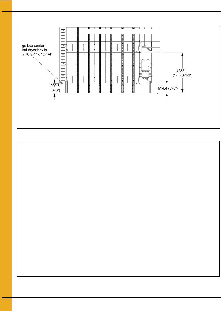
4. Specifications
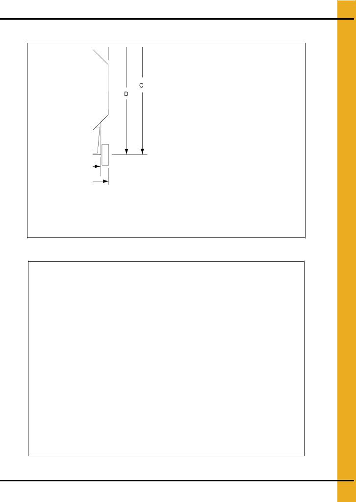
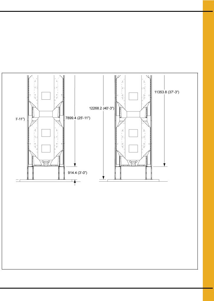
All Stack Dimensions (Continued)
“X” - Varies with dryer length (See Chart on Page 23.)
Figure 4H Side View - 2 Module Stack Dryer
“X” - Varies with dryer length
(See Chart on Page 23.)
Figure 4I Stack Dryer Dimension (Side View - 3 Module Stack Dryer)
NOTE: All dimensions are in mm.
22 |
PNEG-1717 CE Approved GSI/FFI Portable Dryer Manual |
4. Specifications
All Stack Dimensions (Continued)
Dryer Installed Length (1, 2 and 3 Module Stacks)
Basket Length |
Installed Length |
|
|
14 |
7264.4 (23' 10") |
18 |
8483.6 (27' 10") |
|
|
20 |
9093.2 (29' 10") |
22 |
9702.8 (31' 10") |
|
|
26 |
10922.0 (35' 10") |
|
|
End View - 2 Module Stack Dryer |
End View - 3 Module Stack Dryer |
Figure 4J
NOTE: All dimensions are in mm.
PNEG-1717 CE Approved GSI/FFI Portable Dryer Manual |
23 |

4. Specifications
All Stack Specifications
|
|
14' |
18' |
20' |
22' |
26' |
|
|
|
|
|
|
|
|
Total Holding Capacity (Bushels) |
731 |
940 |
1044 |
1149 |
1304 |
|
Grain Column Holding Capacity (Bushels) |
679 |
873 |
970 |
1067 |
1261 |
|
|
|
|
|
|
|
|
Fans |
28" 10-13 HP |
36" 10-12 HP |
36" 15 HP |
36" 15 HP |
40" 25 HP |
|
40" 15 HP |
42" 20 HP |
42" 25 HP |
42" 30 HP |
42" 40 HP |
|
|
|
|||||
|
Top Auger |
8" Dia. 5 HP |
8" Dia. 5 HP |
8" Dia. 7.5 HP |
8" Dia. 7.5 HP |
8" Dia. 10 HP |
|
|
|
|
|
|
|
|
Capacity (BPH) |
3800 |
3800 |
3800 |
3800 |
3800 |
|
Bottom Auger |
8" Dia. 5 HP |
8" Dia. 5 HP |
8" Dia. 7.5 HP |
8" Dia. 7.5 HP |
8" Dia. 10 HP |
|
|
|
|
|
|
|
|
Meter Roll Drive |
SCR, 1/3 HP |
SCR, 1/3 HP |
SCR, 1/3 HP |
SCR, 1/3 HP |
SCR, 1/3 HP |
|
Capacity - Maximum Rate1 (BPH) |
1960 |
2520 |
2800 |
3080 |
3640 |
|
Electrical Load (Fans, Top and Bottom Augers2) |
|
|
|
|
|
|
3 Phase, 380-400 Volt |
61 |
66 |
91 |
96 |
141 |
|
|
|
|
|
|
|
1Actual discharge rate is controlled by meter roll speed adjustment, at 5% to 100% of maximum rate.
2Excludes auxiliary load and unload conveyor equipment.
|
|
14' |
18' |
20' |
22' |
26' |
|
|
|
|
|
|
|
|
Total Holding Capacity (Bushels) |
731 |
940 |
1044 |
1149 |
1304 |
|
Grain Column Holding Capacity (Bushels) |
679 |
873 |
970 |
1067 |
1261 |
|
|
|
|
|
|
|
|
Fans |
28" 10-13 HP |
36" 10-13 HP |
36" 15 HP |
36" 15 HP |
40" 25 HP |
|
28" 10-13 HP |
36" 10-13 HP |
36" 15 HP |
36" 15 HP |
40" 25 HP |
|
|
|
|||||
|
Top Auger |
8" Dia. 5 HP |
8" Dia. 5 HP |
8" Dia. 7.5 HP |
8" Dia. 7.5 HP |
8" Dia. 10 HP |
|
|
|
|
|
|
|
|
Capacity (BPH) |
3800 |
3800 |
3800 |
3800 |
3800 |
|
Bottom Auger |
8" Dia. 5 HP |
8" Dia. 5 HP |
8" Dia. 7.5 HP |
8" Dia. 7.5 HP |
8" Dia. 10 HP |
|
|
|
|
|
|
|
|
Meter Roll Drive |
SCR, 1/3 HP |
SCR, 1/3 HP |
SCR, 1/3 HP |
SCR, 1/3 HP |
SCR, 1/3 HP |
|
Capacity - Maximum Rate1 (BPH) |
1960 |
2520 |
2800 |
3080 |
3640 |
|
Electrical Load (Fans, Top and Bottom Augers2) |
|
|
|
|
|
|
3 Phase, 380-400 Volt |
69 |
69 |
98 |
98 |
154 |
|
|
|
|
|
|
|
1Actual discharge rate is controlled by meter roll speed adjustment, at 5% to 100% of maximum rate.
2Excludes auxiliary load and unload conveyor equipment.
|
|
14' |
18' |
20' |
22' |
26' |
|
|
|
|
|
|
|
|
Total Holding Capacity (Bushels) |
1074 |
1381 |
1534 |
1688 |
1995 |
|
Grain Column Holding Capacity (Bushels) |
1022 |
1314 |
1460 |
1606 |
1898 |
|
|
|
|
|
|
|
|
Fans |
40" 15 HP |
42" 20 HP |
42" 25 HP |
42" 30 HP |
42" 40 HP |
|
40" 15 HP |
42" 20 HP |
42" 25 HP |
42" 30 HP |
42" 40 HP |
|
|
|
|||||
|
Top Auger |
8" Dia. 5 HP |
8" Dia. 5 HP |
8" Dia. 7.5 HP |
8" Dia. 7.5 HP |
8" Dia. 10 HP |
|
|
|
|
|
|
|
|
Capacity (BPH) |
3800 |
3800 |
3800 |
3800 |
3800 |
|
Bottom Auger |
8" Dia. 5 HP |
8" Dia. 5 HP |
8" Dia. 7.5 HP |
8" Dia. 7.5 HP |
8" Dia. 10 HP |
|
|
|
|
|
|
|
|
Meter Roll Drive |
SCR, 1/3 HP |
SCR, 1/3 HP |
SCR, 1/3 HP |
SCR, 1/3 HP |
SCR, 1/3 HP |
|
Capacity - Maximum Rate1 (BPH) |
1960 |
2520 |
2800 |
3080 |
3640 |
|
Electrical Load (Fans, Top and Bottom Augers2) |
|
|
|
|
|
|
3 Phase, 380-400 Volt |
72 |
88 |
116 |
131 |
179 |
|
|
|
|
|
|
|
1Actual discharge rate is controlled by meter roll speed adjustment, at 5% to 100% of maximum rate.
2Excludes auxiliary load and unload conveyor equipment.
24 |
PNEG-1717 CE Approved GSI/FFI Portable Dryer Manual |
4. Specifications
All Stack Specifications (Continued)
|
|
14' |
18' |
20' |
22' |
26' |
|
|
|
|
|
|
|
|
|
|
|
|
|
|
|
Total Holding Capacity (Bushels) |
1074 |
1381 |
1534 |
1688 |
1995 |
|
|
|
|
|
|
|
|
Grain Column Holding Capacity (Bushels) |
1022 |
1314 |
1460 |
1606 |
1898 |
|
|
|
|
|
|
|
|
Fans |
28" 10-13 HP |
36" 10-13 HP |
36" 15 HP |
36" 15 HP |
40" 25 HP |
|
40" 15 HP |
42" 20 HP |
42" 25 HP |
42" 30 HP |
42" 40 HP |
|
|
|
|||||
|
|
|
|
|
|
|
|
Top Auger |
8" Dia. 5 HP |
8" Dia. 5 HP |
8" Dia. 7.5 HP |
8" Dia. 7.5 HP |
8" Dia. 10 HP |
|
|
|
|
|
|
|
|
Capacity (BPH) |
3800 |
3800 |
3800 |
3800 |
3800 |
|
|
|
|
|
|
|
|
Bottom Auger |
8" Dia. 5 HP |
8" Dia. 5 HP |
8" Dia. 7.5 HP |
8" Dia. 7.5 HP |
8" Dia. 10 HP |
|
|
|
|
|
|
|
|
Meter Roll Drive |
SCR, 1/3 HP |
SCR, 1/3 HP |
SCR, 1/3 HP |
SCR, 1/3 HP |
SCR, 1/3 HP |
|
|
|
|
|
|
|
|
Capacity - Maximum Rate1 (BPH) |
1960 |
2520 |
2800 |
3080 |
3640 |
|
Electrical Load (Fans, Top and Bottom Augers2) |
|
|
|
|
|
|
3 Phase, 380-400 Volt |
80 |
91 |
123 |
133 |
192 |
|
|
|
|
|
|
|
1Actual discharge rate is controlled by meter roll speed adjustment, at 5% to 100% of maximum rate.
2Excludes auxiliary load and unload conveyor equipment.
|
|
14' |
18' |
20' |
22' |
26' |
|
|
|
|
|
|
|
|
|
|
|
|
|
|
|
Total Holding Capacity (Bushels) |
1074 |
1381 |
1534 |
1688 |
1995 |
|
|
|
|
|
|
|
|
Grain Column Holding Capacity (Bushels) |
1022 |
1314 |
1460 |
1606 |
1898 |
|
|
|
|
|
|
|
|
Fans |
28" 10-13 HP |
36" 10-13 HP |
36" 15 HP |
36" 15 HP |
40" 25 HP |
|
|
|
|
|
|
|
|
Top Auger |
8" Dia. 5 HP |
8" Dia. 5 HP |
8" Dia. 7.5 HP |
8" Dia. 7.5 HP |
8" Dia. 10 HP |
|
|
|
|
|
|
|
|
Capacity (BPH) |
3800 |
3800 |
3800 |
3800 |
3800 |
|
|
|
|
|
|
|
|
Bottom Auger |
8" Dia. 5 HP |
8" Dia. 5 HP |
8" Dia. 7.5 HP |
8" Dia. 7.5 HP |
8" Dia. 10 HP |
|
|
|
|
|
|
|
|
Meter Roll Drive |
SCR, 1/3 HP |
SCR, 1/3 HP |
SCR, 1/3 HP |
SCR, 1/3 HP |
SCR, 1/3 HP |
|
|
|
|
|
|
|
|
Capacity - Maximum Rate1 (BPH) |
1960 |
2520 |
2800 |
3080 |
3640 |
|
Electrical Load (Fans, Top and Bottom Augers2) |
|
|
|
|
|
|
3 Phase, 380-400 Volt |
97 |
97 |
137 |
137 |
218 |
|
|
|
|
|
|
|
1Actual discharge rate is controlled by meter roll speed adjustment, at 5% to 100% of maximum rate.
2Excludes auxiliary load and unload conveyor equipment.
PNEG-1717 CE Approved GSI/FFI Portable Dryer Manual |
25 |
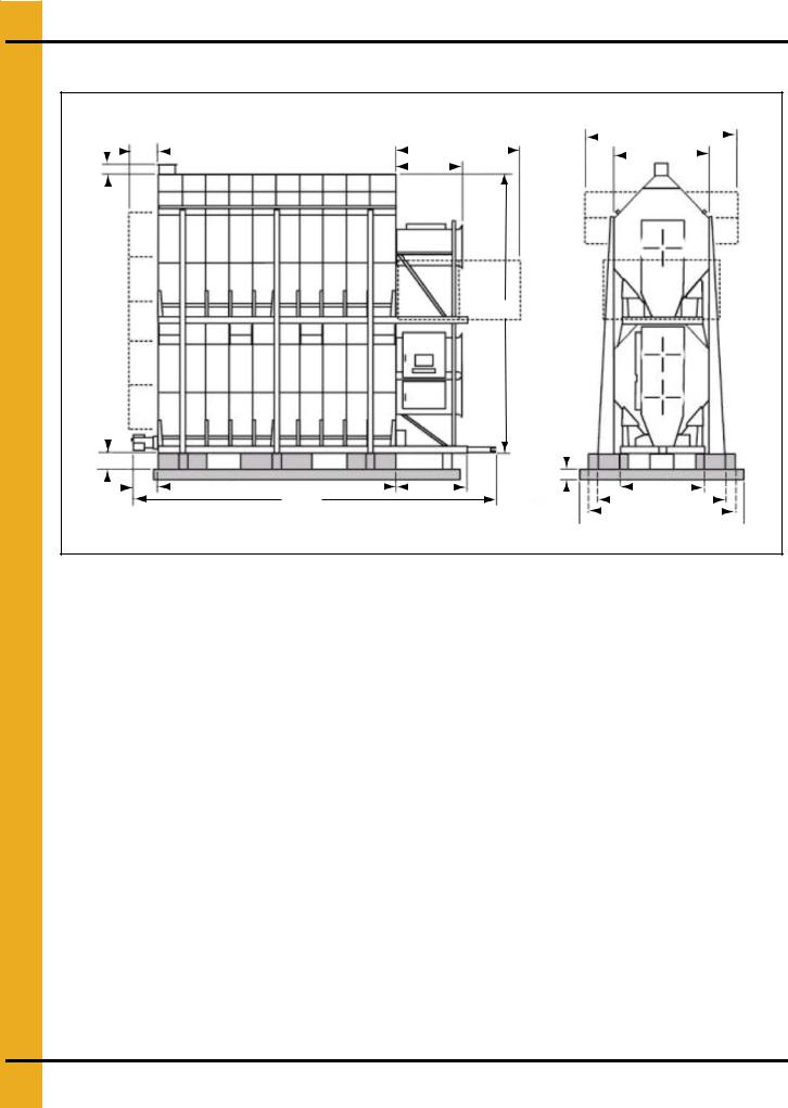
4. Specifications
All Stack Specifications (Continued)
|
|
|
|
|
|
|
|
|
|
|
|
|
|
3962.4 (13'-0")-OPTIONAL |
||||||||
H |
2362.2 (7'-9")-SAFETY |
|
|
|
CATWALK |
|
|
|||||||||||||||
|
|
|
|
|||||||||||||||||||
|
|
|
||||||||||||||||||||
|
|
|
|
|
812.8 (2'-8")-REAR SAFETY CAGE |
|
|
PLATFORM |
|
|
|
|
|
|
J |
|
|
|
|
|||
|
|
|
|
|
SEE NOTE 3 |
|
|
|
G |
|
|
|
|
|
|
|
|
|
|
|
|
|
|
|
|
|
|
|
|
|
|
|
|
|
|
|
|
|
|||||||
|
|
SEE |
|
|
|
NOTE 2 |
|
L |
|||
L |
|||
|
|
|
|
|
|
|
|
|
|
|
|
|
|
|
|
|
|
|
|
|
|
|
|
|
|
|
|
|
|
|
|
|
|
|
|
|
|
|
|
|
|
|
|
|
|
|
|
E |
|
|
|
|
|
|
|
|
|
|
|
|
|
|
|
|
|
|
|
|
|||
|
|
|
|
|
|
|
|
|
|
|
|
|
|
|
|
|
|
|
|
||||
|
|
|
B |
|
C |
|
|
|
D |
|
SEE |
|
|
|
|
|
|
N |
|
|
|
|
|
|
|
|
|
|
|
|
|
|
|
|
|
|
|
|
|
|
|||||||
|
|
|
|
|
|
|
|
|
|
|
|
|
|
|
M |
|
|
|
|||||
|
|
|
|
|
|
A |
|
NOTE 1 |
|
|
|
F |
|
|
|
|
|
|
|||||
|
|
|
|
|
|
|
|
|
|
|
|
|
|
|
|
|
|
|
|||||
|
|
|
|
|
|
|
|
|
|
|
|
|
|
|
|
|
|
||||||
 4267.2 (14'-0")
Figure 4K
|
A |
B |
C |
D |
E1 |
F |
G |
H |
J |
L |
M |
N |
|
|
|
|
|
|
|
|
|
|
|
|
|
|
|
14' |
7048.5 |
660.4 |
4267.2 |
1422.4 |
406.4 |
3403.6 |
1466.85 |
203.2 |
2438.4 |
7251.7 |
3048.0 |
1930.4 |
|
(23'-1-1/2") |
(2'-2") |
(14'-0") |
(4'-8") |
(16" Min.) |
(11'-2") |
(4'-9-3/4") |
(0'-8") |
(8'-0") |
(23'-9-1/2") |
(10'-0") |
(6'-4") |
||
|
|||||||||||||
|
|
|
|
|
|
|
|
|
|
|
|
|
|
18' |
8267.7 |
660.4 |
5486.4 |
1422.4 |
406.4 |
3403.6 |
1466.85 |
203.2 |
2438.4 |
7251.7 |
3048.0 |
1930.4 |
|
(27'-1-1/2") |
(2'-2") |
(18'-0") |
(4'-8") |
(16" Min.) |
(11'-2") |
(4'-9-3/4") |
(0'-8") |
(8'-0") |
(23'-9-1/2") |
(10'-0") |
(6'-4") |
||
|
|||||||||||||
|
|
|
|
|
|
|
|
|
|
|
|
|
|
20' |
8877.3 |
660.4 |
6096.0 |
1422.4 |
406.4 |
3403.6 |
1466.85 |
203.2 |
2438.4 |
7251.7 |
3048.0 |
1930.4 |
|
(29'-1-1/2") |
(2'-2") |
(20'-0") |
(4'-8") |
(16" Min.) |
(11'-2") |
(4'-9-3/4") |
(0'-8") |
(8'-0") |
(23'-9-1/2") |
(10'-0") |
(6'-4") |
||
|
|||||||||||||
|
|
|
|
|
|
|
|
|
|
|
|
|
|
22' |
9486.9 |
660.4 |
6705.6 |
1422.4 |
406.4 |
3403.6 |
1466.85 |
203.2 |
2438.4 |
7251.7 |
3048.0 |
1930.4 |
|
(31'-1-1/2") |
(2'-2") |
(22'-0") |
(4'-8") |
(16" Min.) |
(11'-2") |
(4'-9-3/4") |
(0'-8") |
(8'-0") |
(23'-9-1/2") |
(10'-0") |
(6'-4") |
||
|
|||||||||||||
|
|
|
|
|
|
|
|
|
|
|
|
|
|
26' |
10706.1 |
660.4 |
7924.8 |
1422.4 |
406.4 |
3403.6 |
1466.85 |
203.2 |
2438.4 |
7251.7 |
3048.0 |
1930.4 |
|
(35'-1-1/2") |
(2'-2") |
(26'-0") |
(4'-8") |
(16" Min.) |
(11'-2") |
(4'-9-3/4") |
(0'-8") |
(8'-0") |
(23'-9-1/2") |
(10'-0") |
(6'-4") |
||
|
|||||||||||||
|
|
|
|
|
|
|
|
|
|
|
|
|
NOTE: All dimensions are in mm.
1.A 12" thick reinforced concrete foundation and 16" pedestal (min.) are required. See bulletin FL-02-2 for details. 32" Thick pedestal required for heat reclaimer option. (See bulletin FL-03-2 for details.)
2.Approximate location of standard service platform shown. See bulletin SP-02-2 for details. For information on optional catwalk, see bulletin CATH-01-5.
3.For safety cage information, refer to bulletin SC-01-2.
26 |
PNEG-1717 CE Approved GSI/FFI Portable Dryer Manual |
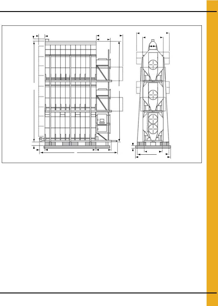
4. Specifications
All Stack Specifications (Continued)
|
|
|
|
|
2362.2 (7'-9")-SAFETY |
3962.4 (13'-0")-OPTIONAL |
||||||||||||||||
H |
|
|
|
CATWALK |
|
|
|
|||||||||||||||
|
812.8 (2'-8")-REAR SAFETY CAGE |
|
PLATFORM |
|
|
|
|
|
|
|||||||||||||
|
|
|
|
|
|
|
|
|
|
|
|
J |
|
|
|
|
||||||
|
|
|
|
|
|
|
|
|
|
|
|
|
|
|
|
|||||||
|
|
|
|
|
SEE NOTE 3 |
|
|
|
G |
|
|
|
|
|
|
|
|
|
|
|
|
|
|
|
|
|
|
|
|
|
|
|
|
|
|
|
|
|
|
|
|
|
|
||
K
L
L
SEE
NOTE 2
E |
|
|
|
|
|
|
|
|
|
|
|
|
|
|
|
|
|
|
|||
|
|
|
|
|
|
|
|
|
|
|
|
|
|
|
|
|
|
||||
|
|
|
B |
|
C |
|
|
|
D |
|
SEE |
|
|
|
|
N |
|
|
|
|
|
|
|
|
|
|
|
|
|
|
|
|
|
|
|
|
|||||||
|
|
|
|
A |
|
|
|
|
|
|
|
|
|
|
|
|
|||||
|
|
|
|
|
|
|
|
|
|
|
|
|
|
F |
|
|
|
|
|||
|
|
|
|
|
|
|
|
|
|
|
NOTE 1 |
|
|
|
|
|
|
|
|
||
|
|
|
|
|
|
|
|
|
|
|
|
|
|
4267.2 (14'-0") |
|
|
|||||
|
|
|
|
|
|
|
|
|
|
|
|
|
|
|
|||||||
Figure 4L
|
A |
B |
C |
D |
E1 |
F |
G |
H |
J |
K |
L |
N |
|
|
|
|
|
|
|
|
|
|
|
|
|
|
|
14' |
7048.5 |
660.4 |
4267.2 |
1422.4 |
406.4 |
3403.6 |
1466.85 |
203.2 |
2438.4 |
914.4 |
7251.7 |
1930.4 |
|
(23'-1-1/2") |
(2'-2") |
(14'-0") |
(4'-8") |
(16" Min.) |
(11'-2") |
(4'-9-3/4") |
(0'-8") |
(8'-0") |
(3'-0") |
(23'-9-1/2") |
(6'-4") |
||
|
|||||||||||||
|
|
|
|
|
|
|
|
|
|
|
|
|
|
18' |
8267.7 |
660.4 |
5486.4 |
1422.4 |
406.4 |
3403.6 |
1466.85 |
203.2 |
2438.4 |
914.4 |
7251.7 |
1930.4 |
|
(27'-1-1/2") |
(2'-2") |
(18'-0") |
(4'-8") |
(16" Min.) |
(11'-2") |
(4'-9-3/4") |
(0'-8") |
(8'-0") |
(3'-0") |
(23'-9-1/2") |
(6'-4") |
||
|
|||||||||||||
|
|
|
|
|
|
|
|
|
|
|
|
|
|
20' |
8877.3 |
660.4 |
6096.0 |
1422.4 |
406.4 |
3403.6 |
1466.85 |
203.2 |
2438.4 |
914.4 |
7251.7 |
1930.4 |
|
(29'-1-1/2") |
(2'-2") |
(20'-0") |
(4'-8") |
(16" Min.) |
(11'-2") |
(4'-9-3/4") |
(0'-8") |
(8'-0") |
(3'-0") |
(23'-9-1/2") |
(6'-4") |
||
|
|||||||||||||
|
|
|
|
|
|
|
|
|
|
|
|
|
|
22' |
9486.9 |
660.4 |
6705.6 |
1422.4 |
406.4 |
3403.6 |
1466.85 |
203.2 |
2438.4 |
914.4 |
7251.7 |
1930.4 |
|
(31'-1-1/2") |
(2'-2") |
(22'-0") |
(4'-8") |
(16" Min.) |
(11'-2") |
(4'-9-3/4") |
(0'-8") |
(8'-0") |
(3'-0") |
(23'-9-1/2") |
(6'-4") |
||
|
|||||||||||||
|
|
|
|
|
|
|
|
|
|
|
|
|
|
26' |
10706.1 |
660.4 |
7924.8 |
1422.4 |
406.4 |
3403.6 |
1466.85 |
203.2 |
2438.4 |
914.4 |
7251.7 |
1930.4 |
|
(35'-1-1/2") |
(2'-2") |
(26'-0") |
(4'-8") |
(16" Min.) |
(11'-2") |
(4'-9-3/4") |
(0'-8") |
(8'-0") |
(3'-0") |
(23'-9-1/2") |
(6'-4") |
||
|
|||||||||||||
|
|
|
|
|
|
|
|
|
|
|
|
|
NOTE: All dimensions are in mm.
1.A 12" thick reinforced concrete foundation and 16" pedestal (min.) are required. See bulletin FL-02-2 for details. 32" Thick pedestal required for heat reclaimer option. (See bulletin FL-03-2 for details.)
2.Approximate location of standard service platform shown. See bulletin SP-02-2 for details. For information on optional catwalk, see bulletin CATH-01-5.
3.For safety cage information, refer to bulletin SC-01-2.
PNEG-1717 CE Approved GSI/FFI Portable Dryer Manual |
27 |
Loading...