


 Loading...
Vision Hybrid for Portable Dryers
Operation Manual
PNEG-1935
Date: 06-04-13
PNEG-1935
|
|
|
|
|
|
2 |
PNEG-1935 Vision Hybrid for Portable Dryers |
|
|
|
|

|
Table of Contents |
Contents |
|
Chapter 1 Safety ..................................................................................................................................................... |
5 |
Safety Guidelines .................................................................................................................................. |
5 |
Dryer Operation ..................................................................................................................................... |
6 |
Emergency Stop Switch ........................................................................................................................ |
6 |
Safety Precautions ................................................................................................................................ |
7 |
Chapter 2 Decals .................................................................................................................................................... |
9 |
Chapter 3 Vision Control Panel .......................................................................................................................... |
13 |
Control Power Switch .......................................................................................................................... |
13 |
Stop Button ......................................................................................................................................... |
13 |
Outside Light Switch ........................................................................................................................... |
14 |
Start Button ......................................................................................................................................... |
14 |
Unload Switch ..................................................................................................................................... |
14 |
Meter Roll Adjustment ......................................................................................................................... |
14 |
Load Switch ......................................................................................................................................... |
15 |
Fan Switch .......................................................................................................................................... |
15 |
Heater Switch ...................................................................................................................................... |
15 |
Chapter 4 Boot Screen ........................................................................................................................................ |
16 |
Boot Screen Description and Button Explanations ............................................................................. |
16 |
Software Update Procedure ................................................................................................................ |
17 |
Chapter 5 Operations .......................................................................................................................................... |
21 |
Default Operation Screen .................................................................................................................... |
21 |
Timers Button ...................................................................................................................................... |
22 |
Load Delay ..................................................................................................................................... |
22 |
Out Of Grain (OOG) Timer ............................................................................................................. |
22 |
Fan Delay ....................................................................................................................................... |
22 |
Unload Delay .................................................................................................................................. |
22 |
Cool Down ...................................................................................................................................... |
22 |
Temp Button ........................................................................................................................................ |
23 |
Plenum Temperature Setpoint......................................................................................................... |
24 |
Grain Temperature Setpoint ............................................................................................................ |
24 |
Setup Button ....................................................................................................................................... |
25 |
Drying Mode ................................................................................................................................... |
25 |
Moisture Control Setup.................................................................................................................... |
26 |
Unload Parameters......................................................................................................................... |
26 |
Plenum Temp Manager .................................................................................................................. |
27 |
Burner Mode.................................................................................................................................... |
27 |
Calibrate Moisture Sensor .............................................................................................................. |
28 |
Extended Setup Screen.................................................................................................................. |
29 |
Diagnostics............................................................................................................................... |
29 |
Differential ................................................................................................................................. |
29 |
Printer Setup ............................................................................................................................. |
30 |
Meter Roll Reverse ................................................................................................................... |
30 |
BPH Calibration......................................................................................................................... |
30 |
Set Time/Date ........................................................................................................................... |
31 |
Temp Scale ............................................................................................................................... |
31 |
Dryer Model............................................................................................................................... |
31 |
Data Logger Setup .................................................................................................................... |
32 |
User Saved Defaults ................................................................................................................. |
33 |
Batches ..................................................................................................................................... |
33 |
PNEG-1935 Vision Hybrid for Portable Dryers |
3 |

Table of Contents |
|
View Button ......................................................................................................................................... |
33 |
Table View....................................................................................................................................... |
33 |
Select Data Log Sample Time................................................................................................... |
34 |
Graph View...................................................................................................................................... |
34 |
Owner’s Manual............................................................................................................................... |
35 |
Error History .................................................................................................................................... |
35 |
System Information.......................................................................................................................... |
35 |
Software Version Info ...................................................................................................................... |
36 |
M/C Button .......................................................................................................................................... |
36 |
Modifying Temperature Setpoint ..................................................................................................... |
36 |
Modifying Moisture Setpoint ............................................................................................................ |
37 |
Resetting Factory Defaults .................................................................................................................. |
37 |
Chapter 6 Moisture Control Options .................................................................................................................. |
38 |
Continuous Flow Drying ...................................................................................................................... |
38 |
Temperature Controlled Schemes .................................................................................................. |
38 |
Moisture Controlled Schemes ........................................................................................................ |
42 |
Staged Batch Drying ........................................................................................................................... |
45 |
Time Controlled Scheme ................................................................................................................ |
45 |
Temperature Controlled Scheme ................................................................................................... |
46 |
Time and Temperature Controlled Scheme ................................................................................... |
47 |
Moisture Controlled Scheme .......................................................................................................... |
48 |
Chapter 7 Initial Settings Check ......................................................................................................................... |
51 |
Dealer Suggested Initial Settings Check ............................................................................................. |
51 |
Owner Suggested Initial Settings Check ............................................................................................. |
51 |
Chapter 8 Safety Circuit Shutdown Messages .................................................................................................. |
52 |
Fan/Heater Shutdown Messages ........................................................................................................ |
52 |
Main I/O Shutdown Messages ............................................................................................................ |
55 |
Moisture Control Shutdown Messages ............................................................................................... |
57 |
Chapter 9 Vision Schematics and Wiring Diagrams ......................................................................................... |
58 |
Fan/Heater Standard ........................................................................................................................... |
58 |
Front Panel .......................................................................................................................................... |
59 |
Upper Control Box ............................................................................................................................... |
81 |
220 VAC 1 Phase ................................................................................................................................ |
84 |
220 VAC 3 Phase ................................................................................................................................ |
85 |
440 VAC 3 Phase ................................................................................................................................ |
86 |
575 VAC 3 Phase ................................................................................................................................ |
87 |
Ladder Diagram .................................................................................................................................. |
88 |
Chapter 10 Warranty ............................................................................................................................................ |
91 |
4 |
PNEG-1935 Vision Hybrid for Portable Dryers |
1. Safety
Safety Guidelines
This manual contains information that is important for you, the owner/operator, to know and understand. This information relates to protecting personal safety and preventing equipment problems. It is the responsibility of the owner/operator to inform anyone operating or working in the area of this equipment of these safety guidelines. To help you recognize this information, we use the symbols that are defined below. Please read the manual and pay attention to these sections. Failure to read this manual and its safety instructions is a misuse of the equipment and may lead to serious injury or death.

 DANGER

 WARNING

 CAUTION
NOTICE
This is the safety alert symbol. It is used to alert you to potential personal injury hazards. Obey all safety messages that follow this symbol to avoid possible injury or death.
DANGER indicates a hazardous situation which, if not avoided, will result in death or serious injury.
WARNING indicates a hazardous situation which, if not avoided, could result in death or serious injury.
CAUTION, used with the safety alert symbol, indicates a hazardous situation which, if not avoided, could result in minor or moderate injury.
NOTICE is used to address practices not related to personal injury.
WARNING! BE ALERT!
Personnel operating or working around electric fans should read this manual. This manual must be delivered with the equipment to its owner. Failure to read this manual and its safety instructions is a misuse of the equipment.
PNEG-1935 Vision Hybrid for Portable Dryers |
5 |

1. Safety
Dryer Operation
Thank you for choosing a GSI product. It is designed to give excellent performance and service for many years.
This manual describes the operation and service for all standard production model dryers. These models are available for liquid propane or natural gas fuel supply, with either 1 phase 230 volt, or 3 phase
230 or 440 volt electrical power.
Our foremost concern is your safety and the safety of others associated with this equipment. We want to keep you as a customer. This manual is to help you understand safe operating procedures and some problems which may be encountered by the operator and other personnel.
As owner and/or operator, it is the responsibility to know what requirements, hazards, and precautions exist, and to inform all personnel associated with the equipment or in the area. Safety precautions may be required from the personnel. Avoid any alterations to the equipment. Such alterations may produce a very dangerous situation where SERIOUS INJURY or DEATH may occur.
This equipment shall be installed in accordance with the current installation codes and applicable regulations which should be carefully followed in all cases. Authorities having jurisdiction should be consulted before installations are made.
Emergency Stop Switch
The Emergency Stop switch is located on the upper control box door. Pushing the Emergency Stop switch will interrupt the control power and stop all dryer functions.
WARNING |
Pushing the Emergency Stop switch does not interrupt the main power to the upper control box panel.
6 |
PNEG-1935 Vision Hybrid for Portable Dryers |

1. Safety
Safety Precautions
READ THESE INSTRUCTIONS BEFORE INSTALLATION AND OPERATION
SAVE FOR FUTURE REFERENCE
1.Read and understand the operating manual before attempting to operate the dryer.
2.NEVER operate the dryer while the guards are removed.
3.Power supply should be OFF for service of electrical components. Use CAUTION in checking voltage or other procedures requiring the power to be ON.
4.Check for gas leaks at all gas pipe connections. If any leaks are detected, DO NOT operate dryer. Shutdown and repair before further operation.
5.NEVER attempt to operate the dryer by jumping or otherwise bypassing any safety devices on the unit.
6.Set pressure regulator to avoid excessive gas pressure being applied to the burner during ignition and when the burner is in operation. DO NOT exceed maximum recommended drying temperature.
7.Keep the dryer clean. DO NOT allow fine material to accumulate in the plenum chamber. Clean grain is easier to dry. Fine material increases resistance to airflow and requires removal of extra moisture.
8.Keep auger drive belts tight enough to prevent slippage.
9.Use CAUTION in working around high speed fans, gas burners, augers and auxiliary conveyors which can START AUTOMATICALLY.
10.Keep area around air inlet to the fan clear of any obstacles and combustible materials.
11.BEFORE attempting to remove and reinstall any propeller, make sure to read the recommended procedure.
12.Make sure that capacities of auxiliary conveyors are matched to dryer auger capacities.
13.DO NOT operate in an area where combustible material will be drawn into the fan.
14.The operating and safety recommendations in this manual pertain to the common cereal grains as indicated. When drying any other grain or products, consult the factory for additional recommendations.
15.Routinely check for any developing gas plumbing leaks. Check LP vaporizer for contact with burner vanes.
PNEG-1935 Vision Hybrid for Portable Dryers |
7 |

1. Safety
Use Caution in the Operation of this Equipment
This dryer is designed and manufactured with operator safety in mind. However, the very nature of a grain dryer having a gas burner, high voltage electrical equipment and high speed rotating parts, presents hazards to personnel which cannot be completely safeguarded against without interfering with the efficient operation of the dryer and reasonable access to its components.
Use extreme caution in working around high speed fans, gas-fired heaters, augers and auxiliary conveyors, which may start without warning when the dryer is operating on automatic control.
Continued safe, dependable operation of automatic equipment depends, to a great degree, upon the owner. For a safe and dependable drying system, follow the recommendations within the Owner’s Manual and make it a practice to regularly inspect the unit for any developing problems or unsafe conditions.
Take special note of the Safety Precautions on Page 7 before attempting to operate the dryer.
8 |
PNEG-1935 Vision Hybrid for Portable Dryers |

2. Decals
The GSI Group recommends contacting the local power company and having a representative survey the installation so the wiring is compatible with their system and adequate power is supplied to the unit. Safety decals should be read and understood by all people in the grain handling area.
If a decal is damaged or is missing, contact:
GSI Decals
1004 E. Illinois St. Assumption, IL. 62510 Phone: 1-217-226-4421
A free replacement will be sent to you.
DANGER |
High voltage. |
Will cause serious |
injury or death. |
Lockout power |
before servicing. |
DC-1224 |
Decal: DC-1224
Decal DC-1224 is located in two places on the fan/heater control box. One on the lid and one on the front of the fan/heater control box.
Another location for this decal is inside the upper control box for the dryer.
|
DANGER |
||
|
HIGH VOLTAGE |
|
|
|
Will cause injury |
|
|
|
or death. |
|
|
|
Lockout power |
-889 |
|
|
before servicing. |
||
GSI Group Inc. 217-226-4421 |
DC |
||
|
|||
Decal: DC-889
Decal DC-889 has two locations. One inside the fan/heater control box and another on the dryer upper control box door next to the main power disconnect.
PNEG-1935 Vision Hybrid for Portable Dryers |
9 |
2. Decals

 WARNING
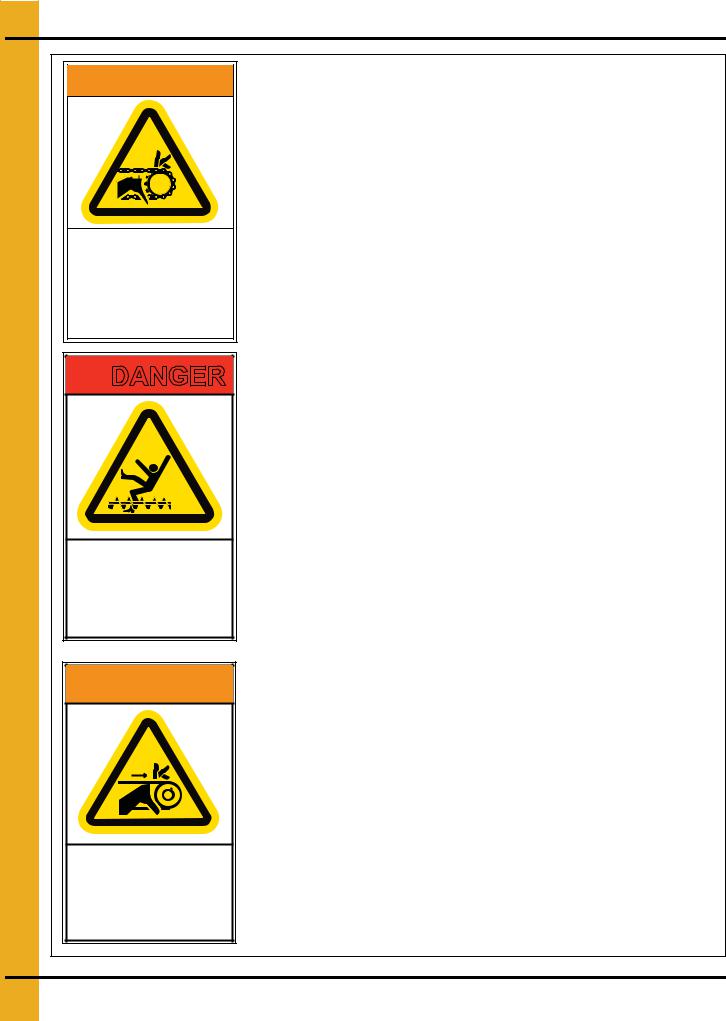
Moving parts can crush and cut. Keep hands clear. Do not operate without guards in place. Failure to do so could result in serious injury.
Decal: DC-972
Decal DC-972 is located on the bottom auger belt guard and the front bearing plate (which is visible when the bottom auger belt guard is removed).
An alternate location would be at the rear of the dryer for portable dryers equipped with the Front Discharge Option.
GSI Group 217-226-4421 |
DC-972 |
 DANGER
Rotating auger will crush and cut. Auto equipment can start at anytime. Do not enter until electric power is locked in off position. Failure to do so will result in serious injury or death.
GSI Group 217-226-4421 |
DC-974 |
Decal: DC-974
Decal DC-974 has several different locations. Two are located on the front end panel below the fan/heater. Two are located on the rear end panel below the rear access door. Two are located on the auger discharge box (one on the outside top and one on the inside of the flapper lid next to the discharge mercury switch). One more of these decals is located inside the plenum on the rear plenum closure door just inside the rear access door.
 WARNING
Automatically controlled belt drive can start at anytime. Keep hands clear. Failure to do so could result in serious injury.
GSI Group 217-226-4421 |
DC-971 |
Decal: DC-971
Decal DC-971 is located on the bottom auger belt guard and the front bearing plate (which is visible when the bottom auger belt guard is removed). An alternate location would be at the rear of the dryer for portable dryers equipped with the Front Discharge Option.
Another location for decal DC-971 is on the top of the auger belt guard (one on the belt guard cover and one on the inside belt guard body visible when the belt guard cover is removed).
10 |
PNEG-1935 Vision Hybrid for Portable Dryers |
|
2. Decals |
DANGER |
Decal: DC-973 |
Decal DC-973 is located on the rear plenum access door (inside and outside). |
Automatic equipment can start at any time. Do not enter until fuel is shut off and electrical power is locked in off position. Failure to do so will result in serious injury or death.
GSI Group 217-226-4421 |
DC-973 |
|
|
|
|
Decal: DC-1227 |
|
|
|
|
|
|
|
WARNING |
|
Decal DC-1227 is located on the |
|
|
Flame and pressure beyond |
|
fan/heater access door. |
|
|
|
|
|
|
|
door. Do not operate with |
|
|
|
|
service door removed. Keep |
|
|
|
|
head and hands clear. Can |
|
|
|
|
cause serious injury. |
|
|
|
GSI Group 217-226-4421 |
DC-1227 |
|
|
|
|
|
|
|

 WARNING
Rotating metering roll. Equipment can start automatically. Keep hands clear. Can cause serious injury. Disconnect power
before servicing.
DC-1229
Decal: DC-1229
Decal DC-1229 is located on each of the meter roll access doors.
PNEG-1935 Vision Hybrid for Portable Dryers |
11 |
2. Decals

 WARNING
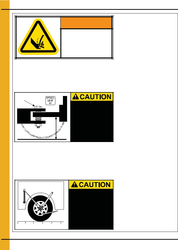
Stay clear of rotating blade. Blade could start automatically. Can cause serious injury. Disconnect power before servicing.
GSI Group 217-226-4421 |
DC-1225 |
DC-1225 |
3/4" MINIMUM BOLT DIAMETER
16-17"
Hitch pin must be securely fastened and no less than 3/4" in diameter. Failure to follow installation instructions may result in property damage.
DC-388
HUB TEMPERATURE |
|
NO GREATER THAN 150°F |
TIGHTEN TO |
|
|
150° |
90FT-LBS. |
|
Dryer must be
|
|
|
|
|
|
towed empty and |
|
|
|
|
|
|
in accordance |
|
|
|
|
|
60 PSI |
with state and |
|
|
|
|
|
COLD |
provincial |
|
|
|
|
|
|
|
0 |
50 |
100 |
150 |
200 |
250 |
regulations. |
CHECK AFTER 50 MILES AND EVERY 200 MILES |
DC-1249 |
|||||
Decal: DC-1225
Decal DC-1225 is located on the fan/heater access door.
Decal: DC-388
Decal DC-388 is located on the hitch tongue.
Decal: DC-1249
Decal DC-1249 is located on the hitch tongue.
12 |
PNEG-1935 Vision Hybrid for Portable Dryers |
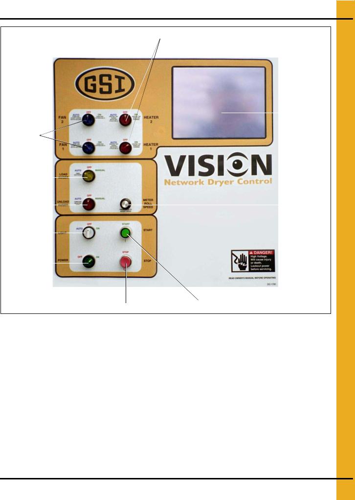
3. Vision Control Panel
Heater switches
Touch screen
Fan switches

|
Load switch |
|
|
|
|
|
|
|
|
|
|
|
|
|
|
|
|||
|
|
|
|
|
|
|
|
|
|
|
Unload switch |
|
|
|
|
|
Meter Roll |
||
|
|
|
|
|
|
Adjustment |
|||
|
|
|
|
|
|
||||
|
|
|
|
|
|
|
|
|
|
Outside |
|
|
|
||||||
Light switch |
|
|
|
|
|
||||
|
|
|
|
|
|
|
|
||
|
Control |
|
|
|
|||||
|
Power switch |
|
|
|
|
|
|||
Stop button |
Start switch |
|
Figure 3A
Control Power Switch
The Vision control system is turned ON or OFF with this switch.
NOTE: This switch does not disconnect the power that is present at the breakers, contactors, transformer(s), fuses or other electrical components found in the upper and lower control boxes. Turn the main disconnect handle to the OFF position prior to servicing any of the installed components.
Stop Button
This button stops all dryer functions. If an automatic dryer shutdown occurs, first determine and correct the cause of the shutdown. Then, press the Stop button to reset the dryer before restarting.
PNEG-1935 Vision Hybrid for Portable Dryers |
13 |

3. Vision Control Panel
Outside Light Switch
The dryers outside service light is turned ON or OFF here. It also can be set on AUTO, which turns the light ON while the dryer is running and OFF if a shutdown occurs.
Start Button
Push the Start button and all of the selector switches on the control panel will be activated.
Unload Switch
The Unload switch turns the metering rolls and discharge auger ON or OFF and selects the operation of the metering rolls. In the MANUAL position, the meter rolls will operate in one Speed only. In the AUTO position, the meter rolls switch to a multi-speed mode for moisture control operation. The switch will illuminate whenever the load auger is operating.
NOTE: If the unload auxiliary controls are being used, this switch will also control the operation of the auxiliary equipment.
Meter Roll Adjustment
This knob allows the user to adjust the meter roll setpoint(s). Pressing the knob will bring up the “Modifying Meter Roll Speed Setpoints” screen. (See Figure 3B.)
Figure 3B
NOTE: Screen may vary depending on the moisture control scheme selected.
Turning the knob clockwise will adjust the selected (red color) setpoint in a positive direction and vice versa. Pressing the knob will switch between setpoints.
14 |
PNEG-1935 Vision Hybrid for Portable Dryers |

3. Vision Control Panel
Here, you will find the following options:
Speed Adjust buttons: These are used to adjust the setpoints if the Meter Roll Knob is disabled by the software. For instructions on doing this, see Operations Chapter on Page 21.
Accept/Exit: To store the parameters and exit the screen. Cancel/Exit: To disregard the changes and exit the screen.
Load Switch
This is used to select the operation of the fill auger. In both the AUTO and MANUAL positions, the load auger will operate if the dryer is low on grain and will automatically shut OFF when the dryer is full. In the AUTO position, the dryer will shutdown if the out of grain timer expires. The load delay is disabled when the Load switch is in the MANUAL position. The switch will illuminate whenever the load auger
is operating.
Fan Switch
Each fan can be selected as ON, OFF or AUTO. The ON position operates the fan continuously during staged batch and continuous flow modes. The AUTO position operates the fan in staged batch during the dry and cool cycle, but the fan will turn OFF during the unload cycle. This switch will illuminate whenever the Air Pressure switch, located in the proper plenum chamber, is sensing air pressure.
NOTE: The bottom fan on the dryer is always Fan one.
Heater Switch
Each heater can be selected as ON, OFF or AUTO with this switch. The AUTO position activates the burner in staged batch during the dry cycle only. The ON position will activate the burner when the fan is running and if air pressure is detected. The switch will illuminate only when the flame sensor detects the flame.
NOTE: The bottom heater on the dryer is always Heater one.
PNEG-1935 Vision Hybrid for Portable Dryers |
15 |
4. Boot Screen
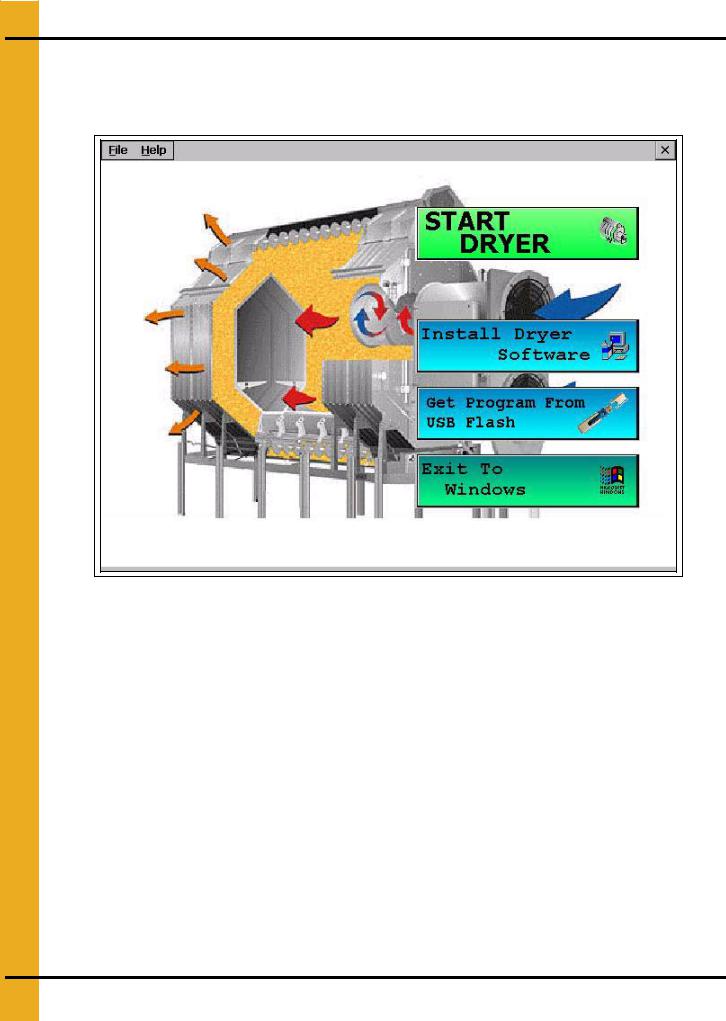
Boot Screen Description and Button Explanations
Turning the Control Power switch to the ON position, will start the Vision computer. The first screen to appear will be the Boot Screen. Notice that there are four (4) buttons on the Boot Screen. (See Figure 4A.)
Figure 4A
1.Start Dryer: This button accesses the dryer program.
2.Install Dryer Software: This button is used in updating the Vision software, which is described further in this chapter.
3.Get Program From USB Flash: This button is used in updating the Vision software, which is described further in this chapter.
4.Exit To Windows: This button should NOT be used in normal operation. Only the GSI Group employees should press this button. Turn the Control Power switch OFF, then ON if this button is inadvertently pushed to return to the regular Boot Screen.
16 |
PNEG-1935 Vision Hybrid for Portable Dryers |
4. Boot Screen
Software Update Procedure
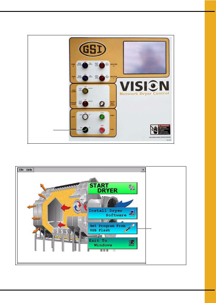
1. Cycle the Control Power switch. The Vision computer will start. (See Figure 4B.)
Control
Power switch
Figure 4B
2. When the “Boot Screen” appears, touch the “Get Program From USB Flash” button. (See Figure 4C.)
Get Program From
USB Flash button
Figure 4C
PNEG-1935 Vision Hybrid for Portable Dryers |
17 |
4.Boot Screen
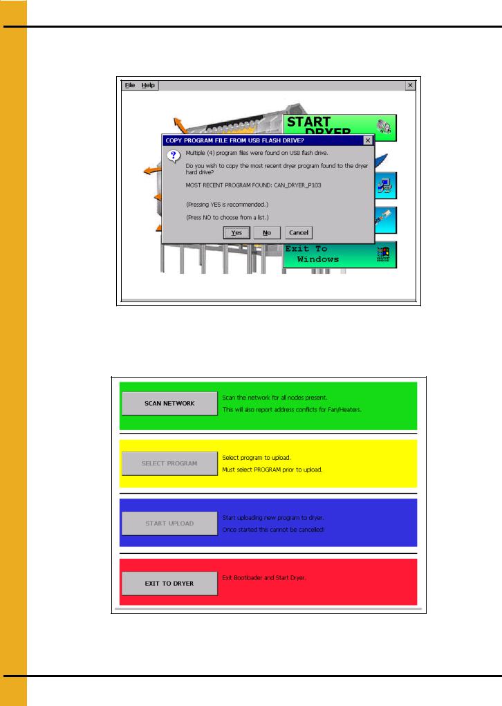
3.Insert USB flash drive into USB port.
4.The display will now confirm that program files were found.
Figure 4D
Press “Yes” to copy.
5. After the program files are transferred, the “Boot Loader” screen will appear. (See Figure 4E.)
Figure 4E
18 |
PNEG-1935 Vision Hybrid for Portable Dryers |
4. Boot Screen
Select the “Scan Network” button. This scan will check the dryer to make sure all parts of the control system are communicating directly.
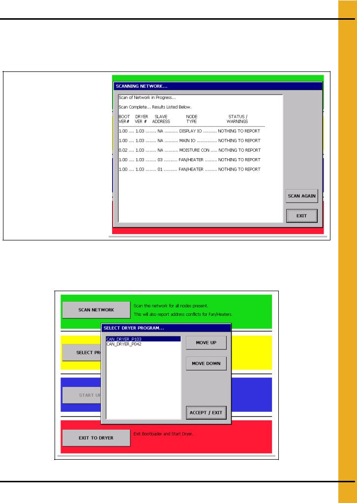
6.After the scan is complete, the Display I/O, Main I/O, Moisture Control and the Fan/Heater(s) should be shown as “Nothing to Report”. (See Figure 4F.)
NOTE: A Display I/O, Main I/O, Moisture Control and one entry for each Fan/Heater on the dryer should appear.
Figure 4F
Touch the “Exit” button.
7. Choose the “Select Program” button from the “Boot Loader” screen. (See Figure 4G.)
Figure 4G
PNEG-1935 Vision Hybrid for Portable Dryers |
19 |
4.Boot Screen
8.Select the program file you wish to upload by touching the “Move Up” and “Move Down” buttons until the desired program file is highlighted. Then, choose the “Accept/Exit” button.
9.Touch the “Start Upload” button.
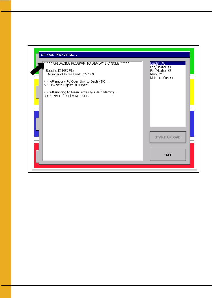
10.When the “Upload Progress” screen appears, select the “Start Upload” button. (See Figure 4H.)
Figure 4H
11.The Vision computer will now begin programming each of the network circuit boards on the dryer. The box on the right of the screen lists the network circuit boards detected in the scan. Each circuit board listed will have to be reprogrammed, so this may take a few minutes. File upload progress for the circuit board that is highlighted is displayed in the box on the left. (See Figure 4H.)
12.Once the upload is complete, choose the “Exit to Dryer” button to leave the “Boot Loader” screen and start the dryer.
13.The dryer will begin running the program that was just installed.
14.The dryer control is now ready to operate the dryer.
15.In the event it is determined that reversion to the previous software version is necessary, go back to the Boot Screen and select “Install Dryer Software” and follow the instructions above to re-install the previous software.
20 |
PNEG-1935 Vision Hybrid for Portable Dryers |
5. Operations
Operations
NOTE: The following screenshots are taken from various models of portable dryers, explaining why the picture on the screen in this manual, may be different than that of the display.
Default Operation Screen
Dryer Status
Dryer Operation
Animation
Dryer Status
Charts
Plenum(s)
Configuration
Buttons
Figure 5A
The “Operation Screen” is divided into five (5) sections. (See Figure 5A.)
1.Dryer Operation Animation: Located on the left side of the “Operation Screen”, the dryer operation animation shows the status of the fans/heaters, load and unload augers and meter rolls. It will also display the grain temperature, moisture content, moisture control setpoint and the bushel counter.
2.Dryer Status: Located at the very top of the right side of the “Operation Screen”, the dryer status will tell the user if the dryer is stopped, started, loading or unloading.
3.Dryer Status Chart: This chart, located directly under dryer status, will show the grain temperature, moisture in/out, temperature out and meter roll output (M.R.O) over a period of time.
4.Plenum(s): Located directly below dryer status chart, the plenum section will show temperature setpoint, actual plenum temperature and burner status.
5.Configuration Buttons: Select from “Timers”, “Temp”, “Setup”, “View” and “M/C” buttons.
PNEG-1935 Vision Hybrid for Portable Dryers |
21 |

5. Operations
Timers Button
Select the  button. A new screen will appear called the “Select Timer to Modify” screen. (See Figure 5B.) There are five (5) timers that can be modified.
Figure 5B
1.Load Delay: (Default setting - 2 minutes) This delay is used to prevent the load auger from over-cycling. The load delay is active only when the Load switch is in the AUTO position. The timer starts when the dryer calls for grain.
2.Out Of Grain (OOG) Timer: (Default setting - 8 minutes) The “OOG” timer should be set to the maximum time it takes for the dryer to refill during continuous or batch drying modes. The computer will display the time required to fill the dryer on the previous load, aiding you in setting an accurate time. If the dryer runs out of grain while the Load switch is in the AUTO position, the “OOG” timer automatically shuts off the dryer after the period of time preset on the timer.
3.Fan Delay: (Default setting - 3 seconds) The “Fan Delay” timer controls the amount of time between each fan startup to reduce the dryer inrush amperage.
4.Unload Delay: (Default setting - 1 minute) The “Unload Delay” timer is used to regulate the amount of time the unload auger runs after the metering rolls stop.
5.Cool Down: (Default setting - zero seconds) The dryer fans will operate for a “Cool Down” period in the event that the dryer experiences a shutdown, other than that of a plenum, grain high temperature or fan motor overload situation. The dryer can also be restarted by pressing the “Start” button on the front of the Vision control panel. This prevents the fans from shutting down because of nuisance warnings.
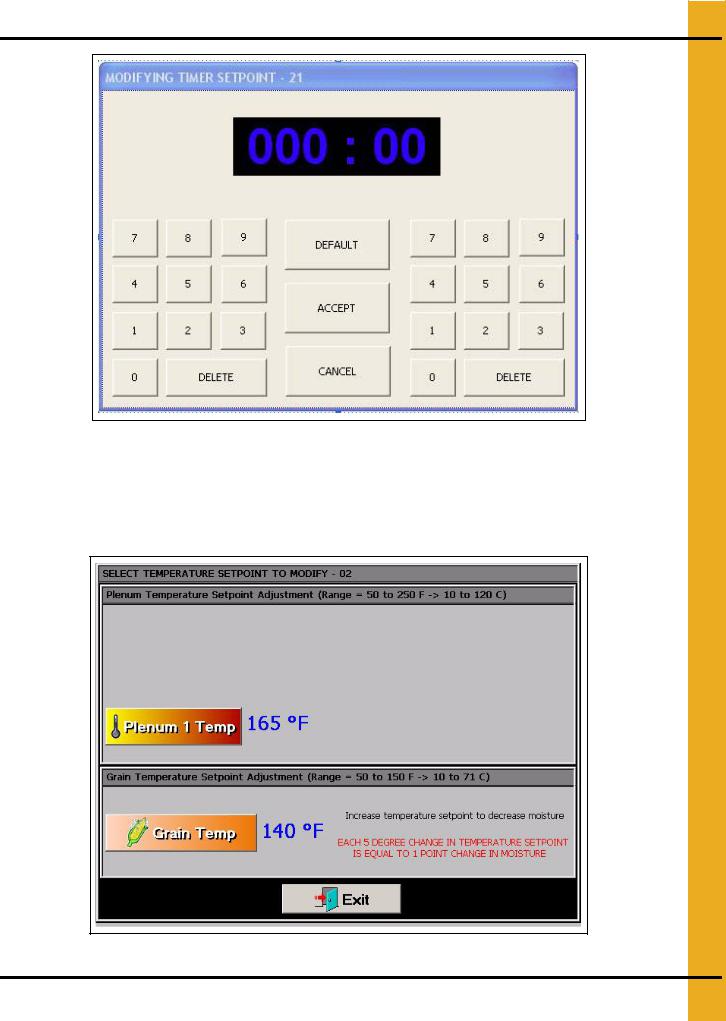
To change a timer setpoint, touch the button of the timer you wish to modify. The “Modifying Timer Setpoint” screen will then be displayed, which is shown in Figure 5C on Page 23. The left number pad is used to modify the minutes and the right number pad will modify the seconds. Touching the “Default” button will automatically set the timer to the default setpoint for that timer. The “Accept” button will save the displayed time as the setpoint. Choosing “Cancel” will exit the “Modifying Timer Setpoint” screen without saving any changes and the timer will stay at the currently saved setpoint.
22 |
PNEG-1935 Vision Hybrid for Portable Dryers |
5. Operations
Figure 5C
Temp Button
To adjust the temperature setpoints, touch the  button at the bottom of the “Operation Screen”. A new screen will appear called the “Select Temperature Setpoint to Modify” screen. (See Figure 5D.)
Figure 5D
PNEG-1935 Vision Hybrid for Portable Dryers |
23 |

5. Operations
Modify the setpoint for each of the temperatures by selecting the corresponding button.
Plenum Temperature Setpoint - Press the “Plenum X Temp” button to change the individual plenum setpoints. The “X” refers to a number between 1 and 6. Plenum #1 refers to the heater closest to the ground.
Grain Temperature Setpoint - This setpoint is used for all temperature based moisture control schemes. For more information, see the Moisture Control Options Chapter on Page 38.
The plenum temperature setpoint range is 50 F-250 F. The current temperature setpoint is displayed next to the corresponding “Plenum” button.
The grain temperature setpoint range is 50 F-160 F. The current temperature setpoint is displayed next to the “Grain Temperature” button.
Touch the desired plenum button of the setpoint you wish to change. The “Modifying Temperature Setpoint” screen will appear. (See Figure 5E.)
Figure 5E
Enter the desired temperature using the displayed number pad, then touch the “Accept” button. Touching the “Cancel” button will return you to the “Select Temperature Setpoint to Modify” screen without saving changes.
24 |
PNEG-1935 Vision Hybrid for Portable Dryers |
5. Operations
Setup Button
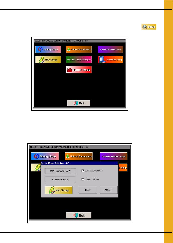
The Setup screen will allow you to configure other parameters of the dryer. To access the “Select Hardware Setup Parameter to Modify” screen, also known as the “Setup Screen”, touch the button. (See Figure 5F.)
Figure 5F
The following list can be modified:
1.Drying Mode: The  button will display the “Drying Mode Selection” window. Select continuous flow or staged batch. A check mark is displayed next to the currently selected drying mode. (See Figure 5G.)
Figure 5G
PNEG-1935 Vision Hybrid for Portable Dryers |
25 |

5.Operations
2.Moisture Control Setup:  The moisture control setup operations are described in greater detail in the Moisture Control Options Chapter on Page 38.
Figure 5H
Figure 5I
3.Unload Parameters: 
a.Set Maximum Unload Rate: The meter roll speed setpoint cannot be set higher than this value. This prevents choking downstream augers.
b.Set Minimum Unload Rate: The meter roll speed setpoint cannot be set lower than this value.
(See Figure 5J.)
Figure 5J
26 |
PNEG-1935 Vision Hybrid for Portable Dryers |

5. Operations
4.Plenum Temp Manager:  This will reduce the plenum temperature setpoint(s) if the unload rate reaches its maximum allowable value for the time specified by the “Time Between Steps” menu. Once the time has been exceeded, the dryer will reduce the temperature setpoint(s) by the value given in the “Size of Temperature Step”. If the unload rate falls below the maximum allowable value for the “Time Between Steps” period, the temperature setpoint(s) will be increased by the “Size of Temperature Steps” until the original setpoints are met. (See Figure 5K.)
NOTE: Default setting is “OFF”.
Figure 5K
5. Burner Mode: The  button will display the “Select Burner Mode” screen. (See Figure 5L.)
Figure 5L
NOTE: The bottom heater is always Heater one.
PNEG-1935 Vision Hybrid for Portable Dryers |
27 |
5. Operations
The “Select Burner Mode” screen will allow the operator to select the type of burner operation for each burner. The user has three (3) options: HI/LO, ON/OFF and AUTO modes.
a.HI/LO Mode (Default Setting): The burner will switch from high heat to low heat when the plenum temperature setpoint has been reached.
b.ON/OFF Mode: The burner will shut OFF when the upper temperature setpoint has been reached and turn back on when the lower temperature setpoint has been met.
NOTE: Useful for low plenum temperature settings in warm conditions.
c.AUTO Mode: All burners in HI/LO will be started. If the burner stays in “Low-Fire” for 60 seconds or the plenum temperature exceeds the setpoint plus 20° for 10 seconds, that burner will switch to ON/OFF operation.
NOTE: Useful in very warm ambient temperature conditions.
To select modes, touch the “Select” button for the fan/heater you wish to change. Touching the “ALL HI/LO” button will set all burners to HI/LO and the same procedure can be duplicated for the “ALL ON/OFF” and “ALL AUTO” buttons. Choose the “ACCEPT” button to save any changes and return to the “Setup Screen” or choose “CANCEL” to return to the “Setup Screen” without saving any changes.
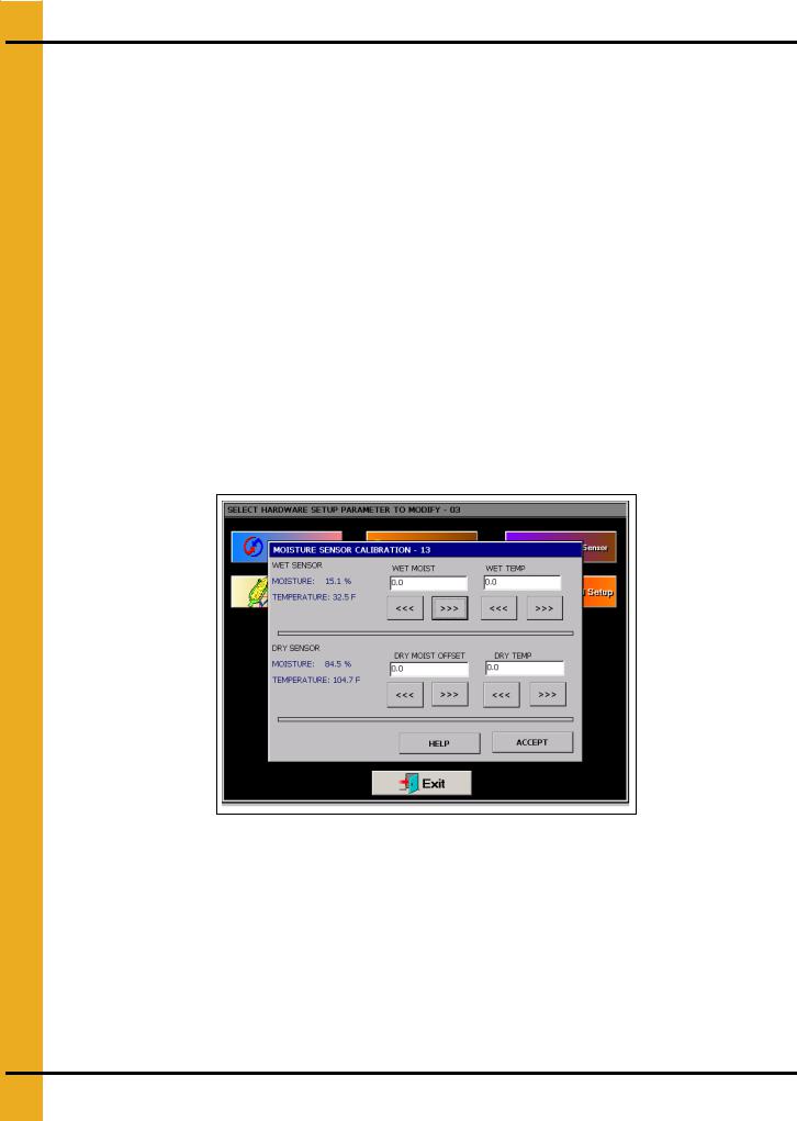
6.Calibrate Moisture Sensor:  There are two (2) moisture/temperature sensors per dryer - one for incoming grain (wet) and another for outgoing (dry). Each device has one moisture and one temperature sensor included. (See Figure 5M.)
Figure 5M
Calibrating moisture: Take several moisture samples of the grain over an extended period of time, average these values and calibrate the sensors accordingly.
Example: If the dryer’s exiting moisture (dry) is reported at 15.5% on the Vision screen and the averaged samples yielded a value of 15%, then the calibration screen would be used to enter -0.5% as the “Dry Moist Offset”.
Calibrating temperature: Take several temperature samples of the grain over an extended period of time, average these values and calibrate the sensor accordingly.
Example: If the dryer’s incoming temperature (wet) is reported to be 105°F on the Vision screen and the average samples yield a value of 100°F, adjust the “Dry Temp” to -5.
28 |
PNEG-1935 Vision Hybrid for Portable Dryers |
Loading...