


Grason-Stadler
GSI® TympStar Versions 1 and 2
Middle-Ear Analyzer
Service Manual
Reference Instruction Manual 2000-0110, Rev3.0
Printed October, 2002
GSI
|
|
|
|
|
Grason-Stadler - A Division of VIASYS Healthcare |
|
|
Grason-Stadler |
|
|
|
|
|
|
5225 Verona Road, Building 2, Madison, WI 53711 |
|
|
|
|
TEL:608-441-2323,800-700-2282,FAX:608-441-2234 |
|
|
|
|
|
|
|
|
|
Title: GSI TympStar Versions 1 and 2
Middle-Ear Analyzer
Service Manual
Date: |
October, 2002 |
Copyright © 2001 Grason-Stadler. All rights reserved. No part of this publication may be reproduced or transmitted in any form or by any means without the prior written permission of Grason-Stadler. The information in this publication is proprietary to Grason-Stadler.
Part number: |
2000-0110 |
|
|
Printing history: |
November, 2001 |
First printing |
Rev 1.0 |
|
June, 2002 |
Second printing |
Rev 2.0 |
|
October, 2002 |
Thirdprinting |
Rev 3.0 |

Warranty for the GSI TympStar Versions 1 & 2
Grason-Stadler warrants the GSI TympStar Versions 1 and 2 to be free of original defects in material and workmanship and to perform in accordance with manufacturer’s specifications for a period of one year from the date of purchase. If this instrument or any component thereof is found to be defective or at variance from the manufacturer’s specifications during the warranty period, Grason-Stadler will repair, replace, or recalibrate the instrument or component at no cost to the purchaser.
This warranty only applies to instruments purchased new from Grason-Stadler or its authorized distributors or representatives. The purchaser must return the instrument directly to Grason-Stadler or an authorized GSI TympStar distributor or representative and bear the costs of shipping.
This warranty does not cover breakage or failure due to tampering, misuse, neglect, accidents, modification, or shipping, and is void if the instrument is not used in accordance with manufacturer’s recommendations or if repaired or serviced by other than Grason-Stadler or a Grason-Stadler authorized representative.
WARNING
The GSI TympStar Versions 1 and 2 are designed to be used with a hospital grade outlets. Injury to personnel or damage to equipment can result when a three-prong adapter is connected between the instruments’s power plug and an A/C outlet or extension cord.
Accessory Hazard Warning
This IEC 601-l/CSA C22.2 No. 601.1M90 listed medical instrument should be interconnected with accessories that have proper electrical compatibility and which are listed as conforming to Part 1: General Requirements for Safety of the UL Medical Electrical Equipment Standard UL2601-1. Connection of accessories not meeting these requirements may result in electrical leakage currents in excess of those allowed by the standard and present a potential electrical shock hazard to the person being tested.

User manuals |
Installation, setup and |
operating information can be found in the Reference |
|
Instruction Manuals: |
|
|
TympStar Version 1: |
2000-0100 |
|
TympStar Version 2: |
2000-0120 |
Service personnel |
Repair and/or bench testing of the GSI TympStar Version 1 and Version 2 |
|
|
instruments should be performed only by trained personnel. The following |
|
|
instructions are provided primarily for use by persons who are skilled in the |
|
|
repair of electronic equipment. |
|
Electrical safety |
CAUTION |
|
|
The GSI TympStar Version 1 and Version 2 instruments are |
|
|
IEC 601-1/CSA approved; consequently if any parts are re- |
|
|
placed during the repair of these units, only exact replace- |
|
|
ments should be made. Any alterations of the present elec- |
|
|
trical or mechanical construction or components will void |
|
|
these safety approvals. |
|
CMOS handling |
Many of the integrated circuits on the PC Boards are constructed of CMOS |
|
|
and NMOS materials. Please observe the following precautions: |
|
CAUTION
Failure to observe the following precautions whenever a circuit board or an integrated circuit package is handled can result in damage to the GSI TympStar Version 1 or Version 2 instrument. Please observe these precautions:
1) Place the instrument and parts on a grounded, conductive work surface.
2) Ground yourself (with a strap having about 1 Meg-Ohm resistance) to discharge or prevent static charges.
3) Ground the frame of any test instrument or soldering iron to be used. 4) If any circuit boards are to be stored or transported, enclose them in
conductive (antistatic) envelopes.

Contents
Introduction .................................. |
1-1 |
General ..................................................................................................................... |
1-1 |
Version 1 ................................................................................................................... |
1-2 |
Version 1 equipment connections and options ..................................................... |
1-2 |
Version 2 ................................................................................................................... |
1-3 |
Version 2 equipment connections and options ..................................................... |
1-3 |
The probe ................................................................................................................. |
1-4 |
Instrument controls ................................................................................................. |
1-5 |
Hardkeys and softkeys ......................................................................................... |
1-5 |
Rotary pressure control ....................................................................................... |
1-5 |
Test modes and menu navigation .......................................................................... |
1-5 |
Changing parameter settings.................................................................................. |
1-7 |
Menu diagrams ........................................................................................................ |
1-7 |
GSI default parameter settings ............................................................................... |
1-7 |
Specifications ............................... |
2-1 |
Introduction .............................................................................................................. |
2-1 |
Standards ................................................................................................................. |
2-1 |
Version 1 Specifications ................................................... |
2-1 |
Sensitivity ranges .................................................................................................... |
2-2 |
Probe signal ............................................................................................................. |
2-2 |
Pneumatic System ................................................................................................... |
2-3 |
Acoustic Reflex Activating (Stimulus) Signal ......................................................... |
2-3 |
Stimulus Presentation Control ................................................................................ |
2-5 |
Temporal Specifications of Stimulus Presentation ............................................... |
2-5 |
Environmental .......................................................................................................... |
2-6 |
Warm-Up Time.......................................................................................................... |
2-6 |
Calibration Stability .................................................................................................. |
2-7 |
Connectors ............................................................................................................... |
2-7 |
Electrical ................................................................................................................... |
2-8 |
Supplied Accessories .............................................................................................. |
2-9 |
Mechanical ............................................................................................................... |
2-9 |
Materials of manufacture ........................................................................................ |
2-9 |
GSI TympStar Version 1 and Version 2 Service Manual |
Contents - 1 |
Table of Contents |
|
Calibration requirements ......................................................................................... |
2-9 |
Version 2 Specifications ................................................. |
2-10 |
Standards ............................................................................................................... |
2-10 |
Sensitivity ranges .................................................................................................. |
2-11 |
Temporal Latency in ARLT Mode .......................................................................... |
2-12 |
Multi Frequency ..................................................................................................... |
2-12 |
Probe Signal (Sinusoidal) ...................................................................................... |
2-12 |
Pneumatic System ................................................................................................. |
2-13 |
Acoustic Reflex Activating (Stimulus) Signal ....................................................... |
2-13 |
Click Stimulus ........................................................................................................ |
2-16 |
Stimulus .................................................................................................................. |
2-16 |
Presentation Control.............................................................................................. |
2-16 |
Temporal Specifications Of Stimulus Presentation ............................................ |
2-17 |
Environmental ........................................................................................................ |
2-17 |
Warm-Up Time........................................................................................................ |
2-17 |
Calibration Stability................................................................................................ |
2-18 |
Connectors ............................................................................................................. |
2-18 |
Electrical ................................................................................................................. |
2-19 |
Supplied Accessories ............................................................................................ |
2-20 |
Mechanical ............................................................................................................. |
2-20 |
Materials of manufacture ...................................................................................... |
2-20 |
Calibration requirements ....................................................................................... |
2-20 |
Operation summary...................... |
3-1 |
Front panel controls ......................................................... |
3-1 |
Hardkeys................................................................................................................... |
3-2 |
Tymp .................................................................................................................... |
3-2 |
Reflex ................................................................................................................... |
3-2 |
Etf ......................................................................................................................... |
3-2 |
Special ................................................................................................................. |
3-2 |
Page ..................................................................................................................... |
3-2 |
Print ...................................................................................................................... |
3-2 |
Remote ................................................................................................................. |
3-2 |
Data Transfer ....................................................................................................... |
3-2 |
Pressure control ................................................................................................... |
3-2 |
Manual ................................................................................................................. |
3-2 |
Hold ...................................................................................................................... |
3-2 |
Stop ...................................................................................................................... |
3-2 |
Start ...................................................................................................................... |
3-3 |
Stimulus ............................................................................................................... |
3-3 |
Intensity ................................................................................................................ |
3-3 |
Contents - 2 |
Grason-Stadler |
Table of Contents |
|
Present ................................................................................................................. |
3-3 |
LCD hardkeys........................................................................................................... |
3-3 |
Clear .................................................................................................................... |
3-3 |
Erase .................................................................................................................... |
3-3 |
Return................................................................................................................... |
3-3 |
Softkeys .................................................................................................................... |
3-3 |
Menus and LCD screens ................................................. |
3-4 |
Menus ....................................................................................................................... |
3-4 |
Program modes........................................................................................................ |
3-5 |
Version 1 probe tone frequencies .......................................................................... |
3-5 |
Version 2 probe tone frequencies .......................................................................... |
3-5 |
Version 1 LCD graphic traces ................................................................................. |
3-5 |
Version 2 LCD graphic traces ................................................................................. |
3-5 |
Probe lights .............................................................................................................. |
3-6 |
LCD screen ............................................................................................................... |
3-6 |
Erasing and clearing test data ................................................................................ |
3-7 |
Version 2 External reflex test stimuli ..................................................................... |
3-7 |
Paging test data ....................................................................................................... |
3-7 |
Version 2 cursor....................................................................................................... |
3-8 |
Printing tests ............................................................................................................ |
3-8 |
Preparing an external printer .................................................................................. |
3-8 |
Setting the printer parameters .............................................................................. |
3-9 |
Left column printout data .................................................................................... |
3-10 |
Color or black and white .................................................................................... |
3-10 |
Changing Instrument Versions ....................................... |
3-11 |
Changing from a Version 2 to a Version 1 ........................................................... |
3-11 |
Switching to V1 temporarily................................................................................ |
3-12 |
Switching back to V2 .......................................................................................... |
3-12 |
Switching to V1 permanently .............................................................................. |
3-12 |
Changing from a Version 1 to a Version 2 ........................................................... |
3-13 |
Obtaining a License Code .................................................................................. |
3-14 |
Replacing the V1 Probe with a V2 Probe ........................................................... |
3-15 |
Switching to Version 2 software ......................................................................... |
3-16 |
Version 1 test procedures .............................................. |
3-17 |
Tymp diagnostic..................................................................................................... |
3-17 |
Manual Tymp .......................................................................................................... |
3-17 |
Tymp screening ..................................................................................................... |
3-18 |
Reflex threshold ..................................................................................................... |
3-18 |
Automatic Auto Zero ........................................................................................... |
3-18 |
Mark Threshold .................................................................................................. |
3-19 |
Reflex Threshold Seeking .................................................................................. |
3-19 |
Reflex decay ........................................................................................................... |
3-20 |
Eustachian tube function ...................................................................................... |
3-20 |
Pressure Swallow Test (intact TM) ..................................................................... |
3-20 |
GSI TympStar Version 1 and Version 2 Service Manual |
Contents - 3 |
Table of Contents |
|
Perforated Ear Test (Perforated TM) .................................................................. |
3-20 |
Auto sequence testing .......................................................................................... |
3-21 |
Programming auto sequence tests ...................................................................... |
3-21 |
Version 2 test procedures .............................................. |
3-22 |
Tymp diagnostic..................................................................................................... |
3-22 |
Manual tymp ........................................................................................................... |
3-23 |
Tymp screening ..................................................................................................... |
3-23 |
Reflex threshold ..................................................................................................... |
3-24 |
Automatic auto zero ........................................................................................... |
3-25 |
Mark Threshold .................................................................................................. |
3-25 |
Reflex Threshold Seeking .................................................................................. |
3-25 |
Reflex decay ........................................................................................................... |
3-26 |
Acoustic reflex latency test (ARLT) ...................................................................... |
3-26 |
Acoustic reflex sensitization (A.R. SENSI) ........................................................... |
3-27 |
Eustachian tube function ...................................................................................... |
3-28 |
Pressure Swallow Test (intact TM) ..................................................................... |
3-28 |
Perforated Ear Test (Perforated TM) .................................................................. |
3-28 |
Multiple frequency tympanometry (MULTIPLE Hz) ............................................. |
3-29 |
Auto sequence testing .......................................................................................... |
3-30 |
Programming auto sequence tests ...................................................................... |
3-31 |
Calibration .................................... |
4-1 |
Introduction .............................................................................................................. |
4-1 |
When to calibrate the TympStar ............................................................................. |
4-2 |
Calibration requirements ......................................................................................... |
4-2 |
Complete calibration sequence ............................................................................ |
4-2 |
Routine calibration sequence ............................................................................... |
4-3 |
Preparing for calibration ................................................... |
4-4 |
Tools and equipment required ................................................................................ |
4-4 |
Cleaning the probe and Contra phone ................................................................... |
4-4 |
Probe.................................................................................................................... |
4-4 |
Contra phone........................................................................................................ |
4-5 |
Cal/Normal switch ............................................................ |
4-6 |
Cal Option DIP switch ...................................................... |
4-6 |
Switch 1: Factory use only ................................................................................... |
4-7 |
Switch 2: GSI/custom RTL transducer calibration.............................................. |
4-7 |
Switch 3: Unused ................................................................................................... |
4-7 |
Switch 4: Unused ................................................................................................... |
4-7 |
Switch 5: Unused ................................................................................................... |
4-7 |
Switch 6: Diagnostic mode ................................................................................... |
4-8 |
Contents - 4 |
Grason-Stadler |
Table of Contents |
|
Hardware Diagnostics ............................................................................................. |
4-8 |
DAC LEVELS ....................................................................................................... |
4-9 |
IPSI SOURCE..................................................................................................... |
4-11 |
IPSI ON/OFF ...................................................................................................... |
4-11 |
CONTRA SOURCE ............................................................................................ |
4-11 |
CONTRA ON/OFF............................................................................................. |
4-12 |
MUX INPUTS ..................................................................................................... |
4-12 |
PROBE/FILER .................................................................................................... |
4-13 |
ROUTING ........................................................................................................... |
4-14 |
PROBE ON/OFF ................................................................................................ |
4-15 |
PORTS DIAG. .......................................................................................................... |
4-15 |
RS-232 INT. ON/OFF ......................................................................................... |
4-15 |
RS-232 INT. ON/OFF ......................................................................................... |
4-16 |
PARALLEL ON/OFF ........................................................................................... |
4-16 |
MISC. DIAG ............................................................................................................. |
4-17 |
CALENDAR CLOCK ........................................................................................... |
4-18 |
DISPLAY & LEDS ............................................................................................... |
4-20 |
KEYS .................................................................................................................. |
4-21 |
DIP SWITCHES .................................................................................................. |
4-22 |
EEPROM ............................................................................................................ |
4-22 |
SOFTWARE TIMER ........................................................................................... |
4-23 |
WATCHDOG TIMER .......................................................................................... |
4-24 |
ERROR LOG ........................................................................................................... |
4-25 |
Switch 7: Self-Cal.................................................................................................. |
4-26 |
Switch 8: Load default calibration data............................................................... |
4-26 |
Probe serial number....................................................... |
4-26 |
Resolving problems ....................................................... |
4-27 |
Calibration procedures................................................... |
4-28 |
Hardkeys ............................................................................................................ |
4-28 |
Softkeys ............................................................................................................. |
4-29 |
Printing calibration sheets .................................................................................. |
4-30 |
Adjusting Cal HL and Target SPL levels............................................................. |
4-31 |
Custom transducers .............................................................................................. |
4-32 |
Transducerconnections ........................................................................................ |
4-32 |
Calibration requirements ....................................................................................... |
4-33 |
Complete calibration sequence .......................................................................... |
4-33 |
Routine calibration sequence ............................................................................. |
4-33 |
TympStar Version 1 Calibration...................................... |
4-33 |
Version 1 Calibration Procedures................................... |
4-34 |
Self-Cal ................................................................................................................... |
4-34 |
Loading default data .............................................................................................. |
4-35 |
Contra, Ipsi and Probe tone calibration ............................................................... |
4-36 |
Contra SPL Cal .................................................................................................. |
4-36 |
GSI TympStar Version 1 and Version 2 Service Manual |
Contents - 5 |
Table of Contents |
|
Ipsi SPL Cal ....................................................................................................... |
4-37 |
Probe Tone SPL Cal............................................................................................... |
4-38 |
Y Cal ........................................................................................................................ |
4-39 |
Altitude Cal ......................................................................................................... |
4-39 |
Pressure Cal ........................................................................................................... |
4-41 |
Set ambient ........................................................................................................ |
4-42 |
Set -600/400 ............................................................................................................ |
4-44 |
Leak rate ............................................................................................................ |
4-45 |
Verify Cal ................................................................................................................ |
4-47 |
Diagnostic............................................................................................................... |
4-49 |
Returning to the Normal Test Mode ..................................................................... |
4-50 |
TympStar Version 2 Calibration ..................................... |
4-51 |
Calibration requirements ...................................................................................... |
4-51 |
Complete calibration sequence .......................................................................... |
4-51 |
Routine calibration sequence............................................................................. |
4-51 |
Version 2 Calibration Procedures .................................. |
4-52 |
Self-Cal ................................................................................................................... |
4-52 |
Loading default data........................................................................................... |
4-53 |
Contra, Ipsi and Probe tone calibration ............................................................... |
4-54 |
Contra and Ipsi Cal ............................................................................................ |
4-54 |
External Input Calibration ................................................................................... |
4-55 |
Click Calibration ................................................................................................. |
4-55 |
Contra SPL Cal ....................................................................................................... |
4-56 |
Ipsi Channel ....................................................................................................... |
4-56 |
Contra Channel .................................................................................................. |
4-57 |
Ipsi SPL Cal ............................................................................................................ |
4-59 |
Ipsi Channel ....................................................................................................... |
4-59 |
Contra Channel .................................................................................................. |
4-60 |
Probe Tone SPL Cal............................................................................................... |
4-62 |
Y/B/G Cal ................................................................................................................ |
4-64 |
Altitude Cal ......................................................................................................... |
4-64 |
Pressure Cal and diagnostics ............................................................................... |
4-66 |
Returning to Normal Test Mode ........................................................................... |
4-66 |
Disassembly ................................. |
5-1 |
Introduction .............................................................................................................. |
5-1 |
Disassembly Procedure ................................................... |
5-3 |
Tools Required ......................................................................................................... |
5-3 |
Opening the cover ................................................................................................... |
5-3 |
Removing the analog board ................................................................................... |
5-4 |
Removing the Pump ................................................................................................ |
5-6 |
Contents - 6 |
Grason-Stadler |
Table of Contents |
|
Removing the power supply................................................................................... |
5-8 |
Removing the power module ................................................................................. |
5-9 |
Fuse holder .......................................................................................................... |
5-9 |
Removing the LCD contrast control .................................................................... |
5-10 |
Removing the printer board .................................................................................. |
5-11 |
Removing the printer ............................................................................................. |
5-12 |
Removing the PC104 Board .................................................................................. |
5-15 |
Removing the digital board ................................................................................... |
5-17 |
Removing the LCD or Softkeypad cables ............................................................ |
5-20 |
Removing the LCD ................................................................................................. |
5-25 |
Removing the LCD front panel label (softkey panel) ........................................... |
5-27 |
Removing the instrument front panel label.......................................................... |
5-29 |
Removing panel keypads....................................................................................... |
5-29 |
System Level Parts ...................... |
6-1 |
General ..................................................................................................................... |
6-1 |
Assembly drawings .................................................................................................. |
6-1 |
Case/chassis ............................................................................................................ |
6-2 |
Overall assembly ..................................................................................................... |
6-4 |
LCD assembly .......................................................................................................... |
6-5 |
Top case assembly .................................................................................................. |
6-6 |
Bottom case assembly ............................................................................................ |
6-7 |
Instrument assembly ............................................................................................... |
6-8 |
Labels ....................................................................................................................... |
6-9 |
Printer Assembly .................................................................................................... |
6-11 |
Hardware description ................... |
7-1 |
General ..................................................................................................................... |
7-1 |
System boot sequence .................................................... |
7-1 |
Pre-CP Control ......................................................................................................... |
7-1 |
Main() ........................................................................................................................ |
7-1 |
Set_op_mode() ........................................................................................................ |
7-3 |
Tymp_sk() ................................................................................................................. |
7-4 |
Interconnection diagram .................................................. |
7-5 |
Block diagram description of assemblies ............................................................. |
7-6 |
LCD assembly ..................................................................................................... |
7-6 |
Printer................................................................................................................... |
7-6 |
Probe ................................................................................................................... |
7-6 |
GSI TympStar Version 1 and Version 2 Service Manual |
Contents - 7 |
Table of Contents |
|
Pump ................................................................................................................... |
7-6 |
Digital board ......................................................................................................... |
7-7 |
PC104 board ........................................................................................................ |
7-7 |
Analog board........................................................................................................ |
7-7 |
Power supply board .............................................................................................. |
7-8 |
Printer board ........................................................................................................ |
7-8 |
System assembly diagram .............................................. |
7-9 |
Troubleshooting ........................... |
8-1 |
System power supply measurements .............................. |
8-1 |
Power Supply (J2) .................................................................................................... |
8-1 |
Power Supply (set +5VDC) ...................................................................................... |
8-2 |
Analog Board (J7) .................................................................................................... |
8-2 |
Analog Board (J6) .................................................................................................... |
8-2 |
Analog Board (J10) .................................................................................................. |
8-3 |
Digital Board (J28) ................................................................................................... |
8-3 |
Digital Board (J34) ................................................................................................... |
8-3 |
Printer Board (Full View) ......................................................................................... |
8-4 |
Printer Board (J6) .................................................................................................... |
8-4 |
Printer Board (J4) .................................................................................................... |
8-4 |
Printer Board (J8) .................................................................................................... |
8-5 |
Pressure Potentiometer (Digital Board) ................................................................. |
8-5 |
Error Codes ..................................................................... |
8-6 |
CP Error codes ........................................................................................................ |
8-6 |
SP Error codes ....................................................................................................... |
8-16 |
Error Messages.............................................................. |
8-19 |
LCD problem symptoms and probable causes .............. |
8-22 |
Probe problem symptoms and probable causes ............ |
8-22 |
Pump problem symptoms and probable causes ............ |
8-23 |
Printer problem symptoms and probable causes ........... |
8-23 |
Hardware Diagnostic mode............................................ |
8-24 |
Functional description ........................................................................................... |
8-24 |
Pressure A/D MUX ................................................................................................. |
8-24 |
Mic. MUX................................................................................................................. |
8-25 |
Probe tone and filter mode ................................................................................... |
8-25 |
DAC levels .............................................................................................................. |
8-25 |
Routing ................................................................................................................... |
8-25 |
IPSI/CONTRA and OSC l/OSC 2 ............................................................................ |
8-26 |
Contents - 8 |
Grason-Stadler |
Introduction |
1 |
General |
The GSI TympStar Version 1and Version 2 Middle-Ear Analyzers are techni- |
|
|
cally advanced, computer-based admittance instruments designed to be used |
|
|
in clinical or research settings. The TympStar builds on the sophistication, |
|
|
functionality and flexibility of the GSI 33, offering unparalleled testing capa- |
|
|
bilities. It contains total capabilities for complete, manual or automatic diag- |
|
|
nostic testing for analysis of middle ear function. |
|
|
Operators have a choice of using GSI |
|
|
preprogrammed test parameters, or programming |
|
|
their own test criteria. A large liquid crystal |
|
|
display (LCD) clearly displays test param- |
|
|
eter choices and the possible alterna- |
|
|
tives. Admittance and pressure |
|
|
indications are shown on the |
|
|
LCD along with a |
|
|
continuous digital |
|
|
readout. |
Test sta- |
|
tus and |
invalid |
|
choices are also shown |
|
|
on the LCD. |
|
Test results are displayed in real-time. The user can view the results as they are being measured and then has the choice of printing the display or retesting the patient. The high-speed printer generates reports in concise graphical formats that are easy to read.
This manual addresses the service requirements of the Version 1 and the Version 2 instruments, and calls attention to the differences when necessary. Please refer to the appropriate Reference Instruction Manual for more detailed information regarding instrument installation and operation.
GSI TympStar Version 1 and Version 2 Service Manual |
1 - 1 |
|
|
|
|
Chapter 1 |
Version 1 |
Admittance (Y) may be measured with a probe tone frequency of 226 Hz. The |
|||
|
extensive battery of test mode choices include: |
|||
|
• Diagnostic Tympanometry |
|||
|
• Acoustic Reflex Threshold and Decay Measurements |
|||
|
• Eustachian-Tube Function Testing (Both intact and perforated eardrums) |
|||
|
• Screening Tympanometry/Reflex (Automatic Only) |
|||
|
The tympanometric measurement results are automatically |
|||
|
scaled and presented in equivalent ml of compliance at “Y”, |
|||
|
226 Hz. Sensitivity scales for the display of reflex mea- |
|||
|
surement results can be selected manually. A cur- |
|||
|
sor is available in all test modes for calling out |
|||
|
numeric positions on the X and Y |
|||
|
axes. |
|||
Version 1 equipment |
TympStar Version 1 options that can be |
|||
connections and |
connected to the rear panel include RS232 |
|||
options |
serial communication, a keyboard for entering patient information and a VGA |
|||
|
monitor for displaying test results. Other options offered for the TympStar |
|||
|
Version 1 for managing and archiving data, include: |
|||
|
• Internal memory for storing up to 26 test results |
|||
|
• Data export to an external PC via RS232 serial interface |
|||
|
|
|
|
|
|
|
|
|
|
|
|
|
|
|
Not used in TympStar
Version 1
1 - 2 |
Grason-Stadler |
|
|
|
|
Introduction |
Version 2 |
Admittance (Y), and its components Susceptance (B) and Conductance (G), may |
|||
|
be measured with probe tone frequencies of 226, 678, and 1000 Hz. The extensive |
|||
|
battery of test mode choices include: |
|||
|
• Diagnostic Tympanometry |
|||
|
• Acoustic Reflex Threshold and Decay Measurements |
|||
|
• Eustachian-Tube Function Testing (Both intact and perforated eardrums) |
|||
|
• Screening Tympanometry/Reflex (Automatic Only) |
|||
|
• Acoustic Reflex Latency Testing |
|||
|
• Acoustic Reflex Sensitization |
|||
|
• Multiple Frequency Tympanometry (250 Hz to 2000 Hz) |
|||
|
The tympanometric measurement results are automatically scaled and presented |
|||
|
in equivalent ml of compliance at “Y”, 226 Hz. All “B” and “G” measure- |
|||
|
ments and measurements performed at probe tone frequencies of 678 Hz and |
|||
|
1000 Hz are expressed in mmhos. Sensitivity scales for the display of reflex |
|||
|
measurement results can be selected manually. Reflex test stimuli can be in- |
|||
|
put from an external source and presented via external control. A cursor is |
|||
|
available in all test modes for calling out numeric positions on the X and Y |
|||
|
axes. |
|||
Version 2 equipment |
TympStar options that can be connected to the rear panel include an external |
|||
connections and |
stimulus source, an external Present control, RS232 serial communication, a |
|||
options |
keyboard for entering patient information and a VGA monitor for displaying |
|||
|
test results. Other options offered for the TympStar for managing and archiving |
|||
|
data, include: |
|||
|
• Internal memory for storing up to 26 test results |
|||
|
• Data export to an external PC via RS232 serial interface |
|||
|
|
|
|
|
|
|
|
|
|
|
|
|
|
|
Used only in TympStar
Version 2
GSI TympStar Version 1 and Version 2 Service Manual |
1 - 3 |

|
Chapter 1 |
The probe |
The innovative lightweight probe is designed for patient comfort, ease-of-seal, and |
|
accurate test results. A wide variety of both standard and special sized eartips are |
|
supplied with the GSI TympStar to hermetically seal the ear canal. In addition, a set |
|
of screening eartips is provided for screening tymp and reflex tests. |
|
The operator has a choice of three mountings to support the probe box; the |
|
standard lightweight shoulder mounting, standard clothes clip, or an optional |
|
operator wrist attachment. The probe box has 2 LED’s to indicate test status. |
|
Within the probe box there are two small loudspeakers, a microphone and a |
|
pressure transducer. One loudspeaker delivers the probe tone to the ear canal, |
|
while the microphone monitors the intensity of the probe tone within the ear canal. |
|
The second loudspeaker delivers the ipsilateral (ipsi) stimuli to the ear canal. |
|
The contralateral (contra) insert phone contains its own loudspeaker. The |
|
pressure within the ear canal can be varied within the range of +400 daPa |
|
to -600 daPa. At no time is it possible to exceed specified maximum |
|
limits. Pressure can be varied automatically or manually and from nega- |
|
tive to positive or from positive to negative values. Pressure within |
|
the ear canal is monitored continuously in order to maintain pressure |
|
accuracy throughout each test sequence. |
1 - 4 |
Grason-Stadler |
|
Introduction |
|
|
|||
Instrument controls |
A combination of hardkeys and softkeys are used to select the test modes and |
|||||
|
parameters and to conduct tests. |
|
|
|||
Hardkeys and softkeys |
Hardkeys are located on the front panel and the sides of the LCD panel and provide |
|||||
|
fixed functions that do not change. Softkeys are located directly under the LCD and |
|||||
|
change to support the requirements of a test session. |
|
|
|||
|
LCD panel |
|
|
|
Softkey |
|
|
|
|
||||
|
|
|
|
|
|
|
|
|
|
|
|
|
Hardkeys |
|
|
|
|
|
|
Front panel |
|
|
|
|
|
|
|
|
|
|
|
|
Pressure control |
|
Rotary pressure |
A rotary pressure control is also provided to change or fine-tune pressure within the |
|||||
control |
ear canal. |
|
|
|||
Test modes and menu |
Selecting a test mode by pressing a hardkey causes the required test screen to be |
|||||
navigation |
displayed on the LCD with the appropriate menu of test parameters shown across |
|||||
|
the bottom. The softkeys are then used in conjunction with a few hardkeys to |
|||||
|
navigate through the menus and set parameter values for the selected tests. For |
|||||
|
example, pressing the TYMP hardkey causes the Tymp Diagnostic screen to be |
|||||
Tymp hardkey |
displayed. |
|
|
|||
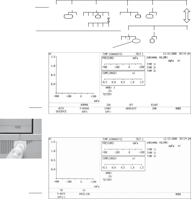
Tymp Diagnostic screen
Tymp parameter menu
GSI TympStar Version 1 and Version 2 Service Manual |
1 - 5 |
First level
Second level
First level
Second level
Chapter 1
Pressing the softkeys displayed across the bottom of the LCD allows the user to navigate through the Tymp Diagnostic parameter menus diagrammed below. These menus are from the Version 1, however, the process is the same in both versions. GSI default softkey selections are circled on menu diagrams.
The first level of parameter menu selections includes AUTO SEQUENCE, P-RANGE, START, GRADIENT, EAR and MORE.
AUTO |
P-RANGE |
START |
|
GRADIENT |
EAR |
MORE |
||
SEQUENCE |
daPa |
daPa |
|
|
|
|
|
|
|
NORMAL WIDE -600 -400 |
-200 |
+200 |
+400 |
MORE TYMP WIDTH |
RATIO OFF |
RIGHT LEFT |
|
|
|
|
|
|
daPa |
ml |
|
|
|
-500 |
-300 |
0 |
+300 |
MORE |
|
|
|
|
|
|
|
|
P-RATE |
BASELINE |
MORE |
|
|
|
|
|
|
daPa/s |
|
|
|
|
|
|
|
|
12.5 50 |
200 600/200 |
ON OFF |
|
Default selection
A second level of menus can be displayed by pressing the MORE softkey and includes P-RATE, BASELINE and MORE.
The MORE softkey is used to toggle between the top and lower levels of menus while the test screen portion above the softkeys remains unchanged.
1 - 6 |
Grason-Stadler |
Introduction
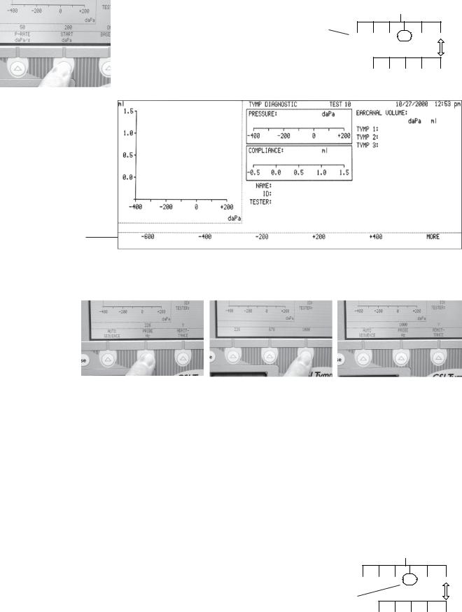
Pressing a parameter menu softkey causes a sub-menu of parameter settings to be displayed. Often submenus will also contain MORE softkey selections that provide access to additional setting alternatives.
Sub-menu of |
START |
|
|
|
daPa |
|
|
||
START daPa |
|
|
|
|
-600 -400 |
-200 |
+200 |
+400 |
MORE |
-500 |
-300 |
0 |
+300 |
MORE |
Sub-menu of
START daPa
Changing parameter |
Settings can be changed for a selected parameter by pressing the desired softkey as |
settings |
shown in this example of changing the Probe Hz from 226 to 1000. |
|
Making the new selection returns the display to the previous menu level with the new |
|
setting shown above the selected parameter. |
|
If no change is desired, the display can be returned to the previous level by |
|
pressing the RETURN hardkey. |
|
In the manner described above, menus can be navigated and settings can be |
|
changed for any of the test modes. |
Menu diagrams |
Menu structure diagrams like the diagrams shown on these pages will be used |
|
throughout the remainder of this manual as a convenience to the user. |
GSI default param- GSI default parameters are circled on eter settings menu structure diagrams shown throughout the remainder of this
manual.
START daPa
-600 -400 -200 +200 +400 MORE
GSI default value
-500 -300 0 +300 MORE
GSI TympStar Version 1 and Version 2 Service Manual |
1 - 7 |
Chapter 1
1 - 8 |
Grason-Stadler |
Specifications 2
Introduction |
Detailed specifications are provided in this chapter for the TympStar Version 1 |
|
and TympStar Version 2 instruments. The specifications for each instrument |
|
can also be found in its corresponding Reference Instruction Manual. |
Version 1 Specifications
Standards |
The GSI TympStar Version 1 meets or exceeds the following standards and |
|
specifications for aural acoustic admittance instruments: |
|
IEC 1027 1991-03 |
|
ANSI S3.39-1987 |
|
ANSI S3.6-1996 |
|
ANSI S3.7-1995 |
|
IEC 645-1 1992 |
|
IEC 126-1973 (also BS 6111-1981) |
|
BS ISO 389-2 1994 |
|
Y2K Compliant |
|
UL 2601-1 Part 1: General Requirements for Safety |
|
CSA C22.2 No. 601.1-M90 (Canada) |
CE Mark per Medical Device Directive (93/42/EEC) European Representative:
Mr. Leo Hoogendoorn Nicolet Biomedical GMBH Saalackerstrasse 8
63801 Kleinostheim, Germany Tel: 011-49-6027-46980
Fax: 011-49-6027-469815
EN60601-1:1990 Safety Requirements for Medical Electrical Equipment
EN60601-1-2 Medical Electrical Equipment Emissions and Immunity
Requirements
This equipment has been tested for radio frequency emissions and has been verified to meet Radiated and Conducted Emissions per EN 55011-1998, Group 1, Class A and per CISPR, Class A.
GSI TympStar Version 1 and Version 2 Service Manual |
2 - 1 |

|
|
|
Chapter 2 |
|
Sensitivity ranges |
The following admittance measurements give maximum range at 226 Hz, Y |
|||
|
in ml. |
|
|
|
|
|
|
Table 1: Tymp Mode |
|
|
|
|
|
|
|
Frequency |
|
Digital Read-Out |
Graphical |
|
|
|
Including Cursor |
Display |
|
|
|
|
|
|
226 Hz |
|
-7.0 to +7.0 |
-1.0 to +7.0 |
|
|
|
|
|
|
Accuracy at 226Hz: |
0.1 ml or 5%, whichever is greater. |
||
|
|
|
|
Table 2: Reflex Mode |
||
|
|
|
|
|
|
|
|
Frequency |
|
Digital Read-Out |
|
Graphical |
|
|
|
|
Including Cursor |
|
Display |
|
|
|
|
|
|
|
|
|
226 Hz |
|
-7.0 to +7.0 |
|
-0.16 to +0.80 |
|
|
|
|
|
|
|
+0.16 to -0.80 |
|
|
|
|
|||
|
Accuracy: 226 Hz is 0.02 ml or 5%,whichever is greater. |
|||||
Probe signal |
Sinusoidal signal with the following characteristics: |
|||||
|
Frequency: |
|
226 Hz |
|
||
|
Frequency accuracy: |
|
±1% |
|
|
|
|
Harmonic distortion: |
<2% |
|
|
||
|
(Measured in an HA-1 2cc coupler) |
|
||||
|
Signal level: |
|
85 dB SPL |
|
||
|
(In Real Ear and in Normal Test Mode) |
|
||||
|
NOTE |
|
|
|
|
|
|
The probe tone level is set to be nominally 70 dB HL. |
|||||
|
Signal level accuracy: |
±1.5 dB SPL |
|
|||
2 - 2 |
Grason-Stadler |
|
|
Specifications |
|
Pneumatic System |
Pressure Maximum Limits: -800 daPa to +600 daPa |
||
|
Programmed Pressure Ranges: |
||
|
Normal: |
+ 200 to - 400 daPa |
|
|
Wide: |
|
+ 400 to - 600 daPa |
|
Pressure Accuracy: |
±10% or ±10 daPa, Whichever is greater in cavities |
|
|
|
|
from 0.5 cc to 5.0 cc. |
|
Pressure Sweep Rate: |
12.5 daPa/sec |
|
|
|
|
50 daPa/sec |
|
|
|
600/200 daPa/sec |
|
Manual Sweep Rate Limit: 600 daPa/sec |
||
|
Sweep Rate Accuracy: |
±10% |
|
|
Pressure System Leak Rate: < 1. 0 daPa/sec |
||
|
(Measured at -600 and +400 daPa, while pressure servo is disabled.) |
||
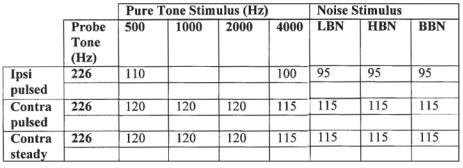
Acoustic Reflex |
Pure Tone Stimulus |
|
|
Activating (Stimulus) |
Frequencies for Contra phone and for Ipsi phone with time multiplexed |
||
Signal |
stimulus. See Table 3. |
|
|
|
FrequencyAccuracy: ±1% |
|
|
|
Total Harmonic Distortion (Acoustically): <2% |
||
|
(Measured 5 dB HL below guaranteed maximum HL) |
||
|
Noise Stimulus |
|
|
|
The uniformity of the spectrum level of acoustic pressure for the noise signal over 20 |
||
|
averages measured acoustically within their respective band limits will be: |
||
|
±10 dB for insert or probe type earphones |
||
|
±5 dB for supra-aural type earphones |
||
|
Noise Band Widths: |
|
|
|
Low Band: 125 -1600 Hz |
||
|
High Band: 1600 - 4000 Hz |
||
|
Broad Band: 125 - 4000 Hz (Relative to level at 1 kHz) |
||
|
Band-edges accurate to within ±15% |
||
|
Roll off rate: |
>12 dB/Octave |
|
Stimulus Level Control
Tone Stimulus: The transfer of reference equivalent threshold values are based on the article; “Reference Threshold Levels For The ER-3A Insert Phone”, by Laura Ann Wilber, Barbara A. Krueger and Mead C. Killion, J. Acoustic Soc. Am. Suppl. 1, Vol. 81 Spring 1987. GSI determined the transfer data from an IEC 711 coupler to an ANSI HA-1 coupler. Using this data, the reference threshold values were determined for both the Ipsi and Contra insert earphones for calibration in an ANSI HA-1 2cc coupler.
Noise Stimulus: The transfer of reference threshold values was done by GSI using the “Threshold Determination Method”. The transfer data from an IEC 711 to an ANSI HA- 1 coupler was determined by GSI.
GSI TympStar Version 1 and Version 2 Service Manual |
2 - 3 |
Chapter 2
Intensity levels are reduced as a function of volume at a rate of 1 dB SPL for each .1 ml. Intensity reduction begins at 1.2 ml.
Table 3: Upper limit of HL range in Reflex Threshold Mode
110 105
Lower limit of HL range for all stimulus signals (35 dB HL).
Hearing Level Increment: |
5.0 dB |
Hearing Level Increment Accuracy: |
±0.5 dB |
Hearing Level Control Linearity: |
±1.0 dB |
2 - 4 |
Grason-Stadler |
|
Specifications |
|
Stimulus |
Signal ON/OFF Ratio: |
>70 dB |
Presentation Control |
OFF mode signal level: |
<20 dB SPL |
|
Signal To Noise Ratio: |
>70 dBA |
|
Measured with disabled probe signal and “A” weighting for noise |
|
|
measurement. |
|
|
Residual noise: |
<25 dBA SPL |
|
(Stimulus Present switch in OFF position) |
|
|
Unwanted Acoustic Probe Signals: |
<60 dBA |
Measured while pump is operating and probe tone is disabled. Measure it with “A” weighted filter in “SLOW” Time mode. The noise in normal operating mode will not effect the immittance measurement accuracy.
Signal separation between Ipsi and Contra channels; all frequencies: >70 dB
|
(Measured at the probes with the “ON” channel set to 90 dB) |
|
Leaked signal: <20 dB SPL |
|
The radiated acoustic noise from the instrument (with reflex stim off) when |
|
measured at 1 meter from the instrument, shall be: <50 dBA |
|
(“A” weighting and “SLOW” averaging) |
Temporal Specifica- |
Steady State Stimulus |
tions of Stimulus |
Initial Delay (elapsed time from present bar activation to 10% stimulus |
Presentation |
amplitude): < 100 msec |
|
Terminal Delay (elapsed time from present bar deactivation to 90% stimulus |
|
amplitude): <100 msec |
|
Rise time: 7.5 ± 2.5 msec |
|
Fall time: 7.5 ± 2.5 msec |
|
Multiplexed Stimulus (Used in Reflex Threshold test mode) |
Period data for frequencies: 250 and 500 Hz:
Period |
124 |
msec |
Stimulus on time |
44 |
msec |
Stimulus off time |
62 |
msec |
Rise and fall time |
18 |
msec |
Period data for all other frequencies: |
||
Period |
115 msec |
|
Stimulus on time |
44 |
msec |
Stimulus off time |
53 |
msec |
Rise and fall time |
18 |
msec |
Temporal Spec. Accuracy: |
±10% or 5 msec, whichever is greater |
|
GSI TympStar Version 1 and Version 2 Service Manual |
2 - 5 |
|
Chapter 2 |
|
Environmental |
The GSI TympStar Version 1 meets ANSI S3.6-1996 Standards for temperature |
|
|
and humidity specifications, and it meets the UL 2601-1, CSA 22.2 and IEC60601- |
|
|
1 standards for safety. |
|
|
Temperature: |
|
|
Storage: -40 degrees C to +75 degrees C |
|
|
Operating: +15 degrees C to +35 degrees C |
|
|
Humidity: 90% at 35 degrees C (non-condensing) |
|
Warm-UpTime |
At room temperature; +15°C to +35°C: |
10 Minutes |
|
At room temperature; below +15°C: |
1 Hour |
2 - 6 |
Grason-Stadler |
|
Specifications |
|
|
Calibration Stability |
All GSITympStar Version 1 specifications are met over the range of specified power |
||
|
line, temperature and humidity variations. |
|
|
|
Power Line: |
|
|
|
Voltage Variation: |
±10% |
|
|
Frequency Variation: |
± 5% |
|
|
Power line short term variation which affects the performance of the instru- |
||
|
ment will turn off all probe and stimulus signals. |
||
|
Power Rating: |
120 |
Watts maximum |
|
Line Voltage Range: |
100 |
VAC to 240 VAC |
|
Power Line Frequency Range: 50 - 60 Hz |
||
|
Temperature Operating Range: +15°C to +35°C |
||
|
Relative Humidity Operating Limit: 90% |
||
|
Guaranteed Operating Elevation: 6000 Ft. (1800m) |
||
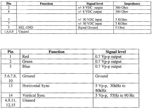
Connectors |
STIMULUS: External Stimulus Input |
|
|
|
(Phone Jack) Peak Voltage: 3 VAC |
|
|
|
Input Impedance: 15,000 Ohms |
|
|
PRESENT: External Present Control Input that turns the stimulus signal ON and OFF (Phone Jack).
Voltage Range: STIM OFF: +5.0 VDC STIM ON: 0.0 v
Input Impedance: 11,000 Ohms
Contra PHONE: Output Voltage: 7 VAC Output Impedance: 2.5 Ohms
Standard 9-pin RS232C serial port for interfacing with outside computer.
RXD
CTS
TXD
RTS
Standard VGAport for external monitor.
GSI TympStar Version 1 and Version 2 Service Manual |
2 - 7 |

Chapter 2
Standard PS-2 keyboard port for external Keyboard.
Standard parallel printer port for external printer.
Electrical |
The following apply to the TympStar system: |
|
|
1) |
Class 1 Medical Equipment |
|
2) |
Type B Medical Equipment |
|
3) |
IPXO ingress of water (ordinary equipment) |
|
4) |
Equipment not suitable for use in the presence of flammable anesthetic |
|
|
mixture with air or with oxygen or nitrous oxide. |
|
5) |
Mode of operation - continuous |
Input Voltage: |
100 – 240 VAC |
Input Frequency: |
50 – 60 Hz |
Input Current: |
3.2 A maximum |
Power Consumption: |
120W maximum |
2 - 8 |
Grason-Stadler |
|
Specifications |
|
SuppliedAccessories |
Contra insert phone |
GSI Part # 8000-0078 |
|
Calibration cavity (V1) |
GSI Part # 2000-1036 |
|
Probe cleaning kit (2 boxes) |
GSI Part # 2000-9610 |
|
Eartips: |
|
|
1 pkg. 8 standard sizes, 4 ea. (Color coded) |
GSI Part # 1700-9660 |
|
1 pkg. 6 special sizes, 2 ea. |
GSI Part # 1700-9670 |
|
1 pkg. 6 screening sizes, 2 ea. |
GSI Part # 1700-9622 |
|
Reference Instruction Manual |
GSI Part # 2000-0100 |
|
Quick User Guide |
GSI Part # 2000-0108 |
|
Printer paper (2 rolls) for orders including printer GSI Part # 1700-9619 |
|
|
Spare set of probe tubing |
GSI Part # 2000-9617 |
|
Probe mount - shoulder |
GSI Part # 1700-9646 |
|
Probe mount - wrist |
GSI Part # 1700-9642 |
|
Probe mount - clothes |
GSI Part # 1700-9608 |
|
Printer paper, adhesive-backed |
|
|
for orders including a printer |
GSI Part # 1770-9643 |
|
GSI TympStar dustcover |
GSI Part # 1700-9618 |
|
Power cord with hospital-grade plug |
GSI Part # 4204-0251 |
|
|
(USA) |
|
Power cord part # varies depending on location |
|
Mechanical |
DIMENSIONS AND WEIGHT |
|
|
W x D x H: 20.38 inches x 15 inches x 12.6 inches (LCD raised) |
|
|
52cm x 38cm x 32cm |
|
|
Height with LCD lowered - 6 inches (15cm) |
|
|
Weight: 16.58 pounds, 7.53 kg |
|
|
Shipping weight: 29.50 pounds, 13.38 kg |
|
Materials of manufacture
Calibration requirements
Top Case, LCD Housing |
|
Front & Rear & Hinges: |
Lexan 500 w/10% Glass & 2% BlowingAgent, |
|
UL 94V0 Rated |
LCD Lense: |
GE HP40S -OR- Duralan II |
Switches: |
Shincor Shin-Etsu/Novacor KE-951 U |
Labels: |
Lexan & Polycarbonate |
Softkey Panel: |
Mylar |
Probe Cord: |
Polyvinyl Chloride (PVC) |
Probe Top & Bottom Housings: |
Cycolac KJW, UL 94V0 Rated |
Probe Tip: |
Polypropolene |
Eartips: |
Kraton 3226 |
Tubing: |
Vinyl and Polyurethane |
GSI recommends quarterly calibration checks for the GSI TympStar along with annual certification. ASHArequires quarterly electro-acoustic calibration checks and annual electro-acoustic calibration. It is good practice to perform daily biologic checks. See Chapter 4: Calibration for complete calibration instructions.
GSI TympStar Version 1 and Version 2 Service Manual |
2 - 9 |

Chapter 2
Version 2 Specifications
Standards |
The GSI TympStar Version 2 meets or exceeds the following standards and speci- |
|
fications for aural acoustic admittance instruments: |
|
IEC 1027 1991-03 |
|
ANSI S3.39-1987 |
|
ANSI S3.6-1996 |
|
ANSI S3.7-1995 |
|
IEC 645-1 1992 |
|
IEC 126-1973 (also BS 6111-1981) |
|
BS ISO 389-2- 1994 |
|
Y2K Compliant |
|
UL 2601-1 Part 1: General Requirements for Safety |
|
CSA C22.2 No. 601.1-M90 (Canada) |
CE Mark per Medical Device Directive (93/42/EEC) European Representative:
Mr. Leo Hoogendoorn Nicolet Biomedical GMBH Saalackerstrasse 8
63801 Kleinostheim, Germany Tel: 011-49-6027-46980
Fax: 011-49-6027-469815
EN60601-1:1990 Safety Requirements for Medical Electrical Equipment
EN60601-1-2 Medical Electrical Equipment Emissions and Immunity
Requirements
This equipment has been tested for radio frequency emissions and has been verified to meet Radiated and Conducted Emissions per EN 55011-1998, Group 1, Class A and per CISPR, Class A.
2 - 10 |
Grason-Stadler |
 Loading...