

Page 1
TV Service Manual
Service
Manual
NUR FÜR INTERNEN GEBRAUCH
FOR INTERNAL USE ONLY
Chassis U1
Vision 2
16-2920 GBH5216
19-2920 GBH5219
22-2920 GBH5222
Zusätzlich erforderliche Unterlagen für den Komplettservice
Additionally required Service Documents for the Complete Service
Sicherheit
Safety
Materialnr./Part No.
720108000001
Materialnummer / Part Number 720100554000
Änderungen vorbehalten / Subject to alteration
TCC 1110 MP • Prepared in Germany
http://www.grundig.com
Page 2

GRUNDIG Service Chassis U1
Es gelten die Vorschriften und Sicherheitshinweise gemäß dem Service Manual "Sicherheit", Materialnummer
720108000001, sowie zusätzlich die eventuell abweichenden, landesspezifischen Vorschriften!
Inhaltsverzeichnis
Allgemeiner Teil
Allgemeine Hinweise .....................................................................1-2
Geräte- und Display-Varianten
Technische Daten
Bedienhinweise
Service- und Sonderfunktionen
.................................. 1-2…1-10
......................................................1-3
..........................................................................1-4
.............................................................................1-6
.....................................................1-8
Seite
Platinenabbildungen
und Schaltpläne
Übersicht .......................................................................................2-1
Chassisplatte YVN190
– Netzteil ...................................................................................... 2-3
– Tuner ..........................................................................................2-3
– Interface HDMI, SCART, VGA ....................................................2-4
– Scaler.........................................................................................2-5
– Verstärker ...................................................................................2-6
Netzteil - Inverter YSY194
Netzteil - Inverter YTF194
Keyboard YAJ192, YSU192, YSW192
.................................. 2-1…2-15
...................................................................2-1
.............................................................2-7
............................................................2-11
.........................................2-15
The regulations and safety instructions shall be valid
as provided by the "Safety" Service Manual, part
number 720108000001, as well as the respective
national deviations.
Table of Contents
General Section
General Notes ...............................................................................1-2
Product and Display Variants
Technical Data
Operating Hints
Service and Special Functions
...............................................................................1-4
.................................. 1-2…1-10
.........................................................1-3
..............................................................................1-6
......................................................1-8
Page
Layout of the PCBs
and Circuit Diagrams
Overview ........................................................................................2-1
Chassis Board YVN190
– Power Supply ............................................................................2-3
– Tuner ..........................................................................................2-3
– Interface HDMI, SCART, VGA ....................................................2-4
– Scaler.........................................................................................2-5
– Amplifier .....................................................................................2-6
Power Supply - Inverter YSY194
Power Supply - Inverter YTF194
Keyboard YAJ192, YSU192, YSW192
......................... 2-1…2-15
.................................................................2-1
...................................................2-7
..................................................2-11
.........................................2-15
Ersatzteillisten ...................................... 3-1…3-7
Allgemeiner Teil
Allgemeine Hinweise
Vor dem Öffnen des Gehäuses den Netzstecker ziehen!
Achtung: ESD-Vorschriften beachten
Leitungsverlegung
Bevor Sie die Leitungen und insbesondere die Masseleitungen lösen, ist
die Leitungs ver legung zu den einzelnen Baugruppen zu beachten.
Nach erfolgter Reparatur ist es notwendig, die Leitungsführung wieder
in den werkseitigen Zustand zu versetzen um evtl. spätere Ausfälle
oder Störungen zu vermeiden.
Durchführen von Messungen
Bei Messungen mit dem Oszilloskop an Halb leitern sollten Sie nur
Tast köpfe mit 10:1 - Tei ler verwen den. Außerdem ist zu beachten, dass
nach vorheriger Messung mit AC-Kopp lung der Koppelkondensator
des Oszillo skops auf geladen sein kann. Durch die Ent ladung über das
Messobjekt können Bau teile beschä digt werden.
Messwerte und Oszillogramme
Bei den in den Schaltplänen und Oszillogrammen angegebenen
Messwerten handelt es sich um Näherungswerte!
Austausch der Chassisplatte
Nach Austausch der Chassisplatte müssen alle Einstellungen im
Service Mode nach Tabelle "Grundeinstellwerte" (Punkt 1 im Kapitel
"Service- und Sonderfunktionen" auf Seite 1-8) eingestellt werden.
Spare Parts Lists .................................. 3-1…3-7
General Section
General Notes
Before opening the cabinet disconnect the mains plug!
Attention: Observe the ESD safety regulations
Wiring
Before disconnecting any leads and especially the earth connecting
leads observe the way they are routed to the individual assemblies.
On completion of the repairs the leads must be laid out as originally
fitted at the factory to avoid later failures or disturbances.
Carrying out Measurements
When making measurements on semi-con duc tors with an oscillo scope,
ensure that the test probe is set to 10:1 dividing factor. If the previous
measurement was made on AC input, please note that the coupling
capacitor in the oscilloscope will be charged. Discharge via the item
being checked can damage the components.
Measured Values and Oscillograms
The measured values given in the circuit diagrams and oscillograms
are approximates!
Change of the Chassis Board
After changing the chassis board all settings in the service mode must
be done according to the table "Basic Settings" (point 1 in chapter
"Service and Special Functions" on page 1-8).
1 - 2
Page 3

GRUNDIG Service Chassis U1
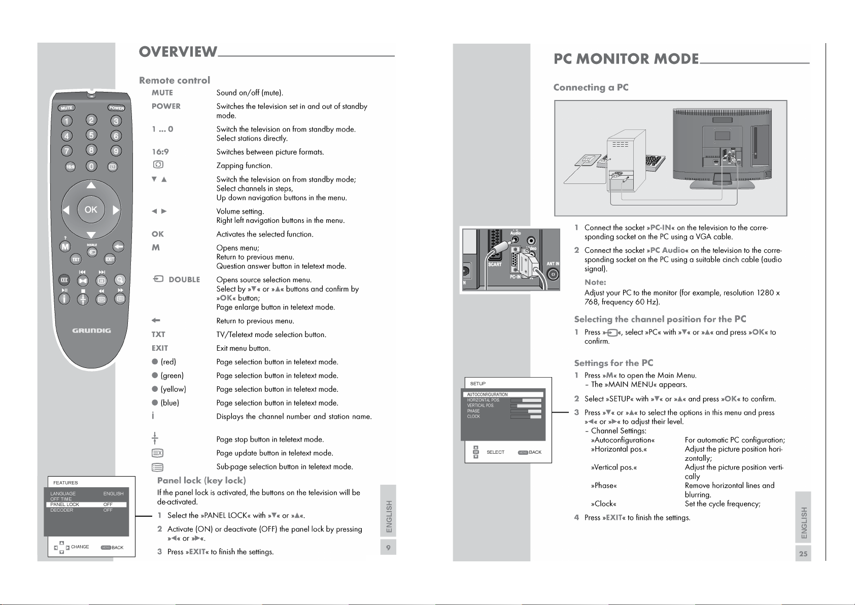
Geräte- und Display-Varianten
Display- und Product Code
Je nach Verfügbarkeit werden
Displays verschiedener Hersteller eingebaut. Dies führt zu
unterschiedlichen Chassis-Bestückungen, sowie zu Änderungen
in der Software. Bei Ersatzteilbestellungen und SoftwareUpdates achten Sie bitte auf das
eingebaute Display, sowie auf den
"Product Code". Angaben dazu
finden Sie auf der Geräterückseite. Sollte in der Ersatzteilliste
des Service Manuals Ihr "Product
Code" oder Ihre Display-Variante
nicht aufgeführt sein, können
Sie eine aktualisierte Version auf
dem GRUNDIG Service-Portal
"http://service.grundig.de" finden.
Überprüfen Sie vor PlatinenTausch, ob die Aufkleber der
Platinen identisch sind (z.B. PCB
Code).
Product Code
Display Type
Display Code
Product and Display Variants
Serialnummer / Serial Number
Chassis
PCB Code
Display- und Product Code
Depending on availability displays
of different manufacturer are built
in. This results in different chassis
mountings as well as a different
software. On spare parts orders
as well as software updates take
care of the fitted display as well as
of the "Product Code". Therefore
you can find information on the
labels on the rear side. If your
"Product Code" or display variant is not mentioned in the spare
parts list of the service manual,
please look for a current version
at the GRUNDIG service portal
"http://service.grundig.de".
Before changing any board please
check whether the labels on the
boards are identical (eg. PCB
Code).
1 - 3
Page 4
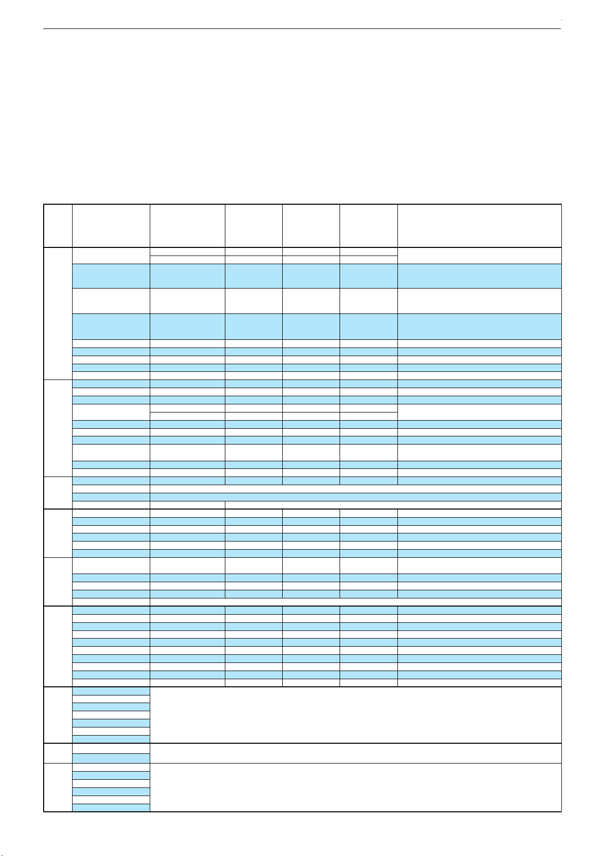
Technische Daten / Technical Data
Vision 2 16-2920 Vision 2 19-2920 Vision 2 22-2920
Order No.
Destination
Approbations
IM-Languages
Remote control
EAN
Color
DISPLAY
Panel
Wide-screen format
Response time
Brightness
Contrast ratio (Panel)
Viewing angle vertical/horizontal, ca. °
Physical display resolution max. pixel
PICTURE
Motion Picture Improvement
Motion Adaptive Deinterlacing
Natural view HD Reference
Full HD
Line Flicker Reduction
Digital Color Transition Improv. (DCTI)
Digital Combfilter
Digital Luminance Transition Improv. (DLTI)
Picture Noise Reduction
Preset picture modes
Aspect ratios (Format switching)
Blackline detection
PIP
Multifold Tuner scan (Mosaic Picture)
PAT: Split screen (PICTURE + TEXT)
PAP: Double Window (PICTURE + PICTURE)
P²AT: Double Window + TXT
POP: PICTURE on PICTURE
Picture freezing
Zoom with point function
Auto 16:9 selection via Scart
Sharpness control
Blue Background
CHASSIS
TV-Chassis
Progressive
Tuner
Scaler
Keyboard
ELECTRONIC
Stand by indicator
EPG (Electronic Programme Guide)
Easy Dialog
Megalogic
Manual & autom. labeling of prog.
Programmable off timer
Programmable on timer
Intelligent channel search (Zapping funct.)
Programme Edit
Intelligent Programme Switch
Programme memory TV/AV (opt.)
Teletext/Fasttext/Toptext
Teletext options
Childlock
Menue languages OSD
OSD-style
SWAP (Recall function)
Service mode
Game mode
Hotel mode
TUNING
Autom. Tuning System with country selection
Frequency Based Auto Search
Automatic Micro-search
Automatic Programming
Manual fine tuning
Direct channel selection
Direct frequency selection
PAL/SECAM/BG/DK/I/L'/L
NTSC-Playback via Scart (3,58/4,43)
Cable TV / Hyperband (S1-S41)
GBH5216
Region 4
GBH5219
Region 4
GBH5222
Region 4
CE
GB,P,GR,AR,RO
CE
GB,P,GR,AR,RO
RUS, SLO
RC 23
RUS, SLO
RC 23
CE
GB,P,GR,AR,RO
RUS, SLO
RC 23
40 13833-61920 8
glossy black
40 13833-61889 8
glossy black
16" / 40cm 19" / 49cm
Ye s
ca. 8ms
Ye s
ca. 5ms
ca. 250cd/m2
ca. 500:1
ca. 250cd/m2
ca. 1.000:1
40 13833-61890 4
glossy black
22" / 56cm
Ye s
ca. 5ms
ca. 250cd/m2
ca. 800:1
65 vertical / 90 horizontal
WXGA 1366 x 768
80/80 80/80
WXGA 1366 x 768
2D DeInterlacer
2D DeInterlacer
85/85 75/85
WXGA 1366 x 768
2D DeInterlacer
2D
2D
user, natural, rich, soft
Auto (WSS), 4:3 / 14:9 / 16:9 / Panorama / Cinema Zoom / Sky Top
user, natural, rich, soft
2D
user, natural, rich, soft
U1 U1
PLL frequency synthesizer tuning
PLL frequency synthesizer tuning
MSTAR Maria 5
4 Volume/Programm, ± keys, stand-by
MSTAR Maria 5
4 Volume/Programm, ± keys, stand-by
U1
PLL frequency synthesizer tuning
MSTAR Maria 5
4 Volume/Programm, ± keys, stand-by
blue LED blue LED
sleep timer function
sleep timer function
blue LED
sleep timer function
100 Analog / AV
100 Analog / AV
/ /
8 pages
/ /
8 pages
23 languages, D, GB, F, I, E, P, NL, DK, S, FIN, N, TR, GR, PL, CZ, SK, SLO, H, RUS, HR, RO, BG, SER
100 Analog / AV
/ /
8 pages
OEM-style
OEM-style
Simple hotel mode possible via service adjustment Simple hotel mode possible via service adjustment
full automatic sorting
full automatic sorting
OEM-style
Simple hotel mode possible via service adjustment
full automatic sorting
Chassis U1GRUNDIG Service
1 - 4
Page 5
Vision 2 16-2920 Vision 2 19-2920 Vision 2 22-2920
AUDIO
Mono/Stereo/Nicam
AV Stereo
Loudspeaker
SRS
Virtual Dolby
Magic Fidelity Sound System
Sound Projector
Matched Sound Delay (Lip synchronous)
Subwoofer
Dynamic Bass
DSP (Digital Sound Processor)
Balance Adjustment
AVL (Audio Volume Level)
PIP listening via Headphone.jack
Equalizer
Space Sound Effect
Audio mode
Audio amplifier
DVB reception
DVB-S
FRONT PANEL CONNECTIONS
HDMI
Headphones
Cinch-AV socket
S-Video
POWER SUPPLY / CABINET
Power voltage
Range of regulation
Power switch
Integrated supply
Plug-in AC adaptor
Power consumption
Cabinet (WxHxD, cm)
Cabinet with stand (WxHxD, cm)
Weight
REAR PANEL CONNECTIONS
Euro-AV-Socket AV1
Euro-AV Socket AV2
Euro-AV Socket AV3
S-Video
Camera-AV
Wireless
YUV input / progressive
PC-input
PC-Audio in
DVI
HDMI
HD ready including HDCP
Common Interface
Headphones
Digital Audio out coaxial (SPDIF)
Video out
Audio out
USB
Antenna for terrestrial reception
DC-connector
Power supply plug
SUPPLIED ACCESSORIES
Remote control (incl. battery)
Power cord
Cables
Instruction manual
Circuit diagram
Wall fixture
Warning sticker in rear panel
Stand
Warranty info
Cleaning tissue
/ /
/ /
2 wide band at the front side
2 wide band at the front side
/ /
2 wide band at the front side
2x 2W (RMS) 2x 2,5W (RMS)
2x 3W (RMS)
230V, 50Hz; in accordance to IEC 65 230V, 50Hz; in accordance to IEC 65
140V - 265V
Tact switch
140V - 265V
230V, 50Hz; in accordance to IEC 65
140V - 265V
24W, standby <1W
in accordance to IEC 62087-2002
38,7x27,9x6,5cm
38,7x31,1x13,5cm
ca. 2,8kg
30W, standby <1W
in accordance to IEC 62087-2002
45,8x31,5x6,5cm
45,8x34,3x16,5cm
ca. 3,5kg
Full wired Full wired
via Scart
3x Cinch socket in
via Scart
3x Cinch socket in
45W, standby <1W
in accordance to IEC 62087-2002
52,5x46,3x6,5cm
52,5x46,3x16,5cm with stand
ca. 4,5kg
Full wired
via Scart
3x Cinch socket in
via VGA
via VGA
WXGA
WXGA
1x
1x
via HDMI
via HDMI
via VGA
WXGA
1x
via HDMI
3.5mm jack
3.5mm jack
1 x Coaxial-socket for TV-tuner-in
according to DIN 45325
1 x Coaxial-socket for TV-tuner-in
according to DIN 45325
12V DC (11 - 14,5V, current consumption ca. 4 A)12V DC (11 - 14,5V, current consumption ca. 4 A)
3.5mm jack
1 x Coaxial-socket for TV-tuner-in
according to DIN 45325
-
RC 23 incl. 2x Battery AAA size RC 23 incl. 2x Battery AAA size
non grounded
non grounded
Prepared for VESA standard adaptor 100 x 100Prepared for VESA standard adaptor 100 x 100
RC 23 incl. 2x Battery AAA size
non grounded
Prepared for VESA standard adaptor 100 x 100
Chassis T6GRUNDIG Service
1 - 5
Chassis U1GRUNDIG Service
1 - 5
Page 6
Chassis TD / TEGRUNDIG Service
1 - 6
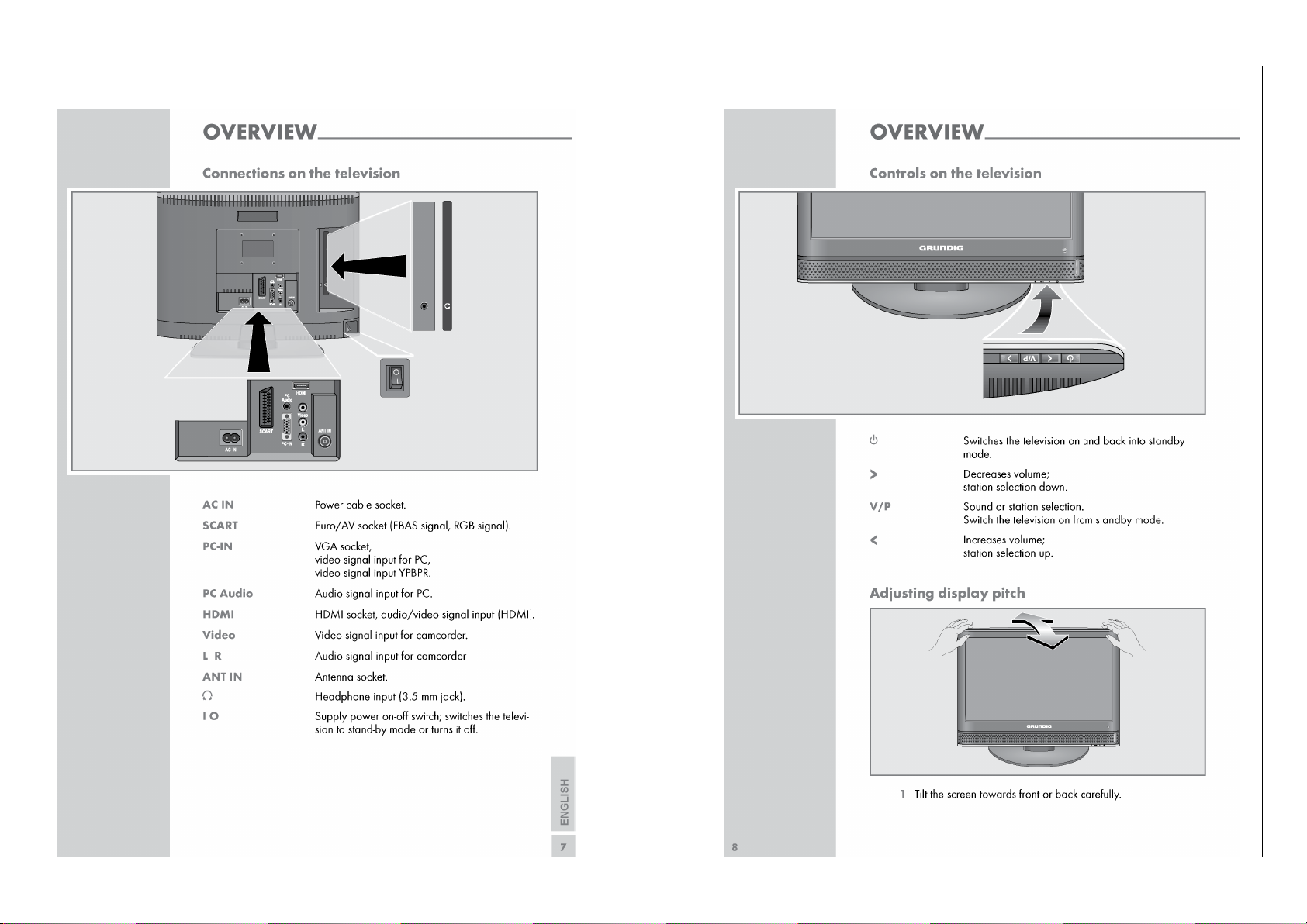
Operating Hints This chapter contains excerpts from the operating instructions. For further particulars please refer to the appropriate user instructions which can be downloaded from www.grundig.com.
Chassis U1GRUNDIG Service
1 - 6
Page 7
Chassis TD / TEGRUNDIG Service
1 - 7
Chassis T8 / T9GRUNDIG Service
1 - 7
Chassis T8 / T9GRUNDIG Service
1 - 7
Chassis T8 / T9GRUNDIG Service
1 - 7
Chassis U1GRUNDIG Service
1 - 7
Page 8
Service- und Sonderfunktionen
Tastenfunktionen
MENU
Aufrufen des Dialog Centers / Menü verlassen
3333 4444,
0…9
Menü-Zeile (Menüpunkt) wählen
1111 22
22
Aufrufen des Menüs, Wert ändern
BACK
Menü verlassen
EXIT
Beenden des Service Mode
Service-Mode aktivieren
– Taste "
MENU
" (INFO) drücken.
– Zahlenfolge "
8500
" oder "
9301
" eingeben.
Service-Mode beenden
– Taste "
EXIT
" drücken.
1. Grundeinstellwerte
Service and Special Functions
Functions of the buttons
MENU
Call up the Dialog Center / close down the Menu
3333 4444,
0…9
Call up the dialogue line (point of menu)
1111 22
22
Call up the Menus, Changing the settings
BACK
Close down the Menu
EXIT
Exit the Service Mode
Calling up the Service Mode
– Press button "
MENU
" (MAIN MENU).
– Enter the code number "
8500
" or "
9301
".
Exit the Service Mode
– Press button "
EXIT
".
1. Basic Settings
Menüpunkt
Point of Menu
3333 44
44
0…9
Einstellung
Adjustment
1111 22
22
Vision 2
16-2920
Vision 2
19-2920
Vision 2
22-2290
Hinweis
Hint
1. OPTIONS I
2. OPTIONS II3. VIDEO4. AUDIO5. TUNING6. SOURCE7. PRESET
8.
NVM
EDIT
9. INFO
Menü
Menu
33
33
44
44
0…9
1. STANDBY
CUSTOMER
FACTORYXX
X
2. PLUG N PLAY
3. TXT TYPE
ON/OFF
DEFAULT, FASTEXT,
TOPTEXT, FASTEXT
TOPTEXT, NO
4. TXT TABLE
5. PROTECTION
AUTO, WEST, EAST,
CYRILLIC, GREEK,
ARABIC, PERSIAN
ON/OFF
OFF
FASTEXT
OFF
FASTEXT
AUTO
ON
AUTO
ON
OFF
FASTEXT
ATS Reset (ON)
Netz ein –> Automatischer Sendersuchlauf
Power on –> automatic programme search
AUTO
ON
6. POWER UP
7. RECALL LAST AV
LAST STATE, STANDBY
ON/OFF
8. MONITOR FEATURES
9. KEYPAD TYPE
YES/NO
1 KEY, 4 KEY, 7 KEY
1. LOGO
2. OSD LANGUAGE
GRUNDIG
GROUP A / B
3. OSD SIZE
4. CURSER KEYS
X1/X2
VOL-PROG FUNCTION
LAST STATE
ON
LAST STATE
ON
YES
4 KEY
YES
4 KEY
LAST STATE
ON
YES
4 KEY
X
GROUP A
X
GROUP AX1XX1XXGROUP AX1X
5. GAME MODE
ONLY CURSER
ON/OFF
6. CLOCK DISPLAY
7. HOTEL HEADPHONE
ON/OFF
ON/OFF
8. HOTEL TV
9. VOLUME LIMIT
ON (SIMPLE)/
LOCATEL/OFF
0…50
0. HDMI DDC UPDATE
1. BLUEBACK
ON/OFF
ON/OFF
OFF
OFF
OFF
OFF
OFF
OFF
OFF
OFF
OFF
OFF
16
OFF
16
OFFONOFF
ON
OFF
16
siehe Punkt 8 / see point 8
siehe Punkt 8 / see point 8
OFF
ON
2. WHITE BALANCE
3. ADC ADJUST
siehe Punkt 3
siehe Punkt 4
DIMMING
1. BG
0…255
EU, NEW, AUS, OFF
2. DK
3. I
ON/OFF
ON/OFF
4. L
5. AUDIO POWER
ON/OFF
2W
Maximale Intensität der Hintergrundbeleuchtung einstellen / Set intensity of backlight to maximum
EUEUEUONONONON
ON2WON
2.5W
ON
ON
ON
3W
6. AUTO MUTE
1. ATS SORTING
ON/OFF
ON/OFF
2. AGC VHF
3. AGC UHF
0…31
0…31
4. AGC L PRIME
5. TUNER TYPE
0…31
Eingebauten Tuner wählen / Select used tuner
1. ANALOG
2. DIGITAL
YES/NO
EUROPE, UK, NO
ONONON
ON
141414
14
ON
ON
Programmsortierung bei Programmsuchlauf
Programme sorting at autoprogramme operation
14141414YESNOYESNO14
YES
NO
3. DVD
4. USB
YES/NO
YES/NO
5. SCART
6. SCART-SVHS
YES/NO
YES/NO
7. AV
8. HDMI
YES/NO
YES/NO
9. YPBPR
0. PC
YES/NO
YES/NONONONONO
YES
YES
YES
YES
NO
NO
YES
YES
YES
YES
YES
YES
YES
YES
YES
YES
YES
YES
YES
YES
1. USER
2. PROGRAMME TABLE
Achtung: Kunden- und Gerätespezifische Einstellwerte werden gelöscht und mit Grundwerten geladen.
Attention: Erases the customer and set specific values and loads the default values.
3. PC MODES
4. WHITE BALANCE
5. ADC
6. SERVICE
7. ALL
NVM ADDR. HEX
siehe Punkt 9
see point 9
NVM DATA HEX
EEPROM
Prüft über das Bus-System die Kommunikation mit den jeweiligen Komponenten.
Checks the communication to the components via the bus system.
TUNER
IF
AUDIO
DTV
HDCP KEY
Chassis L5C-26"…32"GRUNDIG Service
1 - 8
Chassis SH/SMGRUNDIG Service
1 - 8
Chassis U1GRUNDIG Service
1 - 8
Page 9
Chassis SH/SMGRUNDIG Service
1 - 9
Menüpunkt
Point of Menu
3333 44
44
0…9
Einstellung
Adjustment
1111 22
22
Vision 2
16-2920
Vision 2
19-2920
Vision 2
22-2290
Hinweis
Hint
0. USER DEFAULTS
Menü
Menu
33
33
44
44
0…9
DEFAULT SETTINGS 1
1. VOLUME
16
Diese Grundeinstellwerte wirken sich nur aus wenn Sie
die Grundwerte USER laden.
The user default settings are only activ when you load the
presets USER.
(siehe / see 7. PRESET –> 1. USER).
2. BASS
3. TREBLE
4. BALANCE
5. SOUND MODE
6. RED
7. GREEN
8. BLUE
9. ACTIVE ANTENNA
15
15
25
NORMAL
128
128
128
OFF
DEFAULT SETTINGS 2
1. IF SOURCE IS
2. PICTURE MODE
3. COLOUR TEMP.
4. DNR
DEFAULT SETTINGS 3
5. CCE
siehe Punkt 2 / see point 2 (Default Settings 3)
ANALOG
RICH
NORMAL
LOW
ON
3. Weißabgleich (WHITE BALANCE)
Für alle Eingangssignale sind die Farbtemperaturen NORMAL,
WARM und COOL getrennt einstellbar.
– Weiss-Testbild am gewünschten Eingang einspeisen und diese
Quelle mit den Tasten "
AV" 3333 4444 anwählen.
–Taste "
MENU
" (INFO) drücken und Zahlenfolge "
8500
" oder "
9301
"
eingeben.
– Grundwerte laden: Tasten
7, 4
und
2222 nacheinander drücken und
mit Taste "
BACK"
beenden.
– Tasten 3 und 2 nacheinander drücken.
– Signalquelle "SOURCE TYPE" mit den Tasten
1111 2222 wählen.
–Taste 2 drücken und mit den Tasten
1111 2222 die gewünschte Farb-
temperatur wählen.
– Mit den Tasten 3 "R GAIN", 4 "G GAIN" und 5 "B GAIN" nachein-
ander anwählen und mit den Tasten
1111 2222 nach Testbild abglei-
chen.
4. Analog-Digital-Wandler (ADC ADJUST)
Für die Eingangssignale SCART-RGB, PC und YPBPR ist der Analog-Digital-Wandler getrennt einstellbar.
– Grautreppen-Testbild am gewünschten Eingang einspeisen und
diese Quelle mit den Tasten "
AV" 3333 4444 anwählen.
–Taste "
MENU
" (INFO) drücken und Zahlenfolge "
8500
" oder "
9301
"
eingeben.
– Tasten
3
und 3 nacheinander drücken.
– Signalquelle "ADC SOURCE" mit den Tasten
1111 2222 wählen.
–Taste 2 drücken und mit der Taste
2222 den automatischen Abgleich
starten.
– Gegebenenfalls das Grautreppen-Testbild unbunt nachgleichen.
Dazu mit den Tasten 3…8 die Menüzeilen "RGB GAIN" und "RGB
OFFSET" anwählen und jeweils mit den Tasten
1111 2222 abgleichen.
5. Austausch der Hauptplatte oder des IC201
Nach dem Austausch der Hauptplatte oder des IC201 sind die
Grundeinstellwerte im Service Mode entsprechend der Tabelle einzustellen.
6. Geräte-Software
Die Software-Versionsnummer der Gerätesoftware wird unten im
Service-Menü angezeigt, z.B.:
SW VERSION : SSH19W-SS5-T46-S1 GRUNDIG
3. White Balance
The colour temperatures NORMAL, WARM and COOL are adjustable for all input signals.
– Fit in a white test pattern at the desired input and select it with
buttons "
AV" 3333 4444.
– Press button "
MENU
" (MAIN MENU) and enter the code number
"
8500
" or "
9301
".
– Load Presets: Press the buttons
7, 4
and
2222 step by step and con-
firm it with button "
BACK
".
– Press the buttons 3 and 2 step by step.
– Select SOURCE TYPE with buttons
1111 2222.
– Press button 2 and adjust the white balance with buttons
1111 2222.
– Select with buttons
3
"R GAIN", 4 "G GAIN" und 5 "B GAIN" step
by step and adjust with buttons
1111 2222 according to test pattern.
4. Analogue Digital Converter (ADC ADJUST)
The analogue digital converter is seperately adjustable for the input
signals SCART-RGB, PC and YPBPR.
– Fit in a grey scale test pattern at the desired input and select it
with buttons "AV"
3333 4444.
– Press button "
MENU
" (MAIN MENU) and enter the code number
"
8500
" or "
9301
".
– Press the buttons
3
and 3 step by step.
– Select "ADC SOURCE" with buttons
1111 2222.
– Press button 2 and
2222 to start the automatic adjustment.
– If necessary, readjust to an achromatic grey scale test pattern.
Select the menu lines "RGB GAIN" and "RGB OFFSET" with buttons
3…8
and adjust with buttons
1111 2222.
5. Change of the Main Board or IC201
After changing the Main Board or IC201 all basic settings in the service mode must be done according to the table.
6. Software
The software version number of the TV software is shown on the lower part of the service menu, e.g.:
SW VERSION : SSH19W-SS5-T46-S1 GRUNDIG
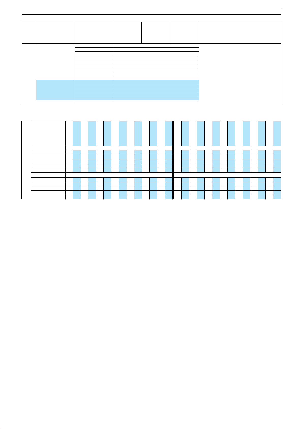
DEFAULT SETTINGS 3
1. SOURCE TYPE
TUNER 50HZ
CVBS 50HZ
SVHS 50HZ
RGB 50HZ
HDMI SD
2. IF PICT. MODE IS
3. BRIGHTNESS
USER
130 128 118 118 110
4. CONTRAST
5. COLOUR
124
128
6. TINT
7. SHARPNESS
50
28
124
128
122
129
502850
28
116
129
126
128
502850
28
2. IF PICT. MODE IS NATURAL
3. BRIGHTNESS
4. CONTRAST
130
124
5. COLOUR
6. TINT
128
50
7. SHARPNESS 28
128
124
118
122
118
116
110
126
12850129
50
28 28
12950128
50
28 28
YPBPR SD
PC
114 112
TUNER 60 HZ
CVBS 60HZ
130 128
114
128
101
128
502850
28
124
128
124
128
502850
28
SVHS 60HZ
RGB 60HZ
118 118
HDMI/DVI
HDMI HD
110 110
122
129
116
129
502850
28
126
128
126
128
502850
28
114
114
112
101
130
124
128
124
12850128
50
28 28
12850128
50
28 28
118
122
118
116
110
126
110
126
12950129
50
28 28
12850128
50
28 28
YPBPR HD
114
TUNER 50HZ
CVBS 50HZ
SOFT
132 130
114
128
50
28
96
12096120
501650
16
SVHS 50HZ
RGB 50HZ
120 120
HDMI SD
YPBPR SD
123 123
96
12196121
501650
16
96
12096120
501650
16
114
114
RICH
126
142
124
138
128
50
28
16050160
50
45 45
114
140
114
130
126
142
116
128
16150161
50
45 45
16050161
50
61 61
PC
TUNER 60 HZ
115 132
CVBS 60HZ
SVHS 60HZ
130 120
88
12096120
501650
16
96
12096121
501650
16
RGB 60HZ
HDMI/DVI
120 123
HDMI HD
YPBPR HD
123 123
96
12196120
501650
16
96
12096120
501650
16
120
106
126
142
124
138
114
140
16050160
50
61 45
16050161
50
45 45
114
130
126
142
126
142
116
128
16150160
50
45 61
16050161
50
61 61
2. Default Settings 3 2. Default Settings 3
Chassis U1GRUNDIG Service
1 - 9
Page 10

Chassis SH/SMGRUNDIG Service
1 - 10
7. Programmsuchlauf
– Taste "AV" drücken.
– "TV" mit den Tasten
3333 4444
anwählen und mit der Taste "OK" bestä-
tigen.
– Taste "
MENU
" (INFO) drücken.
– "SUCHEN / ABSTIMMUNG" mit den Tasten
3333 4444
anwählen und
mit der Taste "OK" bestätigen.
– "PROGRAMMSUCHLAUF" mit den Tasten
3333 4444
anwählen und mit
der Taste "OK" bestätigen.
– Gewünschtes Land mit den Tasten
3333 4444
1111 2222 auswählen und mit
der Taste "OK" bestätigen.
Das automatische Sendersuchsystem stoppt bei jedem empfangswürdigen Sender (AFC und Koinzidenz) und speichert automatisch die entsprechenden Senderdaten mit dem jeweiligen
Standard. Danach wird der Suchlauf fortgesetzt.
– Zum Abbrechen des Suchlaufes die Taste "
MENU
" (analog) /
"
EXIT
" (digital) drücken.
8. Hotel-Mode
Bei aktivierter Funktion ist die maximale Lautstärke begrenzt und
Programmtabelle sowie Installation sind im MAIN MENU nicht mehr
anwählbar.
Aufruf:
MENU
–> "
8500
" oder "
9301
" –>
2
"OPTION II" –>
1111 2222 –>
8
"HOTEL TV" –>
1111 2222 "ON".
Hinweis zu Geräten mit Digital-TV: Wenn "LOCATEL" angewählt
wurde ist kein Digital-TV-Empfang mehr möglich.
Abhilfe:
MENU
–> "
8500
" oder "
9301
" –>
6
"SOURCE" –>
2
"DIGI-
TAL" –>
1111 2222 "EUROPE".
Maximale Lautstärke:
MENU
–> "
8500
" oder "
9301
" –>
2
"OP-
TIONII" –>
1111 2222 –> 9 "VOLUME LIMIT" –>
1111 2222 Wert 0…63.
9. NVM EDIT
Diese Funktion ist ausschließlich für die Entwicklung und darf nur
nach besonderer Aufforderung verwendet werden. Bei falschen Eingaben sind die Gerätefunktionen nicht mehr gewährleistet.
7. Programme Search
– Press button "AV".
– Select "TV" with the buttons
3333 4444 and confirm with button "OK".
– Press button "
MENU
" (MAIN MENU).
– Select "SETUP" with the buttons
3333 44
44
and confirm with button
"OK".
– Select "AUTOPROGRAM" with the buttons
3333 4444
and confirm with
button "
OK
".
– Select the required Country with the buttons
3333 4444
1111 2222 and confirm
with button "OK".
The auto programme system stops at every station of acceptable
reception quality (AFC and coincidence) and stores the station
data and the respective standard automatically. The system then
continues searching.
– Pressing the button "
MENU
" (analogue) / "
EXIT
" (digital) button
stops the programme search.
8. Hotel Mode
Maximum volume is limited and there is no access to "Preset List"
and "Setup" of the main menu at activated hotel mode.
Call up:
MENU
–> "
8500
" or "
9301
" –>
2
"OPTION II" –>
1111 2222 –>
8
"HOTEL TV" –>
1111 2222 "ON".
Note to sets with Digital TV: After call up "LOCATEL" is Digital TV
deactivated.
Resolution:
MENU
–> "
8500
" or "
9301
" –>
6
"SOURCE" –>
2
"DIGI-
TAL" –>
1111 2222 "EUROPE".
Maximum volume:
MENU
–> "
8500
" or "
9301
" –>
2
"OPTION II" –>
11112222 –> 9 "VOLUME LIMIT" –>
1111 2222 Wert 0…63.
9. NVM EDIT
This function is only for development and is only allowed to use by
special demand. Any incorrect settings may cause a defectiv set.
Chassis U1GRUNDIG Service
1 - 10
Page 11

GRUNDIG Service Chassis U1
Platinenabbildungen und Schaltpläne / Layout of PCBs and Circuit Diagrams
Übersicht / Overview
HDMI IN
KEY/IR CONTROL
DEBUG PORT
FLASH 2M
2.5V
LINEAR
PWM
3.3V
LINEAR
E2PROM
SOUND MUX
POWER AMP
TUNER & IF
PC AUDIO IN
AMP OUT
VGA
CVBS
INVERTER
+12V
POWER
+5.0V
LVDS PANEL I/FCN1
TTL PANEL I/FCN2
SCART IN
3.3 OR 5V
SOFT-START
MST7266A
128PIN
3.3 OR 5V
VDDP
I2C BUS
VDDC
Chassisplatte / Chassis Board YVN190
POS. X Y POS. X Y POS. X Y POS. X Y POS. X Y POS. X Y POS. X Y POS. X Y
C100 124 110
C101 124 112
C102 125 115
C103 139 100
C104 126 110
C105 127 114
C106 130 111
C107 103 101
C108 132 96
C109 127 119
C110 127 117
C111 127 113
C112 146 96
C113 147 102
C114 128 119
C116 143 96
C117 139 96
C118 134 96
C119 122 96
C121 123 96
C122 127 96
C123 125 96
C150 119 111
C152 130 110
C200 48 37
C201 52 37
C202 55 47
C203 45 44
C204 42 74
C205 55 44
C206 51 44
C207 57 67
C208 19 74
C209 41 44
C210 47 44
C211 57 60
C212 57 59
C213 57 57
C214 48 74
C215 51 74
C216 32 71
C219 32 55
C221 43 77
C223 34 84
C224 43 44
C227 49 74
C228 40 74
C229 24 74
C230 57 71
C300 25 44
C301 25 38
C302 44 13
C303 22 119
C304 53 7
C305 38 13
C306 32 40
C307 7 124
C308 18 83
C309 29 37
C310 19 100
C311 19 102
C312 23 78
C313 11 14
C314 25 79
C315 10 29
C316 7 126
C317 22 126
C318 25 118
C331 47 13
C332 25 46
C333 25 34
C335 37 13
C336 34 8
C400 102 19
C401 100 19
C402 78 37
C403 72 16
C404 110 21
C406 106 19
C407 107 19
C408 57 66
C409 57 63
C410 70 22
C411 112 21
C412 113 19
C414 70 24
C415 125 19
C416 117 19
C417 118 19
C418 70 30
C419 80 14
C422 70 21
C427 80 11
C428 83 11
C429 76 33
C430 74 21
C432 57 64
C433 115 41
C434 141 19
C435 111 41
C436 75 21
C439 72 21
C500 34 99
C501 45 115
C502 112 113
C503 34 97
C504 41 99
C505 44 115
C506 28 113
C507 65 95
C508 67 115
C509 30 115
C510 36 117
C511 36 119
C512 46 99
C513 31 99
C514 48 114
C515 137 58
C516 121 58
C517 96 113
C518 44 99
C519 122 58
C520 42 99
C521 66 115
C523 135 58
C524 42 115
C525 103 34
C526 28 102
C527 33 115
C528 106 42
C529 33 97
C530 33 118
C531 23 101
C532 39 99
C533 19 111
C534 40 115
C535 52 97
C536 30 99
C537 31 115
C538 37 99
C539 43 121
C540 49 99
C541 60 110
C542 51 123
C543 67 113
C545 74 9
C546 51 125
C547 104 111
C548 104 113
C549 48 99
C550 21 101
C551 51 127
C552 67 94
C553 108 40
C554 103 30
C555 48 116
C558 50 88
C559 56 78
C560 47 84
C561 74 6
C562 76 6
C563 79 6
C564 79 9
C565 76 9
C566 109 58
C567 109 60
C570 36 114
C590 38 115
D100 139 108
D101 103 104
D201 27 74
D400 127 27
D401 147 20
D402 129 27
D403 132 27
D404 77 43
D405 86 53
D406 86 50
D408 87 47
D409 87 46
D410 87 43
D500 60 120
D501 60 124
IC101 126 103
IC200 44 59
IC201 30 83
IC202 40 80
IC203 21 74
IC300 8 118
IC302 22 83
IC303 27 123
IC400 81 37
IC401 141 23
IC402 74 27
IC501 78 112
IC503 51 83
IC504 40 107
IC505 23 107
IC506 78 94
L100 122 112
L101 127 115
L102 152 96
L103 132 98
L104 109 97
L205 43 74
L206 57 44
L207 53 44
L209 59 68
L211 57 47
L212 42 44
L213 34 81
L215 39 44
L216 45 79
L300 26 31
L302 50 10
L303 35 6
L304 12 12
L305 10 31
L400 81 11
L401 68 29
L402 124 21
L403 82 8
L404 128 19
L405 82 7
L500 60 117
L501 145 61
L502 96 90
L503 112 119
L504 95 118
L505 143 61
L506 19 109
L507 96 124
L508 95 106
L509 142 61
L510 48 88
L511 147 61
L512 106 113
L513 102 112
R100 133 102
R101 119 113
R102 139 106
R103 108 108
R104 132 102
R105 125 116
R107 127 110
R108 107 108
R109 127 111
R111 134 97
R112 137 96
R113 101 97
R114 141 96
R115 154 63
R116 106 97
R117 104 63
R119 129 96
R120 130 96
R121 120 96
R137 112 108
R138 121 109
R139 110 108
R189 126 96
R200 50 44
R201 57 55
R202 21 71
R203 48 44
R205 42 85
R206 32 68
R207 32 69
R208 30 78
R209 30 77
R210 33 77
R211 33 78
R220 39 85
R222 43 79
R300 53 8
R301 53 10
R302 20 117
R303 24 112
R304 25 36
R305 36 44
R306 29 41
R307 34 40
R308 35 9
R309 41 13
R310 39 13
R311 32 41
R312 29 6
R313 33 48
R314 29 9
R315 53 11
R316 53 12
R317 11 21
R318 11 19
R319 11 18
R320 11 124
R321 14 124
R324 22 117
R325 28 127
R327 30 122
R400 96 19
R401 99 19
R402 98 19
R403 81 43
R404 82 43
R405 109 19
R406 83 43
R407 77 16
R408 110 19
R409 86 34
R410 78 14
R411 104 19
R412 72 33
R413 129 20
R414 114 19
R415 85 39
R416 115 19
R417 122 19
R418 73 14
R419 124 19
R420 120 19
R421 87 44
R422 91 40
R423 121 19
R424 75 16
R425 83 14
R426 71 14
R427 103 19
R431 77 11
R432 114 41
R433 74 33
R434 112 41
R435 117 58
R436 115 58
R437 116 58
R438 74 27
R439 129 25
R440 119 58
R441 75 27
R442 135 23
R443 135 24
R444 139 27
R445 127 25
R446 72 27
R447 132 25
R448 135 21
R449 82 47
R450 82 46
R451 84 47
R452 84 46
R457 111 19
R500 35 97
R501 47 118
R502 38 119
R503 138 58
R504 124 58
R505 43 96
R506 103 32
R507 52 103
R508 52 101
R509 67 110
R510 36 115
R511 46 96
R512 106 40
R513 49 96
R514 48 118
R515 50 114
R516 66 103
R517 33 99
R518 48 125
R519 34 115
R521 67 92
R522 105 116
R523 107 116
R524 51 99
R525 102 114
R526 102 116
R527 63 102
R528 66 102
R529 63 97
R530 63 95
R531 46 86
R532 57 80
R533 55 80
R534 46 88
R535 48 124
R536 78 9
R537 55 117
R538 54 120
R539 23 98
R540 21 98
R541 56 115
R542 55 120
R543 78 6
R544 31 117
R545 30 97
R546 110 60
R547 111 58
R548 110 58
R549 63 96
R550 61 102
RP200 27 50
RP201 27 53
RP202 27 57
RP203 27 62
RP204 27 66
RP205 46 74
RP207 38 74
S1 147 45
S2 147 54
S100 13 6
S101 151 24
S300 20 60
S301 6 21
S302 43 6
S400 116 9
S401 9 61
S402 132 33
S403 93 50
S501 124 49
S503 108 33
S506 149 48
S507 104 123
S900 5 88
S901 5 5
S902 155 5
S903 155 128
S905 35 128
SAW100 113 101
SAW101 113 105
T103 117 109
T300 25 41
T301 29 44
T302 31 7
T303 64 100
T305 33 37
T306 33 44
T308 22 122
T309 23 114
T400 86 36
T401 88 40
T402 132 20
T403 75 14
T505 54 124
TU100 127 80
X101 134 111
X200 50 41
2 - 1
Page 12

Chassisplatte / Chassis Board YVN190
Ansicht von der Bestückungsseite
View of Component Side
2 - 2
S300
LVDS
29
IC303
C533
L506
C311
C310
C308
C208
31
30
FID3
C317
T308
C303
R324
R302
T309
1
C550
R540
R327
C318
C509
C506
R303
32
IC505
IC504
C526
C531
R539
R502
C530
C510C511
R544
R510
C590
C570
R519
C537
C527
1
C513
C500
C536
C538
C529 R517
R545
R500
C503
24
C532
C539
C534
C504
C524
C505
C520
R505 R511
R518
R535
R501
C555
C501
C514
C518
C512
C549
R513
S905
R325
IC302
L510
1
C223
IC201
L213
R208
R211
C314
C312
D201
C229
IC203
R202
RP204
RP203
RP202
RP201
1
RP200
C332
C300
R306
T300
C301
R304
C333
L300
IC202
R209
R210
C216
R207
65
R206
C219
102
R313
R305
T301
T306
R311
R307
C306
C309
T305
PWR
9
C335
R308
1
C336
T302
R312 R3 14
L303
R534
R531
R205
R220
1
C560
L216
C221 R222
IC503
L205
C204
C228
RP207
64
IC200
C214
RP205
6
103
C305
C210
L212
C224
C203
C209
L215
X200
C200 C201
C302 C331
R310
R309
10
D501
C551
C546
T505
C542
R538
R514
R537 R542
D500
R541
R515
17
R507
16
R508
R524
C540
C535
23
C558
R533
R532
C559
1
C215
C227
39
C230
38
C207
C408
C432
C409
C211
C212
C213
R201
1
128
R203
1
L211
C202
R200
C206
C205
L207
L206
GRUNDIG ELK.
R316
R315
L302
R301
YVN190R-2
R300
C304
S302
2
L500
C521
C508
C543
IC501
R509
C541
R516
R527 R5 28
R550
T303
1
1
R529
R549
C507
R530
C552
R521
IC506
19
20
L209
C418
L401
C414
C410
C422
V-0
B1
BARCODE
1
21
D404
R412
R433
C429
R446
R438
1
C439
C430
C436 R441
C403 R424 R4 07
1
T403
R426
R418
C545
C561
22
R431
C565
C562
L507
S507
L504
R525
L513
C517
L508
R113
L502
HDMI
1
1
D405
1
D406
R451
R449
D408
R452
R450
D409
19
R421
D410
R403
R406
R404
C402
1
IC400
IC402
C419
R425C428
R410
C427
L400
L403
R536
L405
R543
C563 C564
T401
R415
T400
R409
S403
R422
SCART
R401
C401
R402
R400
C400
130
C316
C307
R320 R321
120
IC300
110
100
90
S900
80
1
70
S401
60
LVDS
50
30
40
30
20
10
0
Y
0102030405060708090 100 110 120 130 140 150 160
X
L305
C315
1
2
S301
R317
R318
DVD
R319
C313
15
L304
16
S901
S100 FID4
R522
R523R526
L512
C548
C547
R108
1
D101
1
C107
R116
R117
C528
R512
C554 R506 C525
S503
R411
R427
C407
C406
HEADPHONE
L503
C502
T103
R139
R103
R137
SAW101
SAW100
L104
TU100
C567
R546
C566
R548
R436
R437
R547
R435
C435
R434
R432
C433
C553
PC AUDIO
S400
C411
C404
R416
R408
R405
R457
C412
R414
C416
9
R101
C150
R138
R121
L100
24
IC101
C119
C114
C109
C110
R105
L101
C102
C105
X101
C111
C101
C106
R109
C152
C100
R107
C104
13
10
1
C121
R119
C122
R189
C123
12
C108 C118
R120
D100
R102
C103
R104
R100
L103
R111
C117R112 R114
C112
C116
1
458
L511
L501
L505
L509
S2
S501
C515
C523
R503
C516
C519
R504
R440
AV
1
1
S402
S1
1
VGA
1
D402 D403
D400
R439
R445
L402
R413
C417
L404
C415
R420
R417
R423
R419
R444
R447
IC401
R443
R442
R448
T402
1
D401
C434
GRUNDIG Service Chassis U1
S903
FID2
C113
L102
R115
SPEAKER
S506
S101
FID1
S902
Page 13

GRUNDIG Service Chassis U1
Chassisplatte – Netzteil / Chassis Board – Power Supply
VCC5V2
VCC5V
VCC5V
VCC5V
GND
R309
4.7K
BRIGHTNESS
C307
1uF
1uF
C308
1uF
C316
C302
10uF/6.3V
R310
4.7K
C305
1uF
VBL CTRL
LED
IC300
3
AP1117D-L13
R320
R321
IC302
AP1117YL-13
3
VI N
1
ADJ
GND
IN
Vcc1.2V
BL ON/OFF
GND
R312
Vcc3.3V
ADJ
1
VOUT
C335
10nF
47K
TAB
DIM
R314
47K
OUT
120R
200R
GND
5
C331
1uF/16V
KEYPA D&POWER
S302
112
334
556
778
9910
POWER
3
4
GND GND
4
%1
%1
GND
2
4
GNDGND
2
C311
100nF
C312
100nF
C304
1uF/16V
6
1
VCC3.3V
250mA
VCC1.2VVCC3.3V
C310
10uF/6.3V
VDD12V
GNDGND
2
300R/100MHz
4
6
8
10
300R/100MHz
GND
T302
BC847BDW1T1
V
3
in
AP1117
Thermal
Shutdown
C314
10uF/6.3V
R300
390R
L302
L303
R301
R315
390R
390R
R316
390R
GND
VCC3.3V
R308
1K
IR_INT
KEY0
C336
STANDBY
10nF
STANDBY: L- ST.BY
GND
+
-
+
CURRENT
LIMIT
VDDDCTRL- Hi : VDDD = ON
VDDDCTRL- Lo : VDDD = OFF
STANDBY
STANDBY: L- ST.BY, H- Power ON
VDD12V
VCC5V2
1.25V
+
+
-
VDDDCTRL
VCC5V
C303
R32422k
R303
47k
H- Power ON
L300
60R/100MHz
V
2
out
1
GND
(FIXED)
Adj
1
C306
1uF
R311 10K
100nF
GND
R305
47K
R313
47K
VDD12V_A, VDD9V
VDD12V_A
T308
DMP2215L
32
1
GND
R302
47k
T309
BC848B
GND
R304
47K
C333
1uF
R306
10K
T301
BC848B
GND
+5V
No DVD BC807
DVD DMP2215L
T305
R307
1K
GND
C317
10uF
C301
1uF
T306
BC848B
IC303
AP1117YL-13
3
VI N
1
ADJ
T300
DMP2215L
1
VOUT
R325
330R
R327
2k
32
GND
+5V
GND
TAB
GND
LVDS power
VDDD
C300
C332
100nF
10uF/6.3V
GND
Tuner/IF
DVD 900m A
C309
22uF
2
4
50mA
VDD9V
GND
160m A
C318
10uF
LVA3M
LVA3P
LVACKM
LVACKP
LVA2M
LVA2P
LVA1M
LVA1P
LVA0M
LVA0P
LVB3M
LVB3P
LVBCKM
LVBCKP
Connector for DVD
S301
16
15
14
13
12
11
10
9
8
7
6
5
4
3
2
1
CON16
VDDD
LVB2M
LVB1M
LVB0M
LVB2P
LVB1P
LVB0P
GND
GND
DVD L
DVD R
C315
1uF/16V
LVDS 2-CH I/F
LVDS I/F
S300
30
P30
29
P29
28
P28
27
P27
26
P26
25
P25
24
P24
23
P23
22
P22
21
P21
20
P20
19
P19
18
P18
17
P17
16
P16
15
P15
14
P14
13
P13
12
P12
11
P11
10
P10
9
P9
8
P8
7
P7
6
P6
5
P5
4
P4
3
P3
2
P2
1
P1
LVDS
C313
1uF
GND
300R/100MHz
from DVD
to DVD
GND
L305
P32
P31
DVD L
DVD R
32
GND
LVA3P
LVA3M
LVACKP
LVACKM
LVA2P
LVA2M
LVA1P
LVA1M
LVA0P
LVA0M
31
GND
60R/100MHz
DVD 15mA
RX
TX
L304
R317
75R
VDDD
GNDVDD12V_A
GND
+5V
DVD900mA
R318
75R
S401
1
P1
2
P2
3
P3
4
P4
5
P5
6
P6
7
P7
8
P8
9
P9
10
P10
11
P11
12
P12
13
P13
14
P14
15
P15
16
P16
17
P17
18
P18
19
P19
20
P20
21
P21
22
P22
23
P23
24
P24
25
P25
26
P26
27
P27
28
P28
29
P29
30
P30
MOLEX_2*15
R319
75R
DVD OPTION
P31
P32
DVD Pb
DVD Pr
DVD Y
31
GND
32
GND
Chassisplatte / Chassis Board – Tuner
R117
0
R115
0
R113
0
13
16
GND
GND14GND15GND
GND
IF211IF1
NC
9
12
10
8
4
5
R112
R114
C118
47pF
(1) Not connected for TDA9885.
RC VCO
2
I C-BUS
TRANSCEIVER
11 (10)
22 (24)3 (1)
IF_TV
R111
SDA_5V
100R
SCL_5V
100R
RF_AGC_A
1K
DIGITAL VCO CONTROL AFC DETECTOR
TDA9885
TDA9886
MAD
7 (5)
SIOMADSDADGNDSCL
REFAFC
FM-PLL DEMODULATOR
12 (11)18 (20)20 (22)
R103
6.8K
C107
R108
10nF
2.2K
GND
SAW100
SAW101
TDA9885TS/V3 TDA9885TS/V3 TDA9886TS/V3IC101
SOUND CARRIER
TRAPS
4.5 to 6.5 MHz
AUDIO
PROCESSING
AND SWITCHES
NARROW-BAND
4 (2)10 (9)
VIF2
VIF1
SIF2
SIF1
+5V
220uF/16V
TOP
2 (31)
1 (30)
24 (27)
23 (26)
L102
10uH
V
C113
P
TAGC
14 (15)
C
AGC(neg)
SUPPLY
TU100
LG-TDTC-G4XXD
Ant_PWR1B12RF_AGC3SCL4SDA5B26Vtu_TP7NC8NC
L103
60R/100Mhz
C112
C108
100nF
100nF
GND
GND
C116
1nF
(1)
VAGC
C
VIF-AGCTUNER AGC
SINGLE REFERENCE QSS MIXER
SIF-AGC
(6, 12, 13, 14, 17,
19, 25, 28, 29, 32)
13
n.c.AGND
C117
47pF
GND
VPLL
19 (21) )32( 12)61( 51)71( 61)8( 9
BL
VIF-PLL
INTERCARRIER MIXER
AND AM DEMODULATOR
OUTPUT
PORTS
C
AGC
R137
2.2K
T103
BC848B
GND
SAW101
D101
BA591
SECAM L ONLY
BG/DK IBG/DK /I/L /L'
-
K2982M-J1956M
R116
(18) 17
CVBS
(7) 8
AUD
(3) 5
DEEM
(4) 6
AFD
K9656M
R139
0
2
3
GND
K9656M
K3953M
SAW100
GND
L104
1uH
2
K2982M/K3958M
NC
4 5 8
LLPMF2PO1PO
2 - 3
R138
10K
51
4
3
R101
47k
C150
10nF
GND
24
22
SIF123SIF2
OUT2
VIF2
VI F1
OUT1
2
1
3
51
4
C119
10nF
R121
C121
9.1K
150pF
GND GND
+5V
L100
10uH
C101
C100
10uF/6.3V
100nF
GND
R105
330R
GND
18
AGN D
DGND7TOP
GND
C106
470nF
9
17
CVBS
AUD_OUT8SDA
X101
4MHz
15
16
REF
NC(5)/VAGC(6)
9
10
C102
1.5nF
C104
220nF
21
19
20
VPP
AFC
VPLL
FMPL L
AFD
DEEM
4
6
5
R189
10K
C123
C122
10nF
470nF
C152
22pF
CVBS
14
TAGC
SCL
11
GND
R107
1K
13
NC
TDA9885(6)TS/V3
SIOM AD
12
R120
R119
IC101
R100
12K
R104
100K
GND
R109
1K
100R
100R
R102
1K
D100
IMBD4148
C111
NC
GND
10
C105
NC
4
SCL_5V
SDA_5V
5
9
L101
0R
GND
C110
NC
RF_AGC_A
C103
47uF/16V
C109
100nF
C114
100nF
GND
SCL_5V
SDA_5V
MONO_AUD
CVBS1_TP
CVBS1_TM
0
Page 14

GRUNDIG Service Chassis U1
Chassisplatte / Chassis Board – Interface HDMI, SCART, VGA
R425
1R
21
20
19
18
17
16
15
14
13
12
11
10
9
8
7
6
5
4
3
2
1
GND
R445
75R
R439
75R
R447
75R
C427
NC
S400
SCART
D410
1
2
3
4
5
6
7
8
9
10
11
12
13
14
15
16
17
18
19
R
G
B
+5V
SC_CVBS_OUT
L400
0R
GNDGND
GND
21
RX2+
GND2
RX2RX1+
GND1
RX1RX0+
GND0
RX0CLK+
GND_CLK
CLKCEC
N.C.
SCL
SDA
CEC_GND
5V
HP_DETECT
22
GND
S403
C428
47pF
SCART IN
20
1A
1A
2A
2A
3A
3A
4A
4A
STMAV340
C402
100nF
1
2
3
GND
SOG
G_INP
G_INM
R_INP
R_INM
B_INP
B_INM
VCC5V
VCC3.3V
SW_R+
SW_G+
SW_B+
DVD_SEL
DVD SEL
L- DVD, H- VGA
Flow Control
Flow Control
IC400
NC1
NC2
NC3
GND4SDA
24C02
C429
1nF
L401
60R/100Mhz
R412
10K
C434
100nF
GND
1
2
3
VCC
VCLK
SCL
R433
470R
IC401
24C02
8
7
6
5
SW_G+
SW_R+
SW_B+
C418
GND
1B
1B
1C
1C
2B
2B
2C
2C
3B
3B
3C
3C
4B
4B
4C
4C
OE_N
N
S
NC1
VCC
NC2
VCLK
NC3
GND4SDA
R403
4.7K
R415
NC
GND
GND
300R/100MHz
300R/100MHz
300R/100MHz
DVD OPTI ON
IC402 STMAV340
1uF
9
GND
10
4A
11
3A
12
2A
13
1A
14
S
15
OE_N
16
VCC
VGA/DVD switch
VSYNCIN
HSYNCIN
SCL_TXD
SDA_RXD
VGA5V VCC5V
1
8
7
6
SCL
5
R404
4.7K
T400
BC848B
No DVD
R438
R441
R446
3
GND
R410
R407
470R
56K
D404
1
B1
G1
R443
4.7K
BAV70
100R
100R
R1
G1
2
HDMI _WP
C430
100nF
C432
100nF
C436
100nF
C408
100nF
C439
100nF
C409
100nF
R1
R437
T402
BC848B
R432
R434
R435
R436
R444
4.7K
C410
100nF
C414
100nF
C422
100nF
VCC5V
HDMI _5V
HDMI _SCL
HDMI _SDA
GND
GND
GND
DVD Pr
DVD Y
DVD Pb
1.5K
1.5K
0R
0R
NC
R440
NC
R413
47K
G
R
B
R406
3
4.7K
R449
R450
R409
47K
B1
8
4C
7
4B
6
3C
5
3B
4
2C
3
2B
2
1C
1
1B
GND
2
D401
BAV70
R442
4.7K
R448
NC
GND
CVBS1_SC
SC_R
SC_C
SC_G
SC_B
D_VS
D_HS
D_TXD
D_RXD
D_SDA
D_SCL
HDMI _WP
CVBS_OUT
C400
100nF
C406
100nF
C404
100nF
C411
100nF
C416
100nF
C435
22pF
GND
R457
470R
C412
100pF
GND
R401
75R
C401
47pF
R405
0R
C407
100pF
R414
0R
R416
R420
0R
C417
100pF
HDMI_RX1-
HPDCTRL
C433
22pF
C403
2.2uF
GND
GND
75R
GND
GND
HDMI_RX2+
HDMI_RX2-
HDMI_RX1+
HDMI_RX0+
HDMI_RX0-
HDMI_CLK+
HDMI_CLK-
HDMI _SCL
HDMI_SDA
HDMI_5V
HDMI_DET
VCC3.3V
11
12
13
14
15
2
R424
39K
GND GND
R400
0R
R402
75R
SC_CVBS_OUT
R408
75R
VI DEO_SEL
SC_LI
SC_LO
SC_RI
SC_RO
R423
75R
GND
GND
R422
10K
S402D
SUB-15
17
16
DSUB_RGB IN
61
5
R418
470R
R426
390R
SC _CVBS1
RGB_SEL
SC _R+
SC _G+
SC _B+
L402 600R/300mA
L403 600R/300mA
L404 600R/300mA
L405 600R/300mA
D405 Rclamp0524P
1
IN1
2
IN2
3
GND
4
IN3
IN45OUT4
D406 Rclamp0524P
1
IN1
2
IN2
3
GND
4
IN3
IN45OUT4
R451
R452
R421
1K
1
GND
VGA5V
1
6
2
7
3
8
4
9
5
10
GND GND
32
43
T403
BC847BPDW1T1
SC_CVBS_OUT
R411
150R
R427
150R
R417
R419
C415
100pF
OUT1
OUT2
GND
OUT3
OUT1
OUT2
GND
OUT3
100R
100R
GND
T401
3 x NC/CDS3C16GTH
2N7002
D400
GND
D402
GND
D403
GND
GND
10K
2.7K
D408
R431
75R
C419
10uF
GND
HDMI
10
9
GND
3
7
6
GND
10
GND
9
3
7
GND
6
GND
D409
GND
GND
NC/CDS3C16GTHNC/CDS3C16GTHNC/CDS3C16GTH
GND
GND
2 - 4
Page 15

GRUNDIG Service Chassis U1
Chassisplatte / Chassis Board – Scaler
VDDC
102
101
100
99
98
97
96
95
94
93
92
91
90
89
88
87
86
85
84
83
82
81
80
79
78
77
76
75
74
73
72
71
70
69
68
67
66
65
GND
MUTE
BRIGHTNESS
SDA_5V
SCL_5V
RX
6
TX
C228
22pF
GND
VDDP
RESET_M
C216
47pF
GND
NC/ 4.7K
VCC3.3V
R220
NC
R205
L209
60R/100Mhz
L211
300R/100Mhz
L212
300R/100Mhz
L215
60R/100Mhz
RP200
RP201
RP202
RP203
RP204
1
2
3
GND
C207
1uF
C202
1uF
GND
C224
1uF
GND
C219
1uF
4*47R
1
3
5
7 8
4*47R
1
3
5
7 8
1
3
5
7 8
4*47R
4*47R
1
3
5
7 8
1
3
5
7 8
4*47R
R206
2.2K
R207
2.2K
R222
4.7K
IC202
CE#
VDD
SO
HOLD#
WP#
SCK
VSS4SI
PMC25LV020
C215
100nF
GND
C210
C209
100nF
100nF
GND
2
4
6
2
4
6
2
4
6
2
4
6
2
4
6
VCC5V
RXTxD for VGA
8
7
6
5
AVDD_33
65mA
AVDD_DVI
4mA
AVDD_LPLL
7mA
C214
100nF
RESET_DVB
STANDBY
LVB0P
LVB0M
LVB1P
LVB1M
LVB2P
LVB2M
LVBCKP
LVBCKM
LVB3P
LVB3M
LVA0P
LVA0M
33V PWM
VDDDCTRL
VBLCTRL
LED
LVA1P
LVA1M
LVA2P
LVA2M
LVACKP
LVACKM
LVA3P
LVA3M
HDMI_CEC
IR_INT
SCL_TXD
SDA_RXD
300R/100MHz
C221
1uF
GND
L216
VDDP
65mA
29
30
31
VCC3.3V
C208
100nF
GND
HDMISCARTVGAor C OMP
A.Tuner
VCC3.3V
3
NC
1
GND
HDMI _CLK-
HDMI_CL K+
HDMI _RX0-
HDMI_RX0+
HDMI _RX1-
HDMI_RX1+
HDMI _RX2-
HDMI_RX2+
HPDCTRL
HDMI_SDA
HDMI_SCL
VI DEO_SEL
SC_B
SC_C
SC_G
SC_R
B_INM
B_INP
G_INM
G_INP
SOG
R_INM
R_INP
VSYNCI N
HSYNCIN
MPEG_C
MPEG_Y
MPEG_CVBS
CVBS1_SC
CVBS2_F AV
CVBS1_TP
CVBS1_TM
CVBS_OUT
VCC5V
1
2
3
GND
IC203
MAX810STRG
Vcc
RESET
GND_1
9
L213
60R/100Mhz
C223
IC201
24C32
A0
VCC
A1
A2
GND4SDA
10uF/6.3V
2
R202
100K
HDMI _CLKHDMI _CLK+
HDMI _RX0HDMI_RX0+
HDMI _RX1HDMI_RX1+
HDMI _RX2HDMI_RX2+
HPDCTRL
HDMI_SDA
HDMI_SCL
GND
1uF
GND
WP
SCL
C229
VCC3.3V
8
7
6
R208 100R
5
R209 100R
D201
IMBD4148
300R/100Mhz
AVDD_DVI
C211
100nF
RESET_M
L207
AVDD_DVI
C212
100nF
VCC5V
R210
4.7K
GND
R201
5V tol.
5V tol.
AVDD_33
R211
4.7K
GND
GND
HDMI _WP
RGB_SEL
DVD_SEL
AVDD_MPLL
C206
1uF
390R
C213
100nF
GND
4
SCL_5V
SDA_5V
5
C230
100nF
C200
20pF
C201
20pF
AVDD_MPLL
GND
X200
12MHz
5V tol.
AVDD_12
1
2
3
4
5
6
7
8
9
10
11
12
13
14
15
16
17
18
19
20
21
22
23
24
25
26
27
28
29
30
31
32
33
34
35
36
37
38
19
20
21
22
R203
33R
R200
1M
RXCKP
GND
RX0N
RX0P
AVDD_33
RX1N
RX1P
RX2N
RX2P
HOTPLUG
REXT
DDCD_DA
DDCD_CK
HSYNC1
VCLAMP
REFP
REFM
BIN1P
SOGIN1
GIN1P
RIN1P
BIN0M
BIN0P
GIN0M
GIN0P
SOGIN0
RIN0M
RIN0P
AVDD_33
GND
HSYNC0
CVBS5P
CVBS4P
CVBS3P
CVBS2P
CVBS1P
VCOM1
CVBS0P
KEY0
PROT1
PROT2
AUSD
AUSCK
AUWS
MCKO
127
128
RXCKN
AVDD_MPLL
AVDD_33
126
XTALIN
VDDP
124
125
XTA LOUT
122
123
VDDP
VDD _12
GPIO9/OE
VCOM039CVBS_OUT40AVDD_3341GND42SAR0
GND
C227
10nF
2
4
6
121
VSYNC1
GND
RP205
4*47R
120
CLKO/STV
43
118
119
DEO/STH_F
VSY NCO/POL
SAR1
SA R2
44
45
VCC1.2V
418mA
GND
117
115
116
114
GND
VDDC
HSYNCO/TP
AV DD_LPL L
IC200
MST7286A
VSYNC0
VDDP
MCK O48AMUTE49AUWS50AUSCK51AUSD
46
47
1
3
5
78
113
VDDP
60R/100Mhz
60R/100Mhz
111
112
VD7/GPIO11/LV0P_F/R1P_F
VD6/GPIO12/LV0N_F/R1N _F
52
L205
L206
C205
1uF
GND
109
105
106
110
107
108
VD3/GPIO17/G1P_F
VD2/GPIO18/G1N_F
ROUT7/L V2P_F/R3P_F
ROUT6/LV2N_F/R3N _F
VD5/GPI O13/LV1P_F/R2P_ F
VD4/GPIO14/LV1N_F/R2N_F
GOUT4/LVBCK M/LV0N_S/R1N_S
BOUT2/LVACK M/LV5N_S/B2N_S
SPDIFO
PWM1D54PWM2D55VDDC
SCK57SDI
53
56
58
C203
AVDD_12
103
104
ROUT3/LVB0P/L V4P_F/B1P_F
VD 1 / G PI O19/G2P_F
ROUT2/LVB0M/LV4N_F/B1N_F
ROUT1/LVB1P/L V5P_F/B2P_F
ROUT0/LVB1M/LV5N_F/B2N_F
GOUT7/LVB2P/L V6P_F/B3P_F
GOUT6/LVB2M/LV6N_F/B3N_F
GOUT5/LVBCK P/LV0P_S/R1P_S
GOUT3/LVB3P/LV1P_S/R2P_S
GOUT2/LVB3M/LV1N_S/R2N_S
GOUT1/LVA0P/LV2P_S/R3P_S
GOUT0/LVA0M/LV2N_S/R3N_S
BOUT7/LVA1P /LV3P_S/G3P_S
BOUT6/LVA1M/L V3N_S/G3N_S
BOUT5/LVA2P /LV4P_S/B1P_ S
BOUT4/LVA2M/L V4N_S/B1N_S
BOUT3/LVACK P/ LV5P_S/B2P_S
BOUT1/LVA3P /LV6P_S/B3P_ S
BOUT0/LVA3M/L V6N_S/B3N_S
SDO
59
60
1uF
ROUT5/LV3P_F/G3P_F
ROUT4/LV3N_F/G3N_F
VD_CL K/GPIO29/CLKP_F
GPIO30/CLKN_F
VD0/GPIO20/G2N _F
GPIO23/G1P_S
GPIO24/G1N_S
GPIO25/G2P_S
GPIO26/G2N_S
GPIO27/CLKP_S
GPIO28/CLKN_S
RESET
CPV/GPI O1
TXD1
CSN
GPIO0
RXD1
62
63
64
61
VDDC
5V tol.
5V tol.
RxTx for DVD/HOTEL
5V tol.
5V tol.
RP207
2
SCK
4
SDI
6
SDO
CSN
4*100R
GND
VDDP
GND
TESTIN
CS_POR
SCL
SDA
4 5
1
3
5
78
INT
C204
100nF
AVDD_LPLL
VDDC
FE_STDBY
ANTPOWER
4 5 6 9 ( )
¡ ™ ª º ⁄
2 - 5
Page 16

Chassisplatte – Verstärker / Chassis Board – Amplifier
DEM
2 - 6
19
20
21
22
AUDIO
S503
CON_EARPH ONE_JA CK_ZU ANBAO
DVD_SEL
DVD L
DVD R
L R from Scart
LRCK
SDATA
AUSD
AUSCK
AUWS
MCKO
DVD SELL- DVD, H- DAC
L_D1
R_D1
R539
R540
10K
10K
GND
GND
SC_LI
SC_RI
23
L_D
L R from DAC
R_D
MONO_AUD
Mono from Tuner
LEFT
RIGHT
GND
GND
3
Serial Input
1
Interface
Interpolator
Interpolator
CS4334/5/6/7/8/9
IC503
1
SDATA
2
SCLK
3
LRCK
MCL K4OUTR
CS4334
C531
2.2uF
R500
1K
R502
1K
C554
220pF
GND GND
De-emphasis
ΔΣ
Modulator
ΔΣ
Modulator
MCLK
OUTL
VCC
GND
C550
2.2uF
/SCLK
2
220pF
C529
470nF
C530
470nF
4
C511
R544
R545
C553
220pF
AGND
Voltage Reference
DAC
DAC
8
7
6
5
R533
270K
GND
GND GND
L_D1
R_D1
1k
1k
R512
1K
R506
1K
C528
220pF
GND GND
6
Analog
Low-Pass
Analog
Low-Pass
IC505
9
C
10
B
11
A
3
Z1
5
Z0
1
Y1
2
Y0
13
X1
12
X0
MC14053BDTR2
C503
220pF
NO DVD
C537
C536
VA+
7
8
Filter
5
Filter
R531
1k
R532
1k
R534
270K
GND
R517
0R
R519
0R
C558
1uF
470nF
C525
220pF
AOUTL
AOUTR
470nF
GND
VDD
VEE
VSS
6
EN
7
8
16
4
Z
15
Y
14
X
C500
470nF
C510
470nF
L_SW
R_SW
C513
470nF
L510
300R/100MHz
C559
3.3nF
C527
470nF
GND
C560
3.3nF
L_SW
R_SW
L_D
R_D
C504
8.2nF
VCC5V
GND
C520
68nF
300R/100MHz
C533
100nF
GND
AUDL_FA V
GND
23
L506
10uF/6.3V
C532
2.2uF
15nF
GNDGND
GND
DVD OPTI ON
C526
C538
1uF
R524
10K
C540
GND
C518
68nF
R505
8.2K
C535
220nF
10
11
12
13
14
15
16
+5V
IC504
R2S15903SP
1
REFIN
2
INL1
3
INL2
4
INL3
5
RECL1 (INL4)
6
RECL1 (INL5)
7
CAGC1
8
AGCLOUT
9
VOL INL
TREL
BASSL2
BASSL2
LOUT
PSEUDO
Rext
Cext
GRUNDIG Service Chassis U1
REC L1
REC L2
(IN L4)
(IN L5)
Volume L
IN L1
IN L2
IN L3
IN R1
IN R2
IN R3
VCC
INR1
INR2
INR3
RECR1 (INR4)
RECR2 (INR5)
CAGC2
AGCROUT
VOL INR
TRER
BASSR2
BASSR2
ROUT
GND
SDA
R508
5
4
100R
SDA_5V
SCL_5V
S100
1
P1
2
P2
CON2
GND GND
AGC
Volume R
REC R2
REC R1
(IN R5)
(IN R4)
32
31
30
29
28
27
26
25
24
23
22
21
20
19
18
SCL
17
C501
68nF
R507
100R
GND
S101
P1
P2
CON2
AUDR_FAV
C590
1uF
C505
68nF
R501
8.2K
1
2
100nF
GND
C534
1uF
GND
C524
8.2nF
GND
VDD9V
C509
C506
4.7uF/16V
GND
C539
47uF
16V
R510
GND
1M
24
positive input
DC volume control
Tone Control
R2S15903SP
(Bass / Treble)
I2C-BUSI/F
SCL
C570
NC
5
7
9V
Mode selector
and
Mode Selector
Surround
Pseudo Stereo
SDA
C549
R511
2.2K
1uF
C512
1uF
C514
R514
1uF
2.2K
1uF
C555
n.c.
1 to 3, 8 to 13,
16, 18 to 20
TDA7056AT
+
V
STABILIZER
ref
R513
NC
R515
Output Gain
Control
Output Gain
Control
GND
NC
GND
C543
0R
R509
1K
MUTE_O
C552
0R
R521
V
+
−
TEMPERATURE
PROTECTION
LOUT
MONO_AUD
ROUT
1K
P
4
I+ i
R535
10K
12V_AUD
IC501 TDA7056AT
1
NC
2
NC
3
NC
4
VCC
IN
SGND
VC
NC
NC
NC10NC
IC506 TDA7056AT
NC
NC
NC
VCC
IN
SGND
VC
NC
NC
NC10NC
14
positive output
17I− i
negative output
15
power
ground
OUT-
PGND
OUT+
OUT-
PGND
OUT+
5
6
7
8
9
GND GND
1
2
3
4
5
6
7
8
9
GND GND
6
signal
ground
R518
VDD9V
10R
C551
1uF/16v
D500
3SA
L500
60R/100Mhz
C547
33nF
C548
33nF
600R/300mA
L513
C523
470nF
C516
470nF
R546
75R
C567
47pF
C545
4.7uF
C561
4.7uF
C565
D501
3SA
L503 60R/100Mhz
L512
600R/300mA
L504 60R/100Mhz
R528
10K
3
2
4
GND
GND
GND
C542
1uF
C546
1uF
C508
100nF
GND
20
NC
19
NC
18
NC
17
16
NC
15
14
13
NC
12
NC
11
20
NC
19
NC
18
NC
17
16
NC
15
14
13
NC
12
NC
11
56K
R541
18K
C521
100nF
GND
L501
60R/100Mhz
L505
60R/100Mhz
AUDR_FAV
AUDL _FAV
CVBS2_FAV
470R
R542
270R
GND
C541
470uF/16V
GND
L-
GND
R-
T505
BC847B
100uF/16V
C502
C517
100uF/16V
12V_AUD
GND
C566
100nF
R516
0R
R527
47K
5
R550
3.3K
R538
R537
1nF
GND GND GND
GND
VDD12V_A
60R/100Mhz
R522
47R
47R
R525
L508 60R/100Mhz
R529
220R
6
T303
1
R503 1K
C515
220pF
L R from side AV
R504 1K
C519
220pF
R547
0R
R548
75R
C562
R523
R526
BC847BDW1T1
R536
100R
R543
100R
1nF
L502
GND
R+
L+
C563
1nF
L509
60R/100Mhz
L511
60R/100Mhz
47R
47R
MUTE_O
C507
1uF
GND
C564
1nF
8X8MM PAD!
25
S507
1
9
R+
7
8
3
2
4
L+
5
6
Phonejack
R530
470R
MUTE> 0.3V - demute
R549
MUTE< 0.3V - Mute
10K
S501
6
R
5
WHITE
4
L
3
RED
2
1
YELLOW
CON_CHINCH
CVBS_VIDEO IN
conn_R+
conn_L+
conn_R+
RL-
conn_L+
SC_LO
SC_RO
R-
L-
GND
S1
1
P1
2
P2
R_SPK
S2
1
P1
2
P2
L_SPK
S506
L507
60R/100Mhz
A
MUTE
SPK
1
2
3
4
4 5 ( ) ¡ ™ £ ≤ ∞
Page 17

GRUNDIG Service Chassis U1
Netzteil - Inverter / Power Supply - Inverter YSY194
Ansicht von der Bestückungsseite / View of Component Side
160
BARCODE
HI-POT
T5
4T3T1T2T
T: Bestückungsseite / Component Side
B: Lötseite / Solder Side
OK
150
S2007
J2007
J2015
140
HIGH
130
120
110
VOLTAGE
C2061
100
J2006
90
80
70
V-0
GRUNDIG ELK
YSY194-02
60
50
HIGH
VOLTAGE
TR2002
J2005
J2002
C2044
J2003
R2041
R2001
D2007
TR2001
12
YYY
4
D2001
L2004
YYY
D2027
11
01 978
YYY
+
C2013
+
J2016
C2018
SASI
S2003
C2096
+
1
J2013
C2003
C2006
+
J2008
R2026
C2081
R2002
+
+
L2001
C2080
J2004
+
C2019
R2039
R2010
C2009
1
R2004
1
C2005
45
R2086
D2002
D2026
6
J2009
C2015
L2002
L2003
C2091
2
R2006
FUSE
L2005
C
2
0
3
3
C2011
C2057
J2001
L2003 T 60 60
L2004 T 99 118
L2005 T 67 41
L2006 T 34 17
L2010 B 92 79
L2012 B 28 86
Q2001 B 58 93
Q2002 B 54 93
R2001 T 49 121
R2002 T 98 101
R2003 B 118 108
R2004 T 61 69
R2005 B 62 120
R2006 T 43 44
R2007 B 98 131
R2008 B 107 105
R2009 B 52 98
R2010 T 103 72
R2011 B 70 34
R2012 B 67 34
R2013 B 96 133
R2014 B 87 107
R2015 B 67 28
R2016 B 36 29
R2017 B 79 94
R2018 B 119 92
R2019 B 71 94
R2020 B 62 93
R2021 B 77 94
DANGER!
LIVE PART
S2002
AC IN
R2022 B 6 30
R2023 B 9 30
R2024 B 12 30
R2025 B 64 93
R2026 T 50 100
R2027 B 70 28
R2028 B 67 22
R2029 B 59 98
R2030 B 64 22
R2031 B 33 36
R2032 B 11 17
R2033 B 34 25
R2034 B 13 15
R2035 B 30 83
R2036 B 13 82
R2037 B 36 65
R2038 B 17 88
R2039 T 91 77
R2040 B 15 63
R2041 T 28 55
R2042 B 23 59
R2043 B 17 133
R2044 B 19 38
R2045 B 20 82
R2046 B 22 137
R2047 B 27 47
R2048 B 13 63
R2049 B 10 63
R2050 B 15 59
R2051 B 20 63
FOR CONTINUED PROTECTION AGAINST FIRE HAZARD,
REPLACE ONLY WITH SAME TYPE AND RATING OF FUSE
CAUTION:
R2052 B 11 13
R2053 B 10 59
R2054 B 20 50
R2055 B 29 66
R2058 B 29 25
R2060 B 98 85
R2061 B 64 97
R2063 B 96 138
R2064 B 18 59
R2074 B 103 73
R2076 B 15 15
R2077 B 13 10
R2078 B 18 28
R2086 T 75 73
S2001 T 6 20
S2002 T 95 11
S2003 T 121 117
S2005 T 50 7
S2006 T 7 41
S2007 T 7 142
T2001 B 102 131
T2002 B 28 52
T2003 B 29 35
TP1 B 87 11
TP10 B 21 30
TP100 B 50 113
TP101 B 80 60
TP102 B 60 119
TP104 B 60 122
TP105 B 108 80
40
8
S2006
30
20
1
KYB
C2045
J2012
+
S2001
10
0
Y
0102030405060708090 100 110 120
X
POS. X Y POS. X Y POS. X Y POS. X Y POS. X Y POS. X Y POS. X Y
C2001 B 50 110
C2002 B 116 108
C2003 T 116 105
C2004 B 33 40
C2005 T 66 67
C2006 T 30 97
C2007 B 59 125
C2008 B 36 25
C2009 T 92 70
C2010 B 55 98
C2011 T 67 28
C2012 B 62 125
C2013 T 105 105
C2014 B 112 114
C2015 T 80 53
C2016 B 24 130
C2017 B 15 28
C2018 T 109 115
C2019 T 102 79
C2020 B 84 107
C2021 B 32 29
C2022 T 60 14
C2023 B 95 85
C2024 B 105 73
C2025 B 73 94
C2026 B 4 30
C2027 B 9 21
C2028 B 32 25
C2029 B 32 13
C2030 B 37 13
C2034
C2031 B 34 13
C2032 T 40 35
C2033 T 83 34
C2034 T 18 18
C2035 T 62 7
C2036 B 28 130
C2037 B 20 19
C2038 B 15 82
C2039 B 31 75
C2040 B 26 84
C2041 B 20 130
C2042 B 25 63
C2043 B 23 63
C2044 T 16 142
C2045 T 15 41
C2046 B 12 74
C2047 B 21 59
C2048 B 11 67
C2049 B 17 82
C2050 B 20 137
C2051 B 29 47
C2052 B 18 63
C2053 B 24 52
C2054 B 22 52
C2055 B 31 71
C2056 B 103 138
C2057 T 67 22
C2058 B 34 29
C2059 B 15 19
C2060 B 10 74
L2006
J2011
+
C2032
FUSE
F2003
T5AH/250V
D2010
IN
DC
S2005
C2061 T 2 117
C2062 B 13 88
C2063 B 15 88
C2080 T 110 96
C2081 T 92 105
C2082 B 12 21
C2091 T 68 53
C2096 T 115 115
D2001 T 81 121
D2002 T 75 68
D2003 B 61 114
D2004 B 68 49
D2006 B 17 8
D2007 T 55 126
D2010 T 42 15
D2013 B 23 47
D2014 B 31 88
D2015 B 14 133
D2016 B 13 54
D2017 B 27 57
D2026 T 91 81
D2027 T 81 115
F2001 T 73 13
F2003 T 48 20
FB2001 B 25 8
FB2002 B 40 40
FB2003 B 22 8
FB2004 B 37 40
H2001 T 120 5
2
2
0
2
C
F2001
5
3
0
2
T2AH/250V
C
H2002 T 7 5
H2003 T 120 155
H2004 T 24 155
HS2007 T 99 20
IC2001 B 99 138
IC2002 B 102 61
IC2003 B 88 90
IC2004 B 67 94
IC2005 B 25 27
IC2006 B 21 73
IC2007 B 27 18
IC2008 B 22 97
IC2009 B 14 97
J2001 T 78 12
J2002 T 19 80
J2003 T 32 62
J2004 T 45 88
J2005 T 22 89
J2006 T 14 91
J2007 T 92 151
J2008 T 36 91
J2009 T 85 68
J2011 T 35 8
J2012 T 30 24
J2013 T 38 103
J2015 T 66 147
J2016 T 105 126
L2001 T 119 95
L2002 T 75 62
2 - 7
POS. X Y
TP106 B 75 95
TP107 B 11 83
TP11 B 31 78
TP110 B 97 14
TP114 B 23 66
TP116 B 102 70
TP117 B 62 96
TP12 B 10 79
TP13 B 9 45
TP14 B 34 21
TP15 B 33 124
TP16 B 25 43
TP17 B 118 126
TP18 B 9 145
TP19 B 18 94
TP2 B 50 93
TP20 B 23 80
TP21 B 8 60
TP22 B 22 43
TP23 B 25 138
TP24 B 10 76
TP25 B 17 55
TP26 B 36 57
TP27 B 32 32
TP28 B 13 68
TP29 B 13 77
TP3 B 49 42
TP30 B 27 44
TP31 B 9 55
TP32 B 13 58
TP33 B 30 50
TP34 B 24 55
TP35 B 10 53
TP36 B 29 55
TP37 B 16 52
TP38 B 47 121
TP39 B 27 6
TP4 B 57 97
TP40 B 58 106
TP41 B 118 103
TP42 B 56 76
TP43 B 36 60
TP44 B 64 70
TP45 B 110 59
TP46 B 72 118
TP47 B 40 98
TP48 B 112 117
TP49 B 82 17
TP5 B 43 74
TP50 B 63 44
TP51 B 89 111
TP52 B 103 80
TP53 B 89 106
TP54 B 98 123
TP55 B 90 81
TP56 B 98 134
TP57 B 107 70
TP58 B 84 81
TP59 B 65 30
TP6 B 110 108
TP60 B 72 44
TP61 B 18 18
TP62 B 79 41
TP63 B 70 24
TP64 B 20 66
TP65 B 92 86
TP66 B 121 91
TP67 B 30 21
TP68 B 9 66
TP69 B 6 26
TP7 B 2 30
TP70 B 119 131
TP71 B 84 95
TP72 B 9 27
TP73 B 121 134
TP74 B 88 74
TP75 B 119 129
TP76 B 75 93
TP77 B 12 27
TP78 B 26 100
TP79 B 30 12
TP8 B 77 103
TP80 B 38 33
TP81 B 29 30
TP82 B 46 14
TP83 B 31 18
TP84 B 23 18
TP85 B 36 4
TP86 B 26 32
TP87 B 38 46
TP88 B 6 12
TP89 B 15 11
TP9 B 58 55
TP90 B 84 77
TP91 B 60 32
TP92 B 19 9
TP93 B 12 70
TP94 B 87 29
TR2001 T 68 92
TR2002 T 21 117
ZD2001 B 8 13
ZD2002 B 106 78
ZD2003 B 99 79
Page 18

GRUNDIG Service Chassis U1
GRUNDIG ELK
Netzteil - Inverter / Power Supply - Inverter YSY194
T: Bestückungsseite / Component Side
B: Lötseite / Solder Side
Ansicht von der Lötseite / View of Solder Side
160
FID2002
C2061
C2038
C2060
R2040
R2064
6
R2022
150
140
130
120
110
100
90
80
R2036
70
R2048
R2049
60
R2050
R2053
50
40
S2006
C2026
30
1
S2001
20
10
R2052
ZD2001
0
Y
X
0102030405060708090100110120
FID2003
S2003
1
R2003
L2001
R2018
YSY194-02
FID2004
C2096
C2002
R2010
IC2002
C2018
C2014
R2008
C2003
C2080
ZD2002
LIVE PART
DANGER!
T2001
C2013
C2056
L2004
C2019
C2024
IC2001
R2002
ZD2003
R2074
S2002
R2060
1
R2063
R2007
C2081
C2023
C2044
R2046
C2050
R2013
C2007
C2012
D2001
D2027
D2007
R2005
D2003
C2001
C2016
C2036
C2041
TR2002
D2015
R2043
5
R2014
C2020
IC2003
R2021
R2017
1
3
C2015
C2009
C20
D2026
3
3
TR2001
R2086
D2002
L2002
F2001
L2010
R2039
C2009
C2025
-
D2004
~
R2011
R2027
R2019
L2005
R2028
IC2004
1
R2012
C
+
R2061
R2025
2
C2005
L2003
R2015
0
3
R2029
R2020
R2004
~
R2030
C
2
0
5
R2009
C2010
R2026
Q2001
Q2002
7
R2006
FB2004
FB2002
R2016
F2003
2
2
S2005
C2008
R2033
C2058
C2028
R2058
FID2001
R2037
R2041
C2021
IC2006
C2039
C2055
L2006
C2030
IC2008
C2006
1
D2014
2
1
C2040
0
R2035
2
L
1
R2055
C2043
C2042
C2047
R2042
D2017
C2054
T2002
C2053
D2013
R2047
C2051
C2004
R2044
T2003
R2031
IC2005
1
C
2
0
1
C2037
IC2007
R2076
C2031
C2029
01
FB20
FB2003
9
3
4
R2034
D2006
IC2009
1
C2062
C2063
R2038
C2049
R2045
C2046
C2048
R2051
C2052
D2016
R2054
C2045
R2023
C2017
R2078
R2024
C2082
C2059
C2027
R2032
R2077
POS. X Y POS. X Y POS. X Y POS. X Y POS. X Y POS. X Y POS. X Y
C2001 B 50 110
C2002 B 116 108
C2003 T 116 105
C2004 B 33 40
C2005 T 66 67
C2006 T 30 97
C2007 B 59 125
C2008 B 36 25
C2009 T 92 70
C2010 B 55 98
C2011 T 67 28
C2012 B 62 125
C2013 T 105 105
C2014 B 112 114
C2015 T 80 53
C2016 B 24 130
C2017 B 15 28
C2018 T 109 115
C2019 T 102 79
C2020 B 84 107
C2021 B 32 29
C2022 T 60 14
C2023 B 95 85
C2024 B 105 73
C2025 B 73 94
C2026 B 4 30
C2027 B 9 21
C2028 B 32 25
C2029 B 32 13
C2030 B 37 13
C2031 B 34 13
C2032 T 40 35
C2033 T 83 34
C2034 T 18 18
C2035 T 62 7
C2036 B 28 130
C2037 B 20 19
C2038 B 15 82
C2039 B 31 75
C2040 B 26 84
C2041 B 20 130
C2042 B 25 63
C2043 B 23 63
C2044 T 16 142
C2045 T 15 41
C2046 B 12 74
C2047 B 21 59
C2048 B 11 67
C2049 B 17 82
C2050 B 20 137
C2051 B 29 47
C2052 B 18 63
C2053 B 24 52
C2054 B 22 52
C2055 B 31 71
C2056 B 103 138
C2057 T 67 22
C2058 B 34 29
C2059 B 15 19
C2060 B 10 74
C2061 T 2 117
C2062 B 13 88
C2063 B 15 88
C2080 T 110 96
C2081 T 92 105
C2082 B 12 21
C2091 T 68 53
C2096 T 115 115
D2001 T 81 121
D2002 T 75 68
D2003 B 61 114
D2004 B 68 49
D2006 B 17 8
D2007 T 55 126
D2010 T 42 15
D2013 B 23 47
D2014 B 31 88
D2015 B 14 133
D2016 B 13 54
D2017 B 27 57
D2026 T 91 81
D2027 T 81 115
F2001 T 73 13
F2003 T 48 20
FB2001 B 25 8
FB2002 B 40 40
FB2003 B 22 8
FB2004 B 37 40
H2001 T 120 5
H2002 T 7 5
H2003 T 120 155
H2004 T 24 155
HS2007 T 99 20
IC2001 B 99 138
IC2002 B 102 61
IC2003 B 88 90
IC2004 B 67 94
IC2005 B 25 27
IC2006 B 21 73
IC2007 B 27 18
IC2008 B 22 97
IC2009 B 14 97
J2001 T 78 12
J2002 T 19 80
J2003 T 32 62
J2004 T 45 88
J2005 T 22 89
J2006 T 14 91
J2007 T 92 151
J2008 T 36 91
J2009 T 85 68
J2011 T 35 8
J2012 T 30 24
J2013 T 38 103
J2015 T 66 147
J2016 T 105 126
L2001 T 119 95
L2002 T 75 62
L2003 T 60 60
L2004 T 99 118
L2005 T 67 41
L2006 T 34 17
L2010 B 92 79
L2012 B 28 86
Q2001 B 58 93
Q2002 B 54 93
R2001 T 49 121
R2002 T 98 101
R2003 B 118 108
R2004 T 61 69
R2005 B 62 120
R2006 T 43 44
R2007 B 98 131
R2008 B 107 105
R2009 B 52 98
R2010 T 103 72
R2011 B 70 34
R2012 B 67 34
R2013 B 96 133
R2014 B 87 107
R2015 B 67 28
R2016 B 36 29
R2017 B 79 94
R2018 B 119 92
R2019 B 71 94
R2020 B 62 93
R2021 B 77 94
R2022 B 6 30
R2023 B 9 30
R2024 B 12 30
R2025 B 64 93
R2026 T 50 100
R2027 B 70 28
R2028 B 67 22
R2029 B 59 98
R2030 B 64 22
R2031 B 33 36
R2032 B 11 17
R2033 B 34 25
R2034 B 13 15
R2035 B 30 83
R2036 B 13 82
R2037 B 36 65
R2038 B 17 88
R2039 T 91 77
R2040 B 15 63
R2041 T 28 55
R2042 B 23 59
R2043 B 17 133
R2044 B 19 38
R2045 B 20 82
R2046 B 22 137
R2047 B 27 47
R2048 B 13 63
R2049 B 10 63
R2050 B 15 59
R2051 B 20 63
R2052 B 11 13
R2053 B 10 59
R2054 B 20 50
R2055 B 29 66
R2058 B 29 25
R2060 B 98 85
R2061 B 64 97
R2063 B 96 138
R2064 B 18 59
R2074 B 103 73
R2076 B 15 15
R2077 B 13 10
R2078 B 18 28
R2086 T 75 73
S2001 T 6 20
S2002 T 95 11
S2003 T 121 117
S2005 T 50 7
S2006 T 7 41
S2007 T 7 142
T2001 B 102 131
T2002 B 28 52
T2003 B 29 35
TP1 B 87 11
TP10 B 21 30
TP100 B 50 113
TP101 B 80 60
TP102 B 60 119
TP104 B 60 122
TP105 B 108 80
2 - 8
POS. X Y
TP106 B 75 95
TP107 B 11 83
TP11 B 31 78
TP110 B 97 14
TP114 B 23 66
TP116 B 102 70
TP117 B 62 96
TP12 B 10 79
TP13 B 9 45
TP14 B 34 21
TP15 B 33 124
TP16 B 25 43
TP17 B 118 126
TP18 B 9 145
TP19 B 18 94
TP2 B 50 93
TP20 B 23 80
TP21 B 8 60
TP22 B 22 43
TP23 B 25 138
TP24 B 10 76
TP25 B 17 55
TP26 B 36 57
TP27 B 32 32
TP28 B 13 68
TP29 B 13 77
TP3 B 49 42
TP30 B 27 44
TP31 B 9 55
TP32 B 13 58
TP33 B 30 50
TP34 B 24 55
TP35 B 10 53
TP36 B 29 55
TP37 B 16 52
TP38 B 47 121
TP39 B 27 6
TP4 B 57 97
TP40 B 58 106
TP41 B 118 103
TP42 B 56 76
TP43 B 36 60
TP44 B 64 70
TP45 B 110 59
TP46 B 72 118
TP47 B 40 98
TP48 B 112 117
TP49 B 82 17
TP5 B 43 74
TP50 B 63 44
TP51 B 89 111
TP52 B 103 80
TP53 B 89 106
TP54 B 98 123
TP55 B 90 81
TP56 B 98 134
TP57 B 107 70
TP58 B 84 81
TP59 B 65 30
TP6 B 110 108
TP60 B 72 44
TP61 B 18 18
TP62 B 79 41
TP63 B 70 24
TP64 B 20 66
TP65 B 92 86
TP66 B 121 91
TP67 B 30 21
TP68 B 9 66
TP69 B 6 26
TP7 B 2 30
TP70 B 119 131
TP71 B 84 95
TP72 B 9 27
TP73 B 121 134
TP74 B 88 74
TP75 B 119 129
TP76 B 75 93
TP77 B 12 27
TP78 B 26 100
TP79 B 30 12
TP8 B 77 103
TP80 B 38 33
TP81 B 29 30
TP82 B 46 14
TP83 B 31 18
TP84 B 23 18
TP85 B 36 4
TP86 B 26 32
TP87 B 38 46
TP88 B 6 12
TP89 B 15 11
TP9 B 58 55
TP90 B 84 77
TP91 B 60 32
TP92 B 19 9
TP93 B 12 70
TP94 B 87 29
TR2001 T 68 92
TR2002 T 21 117
ZD2001 B 8 13
ZD2002 B 106 78
ZD2003 B 99 79
Page 19

Netzteil / Power Supply YSY194
TP110
1M
R2012
1M
R2011
TP59
1M
R2015
1M
R2027
TP63
1M
R2028
1M
R2030
J2001
2 1
C2035
2.2nF 250V
2 - 9
S2002
TP49
1
2
220VAC / TK79A
S2005
DS- 216
N.C.
5
+
0.3/0.5V
-
VCCV
CC
I
I
FB
I_limit
DELAY
4
6
0.3K
VCC UV Reset
Vovp
FB
2.5R
R
Soft start
V
SD
V
CC
TSD
TP9
10nF/1.5kV
C2091
2 1
L2005
TP50
10mH,0.7A
C2057220nF 275V
C2022
2.2nF 250V
FUSE 2AH/250V
TP1
TP82
Freq.
Modulation
OSC
1
4
F2003
FUSE 5A/250V
GND
V
Good
CC
C2011220nF 275V
TP91
2 1
F2001
PWR
1
GND
2
GND
3
V
CC
3 1
8V/12V
PWM
Vcc Good
J2012
SQQ
R
SQQ
R
J2011
TP60
D2010
STPS340
Vref
2
3
TP62
2
1
GND_1
+12V
Internal
Bias
LEB
L2003
10uH
D2004
DI 156S
C2033
2.2nF 250V
TP94
Gate
Driver
FSCM0465R
C2015 100uF 400V
Drain
TP5 7
R2010
2
TP101
6
5
4
FB
2.7K %1
TP105
C2024
1nF
1
GND
IC2002
FSCM0465-D2-PAK-6L
Ilim it
Drain
NC
Vfb
Vcc
GND
2
R2060
0R
ZD2002
STPS340
V
CC
GND
V
COMP
L2002
120R/100Mhz 3A
470K_Max 3M
470K_Max 3M
1
TP1 16
3
Vc
8.5V/7.5V
Error Amp
FB
+
0.98 V
0.465 V
R2086
R2039
R2074
+
+
+
2
0R
C2019
2
UVLO Comp
+
1
R2004
68K
2W
TP90
L2010
120R/100Mhz 3A
TP52
22uF 50V
STPS340
3
TP65
+
+
0.25 V
+
PWM Comp
S
Oscillator
200kHz
TP55
ZD2003
TP42
C2005
2n2F 2kV
TP44
D2002
UF4007F
OUT
C2009
220p
1kV
D2026
UF 4007
C2023
1nF
UVLO Latch
SQ
R
Set
Dominant
PWM Latch
RQ
S
Reset
Dominant
TP45
J2009
IC2003
4
3
OPTOKUPLOR1
TCLT1003
TP74
NCP1575
Nonoverlap
Frequency
Adjust
1
5
6
TP58
4
TR2001
TP40
11
12
7
8
9
10
GND
SMTTRAF O _ ETD29/16/10
1K
3K3
R2017
R2018
1
TP71
TP66
2
R2021
1
12K
2
ZTL431AFFTA
3
3
CC
GATE(H)
V
CC
GATE(L)
NC
R
OSC
TP46
IC2004
TP106
C2001
4
C2020
1n
C2025
47n
470p 1kV
D2007
SB5100
D2027
SB360
D2001
SB360
TP53
R2025
R2061
GNDGND
VDD12VVDD12V
TP100
R2014
22R
R2019
1.5K %1
TP117
1.5K %1
TP76
GRUNDIG Service Chassis U1
R2005
0R
TP38
VCC5V5
GND
GND
+12V
GND
TP47
C2013
470uF 16V
TP104
C2007
1uF /16V
BL ON/OF F
TP51
D2003
1N4148
J2004
J2005
+5V5
GND
3K6
J2008
L2004
10uH
C2081
1000uF 16V
TP102
GND
GND
R2001
22R
VCC5V5
33K
R2020
4
ZD2001
TP88
3v9
R2034 15R
TP39
C2031
NC/603
R2077 15R
R2052 15R
C2030
1nF/603
TP85
GND
VCC5V5
+12V
FB2001
FB
FB2002
FB
FB2004
FB
C2080
1000uF 16V
S2001
CON5
P1
P2
P3
P4
P5
DI M
TP3
EN
R2032 1R
R207615R
TP80
C2032
330uF
FB2003
C2012
1uF /16V
1
2
3
4
5
2
TP92
1
TP89
FB
L2001
10uH
R2008
C2014
100nF
C2056
10uF 16V
VCC5V
R2006
27K
10nF
C2004
D2006
L2006
L
10K
GND
VCC5V
BAV99
C2029
33nF/603
C2037
NC/603
470uF 16V
GND
VCC5V5
TP87
R2031
TP10
1uF
C2017
TP79
3
TP83
TP61
TP54
C2026
22p
47K
1nF/603
GND
C2003
GND
T2001
PMV56XN
3 2
GND
TP69
TP72
T2003
1
PMV65XP
TP86
R2078
33K/805
C2059
C2002
100nF
1
IC2001
2
ZTL431AFFTA
3 1
TP5
R2026
47K
R2022 15
C2027
22p
GND
S2003
112
334
556
778
9910
Header2X5
32
TP27
GND
TP81
C2021
1uF
GND
C2034
330uF
R2007
2.2k
TP56
TP2
1
R2009
47K
R2023 15
TP77
C2082
C?
2
4
6
8
10
C2058
100nF
IC2005
1
VCC
2
Rosc
3
NC
COMP4GH
NCP1575DR2G
IC2007
5
D1
6
D1
7
D2
D28S2
FDS6984AS
GND
TP7
GND
G1
S1
G2
32
R2002
R2013
2.2K
Q2002
2N7002
FB
GL
1k
TP48
470uF 16V
TP8
+12V
TP4
R2024 15
GND
8
7
6
5
TP67
4
3
2
1
GND
J2016
C2018
R2063
2.2K
R2029
47K
1
C2010
1n
IR_INT
K EY0
LED0
C2008
4.7nF/603
TP84
TP6
C2028
10nF/603
5
6
7
8
GND
J2007
3
Q2001
2N7002
2
TP70
TP73
TP75
VDD12V
VCC5V5
GND
VDD12V
TP41
R2003
*
VCC5V
EN
K EY0
IR_INT
LED0
R2016
100R
R2033
4.3K%1/805
TP14
R2058
1K/805
Q1
Q2
FDS6984AS
C2096
1uF
4
3
2
1
Page 20

Inverter YSY194
GRUNDIG Service Chassis U1
2 - 10
BL ON/OFF
DIM
BL ON/OFF
TP17
DIM
TP26
+12V
C2006
470uF 16V
PWRGND
R2037
C2042
10nF
R2041
27K
TP43
TP25
C2047
10nF
R2055
22K
R2040
56K
R2042
16.9K
TP33
C2055
1uF
10K
5 6
TP11
R2035
C2039
100K
??
7
IC2006
1
OLP
2
OLR
REF
R2048
100K
2
C2048
4.7nF
D2017
BAW56
TP114
3
ENA
4
S_S
5
GND
6
REF
7
ADIM
8
BDIM
9
EA_IN
EA_OUT10BCT
FAN7314
R2051
330K
D2016
TP34
3
BAW56
J2003
C2043
220nF
TP64
TP68
C2052
1uF
OLP
T2002
BC848B
TP36 TP37
3
1
TP93
OLR
OUTB
OUTA
PGND
OUTC
OUTD
RT1
VI N
CT
RT
R2064
9K1
2
1
TP32
20
19
18
17
16
15
14
13
12
TP107
11
TP12
TP24
TP29TP28
R2050
9K1
C2038
J2002
PWRGND
C2049
R2049
10K
C2053
2.2nF
1nF
R2036
82K
OUTB
OUTA
C2060
27pF
C2046
220pF
R2045
27K
4.7nF
C2040
RT
+12V
J2006
1uF
TP20
RT
6
FB
9
R2053
R2054
TP35
C2054
2.2nF
7
+12V
1uF
PWRGND
1uF
PWRGND
TP16
TP
8
C2063
TP19
IC2008
1
S1
2
G1
3
S2
4
G2
STS4CF30L
1
S1
2
G1
3
S2
4
G2
IC2009
FDS8958A
TP78
8
D1
D1
D2
D2
D1
D1
D2
D2
C2041
10uF
7
C2016
10uF
6
5
C2036
10uF
8
7
6
5
L2012
120R/100Mhz 3A
ICGND GND
J2013
SWJ
PWRGND
9
TP15
PWRGND
OLR
TR2002
1
2
3
4
5
6 7
HVT- 108
D2014
3
BAV70
12
11
10
9
C2061
8
12pF
R2046
1K
1
2
PWRGND
RT
CT
S_S
RT1
EA_OUT
ADIM
EA_IN
BCT
BDIM
AGND
TP18
C2044
12pF
TP23
R2047
1K
C2050
10nF
max. 2V
min. 0.5V
M
max. 2V
min. 0.5V
2.65V
RT1
TP13
FB
6µA
FAN7314
C2045
12pF
D2015
BAV99
TP30
C2051
10nF
OSCILLATOR
Striking
Logic
S
S
V
+α
a
-
+
105µA
olr
burst
OLP
S_S
+
-
85µA
2
TP31
Error Amp.
S
TP21
3
1
PWRGND
+
+
burst
UVLO
-
R2043
1K
2.4V
Voltage
Reference
&
Internal
Bias
UVLO
S2007
1
2
OLP2OLP1
D2013
BAV99
Output
Control
Logic
WARNI NG
2
Q
Q
S
olr
1
WARNI NG
2
S2006
PWRGND
Output
Driver
Output
Driver
1.4µA
+
-
2.5V 1.5V
+
-
UVLO 5V
R2044
1K
V
2V
8
OUTA
OUTB
PGND
OUTC
OUTD
V
OLP
OLP
+α
OLP
OLR
REF
+
ENA
1.4V
-
V
IN
TP22
3
1
SET
S
R
UVLO
CLR
2.5V
REF
V
IN
+
-
C2062
5
R2038
10K
10K
OLP1
10K
OLP2
Page 21

GRUNDIG Service Chassis U1
Netzteil - Inverter / Power Supply - Inverter YTF194
T: Bestückungsseite / Component Side
B: Lötseite / Solder Side
Ansicht von der Bestückungsseite / View of Component Side
POS. X Y POS. X Y POS. X Y POS. X Y POS. X Y POS. X Y POS. X Y
C2001 B 78 131
C2002 B 143 108
C2003 T 137 109
C2004 B 67 44
C2005 T 95 90
C2006 T 55 58
C2007 B 70 122
C2008 B 61 27
C2009 T 118 89
C2010 B 90 121
C2011 T 98 37
C2012 B 20 48
C2013 T 141 140
C2014 B 139 115
C2015 T 101 75
C2016 B 55 65
C2017 B 40 22
C2018 T 137 122
C2019 T 126 96
C2020 B 118 129
C2021 B 55 27
C2022 T 81 32
C2023 B 116 105
C2024 B 132 91
C2025 B 108 117
C2026 B 14 5
C2027 B 16 5
C2028 B 58 23
C2029 B 55 12
C2030 B 59 12
C2031 B 57 12
C2032 T 65 31
C2033 T 134 33
C2034 T 39 16
C2035 T 78 26
C2036 B 51 65
C2037 B 40 16
C2038 B 17 48
C2039 B 47 49
C2040 B 47 53
C2041 T 77 59
C2042 B 43 49
C2043 B 40 49
C2044 T 15 131
C2045 T 18 145
C2046 B 22 48
C2047 B 35 37
C2048 B 22 44
C2049 B 22 53
C2050 B 27 139
C2051 B 36 142
C2052 B 30 37
C2053 B 49 49
C2054 B 54 51
C2055 B 40 41
C2056 B 98 145
C2057 B 40 37
C2058 B 46 38
C2059 B 37 16
C2060 T 72 46
C2061 B 54 71
C2062 B 49 58
C2063 B 52 58
C2064 B 58 71
C2065 B 49 53
C2066 B 57 27
C2067 T 14 41
C2069 T 14 26
C2070 T 24 91
C2072 B 22 30
C2073 B 27 30
C2080 T 126 123
C2081 T 134 131
C2082 B 19 5
C2091 T 98 62
C2096 T 142 115
D2001 T 117 138
D2002 T 105 87
D2003 B 66 135
D2004 B 98 58
D2005 B 43 37
D2006 B 30 14
D2007 T 75 130
D2010 T 67 15
D2013 B 40 137
D2014 B 31 142
D2015 B 41 123
D2016 B 54 44
D2017 B 46 43
D2026 T 124 101
D2027 T 113 144
D2031 T 71 130
D2054 B 26 25
D2055 B 30 24
D2057 B 22 35
F2001 T 97 24
F2003 T 73 17
FB2001 B 46 5
FB2002 B 65 35
FB2003 B 42 5
FB2004 B 62 35
IC2001 B 89 145
IC2002 B 128 79
IC2003 B 120 110
IC2004 B 102 117
IC2005 B 50 25
IC2006 B 32 49
IC2007 B 50 16
J2001 T 77 108
J2002 T 29 54
J2003 T 94 14
J2004 T 99 149
J2005 T 44 56
J2006 T 96 9
J2007 T 81 151
J2008 T 68 65
J2009 T 110 91
J2010 T 30 41
J2011 T 57 6
J2012 T 55 26
J2013 T 61 118
J2014 T 30 57
J2017 T 57 2
J2018 T 41 132
J2019 T 70 23
J2020 T 81 113
J2021 T 125 62
J2022 T 138 62
J2023 T 125 59
J2024 T 138 59
J2025 T 138 56
J2026 T 125 56
J2027 T 143 70
J2028 T 141 75
J2030 T 125 50
J2031 T 138 53
J2032 T 138 50
J2033 T 125 53
L2001 T 131 115
L2002 T 95 83
L2003 T 93 69
L2004 T 130 145
L2005 T 98 50
L2006 T 59 18
L2010 B 132 96
L2012 B 51 53
Q2001 B 87 118
Q2002 B 93 121
R2001 T 81 134
R2002 T 120 126
R2003 B 141 108
R2004 T 92 77
R2005 B 67 127
R2006 T 73 40
R2007 B 97 151
R2008 B 138 140
R2009 B 92 116
R2010 T 131 91
R2011 B 100 45
R2012 B 97 45
R2013 B 93 145
R2014 B 120 129
R2015 B 96 39
R2016 B 59 27
R2017 B 114 117
R2018 B 116 117
R2019 B 106 117
R2020 B 97 117
R2021 B 112 117
R2022 B 17 13
R2023 B 11 13
R2024 B 19 13
R2025 B 99 117
R2026 B 90 116
R2027 B 100 39
R2028 B 100 33
R2029 B 86 123
R2030 B 96 33
R2031 B 64 40
R2032 T 113 95
R2033 B 60 23
R2034 B 38 22
R2035 B 45 49
2 - 11
R2036 B 17 57
R2037 T 62 50
R2038 B 33 13
R2039 B 43 142
R2040 B 28 37
R2041 T 43 33
R2042 B 38 37
R2043 B 16 120
R2044 B 36 137
R2045 B 20 53
R2046 B 25 139
R2047 B 34 142
R2048 B 25 37
R2049 B 30 29
R2050 B 30 33
R2051 B 32 38
R2052 B 25 14
R2053 B 52 49
R2054 B 58 46
R2055 B 35 18
R2056 B 32 29
R2057 B 34 29
R2058 B 56 23
R2060 B 126 105
R2061 B 99 121
R2062 B 23 61
R2063 B 95 145
R2064 B 32 33
R2065 B 26 61
R2067 B 28 61
R2068 B 30 61
R2069 B 23 25
R2070 B 20 25
R2071 B 20 30
R2072 B 25 30
R2074 B 130 91
R2076 B 35 13
R2077 B 27 14
R2078 B 44 21
R2079 B 38 121
R2086 T 97 95
R2087 B 42 43
S2001 T 19 9
S2002 T 124 10
S2003 T 146 117
S2004 T 88 18
S2005 T 70 6
S2006 T 7 142
S2007 T 7 124
S2008 T 7 20
S2009 T 7 35
S2010 T 101 18
T2001 B 143 144
T2002 B 50 43
T2003 B 57 33
T2006 B 44 66
T2009 B 36 66
TP1 B 93 20
TP10 B 44 28
TP100 B 80 131
TP101 B 99 77
TP102 B 66 130
TP103 B 86 114
TP104 B 33 17
TP105 B 137 96
TP106 B 110 118
TP107 B 20 56
TP108 B 23 64
TP109 B 90 65
TP11 B 22 39
TP110 B 104 27
TP111 B 126 15
TP112 B 115 10
TP113 B 101 97
POS. X Y
TP114 B 33 41
TP115 B 54 108
TP116 B 129 89
TP117 B 97 120
TP12 B 17 51
TP13 B 9 145
TP14 B 60 20
TP15 B 54 92
TP16 B 46 25
TP17 B 66 49
TP18 B 17 127
TP19 B 52 4
TP2 B 93 115
TP20 B 54 29
TP21 B 45 121
TP22 B 44 129
TP23 B 27 143
TP24 B 24 50
TP25 B 35 34
TP26 B 52 34
TP27 B 57 29
TP28 B 24 44
TP29 B 24 53
TP3 B 79 42
TP30 B 32 146
TP31 B 43 139
TP32 B 26 34
TP33 B 40 44
TP34 B 56 42
TP35 B 59 52
TP36 B 48 39
TP37 B 53 47
TP38 B 99 125
TP39 B 40 3
TP4 B 88 122
TP40 B 81 137
TP41 B 146 108
TP42 B 89 78
TP43 B 56 50
TP44 B 95 86
TP45 B 116 81
TP46 B 107 140
TP47 B 71 48
TP48 B 140 120
TP49 B 87 24
TP5 B 129 125
TP50 B 94 53
TP51 B 124 131
TP52 B 126 98
TP53 B 122 128
TP54 B 101 148
TP55 B 131 100
TP56 B 99 150
TP57 B 135 89
TP58 B 116 101
TP59 B 98 42
TP6 B 46 22
TP60 B 102 53
TP61 B 51 11
TP62 B 122 38
TP63 B 98 36
TP64 B 30 40
TP65 B 124 106
TP66 B 98 113
TP67 B 54 19
TP68 B 28 41
TP69 B 12 6
TP7 B 21 5
TP70 B 148 149
TP71 B 114 114
TP72 B 13 12
TP73 B 149 118
TP74 B 122 91
TP75 B 147 125
TP76 B 110 115
TP77 B 14 14
TP78 B 9 23
TP79 B 29 81
TP8 B 74 106
TP80 B 64 28
TP81 B 39 32
TP82 B 76 5
TP83 B 45 16
TP84 B 54 21
TP85 B 136 113
TP86 B 41 127
TP87 B 57 63
TP88 B 143 30
TP89 B 32 59
TP9 B 65 42
TP90 B 53 100
TP91 B 28 64
TP92 B 27 58
TP93 B 11 30
TP94 B 59 60
TP95 B 9 17
TP96 B 19 33
TP97 B 17 30
TP98 B 43 145
TP99 B 40 34
TR2001 T 101 114
TR2002 T 44 104
TR2003 T 42 104
ZD2001 B 23 14
ZD2002 B 135 96
ZD2003 B 124 102
ZD2004 T 63 127
Page 22

GRUNDIG Service Chassis U1
Netzteil - Inverter / Power Supply - Inverter YTF194
Ansicht von der Lötseite / View of Solder Side
2 - 12
Page 23

VDD12V
KEY0
IR_I NT
LED0
Netzteil / Power Supply YTF194
TP3
TP9
GRUNDIG Service Chassis U1
2 - 13
1M
R2011
T P59
R2027
1M
R2030
1M
C2035
2.2nF 250V
S2004
2
1
FROM SW
J2003
SWJ
S2002
1
2
220VAC / TK79A
S2010
1
2
TO SMPS
S2005
DS- 216
TP 110
TP 63
F2001
2 1
TP 49
R2012
R2015
R2028
1M
1M
1M
FUSE T2AL/250V
TP 111
PWR
1
GND
2
GND
3
TP 1
J2006
SWJ
TP 112
2 1
2.2nF 250V
1
C2011
4
220nF 275V
C2022
F2003
FUSE 5AH/250V
FB
TP 82
J2012
GND
L2005
10mH,0.7A
J2011
Jumper
D2010
STPS340
J2019
2
3
10nF/1.5kV
TP 50
TP 60
+12V
2 1
TP 88
TP 109
C2091
TP 62
I_limit
D2004
DI156S
2
C2033
2.2nF 250V
1
0.3/0.5V
VCCV
I
DELAY
4
6
VCC UV Reset
L2003
10uH
N.C.
0.3K
Vovp
D2007
SB5100
VDD12VVDD12V
0R
33R
TP80
C2032
330uF
TP 100
R2014
22R
R2019
TP 76
1.5K %1
TP 117
1.5K %1
R2034 1R
D2006
2
1
33K
L2006
L
FB2003
FB
C2001
DIODE
TO220
OPSIYONEL
R2006
27K
10nF
C2004
BAV99
33nF/603
470p 1kV
2
VCC5V5
R2020
100nF/603
3
TP19
C2029
C2037
NC/603
TP 51
D2003
1N4148
J2001
3K6
R2031
47K
TP10
C2017
TP83
TP61
J2005
+5V5
1000uF 16V
GND
10K/805
C2059
1nF/ 603
J2008
L2004
10uH
C2081
TP 102
1
T2003
PMV65XP
TP27
TP16
R2078
4
32
TP20
C2021
1nF
C2034
330uF
VCC5V5
C2013
470uF 16V
R2005
10R
GND
GND
C2066
100nF
IC2005
1
VCC
2
Rosc
3
NC
COMP4GH
NCP1575DR2G
IC2007
5
6
7
FDS6984AS
TP 38
D1
D1
D2
D28S2
GND
GND
+12V
C2080
1000uF 16V
GND
TP 47
TP 103
C2007
1uF /16V
S2001
CON5
GND
FB
GL
G1
S1
G2
4
3
2
1
P1
P2
P3
P4
P5
TP67
8
7
6
5
L2001
10uH
C2014
100nF
10uF 16V
J2020
1
2
3
4
5
C2008
4.7nF/603
C2028
10nF/603
TP84
Jumper
J2004
C2056
R2026
47K
1
R2008
10K
GND
GND
VCC5V
R2016
0R/805
R2033
4.7K%1/805
TP14
R2058
1K/805
470uF 16V
TP 54
TP 2
C2003
GND
T2001
PMV56XN
3 2
GND
1
R2009
47K
TP 69
C2026
22p
1
2
ZTL431AFFTA
TP 5
3 1
32
GND
R2022 15
TP 72
GND
VCC5V
BL ON/OFF
4
C2002
100nF
IC2001
Q2002
2N7002
C2027
22p
DI M
R2007
2.2k
TP 56
R2013
2.2K
TP 7
+12V
R2029
47K
TP 4
C2010
1n
R2023 15
TP 77
C2082
C?
VCC5V5
TP 48
R2063
2.2K
1
R2024 15
S2003
Header2X5
R2002
1k
470uF 16V
TP 8
3
Q2001
2N7002
2
112
334
556
778
9910
GND
C2018
TP 6
R2003
*
J2007
EN
2
4
6
8
10
TP 70
TP 73
TP 75
VDD12V
TP 41
VCC5V
GND
IR_I NT
K EY0
LED0
C2096
1uF
TP 46
TP 40
C2020
1n
R2001
22R
D2031
D2027
SB360
D2001
SB360
1
3
TP 53
C2015100uF 400V
T P57
R2010
TP 101
6
5
4
FB
2.7K %1
IC2002
FSCM0465-D2-PAK-6L
Ilim it
Drain
NC
Vfb
Vcc
G ND
2
L2002
120R/100Mhz 3A
R2086
470K_Max 3M
470K_Max 3M
J2021
1
R2074
Vc
3
TP116
R2032
J2022
J2030
0R
TP 113
J2023
J2031
J2033
120R/100Mhz 3A
T P52
C2019
22uF 50V
R2004
68K 2W
J2024
J2025
J2026
L2010
J2027
J2028
J2032
ZD2003
STPS340
1
TP 55
TP 42
TP 44
D2002
UF4007F
OUT
C2005
2n2F 2kV
D2026
1N4148
TR2001
1
TP 45
5
C2009
220p 1kV
J2009
6
TP 58
4
SMTTRAFO _ ETD29/16/10
11
12
7
8
9
10
GND
2
R20171KR2018
3K3
TP 105
C2024
1nF
ZD2002
STPS340
R2060
0R
2
TP 65
3
3
V
CC
5
+
-
CC
V
SD
V
CC
TSD
31
Good
V
I
FB
Soft start
2.5R
8V/12V
PWM
R
Vcc Good
CC
Freq.
Modulation
OSC
Internal
Vref
Bias
SQQ
R
LEB
SQQ
R
Gate
Driver
FSCM0465R
Drain
2
GND
C2023
1nF
4
3
TP 74
VCC5V5
C2060
330uF
IC2003
OPTOKUPLOR1
TCLT1003
+12V
FB2001
FB
FB
FB2004
FB
FB2002
ZD2004
6V2
1
TP 66
TP 71
2
3 1
TP39
R2021
12K
2
ZTL431AFFTA
ZD2001
3v9
C2031
NC/603
TP 106
IC2004
TP104
C2025
47n
R2025
R2061
GNDGND
EN
R2055
R2076 33R
R2038 33R
R2077
R2052 33R
C2030
1nF/603
TP85
Page 24

Inverter YTF194
2 - 14
BL ON/OFF
DI M
DI M
TP26
BL ON/OFF
TP17
R2041
27K
GND
470uF
16V
10K
C2041
R2037
C2042
10nF
TP25
C2047
10nF
+12V
C2006
470uF
16V
TP43
R2040
56K
R2042
16.9K
TP33
C2055
1uF
7
TP11
R2035
100K
J2010
Jumper
C2043
R2087
220nF
22K
TP64
TP68
C2052
1uF
OL P
T2002
BC848B
TP36 TP37
3
1
REF
R2048
100K
2
C2048
4.7nF
D2017
BAW56
TP114
C2039
??
1
2
3
4
5
6
7
8
9
IC2006
R2051
330K
TP34
3
7
OL R
OL P
OL R
ENA
S_S
GND
REF
ADIM
BDIM
EA_IN
EA_OUT10BCT
FAN7314
3
D2005
BAW56
RT1
OUTB
OUTA
VI N
PGND
OUTC
OUTD
D2016
2
1
BAW56
9
1
2
CT
RT
R2064
9K1
TP32
20
19
18
17
16
15
14
13
12
11
TP29TP28
TP107
TP99
TP12
R2050
9K1
C2053
2.2nF
C2057
2.2nF
5
TP24
R2045
J2002
C2049
R2049
10K
C2038
1nF
J2014
TP35
R2056
R2057
TP81
R2053
R2054
R2036
82K
C2040
C2012
27pF
C2046
220pF
4.7nF
C2054
2.2nF
C2058
2.2nF
GRUNDIG Service Chassis U1
TR2002
1
2
+12V
TP87
C2062
C2063
1uF
1uF
C2016
10uF
C2036
10uF
RT
R2065
0R
R2062
2.7k
TP108
1
T2006
FDD4141
TP90
2 3
5
TP92
OUTB
OUTA
+12V
C2065
1uF
1uF
TP115
T2009
FDD8778
27K
R2067
0R
TP89
RT
6
FB
TP91
1
R2068
2.7k
23
C2061
10uF
C2064
10uF
TP94
X5Y
L2012
120R/100Mhz 3A
TP15
VCC5V5
TMS93633CT
10
8
9
6
7
3
4
5
6 7
5
10K
OL P1
10K
OL P2
6
10K
OL P3
10K
OL P4
9
RT
CT
S_S
RT1
EA_OUT
ADIM
EA_IN
BCT
BDIM
AGND
max. 2V
min. 0.5V
M
max. 2V
min. 0.5V
HVT- 108
J2013
SWJ
TR2003
6µA
2.65V
RT1
OSCILLATOR
Striking
Logic
S
-
+
FAN7314
S
V
OL R
olr
burst
a
12
11
10
9
8
1
2
3
4
Error Amp.
+
-
105µA
85µA
+α
1
2
TP22
3
WARNING
2
1
3
D2055
BAV99
1
WARNING
S2006
J2018
R2044
1K
TP86
WARNING
1
2
8
TP95
R2070
1K
S2008
1
2
TP13
3
D2014
BAV70
TP18
C2044
12pF
C2045
12pF
R2046
1
TP23
1K
2
R2047
1K
C2050
10nF
D2015
BAV99
TP30
C2051
10nF
R2039
FB
0R
TP78
TP21
3
2
1
TP31
R2079
0R
R2043
1K
S2007
1
2
OL P2OL P1
D2013
BAV99
WARNING
2
S2009
TP79
C2067
TP93
12pF
R2069
1K
OL P4OL P3
8
C2069
TP96
C2072
10nF
+α
1.4V
R2072
1K
OUTA
OUTB
PGND
OUTC
OUTD
OLP
OLR
REF
ENA
12pF
TP97
C2073
10nF
V
IN
D2057
BAV70
UVLO
Output
Control
Logic
S
olr
2.5V
2
R2071
1K
1
Output
Driver
Output
Driver
1.4µA
+
SET
Q
Q
CLR
REF
V
IN
V
S
R
+
-
UVLO
+
-
-
V
2.5V 1.5V
2V
UVLO 5V
OLP
OLP
+
-
C2070
3
12pF
OL R
+
+
OLP
S_S
2.4V
Voltage
Reference
&
Internal
Bias
S
burst
UVLO
D2054
3
BAV99
2
1
TP98
FB
Page 25

GRUNDIG Service Chassis U1
Keyboard YAJ192
Ansicht von der Bestückungsseite
View of Component Side
Ansicht von der Lötseite
View of Solder Side
CN1
P1
P2
P3
P4
P5
KEYBOARD
1
2
3
4
5
GND
KEY_5V
D2
LED
R4
470R
R3
1K
GND
R5
270R
S1
STAND BYS2(-)
D1
LED
470R
R6
GND
R2
150R
C1
10uF/10V
R1
150R
GND
S3
Vol/Pro
+
GND
R7
1K
IR1
Out
GND
Vs
TSOP39238T
1
2
3
(+)
S4
Keyboard YSU192
Ansicht von der Bestückungsseite
View of Component Side
Keyboard YSW192
Ansicht von der Bestückungsseite
View of Component Side
Ansicht von der Lötseite
View of Solder Side
Ansicht von der Lötseite
View of Solder Side
CN1
P1
P2
P3
P4
P5
KEYBOARD
1
2
3
4
5
GND
CN1
P1
P2
P3
P4
P5
KEYBOARD
1
2
3
4
5
GND
R4
470R
S1
STAND BY
R5
270R
S1
STAND BY
KEY_5V
R3
1K
GND
R5
270R
R4
470R
KEY_5V
D1
LED
GND
10uF/
10V
(-)
R3
1K
S2
(-)
C2
GND
S2
D1
R2
LED
150R
C1
C2
10uF
10uF
10V
10V
GND
R6
470RR71K
S3
VOL/PRO
GND
R2
150R
C1
10uF/
10V
GND GND
R6
470R
GND
R1
Out
GND
150R
Vs
+
TSOP38438
GND GND
S4
(+)
IR1
R1
Out
GND
150R
Vs
+
TSOP38438
R7
1K
S3
VOL/PROS4(+)
IR1
1
2
3
1
2
3
2 - 15
Page 26

3 - 1
ǵ
Ersatzteilliste
Spare Parts List
1 / 2010
POS. NR. ABB. MATERIAL-NR. ANZ. BEZEICHNUNG DESCRIPTION
POS. NO. FIG. PART NUMBER QTY.
GBH5216 VISION 2 16-2920 VISION 2 16-2920
0001.000 759551436200 GEH.-VORDERTEIL SCHWARZ FRONT CABINET BLACK
0002.000 759551523600 RUECKWAND SCHWARZ BACK COVER BLACK
0005.000 759551523700 ZWISCHENSTUECK FUSS SCHWARZ MIDDLE PART FOOT BLACK
0006.000 759551436100 FUSS SCHWARZ FOOT BLACK
0007.000 759551435700 KNOPF PROG./ON-OFF SCHWARZ KNOB PROG./ON-OFF BLACK
0015.000 759551389300 LAUTSPRECHER 3/5W 60X29 LOUDSPEAKER 3/5W 60X29
0020.000 S 759551523800 LCD-DISPLAY CMO M156B1-L01-REV LCD-DISPLAY CMO M156B1-L01-REV
0021.000 759551494800 DISPLAY KABEL LVDS 30P 120MM DISPLAY CABLE LVDS 30P 120MM
0022.000 S 759551350200 NETZKABEL 150 CM POWER CABLE 150 CM
0023.000 S 275990308900 X NETZTEILMODUL PSU+INV (YXG140) POWER SUPPLY B. PSU+INV (YXG140)
0025.000 S 275991086000 X LP-CHASSISMODUL U1 (MK3) CHASSIS BOARD U1 (MK3)
0027.000 720117145600 FERNBEDIENUNG SCHWARZ REMOTE CONTROL BLACK
0030.000 759550451400 TASTSCHALTER KEY SWITCH
0032.000 759551504200 IR-EMPFAENGER TSOP38438 IR RECEIVER TSOP38438
0090.000 759551436000 KARTON CARTON
0091.000 759551435800 POLSTER RECHTS CUSHION RIGHT
0092.000 759551435900 POLSTER LINKS CUSHION LEFT
720100554000 SERVICE MANUAL D/GB SERVICE MANUAL D/GB
720108000001 SICHERHEITSMANUAL D/GB/E/F/I SAFETY SERVICE MANUAL D/GB/E/F/I
NUR FÜR INTERNEN GEBRAUCH
FOR INTERNAL USE ONLY
VISION 2 16-2920
BESTELL-NR. / ORDER NO.: GBH5216 (GUW, GYE)
d©
PRODUKTCODE GUW PRODUCT CODE GUW
KEIN E-TEIL NO SPARE PART
Hinweis:
Sollte in dieser Ersatzteilliste Ihr "Product
Code" oder Ihre Display-Variante nicht
aufgeführt sein, finden Sie eine aktualisierte Version auf dem GRUNDIG Service-Portal "http://service.grundig.de".
DIE BEDIENUNGSANLEITUNG KOENNEN THE INSTRUCTION MANUAL CAN BE
SIE IM INTERNET UNTER FOLGENDER DOWNLOADED FROM THE INTERNET
ADRESSE ABRUFEN: WWW.GRUNDIG.DE UNDER THE FOLLOWING ADDRESS:
MENU: DOWNLOADS WWW.GRUNDIG.DE MENU: DOWNLOADS
X = SIEHE GESONDERTE E-LISTE X = SEE SEPARATE PARTS LIST
Note:
If your "Product Code" or display variant is
not mentioned in the spare parts list, please
look for a current version at the GRUNDIG
service portal "http://service.grundig.de".
TV
POS. NR. ABB. MATERIAL-NR. ANZ. BEZEICHNUNG DESCRIPTION
POS. NO. FIG. PART NUMBER QTY.
0030.000 759550451400 TASTSCHALTER KEY SWITCH
0032.000 759551504200 IR-EMPFAENGER TSOP38438 IR RECEIVER TSOP38438
0090.000 759551436000 KARTON CARTON
0091.000 759551435800 POLSTER RECHTS CUSHION RIGHT
0092.000 759551435900 POLSTER LINKS CUSHION LEFT
720100554000 SERVICE MANUAL D/GB SERVICE MANUAL D/GB
720108000001 SICHERHEITSMANUAL D/GB/E/F/I SAFETY SERVICE MANUAL D/GB/E/F/I
d©
DIE BEDIENUNGSANLEITUNG KOENNEN THE INSTRUCTION MANUAL CAN BE
SIE IM INTERNET UNTER FOLGENDER DOWNLOADED FROM THE INTERNET
ADRESSE ABRUFEN: WWW.GRUNDIG.DE UNDER THE FOLLOWING ADDRESS:
MENU: DOWNLOADS WWW.GRUNDIG.DE MENU: DOWNLOADS
X = SIEHE GESONDERTE E-LISTE X = SEE SEPARATE PARTS LIST
GRUNDIG Service Chassis U1
GBH5216 VISION 2 16-2920 VISION 2 16-2920
0001.000 759551436200 GEH.-VORDERTEIL SCHWARZ FRONT CABINET BLACK
0002.000 759551523600 RUECKWAND SCHWARZ BACK COVER BLACK
0005.000 759551436100 FUSS SCHWARZ FOOT BLACK
0006.000 759551523700 ZWISCHENSTUECK FUSS SCHWARZ MIDDLE PART FOOT BLACK
0007.000 759551435700 KNOPF PROG./ON-OFF SCHWARZ KNOB PROG./ON-OFF BLACK
0015.000 759551389300 LAUTSPRECHER 3/5W 60X29 LOUDSPEAKER 3/5W 60X29
0020.000 S 759551523800 LCD-DISPLAY CMO M156B1-L01-REV LCD-DISPLAY CMO M156B1-L01-REV
0021.000 759551494800 DISPLAY KABEL LVDS 30P 120MM DISPLAY CABLE LVDS 30P 120MM
0022.000 S 759551350200 NETZKABEL 150 CM POWER CABLE 150 CM
0023.000 S 275990308900 X NETZTEILMODUL PSU+INV (YXG140) POWER SUPPLY B. PSU+INV (YXG140)
0025.000 S 275991086000 X LP-CHASSISMODUL U1 (MK3) CHASSIS BOARD U1 (MK3)
0027.000 720117145600 FERNBEDIENUNG SCHWARZ REMOTE CONTROL BLACK
PRODUKTCODE GYE PRODUCT CODE GYE
KEIN E-TEIL NO SPARE PART
ÄNDERUNGEN VORBEHALTEN / SUBJECT TO ALTERATION
Es gelten die Vorschriften und Sicherheitshinweise
gemäß dem Service Manual "Sicherheit", Mat.-Nummer 720108000001, sowie zusätzlich die eventuell abweichenden, landesspezifischen Vorschriften!
The regulations and safety instructions shall be valid
!
as provided by the "Safety" Service Manual, part
number 720108000001, as well as the respective
( ! )
national deviations.
ÄNDERUNGEN VORBEHALTEN / SUBJECT TO ALTERATION
Page 27

3 - 2
ǵ
Ersatzteilliste
Spare Parts List
1 / 2010
POS. NR. ABB. MATERIAL-NR. ANZ. BEZEICHNUNG DESCRIPTION
POS. NO. FIG. PART NUMBER QTY.
GBH5219 VISION 2 19-2920 VISION 2 19-2920
0001.000 759551494000 GEH.-VORDERTEIL SCHWARZ FRONT CABINET BLACK
0002.000 759551493900 RUECKWAND SCHWARZ BACK COVER BLACK
0005.000 759551521500 FUSS SCHWARZ FOOT BLACK
0006.000 759551496300 ZWISCHENSTUECK FUSS SCHWARZ MIDDLE PART STAND FOOT BLACK
0007.000 759551493600 KNOPF PROG./ON-OFF SCHWARZ KNOB PROG./ON-OFF BLACK
0015.000 759551493300 LAUTSPRECHER 16 OHM 3/5 W LOUDSPEAKER 16 OHM 3/5 W
0020.000 S 759551495600 LCD-DISPLAY LTM185AT01-001*1 LCD-DISPLAY LTM185AT01-001*1
0020.000 S 759551505900 LCD-DISPLAY LTM185AT01-R04*2 LCD-DISPLAY LTM185AT01-R04*2
0021.000 759551494800 DISPLAY KABEL LVDS 30P 120MM DISPLAY CABLE LVDS 30P 120MM
0022.000 S 759551350200 NETZKABEL 150 CM POWER CABLE 150 CM
0023.000 S 275990308600 X LP-NETZTEILMODUL SMPS 18.5 T5/T6 POWER BOARD SMPS 18.5 T5/T6
0025.000 S 275991085700 X LP-CHASSISMODUL U1 (MK6)*1 CHASSIS BOARD U1 (MK6)*1
0025.000 S 275991085600 X LP-CHASSISMODUL U1 (GRP)*2 CHASSIS BOARD U1 (GRP)*2
0027.000 720117145600 FERNBEDIENUNG SCHWARZ REMOTE CONTROL BLACK
0030.000 759550451400 TASTSCHALTER KEY SWITCH
0032.000 759551504200 IR-EMPFAENGER TSOP38438 IR RECEIVER TSOP38438
0090.000 759551493700 KARTON CARTON
0091.000 759551493400 POLSTER OBEN CUSHION TOP
0092.000 759551493500 POLSTER BODEN CUSHION BOTTOM
720100554000 SERVICE MANUAL D/GB SERVICE MANUAL D/GB
720108000001 SICHERHEITSMANUAL D/GB/E/F/I SAFETY SERVICE MANUAL D/GB/E/F/I
GBH5219 VISION 2 19-2920 VISION 2 19-2920
0001.000 759551494000 GEH.-VORDERTEIL SCHWARZ FRONT CABINET BLACK
0002.000 759551493900 RUECKWAND SCHWARZ BACK COVER BLACK
0005.000 759551521500 FUSS SCHWARZ FOOT BLACK
0006.000 759551496300 ZWISCHENSTUECK FUSS SCHWARZ MIDDLE PART STAND FOOT BLACK
0007.000 759551493600 KNOPF PROG./ON-OFF SCHWARZ KNOB PROG./ON-OFF BLACK
0015.000 759551493300 LAUTSPRECHER 16 OHM 3/5 W LOUDSPEAKER 16 OHM 3/5 W
0020.000 S 759551505900 LCD-DISPLAY SS LTM185AT01-R04 LCD-DISPLAY SS LTM185AT01-R04
0021.000 759551494800 DISPLAY KABEL LVDS 30P 120MM DISPLAY CABLE LVDS 30P 120MM
0022.000 S 759551350200 NETZKABEL 150 CM POWER CABLE 150 CM
0023.000 S 275990308600 LP-NETZTEILMODUL SMPS 18.5 T5/T6 POWER BOARD SMPS 18.5 T5/T6
0025.000 S 275991085600 X LP-CHASSISMODUL U1 (GRP) CHASSIS BOARD U1 (GRP)
NUR FÜR INTERNEN GEBRAUCH
FOR INTERNAL USE ONLY
VISION 2 19-2920
BESTELL-NR. / ORDER NO.: GBH5219 (GRP)
d©
PRODUKTCODE GRP PRODUCT CODE GRP
KEIN E-TEIL NO SPARE PART
Hinweis:
Sollte in dieser Ersatzteilliste Ihr "Product
Code" oder Ihre Display-Variante nicht
aufgeführt sein, finden Sie eine aktualisierte Version auf dem GRUNDIG Service-Portal "http://service.grundig.de".
DIE BEDIENUNGSANLEITUNG KOENNEN THE INSTRUCTION MANUAL CAN BE
SIE IM INTERNET UNTER FOLGENDER DOWNLOADED FROM THE INTERNET
ADRESSE ABRUFEN: WWW.GRUNDIG.DE UNDER THE FOLLOWING ADDRESS:
MENU: DOWNLOADS WWW.GRUNDIG.DE MENU: DOWNLOADS
X = SIEHE GESONDERTE E-LISTE X = SEE SEPARATE PARTS LIST
PRODUKTCODE GYF PRODUCT CODE GYF
KEIN E-TEIL NO SPARE PART
ÄNDERUNGEN VORBEHALTEN / SUBJECT TO ALTERATION
Note:
If your "Product Code" or display variant is
not mentioned in the spare parts list, please
look for a current version at the GRUNDIG
service portal "http://service.grundig.de".
TV
POS. NR. ABB. MATERIAL-NR. ANZ. BEZEICHNUNG DESCRIPTION
POS. NO. FIG. PART NUMBER QTY.
0027.000 720117145600 FERNBEDIENUNG SCHWARZ REMOTE CONTROL BLACK
0030.000 759550451400 TASTSCHALTER KEY SWITCH
0032.000 759551504200 IR-EMPFAENGER TSOP38438 IR RECEIVER TSOP38438
0090.000 759551493700 KARTON CARTON
0091.000 759551493400 POLSTER OBEN CUSHION TOP
0092.000 759551493500 POLSTER BODEN CUSHION BOTTOM
720100554000 SERVICE MANUAL D/GB SERVICE MANUAL D/GB
720108000001 SICHERHEITSMANUAL D/GB/E/F/I SAFETY SERVICE MANUAL D/GB/E/F/I
Es gelten die Vorschriften und Sicherheitshinweise
gemäß dem Service Manual "Sicherheit", Mat.-Nummer 720108000001, sowie zusätzlich die eventuell abweichenden, landesspezifischen Vorschriften!
d©
DIE BEDIENUNGSANLEITUNG KOENNEN THE INSTRUCTION MANUAL CAN BE
SIE IM INTERNET UNTER FOLGENDER DOWNLOADED FROM THE INTERNET
ADRESSE ABRUFEN: WWW.GRUNDIG.DE UNDER THE FOLLOWING ADDRESS:
MENU: DOWNLOADS WWW.GRUNDIG.DE MENU: DOWNLOADS
X = SIEHE GESONDERTE E-LISTE X = SEE SEPARATE PARTS LIST
The regulations and safety instructions shall be valid
!
as provided by the "Safety" Service Manual, part
number 720108000001, as well as the respective
( ! )
national deviations.
ÄNDERUNGEN VORBEHALTEN / SUBJECT TO ALTERATION
GRUNDIG Service Chassis U1
Page 28

ǵ
GRUNDIG Service Chassis U1
ǵ
3 - 3
Ersatzteilliste
Spare Parts List
1 / 2010
POS. NR. ABB. MATERIAL-NR. ANZ. BEZEICHNUNG DESCRIPTION
POS. NO. FIG. PART NUMBER QTY.
GBH5222 VISION 2 22-2920 VISION 2 22-2920
0001.000 759551494600 GEH.-VORDERTEIL SCHWARZ FRONT CABINET BLACK
0002.000 759551495000 RUECKWAND SCHWARZ BACK COVER BLACK
0005.000 759551495100 FUSS SCHWARZ FOOT BLACK
0006.000 759551507600 FUSS ZWISCHENSTUECK SCHWARZ FOOT MIDDLE PART BLACK
0007.000 759551493600 KNOPF PROG./ON-OFF SCHWARZ KNOB PROG./ON-OFF BLACK
0015.000 759551494700 LAUTSPRECHER 16 OHM 5/7 W LOUDSPEAKER 16 OHM 5/7 W
0020.000 S 759551495500 LCD-DISPLAY SS LTA216AT01-002*1 LCD-DISPLAY SS LTA216AT01-002*1
0020.000 S 759551518200 LCD-DISPLAY SS LTA216AT01-S04*2 LCD-DISPLAY SS LTA216AT01-S04*2
0021.000 759551494800 DISPLAY KABEL LVDS 30P 120MM*1 DISPLAY CABLE LVDS 30P 120MM*1
0021.000 759551520900 KABEL DISPLAY-LVDS 100MM*2 KABLE DISPLAY-LVDS 100MM*2
0022.000 S 759551350200 NETZKABEL 150 CM POWER CABLE 150 CM
0023.000 S 275990309300 X LP-NETZTEILMODUL 21.6 (PSU+INV) POWER BOARD 21.6 (PSU+INV)
0025.000 S 275991085800 X LP-CHASSISMODUL U1 (GRQ)*1 CHASSIS BOARD U1 (GRQ)*1
0025.000 S 275991085900 X LP-CHASSISMODUL U1 (Z77)*2 CHASSIS BOARD U1 (Z77)*2
0027.000 720117145600 FERNBEDIENUNG SCHWARZ REMOTE CONTROL BLACK
0030.000 759550451400 TASTSCHALTER KEY SWITCH
0031.000 275990230000 LP-TT/IR/LED MODUL T6 TT/IR/LED BOARD T6
0032.000 759551504200 IR-EMPFAENGER TSOP38438 IR RECEIVER TSOP38438
0090.000 759551495200 KARTON CARTON
0091.000 759551495300 POLSTER OBEN CUSHION TOP
0092.000 759551495400 POLSTER BODEN CUSHION BOTTOM
720100554000 SERVICE MANUAL D/GB SERVICE MANUAL D/GB
720108000001 SICHERHEITSMANUAL D/GB/E/F/I SAFETY SERVICE MANUAL D/GB/E/F/I
NUR FÜR INTERNEN GEBRAUCH
FOR INTERNAL USE ONLY
VISION 2 22-2920
BESTELL-NR. / ORDER NO.: GBH5222 (GRQ)
d©
PRODUKTCODE GRQ PRODUCT CODE GRQ
KEIN E-TEIL NO SPARE PART
Hinweis:
Sollte in dieser Ersatzteilliste Ihr "Product
Code" oder Ihre Display-Variante nicht
aufgeführt sein, finden Sie eine aktualisierte Version auf dem GRUNDIG Service-Portal "http://service.grundig.de".
DIE BEDIENUNGSANLEITUNG KOENNEN THE INSTRUCTION MANUAL CAN BE
SIE IM INTERNET UNTER FOLGENDER DOWNLOADED FROM THE INTERNET
ADRESSE ABRUFEN: WWW.GRUNDIG.DE UNDER THE FOLLOWING ADDRESS:
MENU: DOWNLOADS WWW.GRUNDIG.DE MENU: DOWNLOADS
X = SIEHE GESONDERTE E-LISTE X = SEE SEPARATE PARTS LIST
Note:
If your "Product Code" or display variant is
not mentioned in the spare parts list, please
look for a current version at the GRUNDIG
service portal "http://service.grundig.de".
TV
Ersatzteilliste
Spare Parts List
10 / 2009
POS. NR. ABB. MATERIAL-NR. ANZ. BEZEICHNUNG DESCRIPTION
POS. NO. FIG. PART NUMBER QTY.
S
275990308600 LP-NETZTEILMODUL SMPS 18.5 T5/T6 POWER BOARD SMPS 18.5 T5/T6
POS. NR. MATERIAL-NR. BEZEICHNUNG
POS. NO. PART NUMBER DESCRIPTION
C 2022 S 759550965300 KONDENS 220PF M 250VAC R:10
C 2033 S 759551338300 1 NF M 250VAC Y5U R:10 KOND
C 2035 S 759550965300 KONDENS 220PF M 250VAC R:10
D 2001 759551499000 DIODE STKY SB560 5A 60V DO2
D 2002 759551395300 DIODE UF4007F R:12.5
D 2004 759551499200 DIODE-CHIP BRIDGE DI156S 1.
D 2006 759530510400 DIODE BAV 99
D 2010 759551395300 DIODE UF4007F R:12.5
D 2013 759530510400 DIODE BAV 99
D 2026 759551395300 DIODE UF4007F R:12.5
D 2027 759551499000 DIODE STKY SB560 5A 60V DO2
D 2055 759530510400 DIODE BAV 99
F 2001 S 759550921800 SICHERUNGSHALTER
F 2003 S 759550935300 SICHERUNG T5 A / 250 V
IC 2001 759551434500 IC-SMD ZTL431AFFTA SOT23F T
IC 2002 759551397400 IC-CHIP FSCM0465RJX D2PAC-6
IC 2003 S 759551499400 IC-CHIP TCLT1003 OPTO COU
IC 2004 759551434500 IC-SMD ZTL431AFFTA SOT23F T
IC 2005 759551499500 IC-SMD NCP1575DR2G SO8 T&R
IC 2006 759551397500 IC-CHIP FAN7314MX SOIC20 T&
IC 2007 759551411900 TRANS FDS6984AS SO8 MOSFET
L 2001 759550624400 SPULE 10 UH
L 2003 759550624400 SPULE 10 UH
L 2005 S 759551397700 LINE FILTER 10MH 0.7A PLA10
Q 2001 759550973400 TRANS 2N7002
Q 2002 759550973400 TRANS 2N7002
S 2005 S 759551499800 DC ANSCHLUSS 2MM DIK
T 2001 S 759551388000 TRANS-CHIP PMV56XN N-CH
T 2002 830100484800 SMD TRANS BC848B/ BC847B P
T 2003 759551388500 TRANS-CHIP PMV65XP P-CH
T 2006 759551499900 TRANS-SMD FDD4141 40V 50A P
T 2009 759551500000 TRANS-SMD FDD8778 25V 35A N
NUR FÜR INTERNEN GEBRAUCH
FOR INTERNAL USE ONLY
LP-NETZTEILMODUL SMPS 18.5 T5/T6
POWER BOARD SMPS 18.5 T5/T6
MATERIAL-NR. / PART NO.: 275990308600
d©
POS. NR. MATERIAL-NR. BEZEICHNUNG
POS. NO. PART NUMBER DESCRIPTION
TR 2001 S 759551404300 TRAFO SMT JEWEL BCK0280904
TR 2002 S 759551404400 SMT INVERTER 19W HVT-108
TV
Es gelten die Vorschriften und Sicherheitshinweise
gemäß dem Service Manual "Sicherheit", Mat.-Nummer 720108000001, sowie zusätzlich die eventuell abweichenden, landesspezifischen Vorschriften!
The regulations and safety instructions shall be valid
!
as provided by the "Safety" Service Manual, part
number 720108000001, as well as the respective
( ! )
national deviations.
ÄNDERUNGEN VORBEHALTEN / SUBJECT TO ALTERATION
Page 29

ǵ
GRUNDIG Service Chassis U1
ǵ
3 - 4
Ersatzteilliste
Spare Parts List
12 / 2009
POS. NR. ABB. MATERIAL-NR. ANZ. BEZEICHNUNG DESCRIPTION
POS. NO. FIG. PART NUMBER QTY.
S
275990308900 NETZTEILMODUL PSU+INV (YXG140) POWER SUPPLY BOARD PSU+INV (YXG140)
POS. NR. MATERIAL-NR. BEZEICHNUNG
POS. NO. PART NUMBER DESCRIPTION
C 2011 S 759551498900 C-PPM 220NF K305VAC R:15CLS
C 2022 S 759550965300 KONDENS 220PF M 250VAC R:10
C 2033 S 759551338300 1 NF M 250VAC Y5U R:10 KOND
C 2035 S 759550965300 KONDENS 220PF M 250VAC R:10
D 2002 759551395300 DIODE UF4007F R:12.5
D 2003 759551499100 DIODE-CHIP ES1D 1A 200V U.F
D 2004 759551499200 DIODE-CHIP BRIDGE DI156S 1.
D 2006 759530510400 DIODE BAV 99
D 2007 759551499300 DIODE STKY SB5100 5A 100V D
D 2010 759551395300 DIODE UF4007F R:12.5
D 2013 759530510400 DIODE BAV 99
D 2015 759530510400 DIODE BAV 99
D 2026 759551395300 DIODE UF4007F R:12.5
F 2003 S 759550935300 SICHERUNG T5 A / 250 V
IC 2001 759551434500 IC-SMD ZTL431AFFTA SOT23F T
IC 2002 759551397400 IC-CHIP FSCM0465RJX D2PAC-6
IC 2003 S 759551499400 IC-CHIP TCLT1003 OPTO COU
IC 2004 759551434500 IC-SMD ZTL431AFFTA SOT23F T
IC 2005 759551499500 IC-SMD NCP1575DR2G SO8 T&R
IC 2006 759551397500 IC-CHIP FAN7314MX SOIC20 T&
IC 2007 759551411900 TRANS FDS6984AS SO8 MOSFET
L 2001 759550624400 SPULE 10 UH
L 2003 759550624400 SPULE 10 UH
L 2004 759551378200 SPULE 3.3 UH 5.9A RADIAL
L 2005 S 759551397700 LINE FILTER 10MH 0.7A PLA10
L 2006 759551499600 SPULE 15UH 3.4A TDK TSL1112
Q 2001 759550973400 TRANS 2N7002
Q 2002 759550973400 TRANS 2N7002
S 2002 S 759551499700 NETZANSCHLUSS 2PIN / VERTIC
S 2005 S 759551499800 DC ANSCHLUSS 2MM DIK
T 2001 S 759551388000 TRANS-CHIP PMV56XN N-CH
T 2002 830100484800 SMD TRANS BC848B/ BC847B P
T 2003 759551388500 TRANS-CHIP PMV65XP P-CH
NUR FÜR INTERNEN GEBRAUCH
FOR INTERNAL USE ONLY
LP-NETZTEILMOUDUL PSU+INV
POWER SUPPLY BOARD PSU+INV
MATERIAL-NR. / PART NO.: 275990308900
d©
POS. NR. MATERIAL-NR. BEZEICHNUNG
POS. NO. PART NUMBER DESCRIPTION
TR 2001 S 759551404300 TRAFO SMT JEWEL BCK0280904
TR 2002 S 759551404400 SMT INVERTER 19W HVT-108
TV
Ersatzteilliste
Spare Parts List
12 / 2009
POS. NR. ABB. MATERIAL-NR. ANZ. BEZEICHNUNG DESCRIPTION
POS. NO. FIG. PART NUMBER QTY.
S
275990309300 LP-NETZTEILMODUL 21.6 (PSU+INV) POWER BOARD 21.6 (PSU+INV)
POS. NR. MATERIAL-NR. BEZEICHNUNG
POS. NO. PART NUMBER DESCRIPTION
C 2011 S 759551498900 C-PPM 220NF K305VAC R:15CLS
C 2022 S 759550965300 KONDENS 220PF M 250VAC R:10
C 2033 S 759551338300 1 NF M 250VAC Y5U R:10 KOND
C 2035 S 759550965300 KONDENS 220PF M 250VAC R:10
D 2002 759551395300 DIODE UF4007F R:12.5
D 2004 759551499200 DIODE-CHIP BRIDGE DI156S 1.
D 2013 759530510400 DIODE BAV 99
D 2015 759530510400 DIODE BAV 99
D 2026 759551395300 DIODE UF4007F R:12.5
D 2031 759551327400 MBRP3010N SCHT.30A 100V TOD 2054 759530510400 DIODE BAV 99
D 2055 759530510400 DIODE BAV 99
F 2001 S 759551198500 SICHERUNG 2AT/255V VERZOEGE
IC 2001 759551434500 IC-SMD ZTL431AFFTA SOT23F T
IC 2002 759551397400 IC-CHIP FSCM0465RJX D2PAC-6
IC 2003 S 759551499400 IC-CHIP TCLT1003 OPTO COU
IC 2004 759551434500 IC-SMD ZTL431AFFTA SOT23F T
IC 2006 759551397500 IC-CHIP FAN7314MX SOIC20 T&
L 2001 759550624400 SPULE 10 UH
L 2003 759550624400 SPULE 10 UH
L 2004 759551395900 SPULE 4.7UH 3A RADIAL R:10
L 2005 S 759551397700 LINE FILTER 10MH 0.7A PLA10
S 2002 S 759551499700 NETZANSCHLUSS 2PIN / VERTIC
T 2001 S 759551388000 TRANS-CHIP PMV56XN N-CH
T 2002 830100484800 SMD TRANS BC848B/ BC847B P
T 2006 759551499900 TRANS-SMD FDD4141 40V 50A P
T 2009 759551500000 TRANS-SMD FDD8778 25V 35A N
TR 2001 S 759551404300 TRAFO SMT JEWEL BCK0280904
TR 2003 S 759551504600 TRAFO INVERTER TMS93633CT
NUR FÜR INTERNEN GEBRAUCH
FOR INTERNAL USE ONLY
LP-NETZTEILMOUDUL 21.6 PSU+INV
POWER SUPPLY BOARD 21.6 PSU+INV
MATERIAL-NR. / PART NO.: 275990309300
d©
POS. NR. MATERIAL-NR. BEZEICHNUNG
POS. NO. PART NUMBER DESCRIPTION
TV
Es gelten die Vorschriften und Sicherheitshinweise
gemäß dem Service Manual "Sicherheit", Mat.-Nummer 720108000001, sowie zusätzlich die eventuell abweichenden, landesspezifischen Vorschriften!
The regulations and safety instructions shall be valid
!
as provided by the "Safety" Service Manual, part
number 720108000001, as well as the respective
( ! )
national deviations.
ÄNDERUNGEN VORBEHALTEN / SUBJECT TO ALTERATION
Page 30

ǵ
GRUNDIG Service Chassis U1
ǵ
3 - 5
Ersatzteilliste
Spare Parts List
1 / 2010
POS. NR. ABB. MATERIAL-NR. ANZ. BEZEICHNUNG DESCRIPTION
POS. NO. FIG. PART NUMBER QTY.
NUR FÜR INTERNEN GEBRAUCH
FOR INTERNAL USE ONLY
LP-CHASSISMODUL U1
CHASSIS BOARD U1
MATERIAL-NR. / PART NO.: 275991085600
d©
S 275991085600 LP-CHASSISMODUL U1 (GRP) CHASSIS BOARD U1 (GRP)
POS. NR. MATERIAL-NR. BEZEICHNUNG
POS. NO. PART NUMBER DESCRIPTION
IC 101 759551404600 IC-CHIP TDA9885TS/V3 SSOP24
IC 200 759551434400 IC-SMD MST7286-LF LQFP128
IC 201 759551527800 U1 SYSTEM
IC 203 759551268200 IC-CHIP MAX810STRG SOT23 RE
IC 300 759551060700 IC NCP1117DTARK (DPAK)
IC 302 759551514400 IC-SMD AP1117YG-13
IC 303 759551514400 IC-SMD AP1117YG-13
IC 400 759551527900 U1 HDMI
IC 401 759551528000 SW U1 VGA
IC 501 759550454100 SMD IC TDA7056AT
IC 503 759551268400 IC-CHIP CS4334-KSZR SO8
IC 504 759551528100 IC-SMD R2S15903SP
IC 506 759550454100 SMD IC TDA7056AT
S 001 759550451400 TASTSCHALTER
S 002 759550451400 TASTSCHALTER
S 400 759551501400 EURO-AV-BUCHSE CS-102A-EN D
S 402 759551501300 BUCHSE VGA (DSUB15) 48203-9
S 403 759551501100 CONN-SMD HDMI E110001-139 V
S 503 759551501200 KOPFHOERERBU. EJ328-3 DIK 3
SAW 100 759551500200 FILTER SAW HDVF389A1DC (OFW
SAW 101 759551500100 FILTER SAW HDAF389A7DC SIP5
T 300 759551501600 TRANS-SMD DMP2215L-7 20V 2.
T 301 830100484800 SMD TRANS BC848B/ BC847B P
T 302 759551098300 TRANS BC847BDW1T1
T 303 759551098300 TRANS BC847BDW1T1
T 306 830100484800 SMD TRANS BC848B/ BC847B P
T 308 759551501600 TRANS-SMD DMP2215L-7 20V 2.
T 309 830100484800 SMD TRANS BC848B/ BC847B P
T 400 830100484800 SMD TRANS BC848B/ BC847B P
T 401 830100484800 SMD TRANS BC848B/ BC847B P
T 402 830100484800 SMD TRANS BC848B/ BC847B P
T 403 759551098200 TRANS BC847BPDW1T
TU 100 759551514300 TUNER TDTC-G42XD
X 101 759551376200 QUARZ-CHIP 4MHZ SMXA120E HC
X 200 759551388300 QUARZ 12 MHZ CL=30PF/30PPM
POS. NR. MATERIAL-NR. BEZEICHNUNG
POS. NO. PART NUMBER DESCRIPTION
TV
Ersatzteilliste
Spare Parts List
1 / 2010
POS. NR. ABB. MATERIAL-NR. ANZ. BEZEICHNUNG DESCRIPTION
POS. NO. FIG. PART NUMBER QTY.
NUR FÜR INTERNEN GEBRAUCH
FOR INTERNAL USE ONLY
LP-CHASSISMODUL U1
CHASSIS BOARD U1
MATERIAL-NR. / PART NO.: 275991085700
d©
S 275991085700 LP-CHASSISMODUL U1 (MK6) CHASSIS BOARD U1 (MK6)
POS. NR. MATERIAL-NR. BEZEICHNUNG
POS. NO. PART NUMBER DESCRIPTION
IC 101 759551404600 IC-CHIP TDA9885TS/V3 SSOP24
IC 200 759551434400 IC-SMD MST7286-LF LQFP128
IC 201 759551527800 U1 SYSTEM
IC 203 759551268200 IC-CHIP MAX810STRG SOT23 RE
IC 300 759551060700 IC NCP1117DTARK (DPAK)
IC 302 759551514400 IC-SMD AP1117YG-13
IC 303 759551514400 IC-SMD AP1117YG-13
IC 400 759551527900 U1 HDMI
IC 401 759551528000 SW U1 VGA
IC 501 759550454100 SMD IC TDA7056AT
IC 503 759551268400 IC-CHIP CS4334-KSZR SO8
IC 504 759551528100 IC-SMD R2S15903SP
IC 506 759550454100 SMD IC TDA7056AT
S 001 759550451400 TASTSCHALTER
S 002 759550451400 TASTSCHALTER
S 400 759551501400 EURO-AV-BUCHSE CS-102A-EN D
S 402 759551501300 BUCHSE VGA (DSUB15) 48203-9
S 403 759551501100 CONN-SMD HDMI E110001-139 V
S 503 759551501200 KOPFHOERERBU. EJ328-3 DIK 3
SAW 100 759551500200 FILTER SAW HDVF389A1DC (OFW
SAW 101 759551500100 FILTER SAW HDAF389A7DC SIP5
T 300 759551501600 TRANS-SMD DMP2215L-7 20V 2.
T 301 830100484800 SMD TRANS BC848B/ BC847B P
T 302 759551098300 TRANS BC847BDW1T1
T 303 759551098300 TRANS BC847BDW1T1
T 306 830100484800 SMD TRANS BC848B/ BC847B P
T 308 759551501600 TRANS-SMD DMP2215L-7 20V 2.
T 309 830100484800 SMD TRANS BC848B/ BC847B P
T 400 830100484800 SMD TRANS BC848B/ BC847B P
T 401 830100484800 SMD TRANS BC848B/ BC847B P
T 402 830100484800 SMD TRANS BC848B/ BC847B P
T 403 759551098200 TRANS BC847BPDW1T
TU 100 759551514300 TUNER TDTC-G42XD
X 101 759551376200 QUARZ-CHIP 4MHZ SMXA120E HC
X 200 759551388300 QUARZ 12 MHZ CL=30PF/30PPM
POS. NR. MATERIAL-NR. BEZEICHNUNG
POS. NO. PART NUMBER DESCRIPTION
TV
Es gelten die Vorschriften und Sicherheitshinweise
gemäß dem Service Manual "Sicherheit", Mat.-Nummer 720108000001, sowie zusätzlich die eventuell abweichenden, landesspezifischen Vorschriften!
The regulations and safety instructions shall be valid
!
as provided by the "Safety" Service Manual, part
number 720108000001, as well as the respective
( ! )
national deviations.
ÄNDERUNGEN VORBEHALTEN / SUBJECT TO ALTERATION
Page 31

ǵ
GRUNDIG Service Chassis U1
ǵ
3 - 6
Ersatzteilliste
Spare Parts List
1 / 2010
POS. NR. ABB. MATERIAL-NR. ANZ. BEZEICHNUNG DESCRIPTION
POS. NO. FIG. PART NUMBER QTY.
NUR FÜR INTERNEN GEBRAUCH
FOR INTERNAL USE ONLY
LP-CHASSISMODUL U1
CHASSIS BOARD U1
MATERIAL-NR. / PART NO.: 275991085800
d©
S 275991085800 LP-CHASSISMODUL U1 (GRQ) CHASSIS BOARD U1 (GRQ)
POS. NR. MATERIAL-NR. BEZEICHNUNG
POS. NO. PART NUMBER DESCRIPTION
IC 101 759551404600 IC-CHIP TDA9885TS/V3 SSOP24
IC 200 759551434400 IC-SMD MST7286-LF LQFP128
IC 201 759551527800 U1 SYSTEM
IC 203 759551268200 IC-CHIP MAX810STRG SOT23 RE
IC 300 759551060700 IC NCP1117DTARK (DPAK)
IC 302 759551514400 IC-SMD AP1117YG-13
IC 303 759551514400 IC-SMD AP1117YG-13
IC 400 759551527900 U1 HDMI
IC 401 759551528000 SW U1 VGA
IC 501 759550454100 SMD IC TDA7056AT
IC 503 759551268400 IC-CHIP CS4334-KSZR SO8
IC 504 759551528100 IC-SMD R2S15903SP
IC 506 759550454100 SMD IC TDA7056AT
S 001 759550451400 TASTSCHALTER
S 002 759550451400 TASTSCHALTER
S 400 759551501400 EURO-AV-BUCHSE CS-102A-EN D
S 402 759551501300 BUCHSE VGA (DSUB15) 48203-9
S 403 759551501100 CONN-SMD HDMI E110001-139 V
S 503 759551501200 KOPFHOERERBU. EJ328-3 DIK 3
SAW 100 759551500200 FILTER SAW HDVF389A1DC (OFW
SAW 101 759551500100 FILTER SAW HDAF389A7DC SIP5
T 300 759551501600 TRANS-SMD DMP2215L-7 20V 2.
T 301 830100484800 SMD TRANS BC848B/ BC847B P
T 302 759551098300 TRANS BC847BDW1T1
T 303 759551098300 TRANS BC847BDW1T1
T 306 830100484800 SMD TRANS BC848B/ BC847B P
T 308 759551501600 TRANS-SMD DMP2215L-7 20V 2.
T 309 830100484800 SMD TRANS BC848B/ BC847B P
T 400 830100484800 SMD TRANS BC848B/ BC847B P
T 401 830100484800 SMD TRANS BC848B/ BC847B P
T 402 830100484800 SMD TRANS BC848B/ BC847B P
T 403 759551098200 TRANS BC847BPDW1T
TU 100 759551514300 TUNER TDTC-G42XD
X 101 759551376200 QUARZ-CHIP 4MHZ SMXA120E HC
X 200 759551388300 QUARZ 12 MHZ CL=30PF/30PPM
POS. NR. MATERIAL-NR. BEZEICHNUNG
POS. NO. PART NUMBER DESCRIPTION
TV
Ersatzteilliste
Spare Parts List
1 / 2010
POS. NR. ABB. MATERIAL-NR. ANZ. BEZEICHNUNG DESCRIPTION
POS. NO. FIG. PART NUMBER QTY.
NUR FÜR INTERNEN GEBRAUCH
FOR INTERNAL USE ONLY
LP-CHASSISMODUL U1
CHASSIS BOARD U1
MATERIAL-NR. / PART NO.: 275991085900
d©
S 275991085900 LP-CHASSISMODUL U1 (Z77) CHASSIS BOARD U1 (Z77)
POS. NR. MATERIAL-NR. BEZEICHNUNG
POS. NO. PART NUMBER DESCRIPTION
IC 101 759551404600 IC-CHIP TDA9885TS/V3 SSOP24
IC 200 759551434400 IC-SMD MST7286-LF LQFP128
IC 201 759551527800 U1 SYSTEM
IC 203 759551268200 IC-CHIP MAX810STRG SOT23 RE
IC 300 759551060700 IC NCP1117DTARK (DPAK)
IC 302 759551514400 IC-SMD AP1117YG-13
IC 303 759551514400 IC-SMD AP1117YG-13
IC 400 759551527900 U1 HDMI
IC 401 759551528000 SW U1 VGA
IC 501 759550454100 SMD IC TDA7056AT
IC 503 759551268400 IC-CHIP CS4334-KSZR SO8
IC 504 759551528100 IC-SMD R2S15903SP
IC 506 759550454100 SMD IC TDA7056AT
S 001 759550451400 TASTSCHALTER
S 002 759550451400 TASTSCHALTER
S 400 759551501400 EURO-AV-BUCHSE CS-102A-EN D
S 402 759551501300 BUCHSE VGA (DSUB15) 48203-9
S 403 759551501100 CONN-SMD HDMI E110001-139 V
S 503 759551501200 KOPFHOERERBU. EJ328-3 DIK 3
SAW 100 759551500200 FILTER SAW HDVF389A1DC (OFW
SAW 101 759551500100 FILTER SAW HDAF389A7DC SIP5
T 300 759551501600 TRANS-SMD DMP2215L-7 20V 2.
T 301 830100484800 SMD TRANS BC848B/ BC847B P
T 302 759551098300 TRANS BC847BDW1T1
T 303 759551098300 TRANS BC847BDW1T1
T 306 830100484800 SMD TRANS BC848B/ BC847B P
T 308 759551501600 TRANS-SMD DMP2215L-7 20V 2.
T 309 830100484800 SMD TRANS BC848B/ BC847B P
T 400 830100484800 SMD TRANS BC848B/ BC847B P
T 401 830100484800 SMD TRANS BC848B/ BC847B P
T 402 830100484800 SMD TRANS BC848B/ BC847B P
T 403 759551098200 TRANS BC847BPDW1T
TU 100 759551514300 TUNER TDTC-G42XD
X 101 759551376200 QUARZ-CHIP 4MHZ SMXA120E HC
X 200 759551388300 QUARZ 12 MHZ CL=30PF/30PPM
POS. NR. MATERIAL-NR. BEZEICHNUNG
POS. NO. PART NUMBER DESCRIPTION
TV
Es gelten die Vorschriften und Sicherheitshinweise
gemäß dem Service Manual "Sicherheit", Mat.-Nummer 720108000001, sowie zusätzlich die eventuell abweichenden, landesspezifischen Vorschriften!
The regulations and safety instructions shall be valid
!
as provided by the "Safety" Service Manual, part
number 720108000001, as well as the respective
( ! )
national deviations.
ÄNDERUNGEN VORBEHALTEN / SUBJECT TO ALTERATION
Page 32

ǵ
GRUNDIG Service Chassis U1
3 - 7
Ersatzteilliste
Spare Parts List
1 / 2010
POS. NR. ABB. MATERIAL-NR. ANZ. BEZEICHNUNG DESCRIPTION
POS. NO. FIG. PART NUMBER QTY.
NUR FÜR INTERNEN GEBRAUCH
FOR INTERNAL USE ONLY
LP-CHASSISMODUL U1
CHASSIS BOARD U1
MATERIAL-NR. / PART NO.: 275991086000
d©
S 275991086000 LP-CHASSISMODUL U1 (MK3) CHASSIS BOARD U1 (MK3)
POS. NR. MATERIAL-NR. BEZEICHNUNG
POS. NO. PART NUMBER DESCRIPTION
IC 101 759551404600 IC-CHIP TDA9885TS/V3 SSOP24
IC 200 759551434400 IC-SMD MST7286-LF LQFP128
IC 201 759551527800 U1 SYSTEM
IC 203 759551268200 IC-CHIP MAX810STRG SOT23 RE
IC 300 759551060700 IC NCP1117DTARK (DPAK)
IC 302 759551514400 IC-SMD AP1117YG-13
IC 303 759551514400 IC-SMD AP1117YG-13
IC 400 759551527900 U1 HDMI
IC 401 759551528000 SW U1 VGA
IC 501 759550454100 SMD IC TDA7056AT
IC 503 759551268400 IC-CHIP CS4334-KSZR SO8
IC 504 759551528100 IC-SMD R2S15903SP
IC 506 759550454100 SMD IC TDA7056AT
S 001 759550451400 TASTSCHALTER
S 002 759550451400 TASTSCHALTER
S 400 759551501400 EURO-AV-BUCHSE CS-102A-EN D
S 402 759551501300 BUCHSE VGA (DSUB15) 48203-9
S 403 759551501100 CONN-SMD HDMI E110001-139 V
S 503 759551501200 KOPFHOERERBU. EJ328-3 DIK 3
SAW 100 759551500200 FILTER SAW HDVF389A1DC (OFW
SAW 101 759551500100 FILTER SAW HDAF389A7DC SIP5
T 300 759551501600 TRANS-SMD DMP2215L-7 20V 2.
T 301 830100484800 SMD TRANS BC848B/ BC847B P
T 302 759551098300 TRANS BC847BDW1T1
T 303 759551098300 TRANS BC847BDW1T1
T 306 830100484800 SMD TRANS BC848B/ BC847B P
T 308 759551501600 TRANS-SMD DMP2215L-7 20V 2.
T 309 830100484800 SMD TRANS BC848B/ BC847B P
T 400 830100484800 SMD TRANS BC848B/ BC847B P
T 401 830100484800 SMD TRANS BC848B/ BC847B P
T 402 830100484800 SMD TRANS BC848B/ BC847B P
T 403 759551098200 TRANS BC847BPDW1T
TU 100 759551514300 TUNER TDTC-G42XD
X 101 759551376200 QUARZ-CHIP 4MHZ SMXA120E HC
X 200 759551388300 QUARZ 12 MHZ CL=30PF/30PPM
POS. NR. MATERIAL-NR. BEZEICHNUNG
POS. NO. PART NUMBER DESCRIPTION
TV
Es gelten die Vorschriften und Sicherheitshinweise
gemäß dem Service Manual "Sicherheit", Mat.-Nummer 720108000001, sowie zusätzlich die eventuell abweichenden, landesspezifischen Vorschriften!
The regulations and safety instructions shall be valid
!
as provided by the "Safety" Service Manual, part
number 720108000001, as well as the respective
( ! )
national deviations.
ÄNDERUNGEN VORBEHALTEN / SUBJECT TO ALTERATION
 Loading...