

Grundig Musik-Boy-50-L-RP Service Manual

Service Document
Exchange Set
Musik Boy 50L RP 5240 LW
Service
Manual
Sicherheit
Safety
Materialnr./Part No.
720108000000
Dieses Service Dokument ist nur in Datenform verfügbar
This Service Document is only available as data
Änderungen vorbehalten/Subject to alteration
Made by GRUNDIG in Germany • H-S43 0802
http://www.grundig.com
Es gelten die Vorschriften und Sicherheitshinweise
gemäß dem Service Manual "Sicherheit", Material-
S
nummer 720108000000, sowie zusätzlich die eventuell abweichenden, landesspezifischen Vorschriften!
The regulations and safety instructions shall be
valid as provided by the "Safety" Service Manual,
S
part number 720108000000, as well as the
respective national deviations.
ǵ
NOTE : USING SONY IC CXA1191 WITHOUT FM IFT
A L I G N M E N T P R O C E D U R E
MODEL NO.: GRUNDIG RP5240LW
INSTRUMENTS REQUIRED GENERAL PREPARATION
1. Signal Generator 1. Check source voltage, DC or AC according to specificaions
2. FM Signal Generator 2. Set function switch to band being aligned
3. FM/AM IF Sweep Generator (10.7 MHz for FM) 3. Signal input should be kept as low as possible to avoid AGC and AFC function
4. VTVM 4. Standard modulation : AM 1 KHz 30% mod
5. Oscilloscope FM 1 KHz 22.5 KHz dev
6. Frequency counter
7. Regulated DC power supply
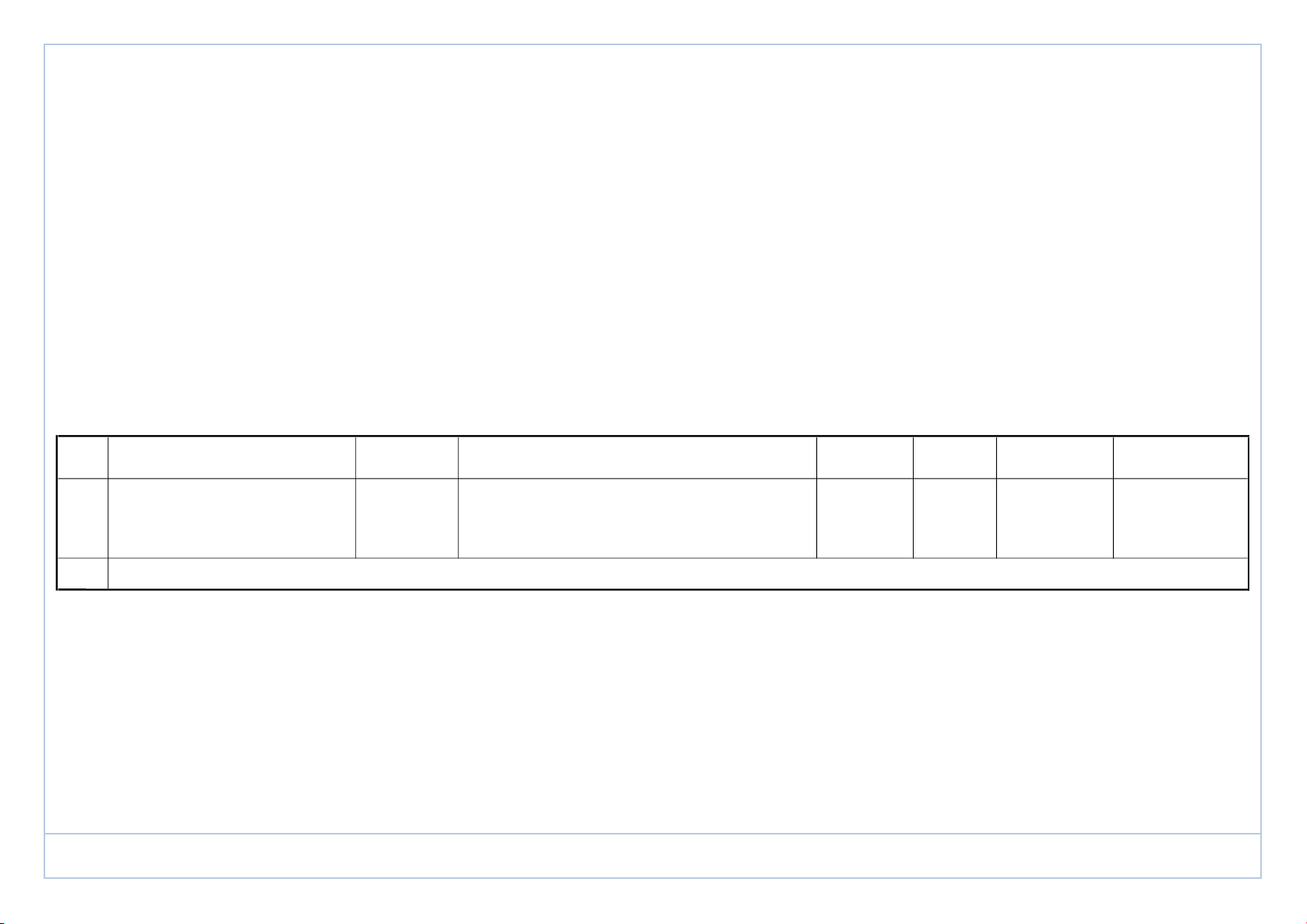
AM IF ALIGNMENT
STEP
SIGNAL SOURCE (AM RF Gen.) CONNECT
TO
SET SIGNAL TO ALIGNMENT INDICATOR (Oscilloscope, VTVM) CONNECT TO
SET RADIO DIAL
TO
ADJUST ADJUST FOR REMARKS
TP 4 Volume control at
1 A standard radiation
460KHz
Detector output terminal Quiet Maximum min. position
loop and TP 2 ground Point T 2
2 Repeat step 1 for max. output
FM IF ALIGNMENT
This model requires no FM IF alignment as the IF is fixed by ceramic filter and discriminator CF 1 & CF 2. Please take note th
at correct type and same color dot of ceramic filter is used
in servicing, diff color dot of ceramic filter may cause worse IF 'S' curve characteristic and distortion.
Connect IF genescope output terminal to TP 3 & TP 2 (GND) in series with a 100 Pf capacitor, connect scope input terminal to T
P 4 & TP 2 (GND), then the IF characteristic curve can be
observed.
ǵ
Musik Boy 50L RP 5240 LW
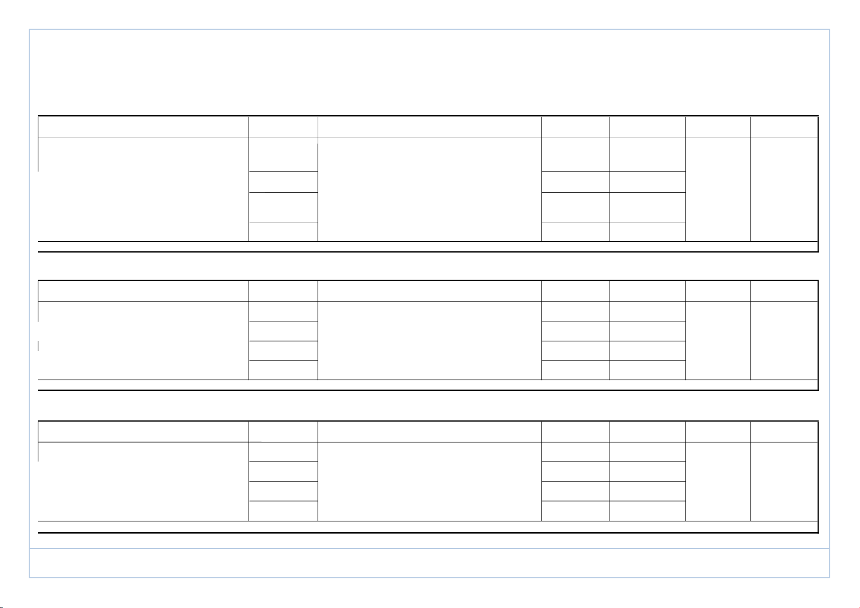
A L I G N M E N T P R O C E D U R E
MODEL NO.: GRUNDIG RP5240LW
SIGNAL SOURCE (FM Signal Gen.) CONNECT TO SET SIGNAL TO ALIGNMENT INDICATOR (Oscilloscope, VTVM) CONNECT TO
SET RADIO DIAL
TO
ADJUST ADJUST FOR REMARKS
L 4
87.35 MHz (Lowest end) stretch or
(modulated) squeeze
TP 1 108.25 MHz Terminals VC1 B Volume
through matching network (modulated) across speaker (Highest end) (Osc. trimmer) Maximum control at
if necessary voice coil L 3 (RF coil) max. position
88 MHz 88 MHz stretch or
(modulated) squeeze
106 MHz VC1 C
(modulated) 106 MHz (RF trimmer)
Repeat steps 3 and 4 as necessary to minimize tracking error and also steps 1 and 2 if necessary
SIGNAL SOURCE (AM Signal Gen.) CONNECT TO SET SIGNAL TO ALIGNMENT INDICATOR (Oscilloscope, VTVM) CONNECT TO
SET RADIO DIAL
TO
ADJUST ADJUST FOR REMARKS
515 KHz L 5
(modulated) (Lowest end) (Osc. coil)
1640 KHz VC1 A Volume
A standard radiation (modulated) Across speaker (Highest end) (Osc. trimmer) Maximum control at
loop ant. 558 KHz voice coil L 2 max. position
(modulated) 558 KHz (ant. coil)
1440 KHz VC1 D
(modulated) 1440 KHz (ant. trimmer)
Repeat steps 3 and 4 as necessary to minimize tracking error and also steps 1 and 2 if necessary
SIGNAL SOURCE (LW Signal Gen.) CONNECT TO SET SIGNAL TO ALIGNMENT INDICATOR (Oscilloscope, VTVM) CONNECT TO
SET RADIO DIAL
TO
ADJUST ADJUST FOR REMARKS
142 KHZ
(modulated) (Lowest end) NA
292 KHz Terminals TC 3 Volume
A standard radiation (modulated) across speaker (Highest end) (Osc. trimmer) Maximum control at
loop ant. 153 KHz voice coil L 6 max. position
(modulated) 153 KHz (ant. coil)
261 KHz TC 4
(modulated) 261 KHz (ant. trimmer)
Repeat steps 3 and 4 as necessary to minimize tracking error and also steps 1 and 2 if necessary
ǵ
Musik Boy 50L RP 5240 LW
 Loading...