

Page 1
COLOR TELEVISION
VISION+26
LXW 68-9740 Dolby
VISION+32
LXW 82-9740 Dolby
Page 2

2
CONTENTS____________________________________________
3-4 Set-up and safety
5-6 Connection and preparation
5 Connecting the antenna and power cord
6 Putting batteries in the remote control
7-10 Overview
7 Connections on the television set
8-9 The remote control (TV mode)
9 Operating controls on the television
10 The remote control (teletext mode)
11 Settings
11 Tuning television channels
11 Picture and sound settings
12 Easy Dialog system
12 »Easy Dialog System« – the interactive operating manual
13-14 TV mode
13 Basic functions
14 Zapping function
15-17 The Grundig TV Guide
15 The electronic television programme guide
16 Setting up the TV Guide
16 Sorting TV programmes
17 TV Guide settings
18-19 Teletext mode
18 TOP text or FLOF text mode
18 Normal text mode
18-19 Additional functions
20-25 Using external devices
20-22 Connecting external devices
22 Changing the AV settings
23 Video recorder, DVD player or set-top box
23 Headphones
24 Decoder or satellite receiver
24 Digital multi-channel amplifier/AV receiver
25 Camcorders
26 Operation as a PC monitor
26 Connecting a PC
27-30 Retrofitting a digital receiver
27 Connecting a micro digital receiver to a television set
28 Installing on the television set
29-30 Operating the receiver with the television remote control
31-33 Information
31 Technical data, Service information for dealers, Environmental note
29 Troubleshooting
30 Additional Information for units sold in the UK.
Page 3
ENGLISH
3
SET-UP AND SAFETY___________________________
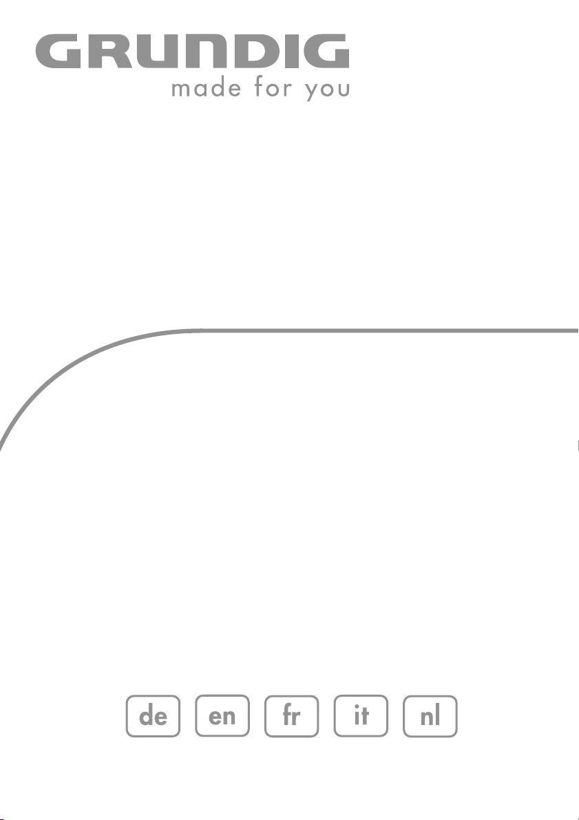
Please note the following instructions when setting up the television set:
This television is designed to receive and display video and audio signals.
Any other use is expressly prohibited.
The ideal viewing distance is five times the diagonal screen size.
Light falling on the screen impairs picture quality.
To assure sufficient ventilation make sure there is enough space
around it in the wall unit.
The television is designed for use in dry rooms. If you do use it outdoors,
make sure it is protected from moisture such as rain or splashing water.
Never expose the television set to moisture.
Do not place any vessels such as vases on the television, as they may
spill liquid, thus presenting a safety risk.
Place the television on a hard, level surface. Do not place any objects
such as newspapers on the television or put cloth or similar items
under it.
Do not place the television close to heating units or in direct sunlight, as
this will impair cooling.
Heat build-up can be dangerous and shortens the service life of the television. For reasons of safety, have a repairman remove any dirt in the
set from time to time.
Never open the television under any circumstances. No warranty claims
are accepted for damage caused by incorrect handling.
Make sure the power cord or the power supply unit (if provided) are not
damaged.
The television set may only be operated with the mains cable/adapter
supplied.
Thunderstorms are a danger to all electrical devices. Even when the television is switched off, it can be damaged by a lightning strike to the
mains or the antenna. Always disconnect the mains and antenna plugs
during a storm.
Use a damp, soft cloth to clean the screen. Do not use water with soap
or detergent.
Note:
Do not connect any other equipment while the device is switched on.
Switch off the other equipment as well before connecting it.
Do not plug in the power cord of your device until you have connected
the external equipment and the antenna.
Make sure the power plug is freely accessible.
! SERVICE !! SERVICE !
10
cm
20
cm
! SERVICE !
TV R
20 cm
VIDEOLRAUDIO IN
DVI
SERVICE
AV2
SP-DIF
YPbPr
DVI-I HDMI
AUDIO IN
G-BUS
OPTICAL OUT
AV1
LINE OUT
COMPONENT INPUT
AC IN
VIDEOLRAUDIO IN
DVI
AV2
SP-DIF
YPbPr
DVI-I HDMI
AUDIO IN
OPTICAL OUT
AV1
LINE OUT
COMPONENT INPUT
rieg am
K
SERVICE
G-BUS
10
cm
olf
G
AC IN
Page 4

4
When deciding where to put the device, remember that furniture is often
coated with various types of varnish and plastic. Many of these contain
chemicals which can corrode the feet of the device, leaving marks on the
surface of the furniture which can be difficult or impossible to remove.
The screen of your LCD television meets the highest quality standards
and has been checked for pixel faults.
Despite the great care taken in manufacturing, it is technically impossible to guarantee that some pixels will not be defective.
Provided they are within the thresholds specified by the DIN norm, pixel
faults of this kind cannot be regarded as a defect as defined by the
warranty.
Caution:
If you want to use a wall bracket for your television, make sure you read
the assembly instructions for the wall bracket carefully or have your specialist dealer mount it for you.
When buying the wall bracket, make sure that all the fastening points
needed on the television are there on the wall bracket and that they are
all used when it is mounted.
SET-UP AND SAFETY___________________________
Page 5
ENGLISH
5
CONNECTION AND PREPARATION
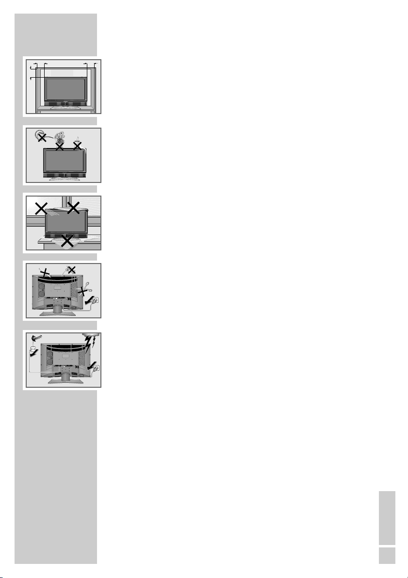
Connecting the antenna and power cord
1 Plug the roof antenna cable into the antenna socket »É« on the
television.
2 Plug the power cord supplied into the power socket on the tele-
vision.
3 Plug the power cord into a wall socket.
Notes:
Do not plug in the power cord of your device until you have
connected the external equipment and the antenna.
Only connect the television using the power cord supplied to a
suitable earthed safety socket.
Do not use an adapter plug or extension lead which does not
meet the applicable safety standards. Do not tamper with the
power cord.
1
2 3
U
Y
T
AC IN
TV R
AV 2
AV 1
SP-DIF
OPTICAL OUT
VIDEOLRAUDIO IN
AV2
AV1
LINE OUT
DVI
SP-DIF
YPbPr
DVI-I HDMI
AUDIO IN
OPTICAL OUT
COMPONENT INPUT
SERVICE
G-BUS
AC IN
Page 6

6
High definition – HD ready
Your television can playback high-definition television signals (HDTV).
You can connect the input sources (HDTV set-top box or High Definition
DVD player) to the »
HDMI
« or »
DVI-I
« socket (digital HDTV signal).
This ensures that you can view digital HDTV programmes, even if they
are copy-protected (HDCP High Bandwidth Digital Content Protection).
Putting batteries in the remote control
1 Open the battery compartment by taking off the lid.
2 Put in the batteries (AA, 2 x1,5 V).
Make sure the polarity is correct.
3 Close the battery compartment.
Note:
If the television no longer reacts properly to remote control commands, the batteries may be flat. Always remove used batteries. The manufacturer accepts no liability for damage caused
by leaking batteries.
Environmental note
Batteries, including those which contain no heavy metal, should
not be disposed of with household waste. Please dispose of
used batteries in an environmentally sound manner. Find out
about the legal regulations which apply in your area.
CONNECTION AND PREPARATION
Page 7
ENGLISH
7
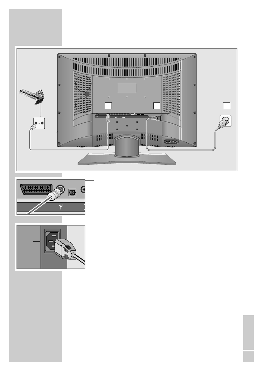
Connections on the television set
yy
LINE OUT Headphone socket/audio output.
AV 2 SCART socket
(FBAS-Signal, RGB-Signal, Y/C-Signal).
AV 1 SCART socket
(FBAS-Signal, RGB-Signal, Y/C-Signal).
É Antenna socket.
SP-DIF Audio output for PCM signals;
OPTICAL OUT for connecting a digital multi-channel audio/video
amplifier or AV receiver.
COMPONENT
INPUT
VIDEO Y Pb Pr Video input (YUV signal).
AUDIO IN L R Audio input (YUV signal, DVI signal).
DVI AUDIO IN Audio input (DVI signal).
DVI-I DVI-I socket, video input (DVI signal).
HDMI HDMI socket, audio/video input (HDMI).
SERVICE G-BUS Service socket for dealers.
Controlling external modules (DVB-T, DVB-S).
AC IN Power cord socket.
L AUDIO R Audio input for camcorder (red and white socket).
VIDEO Video input for camcorder (yellow socket).
S-VIDEO Video output for S-Video camcorder.
OVERVIEW____________________________________________
LINE OUT
VIDEOLRAUDIO IN
DVI
AV2
SP-DIF
YPbPr
OPTICAL OUT
AV1
LINE OUT
AV 2
AV 1
SP-DIF
OPTICAL OUT
COMPONENT INPUT
VIDEO
YPbPr
COMPONENT INPUT
LR
SERVICE
DVI-I HDMI
AUDIO IN
G-BUS
AC IN
AUDIO IN
DVI
AUDIO IN
DVI-I HDMI
SERVICE
G-BUS
Page 8
8
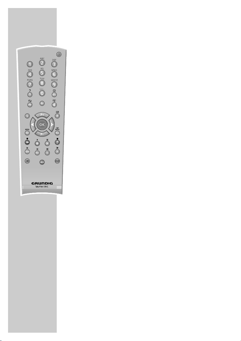
The remote control (TV mode)
Ǽ Switches the television off (standby).
1…0 Switches the television on from standby mode.
Selects channels directly.
? Calls up information on the selected function.
E
Opens the »Format« menu.
Then use P+ or P- to make the selection.
PIP Displays an inset picture.
Returns to normal picture.
AV Opens the pre-selection for AV channels.
Then selection with P+ or P-.
d Sound on/off (mute).
i Opens the »EASY DIALOG« menu.
Z Zapping function.
P+, P- Switch the television on from standby.
Select channels step by step.
Move the cursor in the menus up and down.
ǸǷ Adjust the volume.
Move the cursor left/right.
OK Opens the channel list.
Activates various functions.
TXT Switches between teletext and TV modes.
TV-G Opens the TV Guide (electronic programme guide.
(TV Guide providers are not available in all countries.)
z
Opens the »Picture« menu.
Ȅ Shows/hides the time and preset information.
ǷǷ
Freeze-frame.
F
Opens the »Sound« menu.
OVERVIEW____________________________________________
Page 9
ENGLISH
9
OVERVIEW____________________________________________
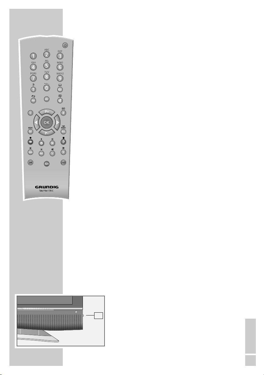
SCAN Functions in teletext mode.
PAT Selects the split screen function.
S Functions in teletext mode.
P Functions in teletext mode.
DR, DVD Switches to operation of a GRUNDIG digital receiver,
GRUNDIG digital receiver with hard disk (PDR),
GRUNDIG DVD players or GRUNDIG DVD
recorder.
Keep the appropriate button (»DR«, »DVD«) pressed
down. Then press the button.
Note:
The »DR« button has been programmed for operating
a GRUNDIG digital receiver (remote control level 1).
The »DVD« button has been programmed for operating a GRUNDIG DVD player.
You can change this programming, see »AUX«
button.
The functions available depend on the model of the
device you are using.
Just try it out.
AUX Programming the remote control for the operation of
external devices.
Press »AUX« and hold it down and press three
number buttons to enter the code:
»1«, »2«, »3« for a GRUNDIG DVD player.
»4«, »5«, »6« for a GRUNDIG DVD recorder.
»1«, »4«, »7« for a GRUNDIG digital receiver
(remote control level 1).
»2«, »5«, »8« for a GRUNDIG digital receiver
(remote control level 2).
»3«, »6«, »9« for a GRUNDIG digital receiver with a
hard disc (PDR).
Operating controls on the television
IO Power switch, switches the device on and off.
IO
Page 10
10
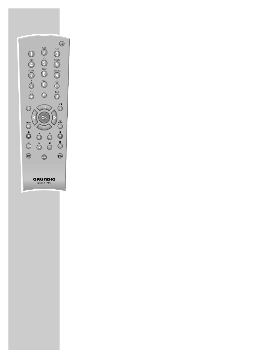
The remote control (teletext mode)
1 … 0 Enter teletext page numbers.
E
Switches to double character height.
i Opens page 100.
P+ Scrolls to the next page.
P- Scrolls back a page.
TXT Switches between teletext and TV modes.
zz
(red) Scrolls back a page.
ȄȄ
(green) Scrolls to the next page.
ǷǷ
(yellow) Selects the next chapter.
FF
(blue) Selects the next topic.
SCAN Overriding wait time.
S Calling up a sub-page directly.
P Page stop.
? Reveal answer.
OVERVIEW____________________________________________
Page 11
ENGLISH
11
Tuning television channels
The television is equipped with automatic tuning.
You start the search and can then sort the channels into your order
of preference.
There are 99 presets, to which you can assign channels from the
antenna or from the cable connection.
You can delete channels from the list which were found more than
once or which have poor reception.
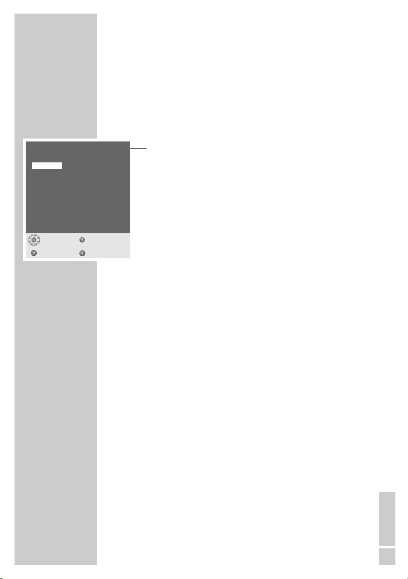
1 The first time you switch on the television, press »P+«, »P-« to
select the dialogue language and »OK« to confirm.
2 Select your location with »P+« or »P-« and press »OK« to
confirm.
– Automatic tuning begins.
– The process may take several minutes depending on the
number of channels received.
– After automatic tuning is completed, the television switches to
preset 1.
Note:
In the »Preset list« menu, you can sort channels as required.
You can also add channels which come on air subsequently.
You can find more detailed instructions in the » Easy Dialog
System« interactive operating manual.
The Easy Dialog System is described on page 12.
Picture and sound settings
1 Select the »Picture« menu by pressing »z« or the »Sound«
menu by pressing »F«.
2 Select the item with »P+« or »P-« and press »OK« to confirm.
3 Change the setting with »
Ǹ
«, »Ƿ«, »P+« or »P-«.
4 Exit the »Picture« menu or the »Sound« menu by pressing »
i«.
Note:
You can find detailed instructions on the settings in the » Easy
Dialog System « interactive operating manual.
The Easy Dialog System is described on page 12.
Virtual Dolby Surround: Under license from Dolby Laboratories
Licensing Corporation.
DOLBY and the Double-D symbol
ij are registered trademarks
of the Dolby Laboratories Licensing Corporation.
SETTINGS ______________________________________________
Menu language
Select
and confirm
Help
Deutsch
English
Français
Italiano
Nederlands
Español
Português
Dansk
Suomi
Norsk
Svenska
Română
âesky
Slovensky
Magyar
Polski
Slovensko
бгск
Hrvatski
Ελληνικά
Türkçe
усск
Back Exit
Page 12

12
»Easy Dialog System« – the interactive operating
manual
Your television features the »Easy Dialog System« – a kind of interactive operating manual.
This interactive operating manual has menus, a user guide and a
help function to show you how to operate the television and the
many numerous feature it offers.
The printed operating manual only shows you how to set up the
television and provides a general overview, and is therefore very
concise.
How the »Easy Dialog System« works
The main »Easy Dialog« menu is your television’s control centre.
This main menu is the contents page of the »Easy Dialog Systems«.
Press »i « to open it.
You can select each menu item directly by pressing »1…0 «.
Alternatively you can select by pressing »P+«, »P-« and then
»OK« to confirm.
The user guide at the bottom of the menus shows you what functions
each button performs.
If you want an explanation of a function, just press »
D
«.
What happens if you accidentally select the wrong menu item? No
problem – just press »
F
« to return to the previous menu.
Once you have made all your settings or have finished reading the
interactive operating manual, press »i « to return to TV mode.
Just try it out. You can’t go wrong.
EASY DIALOG SYSTEM_______________________
1 Settings
2 Preset list
3 Installation
4 Remote control
ǵ
ŃEASY DIALOG
Help
Exit
Select
and open
●
OK
Page 13

ENGLISH
13
TV MODE_______________________________________________
Basic functions
Switching on
1 Press »IO« on the television to switch it on.
Press »1…0« or »P+« or »P-« to switch on the device from
standby mode.
Note:
This television is equipped with a highly-sophisticated computer.
After switching on the television, it takes about 20 seconds until
the operating system is loaded and you will then see a
picture.
Switching to and from standby
1 Press »Ǽ« to switch the television to standby.
2 Press »IO« on the television set to switch it off completely.
– This saves electricity.
Selecting channels
1 Press »1…0« to select channels directly.
2 Press »P+« or »P-« to move up and down presets one at a
time.
3 Open the channel list by pressing »OK«, select the station with
»P+« or »P-« and press »OK« to confirm.
Selecting AV channels
1 To select AV channels, press »AV« to open the AV menu, press
»P+« or »P-« to select the AV preset and »OK« to confirm.
Adjusting the volume
1 Press »Ǹ« or »Ƿ« to change the volume.
Muting
1 Press »p« to mute the sound or switch it on again.
Showing and hiding programme information,
the date and time
1 Press »Ȅ« to show or hide the information.
Changing the picture format
The television automatically switches to the 16:9 format if this format is detected via the SCART socket.
1 To select the picture format, press »
E
« to open the »Picture
format« menu and press »P+« or »P-« to select the format.
Page 14

14
Freeze-frame
If you wish to view a particular scene for longer, you can “freeze”
the frame of the current programme.
1 Press »
ǷǷ
« (yellow).
2 Press »
ǷǷ
« (yellow) again to quit the function.
Split screen
This function shows the television channel on the right and the teletext page on the left.
1 Activate the spilt screen function by pressing »PAT«.
– The television channel and the teletext page appear next to
each other on the screen.
2 Deactivate the spilt screen function by pressing »PAT«.
Zapping function
This function remembers the channel you are currently watching
while you switch over to other channels (zapping).
1 Press »1…0« or »P+« »P-« to select the channel to be stored
in the zapping memory (e.g. Channel 7, PRO7) and press »Z«
to save it.
– The channel name appears on the screen, e.g. »Z 7 PRO7«.
2 Press »1…0« or »P+« »P-« to switch over to another channel.
3 Each time you press »Z« the television switches between the
channel in the memory (in this case PRO7) and the last one you
were watching. This action is called zapping.
4 Press »
i« to quit the zapping function.
– The display disappears.
TV MODE_______________________________________________
›
Z 7 PRO7
Page 15

ENGLISH
15
The electronic television programme guide
The TV Guide is an electronic programme guide which provides a
fast and up-to-date overview of all the pre-programmed television
programmes.
Options
Programme information is provided in a database which allows you
to sort information in various ways, according to the following:
– Programmes from all the broadcasting stations
– Programmes from one broadcasting station
– Programmes which are currently being broadcast from all stations
– Programmes which are currently being broadcast from one station
– You can select programmes according to topics, such as feature
films, sports broadcasts, from all stations or only one.
– Programmes sorted according to the time. For example, the
current programme (NOW), the programme on next (NEXT) or
programmes on after a specific time.
Who provides TV Guide?
Certain stations provide a TV Guide for almost all programmes.
The programme information is available for several days.
How TV Guide works
First you need to find a TV Guide provider and then activate the TV
Guide.
Select a preset for the TV Guide provider and the information is
imported. This information is stored even if you switch off and then
on again.
It takes between 20 and 30 minutes to load all the information to
the television but you can view the information that is closer to the
current time after a few minutes.
The TV Guide is updated automatically as long as you have selected
the preset for the TV Guide provider.
Notes:
TV Guide is not available when operating via an external
receiver (analogue satellite receiver, DVB-S, DVB-T).
If you change the preset while the device is transferring the
data, it is possible that not all information will be loaded.
Note the explanations to the individual functions, which you
can always view with »
D
«.
THE GRUNDIG TV GUIDE __________
Page 16

16
Setting up the TV Guide
1 Switch on the TV Guide with »TV-G«.
– The TV Guide appears on the television screen.
2 Select the television programme (TV Guide broadcaster) with
»P+«, »P-«, »
Ǹ
« or »Ƿ« and confirm with »OK«.
– Select a preset for the TV Guide provider and the information
will be imported.
Note:
If you are not sure which TV Guide data is being transferred,
you can start a search with »
Ȅ«.
Sorting TV programmes
You can sort TV programmes according to time, topic and station.
1 Switch on the TV Guide with »TV-G«.
– The TV Guide appears on the television screen with the topic
menu.
All programmes
Feature films
Sport
TV series
Children’s programmes
Shows and entertainment
News
2 To sort programmes according to the station, press »
F
« (blue)
or
to sort programmes according to time and day, press »Ȅ«
(green)
– In the overview menu you can see the day, NOW for current
programmes, NEXT for the next programmes and the times
for other programmes
or
to sort programmes according to topic, press »Ƿ« (yellow).
3 Select the station provider, time or the topic with »P+«or»P-«.
4 Select the programme with »
Ƿ
« and »P+«or»P-« and press
»OK« to switch to it.
5 Exit the TV Guide with »
i«.
all
THE GRUNDIG TV GUIDE __________
Page 17

ENGLISH
17
TV Guide settings
1 Open the »EASY DIALOG« menu by pressing »i«.
2 Select »Installation« with »P+« or »P-« and press »OK« to
confirm.
3 Select »TV Guide« with »P+« or »P-« and press »OK« to
confirm.
4 Press »P+« or »P-« to select the setting and press »OK« to
confirm.
5 Press »P+« or »P-« to change the setting and press »OK« to
confirm.
Note:
If you want an explanation of the setting, just press »
D
«.
6 Press »
i« to conclude the setting.
THE GRUNDIG TV GUIDE __________
Installation
TV Guide
1 TV Guide
2 Update in standby mode
3 Automatic restriction
4 Show station name
5 TV Guide Provider List
Help
Select
and open
●
OK
Back Exit
Yes
Yes
Off
Medium
Page 18

18
TOP text or FLOF text mode
1 Press »TXT« to switch on teletext.
2 You can select teletext pages directly by pressing »1…0«.
Press »
i« to return to page 100.
Note:
At the bottom of the screen there is an info bar with red, green
and – depending on the channel – yellow and blue panels. Your
remote control has buttons with the corresponding colours.
3 Press »
z
« (red) to go back a page.
4 Press »
Ȅ« (green) to go forward a page.
5 Press »
ǷǷ
« (yellow) to select a chapter.
6 Press »
F
« (blue) to select a topic.
7 Press »TXT« to switch off teletext.
Normal text mode
1 Press »TXT« to switch on teletext.
2 You can select teletext pages directly by pressing »1…0«.
3 Scroll back a page with »P-«.
4 Press »P+« to scroll to the next page.
5 Press »TXT« to switch off teletext.
Additional functions
Overriding wait time
1 Press »SCAN«.
– The television returns to television mode, the teletext page
numbers are displayed in the upper left corner of the screen.
2 Enter the teletext page number with »1...0«.
– The page number appears in red, when the page is found it
changes to green.
3 Switch to the teletext page by pressing »SCAN«.
TELETEXT MODE___________________________________
Page 19

ENGLISH
19
Increasing the character height
If you have difficulty reading the text on the screen, you can double
the character height.
1 To enlarge the character height of a teletext page, keep press-
ing »
E
«.
Page stop
A multiple page may contain several sub-pages, which are automatically scrolled by the transmitting station.
1 Stop the sub-pages with »P«.
2 Press »P« to quit the function.
Calling up a sub-page directly
If the selected teletext page contains further pages, the number
of the current sub-page as well as the total number of pages is
displayed.
1 Call up the sub-pages with »S«.
2 Select the sub-pages with »
z
« (red) or »Ȅ« (green).
3 End this sub-page function with »S«.
Reveal answer
Certain teletext pages contain hidden answers or information. These
can be viewed.
1 Display information with »?«.
2 Press »?« to conceal the information.
TELETEXT MODE___________________________________
Page 20

20
Operation with external devices
Note:
Which television socket(s) you connect your external devices to
depends on the sockets the external device is equipped with
and the signals which are available.
Remember that with many external devices, the resolution of the
video signal must be adjusted to the input sockets of the television (see the operating manual of the external device). You can
find out which values you need to set by referring to the guidelines in the section about connection options.
Note:
Do not connect any other equipment while the device is
switched on. Switch off the other devices as well before connecting them. Only plug the device into the mains socket after
you have connected the external devices.
High definition – HD ready
Your television can playback high-definition television signals (HDTV).
You can connect the input sources (HDTV set-top box or High Definition
DVD player) to the »
HDMI
« or »
DVI-I
« socket (digital HDTV signal).
This ensures that you can view digital HDTV programmes, even if they
are copy-protected (HDCP High Bandwidth Digital Content Protection).
Connecting external devices
... With a digital audio/video signal
Video signal: digital video; resolution: standard 480p, 576p; HDTV
720p, 1080i, 1080p.
Audio signal: digital audio (stereo, multi-channel compression,
uncompressed).
Preset »HDMI«.
1 Connect the »HDMI« socket on the television and the corre-
sponding HDMI socket on the external device using a standard
HDMI cable (digital video and audio signal).
USING EXTERNAL DEVICES_______________
A
DVI
UDIO IN
DVI-I HDMI
SERVICE
G-BUS
Page 21

ENGLISH
21
... With a digital audio/video signal
Video signal: digital video; resolution: standard 480p, 576p; HDTV
720p, 1080i, 1080p.
Audio signal: stereo, analogue.
Preset »DVI Digital«.
1 Connect the »DVI-I« socket on the television and the corre-
sponding DVI socket on the external device using a standard
DVI cable (digital video and audio signal).
2 Connect the »DVI AUDIO IN« (3.5 mm jack) or »AUDIO IN
L R« socket on the television and the corresponding sockets on
the external device using an RCA cable (audio signal).
Note:
In the »Devices« menu you may have to select the DVI audio
signal (see “Changing the AV settings” on page 22).
You can also connect a device with an HDMI socket to the DVI
socket. An adapter cable is supplied with the device.
... With an analogue video signal (progressive)
Video signal: YUV; resolution: standard 480p, 576p; HDTV 720p,
1080i.
Audio signal: stereo, analogue.
Preset »YPbPr«.
1 Connect the »COMPONENT INPUT VIDEO Y Pb Pr«
sockets on the television to the corresponding sockets of the
external device with RCA cables (video signal).
2 Connect the »COMPONENT INPUT AUDIO IN L R« sock-
ets on the television to the corresponding sockets of the external
device with RCA cables (audio signal).
... Using the SCART socket
Video signal: FBAS, Y/C, RGB.
Audio signal: stereo, analogue.
Preset »AV1« or »AV2«.
1 Connect the »AV 1« or »AV 2« socket on the television and
the corresponding socket on the external device using a SCART
cable (video and audio signal).
USING EXTERNAL DEVICES_______________
H
AUDIO IN
A
P
C
Pr LR
PONENT INPUT
bPrEOLR
OMPONENT INPUT
AUDIO IN
SP-DIF
OPTICAL OUT
AUDIO IN
DVI
DVI-I
DVI
AUDIO IN
VIDEO
YPbPr
COMPONENT INPUT
DVI-I
AUDIO IN
LR
LINE OUT
AV 2
AV 1
S
OPTI
Page 22

22
... With S-Video signal
Video signal: Y/C.
Audio signal: stereo, analogue.
Preset »C-AV«.
1 Connect the S-VIideo (S-VHS) socket on the television and the
corresponding socket on the external device using an S-Video
cable (video signal).
2 Connect the red and white (L AUDIO R) sockets on the television
to the corresponding sockets of the external device with RCA
cables (audio signal).
... With an analogue TV signal
Video signal: FBAS.
Audio signal: stereo, analogue.
Preset »C-AV«.
1 Connect the yellow (VIDEO) socket on the television to the cor-
responding socket of the external device with an RCA cable
(video signal).
2 Connect the red and white (L AUDIO R) sockets on the television
to the corresponding sockets of the external device with RCA
cables (audio signal).
Changing the AV settings
In the »Device connections« menu you can adjust the AV sockets to
the signals from the devices connected to them.
1 Open the »EASY DIALOG« menu by pressing »
i«.
– The »EASY DIALOG« menu appears.
2 Select »Installation« with »P+« or »P-« and press »OK« to
confirm.
– The »Installation« menu appears.
3 Select »Devices« with »P+« or »P-« and press »OK« to con-
firm.
– The »Devices« menu appears.
4 Select the AV socket with »P+« or »P-« and press »OK« to
confirm.
– The menu for the selected AV socket appears.
5 Select the line using »P+« or »P-« and press »OK« to confirm.
6 Make the setting with »P+« or »P-« and press »OK« to con-
firm.
Note:
If you want an explanation of the setting, just press »
D
«.
7 Press »
i« to conclude the setting.
USING EXTERNAL DEVICES_______________
Installation
1 Menu language
2 Country
3 Station search
4 Devices
5 Time and date
6 Special functions
7 Dealer service menu
Help
Select
and open
●
OK
Back Exit
Devices
AV1
1 Signal type
2 Switch voltage evaluation
3 RGB
4 RGB-level
5 Time constant
Help
Exit
Select
and open
●
OK
Back Show connectors
FBAS
Yes
Yes
Normal
TV
Page 23

ENGLISH
23
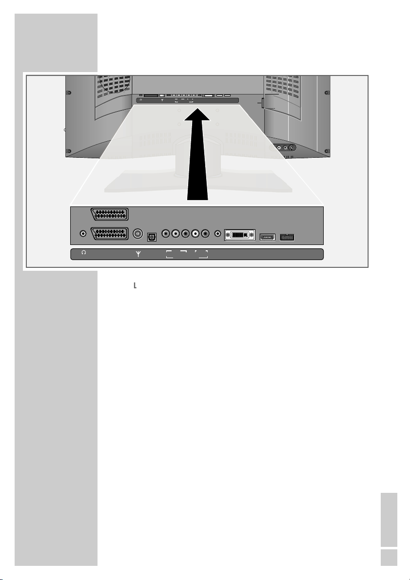
Video recorder, DVD player or set-top box
Connecting a video recorder, DVD player or
set-top box
1 Connect the socket of the television and the corresponding sock-
et of the video recorder, DVD player or set-top box with a
SCART cable.
Using a DVD player, DVD recorder, video
recorder or set-top box
1 Switch on the external device and select the function you want
to use.
2 Press »AV«, then use »P+« or »P-« to select the preset for the
input signal (»AV1«, »AV2«, »YPbPr«, »DVI Digital« or
»HDMI«) and press »OK« to confirm.
Headphones
Connecting the headphones
1 Plug the headphones (3.5 mm jack plug) into the headphone
socket on the back of the device.
Selecting audio settings for the headphones
1 Open the »Sound« menu by pressing »F«.
2 Select »Headphone sound settings« or »Headphone volume«
with »P+« or »P-« and press »
Ǹ
« or »Ƿ« to make the setting.
3 Press »
i« to conclude the setting.
USING EXTERNAL DEVICES_______________
VIDEOLRAUDIO IN
AV2
AV1
AUDIO OUT
DIGITAL AUDIO OUT
VIDEO OUT
L
EURO AV TV
S VIDEO OUT
R
110-240 V
~ 50/60Hz 20 W
LINE OUT
DVI
SP-DIF
YPbPr
DVI-I
AUDIO IN
OPTICAL OUT
COMPONENT INPUT
VIDEOLRAUDIO IN
DVI
AV2
AV1
LINE OUT
SERVICE
SP-DIF
YPbPr
DVI-I HDMI
AUDIO IN
G-BUS
OPTICAL OUT
COMPONENT INPUT
Page 24

24
Decoder or satellite receiver
A decoder is needed if the television receives encoded programmes
from a privately operated station.
Connecting a decoder or satellite receiver
1 Connect the »AV 1« socket on the television and the corre-
sponding socket on the decoder using a SCART cable.
Using a decoder or satellite receiver
1 Switch on the television and the decoder or satellite receiver.
2 Press »AV«, press »P+« or »P-« to select the »AV1« preset and
press »OK« to confirm.
Digital multi-channel amplifier/AV receiver
1 Plug a standard optical digital cable into the »SP-DIF OPTI-
CAL OUT« socket on the digital receiver and the correspond-
ing input socket on the digital multi-channel amplifier/
AV receiver.
USING EXTERNAL DEVICES_______________
Decoder
LINE OUT
S
T
N
r
VIDEOLRAUDIO IN
DVI
AV2
SP-DIF
YPbPr
OPTICAL OUT
AV1
LINE OUT
COMPONENT INPUT
PAY-TV
AV 2
AV 1
OP
SERVICE
DVI-I HDMI
AUDIO IN
G-BUS
AC IN
VIDEOLRAUDIO IN
DVI
AV2
AV1
LINE OUT
WT–A
AV 2
AV 1
SP-DIF
OPTICAL OUT
VIDEO
YPbP
COMPONE
SERVICE
SP-DIF
YPbPr
DVI-I HDMI
AUDIO IN
G-BUS
OPTICAL OUT
COMPONENT INPUT
AC IN
Page 25

ENGLISH
25
Camcorders
Connecting a camcorder
1 Connect the yellow »VIDEO« socket of the television and the
video output socket of the camcorder (VHS, Video 8) using an
RCA cable (video signal),
or
connect the »S-VHS« socket (video signal) of the television and
the S-Video output socket of the camcorder (VHS, Hi 8) using
an S-Video cable.
2 Connect the red and white »L AUDIO R« sockets on the televi-
sion to the audio output sockets of the camcorder using RCA
cables (audio signal).
Note:
In the »Devices« menu you may have to select the video signal
(see “Changing the AV settings” on page 22).
There must not be video signals at »VIDEO« and
»S-VHS« sockets at the same time. This could lead to picture
disturbances.
Operation with a camera recorder
1 Press »AV«, press »P+« or »P-« to select the »C-AV« preset and
press »OK« to confirm.
2 Switch on the camcorder, put in a cassette and start playback.
USING EXTERNAL DEVICES_______________
VIDEOLRAUDIO IN
DVI
AV2
SP-DIF
YPbPr
OPTICAL OUT
AV1
LINE OUT
COMPONENT INPUT
SERVICE
DVI-I HDMI
AUDIO IN
G-BUS
AC IN
Page 26

26
Connecting a PC
1 Connect the »DVI-I« socket on the television to the correspond-
ing socket on the PC using a DVI cable (digital video signal) or
a DVI – VGA cable (analogue video signal).
2 Connect the »DVI AUDIO IN« or »AUDIO IN L R« socket
on the television to the corresponding socket on the PC using a
suitable cable (audio signal).
Note:
Adjust your PC to the monitor (for example, picture resolution
1024 x 768, picture frequency 60 Hz).
In the »Devices« menu you may have to select the DVI audio
signal (see “Changing the AV settings” on page 22).
Selecting the preset for the PC
1 Press »AV«, then use »P+« or »P-« to select the »DVI Analog«
preset (analogue video signal) or »DVI Digital« (digital video
signal) and press »OK« to confirm.
OPERATION AS A PC MONITOR______
AUDIO IN
Pr
LR
AUDIO IN
AUDIO IN
AUDIO IN
PONENT INPUT
bPrEOLR
MPONENT INPUT
VIDEOLRAUDIO IN
DVI
AV2
SP-DIF
YPbPr
OPTICAL OUT
AV1
LINE OUT
DVI
DVI-I
DVI
DVI-I
SERVICE
DVI-I HDMI
AUDIO IN
G-BUS
COMPONENT INPUT
AC IN
Page 27

ENGLISH
27
Connecting a micro digital receiver
to a television set
You can retrofit your television with a micro digital receiver. Your
dealer can recommend an appropriate receiver for you.
The user guide for the receiver can be integrated into the television
user guide by following a brief installation procedure. After
installing, the receiver can be controlled with the television remote
control. The remote control, the infra-red mouse and the power supply for the receiver will then no longer be needed.
Connecting the communication line to the receiver
1 Plug the communication line into the »IR remote« and
»12 VDC« sockets.
Note:
The communication line is supplied with the television.
Connecting the communication line to the
television set
1 Plug the communication line into the »SERVICE G-BUS«
socket on the television.
Note:
The remote control, the infra-red mouse and the power supply
for the receiver will then no longer be needed.
RETROFITTING A DIGITAL RECEIVER
12 VDC, 18 W max.
AV2
AV1
SERVICE
AC IN
G-BUS
PIP
z
TV-G
TXT
Radio
TV
A/B
MHP
d
DR
DVD
TV
Tele Pilot 766 S
DVI-I HDMI
SERVICE
G-BUS
Page 28

28
Installing on the television set
1 Switch on the television.
2 Open the »EASY DIALOG« menu by pressing »
i«.
3 Select »Installation« with »P+« or »P-« and press »OK« to
confirm.
4 Select »Devices« with »P+« or »P-« and press »OK« to con-
firm.
5 Select »G-Bus« with »P+« or »P-« and press »OK«
to confirm.
6 Select »Picture signal on plug« with »P+« or »P-« and press
»OK« to confirm.
7 Select the Euro AV socket with »P+« or »P-« and press »OK«
to confirm.
8 Select »Install external module« with »P+« or »P-« and start
the installation with »OK«.
Note:
When the installation has been successfully completed, the
»First Time Installation« page appears.
You can find further settings in the digital receiver user guide.
RETROFITTING A DIGITAL RECEIVER
1 Settings
2 Rreset list
3 Installation
4 Remote control
ǵ
ŃEASY DIALOG
Help
Exit
Select
and open
●
OK
Devices
G-Bus
2 Install external module
1 Picture signal on plug
Help
Select
and open
●
OK
Back Exit
AV1
Page 29

ENGLISH
29
RETROFITTING A DIGITAL RECEIVER
Operating the receiver with the television remote
control
Note:
The receiver must be connected and installed to the G bus on the
television set via the communication line.
Ǽ Switches the television off (standby).
1…0 Switches the television on from standby mode.
Selects channels directly.
? Displays information on the selected function.
You receive the station information of the digital
receiver after changing station or by looking in the
electronic TV guide.
E
Opens the »Format« menu.
Then use P+ or P- to make the selection.
PIP Displays an inset picture.
Returns to normal picture.
AV Opens the pre-selection for AV channels.
Then select with P+ or P-.
d Sound on/off (mute).
i Opens the television »EASY DIALOG« menu
(main menu).
You can find the main menu of the digital receiver in
the »EASY DIALOG« menu.
Z Switches back one menu level in the receiver.
P+, P- Switch the television on from standby;
Select stations step by step;
Move the cursor in the menus up and down.
ǸǷ Adjust the volume;
Move the cursor left/right.
OK Opens the station or favourites list on the receiver;
activates various functions.
TXT Switches between teletext mode and TV mode on the
television (only the television teletext can be used).
TV-G Opens and closes the electronic TV guide on the
receiver.
Page 30

30
z
Opens the »Picture« menu of the television.
Ȅ Shows/hides the time and station information.
ǷǷ
Freeze-frame.
F
Opens the »Sound« menu of the television.
SCAN Switches to TV mode.
PAT Selects the split screen function.
S Switches to radio mode.
P Switches between the last two selected stations;
Switches from the station list to the favourites.
DR, DVD Switches to operation of a GRUNDIG digital receiver,
GRUNDIG digital receiver with hard disc (PDR),
GRUNDIG DVD players or GRUNDIG DVD
recorder.
Keep the appropriate button (»DR«, »DVD«) pressed
down. Then press the appropriate button.
Note:
The »DR« button has been programmed for operating
a GRUNDIG digital receiver (remote control level 1).
The »DVD« button has been programmed for operating a GRUNDIG DVD player.
You can change this programming, see the »AUX«
button.
The functions available depend on the model of the
device you are using.
Just try it out.
AUX Programmes the remote control for the operation of
external devices.
Press »AUX« and hold it down and then simultaneously press three number buttons to enter the code:
»1«, »2«, »3« for a GRUNDIG DVD player.
»4«, »5«, »6« for a GRUNDIG DVD recorder.
»1«, »4«, »7« for a GRUNDIG digital receiver
(remote control level 1).
»2«, »5«, »8« for a GRUNDIG digital receiver
(remote control level 2).
»3«, »6«, »9« for a GRUNDIG digital receiver with a
hard disc (PDR).
RETROFITTING A DIGITAL RECEIVER
Page 31

ENGLISH
31
Technical data
Mains voltage: 230 V, 50/60 Hz,
(power supply control range 190 to 264 V)
Power consumption: 107 W during operation (Vision+ 26)
145 W during operation (Vision+ 32)
approx. 2 W in standby mode
Audio output stage: Front 2 x 10 W music power
(2 x 6 W sine wave)
Subwoofer 18 W music power
(10 W sine wave)
Reception ranges: C01 … C99, special channels S01 … S41
Preset channels: 99 and 7 AV
Screen size: 66 cm / 26” (Vision+ 26)
81 cm / 32” (Vision+ 32)
Max. resolution: WXGA 1366 x 768
Weight (WEEE): 18.81 kg (Vision+ 26)
25.31 kg (Vision+ 32)
Service information for dealers
The product complies with the following EU directives:
73/23/EEC directive on electrical equipment for use within certain
voltage limits. 89/336/EEC, 2006/95/EG directive on electromagnetic compatibility.
The device complies with the following standards: EN 60065,
EN 55013, EN 55020.
Environmental note
This product has been made from high-quality parts and materials
which can be re-used and recycled.
Therefore, do not throw the product away with normal household
waste at the end of its life. Take it to a collection point for recycling
electrical and electronic devices. This is indicated by this symbol on
the product, in the operating manual and on the packaging.
Please find out about collection points operated by your local
authority.
Help protect the environment by recycling used products.
INFORMATION_____________________________________
Modifications and errors reserved.
Page 32

32
Problem
Screen lit (snow or blue),
but no picture
Poor contrast
No colour
Sound unclear
Ghosting, reflection
Picture but no sound
Teletext impaired or absent
Remote control does not
work
Parental control warning
appears when switched on
You cannot understand the
menu language
No picture/sound on AV
preset (SCART socket)
INFORMATION_____________________________________
Possible cause
Antenna cable
Picture settings shifted
Problem at station
Colour intensity too low
TV standard setting (if
setting option is available)
Problem at station
Sound setting
Channel setting
Antenna
Volume turned down or
speaker switched off
Audio control via RCA
audio sockets activated (if
this option is available)
Problem at station
Television station has no
teletext or antenna system
Station signal too weak
(picture interference)
No optical connection
Remote control batteries
Operating mode undefined
Parental control has been
activated
Wrong menu language set
The SCART cable is not connected correctly
Remedy
Antenna cable connected?
Check antenna?
Adjust the brightness, contrast or colour setting
Test with a different channel
Turn up the colour
Select the correct colour
standard
Test with a different channel
Correct the sound setting
Automatic or manual tun-
ing/fine tuning
Have antenna cable or sys-
tem checked
Turn up or switch on the vol-
ume
Select sound output via
loudspeaker
Test with a different channel
Test with a different channel,
fine tuning may eliminate
ghosting or reflections
Check antenna
Point remote control at television
Check the batteries, change if
necessary.
Ensure correct
polarity
Switch off the television with
the power button for 2 minutes
Enter secret number or
number combination
7038580.
Select the »Language« menu
with »i«, »3«, »OK« and
set the correct language
Plug in the cable properly
Troubleshooting
If the remedies given below do not work, please consult an authorised GRUNDIG dealer. Please bear in mind that malfunctions can
also be caused by external devices such as video recorders or satellite receivers.
NOTE:
This is a Class A product. During operation the device can cause radio interference. In
this case the user may have to remedy this. Please contact your specialist dealer.
Page 33

ENGLISH
33
Additional Information for units sold in the UK.
Units sold in the UK are suitable for operation from a 240V ac, 50Hz mains
supply.
The range of multi-system receivers is built to work in most European countries. However, the mains plug and socket system for the UK differs from
many European countries.
This appliance has been supplied with a fitted, non-removable, approved
converter plug for use in the UK. This converter plug is fitted with a 5A rated
fuse.
In case this appliance is supplied with a moulded 2-pin Euro plug only,
which is unsuitable for UK operation, this must be cut off and immediately
disposed of. An approved 13A, 3-pin UK plug should then be fitted by a
qualified electrician.
Note:
The severed Euro plug must be destroyed to avoid a possible shock
hazard should it be inserted into a socket elsewhere.
If a non-rewireable 3-pin plug or a rewireable 13A (BS1363) 3-pin plug is
used, it must be fitted with a 5A ASTA or BSI approved BS1362 fuse. If any
other type of plug is used it must be protected by a 5A fuse either in the
plug, or at the distribution board. If this type of plug becomes defective,
ensure that the fuse is removed before disposal, to eliminate potential shock
hazard.
If it is necessary to change the fuse in the non-rewireable plug, the correct
type and rating (5A ASTA or BSI approved BS1362) must be used and the
fuse cover must be refitted. If the fuse cover is lost or damaged, the lead and
plug must not be used until a replacement is obtained. Replacement fuse
covers should be obtained from your dealer.
Important:
The wires in the mains lead are colour coded in accordance with the following code:
BLUE – NEUTRAL
BROWN – LIVE
As the colours of the wires in the mains lead of your appliance may not correspond with the coloured marking identifying terminals in your plug, proceed as follows:
Connect the BLUE coloured wire to plug terminal marked with the letter “N”
or coloured black.
Connect the BROWN coloured wire to the plug terminal marked with the letter “L” or coloured red.
In no circumstance must any of the wires be connected to the terminal marked with the letter “E”, earth symbol “
z”, coloured green, or green & yel-
low.
INFORMATION_____________________________________
Page 34

Grundig Multimedia B.V.
Atrium, Strawinskylaan 3105 • NL-1077 ZX Amsterdam • http://www.grundig.com
07/24
 Loading...