

Grundig GV 3205 VPS, GV 3243 HiFi, GV 3242 NIC-2, GV 6263 HiFi, SE 1400 SV Service Manual [en, de]
...Page 1
Video Service Manual
2. Ergänzung / Supplement 2
VIVANCE
GV 3200 VPS GMJ3700
GV 3205 VPS GMJ4200
GV 3242 NIC/1 GMJ4600
GV 3242 NIC/2 GMJ4700, GMJ5900
GV 3243 HiFi GMJ4400, GMJ4500
GV 3245 HiFi GMJ5400
GV 3247 HiFi GMJ5700
XERIA
GV 5253 HiFi GMJ6000
GV 6262 NIC GMJ5300
GV 6263 HiFi GMJ5100, GMJ5200
GV 6265 HiFi GMJ5500
VIDEO IN L AUDIO IN R
Zusätzlich erforderliche Unterlagen für den Komplettservice
Additionally required Service Documents for the Complete Service
Service
Manual
Sicherheit
Safety
Materialnr./Part No.
720108000000
Palermo
P
SE 1400 SV GMJ4100
Sevilla
SE 1405 HiFi/NIC GMJ4900
Grundig Service
Hotline Deutschland…
Technik:
TV
TV
SAT
VCR/LiveCam
HiFi/Audio
Car Audio
Telekommunikation
Planatron
Ersatzteil-Verkauf: Mo.-Fr. 8.00-19.00 Uhr
Kundendienst/Werkstätten:
gebührenpflichtig
(8.00-22.00 Uhr)
…Mo.-Fr. 8.00-18.00 Uhr
0180/52318-41
0180/52318-49
0180/52318-48
0180/52318-42
0180/52318-43
0180/52318-44
0180/52318-45
Fax:
Telefon: 0180/52318-40
Telefon:
Fax:
0180/52318-51
0180/52318-99
0180/52318-50Fax:
Mo.-Fr. 8.00-18.00 Uhr
0180/52318-52
0180/52318-46
Materialnummer/Part Number 720105411000
Änderungen vorbehalten/Subject to alteration • Printed in Germany WÜ
H-S 41 0802 • 8002/8012, 8003/8013
http://www.grundig.com
Page 2

Allgemeiner Teil / General Section GV 32…, GV 52…, GV 62…
Es gelten die Vorschriften und Sicherheitshinweise
gemäß dem Service Manual "Sicherheit", Materialnummer 720108000000, sowie zusätzlich die eventuell abweichenden, landesspezifischen Vorschriften!
D
Inhaltsverzeichnis
Seite
Allgemeiner Teil ................................. 1-3…1-19
Geräteübersicht ........................................................................... 1-3
Messgeräte / Messmittel .............................................................. 1-4
Technische Daten ........................................................................ 1-4
Servicehinweise ........................................................................... 1-5
Bedienhinweise ............................................................................ 1-7
Abgleichvorschriften .................................... 2-1
Platinenabbildungen
und Schaltpläne ................................. 3-1…3-28
Verdrahtungsplan ......................................................................... 3-1
Chassisplatte ............................................................................... 3-2
• System-/Laufwerksteuerung (SC) ............................................. 3-7
• Tuner/Modulator (TM) ............................................................. 3-10
• IN/OUT, 1 EURO-AV (IO) ....................................................... 3-11
• IN/OUT, 2 EURO-AV – Mono (IO) .......................................... 3-12
• IN/OUT, 2 EURO-AV – HiFi (IO) ............................................. 3-13
• Audio/Video (VS) .................................................................... 3-14
• SECAM (SE) ........................................................................... 3-17
• OSD/VPS/PDC (OS) ............................................................... 3-18
• Stereo/NICAM Decoder (A2/NIC) ........................................... 3-19
• FM-Ton (HiFi) .......................................................................... 3-20
• Netzteil (PS) ............................................................................ 3-22
Bedieneinheit links (KL) ............................................................. 3-23
Bedieneinheit rechts (KR) .......................................................... 3-23
Blockschaltplan .......................................................................... 3-25
Oszillogramme ........................................................................... 3-26
The regulations and safety instructions shall be valid
as provided by the "Safety" Service Manual, part
number 720108000000, as well as the respective
national deviations.
GB
Table of Contents
Page
General Section .................................. 1-3…1-32
Video Recorder Overview ............................................................ 1-3
Test Equipment / Jigs .................................................................. 1-4
Specifications ............................................................................... 1-4
Service Instructions ...................................................................... 1-5
Operating Hints .......................................................................... 1-20
Adjustment Procedures................................ 2-2
Layout of the PCBs
and Circuit Diagrams ......................... 3-1…3-28
Wiring Diagram ............................................................................ 3-1
Chassis Board .............................................................................. 3-2
• System/Drive Control (SC) ........................................................ 3-7
• Tuner/Modulator (TM) ............................................................. 3-10
• IN/OUT, 1 EURO-AV (IO) ....................................................... 3-11
• IN/OUT, 2 EURO-AV – Mono (IO) .......................................... 3-12
• IN/OUT, 2 EURO-AV – HiFi (IO) ............................................. 3-13
• Audio/Video (VS) .................................................................... 3-14
• SECAM (SE) ........................................................................... 3-17
• OSD/VPS/PDC (OS) ............................................................... 3-18
• Stereo/NICAM Decoder (A2/NIC) ........................................... 3-19
• FM Sound (HiFi) ...................................................................... 3-20
• Power Supply .......................................................................... 3-22
Keyboard Control Unit left (KL) .................................................. 3-23
Keyboard Control Unit right (KR) ............................................... 3-23
Block Circuit Diagram ................................................................ 3-25
Oscillograms .............................................................................. 3-26
Laufwerk ............................................... 4-1…4-5
Messgeräte / Messmittel .............................................................. 4-1
Laufwerkübersicht ........................................................................ 4-1
Ausbauhinweise ........................................................................... 4-2
Einstellungen ............................................................................... 4-5
Explosionszeichnungen
und Ersatzteillisten ............................ 5-1…5-18
Drive Mechanism................................ 4-6…4-10
Test Equipment / Jigs .................................................................. 4-6
Overview of the Drive Mechanism ............................................... 4-6
Disassembly Instructions ............................................................. 4-7
Adjustments ............................................................................... 4-10
Exploded Views and
Spare Parts Lists ................................ 5-1…5-18
1 - 2 GRUNDIG Service
Page 3
GV 32…, GV 52…, GV 62… Allgemeiner Teil / General Section
Allgemeiner Teil / General Section
Geräteübersicht / Video Recoder Overview
GV 3200 VPS
GV 3205 VPS
GV 3242 NIC
GV 3243 HiFi
GV 3245 HiFi
GV 3247 HiFi
GV 5253 HiFi
GV 6262 NIC
GV 6263 HiFi
GV 6265 HiFi
SE 1400 SV
SE 1405 HiFi/NIC
S./P. 3-2
S./P. 3-7
S./P. 3-10
S./P. 3-11
S./P. 3-12
S./P. 3-13
S./P. 3-15
S./P. 3-17
S./P. 3-18
S./P. 3-19
S./P. 3-20
S./P. 3-22
S./P. 3-23
S./P. 3-23
Bausteinübersicht / Table of Moduls
S./P. 3-24
CCIR, B/G/H - PAL
CCIR, I - PAL
CCIR, B/G - SECAM
CCIR, D/K - SECAM
CCIR, L/L´ - SECAM
NICAM
Modulator
NTSC-Wiedergabe / Playback
2 Kopf / Head (Video)
4 Kopf / Head (Video)
2 Kopf / Head (Audio)
HiFi-Stereo
Normalplay
Longplay
Energiesparend / Low Power (Standby <3W)
Megalogic
IR Data Link
VPS
PDC
6 Timer
Timer-Programmierung via TV-Guide / TV timer programming via TV-Guide
SHOW VIEW
Feature-Übersicht / Table of Features
99 Programme / 99 Programmes
OSD
Kindersicherung / Child Lock
Nachvertonung / Dubbing
Video-Index-Such-System / Video Index Search System (VISS)
EURO-AV-Buchse / Socket
DECODER-Buchse / Socket
Video-Ausgangsbuchse / Output Socket
LINE-Ausgangs-Buchsen / Output Sockets
Camcorder-Eingangs-Buchsen / Input Sockets
SAT-Steuerbuchse / SAT Remote Control
VCR-SAT 1 (nachrüstbar / retrofittable)
Chassisplatte / Chassis Board
· System-/Laufwerksteuerung / System/Drive Control (SC)
· Tuner/Modulator (TM)
· IN / OUT, 1 Euro-AV (IO)
· IN / OUT, 2 Euro-AV – Mono (IO)
· IN / OUT, 2 Euro-AV – HiFi (IO)
· Audio/Video (VS)
· SECAM (SE)
· OSD/VPS/PDC (OS)
· Stereo-/NICAM-Decoder (A2/NIC)
· FM-Ton / FM Sound (HiFi)
· Netzteil / Power Supply (PS)
Bedieneinheit links / Keyboard Control left
Bedieneinheit rechts / Keyboard Control right
Bedieneinheit rechts / Keyboard Control right
•••
•••
•
•
••
••
••
••
•••••
•
••
••
••
••
••
•••
•
••
••
•••
•
•
••
•••
•
••
••
•••
•••
•
•
••
•••
•
•••
••
•••
•
•••
•
•
•••••••
•
••
••
••
•••
•••
•
•
••
•
•
••
••
•••••
•
••
•••
••
••
•••••••
•
••
••
•••
•••
•
•
•••
•••
•
•
••
••
•••
•
•
•••
•••
•••
•
•••
•
•
•••
•
•
•••
•
•
••
•••
•••
•
•
••
••
•••
••
••••
•••••••••••
•••
•••
•
•
••
••
••
••
•••••
•••
•••
••
••
•
•••
••
•••
•••
••
•••
•••
•••
•••
•
•
•
•
•
•
•
•
•
•
••
•
••
•
••
•••
•
••
•
•••
•
•••
•
••
•••••••
•
••
••
••
•
•• •
•
GRUNDIG Service 1 - 3
Page 4

Allgemeiner Teil / General Section GV 32…, GV 52…, GV 62…
Messgeräte / Messmittel
Regeltrenntrafo Frequenzzähler
Zweikanaloszilloskop Farbgenerator
Digitalmultimeter Tongenerator
Millivoltmeter Stabilisiertes Netzgerät
Materialnummer
Testcassette (HiFi) .................................................... 927540101600
Drehmomentcassette ................................................ 759880471200
Schraubendreher (eingesägt) ..................................... handelsüblich
Nylonhandschuhe ...................................................... handelsüblich
Technische Daten
VHS-System
1/2” Video - Cassettenrecorder
Bandgeschwindigkeit .............................. 2,339cm/s (Standard play)
Aufzeichnungsgeschwindigkeit ................... 4,84m/s (Standard play)
Umspulzeit bei Rücklauf mit E180-Cassette: .................. typisch 60s
FS-Norm
CCIR, B/G/H - PAL
CCIR, I - PAL
CCIR, B/G - SECAM
CCIR, D/K - SECAM
CCIR, L/L´ - SECAM
Video
Signal / Rauschabstand ......................................................... ≥ 42dB
Auflösung ........................................................................... ca. 3MHz
Ton
Frequenzgang:
Standard play .............................................. 80Hz…10kHz (+6/-9dB)
Longplay 1)..................................................... 80Hz…5kHz (+6/-9dB)
HiFi 1)........................................................... 20Hz…20kHz (+2/-4dB)
Signal / Rauschabstand:
Standard play ......................................................................... ≥ 42dB
Longplay 1).............................................................................. ≥ 40dB
HiFi 1)...................................................................................... ≥ 65dB
Gleichlaufschwankung: ...................................... ≤ 0,3% (DIN 45507)
Netzspannung ......................................................... 220V~…240V~
Netzfrequenz ................................................................... 50…60Hz
Leistungsaufnahme
– Aufnahme (GV 32… / SE 1400…) .................................... ca. 11W
– Aufnahme (GV 52… / GV 62… / SE 1405…) ................... ca. 13W
– Standby (Modulator aus)........................................................ ≤ 4W
– Energiesparbetrieb................................................................. ≤ 3W
Umgebungstemperatur ...........................................+10°C…+35°C
Relative Luftfeuchte............................................................... ≤80%
Betriebslage ..................................................................... horizontal
1)
1)
1)
Test Equipment / Jigs
Variable isolating transformer Frequency counter
Dual channel oscilloscope Colour generator
Digital multimeter AF generator
Millivoltmeter Stabilized power supply
Part Number
Test cassette (HiFi) ................................................... 927540101600
Torque cassette meter .............................................. 759880471200
Screwdriver (slotted) .......................................... commonly available
Nylon gloves ...................................................... commonly available
Specifications
VHS System
1/2” video cassette recorder
Tape speed ............................................. 2.339cm/s (Standard play)
Head to tape speed ..................................... 4.84m/s (Standard play)
Winding time of rewind of a E180 Cassette: ................... typically 60s
TV standard
CCIR, B/G/H - PAL
CCIR, I - PAL
CCIR, B/G - SECAM
CCIR, D/K - SECAM
CCIR, L/L´ - SECAM
Video
Signal / noise ratio ................................................................. ≥ 42dB
Video resolution ................................................................. ca. 3MHz
Sound
Frequency response:
Standard play .............................................. 80Hz…10kHz (+6/-9dB)
Longplay 1)..................................................... 80Hz…5kHz (+6/-9dB)
HiFi 1)........................................................... 20Hz…20kHz (+2/-4dB)
Signal / noise ratio
Standard play ......................................................................... ≥ 42dB
Longplay 1).............................................................................. ≥ 40dB
HiFi 1)...................................................................................... ≥ 65dB
Wow and flutter .................................................. ≤ 0.3% (DIN 45507)
Mains voltage .......................................................... 220V~…240V~
Mains frequency .............................................................. 50…60Hz
Power consumption
– Record (GV 32… / SE 1400…) ......................................... ca. 11W
– Record (GV 52… / GV 62… / SE 1405…) ........................ ca. 13W
– Standby mode (Modulator off) ............................................... ≤ 4W
– Low power .............................................................................. ≤ 3W
Ambient temperature ...............................................+10°C…+35°C
Relative humidity ................................................................... ≤80%
Operating position ........................................................... horizontal
1)
1)
1)
1)
siehe Feature-Übersicht (Seite 1-3)
1 - 4 GRUNDIG Service
1)
see Table of Features (page 1-3)
Page 5
GV 32…, GV 52…, GV 62… Allgemeiner Teil / General Section
Servicehinweise
1. Entfernen der Gehäuseteile
– Vor dem Öffnen des Gerätes dieses vom Netz trennen.
– Sicherheitshinweise beachten (siehe Sicherheit-Service-Manual,
Materialnummer 720108000000).
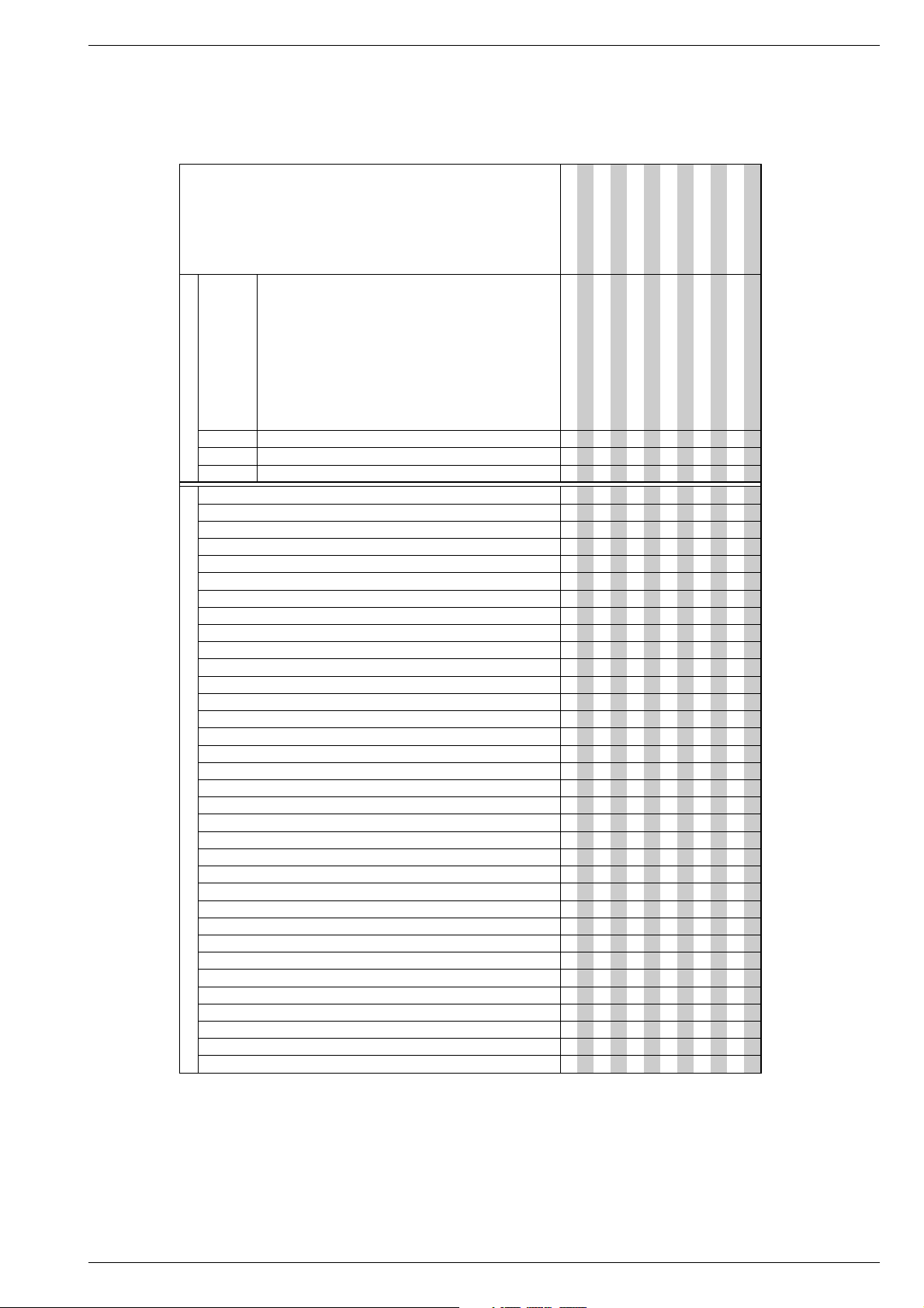
1.1 Gehäuseoberteil
– 2 Schrauben A herausdrehen (Fig. 1).
– Rastnase B lösen und Gehäuseoberteil abnehmen (Fig. 1).
1.2 Frontblende
– Jog-Shuttle nach vorne abziehen.
– 3 Rasthaken C (Fig. 2) auf der Geräteunterseite lösen.
– Frontblende an der Unterseite nach vorne klappen und an den
oberen Haken D (Fig. 3) aushängen.
Montagehinweis:
– Beim Aufstecken der Frontblende auf den Geräterahmen ist die
Cassettenklappe K (Fig. 4)
J
(Fig. 4)
befindet sich dadurch vor der Cassettenklappe in richtiger
Position.
zu öffnen. Der Cassettenklappenhebel
B
Service Instructions
1. Removing the Cabinet Parts
– Disconnect the set from the mains before opening it.
– Observe the safety instructions (see Safety Service Manual, part
number 720108000000)
1.1 Cabinet Top
– Undo 2 screws A (Fig. 1).
– Release the locking lug B then remove the cabinet top (Fig. 1).
1.2 Front Panel
– Pull the Jog Shuttle off to the front.
– Release 3 clamps C (Fig. 2) on the cabinet bottom.
– Turn the lower edge of the front panel towards the front and detach
the panel from the upper clamps D (Fig. 3).
Note on reassembly:
–
When plugging the front panel on the chassis frame the cassette door
K
(Fig. 4)
brought in this way into the correct position in front of the cassette
door.
must be opened. The cassette door lever J (Fig. 4)
C
is
A A
Fig. 1 Fig. 2
2. Ausbauhinweise
2.1 Laufwerk
– Frontblende abnehmen (Pkt. 1.2)
– 2 Schrauben E (Fig. 3) herausdrehen und Bügel F abnehmen.
– Steckverbindung zum Kombikopf (Fig. 3, CN3A01) lösen.
– 4 Schrauben G (Fig. 3) herausdrehen.
– Laufwerk waagerecht nach oben herausnehmen.
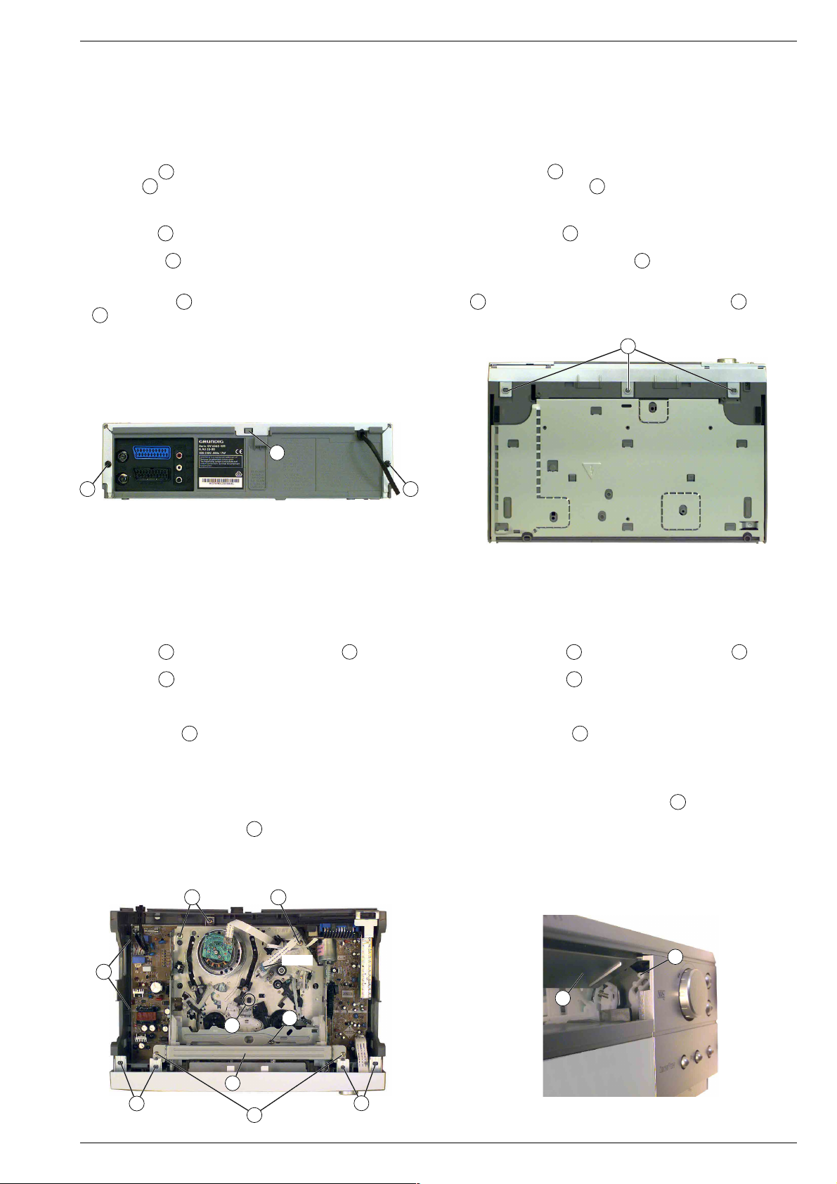
Montagehinweis:
– Der Einbau des Laufwerks muss in der Eject-Position erfolgen.
– Schneckenrad L des Lademotors so lange in Pfeilrichtung
(Fig. 5) drehen bis der Cassetten-Lift in Laufwerkstellung Eject
(Endanschlag) ist.
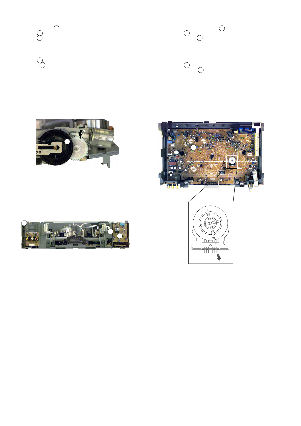
– Funktionswahlschalter SW601 (Fig. 7) in die Laufwerkposition
Eject drehen.
– Beim Aufsetzen des Laufwerks auf die Chassisplatte ist darauf zu
achten, dass die Sendediode LD601 für Bandanfang- und Bandende-Kennung durch das Loch H (Fig. 3) des Laufwerkes geführt
wird. Das Laufwerk muss leicht auf der Chassisplatte aufzusetzen
2. Disassembly Instructions
2.1 Drive Mechanism
– Remove the front panel (Point 1.2)
– Undo the 2 screws E (Fig. 3) then remove the bow F.
– Unplug the plug-in connector to the combi head (Fig. 3, CN3A01).
– Undo the 4 screws G (Fig. 3).
– Remove the drive mechanism horizontally to the top.
Note on reassembly:
– The drive mechanism must be reassembled in the Eject position.
– Turn the worm wheel L of the loading motor in direction of the arrow
(Fig. 5) until the cassette lift is in the Eject position (end stop).
– Turn the function selector SW601 (Fig. 7) in the Eject position.
– When placing the drive mechanism on the chassis board make sure
that the transmitter diode LD601 for the tape beginning and tape end
detection is passed through the hole H (Fig. 3) of the drive
mechanism. It must be possible to place the drive mechanism easily
on the chassis board to ensure that the plug-in connectors have a
good contact with the chassis board.
sein, damit die Steckverbindungen zur Chassisplatte richtig kontaktieren.
G
I
H
F
D
Fig. 3 Fig. 4
GRUNDIG Service 1 - 5
G
CN3A01
K
G
D
E
J
Page 6
Allgemeiner Teil / General Section GV 32…, GV 52…, GV 62…
2.2 Bedieneinheiten
– linke Bedieneinheit M(Fig. 6) nach oben herausziehen.
– Schraube N(Fig. 6) herausdrehen.
– Rastnase O(Fig. 6) lösen und rechte Bedieneinheit abnehmen.
2.3 Chassisplatte
– Laufwerk ausbauen (siehe Punkt 2.1).
– Bedieneinheiten ausbauen (siehe Punkt 2.2).
– Schraube P (Fig. 7) herausdrehen.
– Rastnasen I(Fig. 3) lösen, Chassisplatte hinten anheben und
nach oben vorsichtig herausnehmen.
– Chassisplatte nach oben vorsichtig herausnehmen.
Sicherheitshinweis
– Nach dem Herausnehmen der Chassisplatte ist die Lötseite des
Netzteils frei zugänglich und damit auch alle lebensgefährlichen
Spannungen. Im Servicefall immer Trenntrafo benutzen.
L
2.2 Keyboard Control Units
– Remove the left keyboard control unit M(Fig. 6) in upward direction.
– Undo the screw N(Fig. 6).
– Release the locking lug O(Fig. 6) then remove the right keyboard
control unit.
2.3 Chassis Board
– Remove the drive mechanism (Point 2.1).
– Remove the keyboard control units (Point 2.2).
– Undo the screw P(Fig. 7).
– Release the locking lugs I(Fig. 3) then lift the chassis board at the
rear side and carefully remove in upward direction.
Safety Precaution:
– After having removed the chassis board the solder side of the power
supply board is freely accessible and so are all voltages dangerous
to life. Do not fail to use an isolating transformer during repairs!
P
Fig. 5
M
O
N
3. Wichtige Masseverbindungen!
Beim Zusammenbau des Gerätes ist darauf zu achten, dass die
Masseverbindungen zwischen Gehäuseboden und Chassisplatte,
Buchsenplatte und Gehäuseoberteil, Chassisplatte und Laufwerk
sowie Gehäuseboden und Gehäuseoberteil gewährleistet sind.
4. Durchführen von Messungen
Bei Messungen mit dem Oszilloskop an Halbleitern sollten Sie nur
Tastköpfe mit 10:1 - Teiler verwenden. Außerdem ist zu beachten,
dass nach vorheriger Messung mit AC-Kopplung der Koppelkondensator des Oszilloskops aufgeladen sein kann. Durch die Entladung
über das Messobjekt können Bauteile beschädigt werden.
Fig. 7Fig. 6
3. WARNING: Chassis Connections!
When reassembling the machine make sure that the ground connections between the cabinet bottom and chassis board, socket board and
cabinet top, chassis board and drive mechanism, cabinet bottom and
cabinet top are in good order.
4. Carrying out Measurements
When making measurements on semi-conductors with an oscilloscope, ensure that the test probe is set to 10:1 dividing factor. If the
previous measurement was made on AC input, please note that the
coupling capacitor in the oscilloscope will be charged. Discharge via
the item being checked can damage the components.
5. Messwerte und Oszillogramme
Bei den in den Schaltplänen und Oszillogrammen angegebenen
Messwerten handelt es sich um Näherungswerte!
1 - 6 GRUNDIG Service
5. Measured Values and Oscillograms
The measured values given in the circuit diagrams and oscillograms
are approximates!
Page 7
GRUNDIG Service 1 - 7
6
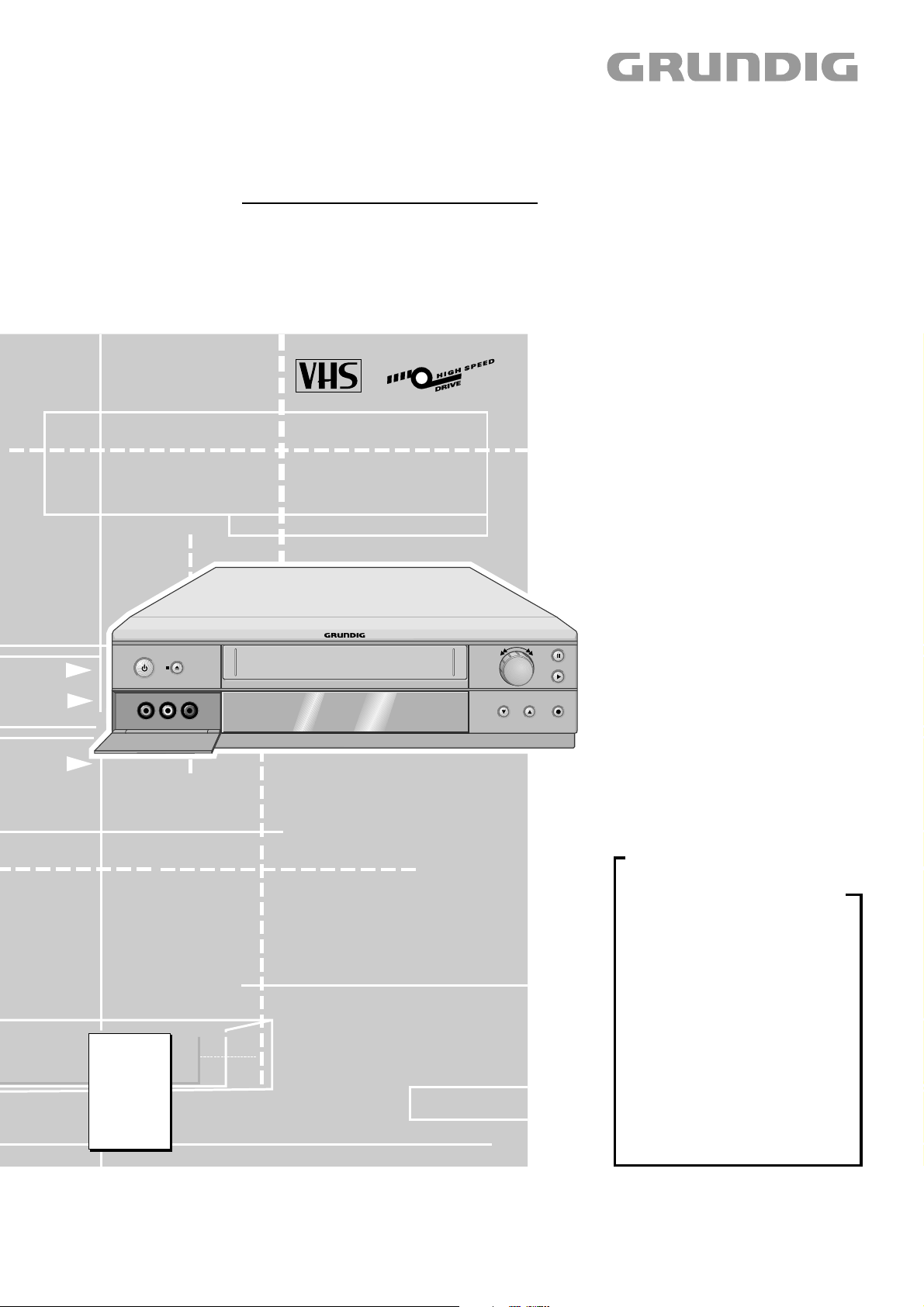
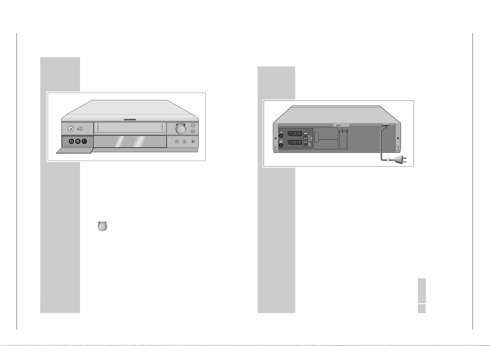
AUF EINEN BLICK
_________________________________________
Die Vorderseite des Videorecorders
A Schaltet den Videorecorder in Bereitschaft (Stand-
by, die Uhrzeit
– in verminderter Helligkeit
– wird
angezeigt) und ab (ECO-Betrieb, keine Anzeige).
■
N Beendet alle Laufwerkfunktionen;
schiebt die Cassette aus.
VIDEO IN Bildsignaleingang f
ür Camerarecorder (Buchse
hinter der Klappe).
L AUDIO IN R Tonsignaleingang links/rechts f
ür Camerarecorder
(Buchsen hinter der Klappe).
Drehknopf nach links drehen
– bei Wiedergabe:
Bildsuchlauf r
ückwärts;
nach Stopp: Band zur
ückspulen.
Drehknopf nach rechts drehen
– bei Wiedergabe:
Bildsuchlauf vorw
ärts;
nach Stopp: Band vorspulen.
II Pause bei Aufnahme, Standbild bei Wiedergabe.
ı
Startet die Wiedergabe.
*
P
Wählt Programme abw
ärts.
P Ü Wählt Programme aufw
ärts.
● Startet die Aufnahme.
VIDEO IN
L AUDIO IN R
P
DEUTSCH
7
AUF EINEN BLICK
_________________________________________________
Die Rückseite des Videorecorders
Ä
Antenneneingangsbuchse
(von der Hausantenne).
Ö Antennenausgangsbuchse
(zum Fernsehger
ät).
AV2 (DEC./EXT.) Euro/AV-Anschluss
(zu einem externen Ger
ät).
AV1 (EURO AV) Euro/AV-Anschluss
(zum Fernsehger
ät).
OUT/SORTIE Tonsignalausgang zur HiFi-Anlage.
R/D AUDIO L/G
ʐ
SAT-Steuerbuchse f
ür Grundig
VCR-SAT Modul und Satellitenreceiver.
Ü
Netzkabel zur Steckdose.
AV2 (DEC./EXT.)
AV1 (EURO AV)
Bedienhinweise
Dieses Kapitel enth
hende Informationen entnehmen Sie bitte der ger
ält Auszüge aus der Bedienungsanleitung. Weiterge-
ätespezifischen Bedie-
nungsanleitung, deren Materialnummer Sie in der entsprechenden Ersatzteilliste finden.
GV 32…, GV 52…, GV 62… Allgemeiner Teil / General Section
Page 8
1 - 8 GRUNDIG Service
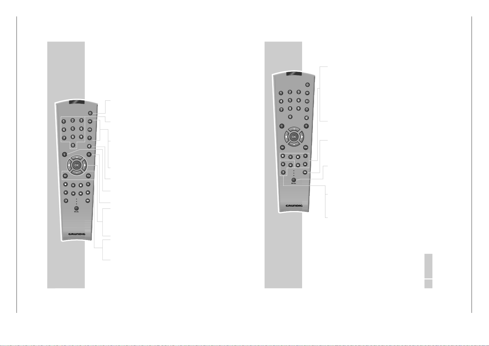
8
AUF EINEN BLICK
_________________________________________________
Die Fernbedienung
Hier finden Sie die wichtigsten Funktionen der Fernbedienung.
Die Bedienung entnehmen Sie bitte dem jeweiligen Kapitel
dieser Bedienungsanleitung.
Richten Sie die Fernbedienung auf den Videorecorder.
Ǽ
Einmal dr
ücken, schaltet den Videorecorder in
Bereitschaft (Stand-by);
noch einmal dr
ücken schaltet den Videorecor-
der ab (ECO-Betrieb).
1 … 0 Schalten den Videorecorder aus Stand-by ein;
Ziffern-Tasten f
ür verschiedene Eingaben,
» 0 « wählt Programmpl
ätze »
A I
«, »
A2
«
oder »
CV
«.
Digital FX Taste ohne Funktion.
OSD Zum Ein-/Ausschalten der Anzeigen f
ür Funktion und Spielzeit auf dem Bildschirm des Fernsehgerätes.
Clear Löscht Daten, aktiviert Eingaben, setzt die Spiel-
zeitanzeige auf
»
0:00:00
«.
d
Schaltet den Ton eines Grundig Fernsehger
ätes
ab bzw. wieder an.
i Schaltet auf das Hauptmen
ü und zur
ück auf das
Fernsehbild.
Timer/SV Eröffnet die ShowView-Aufnahme.
+ – Wählen Programme,
»
+
« aufwärts, »
– «
abwärts;
wählen in den Men
üs verschiedene Funktionen.
OK Ruft Daten auf, best
ätigt und speichert Daten.
® †
Wählen in den Men
üs verschiedene Funktionen.
SP/LP Schaltet wechselweise auf Langspiel-Betrieb und
Standardspiel-Betrieb (Spielzeit vor der Aufnahme w
ählen).
Timer on Kurzes Dr
ücken aktiviert die TIMER-Aufnahme;
längeres Dr
ücken (ca. 3 Sekunden) deaktiviert
die TIMER-Aufnahme.
Tele Pilot 93 V
Digital FX
OSD
Clear
Timer/SV
Timer on
SP/LP
Dub
Index
Audio
Monitor
VCR1
TV
VCR2
DEUTSCH
9
AUF EINEN BLICK
_________________________________________________
● Startet die Aufnahme.
II Pause bei Aufnahme, Standbild bei Wiedergabe.
■
Beendet alle Laufwerkfunktionen und schaltet den
Videorecorder in
„Stopp“.
ı
Startet die Wiedergabe.
ľľ
Bildsuchlauf r
ückwärts bei Wiedergabe;
Band rückspulen in
„Stopp“;
wählt die Richtung der INDEX-Suchfunktion.
ıı
Bildsuchlauf vorw
ärts bei Wiedergabe;
Band vorspulen in
„Stopp“;
wählt die Richtung der INDEX-Suchfunktion und
die Funktion Ziellauf.
Monitor Schaltet die Schaltspannung der EURO-AV-Buchse
ab.
Dadurch wird am Fernsehger
ät der Programm-
platz AV abgeschaltet und der vorher gew
ählte
Programmplatz des Fernsehger
ätes ist zu sehen
MODE Schaltet die Fernbedienung von der Bedienung
Ihres Videorecorders (Anzeige
» VCR 1«) um auf
die Bedienung eines Fernsehger
ätes (Anzeige
» TV«, die Möglichkeiten sind auf Seite 62
beschrieben) oder die Bedienung eines zweiten
Videorecorders (Anzeige
» VCR 2«).
Dub Wählt die Funktion Nachvertonen (Dubbing);
schaltet zu den Men
üs einen blauen Hindergrund.
Index Aktiviert die INDEX-Suchfunktion.
Audio Zur Tonspurwahl bei Aufnahme und Wiedergabe.
Tele Pilot 93 V
Digital FX
OSD
Clear
Timer/SV
Timer on
SP/LP
Dub
Index
Audio
Monitor
VCR1
TV
VCR2
Allgemeiner Teil / General Section GV 32…, GV 52…, GV 62…
Page 9
GRUNDIG Service 1 - 9
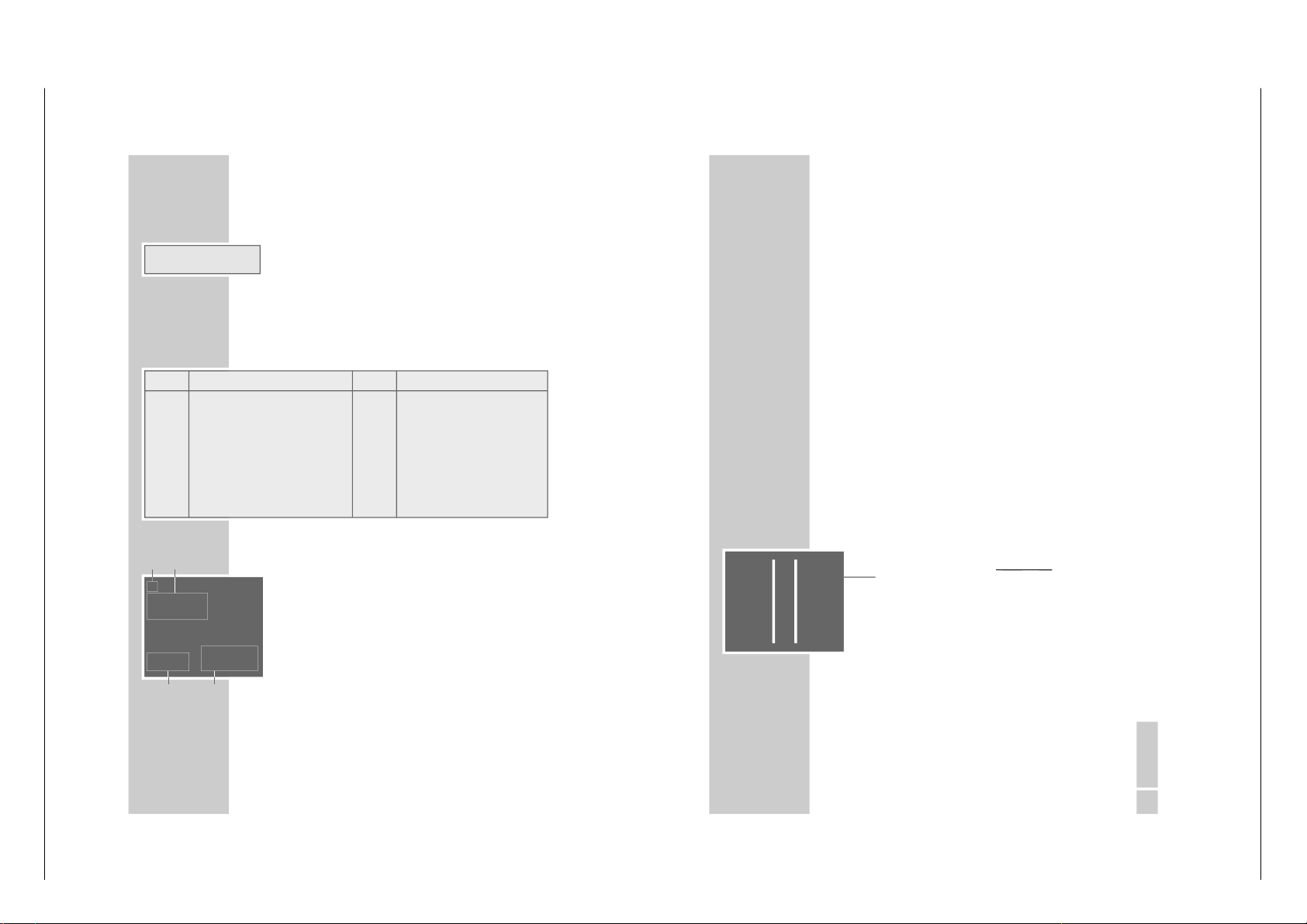
AUF EINEN BLICK
_________________________________________________
10
Die Anzeige am Videorecorder
ß
Cassette eingelegt.
ı
Wiedergabe.
VIDEO PIN-8 Schaltspannung eingeschaltet.
Ȅ
leuchtet, wenn ein TIMER programmiert ist;
blinkt, wenn ein TIMER programmiert aber nicht
aktiviert ist.
˲
Aufnahme.
STEREO Stereo-/ oder Zweikanaltonsendung.
-O
:
OO
:
OO
Zeigt verschiedene Funktionen und Zust
ände:
Die OSD-Anzeige am Fernsehger
ät
1
ı
Wiedergabe
ıı
Bildsuchlauf vorw
ärts oder Band vorspulen
ľľ
Bildsuchlauf r
ückwärts oder Band r
ückspulen
II Standbild
II
ı
Zeitlupe oder n
ächstes Standbild
● Aufnahme
● II Aufnahme-Pause
2
ACC PLUS AUTO Bildschärfe
END OF TAPE Bandende erreicht
A.DUB Dubbing-Funktion
SP LP Standard- oder Langspielzeit
INTRO-SCAN: Such-Funktion
INDEX-SEARCH: Such-Funktion
GOTO 0: 00:00 Ziellauf
3
12:33 Uhrzeit
21/06 02 Datum
4
USED abgelaufene Spielzeit
REM restliche Spielzeit
2:26.12 Bandanzeige in Stunden, Minuten
und Sekunden
Anzeige Funktion Anzeige Funktion
Auto Automatische Spurlage (Auto Tracking); PLAY Wiedergabe;
ASr Aufnahme, gesteuert durch die Schalt-. PSE Aufnahmepause;
uhr eines Satellitenreceivers; r E Band zur
ückspulen;
CASS keine Cassette eingelegt; rEC Aufnahme;
Cant Andauernde-Wiedergabe; SECU Kindersicherung aktiv;
dub Nachvertonen; StILL Standbild w
ährend der Wiedergabe;
FF Band vorspulen; SLO Zeitlupe;
FSF Bildsuchlauf vorw
ärts;
StOP Wiedergabe-/Aufnahmestopp;
FSr Bildsuchlauf r
ückwärts;
ı
ACC PLUS AUTO
SP
USED 2:55
12:33 REM 1:05
21/06 02 2:26.12
1
3
4
2
ß
Ȅ
ı
˲
VIDEO STEREO
-8
:
88
:
88
DEUTSCH
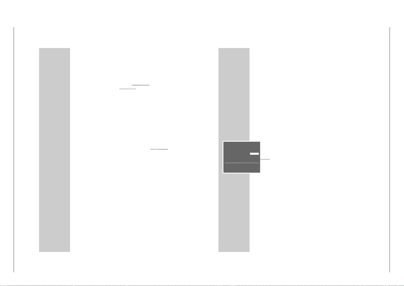
17
Videorecorder und Fernsehger
ät
anpassen
Diese Einstellung ist nicht notwendig, wenn der Videorecorder
und das Fernsehger
ät mit einem EURO-AV-Kabel verbunden
sind.
1
Fernsehger
ät einschalten.
2
Am Fernsehger
ät den Programmplatz
»AV « für Recorder-
Wiedergabe
über das Antennenkabel w
ählen.
3
Am Fernsehger
ät im UHF-Bereich, zwischen Kanal 21 und
Kanal 69, einen
„freien“ Kanal suchen, der nicht mit einem
Fernseh-Programm belegt ist (nur Bildflimmern am Bildschirm und Tonrauschen).
– Bei vielen Fernsehger
äten wird die Kanalzahl angezeigt.
4
Kanalzahl des
„freien“ Kanals am Fernsehger
ät speichern.
Hinweis:
Nach dem erstmaligen Einschalten des Recorders blinkt in
der Anzeige des Recorders
»
Auto
«. An der Fernbedienung
solange
»
i« drücken, bis die Anzeige
»
--:--« erscheint.
5
Videorecorder mit
»
Ǽ
« in Stand-by schalten, danach
»
i«
länger drücken.
– Anzeige am Videorecorder, zum Beispiel
»
CH 21
« .
6
Kanal mit
»
* P Ü « am V
ideor
ecor
der
einstellen.
– Am Bildschirm des Fernsehger
ätes erscheint das
„Test-
bild“ des Videorecorders.
7
Ist die Bildqualit
ät des „Testbildes
“ in Ordnung, Einstellung
mit »OK « beenden.
– Der Videorecorder schaltet auf Stand-by.
Hinweise:
Ist die Qualit
ät des „Testbildes
“ nicht zufriedenstellend oder
die Qualit
ät eines oder mehrerer Fernseh-Programme am
Fernsehger
ät hat sich verschlechtert, dann m
üssen Sie am
Fernsehger
ät einen anderen
„freien“ Kanal suchen, dazu
die Einstellungen der Pkt. 3 bis 7 wiederholen.
Sind Videorecorder und Fernsehger
ät mit einem EURO-AVKabel verbunden, schalten Sie den Sender des Videorecorders ab, siehe Kapitel
„Sender des Videorecorders ab-/ein-
schalten
”, auf Seite 52.
EINSTELLUNGEN
____________________________________________
GV 32…, GV 52…, GV 62… Allgemeiner Teil / General Section
Page 10

1 - 10 GRUNDIG Service
22
WIEDERGABE
__________________________________________________
Vorbereiten
Fernsehger
ät einschalten.
Am Fernsehger
ät den Programmplatz
»AV « für den Video-
recorder w
ählen.
Bespielte Cassette
– mit dem Fenster nach oben
– soweit in das
Cassettenfach schieben, bis sie automatisch eingezogen wird.
– Anzeige am Videorecorder:
»« (Cassettensymbol).
Hinweis:
Wird eine Cassette mit ausgebrochener L
öschsicherung in
den Videorecorder geschoben, startet automatisch die
Wiedergabe.
Grundfunktionen der Wiedergabe
1
Wiedergabe mit
»
ı
« starten.
– Anzeige am Videorecorder:
»
PLAY«, am Bildschirm des
Fernsehger
ätes werden kurz Informationen eingeblendet.
– Für kurze Zeit blinkt in der Anzeige am Videorecorder
» Auto«, in dieser Zeit wird automatisch die Spurlage des
Bandes eingestellt.
Hinweis:
Ist der Videorecorder an ein Fernsehger
ät mit Megalogic-Funktionen angeschlossen, schaltet sich das Fernsehgerät nach dem Starten der Wiedergabe aus der
Betriebsstellung Standby ein und schaltet automatisch
auf den Programmplatz
»AV «.
2
Auf Standbild/Pause mit
»
II« schalten.
Mehrmaliges Dr
ücken schaltet das Standbild schrittweise
weiter.
3
Bildsuchlauf r
ückwärts/vorw
ärts, dazu w
ährend der
Wiedergabe
»
ľľ
« oder »
ıı
« der Fernbedienung
drücken.
Mehrmaliges Dr
ücken schaltet auf verschiedene Wieder-
gabe-Geschwindigkeiten;
oder
während der Wiedergabe Drehknopf am Ger
ät nach links
oder rechts drehen.
4
Wiedergabe mit
»
■ « beenden.
5
Cassette ausschieben mit
»
■
ə
« am V
ideor
ecor
der
.
Hinweis:
Ihr Videorecorder schaltet automatisch in den ECOBetrieb wenn die Funktion Standbild l
änger als 5 Minu-
ten gewählt ist oder der Videorecorder l
änger als 1
Minute auf
„STOPP“ steht.
ß
ß
ı
STEREO
St ILL
ß
ı
STEREO
FS r
ß
STEREO
St OP
ß
ı
STEREO
PL AY
ß
ı
STEREO
Au t o
DEUTSCH
23
WIEDERGABE
________________________________________________________
Zusatzfunktionen der Wiedergabe
Informationen aufrufen
1
Mit »OSD« Informationen aufrufen.
– Anzeige am Bildschirm des Fernsehger
ätes:
der Programmplatz;
das Datum und die Uhrzeit;
und nach kurzer Laufzeit:
»USED« die abgelaufene Spielzeit des Bandes;
»REM« die restliche Spielzeit;
»0:00:00
« die Bandanzeige in Stunden, Minuten und
Sekunden.
– In der Anzeige am Videorecorder k
önnen die Informatio-
nen nacheinander mit
»
OK« eingeblendet werden.
– Die Bandanzeige kann mit
»
Clear« auf »
0:00:00
«
gesetzt werden.
2
Informationen mit
»
OSD« abschalten.
Cassette vor-/zur
ückspulen
1
Videorecorder mit
»
■ « auf Stopp schalten.
2
Zurückspulen mit
»
ľľ
«, vorspulen mit
»
ıı
« der Fernbedienung;
oder Drehknopf am Ger
ät nach links oder rechts drehen.
Zweifache Wiedergabegeschwindigkeit
1
Während der Wiedergabe
»
ı
« drücken.
– Die Anzeige
»
ı
« blinkt.
2
Zurück zur Wiedergabe, dazu nocheinmal
»
ı
« drücken.
Zeitlupe
1
Während des Standbildes (Wiedergabe/Pause)
»
II« län-
ger drücken.
2
Zeitlupengeschwindigkeit mit
»
®
« oder »
†
« verändern.
3
Zurück zur Wiedergabe, dazu
»
ı
« drücken.
Standbilder schrittweise weiterschalten
1
Während des Standbildes (Wiedergabe/Pause)
»
II«
wiederholt dr
ücken.
2
Zurück zur Wiedergabe, dazu
»
ı
« drücken.
ß
ı
STEREO
0
:
00
:
56
ß
ı
STEREO
0
:
00
:
00
ß
ı
STEREO
rE
ß
ı
STEREO
PL AY
ß
ı
STEREO
SL O
ß
ı
STEREO
St ILL
Allgemeiner Teil / General Section GV 32…, GV 52…, GV 62…
Page 11
GRUNDIG Service 1 - 11
24
WIEDERGABE
________________________________________________________
Bildverbesserung des Standbildes/ der
Zeitlupe
1
Während des Standbildes/der Zeitlupe (Wiedergabe/
Pause) mit
»
*
P
Ü « am V
ideor
ecor
der
oder mit
»
+«
oder »–« an der Fer
nbedienun
g das Bild nach subjektiv
bestem Eindruck einstellen.
2
Zurück zur Wiedergabe, dazu
»
ı
« drücken.
Hinweis:
Die Funktion Standbild schaltet der Videorecorder nach
einiger Zeit automatisch ab.
Bildstörungen (St
örstreifen) beseitigen
1
Während der Wiedergabe mit
»
+« oder » –« das Bild
nach subjektiv bestem Eindruck einstellen.
– Diese Einstellung bleibt bis zur Entnahme der Cassette
erhalten.
2
Gleichzeitiges Dr
ücken von
»
*
P
Ü « am V
ideor
ecor
der
schaltet auf
„mittlere” Spurlage.
Bildsch
ärfe einstellen (ACC Plus)
Die Bildsch
ärfe kann nach Ihrem individuellen Eindruck einge-
stellt werden.
1
Während der Wiedergabe das Bild mit
»
®
« (weicher)
oder »
†
« (schärfer einstellen).
2
Zurück zur Mittenstellung, dazu
»
Clear« drücken, solange
das Men
ü eingeblendet wird.
Wiedergabe von NTSC-Aufzeichnungen
Bei der Wiedergabe von NTSC-Aufzeichnungen (Sendungen
nach der amerikanischen Fernsehnorm) schaltet der Videorecorder automatisch auf dieses System.
Hinweise:
Bei NTSC-Wiedergabe ist kein einwandfreies Standbild
möglich.
Bei NTSC-Langspiel-Wiedergabe k
önnen Bildst
örungen
auftreten.
26
WIEDERGABE
________________________________________________________
Dauerlauf-Wiedergabe
Bei dieser Funktion wird wird der Bandinhalt vom Bandanfang
bis zur Bandpositon
»
0:00:00
« wiedergegeben. Dort spult der
Videorecorder die Cassette automatisch an den Anfang zur
ück
und beginnt erneut mit der Wiedergabe.
Dauerlauf-Wiedergabe aktivieren
1
Wiedergabe mit
»
ı
« starten und Bandanzeige mit
» OSD« einblenden.
2
An der gew
ünschten Bandstelle die Bandanzeige mit
» Clear« auf »
0:00:00
« stellen.
3
Hauptmen
ü mit »
i« aufrufen.
– Das Hauptmen
ü erscheint.
4
Zeile » SERVICE
« mit »
+« oder »– « wählen und mit
» OK « aktivieren.
– Das Men
ü » SERVICE
« erscheint.
5
Zeile » CONTINUOS-PLAY
« mit »
+« oder »– « wählen.
6
Dauerlauf-Wiedergabe mit
»
®
« oder »
†
« aktivieren
(Anzeige
» EIN«) und mit
»
OK « bestätigen.
– Das Band wird an den Anfang gespult, dort beginnt die
Wiedergabe. Die Tasten am Ger
ät und an der Fernbedie-
nung (Ausnahme: Taste
»
i«) haben w
ährend der Dauer-
lauf-Wiedergabe keine Funktion.
Dauerlauf-Wiedergabe abschalten
1
Menü » SERVICE
« mit »
i« aufrufen.
2
Dauerlauf-Wiedergabe mit
»
®
« oder »
†
« abschalten
(Anzeige
» AUS«) und mit
»
OK « bestätigen.
SERVICE
PIN8-STEUERUNG AUS
KINDERSICHERUNG - - - - CASSETTEN-L
ÄNGE E180
■
➔
CONTINUOS-PLAY AUS
HF-KANAL C 21
ATS-NEUSTART AUS
ZUSATZ-MEN
Ü - - - -
ɶʺ
:WÄHLEN
<>
:ÄNDERN
OK :EINGABE INFO:ENDE
GV 32…, GV 52…, GV 62… Allgemeiner Teil / General Section
Page 12

1 - 12 GRUNDIG Service
DEUTSCH
29
AUFNAHME
– SOFORT
______________________________
Fernseh-Programme von der Antenne oder
dem Kabelanschluss aufnehmen
Vorbereiten
Fernsehger
ät einschalten.
Am Fernsehger
ät den Programmplatz
»AV « für den Videore-
corder w
ählen.
Cassette mit ausreichender Spieldauer und intakter Lasche
(Cassette nicht gesperrt) soweit in das Cassettenfach schieben,
bis sie automatisch eingezogen wird.
– Anzeige am Recorder:
»« (Cassettensymbol).
Bedienung
1
Wenn gew
ünscht, Langspiel-Betrieb mit
»
SP/LP« wählen.
– Anzeige am Videorecoder
»
LP
«.
2
Vor der Aufnahme das gew
ünschte Fernseh-Programm mit
»+« » –« oder
»* P Ü « oder
»0…9« wählen.
3
Aufnahme starten, dazu
»
●« länger drücken.
Hinweis:
Ist der Videorecorder an ein Fernsehger
ät mit Megalogic-
Funktionen angeschlossen, kann mit
»
●« das Fernseh-
Programm, das am Bildschirm des Fernsehger
ätes zu sehen
ist, aufgezeichnet werden. Der Programmplatz muss am
Videorecorder nicht gew
ählt werden.
4
Aufnahmepause mit
»
II« wählen.
Hinweis:
Während Aufnahmepause kann auf ein anderes FernsehProgramm umgeschaltet werden.
5
Aufnahme mit
»
■ « beenden.
6
Band zur
ückspulen mit
»
ľľ
«, Band vorspulen mit
»
ıı
«
der Fernbedienung;
oder
Drehknopf am Ger
ät nach links oder rechts drehen.
7
Cassette ausschieben mit
»
■
ə
« am V
ideor
ecor
der
.
ß
ß
LP
ß
STEREO
Pr 3
ß
˲
STEREO
rE c
ß
˲
STEREO
PS E
ß
STEREO
St OP
AUFNAHME
– SOFORT
________________________________________
30
Fernseh-Programme vom Satellitenreceiver aufnehmen
Vorbereiten
Fernsehger
ät einschalten.
Am Fernsehger
ät den Programmplatz
»AV « für den Videore-
corder w
ählen.
Cassette mit ausreichender Spieldauer und intakter Lasche
(Cassette nicht gesperrt) soweit in das Cassettenfach schieben,
bis sie automatisch eingezogen wird.
– Anzeige am Recorder:
»« (Cassettensymbol).
Bedienung
1
Satellitenreceiver einschalten.
2
Am Satellitenreceiver gew
ünschtes Satelliten-Programm
wählen.
3
Am Videorecorder den Programmplatz
»AV « wählen, dazu
» 0 « drücken und mit
»
–« Programmplatz w
ählen.
– Anzeige:
»
A2
«.
4
Aufnahme starten, dazu
»
●« länger drücken.
5
Aufnahme mit
»
■ « beenden.
Abschaltzeit eingeben
1
Während der Aufnahme mit
»
●« die gew
ünschte
Abschaltzeit in 30-Minuten-Schritten eingeben;
oder
mit »+« oder » –« Abschaltzeit in 1-Minuten-Schritten eingeben.
– Die Ausschaltzeit ist nur am Bildschirm des Fernsehger
ä-
tes zu sehen.
– Am Videorecorder leuchtet die TIMER-Anzeige
»
Ȅ
«, der
Videorecorder schaltet bei Erreichen dieser Zeit automatisch ab.
ß
ß
Ȅ
˲
STEREO
I6
:
00
ß
A2
ß
Ȅ
˲
STEREO
I6
:
30
ß
Ȅ
˲
STEREO
I7
:
00
Allgemeiner Teil / General Section GV 32…, GV 52…, GV 62…
Page 13

GRUNDIG Service 1 - 13
48
SONDEREINSTELLUNGEN
_________________________
Fernseh-Programme sortieren, l
öschen
und Namen der Fernseh-Programme
ändern
Hinweis:
Ist der Videorecorder an ein Fernsehger
ät mit MegalogicFunktionen angeschlossen, sind die Einstellungen auf den
Seiten 48 bis 54 nicht m
öglich.
Vorbereiten
Fernsehger
ät einschalten.
Am Fernsehger
ät den Programmplatz
»AV « für den Video-
recorder w
ählen.
Hauptmen
ü aufrufen
1
Hauptmen
ü mit »
i« aufrufen.
– Das Hauptmen
ü erscheint.
2
Zeile » GRUNDEINSTELLUNG
« mit »
+« oder »– « wählen
und mit
»
OK « aktivieren.
– Das Men
ü »GRUNDEINSTELLUNG
« erscheint.
3
Zeile »SENDER SORTIEREN
« mit »
+« oder »– « wählen
und mit
»
OK « aktivieren.
– Das Men
ü »SENDER SORTIEREN
« erscheint.
Hinweise:
Wählen Sie aus dem Men
ü »SENDER SORTIEREN
« die
gewünschte Funktion, die weitere Bedienung entnehmen Sie
bitte den folgenden Kapiteln, jeweils ab Pkt. 1.
Im Hintergrund des Men
üs erscheint das aktuelle Fernseh-
Programm. Wenn der Text im Men
ü dadurch gest
ört ist,
» Dub« drücken, das Men
ü wird blau hinterlegt.
Fernseh-Programme sortieren
1
Zeile » BEWEGEN
« mit »
OK « aktivieren.
– Das Men
ü » BEWEGEN
« erscheint.
2
Gewünschtes Fernseh-Programm, das getauscht werden
soll, mit
»
+ –
® †
« wählen und mit
»
OK « markieren.
3
Programmplatz, mit dem das markierte Fernseh-Programm
getauscht werden soll, mit
»
+ –
® †
« wählen und mit
» OK « bestätigen.
4
Einstellung mit
»
i« beenden.
GRUNDEINSTELLUNGEN
SENDEREINSTELLUNG
SENDER SORTIEREN
UHR
SPRACHE
ɶʺ
:WÄHLEN
OK :EINGABE INFO:ENDE
SENDER SORTIEREN
BEWEGEN
LÖSCHEN
NAME
ɶʺ
:WÄHLEN
OK :EINGABE INFO:ENDE
DEUTSCH
49
SONDEREINSTELLUNGEN
____________________________________
Fernseh-Programme aus der Sendertabelle
löschen
1
Zeile »LÖSCHEN« mit »
+« oder »– « wählen und mit
» OK « aktivieren.
– Das Men
ü » LÖSCHEN« erscheint.
2
Fernseh-Programm, das gel
öscht werden soll, mit
»
+ –
® †
« wählen und mit
»
OK« markieren.
3
Fernseh-Programm mit
»
Clear« löschen.
4
Einstellung mit
»
i« beenden.
Namen der Fernseh-Programme eingeben
1
Zeile » NAME« mit »
+« oder »– « wählen und mit
»
OK «
aktivieren.
– Das Men
ü »NAME« erscheint.
2
Programmplatz, f
ür den ein Namen eingegeben werden
soll, mit
»
+ –
® †
« wählen und mit
»
OK « aktivieren.
3
Zeichen mit
»
+« oder »– « eingeben, n
ächste Stelle mit
»
®
« oder »
†
« wählen und Eingaben f
ür die restlichen
Stellen (max. 5 Stellen) wiederholen.
4
Einstellung mit
»
OK « speichern.
5
Einstellung mit
»
i« beenden.
Fernseh-Programme neu einstellen
Der ATS-Suchlauf kann neu durchgef
ührt werden, dies kann
bei einem Wohnortwechsel hilfreich sein. Beachten Sie, alle
gespeicherten Fernseh-Programme werden gel
öscht.
1
Hauptmen
ü mit »
i« aufrufen.
2
Zeile » SERVICE
« mit »
+« oder »– « wählen und mit
» OK « aktivieren.
3
Zeile » ATS-NEUSTART
« mit »
+« oder »– « wählen.
4
Anzeige
» START« mit »
®
« oder »
†
« wählen und mit
» OK « bestätigen.
– Die weitere Bedienung gleicht derer im Kapitel
„Automa-
tische Einstellung
”, Seite 20, ab Pkt.
2.
SENDER SORTIEREN
BEWEGEN
LÖSCHEN
NAME
ɶʺ
:WÄHLEN
OK :EINGABE INFO:ENDE
SENDER SORTIEREN
BEWEGEN
LÖSCHEN
NAME
ɶʺ
:WÄHLEN
OK :EINGABE INFO:ENDE
SERVICE
PIN8-STEUERUNG AUS
KINDERSICHERUNG - - - - CASSETTEN-L
ÄNGE E180
CONTINUOS-PLAY AUS
HF-KANAL C21
■
➔
ATS-NEUSTART START
ZUSATZ-MEN
Ü - - - -
ɶʺ
:WÄHLEN
<>
:ÄNDERN
OK :EINGABE INFO:ENDE
GV 32…, GV 52…, GV 62… Allgemeiner Teil / General Section
Page 14

1 - 14 GRUNDIG Service
50
SONDEREINSTELLUNGEN
____________________________________
Fernseh-Programme
„auslassen
”
Diese Funktion aktivieren Sie, wenn Sie beim schrittweisen
Weiterschalten der Programmpl
ätze mit »
+« oder »– « einen
oder mehrere Programmpl
ätze überspringen wollen.
Die Programmpl
ätze können jedoch mit
»
0 … 9« weiterhin
angewählt werden.
Vorbereiten
Fernsehger
ät einschalten.
Am Fernsehger
ät den Programmplatz
»AV « für den Videore-
corder w
ählen.
Einstellung
1
Hauptmen
ü mit »
i« aufrufen.
2
Zeile » GRUNDEINSTELLUNG
« mit »
+« oder »– « wählen
und mit
»
OK « aktivieren.
3
Zeile » SENDEREINSTELLUNG
« aktivieren, dazu zweimal
» OK « drücken.
– Am Bildschirm erscheint das Men
ü zur Sendereinstellung,
die Zeile
»PROGRAMM
« ist markiert.
4
Mit »
®
« oder »
†
« oder » 0 … 9 « den Programmplatz
wählen, der
„ausgelassen
” werden soll.
5
Zeile » AUSLASSEN
« mit »
+« oder »– « wählen.
6
» EIN« mit »
®
« wählen.
7
Einstellung f
ür diesen Programmplatz mit
»
OK « speichern.
8
Einstellung mit
»
i« beenden.
Hinweis:
Damit die Programmpl
ätze wieder angew
ählt werden k
ön-
nen, Einstellung wiederholen und in Pkt. 6 »AUS« mit
»
†
« wählen.
MENÜ
TIMER
MODE
GRUNDEINSTELLUNG
SERVICE
ɶʺ
:WÄHLEN
OK :EINGABE INFO:ENDE
■
➔
PROGRAMM ARD 01
KANAL C06
QUELLE C/S/E
FEINEINSTELLUNG
‹›
AUSLASSEN AUS
COLOR AUTO
DECODER AUS
0-9 :DATEN
ɶʺ
:WÄHLEN
<>
:ÄNDERN
OK :EINGABE INFO :ENDE
PROGRAMM ARD 01
KANAL C06
QUELLE C/S/E
FEINEINSTELLUNG
‹›
■
➔
AUSLASSEN EIN EIN
COLOR AUTO
DECODER AUS
ɶʺ
:WÄHLEN
<>
:ÄNDERN
OK :EINGABE INFO: ENDE
DEUTSCH
51
SONDEREINSTELLUNGEN
____________________________________
Neue Fernseh-Programme von der
Antenne oder der Kabelanlage einstellen
Vorbereiten
Fernsehger
ät einschalten.
Am Fernsehger
ät den Programmplatz
»AV « für den Videore-
corder w
ählen.
Einstellung
1
Hauptmen
ü mit »
i« aufrufen.
2
Zeile » GRUNDEINSTELLUNG
« mit »
+« oder »– « wählen
und mit
» OK « aktivieren.
3
Zeile » SENDEREINSTELLUNG
« aktivieren, dazu zweimal
» OK « drücken.
– Am Bildschirm erscheint das Men
ü zur Sendereinstellung,
die Zeile
»PROGRAMM
« ist markiert.
Hinweis:
Wenn das aktuelle Fernseh-Programm die Einstellung st
ört,
» Dub« drücken, das Men
ü wird blau hinterlegt.
4
Mit »
®
« oder »
†
« oder »
0 … 9« den gew
ünschten
Programmplatz w
ählen, auf dem das neue Fernseh-Pro-
gramm gespeichert werden soll.
5
Zeile » COLOR« mit »
+« oder »– « wählen und das
benötigte Fernsehsystem (
» PAL «, »MESECAM
« oder
» AUTO«) mit »
®
« oder »
†
« wählen.
6
Zeile » KANAL« mit »
+« oder »– « wählen.
Umschalten von normalen Kan
älen (Anzeige:
»C«) auf
Sonder-/Hyperbandkan
äle (Anzeige:
»S«) oder auf Spezial-
kanäle (Anzeige:
»E«) und wieder zur
ück mit »
Monitor«.
7
Kanalzahl des Fernseh-Programmes mit
»
0 … 9« zwei-
stellig eingeben;
oder
Suchlauf mit
»
®
« oder »
†
« starten.
8
Fernseh-Programm (wenn n
ötig) feinabstimmen, dazu mit
»+« oder »
–« die Zeile
»FEINEINSTELLUNG
« anwählen
und mit
»
®
« oder »
†
« verändern.
9
Zeile »AUSLASSEN
« mit »
+« oder »– « wählen und mit
»
†
« »AUS« wählen.
■
➔
PROGRAMM SKY 20
KANAL C 46
QUELLE C/S/E
FEINEINSTELLUNG
< >
AUSLASSEN AUS
COLOR AUTO
DECODER AUS
0-9 :DATEN
ɶʺ
:WÄHLEN
<>
:ÄNDERN
OK :EINGABE INFO :ENDE
■
➔
PROGRAMM ----- 21
KANAL C 00
QUELLE C/S/E
FEINEINSTELLUNG
< >
AUSLASSEN AUS
COLOR AUTO
DECODER AUS
0-9 :DATEN
ɶʺ
:WÄHLEN
<>
:ÄNDERN
OK :EINGABE INFO :ENDE
PROGRAMM ----- 21
■
➔
KANAL C 49
QUELLE C/S/E
FEINEINSTELLUNG
< >
AUSLASSEN AUS
COLOR AUTO
DECODER AUS
MON.
:C/S/E 0-9 :DATEN
ɶʺ
:WÄHLEN
<>
:ÄNDERN
OK :EINGABE INFO :ENDE
Allgemeiner Teil / General Section GV 32…, GV 52…, GV 62…
Page 15
GRUNDIG Service 1 - 15
52
10
Einstellung f
ür diesen Programmplatz mit
»
OK «
speichern.
– Der Cursor springt auf die Zeile
»PROGRAMM
«, der
nächste Programmplatz wird angezeigt.
Hinweis:
Zum Einstellen von weiteren Fernseh-Programmen die
Pkt. 4 bis 10 wiederholen.
11
Einstellung mit
»
i« beenden.
Sender des Videorecorders
aus-/einschalten
Wenn viele Fernsehsender angeboten werden, die Ihr Videorecorder im UHF-Bereich zwischen Kanal 21 und 69 empf
ängt,
kann es zu Bildst
örungen im Recorder-Betrieb kommen.
Wird der Sender des Videorecorders ausgeschaltet, m
üssen
Videorecorder und Fernsehger
ät mit einem EURO-AV-Kabel
verbunden sein (siehe Kapitel
„Anschlie
ßen und Vorbereiten
“
auf Seite 12, 13 oder 15).
Sender des Videorecorders ausschalten
1
Hauptmen
ü mit »
i« aufrufen.
2
Zeile » SERVICE
« mit »
+« oder »– « wählen und mit
» OK « aktivieren.
– Das Men
ü » SERVICE
« erscheint.
3
Zeile » HF-KANAL
« mit »
+« oder »– « wählen.
4
Sender des Videorecorders mit
»
®
« oder »
†
« ausschal-
ten (Anzeige
» AUS«) und mit
»
OK « bestätigen.
Sender des Videorecorders einschalten
1
Hauptmen
ü mit »
i« aufrufen.
2
Zeile » SERVICE
« mit »
+« oder »– « wählen und mit
» OK « aktivieren.
– Das Men
ü » SERVICE
« erscheint.
3
Zeile » HF-KANAL
« mit »
+« oder »– « wählen.
4
Sender des Videorecorders mit
»
®
« oder »
†
« einschal-
ten (Anzeige zum Beispiel
» C 21«) und mit
»
OK « bestäti-
gen.
SONDEREINSTELLUNGEN
____________________________________
SERVICE
PIN8-STEUERUNG AUS
KINDERSICHERUNG - - - - CASSETTEN-L
ÄNGE E180
CONTINUOS-PLAY AUS
■
➔
HF-KANAL AUS
ATS-NEUSTART AAUS
ZUSATZ-MEN
Ü - - - -
ɶʺ
:WÄHLEN
<>
:ÄNDERN
OK :EINGABE INFO:ENDE
SERVICE
PIN8-STEUERUNG AUS
KINDERSICHERUNG - - - - CASSETTEN-L
ÄNGE E180
CONTINUOS-PLAY AUS
■
➔
HF-KANAL C21
ATS-NEUSTART AAUS
ZUSATZ-MEN
Ü - - - -
ɶʺ
:WÄHLEN
<>
:ÄNDERN
OK :EINGABE INFO:ENDE
■
➔
PROGRAMM ----- 22
KANAL C 00
QUELLE C/S/E
FEINEINSTELLUNG
< >
AUSLASSEN AUS
COLOR AUTO
DECODER AUS
0-9 :DATEN
ɶʺ
:WÄHLEN
<>
:ÄNDERN
OK :EINGABE INFO :ENDE
DEUTSCH
53
SONDEREINSTELLUNGEN
____________________________________
Neue Fernseh-Programme vom VCR-SAT
Modul einstellen
Vorbereiten
Fernsehger
ät einschalten.
Am Fernsehger
ät den Programmplatz
»AV « für den Videore-
corder w
ählen.
Einstellung
1
Hauptmen
ü mit »
i« aufrufen.
2
Zeile » GRUNDEINSTELLUNG
« mit »
+« oder »– « wählen
und mit
»
OK « aktivieren.
3
Zeile » SENDEREINSTELLUNG
« aktivieren, dazu zweimal
» OK « drücken
Hinweis:
Wenn das aktuelle Fernseh-Programm die Einstellung st
ört,
» Dub« drücken, das Men
ü wird blau hinterlegt.
4
Gewünschten Programmplatz, auf dem ein neues Satelliten-Programm eingestellt wird, mit
»
®
« oder »
†
«
wählen.
5
Zeile » QUELLE
« mit »
+« oder »– « wählen und mit
»
®
«
oder »
†
« die Anzeige
» SAT« wählen.
6
Zeile » SAT MODUL
« mit »
+« oder »– « wählen und mit
»
®
« oder »
†
«»MENU« aktivieren.
– Am Bildschirm erscheint ein Men
ü mit den Daten des
gewählten Satelliten-Programmes.
Die Zeile
»FREQUENZ
« ist markiert.
– Das Men
ü bietet folgende Einstellungen f
ür das Satelliten-
Programm.
PROGRAMM 15
Nummer des gew
ählten Satelliten-Programmes.
FREQUENZ 109640,0 MHZ
Sendefrequenz des Satelliten-Programmes.
POL/ANT. HOR A LOW
LNB-Einstellungen:
Polarisation HOR (horizontal) VER (vertikal);
Satellitenwahl A (z.B. ASTRA) oder B (z.B. Eutelsat);
LOW = unteres Frequenzband;
HIGH = oberes Frequenzband.
MENÜ
TIMER
MODE
GRUNDEINSTELLUNG
SERVICE
ɶʺ
:WÄHLEN
OK :EINGABE INFO:ENDE
PROGRAMM SAT15 31
KANAL SAT01
QUELLE SAT
■
➔
SAT MODUL MENÜ
AUSLASSEN AUS
ɶʺ
:WÄHLEN
‹›
:ÄNDERN
OK :EINGABE INFO: ENDE
PROGRAMM SAT15 31
KANAL SAT01
■
➔
QUELLE SAT
SAT-MODUL MEN
Ü
AUSLASSEN AUS
ɶʺ
:WÄHLEN
‹›
:ÄNDERN
OK :EINGABE INFO: ENDE
PROGRAMM 15
■
➔
FREQUENZ
10964,0 MHZ
POL/ANT. HOR A LOW
AUDIO 7,02/7,20
MHZ
MODE SSTEREO
AUDIO BW 110 KHZ
DECODER AUS
LNB LO 1 9 , 750 GHZ
KONTRAST 2 (32)
ŃĽ
:WÄHLEN 0-9
ľı
:ÄNDERN
OK :EINGABE INFO:ENDE
GV 32…, GV 52…, GV 62… Allgemeiner Teil / General Section
Page 16
1 - 16 GRUNDIG Service
54
SONDEREINSTELLUNGEN
____________________________________
AUDIO 7,02/7,20 MHZ
Linke/rechte Tonfrequenz.
MODE STEREO
Tonart einstellen (STEREO, MONO, 50µS, 75µS, J17).
Tonqualit
ät nach subjektiv bestem Eindruck einstellen.
AUDIO BW 110 KHZ
Bandbreiten-Einstellung.
Tonqualit
ät nach subjektiv bestem Eindruck einstellen.
DECODER AUS
Decoder f
ür verschl
üsselte Satelliten-Programm ein/aus.
LNB LO1 9,750 GHZ
Oszillatorfrequenz der Satelliten-Empfangseinheit (LNB).
KONTRAST 2 (32)
Bildkontrast des gew
ählten Satelliten-Programmes
ändern. Bildqualit
ät nach subjektiv bestem Eindruck ein-
stellen.
7
Frequenz mit 0 … 9« direkt eingeben;
oder
mit »
®
« oder »
†
« die Frequenz schrittweise
ändern;
oder
» Index« so oft dr
ücken, bis das
„neue” Satelliten-
Programm am Bildschirm erscheint.
8
Die zu ändernden Senderdaten des Satelliten-Programmes,
mit »+« oder » –« anwählen und mit
»
0 … 9« direkt ein-
geben bzw. mit
»
®
« oder »
†
« ändern.
Hinweis:
Zurück zum vorherigen Men
ü – ohne die
Änderungen zu
speichern
– dazu »
i« drücken.
9
Änderungen mit
»
OK« speichern.
– Der Videorecorder schaltet zur
ück zum vorherigen Men
ü
und wählt automatisch den n
ächsten Programmplatz.
10
Einstellung mit
»
i« beenden.
PROGRAMM 15
■
➔
FREQUENZ
10964,0 MHZ
POL/ANT. HOR A LOW
AUDIO 7,02/7,20
MHZ
MODE SSTEREO
AUDIO BW 110 KHZ
DECODER AUS
LNB LO 1 9 , 750 GHZ
KONTRAST 2 (32)
ŃĽ
:WÄHLEN 0-9
ľı
:ÄNDERN
OK :EINGABE INFO:ENDE
56
UHRZEIT UND DATUM EINSTELLEN
____
Uhrzeit und Datum automatisch
aktualisieren
Wenn auf Programmplatz 1 des Videorecorders ein FernsehProgramm mit Videotext eingestellt ist, dann aktualisiert der
Videorecorder damit seine
„interne“ Uhr automatisch.
Diese Aktualisierung wird t
äglich zwischen 3 Uhr und 6 Uhr
durchgef
ührt, dadurch erkennt der Videorecorder auch die
Sommer-/Winterzeitumstellung.
Uhrzeit und Datum manuell einstellen
1
Fernsehger
ät einschalten und am Fernsehger
ät den Pro-
grammplatz
»AV « für den Videorecorder w
ählen.
2
Hauptmen
ü mit »
i« aufrufen.
3
Zeile » GRUNDEINSTELLUNG
« mit »
+« oder »– « wählen
und mit
»
OK « aktivieren.
4
Zeile »UHR« mit »
+« oder »– « wählen und mit
»
OK «
aktivieren.
– Das Men
ü »UHR« erscheint, die Anzeige
»ZEIT« ist
markiert.
5
Uhrzeit mit
»
0 … 9 « vierstellig eingeben.
6
Datum mit
»
0 … 9 « vierstellig eingeben.
7
Jahr mit
»
0 … 9 « zweistellig eingeben.
Hinweis:
– Die Anzeige
»
*
« bedeutet: Automatische Aktualisierung
der Uhrzeit an. Zum Abschalten dieser Funktion die
Anzeige
»
*
« mit »
†
« wählen und mit
»
+« oder »– «
abschalten (Anzeige
»
–«).
8
Einstellung mit
»
OK « beenden.
UHR
ZEIT DATUM JAHR
12: –– – –/ –– ––
*
0-9 :DATEN
<>
:WÄHLEN
ɶʺ
:ÄNDERN
INFO :ENDE
UHR
ZEIT DATUM JAHR
12:00 10/5 02
*
0-9 :DATEN
<>
:WÄHLEN
ɶʺ
:ÄNDERN
OK : EINGABE INFO:ENDE
Allgemeiner Teil / General Section GV 32…, GV 52…, GV 62…
Page 17

GRUNDIG Service 1 - 17
DEUTSCH
57
BESONDERHEITEN
________________________________________
Besonderheiten im Men
ü »MODE«
1
Fernsehger
ät einschalten und am Fernsehger
ät den Pro-
grammplatz
»AV « für den Videorecorder w
ählen.
2
Videorecorder mit
»
0 … 9 « einschalten.
3
Hauptmen
ü mit »
i« aufrufen.
4
Zeile » MODE« mit »
+« oder »– « wählen und mit
»
OK «
aktivieren.
– Das Men
ü »MODE« erscheint.
5
Wählen Sie aus der Tafel
»MODE« die gew
ünschte Funkti-
on, die weitere Bedienung entnehmen Sie bitte den folgenden Kapiteln, jeweils ab Pkt. 1.
Bildschirmanzeigen aus- oder einblenden
(OSD – On Screen Display)
1
Zeile » OSD-MODE
« mit »
+« oder »– « wählen.
2
» AUS«, »AUTO« oder » EIN« mit »
®
« oder »
†
«
wählen und mit
»
OK « bestätigen.
3
Einstellung mit
»
i« beenden.
Ausschaltautomatik aktivieren
Ist die Abschaltautomatik aktiviert, schaltet der Videorecorder
nach 3 Stunden automatisch in den ECO-Betrieb.
1
Zeile »AUTO POWER OFF
« mit »
+« oder »– « wählen.
2
» 3 HR« oder »AUS« mit
»
®
« oder »
†
«
wählen und mit
» OK « bestätigen.
NTSC-Wiedergabe
Mit dieser Einstellung w
ählen Sie die Farbnorm der Cassetten-
wiedergabe f
ür das angeschlossene Fernsehger
ät an Buchse
»AV1 (EURO AV)«. Wählen Sie die Einstellung PAL-TV f
ür
ein PAL-Fernsehger
ät oder die Einstellung NTSC f
ür ein Multi-
norm-Fernsehger
ät.
1
Zeile » NTSC PB
« mit »
+« oder »– « wählen.
2
» PAL-TV« mit
»
®
«
oder »NTSC« (= Multinorm) mit
»
†
«
wählen und mit
»
OK « bestätigen.
■
➔
OSD-MODE AUTO
VCR NO. 1
16: 9 AUTO
NTSC PB PAL-TV
AUTO POWER OFF AUS
AV2 –IN AV2
–IN
COLOR AUTO
ɶʺ
:WÄHLEN
<>
:ÄNDERN
OK :EINGABE INFO:ENDE
■
➔
OSD-MODE AUS
VCR NO. 1
16: 9 AUTO
NTSC PB PAL-TV
AUTO POWER OFF AUS
AV2 –IN AV2
–IN
COLOR AUTO
ɶʺ
:WÄHLEN
<>
:ÄNDERN
OK :EINGABE INFO:ENDE
OSD-MODE AUS
VCR NO. 1
16: 9 AUTO
NTSC PB PAL-TV
■
➔
AUTO POWER OFF AUS
AV2 –IN AV2–IN
COLOR AUTO
ɶʺ
:WÄHLEN
<>
:ÄNDERN
OK :EINGABE INFO:ENDE
OSD-MODE AUS
VCR NO. 1
16: 9 AUTO
■
➔
NTSC PB PAL TV
AUTO POWER OFF AUS
AV2 –IN AV2
–IN
COLOR AUTO
ɶʺ
:WÄHLEN
<>
:ÄNDERN
OK :EINGABE INFO:ENDE
58
BESONDERHEITEN
________________________________________________
Bedienebene des Videorecorders w
ählen
Mit Ihrer Fernbedienung k
önnen verschiedene GRUNDIG
Videorecorder unabh
ängig voneinander bedient werden.
Fragen Sie Ihren Fachh
ändler, welche GRUNDIG Videorecor-
der hierf
ür geeignet sind.
Damit sich beide Videorecorder nicht gegenseitig st
ören, muss
die Bedienebene des GV 6263 umgestellt werden.
1
Zeile » VCR NO.
« mit »
+« oder »– « wählen.
2
» 2« (oder » 1«) mit »
®
« oder »
†
« wählen und mit
» OK « bestätigen.
3
Einstellung mit
»
i« beenden.
– Der GV 6263 ist auf Bedienebene 2 eingestellt.
Für die Bedienung des GV 6263 muss jetzt
»
Mode«
sooft gedr
ückt werden, bis die Anzeige
»VCR 2« leuchtet.
Danach kann
– für jeweils 20 Sekunden
– die gew
ünschte
Funktion gew
ählt werden.
Betrieb mit einem Fernsehger
ät
mit dem Format 16:9
Hierfür ist es notwendig, die Eingangs-Buchsen des Videorecorders anzupassen.
1
Zeile » 16 : 9 « mit »
+« oder »– « wählen.
2
» AUTO« mit »
®
« oder »
†
« wählen und mit
»
OK «
bestätigen.
3
Einstellung mit
»
i« beenden.
EURO-AV2-Buchse des Videorecorders f
ür
den Satellitenreceiver anpassen
1
Hauptmen
ü mit »
i« aufrufen.
– Das Hauptmen
ü erscheint.
2
Zeile » MODE« mit »
+« oder »– « wählen und mit
»
OK «
aktivieren.
– Das Men
ü »MODE« erscheint.
3
Zeile » AV2-IN« mit »
+« oder »– « wählen.
4
Einstellung
» AV2-IN«
mit
»
®
« oder »
†
«
wählen und mit
» OK « bestätigen.
OSD-MODE AUTO
■
➔
VCR NO. 1
16: 9 AUTO
NTSC PB PAL-TV
AUTO POWER OFF AUS
AV2 –IN AV2
–IN
COLOR AUTO
ɶʺ
:WÄHLEN
<>
:ÄNDERN
OK :EINGABE INFO: ENDE
OSD-MODE AUTO
VCR NO. 1
■
➔
16:9 AUTO
NTSC PB PAL-TV
AUTO POWER OFF AUS
AV2 –IN AV2–IN
COLOR AUTO
ɶʺ
:WÄHLEN
<>
:ÄNDERN
OK :EINGABE INFO: ENDE
OSD-MODE AUS
VCR NO. 1
16: 9 AUTO
NTSC PB PAL-TV
AUTO POWER OFF AUS
■
➔
AV2 –IN AV2-IN
COLOR AUTO
ɶʺ
:WÄHLEN
<>
:ÄNDERN
OK :EINGABE INFO: ENDE
GV 32…, GV 52…, GV 62… Allgemeiner Teil / General Section
Page 18

1 - 18 GRUNDIG Service
DEUTSCH
59
BESONDERHEITEN
________________________________________________
Besonderheiten im Men
ü »SERVICE
«
1
Fernsehger
ät einschalten und am Fernsehger
ät den Pro-
grammplatz
»AV « für den Videorecorder w
ählen.
2
Videorecorder mit
»
0 … 9 « einschalten.
3
Hauptmen
ü mit »
i« aufrufen.
4
Zeile » SERVICE
« mit »
+« oder »– « wählen und mit
» OK « aktivieren.
5
Wählen Sie aus dem Men
ü »SERVICE
« die gew
ünschte
Funktion, die weitere Bedienung entnehmen Sie bitte den
folgenden Kapiteln, jeweils ab Pkt. 1.
Fernbedienung des GRUNDIG Fernsehgerätes für den Videorecorder aktivieren
Wenn Ihr Videorecorder in einer geschlossenen Schrankwand
aufgestellt wird
– und dadurch seine Fernbedienung nicht wirk-
sam ist, kann mit der Fernbedienung des Fernsehger
ätes der
Videorecorder bedient werden. Voraussetzung daf
ür ist, Fern-
sehgerät und Videorecorder sind
über die Buchse
»
AV1
(EURO AV)« verbunden.
1
Zeile » PIN 8-STEUERUNG
« mit »
+« oder »– « wählen.
2
» EIN« mit »
®
« oder »
†
« wählen und mit
»
OK «
bestätigen.
3
Einstellung mit
»
i« beenden.
Cassettenl
änge eingeben
Der Videorecorder mi
ßt nach dem Einschieben der Cassette
die Bandzeit und zeigt nach einigen Sekunden die Spielzeit der
Cassette in Stunden und Minuten an. In Abh
ängigkeit zur
Bandposition werden restliche Spielzeit (Anzeige
»
r 0:00«)
und die abgelaufene Spielzeit (Anzeige
»
u 0:00«) angezeigt.
Cassetten mit einer Bandl
änge kleiner 240 Minuten werden
korrekt angezeigt, wenn die Cassetten-L
änge E 180 eingestellt
ist (Grundeinstellung). F
ür alle anderen Cassetten (auch bei
E180, E240, E260, E300) mu
ß die Spielzeit manuell eingege-
ben werden.
1
Zeile » CASSETTEN-L
ÄNGE« mit »
+« oder »– « wählen.
2
Benötigte Cassettenl
änge mit
»
®
« oder »
†
« wählen
und mit
» OK « bestätigen.
3
Einstellung mit
»
i« beenden.
SERVICE
■
➔
PIN8-STEUERUNG EIN
KINDERSICHERUNG - - - - CASSETTEN-L
ÄNGE E180
CONTINUOS-PLAY AUS
HF-KANAL AAUS
ATS-NEUSTART AAUS
ZUSATZ-MEN
Ü - - - -
ɶʺ
:WÄHLEN
<>
:ÄNDERN
OK :EINGABE INFO:ENDE
SERVICE
■
➔
PIN8-STEUERUNG AUS
KINDERSICHERUNG - - - - CASSETTEN-L
ÄNGE E180
CONTINUOS-PLAY AUS
HF-KANAL AAUS
ATS-NEUSTART AAUS
ZUSATZ-MEN
Ü - - - -
ɶʺ
:WÄHLEN
<>
:ÄNDERN
OK :EINGABE INFO:ENDE
SERVICE
PIN8-STEUERUNG AUS
KINDERSICHERUNG - - - - -
■
➔
CASSETTEN-L
ÄNGE
E180
CONTINUOS-PLAY AUS
HF-KANAL AAUS
ATS-NEUSTART AAUS
ZUSATZ-MEN
Ü - - - -
ɶʺ
:WÄHLEN
<>
:ÄNDERN
OK :EINGABE INFO:ENDE
60
BESONDERHEITEN
________________________________________________
Automatisches Abschalten des Satellitenreceivers durch den Videorecorder aus-/
einschalten
Wenn Sie Timer-Aufnahmen mit Fernseh-Programmen von
Satellitenreceiver durchf
ühren, schaltet der Videorecorder am
Ende der Timer-Aufnahme den Satellitenreceiver ab. Diese
Steuerung k
önnen Sie aus-/ oder einschalten.
1
Zeile » ZUSATZ-MEN
Ü« mit »
+« oder »– « wählen.
2
» ZUSATZ-MEN
Ü« aufrufen, dazu mit
»
0 … 9 « die Zahl
8000 eingeben.
3
Zeile » SAT-STANDBY
« mit »
+« oder »– « wählen.
4
» EIN« oder »AUS« mit »
®
« oder »
†
« wählen und mit
» OK « bestätigen.
5
Einstellung mit
»
i« beenden.
Megalogic-Funktion aus-/einschalten
Sie können die Megalogic-Funktion ausschalten. Dies kann
nützlich sein, wenn Sie Ihren Videorecorder h
äufig an verschie-
denen Fernsehger
äten betreiben. Sie vermeiden dadurch, dass
durch die Megalogic-Funktion die jeweiligen Fernseh-Programme von den Fernsehger
äten auf Ihren Videorecorder
übertra-
gen werden.
1
Zeile » ZUSATZ-MEN
Ü« mit »
+« oder »– « wählen.
2
» ZUSATZ-MEN
Ü« aufrufen, dazu mit
»
0 … 9 « die Zahl
8000 eingeben.
3
Zeile » MEGALOGIC-LADEN
« mit »
+« oder »– « wählen.
4
» EIN« oder »AUS« mit »
®
« oder »
†
« wählen und mit
» OK « bestätigen.
5
Einstellung mit
»
i« beenden.
SERVICE
PIN8-STEUERUNG EIN
KINDERSICHERUNG - - - - CASSETTEN-L
ÄNGE E240
CONTINUOS-PLAY AUS
HF-KANAL AAUS
ATS-NEUSTART AAUS
■
➔
ZUSATZ-MEN
Ü
8000
ɶʺ
:WÄHLEN
<>
:ÄNDERN
OK :EINGABE INFO:ENDE
ZUSATZ-MEN
Ü
WERBE-BLOCKER AUS
MEGALOGIC-LADEN EIN
■
➔
SAT-STANDBY EIN
ɶʺ
:WÄHLEN
<>
:ÄNDERN
OK :EINGABE INFO:ENDE
SERVICE
PIN8-STEUERUNG EIN
KINDERSICHERUNG - - - - CASSETTEN-L
ÄNGE E240
CONTINUOS-PLAY AUS
HF-KANAL AAUS
ATS-NEUSTART AAUS
■
➔
ZUSATZ-MEN
Ü
8000
ɶʺ
:WÄHLEN
<>
:ÄNDERN
OK :EINGABE INFO:ENDE
ZUSATZ-MEN
Ü
WERBE-BLOCKER AUS
■
➔
MEGALOGIC-LADEN EIN
SAT-STANDBY EIN
ɶʺ
:WÄHLEN
<>
:ÄNDERN
OK :EINGABE INFO:ENDE
Allgemeiner Teil / General Section GV 32…, GV 52…, GV 62…
Page 19

GRUNDIG Service 1 - 19
DEUTSCH
61
KINDERSICHERUNG
____________________________________
Mit der Kindersicherung k
önnen Sie alle Funktionen des Video-
recorders verriegeln.
Kindersicherung aktivieren
1
Hauptmen
ü mit »
i« aufrufen.
– Das Hauptmen
ü erscheint.
2
Zeile »SERVICE
« mit »
+« oder »– « wählen und mit
» OK « aktivieren.
– Das Men
ü »SERVICE
« erscheint.
3
Zeile » KINDERSICHERUNG
« mit »
+« oder »– « wählen.
4
Geheimnummer mit
»
0 … 9 « fünfstellig eingeben und mit
» OK « bestätigen.
– Anzeige Bildschirm des Fernsehger
ätes »LOCKED
«, alle
Funktionen des Videorecorders sind verriegelt.
Kindersicherung abschalten
1
Menü »SERVICE
« mit »
i« aufrufen.
2
Geheimnummer mit
»
0 … 9 « fünfstellig eingeben und mit
» OK « bestätigen.
– Die Kindersicherung ist aufgehoben.
Hinweis:
Falls Sie die Geheimnummer vergessen haben, dr
ücken Sie
nacheinander die Tasten
»
†
«, »
®
«, »– «, »+«, » OK«;
die Kindersicherung ist abgeschaltet.
SERVICE
PIN8-STEUERUNG AUS
■
➔
KINDERSICHERUNG - - - - -
CASSETTEN-L
ÄNGE E180
CONTINUOS-PLAY AUS
HF-KANAL AAUS
ATS-NEUSTART AAUS
ZUSATZ-MEN
Ü - - - -
ɶʺ
:WÄHLEN
<>
:ÄNDERN
OK :EINGABE INFO:ENDE
SERVICE
PIN8-STEUERUNG AUS
■
➔
KINDERSICHERUNG - - - - -
CASSETTEN-L
ÄNGE E180
CONTINUOS-PLAY AUS
HF-KANAL AAUS
ATS-NEUSTART AAUS
ZUSATZ-MEN
Ü - - - -
ɶʺ
:WÄHLEN
<>
:ÄNDERN
OK :EINGABE INFO:ENDE
GV 32…, GV 52…, GV 62… Allgemeiner Teil / General Section
Page 20
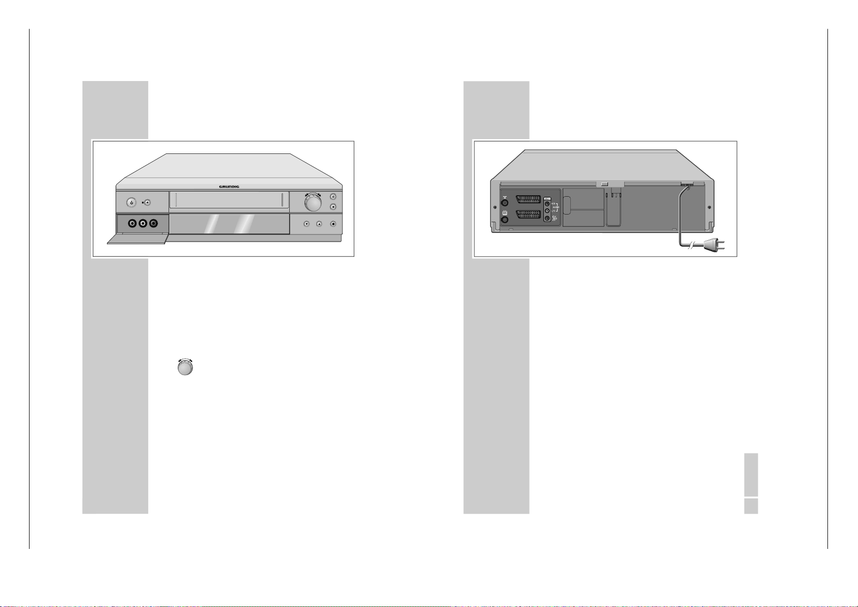
1 - 20 GRUNDIG Service
OVERVIEW
_____________________________________________________________
6
The front of the video recorder
A Switches the video recorder in and out of stand-
by mode (in stand-by mode the time is displayed; in power-saving mode there is no display).
■
N Terminates all drive functions;
ejects the cassette.
VIDEO IN Camcorder video input (socket located behind
the cover panel).
L AUDIO IN R Left and right camcorder audio inputs (sockets
located behind the cover panel).
Turn knob to the left
– during playback:
reverse search;
when stopped: fast rewind.
Turn knob to the right
– during playback:
forward search;
when stopped: fast forward.
II Pause during recording, freeze-frame during
playback.
ı
Starts playback.
*
P
Selects the next channel down.
P
Ü Selects the next channel up.
● Starts recording.
VIDEO IN L AUDIO IN R
P
OVERVIEW
_____________________________________________________________
ENGLISH
7
The back of the video recorder
Ä
Antenna input jack
(for the rooftop antenna).
Ö Antenna output jack
(to the television).
AV2 (DEC./EXT.) Euro-AV (Scart) socket
(to an external device).
AV1 (EURO AV) Euro-AV (Scart) socket
(to the television).
OUT/SORTIE Audio outputs to the HiFi system.
R/D AUDIO L/G
ʐ
SAT control jack for the Grundig
VCR-SAT module and satellite
receiver.
Ü
Mains cable for wall socket.
AV2 (DEC./EXT.)
AV1 (EURO AV)
Operating Hints
This chapter contains excerpts from the user manual. For further particulars
please refer to the appropriate user manual the part number of which is
indicated in the relevant spare parts list.
Allgemeiner Teil / General Section GV 32…, GV 52…, GV 62…
Page 21
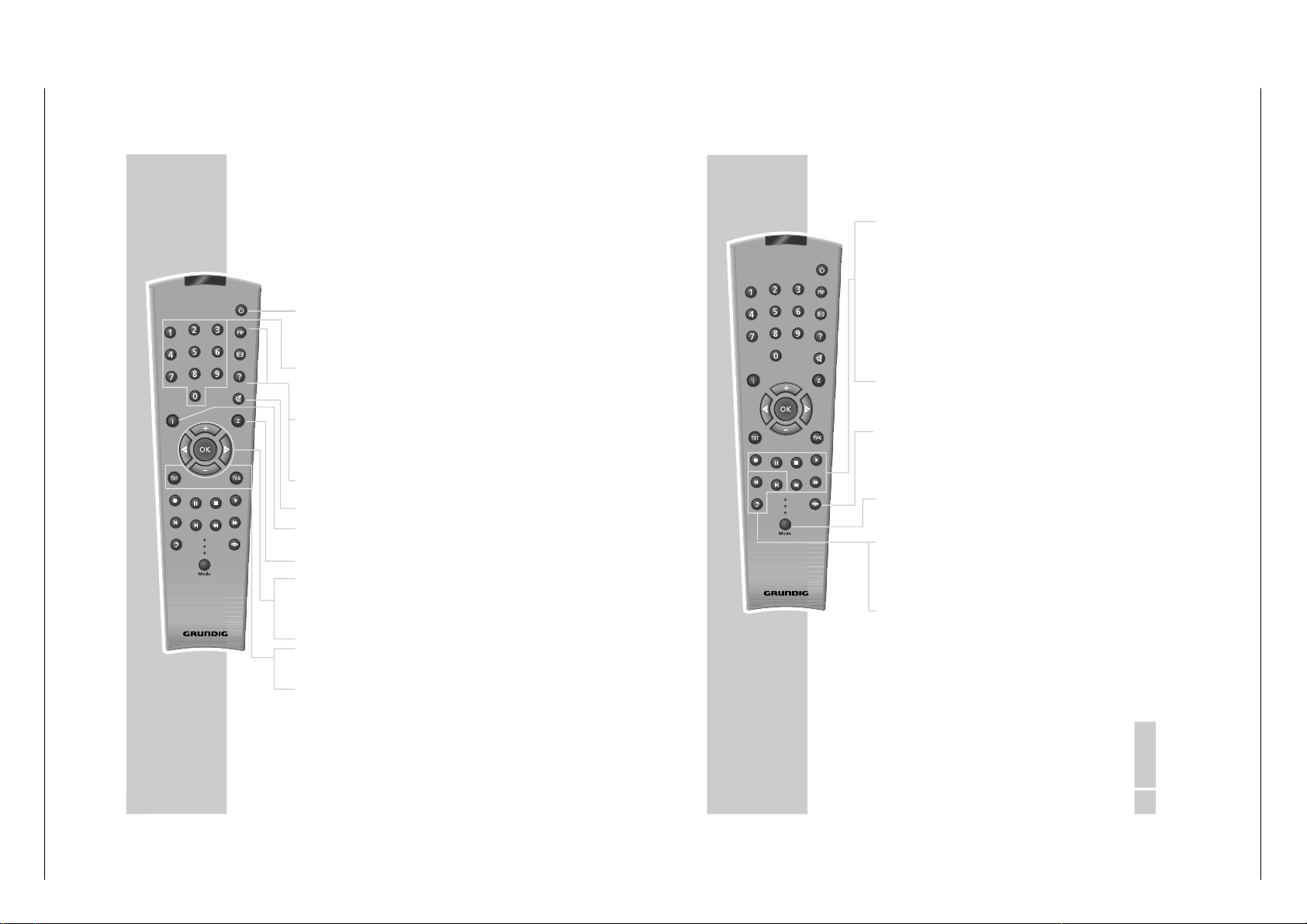
GRUNDIG Service 1 - 21
OVERVIEW
_____________________________________________________________
8
The remote control
The following section describes the most important features of
the remote control. See the relevant chapters in this manual for
information on how to operate the remote control.
Point the remote control at the video recorder.
Ǽ
Pressing once switches the video recorder to
stand-by mode;
pressing again switches off the video recorder
(power-saving mode).
1 ... 0 Switch the video recorder on from stand-by;
numeric keys for various inputs,
» 0 « selects channel positions
»
A I
«, »
A2
« or
»
CV
«.
Digital FX Key has no function.
OSD Activates/deactivates the function and playing
time displays on the television screen.
Clear Deletes data, activates settings, sets the playing
time indicator to
»
0:00:00
«.
d
Switches off the sound on a Grundig television.
i Switches between the main menu and the TV
image.
Timer/SV Activates ShowView recording.
+ – Select channels,
»
+
« up, » – « down;
Select various menu functions.
OK Calls up, confirms and saves data.
® †
Select various functions in the menus.
SP/LP Switches between standard and long play
mode (select playing time before recording).
Timer on Press briefly to activate TIMER-recording; press
and hold down (ca. 3 seconds) to deactivate
TIMER recording.
Tele Pilot 93 V
Digital FX
OSD
Clear
Timer/SV
Timer on
SP/LP
Dub
Index
Audio
Monitor
VCR1
TV
VCR2
OVERVIEW
_____________________________________________________________
ENGLISH
9
● Starts recording.
II Pause during recording, freeze-frame during play-
back.
■
Terminates all drive functions and switches the
video recorder to
”Stop”.
ı
Starts playback.
ľľ
Reverse search during playback;
Fast rewind in
”Stop” mode;
selects the direction of the INDEX search function.
ıı
Forward frame search during playback;
Tape advance in
”Stop” mode;
selects the direction of the INDEX search function
and the zero setting function.
Monitor Switches off the switch voltage of the EURO-AV
socket.
This deactivates the AV channel position on the
television and activates the previously selected
channel position (Monitor mode).
Mode Switches the remote control from video recorder
operation (
» VCR 1«) to TV operation (
» TV«, see
the options described on Page 62) or to the operation of an additional video recorder (
» VCR 2«).
Dub Selects the Dubbing function;
displays the menus on a blue background.
Index Activates the INDEX search functions.
Audio Selects the audio channel for recording and play-
back.
Tele Pilot 93 V
Digital FX
OSD
Clear
Timer/SV
Timer on
SP/LP
Dub
Index
Audio
Monitor
VCR1
TV
VCR2
GV 32…, GV 52…, GV 62… Allgemeiner Teil / General Section
Page 22
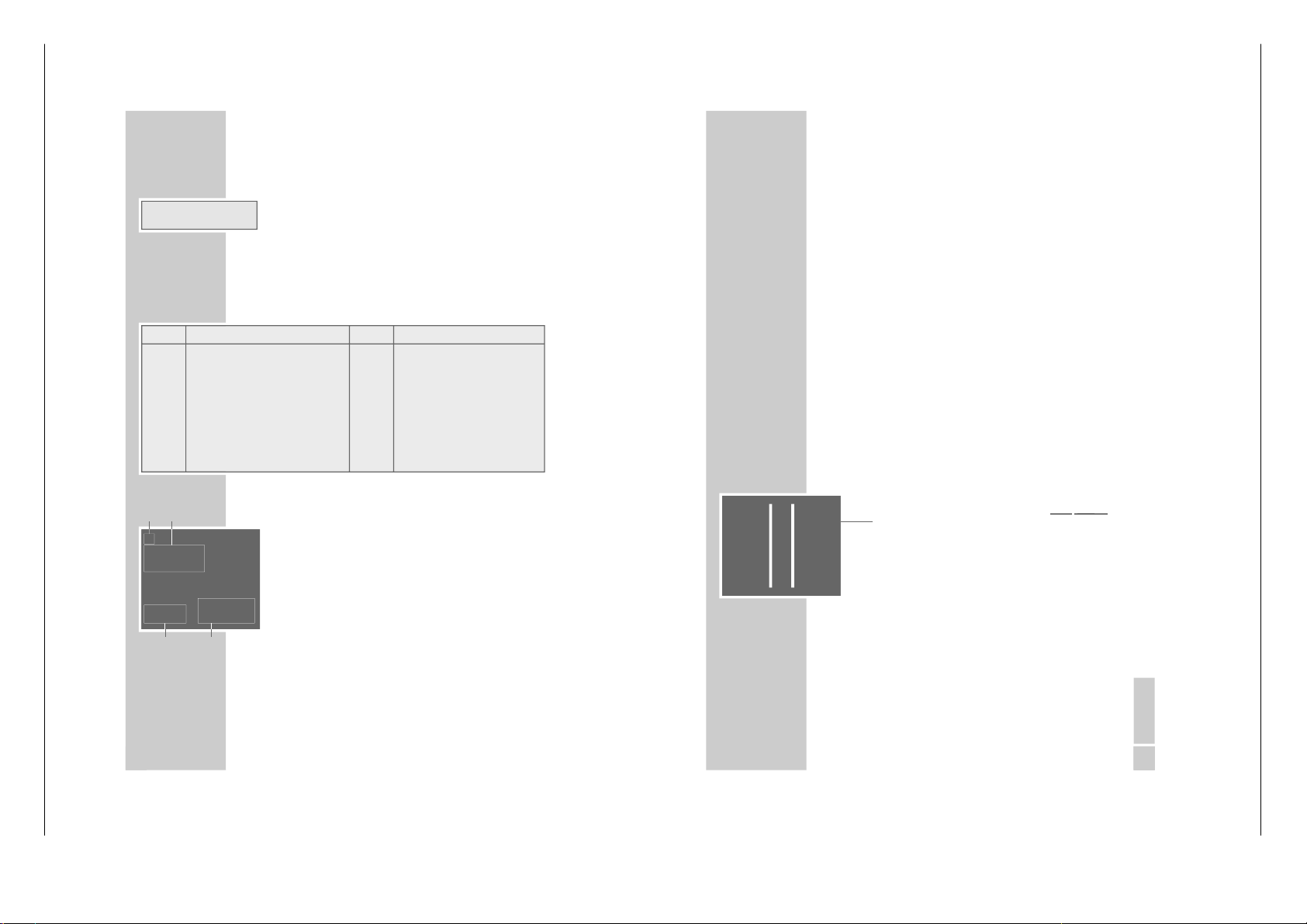
1 - 22 GRUNDIG Service
10
OVERVIEW
_____________________________________________________________
The display on the video recorder
ß
Cassette inserted.
ı
Playback.
VIDEO PIN-8 switch voltage activated.
Ȅ
Illuminates when a TIMER is programmed;
flashes when a TIMER is programmed but not
activated.
˲
Recording.
STEREO Stereo or two-channel sound transmission.
-O
:
OO
:
OO
Shows various functions and conditions:
The OSD display on the television
1
ı
Playback
ıı
Forward frame search or tape advance
ľľ
Backward frame search or tape rewind
II Freeze-frame
II
ı
Slow motion or frame advance
● Record
● II Pause in recording
2
ACC PLUS AUTO Sharpness
END OF TAPE End of tape reached
A.DUB Dubbing function
SP LP Standard or long-playing mode
INTRO-SCAN: Search function
INDEX-SEARCH: Search function
GOTO 0: 00:00 Zero setting
3
12:33 Time
21/06 02 Date
4
USED Elapsed playing time
REM Remaining playing time
2:26.12 Tape display in hours, minutes and
seconds
ı
ACC PLUS AUTO
SP
USED 2:55
12:33 REM 1:05
21/06 02 2:26.12
1
3
4
2
ß
Ȅ
ı
˲
VIDEO STEREO
-8
:
88
:
88
Display Function Display Function
Auto Auto-tracking ; PLAY Playback;
ASr Recording, controlled by the switch- PSE Recording pause;
timer of a satellite receiver; rE Rewind tape;
CASS No tape inserted; rEC Recording;
Cant Continuous playback; SECU Parental lock activated;
dub Audio dubbing; StILL Freeze-frame during playback;
FF Fast forward tape; SLO Slow motion;
FSF Forward frame search; S tOP Stop playback/recording;
FSr Backwards frame search;
ENGLISH
17171717
TUNING
______________________________________________________________
Tuning the video recorder and the
television
You do not need to do this if the video recorder and the television are connected via a EURO-AV (Scart) cable.
1
Switch on the television.
2
Select the
»AV « channel position on the television set for
recorder playback via the antenna cable.
3
Tune the television to a free channel in the UHF band between channel 21 and channel 69. A free channel is one
which does not carry a signal from a television station (you
can only see and hear static).
– Many televisions display the channel number.
4
Store the free channel position on the television.
Note:
When the device is switched on for the first time,
»
Auto
«
flashes in the video recorder display. Keep pressing
»
i«
until »--:--« appears in the display.
5
Press »
Ǽ
« to switch the video recorder to stand-by mode,
and then press and hold down
»
i«.
– The display on the video recorder, for example
»
CH 21
«.
6
Set the channel using
»
* P Ü « on the video
r
ecor
der
.
– The test picture of the video recorder appears on the
television screen.
7
If the quality of the test picture is OK, press
»
OK« to save
the setting.
– The video switches to stand-by.
Note:
If the quality of the test picture is unsatisfactory, or if the picture quality of other channels has deteriorated, then you
should find another free channel on the television and repeat the setting from steps 3 to 7.
You can switch off the station on the video recorder. Fore
more information see the
”Switching the station on the
video recorder on and off
” on Page 52.
Allgemeiner Teil / General Section GV 32…, GV 52…, GV 62…
Page 23

22
PLAYBACK
_________________________________________________________
Preparation
Switch on the television.
Select the channel position
»AV « on the television for the video
recorder.
Insert a recorded video tape into the compartment with the
window facing upwards until it is automatically drawn in.
– The video recorder display contains the following symbol:
»« (= tape symbol).
Note:
If you put a cassette with the protection tab removed into the
video recorder, playback starts automatically.
Basic playback functions
1
Press »
ı
« to start playback.
– Display on the video recorder:
»
PLAY«, information is
displayed briefly on the television screen.
– » Auto« flashes briefly in the video recorder display;
during this time the tracking position of the tape is automatically adjusted.
Note:
If the video recorder is connected to a television with Megalogic functions, the television switches on after playback is
started from operating position stand-by and automatically
switches to program position
»AV «.
2
To switch to freeze-frame/pause press
»
II«.
Press repeatedly to advance the picture frame by frame.
3
Reverse/forwards search, press
»
ľľ
« or »
ıı
« on the
remote control
during playback.
Press several times to change the playback speed;
or
during playback turn the knob on the device to the left or to
the right and hold it.
4
To stop playback, press
»
■ «.
5
To eject the cassette, press
»
■
ə
« on the video
r
ecor
der
.
Note:
Your video recorder automatically switches to powersaving mode when:
– the freeze-frame function is selected for longer than
5 minutes;
– the video recorder is stopped for longer than one minute.
ß
ß
ı
STEREO
St ILL
ß
ı
STEREO
FS r
ß
STEREO
St OP
ß
ı
STEREO
PL AY
ß
ı
STEREO
Au t o
ENGLISH
232323232323232323
PLAYBACK
_____________________________________________________________
Additional playback functions
Calling up information
1
Press the
»
OSD« button to call up information.
– Display on the television screen:
the channel position;
the date and the time;
and shortly thereafter:
»USED« the elapsed playing time on the tape;
»REM« the remaining playing time;
»0:00:00
« the tape counter in hours, minutes and seconds.
– You can call up this information successively on the video
recorder display by pressing
»
OK«.
– The tape counter can be set to
»
0:00:00
« by pressing
»Clear«.
2
Switch off the information display by pressing
»
OSD«.
Fast forward/rewind
1
Press »■« to stop the tape.
2
Press »
ľľ
«, to rewind, fast forward with
»
ıı
« on the
remote control; or
turn the knob on the device to the left or right.
Double playback speed
1
Press »
ı
« during playback.
– The indicator
»
ı
« flashes.
2
Press »
ı
« again to return to normal playback speed.
Slow motion
1
During freeze-frame (playback/pause) press and briefly
hold down
»
II«.
2
Press »
®
« or »
†
« to alter the slow-motion speed.
3
Press »
ı
« to return to normal playback speed.
Frame-by-frame playback
1
During freeze-frame (playback/pause) press
»
II« repea-
tedly.
2
Press »
ı
« to return to normal playback speed.
ß
ı
STEREO
0
:
00
:
56
ß
ı
STEREO
0
:
00
:
00
ß
ı
STEREO
rE
ß
ı
STEREO
PL AY
ß
ı
STEREO
SL O
ß
ı
STEREO
St ILL
GRUNDIG Service 1 - 23
GV 32…, GV 52…, GV 62… Allgemeiner Teil / General Section
Page 24
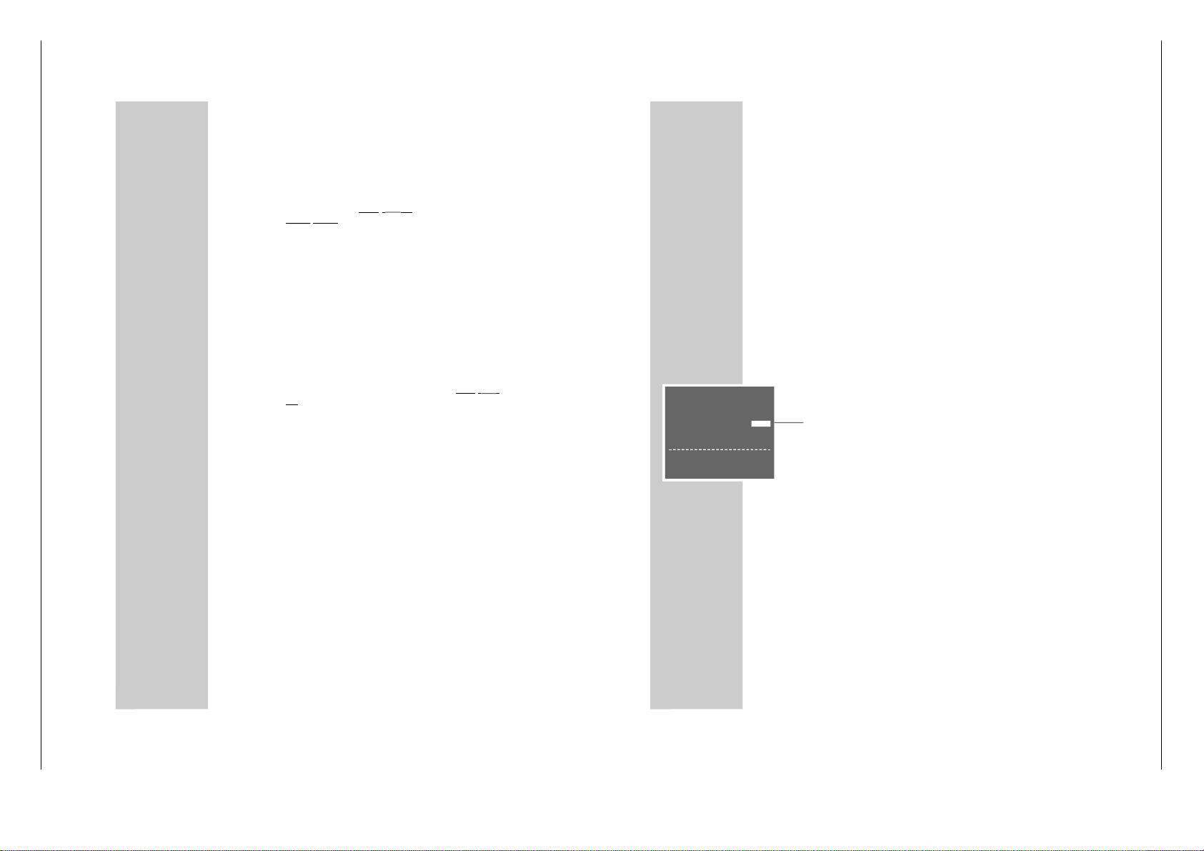
1 - 24 GRUNDIG Service
24
PLAYBACK
_____________________________________________________________
Improving the quality of the freezeframe/
slow motion image
1
In freeze-frame/slow motion mode (playback/pause) press
» *
P
Ü « on the video
r
ecor
der
or »+« or »– « on the
r
emote
contr
ol
to adjust the image according to your taste.
2
Press »
ı
« to return to normal playback.
Note:
The video stops the freeze-frame function after a certain
period of time.
Eliminating picture disturbances
(unwanted lines)
1
During playback, use
»+« and »–« to improve the picture
quality as you see it.
– Your setting is retained until you remove the cassette.
2
If you press
»
*
P
Ü « simultaneously on the video
r
ecor
-
der
it switches to medium tracking.
Setting the picture sharpness (ACC Plus)
The sharpness of the picture can be adjusted to your individual
taste.
1
During playback you can adjust the picture quality by pressing »
®
« (softer) or
»
†
« (sharper).
2
To return to the medium setting, hold down the
»
Clear«
button until you see the menu on the screen.
Playing back NTSC recordings
During playback of NTSC recordings (transmissions following
the American television norm) the video recorder automatically
switches over to this system.
Note:
A perfect freeze-frame is not possible during NTSC playback.
There may be some picture disturbances on NTSC long play
recordings.
26
PLAYBACK
_____________________________________________________________
Continuous playback
This function plays back the contents of the tape up to tape position »
0:00:00
«. At that point, the video recorder automatically
rewinds the cassette to the start and begins playback again.
Activating continuous playback
1
Press »
ı
« to start playback and
»
OSD« to see the tape
counter.
2
At the required position on the tape, press
»
Clear« to
reset the tape counter to
»
0:00:00
«.
3
Press »i« to open the main menu.
– The main menu appears.
4
Select the
» SERVICE
« line using
»
+« or »– « and then
press » OK « to confirm.
– The » SERVICE
« menu appears.
5
Select the
» CONTINUOS-PLAY
« line using
»
+« or »– «.
6
Press »
®
« or »
†
« to activate continuous playback
(display
» ON«) and press
»
OK « to confirm.
– The video recorder automatically rewinds the tape to the
beginning and starts playback there. The buttons on the
device and the remote control (except the
»
i« button) are
disabled during continuous playback.
Deactivating continuous playback
1
Open up the
» SERVICE
« menu by pressing the
»
i« button.
2
Press »
®
« or »
†
« to deactivate continuous playback
(display
» OFF«) and press
»
OK « to confirm.
SERVICE
PIN8-CONTROL OFF
CHILD-LOCK - - - - TAPE-LENGTH E180
■
➔
CONTINUOUS-PLAY OFF
RF-CHANNEL AC21
ATS-RESTART AOFF
EXTENDED MENU - - - -
ɶ ʺ
:SELECT
<>
:CHANGE
OK :ENTER INFO:EXIT
Allgemeiner Teil / General Section GV 32…, GV 52…, GV 62…
Page 25

GRUNDIG Service 1 - 25
ENGLISH
292929292929292929
ENGLISH
29
RECORDING
– IMMEDIATE
_______________________
Recording television programs from the
antenna or the cable connection
Preparation
Switch on the television.
Select the channel position
»AV « on the television for the video
recorder.
Insert a video cassette with sufficient playing time and the tab
intact (i.e. not erase-protected) into the compartment until it is
automatically drawn in.
– The video recorder display contains the following symbol:
»« (tape symbol).
Operation
1
If necessary select long play mode by pressing
»
SP/LP«.
– The video recorder display reads
»
LP
«.
2
Before recording select the television station by pressing
»+« » –« or
»* P Ü « or
»0 ... 9«.
3
To start recording, press
»
●« and briefly hold it down.
Note:
If the video recorder is connected to a television set with
Megalogic functions, the television programme appearing
on the screen can be recorded by pressing
»
●«. It is not
necessary to select the channel position on the video recorder.
4
Press »II« to temporarily interrupt recording.
Note:
During a pause in recording you can switch to another television channel.
5
To finish recording, press
»
■ «.
6
To rewind the tape, press
»
ľľ
«, to fast forward press
»
ıı
« on the remote control;
or
turn the knob on the device to the left or right.
7
To eject the cassette, press
»
■
ə
« on the video
r
ecor
der
.
ß
ß
LP
ß
STEREO
Pr 3
ß
˲
STEREO
rE c
ß
˲
STEREO
PS E
ß
STEREO
St OP
RECORDING
– IMMEDIATE
__________________________________
30
Recording television programs from the
satellite receiver
Preparation
Switch on the television.
Select the channel position
»AV « on the television for the video
recorder.
Insert a video cassette with sufficient playing time and the tab
intact (i.e. not erase-protected) into the compartment until it is
automatically drawn in.
– The video recorder display contains the following symbol:
»« (tape symbol).
Operation
1
Switch on the satellite receiver.
2
Select the required satellite station on the satellite receiver.
3
Select the channel position
»AV « on the video recorder by
pressing
»
0 « and select the channel position by pressing
»–«.
– Display:
»
A2
«.
4
Start recording by pressing and holding down
»
●«.
5
Press » ■ « to end the recording.
Entering the recording stop time
1
During the recording, press
»
●« to advance the recording
stop time in 30 minute increments;
or
press »+« or »–« to enter the stop time to the nearest minute.
– The stop time is only displayed on the television screen.
– The video recorder shows the TIMER display
»
Ȅ
«, and
shuts off when this time is reached.
ß
ß
A2
ß
Ȅ
˲
STEREO
I6
:
00
ß
Ȅ
˲
STEREO
I6
:
30
ß
Ȅ
˲
STEREO
I7
:
00
GV 32…, GV 52…, GV 62… Allgemeiner Teil / General Section
Page 26

1 - 26 GRUNDIG Service
48
SPECIAL SETTINGS
_______________________________________
Sorting, deleting and renaming
television stations
Note:
If the video recorder is connected to a television with Megalogic functions, the settings on pages 48 to 54 are not possible.
Preparation
Switch on the television.
Select the channel position
»AV « on the television for the video
recorder.
Calling up the main menu
1
Press »i« to call up the main menu.
– The main menu appears.
2
Select the
»INSTALL
« line using
»
+« or »–« and activate by
pressing
»
OK «.
– The »INSTALLATION
« menu appears.
3
Select the
»CHANNEL SORT
« line with
»
+« or »–« and
activate by pressing
»
OK «.
– The »CHANNEL SORT
« menu appears.
Notes:
Select the function you require in the
»CHANNEL SORT
«
menu. For information on using these functions see the following sections, each time starting from Step 1.
The current television programme appears in the bakkground. If this makes it difficult to see the menu, press
» Dub« and the menu will appear on a blue background.
Sorting television channels
1
Highlight the
»MOVE« line by pressing
»
OK«.
– The »MOVE« menu appears.
2
Press the
»
+ –
® †
« buttons to select the station you
want to move and then press
»
OK« to highlight it.
3
Select the station with which you want to replace the highlighted station using the
»
+ –
® †
« buttons and press
» OK « to confirm.
4
Press »i« to conclude the setting.
INSTALLATION
CHANNEL SELECTION
CHANNEL SORT
CLOCK
LANGUAGE
ɶʺ
: SELECT
OK :ENTER INFO:EXIT
CHANNEL SORT
MOVE
CANCEL
NAME
ɶʺ
: SELECT
OK :ENTER INFO:EXIT
ENGLISH
4949494949494949
SPECIAL SETTINGS
________________________________________________
Deleting television stations from the list
1
Select the
»CANCEL
« line using
»
+« or »–« and activate
by pressing
»
OK «.
– The »CANCEL
« menu appears.
2
Press the
»
+ –
® †
« buttons to select the station you
want to delete and then press
»
OK« to highlight it.
3
Press »Clear« to delete the station.
4
Press »i« to finish.
Entering names for television stations
1
Select the
» NAME« line using
»
+« or »–« and press
» OK « to confirm.
– The » NAME« menu appears.
2
Select the station you want to enter a name for using
»+ –
® †
« and press
»
OK « to confirm.
3
Press »+« or » –« to enter characters, and
»
®
« or »
†
«
to move to the next position. The name can contain up to
five characters.
4
Press » OK « to save the setting.
5
Press »i« to conclude the setting.
Re-tuning television channels
The ATS search procedure can be redone, which may be helpful if you change your place of residence. Please note that all
saved television stations will be deleted in the process.
1
Press »i« to call up the main menu.
2
Select the
» SERVICE
« line with
»
+« or »– « and activate it
by pressing
»
OK «.
3
Select the
» ATS-RESTART
« line with
»
+« or »– «.
4
Select the
» START« display with
»
®
« or »
†
« and press
» OK « to confirm.
– Further operation is identical to that described in the sec-
tion ”Automatic tuning
”, on page 20, starting at step
2.
CHANNEL SORT
MOVE
CANCEL
NAME
ɶʺ
: SELECT
OK :ENTER INFO:EXIT
CHANNEL SORT
MOVE
CANCEL
NAME
ɶʺ
: SELECT
OK :ENTER INFO:EXIT
SERVICE
PIN8-CONTROL OFF
CHILD-LOCK - - - - TAPE-LENGTH E180
CONTINUOUS-PLAY OFF
RF-CHANNEL AC21
■
➔
ATS-RESTART START
EXTENDED MENU - - - -
ɶ ʺ
:SELECT
<>
:CHANGE
OK :ENTER INFO:EXIT
Allgemeiner Teil / General Section GV 32…, GV 52…, GV 62…
Page 27

GRUNDIG Service 1 - 27
50
SPECIAL SETTINGS
________________________________________________
Skipping television stations
When you are selecting television stations using the
»
+« or
»–« buttons, this function enables you to skip one or more stations.
The channel positions can still be selected with the
»
0 ... 9 «
buttons.
Preparation
Switch on the television.
Select the channel position
»AV « on the television for the video
recorder.
Setting
1
Press »i« to call up the main menu.
2
Select the
»INSTALL
« line using
»
+« or »–« and activate by
pressing
»
OK «.
3
Highlight the
»CHANNEL SELECTION
« line by pressing
» OK «.
4
Highlight the
»CHANNEL PRESET
« line by pressing
» OK «.
– The station tuning menu appears on the screen, and the
»PRESET« line is highlighted.
5
Using »
®
« or »
†
«, or » 0 … 9«, select the station you
want to skip.
6
Select the
»SKIP« line using
»
+« or »–«.
7
Select » ON« by pressing
»
®
«.
8
Press » OK « to save the setting for that station.
9
Press »i« to conclude the setting.
Note:
If you later decide that you do not want to skip the station,
repeat the setting and at Step 7 select »OFF« by pressing
»
†
«.
MENU
TIMER
MODE
INSTALL
SERVICE
ɶʺ
: SELECT
OK :ENTER INFO:EXIT
■
➔
PRESET ARD 01
CHANNEL C06
SOURCE C/S/E
FINE TUNING
‹›
SKIP OFF
COLOR AUTO
DECODER OFF
0-9 :DATA
ɶʺ
:SELECT
<>
:CHANGE
OK :ENTER INFO :EXIT
PRESET ARD 01
CHANNEL C06
SOURCE C/S/E
FINE TUNING
‹›
■
➔
SKIP ON ON
COLOR AUTO
DECODER OFF
ɶʺ
:SELECT
‹›
:CHANGE
OK :ENTER INFO:EXIT
ENGLISH
5151515151515151
SPECIAL SETTINGS
________________________________________________
Setting new television stations from the
antenna or the cable system
Preparation
Switch on the television.
Select the channel position
»AV « on the television for the video
recorder.
Setting
1
Press »i« to call up the main menu.
2
Select the
»INSTALL
« line using
»
+« or »–« and activate by
pressing
»
OK «.
3
Highlight the
»CHANNEL SELECTION
« line by pressing
» OK «.
4
Highlight the
»CHANNEL PRESET
« line by pressing
» OK «.
Note:
If the television picture makes it difficult to see the menu,
press » Dub« and it will appear on a blue background.
5
Press »
®
« or »
†
« or » 0 ... 9 « to select the channel
number for the new television station.
6
Select the
» COLOR
« line by pressing
»
+« or »– « and
select the required television system (
» PAL «, »MESECAM
«
or » AUTO«) with »
®
« or »
†
«.
7
Select the
» CHANNEL
« line with
»
+« or »– «.
Switch from normal channels (display:
»C«) to
special/
hyperband channels (display:
»S«) or special
channels
(display:
»E«) and back by pressing
»
Monitor«.
8
Enter the two-digit channel number using the
»
0 ... 9 «
buttons;
or
start an automatic search by pressing
»
®
« or »
†
«.
9
Fine tune the station if necessary by pressing
»
+« or »–« to
select » FINE TUNING
« and then pressing
»
®
« or »
†
«.
10
Select the
»SKIP« line using
»
+« or »–« and then press
»
†
« to select
»OFF«.
■
➔
PRESET ----- 21
CHANNEL C 00
SOURCE C/S/E
FINE TUNING
< >
SKIP OFF
COLOR AUTO
DECODER OFF
0-9 :DATA
ɶʺ
:SELECT
<>
:CHANGE
OK :ENTER INFO :EXIT
PRESET ----- 21
■
➔
CHANNEL C 49
SOURCE C/S/E
FINE TUNING
< >
SKIP OFF
COLOR AUTO
DECODER OFF
MON.
:C/S/E 0-9 :DATA
ɶʺ
:SELECT
<>
:CHANGE
OK :ENTER INFO :EXIT
■
➔
PRESET SKY 20
CHANNEL C 46
SOURCE C/S/E
FINE TUNING
< >
SKIP OFF
COLOR AUTO
DECODER OFF
0-9 :DATA
ɶʺ
:SELECT
<>
:CHANGE
OK :ENTER INFO :EXIT
GV 32…, GV 52…, GV 62… Allgemeiner Teil / General Section
Page 28

1 - 28 GRUNDIG Service
52
SPECIAL SETTINGS
________________________________________________
11
Press » OK « to save the setting for that station.
– The cursor jumps to the
»PRESET« line and the next chan-
nel position is displayed.
Note:
To tune to more stations repeat steps 5 to 11.
12
Press »i« to finish the setting.
Switching the station on the video
recorder on and off
If there are a lot of stations which your video recorder can
receive in the UHF band between channels 21 and 69, it may
lead to picture impairment when using the recorder.
If the station on the video recorder is switched off, the video
recorder and the television must be connected with a EURO-AV
(Scart) cable (see
”Connection and preparation
” on Page 12,
13 or 15).
Switching off the station on the video
recorder
1
Press »i« to call up the main menu.
2
Select the
» SERVICE
« line with
»
+« or »– « and activate it
by pressing
»
OK «.
– The » SERVICE
« menu appears.
3
Select the
» RF-CHANNEL
« line with
»
+« or »– «.
4
Switch off the station on the video recorder with
»
®
« or
»
†
« (display, for example
» OFF«) and confirm with
» OK «.
Switching on the station on the video
recorder
1
Press »i« to call up the main menu.
2
Select the
» SERVICE
« line with
»
+« or »– « and activate it
by pressing
»
OK «.
– The » SERVICE
« menu appears.
3
Select the
» RF-CHANNEL
« line with
»
+« or »– «.
4
Switch on the station on the video recorder with
»
®
« or
»
†
« (display, for example
» C 21«) and confirm with
» OK «.
SERVICE
PIN8-CONTROL OFF
CHILD-LOCK - - - - TAPE-LENGTH E180
CONTINUOUS-PLAY OFF
■
➔
RF-CHANNEL C21
ATS-RESTART AOFF
EXTENDED MENU - - - -
ɶ ʺ
:SELECT
<>
:CHANGE
OK :ENTER INFO:EXIT
■
➔
PRESET SKY 22
CHANNEL C 00
SOURCE C/S/E
FINE TUNING
< >
SKIP OFF
COLOR AUTO
DECODER OFF
0-9 :DATA
ɶʺ
:SELECT
<>
:CHANGE
OK :ENTER INFO :EXIT
SERVICE
PIN8-CONTROL OFF
CHILD-LOCK - - - - TAPE-LENGTH E180
CONTINUOUS-PLAY OFF
■
➔
RF-CHANNEL OFF
ATS-RESTART AOFF
EXTENDED MENU - - - -
ɶ ʺ
:SELECT
<>
:CHANGE
OK :ENTER INFO:EXIT
ENGLISH
5353535353535353
SPECIAL SETTINGS
________________________________________________
Setting new television stations from the
VCR-SAT module
Preparation
Switch on the television.
Select the channel position
»AV « on the television for the video
recorder.
Setting
1
Press »i« to call up the main menu.
2
Select the
»INSTALL
« line using
»
+« or »–« and activate by
pressing
»
OK «.
3
Highlight the
»CHANNEL SELECTION
« line by pressing
» OK «.
4
Highlight the
»CHANNEL PRESET
« line by pressing
» OK «.
Note:
If the television picture makes it difficult to see the menu,
press » Dub« and it will appear on a blue background.
5
Select the desired channel position, where a new satellite
station is to be set, with the
»
®
« or »
†
« buttons.
6
Select the
» SOURCE
« line using
»
+« or »– « and then
press »
®
« or »
†
« to select the
» SAT« display.
7
Select » SAT-MODULE
« by pressing
»
+« or »– « and then
press »
®
« or »
†
« » MENU« to activate it.
– A menu with the data of the selected satellite station
appears on the screen.
The »FREQU.
« line is marked.
– The menu offers the following settings for the satellite sta-
tion.
PROGRAM 15
Number of the selected satellite station.
FREQU. 109640.0 MHZ
Station frequency of the satellite station.
MENU
TIMER
MODE
INSTALL
SERVICE
ɶʺ
: SELECT
OK :ENTER INFO:EXIT
PRESET SAT15 31
CHANNEL SAT01
■
➔
SOURCE SAT
SAT-MODULE MENU
SKIP OFF
ɶʺ
:SELECT
<>
:CHANGE
OK :ENTER INFO :EXIT
PRESET SAT15 31
CHANNEL SAT01
SOURCE SAT
■
➔
SAT-MODULE MENU
SKIP OFF
ɶʺ
:SELECT
<>
:CHANGE
OK :ENTER INFO :EXIT
Allgemeiner Teil / General Section GV 32…, GV 52…, GV 62…
Page 29

GRUNDIG Service 1 - 29
54
SPECIAL SETTINGS
________________________________________________
POL/ANT. HOR A LOW
LNB settings:
Polarisation HOR (horizontal) VER (vertical);
Satellite selection A (for example, ASTRA) or B (for
example, Eutelsat);
LOW = lower frequency band;
HIGH = upper frequency band.
AUDIO 7.02/720 MHZ
Left/right audio frequency.
MODE STEREO
Select the audio type (STEREO, MONO, 50µS, 75µS,
J17).
Set the sound to obtain optimal sound quality.
AUDIO BW 110 KHZ
Band width setting.
Set the sound to obtain optimal sound quality.
DECODER OFF
Decoder for coded satellite stations on/off.
LNB LO1 9,750 GHz
Oscillator frequency of the satellite receiver (LNB).
CONTRAST 2 (32)
Set the picture contrast of the selected satellite station.
Set to obtain optimal picture quality.
8
Enter the frequency directly with
»
0 ... 9« or
change the frequency step-by-step with
»
®
« or »
†
« or
Press » Index« until the
”new” satellite station appears on
the screen.
9
Select the station data you wish to modify with
»
+«
or »–« and enter the new data directly with
»
0 ... 9«
or change with
»
®
« or »
†
«.
Note:
To go back to the previous menu
– without saving the modi-
fications
– press »
i«.
10
Save changes with
»
OK«.
– The video recorder automatically switches back to the
previous menu display and automatically selects its next
channel position.
11
Quit the setting with
»
i«.
PROGRAM 15
■
➔
FREQU.
10964,0 MHZ
POL/ANT. HOR A LOW
AUDIO 7,02/7,20
MHZ
MODE SSTEREO
AUDIO BW 110 KHZ
DECODER OFF
LNB LO 1 9 , 750 GHZ
CONTRAST 2 (32)
ŃĽ
:SELECT
ľı
:CHANGE
OK :ENTER INFO:EXIT
56
SETTING THE DATE AND TIME
_______________
Automatically updating the time
and date
If channel number 1 on the video recorder is tuned to a station
with teletext, the video recorder uses this to automatically
update its internal clock.
The update takes place daily between 3 A.M. and 6 A.M., thus
enabling the video recorder to recognise the switches to and
from daylight saving time.
Setting the time and date manually
1
Switch on the television and select the channel position
»AV « on the television for the video recorder.
2
Press »i« to open the main menu.
3
Select the
»INSTALL
« line with
»
+« or »–« and then press
» OK « to confirm.
4
Select the
»CLOCK« line using
»
+« or »–« and then press
» OK « to confirm.
– The »CLOCK« menu appears with the
»TIME« item high-
lighted.
5
Enter the time as four digits using
»
0 ... 9 «.
6
Enter the date as four digits using
»
0 ... 9 «.
7
Enter the year as two digits using
»
0 ... 9 «.
Note:
– »
*
« in the menu means that the clock is updated automa-
tically. To disable this function highlight
»
*
« using »
†
«
and then press
»
+« or »–« to switch it off (
»
–« appears
in the display).
8
Press » OK « to conclude the setting.
CLOCK
TIME DATE YEAR
12: –– – –/ –– ––
*
0-9 :DATA
<>
:SELECT
ɶʺ
:CHANGE
INFO :EXIT
CLOCK
TIME DATE YEAR
12:00 10/5 02
*
0-9 :DATA
<>
:SELECT
ɶʺ
:CHANGE
OK :ENTER INFO :EXIT
GV 32…, GV 52…, GV 62… Allgemeiner Teil / General Section
Page 30

1 - 30 GRUNDIG Service
ENGLISH
57
SPECIAL FEATURES
_______________________________________
Selecting special features in the
»MODE«
menu
1
Switch on the television and select the channel position
»AV « on the television for the video recorder.
2
Press » 0 ... 9 « to switch on the video recorder.
3
Press »i« to open the main menu.
4
Select the
» MODE« line using
»
+« or »–« and then press
» OK « to confirm.
– The »MODE« menu appears.
5
Select the function you require from the
»MODE« menu. For
further information on these functions see the following sections, each beginning with Step 1.
OSD – O
n S
creen D
isplay
1
Select the
» OSD-MODE
« line using
»
+« or »–«.
2
Select »OFF«, »AUTO« or » ON« by pressing
»
®
« or
»
†
« and then press
»
OK « to confirm.
3
Conclude the setting by pressing
»
i«.
Automatic power off
If the automatic switch-off function is activated the video
recorder automatically switches to power-saving mode after
3 hours.
1
Select the
» AUTO POWER OFF
« line using
»
+« or »–«.
2
Select »3 HR« or »OFF« by pressing
»
®
« or »
†
« and
then press
»
OK « to confirm.
NTSC playback
This setting enables you to select the colour standard for video
playback on the television connected to the
»
AV1 (EURO
AV) « socket. Select the PAL-TV setting for a PAL television set or
NTSC for a Multinorm television set.
1
Select the
» NTSC PB
« line using
»
+« or »–«.
2
Select »PAL-TV« by pressing
»
®
« or » NTSC (= Multi-
norm)« by pressing
»
†
« and then press
»
OK « to con-
firm.
■
➔
OSD-MODE AUTO
VCR NO. 1
16: 9 AUTO
NTSC PB PAL TV
AUTO POWER OFF OFF
AV2 –IN AV2
–IN
COLOR AUTO
ɶʺ
:SELECT
‹›
:CHANGE
OK :ENTER INFO:EXIT
■
➔
OSD-MODE OFF
VCR NO. 1
16: 9 AUTO
NTSC PB PAL TV
AUTO POWER OFF OFF
AV2 –IN AV2–IN
COLOR AUTO
ɶʺ
:SELECT
‹›
:CHANGE
OK :ENTER INFO:EXIT
OSD-MODE OFF
VCR NO. 1
16: 9 AUTO
NTSC PB PAL TV
■
➔
AUTO POWER OFF OFF
AV2 –IN AV2
–IN
COLOR AUTO
ɶʺ
:SELECT
‹›
:CHANGE
OK :ENTER INFO:EXIT
OSD-MODE OFF
VCR NO. 1
16: 9 AUTO
■
➔
NTSC PB PAL TV
AUTO POWER OFF OFF
AV2 –IN AV2–IN
COLOR AUTO
ɶʺ
:SELECT
‹›
:CHANGE
OK :ENTER INFO:EXIT
58
SPECIAL FEATURES
_______________________________________________
Video recorder operation level
You can use your remote control to operate two GRUNDIG
video recorders independently of one another. Ask your dealer
which GRUNDIG video recorders are suitable.
To avoid interference between the two video recorders you
need to set the operation level on the GV 6263.
1
Select the
» VCR NO.
« line using
»
+« or »– «.
2
Select »2« (or »1«) with »
®
« or »
†
« and then press
» OK « to confirm.
3
Conclude the setting by pressing
»
i«.
– The GV 6263 is set to secondary operating level.
To operate the GV 6263 you must now keep pressing
» Mode« until the
» VCR 2« indicator lights up. You
can then
– within 20 seconds
– select the function you
require.
Operation with a format 16:9 television
For this function, the input sockets of the video recorder must be
correctly adapted.
1
Select the
»16 : 9 « line using
»
+« or »– «.
2
Select »AUTO« with »
®
« or »
†
« and confirm with
» OK «.
3
Conclude the setting by pressing
»
i«.
Setting the EURO-AV2 socket on the video
recorder for the satellite receiver
1
Press »i« to call up the main menu.
– The main menu appears.
2
Select the
» MODE« line using
»
+« or »–« and activate by
pressing
»
OK «.
– The »MODE« menu appears.
3
Select the
» AV2 –IN« line using
»
+« or »–«.
4
Select » AV2 –IN« using »
®
« or »
†
« and press
»
OK «
to confirm.
OSD-MODE OFF
VCR NO. 1
■
➔
16:9 AUTO
NTSC PB PAL TV
AUTO POWER OFF OFF
AV2 –IN AV2–IN
COLOR AUTO
ɶʺ
:SELECT
‹›
:CHANGE
OK :ENTER INFO:EXIT
OSD-MODE OFF
■
➔
VCR NO. 1
16: 9 AUTO
NTSC PB PAL TV
AUTO POWER OFF OFF
AV2 –IN AV2
–IN
COLOR AUTO
ɶʺ
:SELECT
‹›
:CHANGE
OK :ENTER INFO:EXIT
OSD-MODE OFF
VCR NO. 1
NTSC PB PAL TV
AUTO POWER OFF OFF
■
➔
AV2 –IN AV2-IN
COLOR AUTO
ɶʺ
:SELECT
‹›
:CHANGE
OK :ENTER INFO:EXIT
Allgemeiner Teil / General Section GV 32…, GV 52…, GV 62…
Page 31

GRUNDIG Service 1 - 31
ENGLISH
59
SPECIAL FEATURES
_______________________________________________
Selecting special features in the
»SERVICE
« menu
1
Switch on the television and select the channel position
»AV « on the television for the video recorder.
2
Press » 0 ... 9 « to switch on the video recorder.
3
Press »i« to open the main menu.
4
Select the
» SERVICE
« line using
»
+« or »– « and then
press » OK « to confirm.
– The » SERVICE
« menu appears.
5
Select the function you require from the
» SERVICE
« menu.
For further information on these functions see the following
sections, each beginning with Step 1.
Activating the remote control of the
GRUNDIG television set for the video
recorder
If your video recorder is enclosed in a cabinet unit and its
remote control therefore cannot be used, the video recorder
can be operated with the remote control from the television set.
This can be done only when the television and video recorder
are connected via the
»
AV1 (EURO AV)« socket.
1
Select the
» PIN 8-CONTROL
« line with
»
+« or »– «.
2
Select » ON« with »
®
« or »
†
« and confirm with
» OK «.
3
Conclude the setting by pressing
»
i«.
Entering the cassette length
After a cassette has been inserted, the video recorder measures
the cassette running time and, after a few seconds, displays the
running time in hours and minutes. Depending on the tape
position, the remaining playing time (display
»
r 0:00«) and
the elapsed playing time (display
»
u 0:00«) are displayed.
Tapes with a length shorter than 240 minutes are correctly
displayed when the cassette length E 180 is set (basic setting).
For all other cassette types (including E180, E240, E260 and
E300), the running time must be manually entered.
1
Select the
» TAPE-LENGTH
« line with
»
+« or »– «.
2
Select the required cassette length by pressing
»
®
« or
»
†
« and then press
»
OK « to confirm.
3
Conclude the setting by pressing
»
i«.
SERVICE
■
➔
PIN8-CONTROL OFF
CHILD-LOCK - - - - TAPE-LENGTH E240
CONTINUOUS-PLAY OFF
RF-CHANNEL AOFF
ATS-RESTART AOFF
EXTENDED MENU - - - -
ɶ ʺ
:SELECT
<>
:CHANGE
OK :ENTER INFO:EXIT
SERVICE
■
➔
PIN8-CONTROL OFF
CHILD-LOCK - - - - TAPE-LENGTH E240
CONTINUOUS-PLAY OFF
RF-CHANNEL AOFF
ATS-RESTART AOFF
EXTENDED MENU - - - -
ɶ ʺ
:SELECT
<>
:CHANGE
OK :ENTER INFO:EXIT
SERVICE
PIN8-CONTROL OFF
CHILD-LOCK - - - - -
■
➔
TAPE-LENGTH E180
CONTINUOUS-PLAY OFF
RF-CHANNEL AOFF
ATS-RESTART AOFF
EXTENDED MENU - - - -
ɶ ʺ
:SELECT
<>
:CHANGE
OK :ENTER INFO:EXIT
60
SPECIAL FEATURES
_______________________________________________
Automatically switching off the satellite
receiver by switching the video recorder
on/off
When you make timer recordings with satellite television stations, the video recorder switches off the video recorder at the
end of the timer recording. You can activate or deactivate this
control.
1
Select the
» EXTENDED MENU
« line with
»
+« or »– «.
2
Select the
» EXTENDED MENU
« by using
»
0 … 9« to
enter the number 8000.
3
Select the
» SAT-STANDBY
« line using
»
+« or »– «.
4
Select »ON« or » OFF« with »
®
« or »
†
« and then
press » OK « to confirm.
5
Press »i« to terminate the setting.
Switching the Megalogic function on/off
You can switch off the Megalogic function. This can be useful
when you often use your video recorder with different television
sets. This prevents the Megalogic function from transferring
the television stations from the television sets onto your video
recorder.
1
Select the
» EXTENDED MENU
« line with
»
+« or »– «.
2
Call up the
» EXTENDED MENU
« by using
»
0 … 9« to
enter the number 8000.
3
Select the
» MEGALOGIC-LOAD
« line with
»
+« or »– «.
4
Select »ON« or » OFF« with »
®
« or »
†
« and then
press » OK « to confirm.
5
Press »i« to terminate the setting.
SERVICE
PIN8-CONTROL ON
CHILD-LOCK - - - - TAPE-LENGTH E240
CONTINUOUS-PLAY OFF
RF-CHANNEL OFF
ATS-RESTART OFF
■
➔
EXTENDED MENU 8000
ɶ ʺ
:SELECT
<>
:CHANGE
OK :ENTER INFO:EXIT
EXTENDED MENU
COMMERCIAL-STOP OFF
MEGALOGIC-LOAD ON
■
➔
SAT-STANDBY ON
ɶ ʺ
:SELECT
<>
:CHANGE
OK :ENTER INFO:EXIT
SERVICE
PIN8-CONTROL ON
CHILD-LOCK - - - - TAPE-LENGTH E240
CONTINUOUS-PLAY OFF
RF-CHANNEL OFF
ATS-RESTART OFF
■
➔
EXTENDED MENU 8000
ɶ ʺ
:SELECT
<>
:CHANGE
OK :ENTER INFO:EXIT
EXTENDED MENU
COMMERCIAL-STOP OFF
■
➔
MEGALOGIC-LOAD 0N
SAT-STANDBY ON
ɶ ʺ
:SELECT
<>
:CHANGE
OK :ENTER INFO:EXIT
GV 32…, GV 52…, GV 62… Allgemeiner Teil / General Section
Page 32

1 - 32 GRUNDIG Service
ENGLISH
61
PARENT
AL LOCK
____________________________________________
The parental lock allows you to bar access to all functions of
the video recorder.
Activating the parental lock
1
Press »i« to call up the main menu.
– The main menu appears.
2
Select the
» SERVICE
« line with
»
+« or »– « and activate it
by pressing
»
OK «.
– The » SERVICE
« menu appears.
3
Select the
» CHILD-LOCK
« line with
»
+« or »– «.
4
Enter the five-digit security code with
»
0 ... 9 « and press
» OK « to confirm.
– The display
»LOCKED
« appears on the television screen,
all functions of the video recorder are locked.
Switching off the parental lock
1
Press »i« to call up the
» SERVICE
« menu.
2
Enter the five-digit security code with buttons
»
0 ... 9 «
and press
»
OK « to confirm.
– The parental lock is deactivated.
Note:
If you have forgotten the code number, press the buttons
»
†
«, »
®
«, » –«, »+ «, » OK « in succession to deacti-
vate the parental lock.
SERVICE
PIN8-CONTROL OFF
■
➔
CHILD-LOCK - - - - -
TAPE-LENGTH E180
CONTINUOUS-PLAY OFF
RF-CHANNEL AOFF
ATS-RESTART AOFF
EXTENDED MENU - - - -
ɶ ʺ
:SELECT
<>
:CHANGE
OK :ENTER INFO:EXIT
SERVICE
PIN8-CONTROL OFF
■
➔
CHILD-LOCK - - - - -
TAPE-LENGTH E180
CONTINUOUS-PLAY OFF
RF-CHANNEL AOFF
ATS-RESTART AOFF
EXTENDED MENU - - - -
ɶ ʺ
:SELECT
<>
:CHANGE
OK :ENTER INFO:EXIT
Allgemeiner Teil / General Section GV 32…, GV 52…, GV 62…
Page 33

GV 32…, GV 52…, GV 62… Abgleichvorschriften
SW716
D
Abgleichvorschriften
Chassisplatte
Messmittel: Testcassette
Servicearbeiten nach Austausch …
… der Bandtrommel: Abgleich Nr. 1
… des IC601: Abgleich Nr. 1, 2
… des IC605: Abgleich Nr. 1, 2
Abgleich Vorbereitung Abgleichvorgang
1. KopfradLagengeber
2. NVRAM-Optionen
– Testcassette wiedergeben.
– Taste SW716 auf der "Bedieneinheit
rechts" drücken. Im Display erscheint
"TEST".
– Taste »SP/LP« auf der Fernbedie-
nung drücken.
– Betriebsart – Durchschleifbetrieb.
– Taste SW716 auf der "Bedieneinheit
rechts" drücken. Im Display erscheint
"TEST".
– Taste »i« auf der Fernbedienung so
lange drücken (min. 5s) bis auf dem
Bildschirm das Menü für die NVRAMOptionen erscheint.
01 02 03 04 05 06 07 08
09 10 11 12 13 14 15 16
17 18 19 20 21 22 23 24
25 26 27 28 29 30 31 32
33 34 35 36 37 38 39 40
41 42 43 44 45 46 47 48
49 50 51 52 53 54 55 56
57 58 59 60 61 62 63 64
65 66 67 68 69 70 71 72
CNG : OK SAVE : MENU
– Dieser Abgleich stellt automatisch den Kopfumschaltimpuls auf 6,5 ±0,5
Zeilen vor den Vertikal-Synchronimpulsen ein.
– Testbetrieb verlassen durch Ausschalten des Gerätes.
– Mit den Curser-Tasten + –
®†
der Fernbedienung Options-Nummern
gemäß der NVRAM-Options-Liste anwählen und mit »OK« aktivieren bzw.
deaktivieren.
Achtung: Nur bei richtiger Options-Nummern-Aktivierung sind alle Gerätefunktionen gewährleistet.
– Zum Speichern der Options-Nummern die Taste »i« der Fernbedienung
drücken.
– Testbetrieb verlassen durch Ausschalten des Gerätes.
NVRAM-Options-Liste
GV 3200 VPS 4, 5, 13, 20, 51
GV 3205 VPS 4, 5, 10, 13, 20, 35, 41, 42, 51
GV 3242 NIC/2 2, 4, 5, 6, 7, 8, 9, 10, 11, 13, 15, 19, 20, 51
GV 3243 HIFI 2, 4, 5, 6, 7, 9, 10, 11, 13, 15, 19, 20, 51
GV 3245 HIFI 2, 4, 5, 6, 7, 8, 9, 10, 11, 13, 15, 19, 20, 35, 41, 42, 51
GV 3247 HIFI 1, 6, 7, 9, 10, 11, 13, 14, 15, 19, 20, 26, 33, 34, 41, 42, 51
GV 5253 HIFI 2, 4, 5, 6, 7, 9, 10, 11, 13, 14, 15, 18, 19, 20, 29, 50
GV 6262 NIC 2, 4, 5, 6, 7, 8, 9, 10, 11, 13, 14, 15, 18, 19, 20, 24, 29, 49
GV 6263 HIFI 2, 4, 5, 6, 7, 9, 10, 11, 13, 14, 15, 18, 19, 20, 24, 29, 49
GV 6265 HIFI 2, 4, 5, 6, 7, 8, 9, 10, 11, 13, 14, 15, 18, 19, 20, 24, 29, 35, 41, 42, 49
SE 1400 SV 2, 4, 5, 11, 13, 18, 20, 52
SE 1405 HIFI/NIC 2, 4, 5, 6, 7, 8, 9, 10, 11, 13, 15, 18, 19, 20, 50
Ansicht von der Bestückungsseite
SW716
Bedieneinheit rechts Bedieneinheit rechts
GV 32… / GV 52… / SE 14… GV 62…
GRUNDIG Service 2 - 1
Ķ
Page 34

Adjustment Procedures GV 32…, GV 52…, GV 62…
SW716
GB
Adjustment Procedures
Chassis Board
Test aids: Test cassette
Service works on replacement of …
… the tape drum: Adjustment No. 1
… IC601: Adjustment No. 1, 2
… IC605: Adjustment No. 1, 2
Adjustment Preparation Adjustment Procedure
1. Tape drum
position indicator
2. NVRAM options
– Play the test cassette.
– Press the SW716 button on the "Key-
board Control Unit right". "TEST"
appears in the display.
– Press the »SP/LP« button on the
remote control.
– Loop-through mode.
– Press the SW716 button on the "Key-
board Control Unit right". "TEST"
appears in the display.
– Press and hold down (min. 5s) the »i«
button on the remote control until the
menu for the NVRAM options appears
on the picture screen.
01 02 03 04 05 06 07 08
09 10 11 12 13 14 15 16
17 18 19 20 21 22 23 24
25 26 27 28 29 30 31 32
33 34 35 36 37 38 39 40
41 42 43 44 45 46 47 48
49 50 51 52 53 54 55 56
57 58 59 60 61 62 63 64
65 66 67 68 69 70 71 72
CNG : OK SAVE : MENU
– This adjustment sets the tape drum switching impulse automatically to 6.5
±0,5 lines before the vertical sync impulses.
– Exit the test mode by switching the unit off.
– Using the + –
®†
cursor buttons on the remote control select the options
numbers according to the NVRAM options list and then use the »OK«
button to activate or deactivate the option.
Attention: only when activating the options numbers correctly, all unit
functions are guaranteed.
– Press the »i« button on the remote control to store the options numbers.
– Exit the test mode by switching the unit off.
NVRAM options list
GV 3200 VPS 4, 5, 13, 20, 51
GV 3205 VPS 4, 5, 10, 13, 20, 35, 41, 42, 51
GV 3242 NIC/2 2, 4, 5, 6, 7, 8, 9, 10, 11, 13, 15, 19, 20, 51
GV 3243 HIFI 2, 4, 5, 6, 7, 9, 10, 11, 13, 15, 19, 20, 51
GV 3245 HIFI 2, 4, 5, 6, 7, 8, 9, 10, 11, 13, 15, 19, 20, 35, 41, 42, 51
GV 3247 HIFI 1, 6, 7, 9, 10, 11, 13, 14, 15, 19, 20, 26, 33, 34, 41, 42, 51
GV 5253 HIFI 2, 4, 5, 6, 7, 9, 10, 11, 13, 14, 15, 18, 19, 20, 29, 50
GV 6262 NIC 2, 4, 5, 6, 7, 8, 9, 10, 11, 13, 14, 15, 18, 19, 20, 24, 29, 49
GV 6263 HIFI 2, 4, 5, 6, 7, 9, 10, 11, 13, 14, 15, 18, 19, 20, 24, 29, 49
GV 6265 HIFI 2, 4, 5, 6, 7, 8, 9, 10, 11, 13, 14, 15, 18, 19, 20, 24, 29, 35, 41, 42, 49
SE 1400 SV 2, 4, 5, 11, 13, 18, 20, 52
SE 1405 HIFI/NIC 2, 4, 5, 6, 7, 8, 9, 10, 11, 13, 15, 18, 19, 20, 50
View of Component Side
SW716
Keybaord Control Unit right Keyboard Control Unit right
GV 32… / GV 52… / SE 14… GV 62…
2 - 2 GRUNDIG Service
ķ
Page 35

GV 32…, GV 52…, GV 62… Platinenabbildungen und Schaltpläne / Layout of PCBs and Circuit Diagrams
CAPSTAN / DRUM / LOADING MOTOR
CN604
VIDEO & HIFI HEADS
CN301
ACE HEAD
POWER SUPPLY (PS)
KEYBOARD CONTROL
UNIT left (KL)
KEYBOARD CONTROL
UNIT right (KR)
KEYBOARD CONTROL UNIT
right GV62… (KR)
FM SOUND (HIFI)
AUDIO/VIDEO (VS)
IN/OUT (IO)
TUNER/MODULATOR (TM)
OSD/VPS/PDC (OS)
SECAM (SE) STEREO/NICAM
DECODER
(A2/NIC)
SYSTEM/DRIVE CONTROL (SC)
FE HEAD
CN3A02
CN3A02
GND
F/ERASE
Reference
Oscillograms ..... 3-26
A2/NIC ................ 3-19
HIFI ..................... 3-20
IO
(1 AV) ..............
3-11
IO
(2 AV Mono) ....
3-12
IO
(2 AV HiFi) ........
3-13
KL ....................... 3-23
KR ....................... 3-23
OS ...................... 3-18
PS ....................... 3-22
SC ......................... 3-7
SE ....................... 3-17
TM ...................... 3-10
VS ....................... 3-15
GV 32…, GV 52…, GV 62… Platinenabbildungen und Schaltpläne / Layout of PCBs and Circuit Diagrams
Platinenabbildungen und Schaltpläne / Layout of PCBs and Circuit Diagrams
Chassisplatte / Chassis Board
Koordinaten / Coordinates
Verdrahtungsplan / Wiring Diagram
GRUNDIG Service 3 - 1 GRUNDIG Service 3 - 2
BD1SD1 J6
BD1SR1 K3
BD1SS1 K2
BD1SS2 J1
BZ6B01 C1
C1P102 C4
C1P103 C4
C1P104 D5
C1P105 D5
C1P106 D5
C1P108 D5
C1P109 C5
C1P120 C4
C1SD03 J5
C1SD04 J5
C1SD11 J3
C1SD12 J3
C1SD13 K3
C1SR12 K4
C1SR14 K3
C1SS01 K6
C1SS02 K5
C1SS03 K1
C1SS12 K3
C1SS13 K3
C1SS31 J2
C1SS32 J2
C1SS33 K1
C1SS34 K1
C1SS35 J1
C1SS36 J1
C1SS39 J3
C315 F5
C316 G4
C317 F5
C318 F5
C319 F5
C320 F5
C321 F5
C322 F5
C324 G4
C325 G4
C326 F4
C327 F4
C328 G4
C329 G4
C330 F5
C331 F4
C332 G4
C333 G4
C334 G4
C335 G4
C336 G3
C337 G4
C338 G4
C339 G4
C340 G4
C341 F5
C342 F5
C343 G4
C344 H4
C345 H4
C346 G4
C347 G4
C348 G4
C349 H5
C350 H5
C351 G5
C352 F4
C353 F4
C354 F4
C355 G4
C356 K0
C357 B2
C370 H4
C371 F4
C372 F4
C380 F3
C382 G4
C383 H4
C384 B4
C385 B4
C386 H4
C3A01 F5
C3A02 F5
C3A08 H5
C3A09 H5
C3A10 H5
C3A11 E5
C3A12 E5
C3A14 E5
C3A15 G5
C3A16 G6
C3A17 G6
C3A18 G6
C3A21 G5
C3A22 F5
C3A23 F5
C3A24 F5
C3A29 G5
C3A30 G5
C3A31 E5
C3A40 G6
C3A41 G5
C3D01 E5
C3D02 E5
C3D03 E5
C3D04 E5
C3S01 B1
C3S02 B1
C3S03 B1
C3S04 C1
C3S05 C1
C3S06 C1
C3S07 C2
C3S08 C2
C3S09 C2
C3S10 B1
C3S11 B2
C3S12 C2
C3S13 B2
C3S14 B2
C3S15 C1
C401 A4
C402 A5
C403 A5
C404 A2
C405 A5
C406 A4
C407 A5
C408 A4
C410 A5
C4N01 B1
C4N02 B1
C4N03 B1
C4N04 B1
C4N05 A2
C4N06 A2
C4N07 A2
C4N08 A2
C4N09 B2
C4N10 A2
C4N11 A2
C4N12 A2
C4N13 A2
C4N14 A2
C4N15 A2
C4N16 A1
C4N17 A2
C4N18 B1
C4N19 A2
C4N21 A1
C4N22 A1
C4N23 A2
C4N24 A3
C4N25 A2
C4N26 A3
C4N30 A2
C501 H5
C502 H5
C503 H5
C504 H5
C505 H5
C506 H5
C507 H5
C508 H5
C510 H4
C511 H4
C513 H4
C517 H4
C518 I4
C519 I4
C520 I4
C521 I4
C522 I4
C523 H5
C524 I5
C525 I5
C526 H5
C527 H5
C529 H6
C530 H5
C535 I5
C536 J6
C537 I5
C538 I5
C539 I6
C540 I6
C541 H4
C542 I4
C601 C4
C602 C4
C603 E3
C604 F3
C605 H2
C606 D0
C607 J1
C608 G0
C609 I2
C618 C4
C620 D4
C622 D4
C623 C4
C624 H2
C625 H2
C626 H2
C627 H2
C633 B3
C634 J3
C635 D4
C636 D4
C637 D3
C638 I2
C639 I2
C640 I2
C641 I2
C642 C4
C644 G2
C645 D4
C646 I1
C650 H2
C651 I2
C652 A1
C655 H2
C679 B1
C680 I1
C681 I2
C690 D4
C691 D4
C692 D4
C693 E0
C695 D4
C697 D4
C698 D5
C6P01 A3
C6P02 B3
C6P04 A2
C6P05 A3
C6P06 B3
C6P07 B3
C6P08 B3
C6P09 B3
C6P10 B3
C6P11 A3
C6P12 A3
C6P13 A3
C6P15 A3
C701 G0
C702 G0
C703 G0
C750 E2
C751 F2
C752 F2
C801 A5
C802 B4
C803 C6
C804 B4
C805 B4
C806 A5
C809 B5
C810 B5
C811 B5
C812 B5
C813 B5
C814 B5
C815 B5
C821 A5
C822 B6
C826 B6
C834 B5
C837 C5
C838 C5
C841 A5
C842 B5
C843 B5
C844 C5
C845 C6
CN1SS1 K6
CN301 H5
CN3A01 C6
CN3A02 I4
CN3A1S D6
CN604 C4
CN701 B0
CN703 A0
CN703S A0
CN708 K0
CON/B C6
D1P101 D4
D1P102 J4
D1P103 D4
D1SD11 K2
D1SD31 J2
D1SR11 K4
D1SS01 K4
D1SS02 K5
D1SS03 K4
D1SS04 K4
D1SS11 J3
D1SS31 J2
D1SS32 K1
D1SS33 K1
D301 H4
D302 I3
D303 K0
D410 D6
D4N01 D2
D4N02 B1
D601 E0
D602 G2
D603 I1
D605 G2
D612 H2
D701 D0
D702 D0
D703 D0
D704 D0
DT701 F0
F1SS0 K6
FC1SS1 K6
FC1SS2 J6
FL3A01 E5
FL3D01 F5
GP301 H6
HS01 K3
HS02 K1
IC1SS1 J3
IC1SS2 I3
IC301 G5
IC3S01 C2
IC4N01 A1
IC501 I5
IC601 H1
IC604 J1
IC605 A1
IC608 H0
IC6P01 A3
IC701 F0
IC750 F2
IC801 B5
J301 G5
J302 G3
J303 C2
J304 G4
J305 C4
J811 C6
J812 B5
J813 C5
J814 C5
J815 C6
JC801 A6
JC802 C6
L1SS02 K5
L1SS31 K1
L1SS32 K1
L301 F5
L302 F4
L303 H3
L370 H4
L3A01 H5
L3A02 F5
L3A03 F5
L3A50 E5
L3D01 E5
L402 A4
L4N01 A1
L4N02 A2
L4N03 A2
L4N04 B1
L501 I3
L502 I6
L602 H2
L603 D4
L6P03 B3
L6P05 A3
L701 E0
L803 C5
L804 C5
L805 B5
L806 B5
L807 C5
L808 B5
L809 C5
L810 C5
L811 B5
L812 B5
L814 A5
LD601 F3
LD601A F3
PT1SS1 J2
PT601 D1
PT602 G2
Q1P101 D5
Q1P102 D5
Q1P103 D5
Q1P104 C4
Q1P105 C4
Q1P106 D4
Q1P107 C5
Q1P108 J4
Q1SR01 K3
Q1SR02 K4
Q302 F5
Q303 K0
Q350 F4
Q351 B4
Q352 F4
Q3A01 G6
Q3A02 E6
Q3A03 F5
Q3A04 E5
Q3A05 E5
Q3A06 E5
Q3D01 E5
Q3D02 E5
Q3D07 F4
Q601 D1
Q603 D5
Q604 H0
Q605 H0
Q606 H0
Q6P01 B3
Q6P02 B4
Q801 C3
Q802 E2
Q803 E2
Q804 C4
Q806 B5
Q809 C4
Q810 A4
R1P101 I2
R1P102 C5
R1P103 I4
R1P104 D5
R1P105 D5
R1P106 D3
R1P107 C4
R1P108 C4
R1P109 C3
R1P110 C5
R1P115 D4
R1SD11 K4
R1SD12 K3
R1SD13 K4
R1SD14 J4
R1SD15 J4
R1SD16 J3
R1SD31 J2
R1SD32 J2
R1SR11 K4
R1SR12 K4
R1SR14 K3
R1SS03 K1
R1SS10 K4
R1SS11 K3
R1SS32 I3
R1SS33 I3
R1SS34 I3
R303 K0
R315 F5
R316 F5
R320 E2
R321 G3
R322 E2
R323 G4
R324 F5
R325 H4
R326 H4
R327 H4
R328 H4
R329 H4
R330 G4
R331 H4
R332 G3
R333 H5
R334 H5
R335 B3
R336 K0
R350 F4
R352 F4
R360 F4
R370 F4
R371 B4
R372 H5
R373 H5
R374 G3
R375 F3
R3A01 G3
R3A04 G5
R3A05 G5
R3A06 G5
R3A07 G5
R3A08 G5
R3A09 G6
R3A11 E5
R3A12 E5
R3A13 E5
R3A14 E4
R3A16 E5
R3A17 E5
R3A18 E5
R3A23 F5
R3A24 E5
R3A25 F6
R3A26 F5
R3A27 F5
R3A28 F5
R3A29 E4
R3A31 D4
R3A32 F5
R3A33 E4
R3A50 G6
R3A51 E5
R3A60 F5
R3D01 E5
R3D02 E5
R3D03 E5
R3D04 E4
R3S01 B1
R3S02 C1
R401 A5
R402 A5
R403 A5
R404 A5
R406 A5
R407 A6
R408 A5
R4N01 A1
R4N02 A1
R4N03 A1
R4N04 B1
R4N05 A2
R4N06 A2
R501 J6
R502 I4
R503 H4
R505 H6
R506 I4
R507 I5
R508 I5
R509 I5
R510 I6
R511 H6
R512 H6
R514 I6
R516 C5
R517 H6
R518 H6
R519 H5
R520 H6
R521 H5
R522 I5
R533 I5
R540 H5
R545 H5
R546 I6
R547 I5
R550 I5
R551 I5
R552 I5
R553 I5
R570 H4
R571 H4
R573 H4
R601 H2
R602 H2
R603 H2
R604 D0
R605 I3
R606 H0
R607 I1
R608 D3
R609 C3
R610 I1
R611 H0
R612 E0
R613 H2
R614 G1
R630 D1
R631 D2
R632 F0
R637 G0
R638 I1
R639 I1
R640 E1
R641 D3
R642 D3
R644 H2
R651 I1
R656 G0
R657 H0
R660 D3
R661 D4
R666 A1
R667 A1
R668 B1
R669 B1
R670 D2
R671 D2
R672 D2
R674 H0
R675 F2
R676 D2
R678 E1
R679 D1
R680 G2
R682 G2
R685 D4
R690 D4
R691 G2
R692 J1
R693 D4
R694 D4
R695 C2
R696 C3
R697 C2
R698 D4
R6B01 G0
R6P01 A2
R6P02 A3
R6P03 B3
R6P04 B3
R6P05 A3
R6P06 B3
R6P07 B2
R6P08 B3
R6P09 B4
R6P10 B3
R727 D0
R728 D0
R729 D0
R730 D0
R731 D0
R732 F0
R733 E0
R734 E0
R735 E0
R736 E0
R737 E0
R738 F0
R739 F0
R740 F0
R741 F0
R750 F2
R751 F1
R752 F1
R754 F2
R777 I1
R801 C4
R802 C4
R803 C4
R804 C6
R805 C6
R806 C6
R807 A6
R808 B5
R809 A5
R810 B5
R811 B5
R812 A6
R813 C5
R814 C5
R815 C6
R816 C6
R819 B5
R820 B5
R821 B5
R822 B5
R823 D1
R824 D1
R828 A5
R831 B5
R832 B4
R833 A5
R835 B5
R836 B5
R837 B5
R839 A5
R842 A4
R843 B4
R844 C5
R851 B5
R852 B5
R853 A5
R855 B5
R856 B5
R857 B4
RM701 G0
RS601 H0
S601 J3
S601A J3
S602 B3
S602A B3
SC01 K3
SC02 K1
SW601 C2
TM401 A6
TP301 J5
TP302 J5
TP303 J5
TP601 J4
TP602 J5
VA1SS1 K5
W000 D5
W001 B2
W002 C3
W003 C4
W004 C5
W005 I1
W006 I1
W007 I1
W008 I1
W009 I1
W010 I1
W012 H0
W013 J1
W014 H0
W015 H0
W016 C5
W017 G0
W018 G0
W019 G0
W020 G0
W021 G0
W022 E2
W023 H0
W024 H1
W025 H1
W026 H1
W027 G1
W028 J0
W029 C2
W030 G1
W031 G0
W032 I1
W033 G1
W034 G1
W035 E0
W036 I2
W037 H2
W038 G2
W039 D0
W040 H3
W041 E1
W042 A0
W043 E5
W044 C2
W045 A0
W046 G0
W047 D0
W048 A0
W049 A2
W050 A2
W051 G0
W052 A3
W053 H0
W054 J2
W055 G0
W056 B3
W057 G3
W058 E2
W059 B2
W060 B2
W061 D0
W062 G0
W063 B1
W064 G0
W065 D0
W066 G0
W067 F0
W068 G1
W069 C2
W070 H0
W071 C3
W072 E3
W073 D3
W075 B2
W077 C3
W078 C3
W080 C3
W081 D4
W082 C3
W083 E4
W084 A4
W085 D4
W086 C3
W087 C3
W089 B4
W090 A5
W091 D3
W092 B4
W093 C2
W094 H3
W095 C2
W096 F0
W097 F0
W098 E1
W099 E1
W100 E1
W102 D3
W103 E0
W104 F4
W105 G2
W106 D2
W107 E2
W108 E2
W109 E2
W110 I4
W111 D3
W112 D3
W113 D5
W114 D3
W115 D3
W116 D5
W118 E3
W119 E3
W120 B2
W121 C2
W122 E3
W123 F3
W124 E0
W125 G2
W126 H3
W127 G2
W128 E2
W129 G2
W130 G2
W131 B1
W132 G2
W133 G2
W134 C1
W135 F3
W136 G3
W137 F3
W138 G3
W139 G3
W141 F3
W142 F3
W143 H3
W144 B2
W145 H3
W146 H2
W147 H3
W149 H3
W151 G2
W152 H2
W154 J2
W155 H2
W157 I2
W158 I2
W161 I2
W163 D0
W164 H4
W166 H4
W167 H3
W17 J2
W170 D0
W171 E4
W172 C6
W173 D0
W174 E4
W175 F4
W176 F4
W177 E4
W178 E3
W179 E6
W18 J3
W180 A4
W182 E4
W183 E4
W185 E4
W186 D0
W187 D5
W188 D4
W189 H3
W190 C4
W192 A5
W194 C5
W195 C5
W196 C5
W198 A3
W199 B5
W200 F4
W201 K0
W202 K1
W203 C6
W204 C5
W205 C5
W206 B4
W208 H6
W209 B4
W210 D1
W211 D1
W212 B3
W213 D0
W214 A6
W215 D1
W216 A4
W217 B5
W218 A4
W220 B4
W226 C5
W23 J4
W238 B2
W239 B2
W241 E2
W248 D2
W249 D2
W250 B3
W251 D2
W252 D2
W253 D3
W254 D4
W255 B2
W256 C2
W258 B2
W259 B2
W271 D4
W300 B4
W301 B4
W302 F3
W303 B4
W305 A4
W306 A4
W307 E5
W308 A3
W309 A3
W310 A3
W311 A4
W312 A4
W313 B4
W314 A4
W315 A3
W316 A4
W317 A5
W318 B4
W319 C4
W320 C4
W321 B5
W322 F3
W324 D6
W325 E5
W326 E5
W328 J2
W329 H3
W330 G3
W332 G3
W333 H6
W334 C4
W335 D4
W336 D4
W337 D4
W338 E2
W339 D4
W340 E4
W342 H4
W343 I4
W344 A3
W345 C5
W346 H4
W347 I6
W350 J4
W351 B2
W352 I5
W353 H3
W354 D1
W355 B2
W356 F2
W357 F2
W358 E4
W361 F5
W362 E5
W363 C5
W364 E2
W365 F2
W366 F2
W367 C4
W368 B5
W369 A4
W370 E4
W371 A5
W372 I4
W373 I5
W374 H3
W375 E5
W377 A6
W378 H5
W381 C2
W382 I4
W3F01 E4
W403 G5
W405 I3
W406 E5
W407 G4
W408 H4
W409 F3
W410 F3
W411 F3
W412 E3
W413 G4
W414 G4
W415 H5
W416 H5
W419 G5
W420 D5
W422 G5
W425 G3
W426 C5
W427 C5
W428 C5
W429 C5
W430 I6
W431 I6
W432 J5
W433 J5
W437 H4
W438 A3
W439 A5
W440 H6
W441 H6
W442 C2
W443 F3
W444 C4
W445 D1
W450 G2
W501 B2
W502 A4
W503 C3
W504 C2
W507 E4
W510 I3
W513 H4
W514 B4
W515 A4
W520 C2
W521 C2
W522 B2
W555 K0
W556 F5
W558 I3
W660 I3
W701 F0
W702 F0
W704 G1
W705 G2
W706 G3
W752 H2
W759 H5
W760 B4
XT301 F5
XT302 F5
XT4N01 A1
XT601 H2
XT602 H2
XT750 F2
ZD1P01 J4
ZD1P02 D5
ZD1P03 D4
ZD1P04 C5
ZD1SS1 I2
ZD303 K0
ZD401 A4
ZD801 E2
ZD802 A5
ZD803 A5
ZD804 A5
ZD805 B5
ZD806 B4
ZD807 C4
ZD808 A5
ZD809 A5
ZD810 F5
ZD811 F5
ZD812 G6
ZD813 G6
ZD814 C5
ZD815 B6
ZD816 B6
Page 36

Platinenabbildungen und Schaltpläne / Layout of PCBs and Circuit Diagrams GV 32…, GV 52…, GV 62… Platinenabbildungen und Schaltpläne / Layout of PCBs and Circuit Diagrams GV 32…, GV 52…, GV 62…
Chassisplatte / Chassis Board
Ansicht von der Bestückungsseite / View of Component Side
3 - 3 GRUNDIG Service 3 - 4 GRUNDIG Service
Page 37

GV 32…, GV 52…, GV 62… Platinenabbildungen und Schaltpläne / Layout of PCBs and Circuit Diagrams
Chassisplatte / Chassis Board
Ansicht von der Lötseite / View of Solder Side
GV 32…, GV 52…, GV 62… Platinenabbildungen und Schaltpläne / Layout of PCBs and Circuit Diagrams
GRUNDIG Service 3 - 5 GRUNDIG Service 3 - 6
Page 38

Platinenabbildungen und Schaltpläne / Layout of PCBs and Circuit Diagrams GV 32…, GV 52…, GV 62… Platinenabbildungen und Schaltpläne / Layout of PCBs and Circuit Diagrams GV 32…, GV 52…, GV 62…
Chassisplatte – System-/Laufwerksteuerung (SC)
Chassis Board – System/Drive Control (SC)
A
BC DEF GH I J KLMN OPQ RS
BZ601 P10
C601 C2
C602 C2
C605 H6
C606 R10
C607 G7
C609 K3
C618 C3
C620 C3
C622 G5
C623 B4
C624 I5
C625 I6
C626 I6
C627 I6
C633 P4
C634 O4
C635 N2
C636 M2
C637 M2
C638 L3
C639 L3
C640 K3
C641 L3
C642 B4
C644 J3
C645 H3
C646 O5
C650 H5
C651 H5
C652 G4
C679 R11
C680 G6
C681 L2
C691 F4
C692 D3
C693 M10
C695 B3
C697 D3
C698 M2
C701 P8
C702 P8
C703 Q8
C750 G11
C751 G11
C752 H11
CN604 A3
CN701 S11
CN703 S10
CN708 A12
D601 Q11
D602 C6
D603 H6
D605 D6
D612 E6
D702 M7
D703 M7
DT701 P11
IC601 L5
IC604 H6
IC605 G4
IC608 P7
IC701 J10
IC750 D11
L602 J2
L603 C2
L701 L12
LD601 Q4
PT601 P2
PT602 Q2
Q601 H2
Q603 M2
Q604 Q10
Q605 Q10
Q606 Q11
R601 I4
R602 I4
R603 I4
R604 L8
R605 O4
R606 Q10
R607 N5
R608 I5
R609 I5
R610 N5
R611 N7
R612 Q10
R613 J6
R614 I6
R630 F2
R631 H2
R632 L10
R637 P8
R638 N4
R639 N4
R640 H1
R641 L3
R642 L2
R644 L2
R651 H6
R656 P6
R657 P7
R660 F4
R661 B3
R666 H4
R667 H4
R668 I8
R669 I8
R670 O5
R671 O5
R672 P5
R674 P5
R675 Q4
R676 P4
R678 O2
R679 O2
R6801 O10
R682 Q2
R685 B4
R690 G5
R691 Q2
R692 G6
R693 C2
R694 C2
R695 K8
R696 I7
R697 K8
R698 G3
R731 O8
R732 K10
R733 K10
R734 K10
R735 K10
R736 K10
R737 L10
R738 L10
R741 K10
R750 G11
R751 H10
R752 G9
R777 O4
RM701 Q8
RS601 Q5
S601 P4
S602 Q4
SW601 P6
TP601 L2
TP602 R1
W062 M8
W064 M8
W066 M8
XT601 I5
XT602 I6
XT750 G11
1
FROM/TO PS
2
FROM/TO
CAPSTAN/
LOADING/
DRUM MOTOR
3
CN604
4
5
6
7
8
ECO CTL
PC5V
AL 5.8V
LM B+ (PC12V)
C. M B+
PWR CTL
C-FG
CM B+
PC5V
CAP F/R
I-LIMIT
GND (MOTOR)
GND (SIGNAL)
LM B+ (PC 12V)
CM CTL
LM F/R
D-PG/FG
DM CTL
16
Reference
Oscillograms ..... 3-26
A2/NIC ................ 3-19
HIFI ..................... 3-20
(1 AV) .............. 3-11
IO
(2 AV Mono) .... 3-12
IO
(2 AV HiFi) ........ 3-13
IO
KL ....................... 3-23
KR ....................... 3-23
OS ...................... 3-18
PS ....................... 3-22
SC ......................... 3-7
SE ....................... 3-17
TM ...................... 3-10
VS ....................... 3-15
1
19
23
22
21
28
20
6
17
18
5
AUX V. REC
AUX A. L. REC
AUX A. R. REC
’
26
24
25
27
FROM/TO VS
VIDEO ENVE DET
VIDEO H´ D SW
V-LOCK
C-ROTARY SW
H´ D AMP SW
ENV COMP
V-SYNC
C-SYNC
A. MUTE
IIC CLK
IIC DATA
CTL (–)
CTL (+)
F/ERASE H
AV2 V. PB
FROM/TO SE
PB´ H´
SECAM DET H
SECAM H (TRICK H)
TO TM
IIC CLK
IIC DATA
POSITIVE´ L´ (SW1)
L´ CTL (SW2)
AFT
FROM/TO IO
PIN8 CTL
16:9 DET
16:9 CTL
AUX V. REC
AUX A. L. REC
AUX A. R. REC
MEGALOGIC
SAT LINK
RGB CTL
A. SW1
A. SW2
A. SW3
TV REMOCON
FROM/TO HIFI
HIFI H´ D S/W
HIFI ENV
IIC CLK
IIC DATA
A. MUTE
2
3
4
5
6
7
8
TO OS
OSD CLK
OSD DATA
OSD STB
IIC CLK
IIC DATA
CN703
CN701
SYNC DET
TO KR
(GV62…)
CN702
SHUTTLE A/D
AL 5V
S2
GND
S3
K3
K2
K1
S4
K4
TO KR
(GV32…/SE14…)
CN771
K1
K2
K3
K4
S4
S3
S2
S1
9
10
11
12
FROM/TO KL
CN705
GND
AUX A. L REC
AUX A. R REC
GND
AUX V. REC
S1
K2
K1
7 8 9 10
14
11 12 13
CN708
15
A B C D E F G H I J K L M N O P Q R S
3 - 7 GRUNDIG Service 3 - 8 GRUNDIG Service
9
10
11
12
Page 39

GV 32…, GV 52…, GV 62… Platinenabbildungen und Schaltpläne / Layout of PCBs and Circuit Diagrams
Pin PLAY STOP REC Pin PLAY STOP REC
1 0.0V 0.0V 4.8V 51 0.0V 0.0V 0.0V
2 0.0V 0.0V 0.0V 52 0.0V 0.1V 0.1V
3 3.6V 0.0V 3.6V 53 5.2V 0.1V 0.2V
4 3.1V 5.2V 0.0V 54 5.2V 5.2V 5.2V
5 0.0V 5.2V 5.1V 55 5.2V 5.2V 5.2V
6 5.1V 5.2V 5.1V 56 5.2V 5.2V 5.2V
7 5.2V 5.2V 5.1V 57 0.0V 0.0V 0.0V
8 4.2V 4.1V 4.1V 58 5.2V 5.2V 5.2V
9 2.6V 2.6V 2.6V 59 5.1V 5.2V 5.2V
10 2.7V 5.2V 2.7V 60 3.3V 5.2V 5.2V
11 5.2V 5.2V 5.2V 61 5.2V 5.2V 5.2V
12 2.1V 0.3V 2.3V 62 1.2V 2.5V 1.5V
13 2.3V 2.1V 2.2V 63 0.0V 0.0V 0.0V
14 5.2V 5.2V 5.2V 64 5.2V 0.0V 5.2V
15 2.1V 2.2V 2.1V 65 0.0V 0.0V 0.0V
16 2.5V 2.5V 2.4V 66 4.7V 4.8V 4.7V
17 0.0V 0.0V 0.0V 67 5.2V 0.0V 0.0V
18 2.4V 2.4V 2.4V 68 0.0V 0.0V 0.0V
19 2.2V 2.2V 2.8V 69 5.2V 0.0V 5.2V
20 5.2V 5.2V 5.2V 70 5.2V 1.4V 5.2V
21 0.0V 0.0V 0.0V 71 0.0V 0.0V 0.0V
22 0.0V 0.0V 0.0V 72 0.0V 0.0V 0.0V
23 2.3V 2.7V 0.0V 73 0.0V 0.0V 0.0V
24 2.7V 2.3V 2.8V 74 0.0V 0.0V 0.0V
25 0.0V 0.0V 0.0V 75 1.6V 1.2V 1.5V
26 0.0V 0.0V 0.0V 76 5.2V 5.2V 5.2V
27 4.6V 4.6V 4.6V 77 5.1V 5.2V 5.1V
28 4.6V 4.6V 4.5V 78 0.0V 0.0V 0.0V
29 2.4V 2.8V 2.8V 79 0.0V 0.4V 0.4V
30 0.0V 5.2V 0.0V 80 3.7V 3.7V 3.7V
31 0.0V 0.0V 0.0V 81 0.1V 0.2V 0.2V
32 4.7V 4.7V 4.7V 82 2.3V 0.6V 0.0V
33 5.1V 0.0V 0.0V 83 1.3V 0.0V 0.0V
34 1.2V 1.4V 0.7V 84 1.4V 1.8V 0.0V
35 0.0V 0.0V 0.0V 85 2.6V 2.6V 2.8V
36 5.2V 5.2V 5.2V 86 2.6V 2.6V 2.2V
37 1.4V 1.3V 0.7V 87 2.6V 2.6V 2.6V
38 0.0V 0.0V 5.1V 88 2.6V 2.6V 2.6V
39 0.0V 0.0V 0.0V 89 2.6V 2.6V 0.0V
40 0.0V 0.0V 0.0V 90 2.6V 2.6V 2.6V
41 5.2V 5.2V 5.2V 91 0.0V 0.0V 0.0V
42 5.2V 5.1V 5.1V 92 5.2V 5.2V 5.2V
43 0.0V 0.0V 5.1V 93 2.6V 5.1V 2.6V
44 0.0V 0.0V 0.0V 94 1.4V 1.7V 1.4V
45 0.0V 0.0V 0.0V 95 1.3V 1.5V 1.3V
46 5.2V 5.1V 5.1V 96 1.4V 1.7V 1.3V
47 5.2V 5.2V 5.2V 97 1.3V 0.1V 1.3V
48 5.2V 5.2V 5.2V 98 0.1V 0.1V 0.1V
49 5.2V 5.2V 5.2V 99 0.1V 0.1V 0.3V
50 0.1V 0.1V 5.2V 100 0.2V 0.2V 0.2V
IC601
GRUNDIG Service 3 - 9
Page 40

Platinenabbildungen und Schaltpläne / Layout of PCBs and Circuit Diagrams GV 32…, GV 52…, GV 62…
Chassisplatte / Chassis Board – Tuner/Modulator (TM)
A
1
2
B C D E F G
Record
Video
Sound
Playback
Video
Sound
58
AL 5V
PC 5V
AL 33V
FROM PS
AL 5V
PC 5V
AL 33V
1
2
C401 B4
C402 D2
C403 E2
C404 C5
C405 F3
C406 G3
C407 E6
C408 C4
C410 D2
D410 F2
L402 G2
R401 B2
R402 B2
R403 B3
R404 B3
R406 D5
R407 E5
R408 D6
ZD401 F3
57
3
6
5
4
ST1
ST2
ST3
ST4
ST5
TA1
TA2
TA3
TA4
FROM/TO SC
IIC CLK
IIC DATA
POSITIVE´L´ (SW1)
L´CTL (SW2)
AFT
TO A2/NIC
IIC DATA
IIC CLK
SIF REC
TU A. REC
3
4
5
6
Reference
Oscillograms ..... 3-26
A2/NIC ................ 3-19
HIFI ..................... 3-20
(1 AV) .............. 3-11
IO
(2 AV Mono) .... 3-12
IO
(2 AV HiFi) ........ 3-13
IO
KL ....................... 3-23
KR ....................... 3-23
OS ...................... 3-18
PS ....................... 3-22
SC ......................... 3-7
SE ....................... 3-17
TM ...................... 3-10
VS ....................... 3-15
293059
ABC D E F G
VT1
FT4
FT3
FT1
FT2
FROM VS
FSC (4.43M)
TO IO
TU A. REC
TU V. REC
RF A. PB
RF V. PB
5
6
3 - 10 GRUNDIG Service
Page 41

GV 32…, GV 52…, GV 62… Platinenabbildungen und Schaltpläne / Layout of PCBs and Circuit Diagrams
Chassisplatte / Chassis Board – IN/OUT, 1 Euro-AV (IO)
1
2
3
4
5
A
FROM/TO TM
RF A. PB
RF V. PB
TU V. REC
TU A. REC
FROM/TO VS
AV A. REC
TU A. REC
VCR A. PB
TU V. REC
AV1 V. REC
VCR V. PB
BC D E F G
1
2
3
4
5
C806 E4
C822 F6
C837 D3
C845 D1
JC801 F2
L807 E1
L810 D3
L814 G5
Q802 C7
Q804 C7
Q809 E5
R802 D6
R803 D6
R807 F5
R812 E4
R813 F1
R814 F2
R815 E2
R816 E3
R823 D7
R824 B7
R828 E4
R842 E6
TP301 C6
6
FROM SC
7
PIN8 CTL
TV REMOCON
FROM PS
AL 12V
AL 5V
8
AB C D E F G
Record
Video
Sound
Playback
Video
Sound
6
7
8
Reference
Oscillograms ..... 3-26
A2/NIC ................ 3-19
HIFI ..................... 3-20
(1 AV) .............. 3-11
IO
(2 AV Mono) .... 3-12
IO
(2 AV HiFi) ........ 3-13
IO
KL ....................... 3-23
KR ....................... 3-23
OS ...................... 3-18
PS ....................... 3-22
SC ......................... 3-7
SE ....................... 3-17
TM ...................... 3-10
VS ....................... 3-15
GRUNDIG Service 3 - 11
Page 42

3 - 12 GRUNDIG Service
C801 F3
C802 F3
C803 N9
C804 F4
C809 I4
C810 I4
C812 I4
C813 I3
C814 I3
C815 I3
C822 N10
C826 O6
C834 M5
C837 K3
C841 N6
C842 K6
C845 K2
IC801 G4
JC801 O4
JC802 O8
L802 K4
L805 M4
L807 K2
L810 L2
L811 L5
L814 O6
Q802 G9
Q803 I9
Q804 H9
Q806 N5
Q809 K9
Q810 L6
R802 H8
R803 H8
R804 O9
R807 M9
R808 N6
R809 O7
R810 M5
R811 M5
R812 N4
R813 O2
R814 O2
R815 L2
R816 L2
R819 O4
R820 O4
R821 K9
R822 J9
R823 H8
R824 F9
R828 L8
R831 F2
R832 F2
R833 F2
R836 I2
R839 L6
R841 F3
R842 F4
R842 K10
R843 G3
R843 L7
R846 I5
W224 O2
W226 N4
ZD801 I8
ZD805 I9
ZD814 M9
9
10
8
7
6
5
4
3
2
FEGHIK
L
M
NO
FEGHIK
L
M
NO
9
10
8
7
6
5
4
3
2
Record
Luminance
Chrominance
Sound
Playback
Luminance
Chrominance
Sound
RF V. IN
RF A. IN
FROM/TO TM
TU V. OUT
TU A. OUT
AV1 V. REC
AUX A. REC
AV2 V. REC
AV2 V. PB
VCR V. PB
TU A. REC
FROM/TO VS
AV A. REC
TU V. REC
VCR A. PB
A. SW1
RGB CTL
FROM/TO SC
A. SW2
A. SW3
16:9 CTL
16:9 DET
MEGALOGIC
PIN8 CTL
SAT LINK
TV REMOCON
AL 12V
AL 5V
FROM PS
Reference
Oscillograms ..... 3-26
A2/NIC ................ 3-19
HIFI ..................... 3-20
IO
(1 AV) ..............
3-11
IO
(2 AV Mono) ....
3-12
IO
(2 AV HiFi) ........
3-13
KL ....................... 3-23
KR ....................... 3-23
OS ...................... 3-18
PS ....................... 3-22
SC ......................... 3-7
SE ....................... 3-17
TM ...................... 3-10
VS ....................... 3-15
Chassisplatte / Chassis Board – IN/OUT, 2 Euro-AV – Mono (IO)
Platinenabbildungen und Schaltpläne / Layout of PCBs and Circuit Diagrams GV 32…, GV 52…, GV 62…
Page 43

GV 32…, GV 52…, GV 62… Platinenabbildungen und Schaltpläne / Layout of PCBs and Circuit Diagrams
Chassisplatte / Chassis Board – IN/OUT, 2 Euro-AV – HiFi (IO)
EFGHIKLM
1
FROM/TO TM
RF A. PB
RF V. PB
2
TU V. REC
FROM/TO A2/NIC
3
TU A. L REC
TU A. R REC
FROM/TO HIFI
RF A. PB
A. R. PB
4
A. L. PB
AV2. L. REC
AV2. R. REC
AV. A. L. REC
AV. A. R. REC
TU A. L. REC
TU A. R. REC
AUX A. L. REC
AUX A. R. REC
AV2. L. PB
5
AV2. R. PB
Record
Luminance
Chrominance
Sound
Playback
Luminance
Chrominance
Sound
1
2
3
4
5
6
FROM/TO VS
TU V. REC
AV1 V. REC
AUX V. REC
AV2 V. REC
7
AV2 V. OUT
VCR V. PB
8
FROM/TO SC
PIN8 CTL
16:9 DET
16:9 CTL
9
AUX V. REC
AUX A. L. REC
AUX A. R. REC
MEGALOGIC
SAT LINK
RGB CTL
TV REMOCON
FROM PS
10
AL 5V
AL 12V
6
7
8
9
10
EFGHIKLM
C803 L9
C806 I3
C811 K5
C822 L10
C826 M7
C834 K4
C837 H3
C838 H2
C841 K7
C842 H6
C843 I6
C844 H2
C845 H2
JC801 L3
JC802 M9
L803 L9
L804 L10
L805 K4
L806 K4
L807 I1
L808 I1
L809 I2
L810 I2
L811 I5
L812 I5
L814 M7
Q801 I9
Q802 F9
Q803 G9
Q804 G9
Q806 K5
Q809 I10
Q810 K7
R801 I9
R802 G8
R803 G8
R804 L9
R805 L9
R806 L10
R807 K10
R808 K7
R809 L7
R810 K5
R811 K5
R812 K3
R813 M2
R814 M2
R815 I2
R816 I2
R819 M4
R820 M4
R821 I9
R822 H10
R823 G9
R824 F8
R828 I7
R839 K6
R842 I10
R843 K7
R844 I9
W227 K2
ZD801 G9
ZD814 L9
GRUNDIG Service 3 - 13
Page 44

Platinenabbildungen und Schaltpläne / Layout of PCBs and Circuit Diagrams GV 32…, GV 52…, GV 62…
Chassisplatte / Chassis Board – Audio/Video (VS)
Pin PLAY STOP REC Pin PLAY STOP REC Pin PLAY STOP REC Pin PLAY STOP REC
1 5.2V 5.2V 0.7V 26 1.3V 1.5V 1.5V 51 0.0V 0.0V 0.0V 76 0.8V 2.4V 2.4V
2 0.0V 0.0V 0.6V 27 2.1V 2.1V 2.1V 52 1.9V 1.9V 1.9V 77 1.6V 1.5V 1.5V
3 2.3V 2.3V 2.4V 28 4.0V 4.1V 4.0V 53 2.4V 2.4V 2.4V 78 3.4V 2.6V 2.5V
4 0.3V 0.4V 0.8V 29 2.6V 2.6V 2.7V 54 1.9V 1.9V 1.9V 79 1.9V 1.9V 2.5V
5 2.3V 2.3V 2.3V 30 0.4V 0.0V 0.0V 55 5.2V 5.2V 5.2V 80 0.9V 0.9V 4.2V
6 2.3V 2.3V 2.2V 31 1.4V 1.3V 1.2V 56 2.2V 2.3V 2.3V 81 1.1V 1.1V 1.1V
7 2.3V 2.3V 2.2V 32 4.7V 4.7V 4.7V 57 2.2V 2.0V 2.0V 82 0.0V 0.0V 0.0V
8 2.3V 2.3V 2.2V 33 2.9V 3.0V 2.9V 58 2.8V 3.1V 3.1V 83 2.6V 0.7V 0.0V
9 2.2V 2.2V 2.2V 34 0.0V 0.0V 0.0V 59 3.0V 2.9V 2.9V 84 2.7V 0.6V 0.0V
10 2.3V 2.2V 2.3V 35 2.0V 2.0V 2.0V 60 1.6V 1.5V 1.5V 85 0.0V 0.0V 1.0V
11 2.4V 2.3V 2.3V 36 3.0V 3.0V 3.0V 61 1.7V 1.9V 1.9V 86 0.4V 0.4V 0.0V
12 0.0V 0.0V 0.0V 37 1.9V 2.0V 1.9V 62 0.0V 0.0V 0.0V 87 0.7V 1.9V 2.5V
13 2.2V 2.2V 2.2V 38 2.1V 2.1V 2.0V 63 1.2V 1.2V 1.2V 88 0.7V 1.9V 0.7V
14 0.0V 0.0V 0.0V 39 9.5V 9.5V 9.4V 64 0.0V 0.0V 0.0V 89 0.7V 1.9V 0.7V
15 2.3V 2.3V 2.2V 40 0.0V 0.0V 0.0V 65 1.5V 1.8V 1.8V 90 0.7V 1.9V 0.7V
16 0.2V 5.2V 5.1V 41 0.0V 0.0V 0.0V 66 5.2V 5.2V 5.2V 91 5.2V 5.2V 4.1V
17 2.3V 2.3V 2.2V 42 5.1V 5.2V 5.1V 67 0.2V 0.2V 0.2V 92 0.0V 0.0V 0.0V
18 5.2V 5.2V 5.1V 43 2.4V 2.4V 2.4V 68 4.7V 4.7V 4.7V 93 1.9V 1.9V 4.3V
19 4.1V 4.1V 4.0V 44 4.1V 0.0V 0.0V 69 4.5V 4.7V 4.5V 94 1.9V 1.9V 4.3V
20 0.0V 0.0V 0.0V 45 2.5V 2.5V 2.5V 70 2.8V 5.2V 2.8V 95 1.9V 1.9V 4.3V
21 1.9V 3.2V 3.2V 46 2.6V 2.7V 4.6V 71 0.0V 3.3V 3.3V 96 1.9V 1.9V 4.4V
22 2.6V 2.6V 2.6V 47 4.2V 4.2V 4.2V 72 5.0V 5.0V 5.0V 97 0.0V 0.0V 0.0V
23 2.6V 2.6V 2.6V 48 2.9V 3.0V 3.0V 73 1.9V 2.2V 2.2V 98 2.3V 2.3V 2.3V
24 5.0V 5.0V 5.0V 49 3.8V 3.0V 3.0V 74 2.6V 2.5V 2.5V 99 2.3V 2.3V 2.3V
25 3.5V 0.1V 0.1V 50 1.9V 1.9V 1.9V 75 0.7V 2.4V 2.4V 100 2.3V 2.3V 2.4V
IC301
3 - 14 GRUNDIG Service
Page 45

GV 32…, GV 52…, GV 62… Platinenabbildungen und Schaltpläne / Layout of PCBs and Circuit Diagrams
Chassisplatte / Chassis Board – Audio/Video (VS)
GV 32…, GV 52…, GV 62… Platinenabbildungen und Schaltpläne / Layout of PCBs and Circuit Diagrams
2
S
R
Q
Reference
P
Oscillograms ..... 3-26
A2/NIC ................ 3-19
HIFI ..................... 3-20
IO
IO
O
IO
KL ....................... 3-23
KR ....................... 3-23
OS ...................... 3-18
PS ....................... 3-22
SC ......................... 3-7
N
SE ....................... 3-17
TM ...................... 3-10
VS ....................... 3-15
M
L
34 567
Record
(1 AV) .............. 3-11
(2 AV Mono) .... 3-12
(2 AV HiFi) ........ 3-13
Luminance
Chrominance
Sound
Playback
Luminance
Chrominance
Sound
8 9 10 11 12 13 14 15 16 17 18 19 20 21 22 23 24 25 26
FROM/TO SC
VIDEO ENVE DET
ENV COMP
F/ERASE H
CTL (–)
CTL (+)
V-SYNC
C-SYNC
IIC CLK
IIC DATA
V-LOCK
H´ D AMP SW
VIDEO H´ D SW
C-ROTARY SW
A. MUTE
AV2 V. PB
36
35 6 26 33
49 55034
32
FROM/TO OS
VIDEO PB
2FSC
OSD VIDEO PB
31
K
38
J
I
41
FROM/TO SE
FSC (4.43MHz)
C-SYNC
SECAM PB
SECAM REC/PB
SECAM REC
37
H
42
G
F
43
40
FROM/TO HIFI
HIFI CH1
HIFI COMMON
HIFI CH2
MONO A. REC
MONO A. PB
46
47
E
44
D
C
B
A
234 5678 9 10 11 12 13 14 15 16 17 18 19 20 21 22 23 24 25 26
45
48
39
TO TM
FSC (4.43M)
FROM/TO IO
VCR V. PB
AV A. REC
TU A. REC
VCR A. PB
TU V. REC
AV1 V. REC
AUX V. REC
AUX A. REC
AV2 V. REC
AV2 V. PB
BZ601 P10
S
C315 16F
C317 18F
C318 17F
C319 17F
R
C320 19F
C321 19F
C322 19F
C324 21J
C325 22J
Q
C326 21I
C327 21I
C328 21I
C329 21J
C330 21H
P
C331 21H
C332 21M
C333 21M
C334 19N
C335 19N
C336 19N
O
C337 18N
C338 19O
C339 17N
C340 17N
C341 17E
C342 17E
N
C343 13N
C344 13P
C345 12O
C346 11N
C347 11N
C348 9L
C349 10K
M
C350 9J
C351 9J
C352 21K
C353 21K
C354 21L
C355 21L
L
C356 22N
C357 22C
C372 16O
C380 18N
C382 18O
C384 16O
K
C385 15O
C3A01 14F
C3A02 15F
C3A08 15B
C3A09 14B
C3A10 14B
J
C3A11 5C
C3A12 8C
C3A14 6B
C3A15 12E
C3A16 11E
C3A17 12D
I
C3A18 11E
C3A21 11F
C3A22 14F
C3A23 13F
C3A24 15F
C3A29 16F
H
C3A30 16F
C3A31 16F
C3A40 11E
C3A41 13F
C3D01 5F
C3D02 6F
G
C3D03 8F
C3D04 5F
CN301 3J
CN3A01 3D
CN3A02 2F
D301 11P
F
FL3A01 7C
FL3D01 5F
IC301 11G
J301 15F
L301 18E
L302 22J
L370 12P
E
L3A01 14C
L3A02 8C
L3A03 16E
L3A50 6C
L3D01 7F
Q302 20D
D
Q350 17O
Q351 16O
Q3A01 11F
Q3A02 9C
Q3A03 7C
Q3A04 4C
C
Q3A05 4B
Q3A06 5B
Q3D01 6F
Q3D02 7F
Q3D07 8E
R315 17F
B
R316 19F
R320 13N
R321 14N
R322 14N
R323 21I
R324 19E
A
R325 14N
R326 14N
R327 12N
R328 12N
R329 13O
R330 12O
R331 11O
R332 22O
R333 9M
R334 10L
R335 15N
R336 22N
R350 20C
R360 21H
R370 17O
R371 16O
R372 12P
R373 10G
R374 17N
R3A01 13N
R3A04 10G
R3A05 11F
R3A06 12E
R3A07 12E
R3A08 13E
R3A09 13F
R3A11 5D
R3A12 6B
R3A13 7C
R3A14 6B
R3A16 6B
R3A17 5B
R3A18 5C
R3A23 14E
R3A24 9C
R3A25 14D
R3A26 14E
R3A27 15E
R3A28 15E
R3A29 16E
R3A31 14E
R3A32 15D
R3A33 16E
R3A50 9B
R3A51 4C
R3A60 15D
R3D01 6F
R3D02 5F
R3D03 7F
R3D04 7F
W171 4F
W183 4F
W185 4E
W340 4E
XT301 19F
XT302 21G
GRUNDIG Service 3 - 15 GRUNDIG Service 3 - 16
Page 46

Platinenabbildungen und Schaltpläne / Layout of PCBs and Circuit Diagrams GV 32…, GV 52…, GV 62… Platinenabbildungen und Schaltpläne / Layout of PCBs and Circuit Diagrams GV 32…, GV 52…, GV 62…
C6P01 3D
C6P04 2C
C6P05 2C
C6P06 3B
C6P07 2B
C6P08 6C
C6P10 5C
C6P11 5D
C6P12 8D
C6P13 7D
IC6P01 3B
L6P03 5C
L6P05 3C
Q6P01 7B
Q6P02 7C
R6P01 3D
R6P02 6D
R6P03 2B
R6P04 3B
R6P05 5D
R6P06 5B
R6P07 8C
R6P08 8C
R6P09 6C
R6P10 8B
A
B
C
D
E
2
134567
8
9
10
2
134567
8
9
10
A
B
C
D
E
Playback
Video
33
56
55
5
51
54
6
53
52
FROM VS
VIDEO PB
2FSC
OSD VIDEO PB
FROM PS
PC 5V
TO SC
OSD CLK
OSD DATA
OSD STB
IIC CLK
IIC DATA
SYNC DET
OSD VIDEO PB
VIDEO PB
Reference
Oscillograms ..... 3-26
A2/NIC ................ 3-19
HIFI ..................... 3-20
IO
(1 AV) ..............
3-11
IO
(2 AV Mono) ....
3-12
IO
(2 AV HiFi) ........
3-13
KL ....................... 3-23
KR ....................... 3-23
OS ...................... 3-18
PS ....................... 3-22
SC ......................... 3-7
SE ....................... 3-17
TM ...................... 3-10
VS ....................... 3-15
Chassisplatte / Chassis Board – SECAM (SE)
2
I
H
G
F
E
34567
8 9 10
FROM/TO SC
PB´H´
SECAM DET H
SECAM H (TRICK H)
FROM/TO VS
FSC(4.43M)
C-SYNC
SECAM PB
SECAM REC/PB
SECAM REC
I
H
G
F
E
C3S01 3A
C3S02 3B
C3S03 3C
C3S04 4C
C3S05 6C
C3S06 7C
C3S07 7H
C3S08 6G
C3S09 5G
C3S10 4I
C3S11 4I
C3S12 4H
C3S13 4G
C3S14 3G
C3S15 6C
IC3S01 2C
R3S01 3C
R3S02 5C
Chassisplatte / Chassis Board – OSD/VPS/PDC (OS)
D
C
B
A
23 4 5 6 7 8 9 10
FROM PS
PC 5V
Reference
Oscillograms ..... 3-26
A2/NIC ................ 3-19
HIFI ..................... 3-20
(1 AV) .............. 3-11
IO
(2 AV Mono) .... 3-12
IO
(2 AV HiFi) ........ 3-13
IO
KL ....................... 3-23
KR ....................... 3-23
OS ...................... 3-18
PS ....................... 3-22
SC ......................... 3-7
SE ....................... 3-17
TM ...................... 3-10
VS ....................... 3-15
D
C
B
A
3 - 17 GRUNDIG Service 3 - 18 GRUNDIG Service
Page 47

GRUNDIG Service 3 - 19
C4N01 13F
C4N02 14F
C4N03 13F
C4N04 13G
C4N05 11I
C4N06 10I
C4N07 6H
C4N08 6H
C4N09 7H
C4N10 7H
C4N11 7F
C4N12 6F
C4N13 6E
C4N14 6E
C4N15 8C
C4N16 7C
C4N17 8C
C4N18 12F
C4N19 9C
C4N21 10C
C4N22 10C
C4N23 8I
C4N24 8I
C4N25 7E
C4N30 5H
D4N01 5G
D4N02 13H
IC4N01 8D
L4N01 14E
L4N02 5I
L4N03 7C
L4N04 3B
R4N01 11C
R4N02 13D
R4N03 13E
R4N04 13H
R4N05 9I
R4N06 9I
XT4N01 10C
C
D
E
F
G
H
I
J
4
356789
10
11
12 13 14
C
D
E
F
G
H
I
J
4
356789
10
11
12 13 14
6
30
5
60
IIC DATA
FROM TM
TU. L. REC
TU. R. REC
TO IO
(2AV HIFI)
PC 5V
PC 9V
FROM PS
IIC CLK
SIF REC
TU A. REC
Record
Sound
Reference
Oscillograms ..... 3-26
A2/NIC ................ 3-19
HIFI ..................... 3-20
IO
(1 AV) ..............
3-11
IO
(2 AV Mono) ....
3-12
IO
(2 AV HiFi) ........
3-13
KL ....................... 3-23
KR ....................... 3-23
OS ...................... 3-18
PS ....................... 3-22
SC ......................... 3-7
SE ....................... 3-17
TM ...................... 3-10
VS ....................... 3-15
GV 32…, GV 52…, GV 62… Platinenabbildungen und Schaltpläne / Layout of PCBs and Circuit Diagrams
Chassisplatte / Chassis Board – Stereo/NICAM Decoder (A2/NIC)
Page 48

3 - 20 GRUNDIG Service
C501 E6
C502 F6
C503 F6
C504 F6
C505 G6
C506 G6
C507 G6
C508 G6
C510 H5
C511 I4
C513 H5
C517 G3
C518 G3
C519 F3
C520 F3
C521 F3
C522 F3
C523 D6
C524 D6
C525 D6
C526 D7
C527 D7
C529 D6
C530 H6
C535 D4
C536 D4
C537 D4
C538 D5
C539 D5
C540 D5
C541 H4
C542 H4
IC501 D6
L501 T8
R501 F2
R502 E2
R503 I5
R505 F2
R506 E2
R507 B5
R508 B5
R509 B5
R510 B4
R511 E7
R512 D8
R514 B6
R516 B7
R517 E7
R518 E7
R519 E7
R520 F7
R521 E7
R522 B5
R533 B5
R540 E7
R545 G5
R546 C6
R547 C6
R550 B4
R551 B4
R552 C7
R553 C7
R570 H3
R571 H4
8
7
6
5
4
3
2
C
BDEFGH
I
J
8
7
6
5
4
3
2
C
BDEFGH
I
J
65
64
61
24
6
5
62
63
60
HIFI CH2
HIFI COMMON
HIFI CH1
MONO PB
MONO REC
FROM/TO VS
FROM PS
HIFI H`D S/W
HIFI ENV
IIC CLK
IIC DATA
A. MUTE
FROM/TO SC
RF A PB
A. R. PB
A. L. PB
AV2 L. REC
AV2 R. REC
AV1 A. L. REC
AV1 A. R. REC
TU A. L. REC
TU A. R. REC
AV2 A. L. PB
AV2 A. R. PB
AUX A. L. REC
AUX A. R. REC
FROM/TO IO
(2 AV HIFI)
ECO 9V
ECO 5V
Record
Sound
Playback
Sound
Reference
Oscillograms ..... 3-26
A2/NIC ................ 3-19
HIFI ..................... 3-20
IO
(1 AV) ..............
3-11
IO
(2 AV Mono) ....
3-12
IO
(2 AV HiFi) ........
3-13
KL ....................... 3-23
KR ....................... 3-23
OS ...................... 3-18
PS ....................... 3-22
SC ......................... 3-7
SE ....................... 3-17
TM ...................... 3-10
VS ....................... 3-15
Chassisplatte – FM-Ton / Chassis Board – FM Sound (HiFi)
Platinenabbildungen und Schaltpläne / Layout of PCBs and Circuit Diagrams GV 32…, GV 52…, GV 62…
Page 49

GRUNDIG Service 3 - 21
Pin PLAY STOP REC Pin PLAY STOP REC
1 0.0V 0.0V 0.0V 41 2.6V 2.5V 2.5V
2 2.5V 2.5V 2.5V 42 2.5V 2.5V 2.5V
3 9.5V 9.5V 9.5V 43 2.6V 2.5V 2.5V
4 2.5V 2.5V 2.5V 44 2.6V 2.5V 2.5V
5 4.9V 4.9V 4.8V 45 0.2V 0.0V 0.0V
6 2.0V 1.9V 1.9V 46 4.8V 4.9V 0.4V
7 0.0V 0.0V 0.0V 47 2.5V 2.5V 5.0V
8 0.0V 0.0V 0.0V 48 2.6V 2.0V 2.0V
9 0.0V 0.0V 0.0V 49 0.0V 0.0V 0.0V
10 0.0V 0.0V 0.0V 50 0.0V 0.0V 0.0V
11 0.0V 0.0V 0.0V 51 0.0V 0.0V 0.0V
12 4.8V 4.8V 4.8V 52 0.0V 0.0V 0.0V
13 2.6V 2.0V 2.0V 53 0.0V 0.0V 0.0V
14 2.5V 2.5V 2.5V 54 0.0V 0.0V 0.0V
15 4.8V 4.9V 4.8V 55 0.0V 0.0V 0.0V
16 2.5V 2.5V 2.5V 56 0.0V 0.0V 0.0V
17 0.0V 0.3V 0.3V 57 0.0V 0.0V 0.0V
18 1.3V 0.0V 0.0V 58 0.0V 0.0V 0.0V
19 2.6V 2.5V 2.5V 59 0.0V 0.0V 0.0V
20 2.2V 2.5V 2.5V 60 0.0V 0.0V 0.0V
21 2.6V 2.5V 2.5V 61 0.0V 0.0V 0.0V
22 2.6V 2.5V 2.5V 62 0.0V 0.0V 0.0V
23 4.2V 0.0V 0.0V 63 0.0V 0.0V 0.0V
24 1.9V 0.1V 3.9V 64 0.0V 0.0V 0.0V
25 0.0V 0.0V 0.0V 65 2.5V 2.5V 2.5V
26 1.9V 0.1V 3.9V 66 0.0V 0.0V 0.0V
27 1.9V 0.1V 3.9V 67 2.5V 2.5V 2.5V
28 0.0V 0.5V 2.1V 68 2.5V 2.5V 2.5V
29 0.0V 0.0V 0.0V 69 0.0V 0.0V 0.0V
30 2.1V 4.1V 3.9V 70 0.0V 0.0V 0.0V
31 2.3V 4.1V 3.9V 71 0.0V 0.0V 0.0V
32 4.8V 4.4V 4.8V 72 2.5V 2.5V 2.5V
33 2.2V 0.4V 0.0V 73 0.0V 0.0V 0.0V
34 3.5V 2.5V 2.5V 74 5.0V 5.0V 5.0V
35 2.5V 0.0V 0.0V 75 4.3V 4.3V 4.3V
36 2.7V 4.9V 4.8V 76 4.3V 4.3V 4.3V
37 0.0V 0.4V 0.0V 77 0.0V 0.0V 0.0V
38 4.4V 4.6V 4.5V 78 4.4V 4.3V 4.3V
39 4.5V 4.6V 4.5V 79 0.0V 0.0V 0.0V
40 2.8V 0.0V 2.3V 80 4.4V 4.3V 4.3V
IC501
GV 32…, GV 52…, GV 62… Platinenabbildungen und Schaltpläne / Layout of PCBs and Circuit Diagrams
Page 50

3 - 22 GRUNDIG Service
BD1SD1 B5
BD1SR1 C3
BD1SS2 E2
BD1SS3 E3
C1P102 H2
C1P103 H4
C1P104 H5
C1P105 J5
C1P106 J5
C1P108 I3
C1P109 J4
C1P120 I5
C1SD03 B5
C1SD04 B6
C1SD11 B2
C1SD12 C2
C1SD13 C4
C1SR12 C3
C1SR14 C5
C1SS01 B4
C1SS02 B3
C1SS03 F3
C1SS12 C2
C1SS13 C2
C1SS31 F2
C1SS32 F3
C1SS33 F3
C1SS34 F3
C1SS35 F3
C1SS36 F3
C1SS39 F5
CN1SS1 B5
D1P101 H5
D1P102 K6
D1P103 J3
D1SD11 C5
D1SD31 F2
D1SR11 C3
D1SS01 B2
D1SS02 B2
D1SS03 B2
D1SS04 B2
D1SS11 C2
D1SS31 F2
D1SS32 F3
D1SS33 E3
D303 K2
F1SS01 B5
IC1SS1 D5
IC1SS2 D5
L1SS02 B3
L1SS31 F3
L1SS32 F3
PT1SS1 D2
Q1P101 H5
Q1P102 H5
Q1P103 J3
Q1P104 H2
Q1P105 H4
Q1P106 I4
Q1P107 I3
Q1P108 K5
Q1SR01 C3
Q1SR02 C3
Q303 K2
R1P101 I1
R1P102 K3
R1P103 K5
R1P104 I3
R1P105 J3
R1P106 H4
R1P107 H2
R1P108 H3
R1P109 J4
R1P110 I4
R1P115 H5
R1SD11 C2
R1SD12 C4
R1SD13 C2
R1SD14 C3
R1SD15 C3
R1SD16 C2
R1SD31 E5
R1SD32 F5
R1SR11 C5
R1SR12 C4
R1SR14 C5
R1SS03 F3
R1SS10 B2
R1SS11 C2
R1SS32 F5
R1SS33 G5
R1SS34 G5
R303 J2
VA1SS1 B4
ZD1P01 K6
ZD1P02 H5
ZD1P03 J3
ZD1P04 I5
ZD1SS1 F2
ZD303 K2
A
1
2
3
4
5
6
B
C
D
E HIJK
TM
SC (C.M B+)
IO
SC (L.M B+)
IO
HIFI
A2/NIC
SC
sc
VS, TM, IO
SC, VS
VS, SE
SC, TM, OS,
A2/NIC
HIFI
G
F
A
B
C
D
E HIJK
G
F
1
2
3
4
5
6
HIFI
OPTION
1
4
2
3
Reference
Oscillograms ..... 3-26
A2/NIC ................ 3-19
HIFI ..................... 3-20
IO
(1 AV) ..............
3-11
IO
(2 AV Mono) ....
3-12
IO
(2 AV HiFi) ........
3-13
KL ....................... 3-23
KR ....................... 3-23
OS ...................... 3-18
PS ....................... 3-22
SC ......................... 3-7
SE ....................... 3-17
TM ...................... 3-10
VS ....................... 3-15
Chassisplatte – Netzteil / Chassis Board – Power Supply (PS)
Platinenabbildungen und Schaltpläne / Layout of PCBs and Circuit Diagrams GV 32…, GV 52…, GV 62…
Page 51

GV 32…, GV 52…, GV 62… Platinenabbildungen und Schaltpläne / Layout of PCBs and Circuit Diagrams
Bedieneinheit links / Keyboard Control Unit left (KL)
TO SC
Reference
Oscillograms ..... 3-26
A2/NIC ................ 3-19
HIFI ..................... 3-20
(1 AV) .............. 3-11
IO
(2 AV Mono) .... 3-12
IO
(2 AV HiFi) ........ 3-13
IO
KL ....................... 3-23
KR ....................... 3-23
OS ...................... 3-18
PS ....................... 3-22
SC ......................... 3-7
SE ....................... 3-17
TM ...................... 3-10
VS ....................... 3-15
CN708
1
2
Ansicht von der Lötseite / View of Solder Side
CN705
BACD
JC701
BACD
C701 A0
C702 A0
CN705 B0
L704 A0
L705 A0
SW701 A1
SW702 B1
CN708 A1
C701 C1
C702 B1
JC701 D1
L704 C1
L705 C1
SW701 C2
SW702 B2
1
2
Bedieneinheit rechts / Keyboard Control Unit right GV 32…, GV 52…, SE 14… (KR)
BAC
GV 32… SW705 SW707 SW709 SW710 SW711
1
2
TO SC
CN701
3 3
4 4
CN771
SW712 SW713 SW714 SW716
SE 1400 SW704 SW705 SW708 SW710
SW711 SW712 SW714 SW716
SE 1405 SW703 SW704 SW706 SW710
GV 52… SW711 SW713 SW715 SW716
BAC
D
D
E
E
CN701 A1
SW703 C2
SW704 C3
SW705 E1
SW706 D2
SW707 D2
1
SW708 D3
SW709 E1
SW710 E2
SW711 E2
SW712 E3
SW713 D1
SW714 E2
SW715 E2
SW716 E3
2
GRUNDIG Service 3 - 23
Page 52

Platinenabbildungen und Schaltpläne / Layout of PCBs and Circuit Diagrams GV 32…, GV 52…, GV 62…
Bedieneinheit rechts / Keyboard Control Unit right GV 62… (KR)
BAC
TO SC
CN703
1
2
3 3
CN702
BAC
D
D
E
E
1
2
CN703 A1
SW707 C2
SW709 D2
SW710 E2
SW711 C3
SW713 D3
SW716 E3
VR701 D1
Reference
Oscillograms ..... 3-26
A2/NIC ................ 3-19
HIFI ..................... 3-20
(1 AV) .............. 3-11
IO
(2 AV Mono) .... 3-12
IO
(2 AV HiFi) ........ 3-13
IO
KL ....................... 3-23
KR ....................... 3-23
OS ...................... 3-18
PS ....................... 3-22
SC ......................... 3-7
SE ....................... 3-17
TM ...................... 3-10
VS ....................... 3-15
Ansicht von der Lötseite / View of Solder Side
GV 32…, GV 52…, SE 14… GV 62…
CN771 B0
SW703 B2
SW704 B1
SW705 B1
SW706 A1
SW707 A2
SW708 A1
SW709 A1
SW710 B0
SW711 A0
SW712 A0
SW713 A0
SW714 A0
SW715 B1
SW716 A0
SW707 A0
SW709 A0
SW710 B1
SW711 B1
SW713 B0
SW716 B1
VR701 B1
3 - 24 GRUNDIG Service
Page 53

GRUNDIG Service 3 - 25
Reference
Oscillograms ..... 3-26
A2/NIC ................ 3-19
HIFI ..................... 3-20
IO
(1 AV) ..............
3-11
IO
(2 AV Mono) ....
3-12
IO
(2 AV HiFi) ........
3-13
KL ....................... 3-23
KR ....................... 3-23
OS ...................... 3-18
PS ....................... 3-22
SC ......................... 3-7
SE ....................... 3-17
TM ...................... 3-10
VS ....................... 3-15
GV 32…, GV 52…, GV 62… Platinenabbildungen und Schaltpläne / Layout of PCBs and Circuit Diagrams
Blockschaltplan / Block Circuit Diagram
Page 54

Platinenabbildungen und Schaltpläne / Layout of PCBs and Circuit Diagrams GV 32…, GV 52…, GV 62…
Oszillogramme / Oscillograms
1
3
Mode: Playback
Mode: Playback
1
3
Mode: Standby
Mode: Standby
2
4
Mode: Playback
Mode: Playback
2
4
Mode: Standby
Mode: Standby
5
9
#
Mode: Playback
Mode: Playback
Mode: Playback
6
0
$
Mode: Playback
Mode: Playback
Mode: Playback
7
!
%
Mode: Playback
Mode: Playback
Mode: Playback
8
@
^
Mode: Playback
Mode: Playback
Mode: Playback
)
(
&
Mode: Playback
3 - 26 GRUNDIG Service
*
Mode: Playback
Mode: Playback
Mode: Playback
Page 55

GV 32…, GV 52…, GV 62… Platinenabbildungen und Schaltpläne / Layout of PCBs and Circuit Diagrams
¡
Mode: Record
∞
Mode: Picture search forward
™
§
Mode: Record
Mode: Playback
£
Mode: Playback
≥
Mode: Remote Control
≤
•
Mode: Playback
Mode: Playback
ª
Mode: Record
33
Mode: Record / Playback
fl
Mode: Playback
º
Mode: Record
›
Mode: Record
‡
Mode: Record SP
⁄
Mode: Record
fi
Mode: Record
°
Mode: Record LP
¤
fl
·
Mode: Record
Mode: Record
Mode: Record
‚
·
Mode: Playback
GRUNDIG Service 3 - 27
Mode: Playback
=
Mode: Playback
+
Mode: Record
Page 56

Platinenabbildungen und Schaltpläne / Layout of PCBs and Circuit Diagrams GV 32…, GV 52…, GV 62…
<
,
Mode: Record
47
Mode: Playback
?
Mode: Record
Mode: Playback
.
Mode: Record
;
Mode: Playback SP
>
Mode: Record
;
Mode: Playback LP
:
Mode: Picture search forward
54
Mode: Playback
58
Mode: Playback
51
Mode: Playback
55
Mode: Playback
59
Mode: Record
52
Mode: Playback
56
Mode: Playback
60
Mode: Record
53
Mode: Playback
57
Mode: Playback
61
Mode: Record
62
Mode: Record
3 - 28 GRUNDIG Service
63
Mode: Playback
64
Mode: Playback
65
Mode: Playback
Page 57

GV 32…, GV 52…, GV 62… Laufwerk
Laufwerk
Die angegebenen Positionsnummern (z.B. K200) entsprechen den
Positionsnummern in den Explosionszeichnungen und Ersatzteillisten.
1. Messgeräte / Messmittel
Regeltrenntrafo
Zweikanaloszilloskop mit Tastköpfen 10:1
Materialnummer
Nylonhandschuhe ...................................................... handelsüblich
Schraubendreher (eingesägt) ............ handelsüblich
Testcassette (HiFi) .......................... 927540101600
Drehmomentcassette ....................... 759880471200
2. Laufwerkübersicht
Laufwerkoberseite
G530 G420 K240 G001 G450 G480 B560 G555 G520 B410
B474
B452
B468
K490
G546
K530 B478 K250 K110 K330 K188 K182 K340 K140
Fig. 1
B410 Lademotor
B452 Kurvenrad
B468 Andruckrollen-Umlenkhebel
B474 Schubstange
B478 Freigabehebel
B560 Capstanwelle
G001 Bandtrommeleinheit
G420 Fädelschlitten links
G450 Fädelschlitten rechts
G480 A/C-Kombikopf
G520 Band-Rückführungshebel
G530 Hauptlöschkopf
G546 Cassettenklappen-Hebel
G555 Andruckrolle
K110 Wickelteller links
K140 Wickelteller rechts
K182 Schwenkrad
K188 Getriebe
K240 Bandzugfühler
K250 Bremsband
K330 Wickeltellerbremse links
K340 Wickeltellerbremse rechts
K490 Cassetten-Lift
K530 Lift-Hebel
Laufwerkunterseite
B452 B448 B560 G542 B500 B484 B488
B456 B464 K200
K470 B458
Fig. 2
B448 Zahnrad
B452 Kurvenrad
B456 Zahnrad
B458 Zahnrad
B464 Steuerschieber
B484 Fädelantriebsrad
B488 Fädelarm links
B500 Fädelarm rechts
B560 Capstanmotor
G530 Hauptlöschkopf
G542 Antriebsriemen
K200 Riemenscheibe
K470 Lift-Schieber
G530
GRUNDIG Service 4 - 1
Ķ
Page 58

Laufwerk GV 32…, GV 52…, GV 62…
3. Ausbauhinweise
3.1 Lademotor
– Schraube A (Fig. 3) herausdrehen.
– Lademotor (B410, Fig. 3) nach hinten herausnehmen.
B410
A
B448
B452
Fig. 3
K470
3.2 Cassetten-Lift
– Laufwerkstellung für den Ausbau des Cassetten-Liftes ist Eject:
– Lademotor ausbauen (Punkt 3.1).
– weißes Zahnrad (B448, Fig. 3) so lange entgegen dem Uhrzeiger-
sinn drehen bis der Cassetten-Lift in Laufwerkstellung Eject ist.
– gefederten Lift-Hebel B (Fig. 4) spannen, Arretierung C lösen und
Cassetten-Lift (K490, Fig. 1) herausnehmen.
Montagehinweis:
– Cassetten-Lift so einsetzen, dass die beiden linken Führungsstifte
D (Fig. 5) in die Führung des Lift-Hebels (K530) und in die Lift-
Führungen des Rahmens eintauchen.
– gefederten Lift-Hebel B (Fig. 4) spannen, Arretierung C lösen
(spannen) und Cassetten-Lift in die rechte Führung des Lift-Hebels
einsetzen.
Fig. 6
H
Fig. 7
B452 B448
A
3.5 AC-Kombikopf
– gegebenenfalls Steckverbindung lösen.
– Schraube I (Fig. 8) herausdrehen und AC-Kombikopf (G480)
abnehmen.
Der Einbau erfolgt in umgekehrter Reihenfolge.
Montagehinweis
– Nach dem Austausch des Kombikopfes sind alle Einstellungen, wie
in den Punkten 4.2, 4.3 und 4.4 beschrieben, durchzuführen.
I
G480
A
B
K
C
K530
G546
C
D
E
F
B
K490
K530
Fig. 4 Fig. 5
3.3 Lift-Hebel
– Cassetten-Lift ausbauen (Punkt 3.2).
– Rastnase des Lift-Hebels nacheinander durch die Löcher E (Fig. 5)
und F ausrasten und Lift-Hebel (K530) herausnehmen.
3.4 Lift-Antrieb
– Lift-Hebel ausbauen (Punkt 3.3).
– Lift-Schieber (K470, Fig. 3) zum Zahnrad (B452) schieben und
Cassettenklappen-Hebel (G546) abnehmen.
– Lift-Schieber (K470, Fig. 3) zur Vorderseite schieben und abneh-
men.
– schwarzes Kurvenrad (B452, Fig. 3) und weißes Zahnrad (B448)
abnehmen.
Montagehinweis:
– weißes Zahnrad (B448, Fig. 3) einsetzen.
– schwarzes Kurvenrad (B452, Fig. 7) bei ausgefädelter Laufwerk-
stellung so einsetzen, dass die Markierung A zur Achse des weißen
Zahnrades (B448) zeigt.
– Lift-Schieber (K470, Fig. 3) einsetzen, auf das Kurvenrad (B452)
drücken und nach hinten schieben.
– Cassettenklappen-Hebel (G546, Fig. 6) so einsetzen, dass die
Führung des rechten Seitenteils in der Führungsnut H ist.
– Der weitere Einbau erfolgt in umgekehrter Reihenfolge.
Fig. 8
B560
3.6 Capstanmotor
– Antriebsriemen (G542, Fig. 2) abnehmen.
– gegebenenfalls Steckverbindung lösen.
– 3 Schrauben K (Fig. 8) herausdrehen.
– Capstanmotor (B560, Fig. 8) aus dem Laufwerk nehmen. Die Cap-
stanwelle darf dabei gefettete Teile des Laufwerks nicht berühren.
Der Einbau erfolgt in umgekehrter Reihenfolge.
Zu beachten ist dabei, dass die Capstanwelle fettfrei sein muss
(gegebenenfalls reinigen).
3.7 Bandtrommeleinheit
– gegebenenfalls Steckverbindung lösen.
– 3 Schrauben L (Fig. 9) herausdrehen.
– Abschirmblech (Fig. 9) abnehmen.
– Bandtrommeleinheit (G001, Fig. 9) vorsichtig aus dem Laufwerk
nehmen.
Der Einbau erfolgt in umgekehrter Reihenfolge.
Einstellungen und Kontrollen nach dem Austausch
– Bandlauf kontrollieren (Punkt 4.7.3).
– Kopfrad-Lagengeber einstellen (Abgleich Nr. 1, Seite 2-1).
4 - 2 GRUNDIG Service
Ķ
Page 59

GV 32…, GV 52…, GV 62… Laufwerk
B478 K240 K250 K330 K350 K340 B474 B468
L
ABSCHIRMBLECH
GROUND PLATE
P
N
Fig. 9
G001
3.8 Andruckrollen-Einheit
– Rastnase M (Fig. 10) lösen.
– Andruckrollen-Halter (K546, Fig. 10) im Uhrzeigersinn schwenken
und abnehmen.
– Andruckrollen-Einheit (G555, Fig. 10) herausnehmen.
– gegebenenfalls Schubstange (B474, Fig. 10) herausnehmen.
Montagehinweis:
– Schubstange (B474, Fig. 11) am Hebel B468 einhängen.
– Schubstange auf Rechtsanschlag schieben.
– Andruckrollen-Einheit so einsetzen, dass die Markierung B
(Fig. 10) parallel zur Schubstange verläuft.
– Andruckrollen-Halter (K546) wieder anbringen.
K546
M
B
G555
B474
Fig. 10
3.9 Wickelteller-Bremse rechts
– Cassetten-Lift ausbauen (Punkt 3.2).
– Feder (K350, Fig. 11) ausbauen.
– 2 Rastnasen N (Fig. 11) lösen und rechte Wickelteller-Bremse
(K340) herausnehmen.
Der Einbau erfolgt in umgekehrter Reihenfolge.
Montagehinweis:
– Die Feder (K350) ist entsprechend der Fig. 11 einzusetzen.
3.10 Wickelteller-Bremse links
– Cassetten-Lift ausbauen (Punkt 3.2).
– Feder (K350, Fig. 11) ausbauen.
– Rastnase O (Fig. 11) lösen und linke Wickelteller-Bremse (K330)
herausnehmen.
Der Einbau erfolgt in umgekehrter Reihenfolge.
Montagehinweis:
– Die Feder (K350) ist entsprechend der Fig. 11 einzusetzen.
Fig. 11
Fig. 12
O
C
D
K240
3.11 Bremsband / Bandzugfühler
– Wickelteller-Bremse links ausbauen (Punkt 3.10).
– Lademotor ausbauen (Punkt 3.1).
– Lift-Hebel (K530, Fig. 6) bis Anschlag nach innen schieben.
– Zahnrad (B448, Fig.3) im Uhrzeigersinn bis Anschlag drehen.
– Freigabehebel (B478, Fig. 11) durch Drücken lösen und weißes
Zahnrad (B448, Fig. 3) im Uhrzeigersinn so lange weiter drehen, bis
der Bandzugfühler im Bereich des Löschkopfes ist.
– Bremsband (K250, Fig. 11) vom Wickelteller abnehmen, im Uhrzei-
gersinn bis Anschlag drehen und herausnehmen.
Hinweis: Auf den Filz des Bremsbandes darf kein Fett / Öl gelangen.
– Bandzugfühler (K240, Fig. 11) im Bedarfsfall ausbauen:
– Feder des Bandzugfühlers an der Laufwerkunterseite aushängen.
– Verriegelung in Pfeilrichtung C (Fig. 12) nur so weit biegen, dass
der Bandzugfühler herausnehmbar ist (Achtung, Bruchgefahr!).
– Bandzugfühler (K240, Fig. 12) herausnehmen.
Montagehinweis:
– Nach dem Einbau des Bandzugfühlers ist die Verriegelung bis
maximal zur Markierung D (Fig. 12) zu biegen.
Der Einbau erfolgt in umgekehrter Reihenfolge.
3.12 Wickelteller
– Wickelteller-Bremsen und Bremsband ausbauen (Kap.3.9…3.11).
– Wickelteller (K140 / K110, Fig. 1) herausnehmen.
Der Einbau erfolgt in umgekehrter Reihenfolge.
3.13 Steuerschieber
– Antriebsriemen (G542, Fig. 2) abnehmen.
– Rastnase P (Fig. 11) lösen und Fädelantriebsrad (B484, Fig. 2)
herausnehmen.
– Schraube Q (Fig. 13) herausdrehen und Halter entnehmen.
– Zahnrad (B458, Fig. 13) herausnehmen.
– Steuerschieber (B464, Fig. 13) herausnehmen.
Montagehinweis
– Cassettenlift absenken:
– Lademotor ausbauen (Punkt 3.1).
– weißes Zahnrad (B448, Fig. 3) so lange im Uhrzeigersinn drehen
bis das Loch E (Fig. 13) der Achse des Zahnrades (B458)
gegenübersteht.
– Andruckrollen-Umlenkhebel (B468, Fig. 13) zur Laufwerkvorder-
seite schieben.
– Steuerschieber (B464) in die Führungen R (Fig. 13) des Chassis so
einlegen, dass die Markierung F der Achse des Zahnrades (B458)
gegenübersteht. Des Weiteren müssen die Führungsstifte X der
Hebel (B468 / B478) sowie der Bremsen (K340 / K330) in die
Aussparungen des Steuerschiebers eingreifen (Fig. 13).
– Zahnrad (B458, Fig. 13) so einsetzen, dass die Löcher E / G
gegenüber stehen. Des Weiteren muss die Markierung H auf die
Markierung F des Steuerschiebers zeigen.
– Halter mit Schraube Q (Fig. 13) festschrauben.
– Fädelantriebsrad (B484, Fig. 13) bei ausgefädelter Laufwerk-
stellung so einsetzen, dass das Loch I und die Markierung J des
Fädelarmes gegenüber stehen sowie durch das Loch K die Markierung L des Steuerschiebers sichtbar ist. Steuerschieber an die
Führungen R drücken und das Fädelantriebsrad (B484) einrasten.
– Antriebsriemen aufziehen.
GRUNDIG Service 4 - 3
Ķ
Page 60

Laufwerk GV 32…, GV 52…, GV 62…
B500
B488
G450
G420
M N
Fig. 13
B456
E G H F
Q
B458
B464
R
B468
X
K340
X
B500
K
L
J
I
B488
B484
R
K330
B478
X
X
3.14 Schwenkrad
– Wickelteller-Bremsen ausbauen (Punkt 3.9 / 3.10).
– Schwenkrad (K182, Fig. 14) in Richtung Laufwerkrückseite schie-
ben und abnehmen.
Der Einbau erfolgt in umgekehrter Reihenfolge.
K188
K182
K188
Fig. 17
K200
K221
3.16 Fädelschlitten
– Rastnase P (Fig. 11) lösen und Fädelantriebsrad (B484, Fig. 2)
herausnehmen.
– Fädelschlitten (G420 / G450, Fig. 18) in Laufwerkposition "Einfä-
deln" schieben und Fädelarme (B500 / B488) herausnehmen.
– Wickeltellerbremse links ausbauen (Punkt 3.10).
– rechten Fädelschlitten (G450, Fig. 19) in Richtung Ausfädeln schie-
ben und herausnehmen.
– Bremsbandfühler ausbauen (Punkt 3.11).
– linken Fädelschlitten (G420, Fig. 19) in Richtung Ausfädeln schie-
ben und herausnehmen.
Der Einbau erfolgt in umgekehrter Reihenfolge.
Montagehinweis:
– Fädelarme so einsetzen, dass die Löcher M / N (Fig. 18) in
Laufwerkstellung "Eingefädelt" gegenüberstehen.
– Fädelantriebsrad (B484, Fig. 13) in Laufwerkstellung "Ausgefädelt"
so einsetzen, dass gemäß Fig. 13 Loch I und Markierung J des
Fädelarmes gegenüberstehen sowie durch Loch K die Markierung
L des Steuerschiebers (B464) sichtbar ist. Steuerschieber an die
Führungen R drücken und das Fädelantriebsrad (B484) einrasten.
Fig. 14
3.15 Getriebe
– Schwenkrad (K182) ausbauen (Punkt 3.14)
– Rechten Wickelteller herausnehmen.
– Antriebsriemen (G542, Fig. 2) abnehmen.
– Sicherungsscheibe S (Fig. 15) entfernen.
– Riemenscheibe (K200, Fig. 15) abnehmen.
– Steuerschieber ausbauen (Punkt 3.13)
– Rastnasen T (Fig. 15) lösen und Getriebeantrieb (K221) heraus-
nehmen.
Der Einbau erfolgt in umgekehrter Reihenfolge.
Montagehinweis:
– Die Gleitscheibe des Getriebeantriebs (K221, Fig. 16) muss sich bei
der Montage in der Führung U der Schaltklaue (K225) befinden.
– Die Riemenscheibe (K200, Fig. 17) ist so einzusetzen, dass die
Feder in der Aussparung der Gleitscheibe liegt.
S
K222
K200
K225
T
Fig. 15
K221
Fig. 18
3.17 Löschkopf
– Löschkopf (G530, Fig. 19) entgegen dem Uhrzeigersinn drehen und
herausnehmen.
G530
G420
G450
Fig. 19
3.18 Band-Rückführungshebel
– Andruckrollen-Einheit ausbauen (Punkt 3.8).
– Feder G527 (Fig. 20) aushängen.
– Band-Rückführungshebel (G520, Fig. 20) in Pfeilrichtung "A"
schwenken und in Pfeilrichtung "B" abnehmen.
Der Einbau erfolgt in umgekehrter Reihenfolge.
"A"
G527
Fig. 16
K221
G520
U
K225
35°
Fig. 20
"B"
4 - 4 GRUNDIG Service
Ķ
Page 61

GV 32…, GV 52…, GV 62… Laufwerk
SW716
4. Einstellungen
4.1 Umlenkrollen der Fädelschlitten
– Cassette E120 wiedergeben.
– Umlenkrollen O / P (Fig. 21) bei Bedarf so einstellen, dass das
Band an diesen nicht bördelt.
O
G530
K240
Fig. 21
G001
Neigung / Tilt
X-Position
Azimut / Azimuth
4.2 Neigungswinkel des Kombikopfes
– Cassette E120 wiedergeben.
– Neigungswinkel des Kombikopfes (G480) mit der Schraube
"Neigung" (Fig. 21) so einstellen, dass das Band auf die Unterkante
der Bandführung R (Fig. 21 / 22) aufsetzt. Das Band darf nicht an
der Unterkante einrollen.
Tape
Fig. 22
4.3 Höhe und Azimut des Kombikopfes
– Oszilloskop am TP302 "A-OUT" anschließen (Fig. 24).
– Testcassette (Standardton-Audiosignal 6kHz) wiedergeben.
– Mit der Höheneinstellschraube ("Höhe", Fig. 21) maximale Aus-
gangsspannung einstellen.
– Mit der Azimuteinstellschraube ("Azimut", Fig. 21) maximale Aus-
gangsspannung einstellen.
4.4 X-Abstand
– Zweikanaloszilloskop über Tastköpfe 10:1 wie folgt anschließen:
• Kanal A: Kopfumschaltimpuls "HD SW" – TP602 (Fig. 24)
• Kanal B: FM-Pakete "ENV" – TP301 (Fig. 24)
• Trigger: Kanal A
– Testcassette wiedergeben.
– Taster SW716 (Fig. 25) auf der "Bedieneinheit rechts" drücken und
anschließend die Taste »5« der Fernbedienung.
– Schraube Q (Fig. 21) lösen.
– Einen Schraubendreher in das Langloch "X-Position" des Laufwerk-
chassis stecken und durch Verschieben des Kombikopfes in der
mechanischen Einstellmitte maximale Amplitude der FM-Pakete
einstellen.
– Schraube Q (Fig. 21) anziehen.
– Umlenkrollen der Fädelschlitten kontrollieren (Punkt 4.1).
– Höhe und Azimut des Kombikopfes kontrollieren (Punkt 4.3).
– Gerät ausschalten.
4.5 Bandzug
– Drehmomentcassette in Betriebsart Standardplay wiedergeben.
–
Der Bandzug des linken Wickeltellers muss 42g/cm ±11g/cm
(4,2mNm ±1,1mNm) betragen.
Sollte dies nicht der Fall sein, so ist der Bandzugfühler (K240,
Fig. 11), die Feder des Bandzugfühlers (K248) und das Bremsband
(K250) zu prüfen und gegebenenfalls auszutauschen.
4.6 Drehmoment bei Bildsuchlauf rückwärts
– Drehmomentcassette in Betriebsart "Bildsuchlauf rückwärts" wie-
dergeben.
– Das Drehmoment des linken Wickeltellers muss 145g/cm ±30g/cm
(14,5mNm ±3mNm) betragen.
Sollte dies nicht der Fall sein, so ist die Riemenscheibe (K200,
Fig. 15) und der Antriebsriemen (G542, Fig. 2) zu prüfen und
gegebenenfalls zu reinigen oder auszutauschen.
P
R
K110 K140
R
Höhe / Hight
G480
Q
B560
G520
G555
4.7 Bandlaufeinstellung
4.7.1 Grobabgleich
– Bandzug prüfen (Punkt 4.5).
– Zweikanaloszilloskop über Tastköpfe 10:1 wie folgt anschließen:
• Kanal A: Kopfumschaltimpuls "HD SW" – TP602 (Fig. 24)
• Kanal B: FM-Pakete "ENV" – TP301 (Fig. 24)
• Trigger: Kanal A
– Testcassette wiedergeben.
– Die Umlenkrollen O / P (Fig. 21) so einstellen, dass die FM-Pakete
an der Bandeinlaufseite und der Bandauslaufseite den Grenzwert
b / a ≥ 0,63 (Fig. 23) einhalten.
ab
ab
Fig. 23
b/a ≥ 0.63
4.7.2 Feinabgleich
– X-Abstand einstellen (Punkt 4.4).
– Zweikanaloszilloskop über Tastköpfe 10:1 wie folgt anschließen:
• Kanal A: Kopfumschaltimpuls "HD SW" – TP602 (Fig. 24)
• Kanal B: FM-Pakete "ENV" – TP301 (Fig. 24)
• Trigger: Kanal A
– Testcassette wiedergeben.
– Das Tracking manuell so einstellen, dass das Bild gerade zu
rauschen beginnt.
– Die Umlenkrollen O / P (Fig. 21) so einstellen, dass die Hüllkurve
der FM-Pakete möglichst geradlinig verläuft.
– Das Band läuft nach oben weg:
linke Umlenkrolle O (Fig. 21) im Uhrzeigersinn drehen.
rechte Umlenkrolle P (Fig. 21) im Uhrzeigersinn drehen.
– Das Band läuft nach unten weg:
linke Umlenkrolle O (Fig. 21) entgegen dem
Uhrzeigersinn drehen.
rechte Umlenkrolle P (Fig. 21) entgegen
dem Uhrzeigersinn drehen.
4.7.3 Kontrolle
– Zweikanaloszilloskop über Tastköpfe 10:1 wie folgt anschließen:
• Kanal A: Kopfumschaltimpuls "HD SW" – TP602 (Fig. 24)
• Kanal B: FM-Pakete "ENV" – TP301 (Fig. 24)
• Trigger: Kanal A
– Testcassette wiedergeben.
– Taste "Bildsuchlauf rückwärts" drücken und nach 15 Sekunden
Taste "Wiedergabe". Nach weiteren 3 Sekunden muss die Amplitude der FM-Pakete wieder das Maximum erreichen und deren
Hüllkurve geradlinig sein. Gegebenenfalls sind die Umlenkrollen
O / P (Fig. 21) nachzustellen.
– Neigungswinkel des Kombikopfes kontrollieren (Punkt 4.2).
– Höhe und Azimut des Kombikopfes kontrollieren (Punkt 4.3).
– X-Abstand kontrollieren (Punkt 4.4).
– Kopfrad-Lagengebereinstellung kontrollieren
(Abgleich Nr. 1, Seite 2-1).
TP303
V-OUT
TP302
A-OUT
TP301
ENV
Fig. 24
HD SW
CTL
GND
TP602
TP601
W350
Fig. 25
GV 62… GV 32… / GV 52… / SE 14…
GRUNDIG Service 4 - 5
SW716
Ķ
Page 62

Drive Mechanism GV 32…, GV 52…, GV 62…
Drive Mechanism
The indicated position numbers (e.g. K200) correspond with the
position numbers in the exploded views and in the spare parts lists.
1. Test Equipment / Jigs
Variable isolating transformer
Dual-channel oscilloscope with 10:1 test probes
Part Number
Nylon gloves ...................................................... commonly available
Screwdriver (slotted) ................. commonly available
Test cassette (HiFi) ......................... 927540101600
Torque cassette meter ..................... 759880471200
2. Overview of the Drive Mechanism
Top side of the mechanism
G530 G420 K240 G001 G450 G480 B560 G555 G520 B410
B474
B452
B468
K490
G546
K530 B478 K250 K110 K330 K188 K182 K340 K140
Fig. 1
B410 Loading motor
B452 Cam wheel
B468 Pinch roller reverse lever
B474 Push rod
B478 Release lever
B560 Capstan shaft
G001 Tape drum
G420 Threading roller unit, left
G450 Threading roller unit, right
G480 A/C head
G520 Tape reverse guide lever
G530 Full erase head
G546 Door opening lever
G555 Pinch roller
K110 Reel, left
K140 Reel, right
K182 Idler wheel
K188 Gear
K240 Back tension arm
K250 Brake band
K330 Reel brake, left
K340 Reel brake, right
K490 Cassette lift
K530 Lift lever
Bottom side of the mechanism
B452 B448 B560 G542 B500 B484 B488
B456 B464 K200
K470 B458
Fig. 2
B448 Gear joint
B452 Cam wheel
B456 Gear joint
B458 Gear joint
B464 Control slide
B484 Loading drive gear
B488 Threading arm, left
B500 Threading arm, right
B560 Capstan motor
G530 Full erase head
G542 Reel belt
K200 Pulley
K470 Lift slider
G530
4 - 6 GRUNDIG Service
ķ
Page 63

GV 32…, GV 52…, GV 62… Drive Mechanism
3. Disassembly Instructions
3.1 Loading motor
– Undo the screw A (Fig. 3).
– Remove the loading motor (B410, Fig. 3) to the rear.
B410
A
B448
B452
Fig. 3
K470
3.2 Cassette lift
– Move the drive mechanism to the "Eject" position for removing the
cassette lift:
– Remove the loading motor (point 3.1).
– Turn the white gear joint (B448, Fig. 3) counterclockwise until the
cassette lift is in the "Eject" position.
– Tense the spring-loaded lift lever B (Fig. 4), release the catch C
then remove the cassette lift (K490, Fig. 1).
Note on reassembly:
– Insert the cassette lift so that the two left guide pins D (Fig. 5)
engage into the lift guides of the lift lever (K530) and in the frame.
– Tense the spring-loaded lift lever B (Fig. 4), release the catch C
then insert the cassette lift into the right guide of the lift lever.
Fig. 6
K530
G546
H
Fig. 7
B452 B448
A
3.5 AC combi head
– Undo the plug connectors if necessary.
– Undo the screw I (Fig. 8) then remove the AC combi head (G480).
Reassembly is carried out in reverse order.
Note on reassembly:
– After replacing the combi head all adjustments described in the
points 4.2, 4.3 and 4.4 must be carried out.
I
G480
A
B
K
C
C
D
E
F
B
K490
K530
Fig. 4 Fig. 5
3.3 Lift lever
– Remove the cassette lift (point 3.2).
– Disengage the locking lug of the lift lever one after the other through
the holes E (Fig. 5) and F then remove the lift lever (K530).
3.4 Lift drive
– Remove the lift lever (point 3.3).
– Slide the lift slider (K470, Fig. 3) to the cam wheel (B452) and remove
the door opening lever (546).
– Slide the lift slider (K470, Fig. 3) to the front then remove it.
– Remove the black cam wheel (B452, Fig. 3) and the white gear joint
(B448).
Note on reassembly:
– Insert the white gear joint (B448, Fig. 3).
– Insert the cam wheel (B452, Fig. 7) with the drive mechanism in
unthread position so that the mark A points towards the shaft of the
white gear joint (B448).
– Insert the lift slider (K470, Fig. 3), press on the cam wheel (B452)
then slide it backwards.
– Insert the door opening lever (G546) so that the guide of the right
side part engages into the guide groove H (Fig. 6).
– Reassembly is carried out in reverse order.
Fig. 8
B560
3.6 Capstan motor
– Remove the reel belt (G542, Fig. 2).
– Undo the plug connectors if necessary.
– Undo the 3 screws K (Fig. 8).
– Remove the capstan motor (B560, Fig. 8) from the drive mechanism.
Make sure that the capstan does not touch greased parts of the drive
mechanism.
Reassembly is carried out in reverse order.
Make sure that the capstan is free of grease (clean it if necessary).
3.7 Tape drum unit
– Undo the plug connectors if necessary.
– Undo the 3 screws L (Fig. 9).
– Remove the ground plate (Fig. 9).
– Remove the tape drum unit (G001, Fig. 9) carefully from the drive
mechanism.
Reassembly is carried out in reverse order.
Adjustments and checks after replacement
– Check the tape transport (point 4.7.3).
– Adjust the tape drum position indicator (Adjustment No.1, page 2-2).
GRUNDIG Service 4 - 7
ķ
Page 64

Drive Mechanism GV 32…, GV 52…, GV 62…
B478 K240 K250 K330 K350 K340 B474 B468
L
ABSCHIRMBLECH
GROUND PLATE
P
N
Fig. 9
G001
3.8 Pinch roller unit
– Disengage the locking lug M (Fig. 10).
– Turn the pinch roller holder (K546, Fig. 10) clockwise then remove
it.
– Remove the pinch roller unit (G555, Fig. 10).
– Remove the push rod (B474, Fig. 10) if necessary.
Note on reassembly:
– Hook the push rod (B474, Fig. 11) into the lever B468.
– Slide the push rod to its right end stop.
– Insert the pinch roller unit so that the mark B (Fig. 10) runs in parallel
to the push rod.
– Refit the pinch roller holder (K546).
K546
M
B
G555
B474
Fig. 10
3.9 Reel brake, right
– Remove the cassette lift (point 3.2).
– Remove the spring (K350, Fig. 11).
– Disengage the 2 locking lugs N (Fig. 11) then remove the right reel
brake (K340).
Reassembly is carried out in reverse order.
Note on reassembly:
– Insert the spring (K350) as shown in Fig. 11.
3.10 Reel brake, left
– Remove the cassette lift (point 3.2).
– Remove the spring (K350, Fig. 11).
– Disengage the locking lug O (Fig. 11) then remove the left reel brake
(K330).
Reassembly is carried out in reverse order.
Note on reassembly:
– Insert the spring (K350) as shown in Fig. 11.
Fig. 11
Fig. 12
O
C
D
K240
3.11 Brake band / back tension arm
– Remove the left reel brake (point 3.10).
– Remove the loading motor (point 3.1).
– Slide the lift lever (K530, Fig. 6) inwards to its end stop.
– Turn the gear joint (B448, Fig.3) clockwise to its end stop.
– Press on the release lever (B478, Fig. 11) to disengage it then turn
the white gear joint (B448, Fig. 3) clockwise until the back tension
arm is near by the full erase head.
– Remove the brake band (K250, Fig. 11) from the reel, turn it
clockwise to its end stop then remove it.
Note: make sure that the felt of the brake band does not come in
contact with grease or oil.
– Remove the back tension arm (K240, Fig. 11) if necessary:
– Unhook the spring of the back tension arm at the bottom of the drive
mechanism.
– Bend the catch in direction of the arrow C (Fig. 12) until the back
tension arm can just be removed (Attention! Danger of breaking!).
– Remove the back tension arm (K240, Fig. 12).
Note on reassembly:
– After refitting the back tension arm bend the catch only till the mark
D (Fig. 12).
Reassembly is carried out in reverse order.
3.12 Reel
– Remove the reel brakes and the brake band (Chapter 3.9…3.11).
– Remove the reels (K140 / K110, Fig. 1).
Reassembly is carried out in reverse order.
3.13 Control slide
– Remove the reel belt (G542, Fig. 2).
– Disengage the locking lug P (Fig. 11) then remove the loading drive
gear (B484, Fig. 2).
– Undo the screw Q (Fig. 13) then remove the holder.
– Remove the gear joint (B458, Fig. 13).
– Remove the control slide (B464, Fig. 13).
Note on reassembly:
– Lower the cassette compartment:
– Remove the loading motor (point 3.1).
– Turn the white gear joint (B448, Fig. 3) clockwise until the hole E
(Fig. 13) faces the shaft of the gear joint (B458).
– Slide the pinch roller reverse lever (B468, Fig. 13) to the front of the
drive mechanism.
– Insert the control slide (B464) into the guides R (Fig. 13) of the
chassis so that the mark F faces the shaft of the gear joint (B458).
Furthermore the guide pins X of the levers (B468 / B478) as well as
of the brakes (K340 / K330) must engage into the openings in the
control lever (Fig. 13).
– Insert the gear joint (B458, Fig. 13) so that it faces the holes E / G.
Furthermore the mark H must point at the mark F on the control
slide.
– Fix the holder with the screw Q (Fig. 13).
– Insert the loading drive gear (B484, Fig. 13) with the drive mecha-
nism in the unthread position so that the hole I faces the mark J
on the threading arm and the mark L on the control slide is visible
through the hole K. Press the control lever against the guides R and
lock in the loading drive gear (B484).
– Fit the reel belt.
l
4 - 8 GRUNDIG Service
ķ
Page 65

GV 32…, GV 52…, GV 62… Drive Mechanism
B500
B488
G450
G420
M N
Fig. 13
B456
E G H F
Q
B458
B464
R
B468
X
K340
X
B500
K
L
J
I
B488
B484
R
K330
B478
X
X
3.14 Idler wheel
– Remove the reel brakes (point 3.9 / 3.10).
– Slide the idler wheel (K182, Fig. 14) towards the rear of the drive
mechanism then remove it.
Reassembly is carried out in reverse order.
K188
K182
K188
Fig. 17
K200
K221
3.16 Threading roller unit
– Release the locking lug P (Fig. 11) then remove the loading drive
gear (B484, Fig. 2).
– Slide the threading roller units (G420 / G450, Fig. 18) in the "Thread"
position then remove the threading arms (B500 / B488).
– Remove the left reel brake (point 3.10).
– Slide the right threading roller unit (G450, Fig. 19) in unthreading
direction then remove it.
– Remove the back tension arm (point 3.11).
– Slide the left threading roller unit (G420, Fig. 19) in unthreading
direction then remove it.
Reassembly is carried out in reverse order.
Note on reassembly:
– Insert the threading arms so that the holes M / N (Fig. 18) face each
other in the "Thread" drive mechanism position.
– Insert the loading drive gear (B484, Fig. 13) in the "Unthread" drive
mechanism position so that the hole I and the mark J on the
threading arm face each other as shown in Fig. 13, and the mark L
on the control slide (B464) is visible through the hole K. Press the
control slide against the guides R then lock in the loading drive gear
(B484).
Fig. 14
3.15 Gear drive
– Remove the idler wheel (K182) (point 3.14)
– Remove the right reel.
– Remove the reel belt (G542, Fig. 2).
– Remove the lock washer S (Fig. 15).
– Remove the pulley (K200, Fig. 15).
– Remove the control slide (point 3.13)
– Release the locking lugs T (Fig. 15) then remove the gear drive
(K221).
Reassembly is carried out in reverse order.
Note on reassembly:
– The slide disk of the gear drive (K221, Fig. 16) must be located in the
guide U of the switching claw (K225) when reassembling.
– The pulley (K200, Fig. 17) must be inserted so that the spring is
located in the opening of the slide disk.
S
K222
K200
K225
T
Fig. 15
K221
Fig. 18
3.17 Full erase head
– Turn the full erase head (G530, Fig. 19) counterclockwise then
remove it.
G530
G420
G450
Fig. 19
3.18 Tape reverse guide lever
– Remove the pinch roller unit (point 3.8).
– Unhook the spring G527 (Fig. 20).
– Turn the tape reverse guide lever (G520, Fig. 20) in direction of the
arrow "A" then remove it in direction of the arrow "B".
Reassembly is carried out in reverse order.
"A"
G527
Fig. 16
K221
G520
U
K225
35°
Fig. 20
"B"
GRUNDIG Service 4 - 9
ķ
Page 66

Drive Mechanism GV 32…, GV 52…, GV 62…
4. Adjustments
4.1 Reverse rollers of the threading roller units
– Play a cassette E120.
– Re-adjust the reverse rollers O / P (Fig. 21) if necessary so that the
tape does not curl when running over them.
O
G530
K240
Fig. 21
G001
Neigung / Tilt
X-Position
Azimut / Azimuth
4.2 Tilt of the combi head
– Play a cassette E120.
– Adjust the tilt of the combi head (G480) using the "Tilt" screw
(Fig. 21) so that the tape just touches the lower edge of the tape
guide R (Fig. 21 / 22). The lower edge of the tape must not curl.
Tape
Fig. 22
4.3 Height and azimuth angle of the combi head
– Connect the oscilloscope to the TP302 "A-OUT" (Fig. 24).
– Play the test cassette (6kHz standard audio signal).
– Using the height adjustment screw ("Height", Fig. 21), adjust for
maximum output voltage.
– Using the azimuth adjustment screw ("Azimuth", Fig. 21), adjust for
maximum output voltage.
4.4 X-distance
– Connect the 10:1 test probes of the dual-channel oscilloscope as
follows:
• Channel A: head switching pulse "HD SW" – TP602 (Fig. 24)
• Channel B: FM envelopes "ENV" – TP301 (Fig. 24)
• Trigger: channel A
– Play the test cassette.
– Press the key SW716 (Fig. 25) on the "Keyboard Control Unit right"
followed by the »5« button on the remote control.
– Undo the screw Q (Fig. 21).
– Insert a screw driver into the oblong hole "X-Position" of the drive
mechanism chassis and adjust for maximum amplitude of the FM
envelopes by altering the mechanical mid-position of the combi
head.
– Re-tighten the screw Q (Fig. 21).
– Check the reverse rollers of the threading roller units (point 4.1).
– Check the height and azimuth angle of the combi head (point 4.3).
– Switch the unit off.
4.5 Tape tension
– Play back the torque cassette meter in "standard play" mode.
–
The tape tension of the left reel must be 42g/cm ±11g/cm (4.2mNm
±1.1mNm).
Otherwise check and replace if necessary the back tension arm
(K240, Fig. 11), the spring of the back tension arm (K248), and the
brake band (K250).
4.6 Torque in reverse picture search mode
– Play back the torque cassette meter in "reverse picture search"
mode.
– The torque of the left reel must be 145g/cm ±30g/cm (14.5mNm
±3mNm).
Otherwise check, clean or replace if necessary the pulley (K200,
Fig. 15) and the reel belt (G542, Fig. 2).
P
R
K110 K140
R
Höhe / Hight
G480
Q
B560
G520
G555
4.7 Tape transport
4.7.1 Coarse adjustment
– Check the tape tension (point 4.5).
– Connect the 10:1 test probes of the dual-channel oscilloscope as
follows:
• Channel A: head switching pulse "HD SW" – TP602 (Fig. 24)
• Channel B: FM envelopes "ENV" – TP301 (Fig. 24)
• Trigger: channel A
– Play the test cassette.
– Adjust the reverse rollers O / P (Fig. 21) so that the FM envelopes
keep the amplitude limit value b / a ≥ 0.63 (Fig. 23) at the tape takeup side and the tape supply side.
ab
ab
Fig. 23
b/a ≥ 0.63
4.7.2 Fine adjustment
– Adjust the X-distance (point 4.4).
– Connect the 10:1 test probes of the dual-channel oscilloscope as
follows:
• Channel A: head switching pulse "HD SW" – TP602 (Fig. 24)
• Channel B: FM envelopes "ENV" – TP301 (Fig. 24)
• Trigger: channel A
– Play the test cassette.
– Manually adjust the tracking so that the picture just becomes noisy.
– Adjust the reverse rollers O / P (Fig. 21) so that the amplitude of the
FM envelopes is as flat as possible.
– The tape rides over the upper edge:
turn the left reverse roller O (Fig. 21) clockwise.
turn the right reverse roller P (Fig. 21) clockwise.
– The tape rides over the lower edge:
turn the left reverse roller O (Fig. 21) counterclockwise.
turn the right reverse roller P (Fig. 21) counterclockwise
4.7.3 Check
– Connect the 10:1 test probes of the dual-channel oscilloscope as
follows:
• Channel A: head switching pulse "HD SW" – TP602 (Fig. 24)
• Channel B: FM envelopes "ENV" – TP301 (Fig. 24)
• Trigger: channel A
– Play the test cassette.
– Press the "Reverse picture search" button then after 15 seconds the
"Play" button. After further 3 seconds the amplitude of the FM
envelopes must have reached its maximum and must be flat. If
necessary re-adjust the reverse rollers O / P (Fig. 21).
– Check the tilt of the combi head (point 4.2).
– Check the height and azimuth angle of the combi head (point 4.3).
– Check the X-distance (point 4.4).
– Check the tape drum position indicator adjustment.
(Adjustment No. 1, page 2-2).
TP303
V-OUT
TP302
Fig. 24
A-OUT
ENV
HD SW
CTL
GND
TP301
TP602
TP601
W350
Fig. 25
SW716
GV 62… GV 32… / GV 52… / SE 14…
4 - 10 GRUNDIG Service
ķ
SW716
Page 67

GRUNDIG Service 5 - 1
Explosionszeichnungen und Ersatzteillisten
Exploded Views and Spare Parts Lists
GV 32…, GV 52…, GV 62… Explosionszeichnungen und Ersatzteillisten / Exploded Views and Spare Parts Lists
K530
K182
K188
K248
K110
K250
K240
K490
G527
K350
K330
K140
G520
G420
G530
K502
K340
G001
G060
G450
G510
G480
G560
G070
G546
B473
B561
B475
K546
1
B440
B448
G555
B474
G680
(OPTIONAL)
(OPTIONAL)
G681
B410
B452
K470
B464
B468
K222
K200
K225
K221
B456
B458
B478
B460
B462
B570
B501
B484
2
G542
B560
B500
B488
B489
Page 68

5 - 2 GRUNDIG Service
Explosionszeichnungen und Ersatzteillisten / Exploded Views and Spare Parts Lists GV 32…, GV 52…, GV 62…
3
25
15
CN3A1S
11
50
6
CN703S
7
70
8
7
6
60
9
8
6
9
12
Page 69

GRUNDIG Service 5 - 3
ǵ
GV 32…, GV 52…, GV 62…
ǵ
Ersatzteilliste
Spare Parts List
7 / 2002
MATERIAL-NR. / PART NO.: 774010075100
BESTELL-NR. / ORDER NO.: GMJ3700 PROCON SILBER/PROCON SILVER
POS. NR. ABB. MATERIAL-NR. ANZ. BEZEICHNUNG DESCRIPTION
POS. NO. FIG. PART NUMBER QTY.
774010075100 VIVANCE GV 3200 VPS PROCON SILBER VIVANCE GV 3200 VPS PROCON SILVER
0006.000 3 759880770600 FRONTPLATTE KPL. SILBER FRONTPANEL ASSY SILVER
0007.000 3 759880773000 KASSETTENFACHKLAPPE SILBER LIFT FLAP ASSY SILVER
0008.000 3 759880777600 FEDER SPRING
0010.000 3 759880783500 GEH.-OBERTEIL SILBER TOP COVER SILVER
0011.000 3 759880783700 BUCHSENABDECKUNG JACK COVER
0015.000S3 759880778300 NETZKABEL POWER CABLE
0021.000 720117132000 FERNBEDIENUNG TP92V POLAR REMOTE CONTROL TP92V POLA
0025.000 3 759880790000 X LAUFWERK TS-10A DRIVE MECHANISM TS-10 A
0033.000 275990054800 BANDTROMMEL KPL. 2HD PAL DRUM ASSY 2HD PAL
0050.000S3 275990112500 X LP-CHASSISMODUL KPL. CHASSISBOARD C.B.A
0060.000 3 275990201100 X LP-BEDIENMODUL LINKS CONTROL BOARD C.B.A LEFT
0070.000 3 275990201200 X LP-BEDIENMODUL RECHTS CONTROL BOARD C.B.A RIGHT
CN3A1S 759880777700 FLEXIBLE LEITUNG 30V 6P 140MM FLEXIBLE CABLE 30V 6P 140MM
CN703S 759880777900 FLEXIBLE LEITUNG 30V 10P 130MM FLEXIBLE CABLE 30V 10P 130MM
720116016500 BEDIENUNGSANLEITUNG I/NL/P/DK/N/FIN/F INSTRUCTION MANUAL I/NL/P/DK/N/FIN/F
720105411000 SERVICE MANUAL D/GB SERVICE MANUAL D/GB
d©
KEIN E-TEIL NO SPARE PART
KEIN E-TEIL NO SPARE PART
KEIN E-TEIL NO SPARE PART
KEIN E-TEIL NO SPARE PART
KEIN E-TEIL NO SPARE PART
X = SIEHE GESONDERTE E-LISTE X = SEE SEPARATE PARTS LIST
VIVANCE GV 3200 VPS
VIDEO
Ersatzteilliste
Spare Parts List
7 / 2002
MATERIAL-NR. / PART NO.: 774010085100
BESTELL-NR. / ORDER NO.: GMJ4200 PROCON SILBER/PROCON SILVER
POS. NR. ABB. MATERIAL-NR. ANZ. BEZEICHNUNG DESCRIPTION
POS. NO. FIG. PART NUMBER QTY.
774010085100 VIVANCE GV 3205 VPS PROCON SILBER VIVANCE GV 3205 VPS PROCON SILVER
0006.000 3 759880770800 FRONTPLATTE KPL. SILBER FRONTPANEL ASSY SILVER
0007.000 3 759880773000 KASSETTENFACHKLAPPE SILBER LIFT FLAP ASSY SILVER
0008.000 3 759880777600 FEDER SPRING
0010.000 3 759880783500 GEH.-OBERTEIL SILBER TOP COVER SILVER
0011.000 3 759880783700 BUCHSENABDECKUNG JACK COVER
0015.000S3 759880778300 NETZKABEL POWER CABLE
0021.000 720117132000 FERNBEDIENUNG TP92V POLAR REMOTE CONTROL TP92V POLA
0025.000 3 759880790000 X LAUFWERK TS-10A DRIVE MECHANISM TS-10A
0033.000 275990054900 BANDTROMMEL KPL. 2HD PAL DRUM ASSY 2HD PAL
0050.000S3 275990112600 X LP-CHASSISMODUL KPL. CHASSISBOARD C.B.A
0060.000 3 275990201100 X LP-BEDIENMODUL LINKS CONTROL BOARD C.B.A LEFT
0070.000 3 275990201200 X LP-BEDIENMODUL RECHTS CONTROL BOARD C.B.A RIGHT
CN3A1S 3 759880777700 FLEXIBLE LEITUNG 30V 6P 140MM FLEXIBLE CABLE 30V 6P 140MM
CN703S 3 759880777900 FLEXIBLE LEITUNG 30V 10P 130MM FLEXIBLE CABLE 30V 10P 130MM
720116017000 BEDIENUNGSANLEITUNG INSTRUCTION MANUAL
720105411000 SERVICE MANUAL D/GB SERVICE MANUAL D/GB
d©
KEIN E-TEIL NO SPARE PART
KEIN E-TEIL NO SPARE PART
KEIN E-TEIL NO SPARE PART
KEIN E-TEIL NO SPARE PART
KEIN E-TEIL NO SPARE PART
CIS/PL/CZ/SK/H/SI CIS/PL/CZ/SK/H/SI
X = SIEHE GESONDERTE E-LISTE X = SEE SEPARATE PARTS LIST
VIVANCE GV 3205 VPS
VIDEO
Explosionszeichnungen und Ersatzteillisten / Exploded Views and Spare Parts Lists
Es gelten die Vorschriften und Sicherheitshinweise
gemäß dem Service Manual "Sicherheit", Mat.-Nummer 720108000000, sowie zusätzlich die eventuell abweichenden, landesspezifischen Vorschriften!
The regulations and safety instructions shall be valid
!
as provided by the "Safety" Service Manual, part
number 720108000000, as well as the respective
( ! )
national deviations.
ÄNDERUNGEN VORBEHALTEN / SUBJECT TO ALTERATION
Page 70

5 - 4 GRUNDIG Service
ǵ
Explosionszeichnungen und Ersatzteillisten / Exploded Views and Spare Parts Lists GV 32…, GV 52…, GV 62…
ǵ
Ersatzteilliste
Spare Parts List
7 / 2002
POS. NR. ABB. MATERIAL-NR. ANZ. BEZEICHNUNG DESCRIPTION
POS. NO. FIG. PART NUMBER QTY.
0006.000 3 759880771400 FRONTPLATTE KPL. SCHWARZ FRONTPANEL ASSY BLACK
0006.000 3 759880771500 FRONTPLATTE KPL. SILBER FRONTPANEL ASSY SILVER
0007.000 3 759880772900 KASSETTENFACHKLAPPE SCHWARZ LIFT FLAP ASSY BLACK
0007.000 3 759880773000 KASSETTENFACHKLAPPE SILBER LIFT FLAP ASSY SILVER
0008.000 3 759880777600 FEDER SPRING
0009.000 3 759880773300 KLAPPE LINKS SCHWARZ FLAP LEFT BLACK
0009.000 3 759880773400 KLAPPE LINKS SILBER FLAP LEFT SILVER
0010.000 3 759880783600 GEH.-OBERTEIL SCHWARZ TOP COVER BLACK
0010.000 3 759880783500 GEH.-OBERTEIL SILBER TOP COVER SILVER
0011.000 3 759880774900 BUCHSENABDECKUNG JACK COVER
0015.000S3 759880778300 NETZKABEL POWER CABLE
0021.000 720117131900 FERNBEDIENUNG TP92V SCHWARZ REMOTE CONTROL TP92V BLACK
0021.000 720117132000 FERNBEDIENUNG TP92V POLAR REMOTE CONTROL TP92V POLAR
0025.000 3 759880790000 X LAUFWERK TS-10A DRIVE MECHANISM TS-10A
0033.000 275990054700 BANDTROMMEL KPL. 6HD PAL DRUM ASSY 6HD PAL
0050.000S3 275990113000 X LP-CHASSISMODUL KPL. CHASSISBOARD C.B.A
0051.000S3 275990113100 X LP-CHASSISMODUL KPL. * CHASSISBOARD C.B.A *
0060.000 3 275990201300 X LP-BEDIENMODUL LINKS CONTROL BOARD C.B.A LEFT
0070.000 3 275990201200 X LP-BEDIENMODUL RECHTS CONTROL BOARD C.B.A RIGHT
CN3A1S 3 759880777700 FLEXIBLE LEITUNG 30V 6P 140MM FLEXIBLE CABLE 30V 6P 140MM
CN703S 3 759880777900 FLEXIBLE LEITUNG 30V 10P 130MM FLEXIBLE CABLE 30V 10P 130MM
MATERIAL-NR. / PART NO.: 774010145100 BESTELL-NR. / ORDER NO.: GMJ4600 PROCON SILBER/PROCON
MATERIAL-NR. / PART NO.: 774010155100 BESTELL-NR. / ORDER NO.: GMJ4700 TESSA SCHWARZ/TESSA BLACK
MATERIAL-NR. / PART NO.: 774010295100 BESTELL-NR. / ORDER NO.: GMJ5900 PROCON SILBER/PROCON *
d©
774010145100 VIVANCE GV 3242 NIC PROCON SILBER VIVANCE GV 3242 NIC PROCON SILVER
774010155100 VIVANCE GV 3242 NIC TESSA SCHWARZ * VIVANCE GV 3242 NIC TESSA BLACK *
774010295100 VIVANCE GV 3242 NIC PROCON SILBER * VIVANCE GV 3242 NIC PROCON SILVER *
720116018000 BEDIENUNGSANLEITUNG E/P/NL/F INSTRUCTION MANUAL E/P//NL/F
720116018100 BEDIENUNGSANLTG GB/S/N/DK/FIN INSTRUCTION MAN GB/S/N/DK/FIN
720105411000 SERVICE MANUAL D/GB SERVICE MANUAL D/GB
KEIN E-TEIL NO SPARE PART
KEIN E-TEIL NO SPARE PART
KEIN E-TEIL NO SPARE PART
KEIN E-TEIL NO SPARE PART
KEIN E-TEIL NO SPARE PART
KEIN E-TEIL NO SPARE PART
KEIN E-TEIL NO SPARE PART
KEIN E-TEIL NO SPARE PART
VIVANCE GV 3242 NIC
VIDEO
Ersatzteilliste
Spare Parts List
7 / 2002
*
POS. NR. ABB. MATERIAL-NR. ANZ. BEZEICHNUNG DESCRIPTION
POS. NO. FIG. PART NUMBER QTY.
0006.000 3 759880771600 FRONTPLATTE KPL. SCHWARZ FRONTPANEL ASSY BLACK
0006.000 3 759880771700 FRONTPLATTE KPL. SILBER FRONTPANEL ASSY SILVER
0007.000 3 759880772900 KASSETTENFACHKLAPPE SCHWARZ LIFT FLAP ASSY BLACK
0007.000 3 759880773000 KASSETTENFACHKLAPPE SILBER LIFT FLAP ASSY SILVER
0008.000 3 759880773500 KLAPPE LINKS SCHWARZ FLAP LEFT BLACK
0008.000 3 759880773600 KLAPPE LINKS SILBER FLAP LEFT SILVER
0010.000 3 759880783600 GEH.-OBERTEIL SCHWARZ TOP COVER BLACK
0010.000 3 759880783500 GEH.-OBERTEIL SILBER TOP COVER SILVER
0011.000 3 759880774900 BUCHSENABDECKUNG JACK COVER
0015.000S3 759880778300 NETZKABEL POWER CABLE
0021.000 720117131900 FERNBEDIENUNG TP92V SCHWARZ REMOTE CONTROL TP92V BLACK
0021.000 720117132000 FERNBEDIENUNG TP92V POLAR REMOTE CONTROL TP92V POLAR
0025.000 3 759880790000 X LAUFWERK TS-10A DRIVE MECHANISM TS-10A
0033.000 275990054700 BANDTROMMEL KPL. 6HD PAL DRUM ASSY 6HD PAL
0050.000S3 275990112900 X LP-CHASSISMODUL KPL. CHASSISBOARD C.B.A
0060.000 3 275990201300 X LP-BEDIENMODUL LINKS CONTROL BOARD C.B.A LEFT
0070.000 3 275990201200 X LP-BEDIENMODUL RECHTS CONTROL BOARD C.B.A RIGHT
CN3A1S 3 759880777700 FLEXIBLE LEITUNG 30V 6P 140MM FLEXIBLE CABLE 30V 6P 140MM
CN703S 3 759880777900 FLEXIBLE LEITUNG 30V 10P 130MM FLEXIBLE CABLE 30V 10P 130MM
MATERIAL-NR. / PART NO.: 774010135100 BESTELL-NR. / ORDER NO.: GMJ4500 SCHWARZ/BLACK
MATERIAL-NR. / PART NO.: 774010125100 BESTELL-NR. / ORDER NO.: GMJ4400 PROCON SILBER/PROCON
d©
774010135100 VIVANCE GV 3243 HIFI TESSA SCHWARZ VIVANCE GV 3243 HIFI TESSA BLACK
774010125100 VIVANCE GV 3243 HIFI PROCON SILBER VIVANCE GV 3243 HIFI PROCON SILVER
720116018500 BEDIENUNGSANLEITUNG D/F/I/NL INSTRUCTION MANUAL D/F/I/NL
720105411000 SERVICE MANUAL D/GB SERVICE MANUAL D/GB
KEIN E-TEIL NO SPARE PART
KEIN E-TEIL NO SPARE PART
KEIN E-TEIL NO SPARE PART
KEIN E-TEIL NO SPARE PART
KEIN E-TEIL NO SPARE PART
KEIN E-TEIL NO SPARE PART
X = SIEHE GESONDERTE E-LISTE X = SEE SEPARATE PARTS LIST
VIVANCE GV 3243 HIFI
VIDEO
X = SIEHE GESONDERTE E-LISTE X = SEE SEPARATE PARTS LIST
Es gelten die Vorschriften und Sicherheitshinweise
gemäß dem Service Manual "Sicherheit", Mat.-Nummer 720108000000, sowie zusätzlich die eventuell abweichenden, landesspezifischen Vorschriften!
The regulations and safety instructions shall be valid
!
as provided by the "Safety" Service Manual, part
number 720108000000, as well as the respective
( ! )
national deviations.
ÄNDERUNGEN VORBEHALTEN / SUBJECT TO ALTERATION
Page 71

GRUNDIG Service 5 - 5
ǵ
GV 32…, GV 52…, GV 62…
ǵ
Ersatzteilliste
Spare Parts List
7 / 2002
POS. NR. ABB. MATERIAL-NR. ANZ. BEZEICHNUNG DESCRIPTION
POS. NO. FIG. PART NUMBER QTY.
774010165100 VIVANCE GV 3245 HIFI PROCON SILBER VIVANCE GV 3245 HIFI PROCON SILBER
0006.000 3 759880771800 FRONTPLATTE KPL. SILBER FRONTPANEL ASSY SILVER
0007.000 3 759880773000 KASSETTENFACHKLAPPE SILBER LIFT FLAP ASSY SILVER
0008.000 3 759880777600 FEDER SPRING
0009.000 3 759880773400 KLAPPE LINKS SILBER FLAP LEFT SILVER
0010.000 3 759880783500 GEH.-OBERTEIL SILBER TOP COVER SILVER
0011.000 3 759880774900 BUCHSENABDECKUNG JACK COVER
0015.000S3 759880778300 NETZKABEL POWER CABLE
0021.000 720117132000 FERNBEDIENUNG TP92V POLAR REMOTE CONTROL TP92V POLAR
0025.000 3 759880790000 X LAUFWERK TS-10A DRIVE MECHANISM TS-10A
0033.000 275990054700 BANDTROMMEL KPL. 6HD PAL DRUM ASSY 6HD PAL
0050.000S3 275990113200 X LP-CHASSISMODUL KPL. CHASSISBOARD C.B.A
0060.000 3 275990201300 X LP-BEDIENMODUL LINKS CONTROL BOARD C.B.A LEFT
0070.000 3 275990201200 X LP-BEDIENMODUL RECHTS CONTROL BOARD C.B.A RIGHT
CN3A1S 3 759880777700 FLEXIBLE LEITUNG 30V 6P 140MM FLEXIBLE CABLE 30V 6P 140MM
CN703S 3 759880777900 FLEXIBLE LEITUNG 30V 10P 130MM FLEXIBLE CABLE 30V 10P 130MM
720116019000 BEDIENUNGSANLEITUNG INSTRUCTION MANUAL
720105411000 SERVICE MANUAL D/GB SERVICE MANUAL D/GB
d©
KEIN E-TEIL NO SPARE PART
KEIN E-TEIL NO SPARE PART
KEIN E-TEIL NO SPARE PART
KEIN E-TEIL NO SPARE PART
KEIN E-TEIL NO SPARE PART
CIS/PL/CZ/SK/H/SI CIS/PL/CZ/SK/H/SI
VIVANCE GV 3245 HIFI
MATERIAL-NR. / PART NO.: 774010165100
BESTELL-NR. / ORDER NO.: GMJ5400 PROCON SILBER/PROCON
VIDEO
Ersatzteilliste
Spare Parts List
7 / 2002
MATERIAL-NR. / PART NO.: 774010225100
BESTELL-NR. / ORDER NO.: GMJ5700 PROCON SILBER/PROCON SILVER
POS. NR. ABB. MATERIAL-NR. ANZ. BEZEICHNUNG DESCRIPTION
POS. NO. FIG. PART NUMBER QTY.
774010225100 VIVANCE GV 3247 HIFI PROCON SILBER VIVANCE GV 3247 HIFI PROCON SILVER
0006.000 3 759880782800 FRONTPLATTE KPL. SILBER FRONTPANEL ASSY SILVER
0007.000 3 759880773000 KASSETTENFACHKLAPPE SILBER LIFT FLAP ASSY SILVER
0008.000 3 759880777600 FEDER SPRING
0009.000 3 759880783200 KLAPPE LINKS SILBER FLAP LEFT SILVER
0010.000 3 759880783500 GEH.-OBERTEIL SILBER TOP COVER SILVER
0011.000 3 759880783800 BUCHSENABDECKUNG JACK COVER
0015.000S3 759880778300 NETZKABEL POWER CABLE
0021.000 720117132000 FERNBEDIENUNG TP92V POLAR REMOTE CONTROL TP92V POLAR
0025.000 3 759880790000 X LAUFWERK TS-10A DRIVE MECHANISM TS-10A
0033.000 275990054700 BANDTROMMEL KPL. 6HD PAL DRUM ASSY 6HD PAL
0050.000S3 275990113700 X LP-CHASSISMODUL KPL. CHASSISBOARD C.B.A
0060.000 3 275990201300 X LP-BEDIENMODUL LINKS CONTROL BOARD C.B.A LEFT
0070.000 3 275990201200 X LP-BEDIENMODUL RECHTS CONTROL BOARD C.B.A RIGHT
CN3A1S 3 759880777700 FLEXIBLE LEITUNG 30V 6P 140MM FLEXIBLE CABLE 30V 6P 140MM
CN703S 3 759880777900 FLEXIBLE LEITUNG 30V 10P 130MM FLEXIBLE CABLE 30V 10P 130MM
720116021500 BEDIENUNGSANLEITUNG GB INSTRUCTION MANUAL GB
720105411000 SERVICE MANUAL D/GB SERVICE MANUAL D/GB
d©
KEIN E-TEIL NO SPARE PART
KEIN E-TEIL NO SPARE PART
KEIN E-TEIL NO SPARE PART
KEIN E-TEIL NO SPARE PART
X = SIEHE GESONDERTE E-LISTE X = SEE SEPARATE PARTS LIST
VIVANCE GV 3247 HIFI
VIDEO
Explosionszeichnungen und Ersatzteillisten / Exploded Views and Spare Parts Lists
X = SIEHE GESONDERTE E-LISTE X = SEE SEPARATE PARTS LIST
Es gelten die Vorschriften und Sicherheitshinweise
gemäß dem Service Manual "Sicherheit", Mat.-Nummer 720108000000, sowie zusätzlich die eventuell abweichenden, landesspezifischen Vorschriften!
The regulations and safety instructions shall be valid
!
as provided by the "Safety" Service Manual, part
number 720108000000, as well as the respective
( ! )
national deviations.
ÄNDERUNGEN VORBEHALTEN / SUBJECT TO ALTERATION
Page 72

5 - 6 GRUNDIG Service
ǵ
Explosionszeichnungen und Ersatzteillisten / Exploded Views and Spare Parts Lists GV 32…, GV 52…, GV 62…
ǵ
Ersatzteilliste
Spare Parts List
7 / 2002
MATERIAL-NR. / PART NO.: 774010095100
BESTELL-NR. / ORDER NO.: GMJ6000 TESSA SCHWARZ/TESSA BLACK
POS. NR. ABB. MATERIAL-NR. ANZ. BEZEICHNUNG DESCRIPTION
POS. NO. FIG. PART NUMBER QTY.
774010095100 Xeria GV 5253 HIFI TESSA SCHWARZ Xeria GV 5253 HIFI TESSA BLACK
0006.000 3 759880785600 FRONTPLATTE KPL. SCHWARZ FRONTPANEL ASSY BLACK
0007.000 3 759880772900 KASSETTENFACHKLAPPE SCHWARZ LIFT FLAP ASSY BLACK
0008.000 3 759880777600 FEDER SPRING
0009.000 3 759880773800 KLAPPE LINKS SCHWARZ FLAP LEFT BLACK
0010.000 3 759880783600 GEH.-OBERTEIL SCHWARZ TOP COVER BLACK
0011.000 3 759880774800 BUCHSENABDECKUNG JACK COVER
0015.000S3 759880778300 NETZKABEL POWER CABLE
0021.000 720117131900 FERNBEDIENUNG TP92V SCHWARZ REMOTE CONTROL TP92V BLACK
0025.000 3 759880790000 X LAUFWERK TS-10A DRIVE MECHANISM TS-10A
0033.000 275990054700 BANDTROMMEL KPL. 6HD PAL DRUM ASSY 6HD PAL
0050.000S3 275990114100 X LP-CHASSISMODUL KPL. CHASSISBOARD C.B.A
0060.000 3 275990201300 X LP-BEDIENMODUL LINKS CONTROL BOARD C.B.A LEFT
0070.000 3 275990201900 X LP-BEDIENMODUL RECHTS CONTROL BOARD C.B.A RIGHT
CN3A1S 3 759880777700 FLEXIBLE LEITUNG 30V 6P 140MM FLEXIBLE CABLE 30V 6P 140MM
CN703S 3 759880777900 FLEXIBLE LEITUNG 30V 10P 130MM FLEXIBLE CABLE 30V 10P 130MM
720116022500 BEDIENUNGSANLEITUNG D/F/I/NL INSTRUCTION MANUAL D/F/I/NL
720105411000 SERVICE MANUAL D/GB SERVICE MANUAL D/GB
d©
KEIN E-TEIL NO SPARE PART
KEIN E-TEIL NO SPARE PART
KEIN E-TEIL NO SPARE PART
KEIN E-TEIL NO SPARE PART
KEIN E-TEIL NO SPARE PART
X = SIEHE GESONDERTE E-LISTE X = SEE SEPARATE PARTS LIST
XERIA GV 5253 HIFI
VIDEO
Ersatzteilliste
Spare Parts List
7 / 2002
POS. NR. ABB. MATERIAL-NR. ANZ. BEZEICHNUNG DESCRIPTION
POS. NO. FIG. PART NUMBER QTY.
774010185100 XERIA GV 6262 NIC PROCON SILBER XERIA GV 6262 NIC PROCON SILVER
0006.000 3 759880782400 FRONTPLATTE KPL. SILBER FRONTPANEL ASSY SILVER
0007.000 3 759880773000 KASSETTENFACHKLAPPE SILBER LIFT FLAP ASSY SILVER
0008.000 3 759880777600 FEDER SPRING
0009.000 3 759880782900 KLAPPE LINKS SILBER FLAP LEFT SILVER
0010.000 3 759880783500 GEH.-OBERTEIL SILBER TOP COVER SILVER
0011.000 3 759880774800 BUCHSENABDECKUNG JACK COVER
0012.000 3 759880783400 SHUTTLE KNOPF SILBER SHUTTLE KNOB SILVER
0015.000S3 759880778300 NETZKABEL POWER CABLE
0021.000 720117132000 FERNBEDIENUNG TP92V POLAR REMOTE CONTROL TP92V POLAR
0025.000 3 759880790000 X LAUFWERK TS-10A DRIVE MECHANISM TS-10A
0033.000 275990054700 BANDTROMMEL KPL. 6HD PAL DRUM ASSY 6HD PAL
0050.000S3 275990113400 X LP-CHASSISMODUL KPL. CHASSISBOARD C.B.A
0060.000 3 275990201300 X LP-BEDIENMODUL LINKS CONTROL BOARD C.B.A LEFT
0070.000 3 275990201400 X LP-BEDIENMODUL RECHTS CONTROL BOARD C.B.A RIGHT
CN3A1S 3 759880777700 FLEXIBLE LEITUNG 30V 6P 140MM FLEXIBLE CABLE 30V 6P 140MM
CN703S 3 759880777900 FLEXIBLE LEITUNG 30V 10P 130MM FLEXIBLE CABLE 30V 10P 130MM
720116023500 BEDIENUNGSANLEITUNG E/P/N/DK INSTRUCTION MANUAL E/P/N/DK
720105411000 SERVICE MANUAL D/GB SERVICE MANUAL D/GB
d©
KEIN E-TEIL NO SPARE PART
KEIN E-TEIL NO SPARE PART
KEIN E-TEIL NO SPARE PART
KEIN E-TEIL NO SPARE PART
KEIN E-TEIL NO SPARE PART
X = SIEHE GESONDERTE E-LISTE X = SEE SEPARATE PARTS LIST
XERIA GV 6262 NIC
MATERIAL-NR. / PART NO.: 774010185100
BESTELL-NR. / ORDER NO.: GMJ5300
VIDEO
Es gelten die Vorschriften und Sicherheitshinweise
gemäß dem Service Manual "Sicherheit", Mat.-Nummer 720108000000, sowie zusätzlich die eventuell abweichenden, landesspezifischen Vorschriften!
The regulations and safety instructions shall be valid
!
as provided by the "Safety" Service Manual, part
number 720108000000, as well as the respective
( ! )
national deviations.
ÄNDERUNGEN VORBEHALTEN / SUBJECT TO ALTERATION
Page 73

GRUNDIG Service 5 - 7
ǵ
GV 32…, GV 52…, GV 62…
ǵ
Ersatzteilliste
Spare Parts List
7 / 2002
MATERIAL-NR. / PART NO.: 774010205100 BESTELL-NR. / ORDER NO.: GMJ5200 TESSA SCHWARZ/TESSA BLACK
MATERIAL-NR. / PART NO.: 774010195100 BESTELL-NR. / ORDER NO.: GMJ5100 PROCON SILBER/PROCON SILVER
POS. NR. ABB. MATERIAL-NR. ANZ. BEZEICHNUNG DESCRIPTION
POS. NO. FIG. PART NUMBER QTY.
774010205100 XERIA GV 6263 HIFI TESSA SCHWARZ XERIA GV 6263 HIFI TESSA BLACK
774010195100 XERIA GV 6263 HIFI PROCON SILBER XERIA GV 6263 HIFI PROCON SILVER
0006.000 3 759880782500 FRONTPLATTE KPL. SCHWARZ FRONTPANEL ASSY BLACK
0006.000 3 759880782600 FRONTPLATTE KPL. SILBER FRONTPANEL ASSY SILVER
0007.000 3 759880772900 KASSETTENFACHKLAPPE SCHWARZ LIFT FLAP ASSY BLACK
0007.000 3 759880773000 KASSETTENFACHKLAPPE SILBER LIFT FLAP ASSY SILVER
0008.000 3 759880777600 FEDER SPRING
0009.000 3 759880783000 KLAPPE LINKS SCHWARZ FLAP LEFT BLACK
0009.000 3 759880783100 KLAPPE LINKS SILBER FLAP LEFT SILVER
0010.000 3 759880783600 GEH.-OBERTEIL SCHWARZ TOP COVER BLACK
0010.000 3 759880783500 GEH.-OBERTEIL SILBER TOP COVER SILVER
0011.000 3 759880774800 BUCHSENABDECKUNG JACK COVER
0012.000 3 759880783300 SHUTTLE KNOPF SCHWARZ SHUTTLE KNOB BLACK
0012.000 3 759880783400 SHUTTLE KNOPF SILBER SHUTTLE KNOB SILVER
0015.000S3 759880778300 NETZKABEL POWER CABLE
0021.000 720117131900 FERNBEDIENUNG TP92V SCHWARZ REMOTE CONTROL TP92V BLACK
0021.000 720117132000 FERNBEDIENUNG TP92V POLAR REMOTE CONTROL TP92V POLAR
0025.000 3 759880790000 X LAUFWERK TS-10 DRIVE MECHANISM TS-10
0033.000 275990054700 BANDTROMMEL KPL. 6HD PAL DRUM ASSY 6HD PAL
0050.000S3 275990113500 X LP-CHASSISMODUL KPL. CHASSISBOARD C.B.A
0060.000 3 275990201300 X LP-BEDIENMODUL LINKS CONTROL BOARD C.B.A LEFT
0070.000 3 275990201400 X LP-BEDIENMODUL RECHTS CONTROL BOARD C.B.A RIGHT
0090.000 3 759880777700 FLEXIBLE LEITUNG 30V 6P 140MM FLEXIBLE CABLE 30V 6P 140MM
0091.000 3 759880777900 FLEXIBLE LEITUNG 30V 10P 130MM FLEXIBLE CABLE 30V 10P 130MM
720116020500 BEDIENUNGSANLEITUNG D/GB/F INSTRUCTION MANUAL D/GB/F
720116020600 BEDIENUNGSANLEITUNG I/NL INSTRUCTION MANUAL I/NL
720105411000 SERVICE MANUAL D/GB SERVICE MANUAL D/GB
d©
KEIN E-TEIL NO SAPRE PART
KEIN E-TEIL NO SAPRE PART
KEIN E-TEIL NO SAPRE PART
KEIN E-TEIL NO SAPRE PART
KEIN E-TEIL NO SPARE PART
KEIN E-TEIL NO SPARE PART
XERIA GV 6263 HIFI
VIDEO
Ersatzteilliste
Spare Parts List
7 / 2002
MATERIAL-NR. / PART NO.: 774010215100
BESTELL-NR. / ORDER NO.: GMJ5500 PROCON SILBER/PROCON SILVER
POS. NR. ABB. MATERIAL-NR. ANZ. BEZEICHNUNG DESCRIPTION
POS. NO. FIG. PART NUMBER QTY.
774010215100 XERIA GV 6265 HIFI PROCON SILBER XERIA GV 6265 HIFI PROCON SILVER
0006.000 3 759880782700 FRONTPLATTE KPL. SILBER FRONTPANEL ASSY SILVER
0007.000 3 759880773000 KASSETTENFACHKLAPPE SILBER LIFT FLAP ASSY SILVER
0008.000 3 759880777600 FEDER SPRING
0009.000 3 759880783100 KLAPPE LINKS SILBER FLAP LEFT SILVER
0010.000 3 759880783500 GEH.-OBERTEIL SILBER TOP COVER SILVER
0011.000 3 759880774800 BUCHSENABDECKUNG JACK COVER
0012.000 3 759880783400 SHUTTLE KNOPF SILBER SHUTTLE KNOB SILVER
0015.000S3 759880778300 NETZKABEL POWER CABLE
0021.000 720117132000 FERNBEDIENUNG TP92V POLAR REMOTE CONTROL TP92V POLAR
0025.000 3 759880790000 X LAUFWERK TS-10A DRIVE MECHANISM TS-10A
0033.000 275990054700 BANDTROMMEL KPL. 6HD PAL DRUM ASSY 6HD PAL
0050.000S3 275990113600 X LP-CHASSISMODUL KPL. CHASSISBOARD C.B.A
0060.000 3 275990201300 X LP-BEDIENMODUL LINKS CONTROL BOARD C.B.A LEFT
0070.000 3 275990201400 X LP-BEDIENMODUL RECHTS CONTROL BOARD C.B.A RIGHT
CN3A1S 3 759880777700 FLEXIBLE LEITUNG 30V 6P 140MM FLEXIBLE CABLE 30V 6P 140MM
0CN703S 3 759880777900 FLEXIBLE LEITUNG 30V 10P 130MM FLEXIBLE CABLE 30V 10P 130MM
720116021000 BEDIENUNGSANLEITUNG CIS/PL/CZ INSTRUCTION MANUAL CIS/PL/CZ
720116021100 BEDIENUNGSANLEITUNG SK/H INSTRUCTION MANUAL SK/H
720105411000 SERVICE MANUAL D/GB SERVICE MANUAL D/GB
d©
KEIN E-TEIL NO SPARE PART
KEIN E-TEIL NO SPARE PART
KEIN E-TEIL NO SPARE PART
KEIN E-TEIL NO SPARE PART
KEIN E-TEIL NO SPARE PART
X = SIEHE GESONDERTE E-LISTE X = SEE SEPARATE PARTS LIST
XERIA GV 6265 HIFI
VIDEO
Explosionszeichnungen und Ersatzteillisten / Exploded Views and Spare Parts Lists
X = SIEHE GESONDERTE E-LISTE X = SEE SEPARATE PARTS LIST
Es gelten die Vorschriften und Sicherheitshinweise
gemäß dem Service Manual "Sicherheit", Mat.-Nummer 720108000000, sowie zusätzlich die eventuell abweichenden, landesspezifischen Vorschriften!
The regulations and safety instructions shall be valid
!
as provided by the "Safety" Service Manual, part
number 720108000000, as well as the respective
( ! )
national deviations.
ÄNDERUNGEN VORBEHALTEN / SUBJECT TO ALTERATION
Es gelten die Vorschriften und Sicherheitshinweise
gemäß dem Service Manual "Sicherheit", Mat.-Nummer 720108000000, sowie zusätzlich die eventuell abweichenden, landesspezifischen Vorschriften!
The regulations and safety instructions shall be valid
!
as provided by the "Safety" Service Manual, part
number 720108000000, as well as the respective
( ! )
national deviations.
ÄNDERUNGEN VORBEHALTEN / SUBJECT TO ALTERATION
Page 74

5 - 8 GRUNDIG Service
ǵ
Explosionszeichnungen und Ersatzteillisten / Exploded Views and Spare Parts Lists GV 32…, GV 52…, GV 62…
ǵ
Ersatzteilliste
Spare Parts List
7 / 2002
MATERIAL-NR. / PART NO.: 774010115100
BESTELL-NR. / ORDER NO.: GMJ4100 SCHWARZ/BLACK
POS. NR. ABB. MATERIAL-NR. ANZ. BEZEICHNUNG DESCRIPTION
POS. NO. FIG. PART NUMBER QTY.
774010115100 PALERMO SE 1400 SV TESSA SCHWARZ PALERMO SE 1400 SV TESSA BLACK
0006.000 3 759880782200 FRONTPLATTE KPL. SILBER FRONTPANEL ASSY SILBER
0007.000 3 759880772000 FRONTPLATTE KPL. SCHWARZ FRONTPANEL ASSY BLACK
0008.000 3 759880777600 FEDER SPRING
0010.000 3 759880783600 GEH.-OBERTEIL SCHWARZ TOP COVER BLACK
0011.000 3 759880774900 BUCHSENABDECKUNG JACK COVER
0015.000S3 759880778300 NETZKABEL POWER CABLE
0021.000 720117131900 FERNBEDIENUNG TP92V SCHWARZ REMOTE CONTROL TP92V BLACK
0025.000 3 759880790000 X LAUFWERK TS-10A DRIVE MECHANISM TS-10A
0033.000 275990054800 BANDTROMMEL KPL. 2HD PAL DRUM ASSY 2HD PAL
0050.000S3 275990112800 X LP-CHASSISMODUL CHASSISBOARD C.B.A
0060.000 3 275990201100 X LP-BEDIENMODUL LINKS CONTROL BOARD C.B.A LEFT
0070.000 3 275990202000 X LP-BEDIENMODUL RECHTS CONTROL BOARD C.B.A RIGHT
CN3A1S 3 759880777700 FLEXIBLE LEITUNG 30V 6P 140MM FLEXIBLE CABLE 30V 6P 140MM
CN703S 3 759880777900 FLEXIBLE LEITUNG 30V 10P 130MM FLEXIBLE CABLE 30V 10P 130MM
720116017500 BEDIENUNGSANLEITUNG D/F/I INSTRUCTION MANUAL D/F/I
720105411000 SERVICE MANUAL D/GB SERVICE MANUAL D/GB
d©
KEIN E-TEIL NO SPARE PART
KEIN E-TEIL NO SPARE PART
KEIN E-TEIL NO SPARE PART
KEIN E-TEIL NO SPARE PART
KEIN E-TEIL NO SPARE PART
X = SIEHE GESONDERTE E-LISTE X = SEE SEPARATE PARTS LIST
PALERMO SE 1400
VIDEO
Ersatzteilliste
Spare Parts List
7 / 2002
POS. NR. ABB. MATERIAL-NR. ANZ. BEZEICHNUNG DESCRIPTION
POS. NO. FIG. PART NUMBER QTY.
774010175100 SEVILLA SE 1405 HIFI/NIC SEVILLA SE 1405 HIFI/NIC
0006.000 3 759880782300 FRONTPLATTE KPL. SCHWARZ FRONTPANEL ASSY BLACK
0007.000 3 759880772900 KASSETTENFACHKLAPPE SCHWARZ LIFT FLAP ASSY BLACK
0008.000 3 759880777600 FEDER SPRING
0009.000 3 759880773800 KLAPPE LINKS SCHWARZ FLAP LEFT BLACK
0010.000 3 759880783600 GEH.-OBERTEIL SCHWARZ TOP COVER BLACK
0011.000 3 759880774800 BUCHSENABDECKUNG JACK COVER
0015.000S3 759880778300 NETZKABEL POWER CABLE
0021.000 720117131900 FERNBEDIENUNG TP92V SCHWARZ REMOTE CONTROL TP92V BLACK
0025.000 3 759880790000 X LAUFWERK TS-10A DRIVE MECHANISM TS-10A
0033.000 275990054700 BANDTROMMEL KPL. 6HD PAL DRUM ASSY 6HD PAL
0050.000S3 275990113300 X LP-CHASSISMODUL KPL. CHASSISBOARD C.B.A
0060.000 3 275990201300 X LP-BEDIENMODUL LINKS CONTROL BOARD C.B.A LEFT
0070.000 3 275990201900 X LP-BEDIENMODUL RECHTS CONTROL BOARD C.B.A RIGHT
CN3A1S 3 759880777700 FLEXIBLE LEITUNG 30V 6P 140MM FLEXIBLE CABLE 30V 6P 140MM
CN703S 3 759880777900 FLEXIBLE LEITUNG 30V 10P 130MM FLEXIBLE CABLE 30V 10P 130MM
720116019500 BEDIENUNGSANLEITUNG D/F/I INSTRUCTION MANUAL D/F/I
720105411000 SERVICE MANUAL D/GB SERVICE MANUAL D/GB
d©
KEIN E-TEIL NO SPARE PART
KEIN E-TEIL NO SPARE PART
KEIN E-TEIL NO SPARE PART
KEIN E-TEIL NO SPARE PART
KEIN E-TEIL NO SPARE PART
X = SIEHE GESONDERTE E-LISTE X = SEE SEPARATE PARTS LIST
SEVILLA SE 1405 HIFI/NIC
MATERIAL-NR. / PART NO.: 774010175100
BESTELL-NR. / ORDER NO.: GMJ4900
VIDEO
Es gelten die Vorschriften und Sicherheitshinweise
gemäß dem Service Manual "Sicherheit", Mat.-Nummer 720108000000, sowie zusätzlich die eventuell abweichenden, landesspezifischen Vorschriften!
The regulations and safety instructions shall be valid
!
as provided by the "Safety" Service Manual, part
number 720108000000, as well as the respective
( ! )
national deviations.
ÄNDERUNGEN VORBEHALTEN / SUBJECT TO ALTERATION
Page 75

GRUNDIG Service 5 - 9
ǵ
GV 32…, GV 52…, GV 62…
ǵ
Ersatzteilliste
Spare Parts List
7 / 2002
POS. NR. ABB. MATERIAL-NR. ANZ. BEZEICHNUNG DESCRIPTION
POS. NO. FIG. PART NUMBER QTY.
2 759880790000 LAUFWERK TS-10A DRIVE MECHANISM TS-10A
00008 759880782000 FUEHRUNGSBOLZEN GUIDE PIN
00009 759880782100 FUEHRUNGSBOLZEN GUIDE PIN
B 00410 1 759880783900 LADEMOTOR LOADING MOTOR
B 00448 1 759880760100 ZAHNRAD GEAR JOINT
B 00452 1 759880760200 KURVENRAD CAM WHEEL
B 00456 2 759880760300 ZAHNRAD GEAR
B 00458 2 759880760400 ZAHNRAD GEAR
B 00460 2 759880760500 ZAHNRAD GEAR
B 00464 2 759880760600 STEUERSCHIEBER CONTROL SLIDE
B 00468 2 759880760700 ANDRUCKROLLEN-UMLENKHEBEL PINCH ROLLER REVERSE LEVER
B 00473 1 759880760800 FEDER SPRING
B 00478 2 759880760900 FREIGABEHEBEL RELEASE LEVER
B 00484 2 759880761000 FAEDELANTRIEBSRAD GEAR LOADING DRIVE
B 00488 2 759880761100 FAEDELARM LINKS THREADING ARM LEFT
B 00489 2 759880761200 LADEEINHEIT LINKS LOADING UNIT LEFT
B 00500 2 759880761300 FAEDELARM RECHTS THREADING ARM RIGHT
B 00501 2 759880761400 LADEEINHEIT RECHTS LOADING UNIT RIGHT
B 00560 2 759880763900 CAPSTAN MOTOR CAPSTAN MOTOR
G 00420 1 759880761500 FAEDELSCHLITTEN LINKS THREADING ROLLER UNIT LEFT
G 00450 1 759880761600 FAEDELSCHLITTEN RECHTS THREADING ROLLER UNIT RIGHT
G 00480 1 759880784000 A/C KOPF A/C HEAD
G 00520 1 759880779900 BANDRUECKFUEHRUNGSHEBEL GUIDE LEVER
G 00527 1 759880761800 FEDER SPRING
G 00530 1 759880784100 LOESCHKOPF ERASE HEAD
G 00542 1 759880764000 ANTRIEBSRIEMEN REEL BELT
G 00546 1 759880763300 CASETTENKLAPPENHEBEL DOOR OPENING LEVER
G 00555 1 759880763000 ANDRUCKROLLE PINCH ROLLER
K 00110 1 759880762100 WICKELTELLER LINKS REEL LEFT
K 00140 1 759880762200 WICKELTELLER RECHTS REEL TABLE RIGHT
K 00182 1 759880762700 SCHWENKRAD IDLER WHEEL
K 00188 1 759880762800 GETRIEBE GEAR
K 00200 2 759880762300 RIEMENSCHEIBE PULLEY
K 00221 2 759880762400 ZAHNRAD KPL. (GETRIEBEANTRIEB) GEAR CPL
K 00222 2 759880762500 SCHLITZSCHEIBE SCREW
K 00225 2 759880762600 HEBEL LEVER
K 00240 1 759880761900 BANDZUGFUEHLER BACK TENSION ARM
K 00248 1 759880762000 DREHFEDER TENSION SPRING
K 00250 1 759880766300 BREMSBAND BRAKE BAND
K 00330 1 759880763100 WICKELTELLERBREMSE LINKS REEL BRAKE LEFT
K 00340 1 759880763200 WICKELTELLERBREMSE RECHTS REEL BRAKE RIGHT
K 00350 1 759880769500 FEDER BREMSE SPRING BRAKE
K 00470 1 759880763400 LIFT-SCHIEBER SLIDER LIFT
K 00490 1 759880763500 KASSETTENLIFT LIFT CASSETTE
K 00502 1 759880763600 FEDER SPRING
K 00530 1 759880763700 LIFT HEBEL LIFT LEVER
K 00546 1 759880763800 FUEHRUNG KASSETTENFACH GUIDE CASSETTE
Es gelten die Vorschriften und Sicherheitshinweise
gemäß dem Service Manual "Sicherheit", Mat.-Nummer 720108000000, sowie zusätzlich die eventuell abweichenden, landesspezifischen Vorschriften!
d©
KEIN E-TEIL NO SPARE PART
The regulations and safety instructions shall be valid
!
as provided by the "Safety" Service Manual, part
number 720108000000, as well as the respective
( ! )
national deviations.
ÄNDERUNGEN VORBEHALTEN / SUBJECT TO ALTERATION
LAUFWERK TS-10A
MATERIAL-NR. / PART NO.: 759880790000
VIDEO
Ersatzteilliste
Spare Parts List
7 / 2002
POS. NR. ABB. MATERIAL-NR. ANZ. BEZEICHNUNG DESCRIPTION
POS. NO. FIG. PART NUMBER QTY.
275990112500 LP-CHASSISMODUL KPL. CHASSISBOARD C.B.A
DT 701 759880784200 LED DISPLAY LED DISPLAY
LD 601A 759880778100 LED HALTER LED HOLDER
S 601A 759880784400 HALTER SENSOR HOLDER SENSOR
S 602A 759880784400 HALTER SENSOR HOLDER SENSOR
POS. NR. MATERIAL-NR. BEZEICHNUNG
POS. NO. PART NUMBER DESCRIPTION
BD1 SD01 759880765000 SPULE 70UH
BD1 SR01 759880764900 FERRITE PERLE
BD1 SS01 759880765000 SPULE 70UH
BD1 SS02 759880765000 SPULE 70UH
C1SS001S 759880775200 KONDENS 100NF 20% 275V
C1SS002S 759880775200 KONDENS 100NF 20% 275V
C1SD003S 759880780900 KONDENS 2,2NF 20% 400V
C1SD004S 759880780900 KONDENS 2,2NF 20% 400V
D 00301 830921504500 DIODE 1N4148 AV619 -GA
D 00302 759880784700 DIODE 1 N4002 100V 1A DOD 00410 759880784700 DIODE 1 N4002 100V 1A DOD 00601 830921504500 DIODE 1N4148 AV619 -GA
D 00602 759540286400 DIODE 1N4002GPF
D 00603 830921504500 DIODE 1N4148 AV619 -GA
D 00605 759540286400 DIODE 1N4002GPF
D 00612 759540286400 DIODE 1N4002GPF
D 00701 830921504500 DIODE 1N4148 AV619 -GA
D 00702 830921504500 DIODE 1N4148 AV619 -GA
D 00703 830921504500 DIODE 1N4148 AV619 -GA
D 00704 830921504500 DIODE 1N4148 AV619 -GA
D1 SS001 759880765200 DIODE 1T5 600V 1A
D1 SS002 759880765200 DIODE 1T5 600V 1A
D1 SS003 759880765200 DIODE 1T5 600V 1A
D1 SS004 759880765200 DIODE 1T5 600V 1A
D1 SS011 759880765300 DIODE UF4007 1KV 1A
D1 SR011 830921504500 DIODE 1N4148 AV619 -GA
D1 SD011 759880765100 DIODE F1T4 400V 1.0A
D1 SS031 759880765100 DIODE F1T4 400V 1.0A
D1 SS032 759880525000 DIODE UG2D 200V 2A
D1 SS033 759880775100 DIODE FML-M02S 200V 2,5A
D1 P0101 830921504500 DIODE 1N4148 AV619 -GA
F100001 S 759880780000 SICHERUNG T 1.6A H 250V
FL3 A001 759880784500 SPULE 47UH 5%
IC 00301 759880784600 IC-VIDEO PROCESS LA71750
IC 00601 759880785700 IC UPD 784927 GF-W
IC 00604 759880516300 IC KA7533Z
d©
KEIN E-TEIL NO SPARE PART
POS. NR. MATERIAL-NR. BEZEICHNUNG
POS. NO. PART NUMBER DESCRIPTION
IC 00605 759880768700 EEPROM 16 KIT DIP 8P
IC 00608 759880765500 IC 7042 3P VOL DETECTOR
IC 00701 759880784300 IC LED DRIVER PT6959
IC 00801 759813568600 IC BU4053BCFV
IC1 SS001S759880768600 OPTOKOPPLER 200 MW
IC1 SS002 759880765400 IC KA431Z, T0-92
IC6 P0001 759880764800 IC-OSD PROCESSOR LC74775M
JC 00801 759880768900 EURO-AV BUCHSE 42P SW/BL
L 00301 759880765800 SPULE 100 UH 10%
L 00302 759880766200 SPULE 100UH 10%
L 00303 759880765800 SPULE 100 UH 10%
L 00370 759880766200 SPULE 100UH 10%
L 00402 759880766200 SPULE 100UH 10%
L 00602 759880765800 SPULE 100 UH 10%
L 00603 759880765800 SPULE 100 UH 10%
L 00701 759880765800 SPULE 100 UH 10%
L 00807 759880766700 SPULE 33UH 5%
L 00810 759880766700 SPULE 33UH 5%
L 00814 759880766800 SPULE 70UH BFS3565R2F
L1 SS002S 759880769000 FILTER 30MH BLF2116
L1 SS031 759880765600 SPULE 10 UH 150KHZ
L1 SS032 759880765600 SPULE 10 UH 150KHZ
L3 A0001 759880766100 SPULE 15MH 5%
L3 A0002 759880766200 SPULE 100UH 10%
L3 A0003 759880765800 SPULE 100 UH 10%
L6 P0003 759880766400 SPULE 22UH 5%
L6 P0005 759880766600 SPULE 27UH 5%
LD 00601 759880775600 LED-IR
PT 00601 759880769400 FOTO-TRANS. 150 MW 0.065%
PT 00602 759880769400 FOTO-TRANS. 150 MW 0.065%
PT1SS001S759880769300 TRAFO NETZ. EE2621 SV-643
Q 00350 759880767300 TRANS. KSA733 PNP 250MW
Q 00351 759880767300 TRANS. KSA733 PNP 250MW
Q 00601 759880767600 TRANS. KSR1004 NPN 300MW
Q 00604 759880767400 TRANS. KSC945 NPN 250MW
Q 00605 759880767400 TRANS. KSC945 NPN 250MW
ÄNDERUNGEN VORBEHALTEN / SUBJECT TO ALTERATION
LP-CHASSISMODUL
CHASSISBOARD C.B.A
MATERIAL-NR. / PART NO.: 275990112500
VIDEO
Explosionszeichnungen und Ersatzteillisten / Exploded Views and Spare Parts Lists
Page 76

5 - 10 GRUNDIG Service
POS. NR. MATERIAL-NR. BEZEICHNUNG
POS. NO. PART NUMBER DESCRIPTION
Q 00606 759880767600 TRANS. KSR1004 NPN 300MW
Q 00802 759880767600 TRANS. KSR1004 NPN 300MW
Q 00804 759880767800 TRANS. KSR 2001 PNP 300MW
Q 00809 759880767400 TRANS. KSC 945 NPN 250MW
Q1 SR001 759880778500 TRANS NETZ 40000MW
Q1 SR002 759880767200 TRANS. KTC3203-Y NPN 400M
Q1 P0101 759880766900 TRANS. KSC2328A-Y NPN 1W
Q1 P0102 759880766900 TRANS. KSC2328A-Y NPN 1W
Q1 P0104 759510451100 TRANS.KSA 928 A-Y
Q1 P0105 759880767100 TRANS. KSR1001 NPN 300MW
Q3 A0001 759880767400 TRANS. KSC945 NPN 250MW
Q3 A0002 759880767400 TRANS. KSC945 NPN 250MW
Q3 A0003 759880767500 TRANS. KTC3203-Y NPN 400M
Q3 A0004 759880767500 TRANS. KTC3203-Y NPN 400M
Q3 A0005 759880767500 TRANS. KTC3203-Y NPN 400M
Q3 A0006 759880767500 TRANS. KTC3203-Y NPN 400M
Q6 P0001 759880767300 TRANS. KSA733 PNP 250MW
Q6 P0002 759880767300 TRANS. KSA733 PNP 250MW
RM 00701 759880775800 IR-EMPFAENGER TSOP2238WE
RS 00601 759880769600 SCHALTER
S 00601 759880769700 FOTO TRANS 35V 6V 50MA 75
S 00602 759880769700 FOTO TRANS 35V 6V 50MA 75
SW 00601 759880770000 SCHALTER MODE
TM 00401 759880784800 TUNER/MOD TCMB0600PD13A P
VA1 00001 759880768000 VARISTOR SVC 471 470V 600
XT 00301 759880768100 QUARZ 4.433619MHZ
XT 00601 759880770200 QUARZ 32.768 KHZ 20PPM 28
XT 00602 759880768200 QUARZ 8.00 MHZ
ZD 00401 759880768400 Z-DIODE UZP33B 1W
ZD1SS001 759880768300 Z-DIODE UZP43B 1W
ZD1P0002 759862010100 DIODE MTZ 5,1 A 407053620
ZD1P0004 759866515100 DIODE MTZ 9,1 B-T 77 HDM0
POS. NR. MATERIAL-NR. BEZEICHNUNG
POS. NO. PART NUMBER DESCRIPTION
ǵ
Ersatzteilliste
Spare Parts List
ALLE NICHT AUFGEFÜHRTEN E-TEILE
7 / 2002
POS. NR. ABB. MATERIAL-NR. ANZ. BEZEICHNUNG DESCRIPTION
POS. NO. FIG. PART NUMBER QTY.
POS. NR. MATERIAL-NR. BEZEICHNUNG
POS. NO. PART NUMBER DESCRIPTION
IC 00601 759880785800 IC UPD 784927 GF-E
TM 00401 759880784900 TUNER/MOD TCMB0601PD13A G
SIEHE E-LISTE LP-CHASSISPL. 275990112500
ALL PARTS NOT LISTED REFER TO
PARTS-LIST CHASSISBOARD C.B.A 275990112500
d©
275990112600 LP-CHASSISMODUL KPL. CHASSISBOARD C.B.A
KEIN E-TEIL NO SPARE PART
POS. NR. MATERIAL-NR. BEZEICHNUNG
POS. NO. PART NUMBER DESCRIPTION
LP-CHASSISMODUL
CHASSISBOARD C.B.A
MATERIAL-NR. / PART NO.: 275990112600
Explosionszeichnungen und Ersatzteillisten / Exploded Views and Spare Parts Lists GV 32…, GV 52…, GV 62…
VIDEO
Es gelten die Vorschriften und Sicherheitshinweise
gemäß dem Service Manual "Sicherheit", Mat.-Nummer 720108000000, sowie zusätzlich die eventuell abweichenden, landesspezifischen Vorschriften!
The regulations and safety instructions shall be valid
!
as provided by the "Safety" Service Manual, part
number 720108000000, as well as the respective
( ! )
national deviations.
ÄNDERUNGEN VORBEHALTEN / SUBJECT TO ALTERATION
Page 77

GRUNDIG Service 5 - 11
ǵ
GV 32…, GV 52…, GV 62…
ǵ
Ersatzteilliste
Spare Parts List
ALLE NICHT AUFGEFÜHRTEN E-TEILE
7 / 2002
POS. NR. ABB. MATERIAL-NR. ANZ. BEZEICHNUNG DESCRIPTION
POS. NO. FIG. PART NUMBER QTY.
POS. NR. MATERIAL-NR. BEZEICHNUNG
POS. NO. PART NUMBER DESCRIPTION
IC 00801 759813568600 IC BU4053BCFV
JC 00802 759880776000 BUCHSE RCA 1P
L 00805 759880766700 SPULE 33UH 5%
L 00811 759880766700 SPULE 33UH 5%
Q 00803 759880767600 TRANS. KSR1004 NPN 300MW
Q 00806 759880767800 TRANS. KSR2001 PNP 300MW
Q 00810 759880767400 TRANS. KSC945 NPN 250MW
ZD 00801 759813077600 Z-DIODE MTZ 6,2 A
ZD 00805 759880654600 Z-DIODE MTZJ12B
ZD 00814 759880654600 Z-DIODE MTZJ12B
SIEHE E-LISTE LP-CHASSISPL. 275990112500
ALL PARTS NOT LISTED REFER TO
PARTS-LIST CHASSISBOARD C.B.A 275990112500
d©
275990112800 LP-CHASSISMODUL KPL. CHASSISBOARD C.B.A
KEIN E-TEIL NO SPARE PART
POS. NR. MATERIAL-NR. BEZEICHNUNG
POS. NO. PART NUMBER DESCRIPTION
LP-CHASSISMODUL
CHASSISBOARD C.B.A
MATERIAL-NR. / PART NO.: 275990112800
VIDEO
Ersatzteilliste
Spare Parts List
ALLE NICHT AUFGEFÜHRTEN E-TEILE
7 / 2002
POS. NR. ABB. MATERIAL-NR. ANZ. BEZEICHNUNG DESCRIPTION
POS. NO. FIG. PART NUMBER QTY.
POS. NR. MATERIAL-NR. BEZEICHNUNG
POS. NO. PART NUMBER DESCRIPTION
D1 P0102 830921504500 DIODE 1N4148 AV619 -GA
D1 P0103 830921504500 DIODE 1N4148 AV619 -GA
D4 N0001 830921504500 DIODE 1N4148 AV619 -GA
D4 N0002 830921504500 DIODE 1N4148 AV619 -GA
IC 00501 759880785300 IC AUDIO PROZESSOR LA7264
IC 00601 759880785800 IC UPD784927GF-E
IC 00750 759880785000 IC MICOM 789026GB-A76-BES
IC4 N0001 759880780600 IC MSP3407D
JC 00801 759880768900 EURO-AV BUCHSE 42
JC 00802 759880785500 BUCHSE RCA 2P 3.5MM
L 00501 759880785400 SPULE 100UH 10%
L 00502 759880764900 FERRITE PERLE
L 00803 759880766700 SPULE 33UH 5%
L 00804 759880766700 SPULE 33UH 5%
L 00805 759880766700 SPULE 33UH 5%
L 00806 759880766700 SPULE 33UH 5%
L 00808 759880766700 SPULE 33UH 5%
L 00809 759880766700 SPULE 33UH 5%
L 00811 759880766700 SPULE 33UH 5%
L 00812 759880766700 SPULE 33UH 5%
L4 N0001 759880776900 SPULE 4.7UH 10%
L4 N0002 759880766200 SPULE 100UH 10%
L4 N0003 759880776900 SPULE 4.7UH 10%
L4 N0004 759880765000 SPULE 70UH
L6 P0003 759880766400 SPULE 22UH 5%
L6 P0005 759880766400 SPULE 22UH 5%
Q 00603 759880767400 TRANS. KSC945 NPN 250MW
Q 00803 759880767600 TRANS. KSR1004 NPN 300MW
Q 00806 759880767800 TRANS. KSR2001 PNP 300MW
Q 00810 759880767400 TRANS. KSC945 NPN 250MW
Q1 P0103 759880766900 TRANS. KSC2328A-Y NPN 1W
Q1 P0106 759880767400 TRANS. KSC945 NPN 250MW
Q1 P0107 759880767800 TRANS. KSR2001 PNP 300MW
Q1 P0108 759880766900 TRANS. KSC2328A-Y NPN 1W
Q3 A0006 759880767300 TRANS. KSA733 PNP 250MW
Q6 P0001 759880767300 TRANS. KSA733 PNP 250MW
Q6 P0002 759880767300 TRANS. KSA733 PNP 250MW
SIEHE E-LISTE LP-CHASSISPL. 275990112500
ALL PARTS NOT LISTED REFER TO
PARTS-LIST CHASSISBOARD C.B.A 275990112500
d©
275990112900 LP-CHASSISMODUL KPL. CHASSISBOARD C.B.A
KEIN E-TEIL NO SPARE PART
POS. NR. MATERIAL-NR. BEZEICHNUNG
POS. NO. PART NUMBER DESCRIPTION
TM 00401 759880785200 TUNER/MODULATOR F/TIMER
XT 00750 759880776300 QUARZ 5MHZ 30PPM
XT4 00001 759880777100 QUARZ 18.432MHZ 20PPM
ZD 00801 759813077600 Z-DIODE MTZ 6,2 A
ZD 00807 759880654600 Z-DIODE MTZJ12B
ZD1 P0001 759862010100 DIODE MTZ 5,1 A 407053620
ZD1 P0003 759866515100 DIODE MTZ 9,1 B-T 77 HDM0
LP-CHASSISMODUL
CHASSISBOARD C.B.A
MATERIAL-NR. / PART NO.: 275990112900
VIDEO
SLV-24
Explosionszeichnungen und Ersatzteillisten / Exploded Views and Spare Parts Lists
Es gelten die Vorschriften und Sicherheitshinweise
gemäß dem Service Manual "Sicherheit", Mat.-Nummer 720108000000, sowie zusätzlich die eventuell abweichenden, landesspezifischen Vorschriften!
The regulations and safety instructions shall be valid
!
as provided by the "Safety" Service Manual, part
number 720108000000, as well as the respective
( ! )
national deviations.
ÄNDERUNGEN VORBEHALTEN / SUBJECT TO ALTERATION
Page 78

5 - 12 GRUNDIG Service
ǵ
Explosionszeichnungen und Ersatzteillisten / Exploded Views and Spare Parts Lists GV 32…, GV 52…, GV 62…
ǵ
Ersatzteilliste
Spare Parts List
ALLE NICHT AUFGEFÜHRTEN E-TEILE
7 / 2002
POS. NR. ABB. MATERIAL-NR. ANZ. BEZEICHNUNG DESCRIPTION
POS. NO. FIG. PART NUMBER QTY.
POS. NR. MATERIAL-NR. BEZEICHNUNG
POS. NO. PART NUMBER DESCRIPTION
D1 P0102 830921504500 DIODE 1N4148 AV619 -GA
D1 P0103 830921504500 DIODE 1N4148 AV619 -GA
D4 N0001 830921504500 DIODE 1N4148 AV619 -GA
D4 N0002 830921504500 DIODE 1N4148 AV619 -GA
IC 00501 759880785300 IC AUDIO PROZESSOR LA7264
IC 00750 759880785000 IC MICOM 789026GB-A76-BES
IC4 N0001 759880776800 IC MSP3417D
JC 00801 759880768900 EURO-AV BUCHSE 42P
JC 00802 759880785500 BUCHSE RCA 2P 3.5MM
L 00501 759880785400 SPULE 100UH 10%
L 00502 759880764900 FERRITE PERLE
L 00803 759880766700 SPULE 33UH 5%
L 00804 759880766700 SPULE 33UH 5%
L 00805 759880766700 SPULE 33UH 5%
L 00806 759880766700 SPULE 33UH 5%
L 00808 759880766700 SPULE 33UH 5%
L 00809 759880766700 SPULE 33UH 5%
L 00811 759880766700 SPULE 33UH 5%
L 00812 759880766700 SPULE 33UH 5%
L4 N0001 759880776900 SPULE 4.7UH 10%
L4 N0002 759880766200 SPULE 100UH 10%
L4 N0003 759880776900 SPULE 4.7UH 10%
L4 N0004 759880765000 SPULE 70UH
L6 P0003 759880766400 SPULE 22UH 5%
L6 P0005 759880766400 SPULE 22UH 5%
Q 00603 759880767400 TRANS. KSC945 NPN 250MW
Q 00803 759880767600 TRANS. KSR1004 NPN 300MW
Q 00806 759880767800 TRANS. KSR2001 PNP 300MW
Q 00810 759880767400 TRANS. KSC945 NPN 250MW
Q1 P0103 759880766900 TRANS. KSC2328A-Y NPN 1W
Q1 P0106 759880767400 TRANS. KSC945 NPN 250MW
Q1 P0107 759880767800 TRANS. KSR2001 PNP 300MW
Q1 P0108 759880766900 TRANS. KSC2328A-Y NPN 1W
Q3 A0006 759880767300 TRANS. KSA733 PNP 250MW
Q6 P0001 759880767300 TRANS. KSA733 PNP 250MW
Q6 P0002 759880767300 TRANS. KSA733 PNP 250MW
Es gelten die Vorschriften und Sicherheitshinweise
gemäß dem Service Manual "Sicherheit", Mat.-Nummer 720108000000, sowie zusätzlich die eventuell abweichenden, landesspezifischen Vorschriften!
SIEHE E-LISTE LP-CHASSISPL. 275990112500
ALL PARTS NOT LISTED REFER TO
PARTS-LIST CHASSISBOARD C.B.A 275990112500
MATERIAL-NR. / PART NO.: 275990113000/275990113100
d©
275990113000 LP-CHASSISMODUL KPL. CHASSISBOARD C.B.A
275990113100 LP-CHASSISMODUL KPL. CHASSISBOARD C.B.A
KEIN E-TEIL NO SPARE PART
KEIN E-TEIL NO SPARE PART
POS. NR. MATERIAL-NR. BEZEICHNUNG
POS. NO. PART NUMBER DESCRIPTION
TM 00401 759880785200 TUNER/MODULATOR F/TIMER
XT 00750 759880776300 QUARZ 5MHZ 30PPM
XT4 00001 759880777100 QUARZ 18.432MHZ 20PPM
ZD 00801 759813077600 Z-DIODE MTZ 6,2 A
ZD 00807 759880654600 Z-DIODE MTZJ12B
ZD1 P0001 759862010100 DIODE MTZ 5,1 A 407053620
ZD1 P0003 759866515100 DIODE MTZ 9,1 B-T 77 HDM0
The regulations and safety instructions shall be valid
!
as provided by the "Safety" Service Manual, part
number 720108000000, as well as the respective
( ! )
national deviations.
ÄNDERUNGEN VORBEHALTEN / SUBJECT TO ALTERATION
LP-CHASSISMODUL
CHASSISBOARD C.B.A
SLV-24
VIDEO
Ersatzteilliste
Spare Parts List
ALLE NICHT AUFGEFÜHRTEN E-TEILE
7 / 2002
POS. NR. ABB. MATERIAL-NR. ANZ. BEZEICHNUNG DESCRIPTION
POS. NO. FIG. PART NUMBER QTY.
POS. NR. MATERIAL-NR. BEZEICHNUNG
POS. NO. PART NUMBER DESCRIPTION
D1 P0102 830921504500 DIODE 1N4148 AV619 -GA
D1 P0103 830921504500 DIODE 1N4148 AV619 -GA
D4 N0001 830921504500 DIODE 1N4148 AV619 -GA
D4 N0002 830921504500 DIODE 1N4148 AV619 -GA
IC 00501 759880785300 IC AUDIO PROZESSOR LA7264
IC 00601 759880785800 IC UPD 784927 GF-E
IC 00750 759880785000 IC MICOM 789026GB-A76-BES
IC4 N0001 759880776800 IC MSP3417D
JC 00801 759880768900 EURO-AV BUCHSE 42P
JC 00802 759880785500 BUCHSE RCA 2P 3.5MM
L 00501 759880785400 SPULE 100UH 10%
L 00502 759880764900 FERRITE PERLE
L 00803 759880766700 SPULE 33UH 5%
L 00804 759880766700 SPULE 33UH 5%
L 00805 759880766700 SPULE 33UH 5%
L 00806 759880766700 SPULE 33UH 5%
L 00808 759880766700 SPULE 33UH 5%
L 00809 759880766700 SPULE 33UH 5%
L 00811 759880766700 SPULE 33UH 5%
L 00812 759880766700 SPULE 33UH 5%
L4 N0001 759880776900 SPULE 4.7UH 10%
L4 N0002 759880766200 SPULE 100UH 10%
L4 N0003 759880776900 SPULE 4.7UH 10%
L4 N0004 759880765000 SPULE 70UH
L6 P0003 759880766400 SPULE 22UH 5%
L6 P0005 759880766400 SPULE 22UH 5%
Q 00603 759880767400 TRANS. KSC945 NPN 250MW
Q 00803 759880767600 TRANS. KSR1004 NPN 300MW
Q 00806 759880767800 TRANS. KSR2001 PNP 300MW
Q 00810 759880767400 TRANS. KSC945 NPN 250MW
Q1 P0103 759880766900 TRANS. KSC2328A-Y NPN 1W
Q1 P0106 759880767400 TRANS. KSC945 NPN 250MW
Q1 P0107 759880767800 TRANS. KSR2001 PNP 300MW
Q1 P0108 759880766900 TRANS. KSC2328A-Y NPN 1W
Q3 A0006 759880767300 TRANS. KSA733 PNP 250MW
Es gelten die Vorschriften und Sicherheitshinweise
gemäß dem Service Manual "Sicherheit", Mat.-Nummer 720108000000, sowie zusätzlich die eventuell abweichenden, landesspezifischen Vorschriften!
SIEHE E-LISTE LP-CHASSISPL. 275990112500
ALL PARTS NOT LISTED REFER TO
PARTS-LIST CHASSISBOARD C.B.A 275990112500
d©
275990113200 LP-CHASSISMODUL KPL. CHASSISBOARD C.B.A
KEIN E-TEIL NO SPARE PART
POS. NR. MATERIAL-NR. BEZEICHNUNG
POS. NO. PART NUMBER DESCRIPTION
Q6 P0001 759880767300 TRANS. KSA733 PNP 250MW
Q6 P0002 759880767300 TRANS. KSA733 PNP 250MW
TM 00401 759880785200 TUNER/MODULATOR F/TIMER
XT 00750 759880776300 QUARZ 5MHZ 30PPM
XT4 00001 759880777100 QUARZ 18.432MHZ 20PPM
ZD 00801 759813077600 Z-DIODE MTZ 6,2 A
ZD 00807 759880654600 Z-DIODE MTZJ12B
ZD1 P0001 759862010100 DIODE MTZ 5,1 A 407053620
ZD1 P0003 759866515100 DIODE MTZ 9,1 B-T 77 HDM0
The regulations and safety instructions shall be valid
!
as provided by the "Safety" Service Manual, part
number 720108000000, as well as the respective
( ! )
national deviations.
ÄNDERUNGEN VORBEHALTEN / SUBJECT TO ALTERATION
LP-CHASSISMODUL
CHASSISBOARD C.B.A
MATERIAL-NR. / PART NO.: 275990113200
VIDEO
SLV-24
Page 79

GRUNDIG Service 5 - 13
ǵ
GV 32…, GV 52…, GV 62…
ǵ
Ersatzteilliste
Spare Parts List
ALLE NICHT AUFGEFÜHRTEN E-TEILE
7 / 2002
POS. NR. ABB. MATERIAL-NR. ANZ. BEZEICHNUNG DESCRIPTION
POS. NO. FIG. PART NUMBER QTY.
POS. NR. MATERIAL-NR. BEZEICHNUNG
POS. NO. PART NUMBER DESCRIPTION
D1 P0102 830921504500 DIODE 1N4148 AV619 -GA
D1 P0103 830921504500 DIODE 1N4148 AV619 -GA
D4 N0001 830921504500 DIODE 1N4148 AV619 -GA
D4 N0002 830921504500 DIODE 1N4148 AV619 -GA
IC 00501 759880785300 IC AUDIO PROZESSOR LA7264
IC 00750 759880785000 IC MICOM 789026GB-A76-BES
IC4 N0001 759880776800 IC MSP3417D
JC 00801 759880768900 EURO-AV BUCHSE 42P
JC 00802 759880777300 BUCHSE RCA 3P 3.5MM
L 00501 759880785400 SPULE 100UH 10%
L 00502 759880764900 FERRITE PERLE
L 00803 759880766700 SPULE 33UH 5%
L 00804 759880766700 SPULE 33UH 5%
L 00805 759880766700 SPULE 33UH 5%
L 00806 759880766700 SPULE 33UH 5%
L 00808 759880766700 SPULE 33UH 5%
L 00809 759880766700 SPULE 33UH 5%
L 00811 759880766700 SPULE 33UH 5%
L 00812 759880766700 SPULE 33UH 5%
L4 N0001 759880776900 SPULE 4.7UH 10%
L4 N0002 759880766200 SPULE 100UH 10%
L4 N0003 759880776900 SPULE 4.7UH 10%
L4 N0004 759880765000 SPULE 70UH
L6 P0003 759880766400 SPULE 22UH 5%
L6 P0005 759880766400 SPULE 22UH 5%
Q 00603 759880767400 TRANS. KSC945 NPN 250MW
Q 00803 759880767600 TRANS. KSR1004 NPN 300MW
Q 00806 759880767800 TRANS. KSR2001 PNP 300MW
Q 00810 759880767400 TRANS. KSC945 NPN 250MW
Q1 P0103 759880766900 TRANS. KSC2328A-Y NPN 1W
Q1 P0106 759880767400 TRANS. KSC945 NPN 250MW
Q1 P0107 759880767800 TRANS. KSR2001 PNP 300MW
Q1 P0108 759880766900 TRANS. KSC2328A-Y NPN 1W
Q3 A0006 759880767300 TRANS. KSA733 PNP 250MW
Q6 P0001 759880767300 TRANS. KSA733 PNP 250MW
Q6 P0002 759880767300 TRANS. KSA733 PNP 250MW
Es gelten die Vorschriften und Sicherheitshinweise
gemäß dem Service Manual "Sicherheit", Mat.-Nummer 720108000000, sowie zusätzlich die eventuell abweichenden, landesspezifischen Vorschriften!
SIEHE E-LISTE LP-CHASSISPL. 275990112500
ALL PARTS NOT LISTED REFER TO
PARTS-LIST CHASSISBOARD C.B.A 275990112500
d©
275990113300 LP-CHASSISMODUL KPL. CHASSISBOARD C.B.A
KEIN E-TEIL NO SPARE PART
POS. NR. MATERIAL-NR. BEZEICHNUNG
POS. NO. PART NUMBER DESCRIPTION
TM 00401 759880785200 TUNER/MODULATOR F/TIMER
XT 00750 759880776300 QUARZ 5MHZ 30PPM
XT4 00001 759880777100 QUARZ 18.432MHZ 20PPM
ZD 00801 759813077600 Z-DIODE MTZ 6,2 A
ZD 00807 759880654600 Z-DIODE MTZJ12B
ZD 00814 759880654600 Z-DIODE MTZJ12B
ZD1 P0001 759862010100 DIODE MTZ 5,1 A 407053620
ZD1 P0003 759866515100 DIODE MTZ 9,1 B-T 77 HDM0
The regulations and safety instructions shall be valid
!
as provided by the "Safety" Service Manual, part
number 720108000000, as well as the respective
( ! )
national deviations.
ÄNDERUNGEN VORBEHALTEN / SUBJECT TO ALTERATION
LP-CHASSISMODUL
CHASSISBOARD C.B.A
MATERIAL-NR. / PART NO.: 275990113300
SLV-24
VIDEO
Ersatzteilliste
Spare Parts List
ALLE NICHT AUFGEFÜHRTEN E-TEILE
7 / 2002
POS. NR. ABB. MATERIAL-NR. ANZ. BEZEICHNUNG DESCRIPTION
POS. NO. FIG. PART NUMBER QTY.
POS. NR. MATERIAL-NR. BEZEICHNUNG
POS. NO. PART NUMBER DESCRIPTION
D1 P0102 830921504500 DIODE 1N4148 AV619 -GA
D1 P0103 830921504500 DIODE 1N4148 AV619 -GA
D4 N0001 830921504500 DIODE 1N4148 AV619 -GA
D4 N0002 830921504500 DIODE 1N4148 AV619 -GA
FL 3D01 759880784500 SPULE 47UH5%
IC 00501 759880785300 IC AUDIO PROZESSOR LA7264
IC 00750 759880785000 IC MICOM 789026GB-A76-BES
IC4 N0001 759880776800 IC MSP3417D
JC 00801 759880768900 EURO-AV BUCHSE 42P
JC 00802 759880777300 BUCHSE RCA 3P 3.5MM
L 00501 759880785400 SPULE 100UH 10%
L 00502 759880764900 FERRITE PERLE
L 00803 759880766700 SPULE 33UH 5%
L 00804 759880766700 SPULE 33UH 5%
L 00805 759880766700 SPULE 33UH 5%
L 00806 759880766700 SPULE 33UH 5%
L 00808 759880766700 SPULE 33UH 5%
L 00809 759880766700 SPULE 33UH 5%
L 00811 759880766700 SPULE 33UH 5%
L 00812 759880766700 SPULE 33UH 5%
L3 D0001 759880765800 SPULE 100UH 10%
L3 D0050 759880785100 SPULE 150UH 5%
L4 N0001 759880776900 SPULE 4.7UH 10%
L4 N0002 759880766200 SPULE 100UH 10%
L4 N0003 759880776900 SPULE 4.7UH 10%
L4 N0004 759880765000 SPULE 70UH
L6 P0003 759880766400 SPULE 22UH 5%
L6 P0005 759880766400 SPULE 22UH 5%
Q 00603 759880767400 TRANS. KSC945 NPN 250MW
Q 00803 759880767600 TRANS. KSR1004 NPN 300MW
Q 00806 759880767800 TRANS. KSR2001 PNP 300MW
Q 00810 759880767400 TRANS. KSC945 NPN 250MW
Q1 P0103 759880766900 TRANS. KSC2328A-Y NPN 1W
Q1 P0106 759880767400 TRANS. KSC945 NPN 250MW
Q1 P0107 759880767800 TRANS. KSR2001 PNP 300MW
Es gelten die Vorschriften und Sicherheitshinweise
gemäß dem Service Manual "Sicherheit", Mat.-Nummer 720108000000, sowie zusätzlich die eventuell abweichenden, landesspezifischen Vorschriften!
SIEHE E-LISTE LP-CHASSISPL. 275990112500
ALL PARTS NOT LISTED REFER TO
PARTS-LIST CHASSISBOARD C.B.A 275990112500
d©
275990113400 LP-CHASSISMODUL KPL. CHASSISBOARD C.B.A
KEIN E-TEIL NO SPARE PART
POS. NR. MATERIAL-NR. BEZEICHNUNG
POS. NO. PART NUMBER DESCRIPTION
Q1 P0108 759880766900 TRANS. KSC2328A-Y NPN 1W
Q3 A0006 759880767300 TRANS. KSA733 PNP 250MW
Q3 D0001 759880767200 TRANS. KTC 3203 NPN
Q3 D0002 759880767300 TRANS. KSA733 PNO 25MW
Q3 D0007 759880767600 TRANS. KSR1004 NPN 300MW
Q6 P0001 759880767300 TRANS. KSA733 PNP 250MW
Q6 P0002 759880767300 TRANS. KSA733 PNP 250MW
TM 00401 759880785200 TUNER/MODULATOR F/TIMER
XT 00750 759880776300 QUARZ 5MHZ 30PPM
XT4 00001 759880777100 QUARZ 18.432MHZ 20PPM
ZD 00801 759813077600 Z-DIODE MTZ 6,2 A
ZD 00807 759880654600 Z-DIODE MTZJ12B
ZD 00814 759880654600 Z-DIODE MTZJ12B
ZD1 P0001 759862010100 DIODE MTZ 5,1 A 407053620
ZD1 P0003 759866515100 DIODE MTZ 9,1 B-T 77 HDM0
The regulations and safety instructions shall be valid
!
as provided by the "Safety" Service Manual, part
number 720108000000, as well as the respective
( ! )
national deviations.
ÄNDERUNGEN VORBEHALTEN / SUBJECT TO ALTERATION
LP-CHASSISMODUL
CHASSISBOARD C.B.A
MATERIAL-NR. / PART NO.: 275990113400
VIDEO
Explosionszeichnungen und Ersatzteillisten / Exploded Views and Spare Parts Lists
SLV-24
Page 80

5 - 14 GRUNDIG Service
ǵ
Explosionszeichnungen und Ersatzteillisten / Exploded Views and Spare Parts Lists GV 32…, GV 52…, GV 62…
ǵ
Ersatzteilliste
Spare Parts List
ALLE NICHT AUFGEFÜHRTEN E-TEILE
7 / 2002
POS. NR. ABB. MATERIAL-NR. ANZ. BEZEICHNUNG DESCRIPTION
POS. NO. FIG. PART NUMBER QTY.
POS. NR. MATERIAL-NR. BEZEICHNUNG
POS. NO. PART NUMBER DESCRIPTION
D1 P0102 830921504500 DIODE 1N4148 AV619 -GA
D1 P0103 830921504500 DIODE 1N4148 AV619 -GA
D4 N0001 830921504500 DIODE 1N4148 AV619 -GA
D4 N0002 830921504500 DIODE 1N4148 AV619 -GA
FL 3D01 759880784500 SPULE 47UH5%
IC 00501 759880785300 IC AUDIO PROZESSOR LA7264
IC 00750 759880785000 IC MICOM 789026GB-A76-BES
IC4 N0001 759880780600 IC MSP3407D
JC 00801 759880768900 EURO-AV BUCHSE 72P
JC 00802 759880777300 BUCHSE RCA 3P 3.5MM
L 00501 759880785400 SPULE 100UH 10%
L 00502 759880764900 FERRITE PERLE
L 00803 759880766700 SPULE 33UH 5%
L 00804 759880766700 SPULE 33UH 5%
L 00805 759880766700 SPULE 33UH 5%
L 00806 759880766700 SPULE 33UH 5%
L 00808 759880766700 SPULE 33UH 5%
L 00809 759880766700 SPULE 33UH 5%
L 00811 759880766700 SPULE 33UH 5%
L 00812 759880766700 SPULE 33UH 5%
L3 D0001 759880765800 SPULE 100UH 10%
L3 D0050 759880785100 SPULE 150UH 5%
L4 N0001 759880776900 SPULE 4.7UH 10%
L4 N0002 759880766200 SPULE 100UH 10%
L4 N0003 759880776900 SPULE 4.7UH 10%
L4 N0004 759880765000 SPULE 70UH
L6 P0003 759880766400 SPULE 22UH 5%
L6 P0005 759880766400 SPULE 22UH 5%
Q 00603 759880767400 TRANS. KSC945 NPN 250MW
Q 00803 759880767600 TRANS. KSR1004 NPN 300MW
Q 00806 759880767800 TRNAS. KSR 2001 PNP 300MW
Q 00810 759880767400 TRANS. KSC945 NPN 250MW
Q1 P0103 759880766900 TRANS. KSC2328A-Y NPN 1W
Q1 P0106 759880767400 TRANS. KSC945 NPN 250MW
Q1 P0107 759880767800 TRANS. KSR2001 PNP 300MW
Es gelten die Vorschriften und Sicherheitshinweise
gemäß dem Service Manual "Sicherheit", Mat.-Nummer 720108000000, sowie zusätzlich die eventuell abweichenden, landesspezifischen Vorschriften!
SIEHE E-LISTE LP-CHASSISPL. 275990112500
ALL PARTS NOT LISTED REFER TO
PARTS-LIST CHASSISBOARD C.B.A 275990112500
d©
275990113500 LP-CHASSISMODUL KPL. CHASSISBOARD C.B.A
KEIN E-TEIL NO SPARE PART
POS. NR. MATERIAL-NR. BEZEICHNUNG
POS. NO. PART NUMBER DESCRIPTION
Q1 P0108 759880766900 TRANS. KSC2328A-Y NPN 1W
Q3 A0006 759880767300 TRANS. KSA733 PNP 250MW
Q3 D0001 759880767200 TRANS. KTC 3203 NPN
Q3 D0002 759880767300 TRANS. KSA733 PNO 25MW
Q3 D0007 759880767600 TRANS. KSR1004 NPN 300MW
Q6 P0001 759880767300 TRANS. KSA733 PNP 250MW
Q6 P0002 759880767300 TRANS. KSA733 PNP 250MW
TM 00401 759880785200 TUNER/MODULATOR F/TIMER
XT 00750 759880776300 QUARZ 5MHZ 30PPM
XT4 00001 759880777100 QUARZ 18.432MHZ 20PPM
ZD 00801 759813077600 Z-DIODE MTZ 6,2 A
ZD 00807 759880654600 Z-DIODE MTZJ12B
ZD 00814 759880654600 Z-DIODE MTZJ12B
ZD1 P0001 759862010100 DIODE MTZ 5,1 A 407053620
ZD1 P0003 759866515100 DIODE MTZ 9,1 B-T 77 HDM0
The regulations and safety instructions shall be valid
!
as provided by the "Safety" Service Manual, part
number 720108000000, as well as the respective
( ! )
national deviations.
ÄNDERUNGEN VORBEHALTEN / SUBJECT TO ALTERATION
LP-CHASSISMODUL
CHASSISBOARD C.B.A
MATERIAL-NR. / PART NO.: 275990113500
SLV-24
VIDEO
Ersatzteilliste
Spare Parts List
ALLE NICHT AUFGEFÜHRTEN E-TEILE
7 / 2002
POS. NR. ABB. MATERIAL-NR. ANZ. BEZEICHNUNG DESCRIPTION
POS. NO. FIG. PART NUMBER QTY.
POS. NR. MATERIAL-NR. BEZEICHNUNG
POS. NO. PART NUMBER DESCRIPTION
D1 P0102 830921504500 DIODE 1N4148 AV619 -GA
D1 P0103 830921504500 DIODE 1N4148 AV619 -GA
D4 N0001 830921504500 DIODE 1N4148 AV619 -GA
D4 N0002 830921504500 DIODE 1N4148 AV619 -GA
FL 3D01 759880784500 SPULE 47UH5%
IC 00501 759880785300 IC AUDIO PROZESSOR LA7264
IC 00601 759880785800 IC UPD 784927 GF-E
IC 00750 759880785000 IC MICOM 789026GB-A76-BES
IC4 N0001 759880776800 IC MSP3417D
JC 00801 759880768900 EURO-AV BUCHSE 42P
JC 00802 759880777300 BUCHSE RCA 3P 3.5MM
L 00501 759880785400 SPULE 100UH 10%
L 00502 759880764900 FERRITE PERLE
L 00803 759880766700 SPULE 33UH 5%
L 00804 759880766700 SPULE 33UH 5%
L 00805 759880766700 SPULE 33UH 5%
L 00806 759880766700 SPULE 33UH 5%
L 00808 759880766700 SPULE 33UH 5%
L 00809 759880766700 SPULE 33UH 5%
L 00811 759880766700 SPULE 33UH 5%
L 00812 759880766700 SPULE 33UH 5%
L3 D0001 759880765800 SPULE 100UH 10%
L3 D0050 759880785100 SPULE 150UH 5%
L4 N0001 759880776900 SPULE 4.7UH 10%
L4 N0002 759880766200 SPULE 100UH 10%
L4 N0003 759880776900 SPULE 4.7UH 10%
L4 N0004 759880765000 SPULE 70UH
L6 P0003 759880766400 SPULE 22UH 5%
L6 P0005 759880766400 SPULE 22UH 5%
Q 00603 759880767400 TRANS. KSC945 NPN 250MW
Q 00803 759880767600 TRANS. KSR1004 NPN 300MW
Q 00806 759880767800 TRANS. KSR2001 PNP 300MW
Q 00810 759880767400 TRANS. KSC945 NPN 250MW
Q1 P0103 759880766900 TRANS. KSC2328A-Y NPN 1W
Es gelten die Vorschriften und Sicherheitshinweise
gemäß dem Service Manual "Sicherheit", Mat.-Nummer 720108000000, sowie zusätzlich die eventuell abweichenden, landesspezifischen Vorschriften!
SIEHE E-LISTE LP-CHASSISPL. 275990112500
ALL PARTS NOT LISTED REFER TO
PARTS-LIST CHASSISBOARD C.B.A 275990112500
d©
275990113600 LP-CHASSISMODUL KPL. CHASSISBOARD C.B.A
KEIN E-TEIL NO SPARE PART
POS. NR. MATERIAL-NR. BEZEICHNUNG
POS. NO. PART NUMBER DESCRIPTION
Q1 P0106 759880767400 TRANS. KSC945 NPN 250MW
Q1 P0107 759880767800 TRANS. KSR2001 PNP 300MW
Q1 P0108 759880766900 TRANS. KSC2328A-Y NPN 1W
Q3 A0006 759880767300 TRANS. KSA733 PNP 250MW
Q3 D0001 759880767200 TRANS. KTC 3203 NPN
Q3 D0002 759880767300 TRANS. KSA733 PNO 25MW
Q3 D0007 759880767600 TRANS. KSR1004 NPN 300MW
Q6 P0001 759880767300 TRANS. KSA733 PNP 250MW
Q6 P0002 759880767300 TRANS. KSA733 PNP 250MW
TM 00401 759880785200 TUNER/MODULATOR F/TIMER
XT 00750 759880776300 QUARZ 5MHZ 30PPM
XT4 00001 759880777100 QUARZ 18.432MHZ 20PPM
ZD 00801 759813077600 Z-DIODE MTZ 6,2 A
ZD 00807 759880654600 Z-DIODE MTZJ12B
ZD 00814 759880654600 Z-DIODE MTZJ12B
ZD1 P0001 759862010100 DIODE MTZ 5,1 A 407053620
ZD1 P0003 759866515100 DIODE MTZ 9,1 B-T 77 HDM0
The regulations and safety instructions shall be valid
!
as provided by the "Safety" Service Manual, part
number 720108000000, as well as the respective
( ! )
national deviations.
ÄNDERUNGEN VORBEHALTEN / SUBJECT TO ALTERATION
LP-CHASSISMODUL
CHASSISBOARD C.B.A
MATERIAL-NR. / PART NO.: 275990113600
VIDEO
SLV-24
Page 81

GRUNDIG Service 5 - 15
ǵ
GV 32…, GV 52…, GV 62… Explosionszeichnungen und Ersatzteillisten / Exploded Views and Spare Parts Lists
ǵ
Ersatzteilliste
Spare Parts List
ALLE NICHT AUFGEFÜHRTEN E-TEILE
7 / 2002
POS. NR. ABB. MATERIAL-NR. ANZ. BEZEICHNUNG DESCRIPTION
POS. NO. FIG. PART NUMBER QTY.
POS. NR. MATERIAL-NR. BEZEICHNUNG
POS. NO. PART NUMBER DESCRIPTION
D1 P0102 830921504500 DIODE 1N4148 AV619 -GA
D1 P0103 830921504500 DIODE 1N4148 AV619 -GA
D4 N0001 830921504500 DIODE 1N4148 AV619 -GA
D4 N0002 830921504500 DIODE 1N4148 AV619 -GA
IC 00501 759880785300 IC AUDIO PROZESSOR LA7264
IC 00750 759880785000 IC MICOM 789026GB-A76-BES
JC 00801 759880768900 EURO-AV BUCHSE 42P
JC 00802 759880777300 BUCHSE RCA 3P 3.5MM
L 00501 759880785400 SPULE 100UH 10%
L 00502 759880764900 FERRITE PERLE
L 00803 759880766700 SPULE 33UH 5%
L 00804 759880766700 SPULE 33UH 5%
L 00805 759880766700 SPULE 33UH 5%
L 00806 759880766700 SPULE 33UH 5%
L 00808 759880766700 SPULE 33UH 5%
L 00809 759880766700 SPULE 33UH 5%
L 00811 759880766700 SPULE 33UH 5%
L 00812 759880766700 SPULE 33UH 5%
L4 N0001 759880776900 SPULE 4.7UH 10%
L4 N0002 759880766200 SPULE 100UH 10%
L4 N0003 759880776900 SPULE 4.7UH 10%
L4 N0004 759880765000 SPULE 70UH
L6 P0003 759880766400 SPULE 22UH 5%
L6 P0005 759880766400 SPULE 22UH 5%
Q 00603 759880767400 TRANS. KSC945 NPN 250MW
Q 00801 759880767400 TRANS. KSC945 NPN 250MW
Q 00803 759880767600 TRANS. KSR1004 NPN 300MW
Q 00806 759880767800 TRANS. KSR2001 PNP 300MW
Q 00810 759880767400 TRANS. KSC945 NPN 250MW
Q1 P0103 759880766900 TRANS. KSC2328A-Y NPN 1W
Q1 P0106 759880767400 TRANS. KSC945 NPN 250MW
Q1 P0107 759880767800 TRANS. KSR2001 PNP 300MW
Q1 P0108 759880766900 TRANS. KSC2328A-Y NPN 1W
Q3 A0006 759880767300 TRANS. KSA733 PNP 250MW
Q6 P0001 759880767300 TRANS. KSA733 PNP 250M
Q6 P0002 759880767300 TRANS. KSA733 PNP 250MW
SIEHE E-LISTE LP-CHASSISPL. 275990112500
ALL PARTS NOT LISTED REFER TO
PARTS-LIST CHASSISBOARD C.B.A 275990112500
d©
275990113700 LP-CHASSISMODUL KPL. CHASSISBOARD C.B.A
KEIN E-TEIL NO SPARE PART
POS. NR. MATERIAL-NR. BEZEICHNUNG
POS. NO. PART NUMBER DESCRIPTION
TM 00401 759880785200 TUNER/MODULATOR F/TIMER
XT 00750 759880776300 QUARZ 5MHZ 30PPM
XT4 00001 759880777100 QUARZ 18.432MHZ 20PPM
ZD 00801 759813077600 Z-DIODE MTZ 6,2 A
ZD 00807 759880654600 Z-DIODE MTZJ12B
ZD 00814 759880654600 Z-DIODE MTZJ12B
ZD1 P0001 759862010100 DIODE MTZ 5,1 A 407053620
ZD1 P0003 759866515100 DIODE MTZ 9,1 B-T 77 HDM0
LP-CHASSISMODUL
CHASSISBOARD C.B.A
MATERIAL-NR. / PART NO.: 275990113700
SLV-24
VIDEO
Ersatzteilliste
Spare Parts List
ALLE NICHT AUFGEFÜHRTEN E-TEILE
7 / 2002
POS. NR. ABB. MATERIAL-NR. ANZ. BEZEICHNUNG DESCRIPTION
POS. NO. FIG. PART NUMBER QTY.
POS. NR. MATERIAL-NR. BEZEICHNUNG
POS. NO. PART NUMBER DESCRIPTION
D1 P0102 830921504500 DIODE 1N4148 AV619 -GA
D1 P0103 830921504500 DIODE 1N4148 AV619 -GA
D4 N0001 830921504500 DIODE 1N4148 AV619 -GA
D4 N0002 830921504500 DIODE 1N4148 AV619 -GA
FL 3D01 759880784500 SPULE 47UH5%
IC 00501 759880785300 IC AUDIO PROZESSOR LA7264
IC 00750 759880785000 IC MICOM 789026GB-A76-BES
IC4 N0001 759880780600 IC MSP3407D
JC 00801 759880768900 EURO-AV BUCHSE 72P
JC 00802 759880777300 BUCHSE RCA 3P 3.5MM
L 00501 759880785400 SPULE 100UH 10%
L 00502 759880764900 FERRITE PERLE
L 00803 759880766700 SPULE 33UH 5%
L 00804 759880766700 SPULE 33UH 5%
L 00805 759880766700 SPULE 33UH 5%
L 00806 759880766700 SPULE 33UH 5%
L 00808 759880766700 SPULE 33UH 5%
L 00809 759880766700 SPULE 33UH 5%
L 00811 759880766700 SPULE 33UH 5%
L 00812 759880766700 SPULE 33UH 5%
L3 D0001 759880765800 SPULE 100UH 10%
L3 D0050 759880785100 SPULE 150UH 5%
L4 N0001 759880776900 SPULE 4.7UH 10%
L4 N0002 759880766200 SPULE 100UH 10%
L4 N0003 759880776900 SPULE 4.7UH 10%
L4 N0004 759880765000 SPULE 70UH
L6 P0003 759880766400 SPULE 22UH 5%
L6 P0005 759880766400 SPULE 22UH 5%
Q 00603 759880767400 TRANS. KSC945 NPN 250MW
Q 00803 759880767600 TRANS. KSR1004 NPN 300MW
Q 00806 759880767800 TRANS. KSR2001 PNP 300MW
Q 00810 759880767400 TRANS. KSC945 NPN 250MW
Q1 P0103 759880766900 TRANS. KSC2328A-Y NPN 1W
Q1 P0106 759880767400 TRANS. KSC945 NPN 250MW
Q1 P0107 759880767800 TRANS. KSR2001 PNP 300MW
Q1 P0108 759880766900 TRANS. KSC2328A-Y NPN 1W
SIEHE E-LISTE LP-CHASSISPL. 275990112500
ALL PARTS NOT LISTED REFER TO
PARTS-LIST CHASSISBOARD C.B.A 275990112500
d©
275990114100 LP-CHASSISMODUL KPL. CHASSISBOARD C.B.A
KEIN E-TEIL NO SPARE PART
POS. NR. MATERIAL-NR. BEZEICHNUNG
POS. NO. PART NUMBER DESCRIPTION
Q3 A0006 759880767300 TRANS. KSA733 PNP 250MW
Q3 D0001 759880767200 TRANS. KTC 3203 NPN
Q3 D0002 759880767300 TRANS. KSA733 PNO 25MW
Q3 D0007 759880767600 TRANS. KSR1004 NPN 300MW
Q6 P0001 759880767300 TRANS. KSA733 PNP 250MW
Q6 P0002 759880767300 TRANS. KSA733 PNP 250MW
TM 00401 759880785200 TUNER/MODULATOR F/TIMER
XT 00750 759880776300 QUARZ 5MHZ 30PPM
XT4 00001 759880777100 QUARZ 18.432MHZ 20PPM
ZD 00801 759813077600 Z-DIODE MTZ 6,2 A
ZD 00807 759880654600 Z-DIODE MTZJ12B
ZD 00814 759880654600 Z-DIODE MTZJ12B
ZD1 P0001 759862010100 DIODE MTZ 5,1 A 407053620
ZD1 P0003 759866515100 DIODE MTZ 9,1 B-T 77 HDM0
LP-CHASSISMODUL
CHASSISBOARD C.B.A
MATERIAL-NR. / PART NO.: 275990114100
VIDEO
SLV-24
Es gelten die Vorschriften und Sicherheitshinweise
gemäß dem Service Manual "Sicherheit", Mat.-Nummer 720108000000, sowie zusätzlich die eventuell abweichenden, landesspezifischen Vorschriften!
The regulations and safety instructions shall be valid
!
as provided by the "Safety" Service Manual, part
number 720108000000, as well as the respective
( ! )
national deviations.
ÄNDERUNGEN VORBEHALTEN / SUBJECT TO ALTERATION
Page 82

5 - 16 GRUNDIG Service
ǵ
Explosionszeichnungen und Ersatzteillisten / Exploded Views and Spare Parts Lists GV 32…, GV 52…, GV 62…
ǵ
Ersatzteilliste
Spare Parts List
5 / 2002
POS. NR. ABB. MATERIAL-NR. ANZ. BEZEICHNUNG DESCRIPTION
POS. NO. FIG. PART NUMBER QTY.
275990201100 LP-BEDIENMODUL LINKS CONTROL BOARD C.B.A LEFT
POS. NR. MATERIAL-NR. BEZEICHNUNG
POS. NO. PART NUMBER DESCRIPTION
SW 00701 759880764400 SCHALTER 15V 20MA
SW 00702 759880764400 SCHALTER 15V 20MA
d©
KEIN E-TEIL NO SPARE PART
POS. NR. MATERIAL-NR. BEZEICHNUNG
POS. NO. PART NUMBER DESCRIPTION
LP-BEDIENMODUL LINKS
CONTROL BOARD C.B.A LEFT
MATERIAL-NR. / PART NO.: 275990201100
VIDEO
Ersatzteilliste
Spare Parts List
5 / 2002
POS. NR. ABB. MATERIAL-NR. ANZ. BEZEICHNUNG DESCRIPTION
POS. NO. FIG. PART NUMBER QTY.
275990201300 LP-BEDIENMODUL LINKS CONTROL BOARD C.B.A LEFT
POS. NR. MATERIAL-NR. BEZEICHNUNG
POS. NO. PART NUMBER DESCRIPTION
JC 00701 759880779800 BUCHSE 3P 3,2MM 10MM DPSE
L 00704 759880766700 SPULE 33UH 5%
L 00705 759880766700 SPULE 33UH 5%
SW 00701 759880764400 SCHALTER 15V 20MA
SW 00702 759880764400 SCHALTER 15V 20MA
d©
KEIN E-TEIL NO SPARE PART
POS. NR. MATERIAL-NR. BEZEICHNUNG
POS. NO. PART NUMBER DESCRIPTION
LP-BEDIENMODUL LINKS
CONTROL BOARD C.B.A LEFT
MATERIAL-NR. / PART NO.: 275990201300
VIDEO
Es gelten die Vorschriften und Sicherheitshinweise
gemäß dem Service Manual "Sicherheit", Mat.-Nummer 720108000000, sowie zusätzlich die eventuell abweichenden, landesspezifischen Vorschriften!
The regulations and safety instructions shall be valid
!
as provided by the "Safety" Service Manual, part
number 720108000000, as well as the respective
( ! )
national deviations.
ÄNDERUNGEN VORBEHALTEN / SUBJECT TO ALTERATION
Page 83

GRUNDIG Service 5 - 17
ǵ
GV 32…, GV 52…, GV 62…
ǵ
Ersatzteilliste
Spare Parts List
5 / 2002
POS. NR. ABB. MATERIAL-NR. ANZ. BEZEICHNUNG DESCRIPTION
POS. NO. FIG. PART NUMBER QTY.
275990201200 LP-BEDIENMODUL RECHTS CONTROL BOARD C.B.A RIGHT
POS. NR. MATERIAL-NR. BEZEICHNUNG
POS. NO. PART NUMBER DESCRIPTION
SW 00704 759880764500 SCHALTER 12V 50MA
SW 00705 759880764500 SCHALTER 12V 50MA
SW 00708 759880764500 SCHALTER 12V 50MA
SW 00710 759880764500 SCHALTER 12V 50MA
SW 00711 759880764500 SCHALTER 12V 50MA
SW 00712 759880764500 SCHALTER 12V 50MA
SW 00714 759880764500 SCHALTER 12V 50MA
SW 00716 759880764500 SCHALTER 12V 50MA
d©
KEIN E-TEIL NO SPARE PART
POS. NR. MATERIAL-NR. BEZEICHNUNG
POS. NO. PART NUMBER DESCRIPTION
LP-BEDIENMODUL RECHTS
CONTROL BOARD C.B.A RIGHT
MATERIAL-NR. / PART NO.: 275990201200
VIDEO
Ersatzteilliste
Spare Parts List
5 / 2002
POS. NR. ABB. MATERIAL-NR. ANZ. BEZEICHNUNG DESCRIPTION
POS. NO. FIG. PART NUMBER QTY.
275990201400 LP-BEDIENMODUL RECHTS CONTROL BOARD C.B.A RIGHT
POS. NR. MATERIAL-NR. BEZEICHNUNG
POS. NO. PART NUMBER DESCRIPTION
SW 00707 759880764500 SCHALTER 12V 50MA
SW 00709 759880764500 SCHALTER 12V 50MA
SW 00710 759880764500 SCHALTER 12V 50MA
SW 00711 759880764500 SCHALTER 12V 50MA
SW 00713 759880764500 SCHALTER 12V 50MA
SW 00716 759880764500 SCHALTER 12V 50MA
VR 00701 759880778700 SHULLTLE-REGLER
d©
KEIN E-TEIL NO SPARE PART
POS. NR. MATERIAL-NR. BEZEICHNUNG
POS. NO. PART NUMBER DESCRIPTION
LP-BEDIENMODUL RECHTS
CONTROL BOARD C.B.A RIGHT
MATERIAL-NR. / PART NO.: 275990201400
VIDEO
Explosionszeichnungen und Ersatzteillisten / Exploded Views and Spare Parts Lists
Es gelten die Vorschriften und Sicherheitshinweise
gemäß dem Service Manual "Sicherheit", Mat.-Nummer 720108000000, sowie zusätzlich die eventuell abweichenden, landesspezifischen Vorschriften!
The regulations and safety instructions shall be valid
!
as provided by the "Safety" Service Manual, part
number 720108000000, as well as the respective
( ! )
national deviations.
ÄNDERUNGEN VORBEHALTEN / SUBJECT TO ALTERATION
Page 84

5 - 18 GRUNDIG Service
ǵ
Explosionszeichnungen und Ersatzteillisten / Exploded Views and Spare Parts Lists GV 32…, GV 52…, GV 62…
ǵ
Ersatzteilliste
Spare Parts List
5 / 2002
POS. NR. ABB. MATERIAL-NR. ANZ. BEZEICHNUNG DESCRIPTION
POS. NO. FIG. PART NUMBER QTY.
275990201900 LP-BEDIENMODUL RECHTS CONTROL BOARD C.B.A RIGHT
POS. NR. MATERIAL-NR. BEZEICHNUNG
POS. NO. PART NUMBER DESCRIPTION
SW 00703 759880764500 SCHALTER 12V 50MA
SW 00704 759880764500 SCHALTER 12V 50MA
SW 00706 759880764500 SCHALTER 12V 50MA
SW 00710 759880764500 SCHALTER 12V 50MA
SW 00711 759880764500 SCHALTER 12V 50MA
SW 00713 759880764500 SCHALTER 12V 50MA
SW 00715 759880764500 SCHALTER 12V 50MA
SW 00716 759880764500 SCHALTER 12V 50MA
d©
KEIN E-TEIL NO SPARE PART
POS. NR. MATERIAL-NR. BEZEICHNUNG
POS. NO. PART NUMBER DESCRIPTION
LP-BEDIENMODUL RECHTS
CONTROL BOARD C.B.A RIGHT
MATERIAL-NR. / PART NO.: 275990201900
VIDEO
Ersatzteilliste
Spare Parts List
5 / 2002
POS. NR. ABB. MATERIAL-NR. ANZ. BEZEICHNUNG DESCRIPTION
POS. NO. FIG. PART NUMBER QTY.
275990202000 LP-BEDIENMODUL RECHTS CONTROL BOARD C.B.A RIGHT
POS. NR. MATERIAL-NR. BEZEICHNUNG
POS. NO. PART NUMBER DESCRIPTION
SW 00704 759880764500 SCHALTER 12V 50MA
SW 00705 759880764500 SCHALTER 12V 50MA
SW 00708 759880764500 SCHALTER 12V 50MA
SW 00710 759880764500 SCHALTER 12V 50MA
SW 00711 759880764500 SCHALTER 12V 50MA
SW 00712 759880764500 SCHALTER 12V 50MA
SW 00714 759880764500 SCHALTER 12V 50MA
SW 00716 759880764500 SCHALTER 12V 50MA
d©
KEIN E-TEIL NO SPARE PART
POS. NR. MATERIAL-NR. BEZEICHNUNG
POS. NO. PART NUMBER DESCRIPTION
LP-BEDIENMODUL RECHTS
CONTROL BOARD C.B.A RIGHT
MATERIAL-NR. / PART NO.: 275990202000
VIDEO
Es gelten die Vorschriften und Sicherheitshinweise
gemäß dem Service Manual "Sicherheit", Mat.-Nummer 720108000000, sowie zusätzlich die eventuell abweichenden, landesspezifischen Vorschriften!
The regulations and safety instructions shall be valid
!
as provided by the "Safety" Service Manual, part
number 720108000000, as well as the respective
( ! )
national deviations.
ÄNDERUNGEN VORBEHALTEN / SUBJECT TO ALTERATION
 Loading...