

Grundig Davio 30 LW 76-4501 TOP Schematic
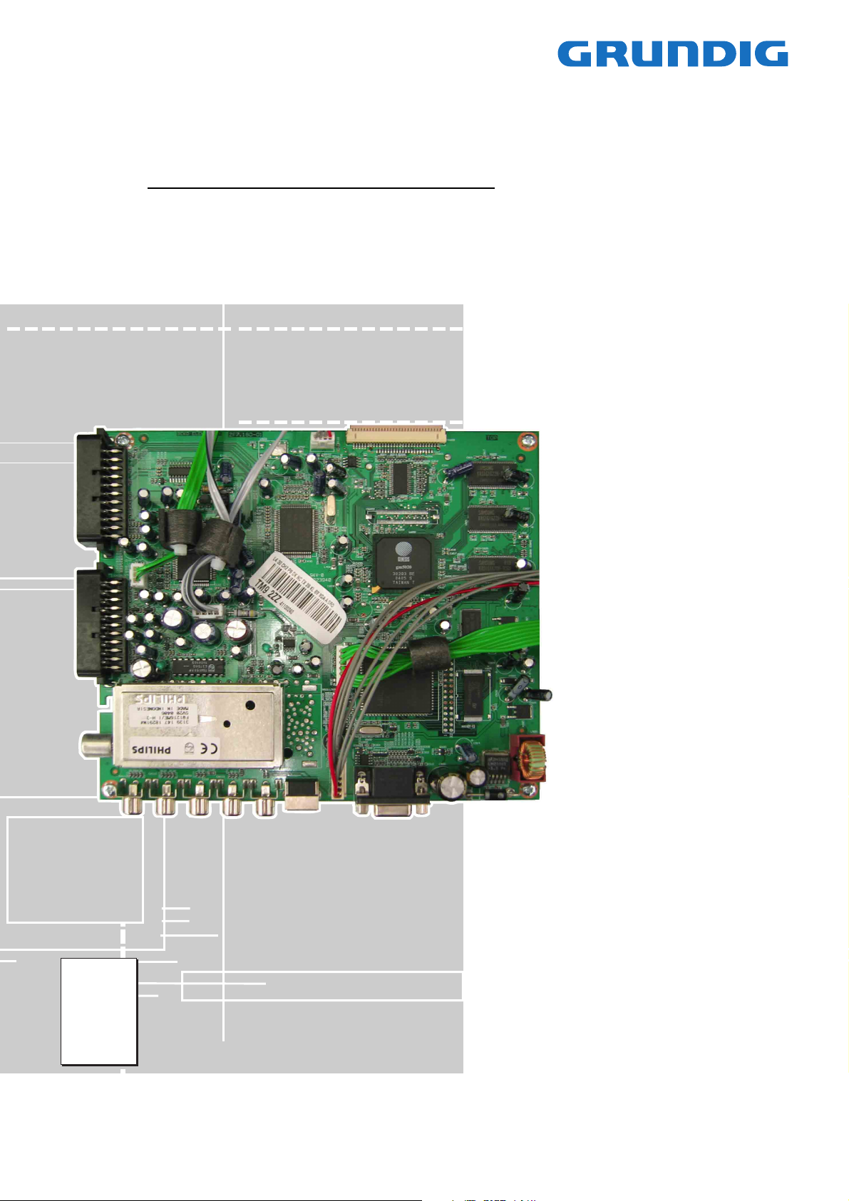
CTV Service Manual
Chassis L4
Davio 30 LW 76-4501 TOP
GBD9300
Zusätzlich erforderliche Unterlagen für den Komplettservice
Additionally required Service Documents for the Complete Service
Service
Manual
Sicherheit
Safety
Materialnr./Part No.
720108000001
Materialnummer/Part Number 720100495000
Änderungen vorbehalten/Subject to alteration
H-S41 1105
http://www.grundig.com
GRUNDIG Service Chassis L4
Es gelten die Vorschriften und Sicherheitshinweise
gemäß dem Service Manual "Sicherheit", Materialnummer 720108000001, sowie zusätzlich die eventuell abweichenden, landesspezifischen Vorschriften!
Inhaltsverzeichnis
Seite
Allgemeiner Teil ................................... 1-2…1-8
Allgemeine Hinweise .................................................................... 1-2
Technische Daten ........................................................................ 1-3
Bedienhinweise ............................................................................ 1-4
Service- und Sonderfunktionen .................................................... 1-7
Platinenabbildungen
und Schaltpläne ................................. 2-1…2-15
Verdrahtungsplan ......................................................................... 2-1
Blockschaltplan ............................................................................ 2-1
Hauptplatte ................................................................................... 2-2
– Netzteil ..................................................................................... 2-6
– SVGA-Eingang......................................................................... 2-6
– IN/OUT ..................................................................................... 2-7
– Video-Konverter ....................................................................... 2-8
– Prozessor ................................................................................. 2-9
– Scaler ..................................................................................... 2-10
– Speicher ................................................................................. 2-11
– Display-Treiber....................................................................... 2-12
Bedieneinheit ............................................................................. 2-13
Kopfhörer-Platte ......................................................................... 2-13
Oszillogramme ........................................................................... 2-14
The regulations and safety instructions shall be valid
as provided by the "Safety" Service Manual, part
number 720108000001, as well as the respective
national deviations.
Table of Contents
Page
General Section .................................... 1-2…1-8
General Notes .............................................................................. 1-2
Technical Data ............................................................................. 1-3
Operating Hints ............................................................................ 1-5
Service and Special Functions ..................................................... 1-7
Layout of PCBs
and Circuit Diagrams ......................... 2-1…2-15
Wiring Diagram ............................................................................ 2-1
Block Circuit Diagram .................................................................. 2-1
Main Board ................................................................................... 2-2
– Power Supply ........................................................................... 2-6
– SVGA Input .............................................................................. 2-6
– IN/OUT ..................................................................................... 2-7
– Video Converter ....................................................................... 2-8
– Processor ................................................................................. 2-9
– Scaler ..................................................................................... 2-10
– Memory .................................................................................. 2-11
– Display Driver ......................................................................... 2-12
Keyboard .................................................................................... 2-13
Headphone Board ...................................................................... 2-13
Oscillograms .............................................................................. 2-14
Ersatzteillisten ...................................... 3-1…3-3
Allgemeiner Teil
Allgemeine Hinweise
Vor dem Öffnen des Gehäuses den Netzstecker ziehen!
Achtung: ESD-Vorschriften beachten
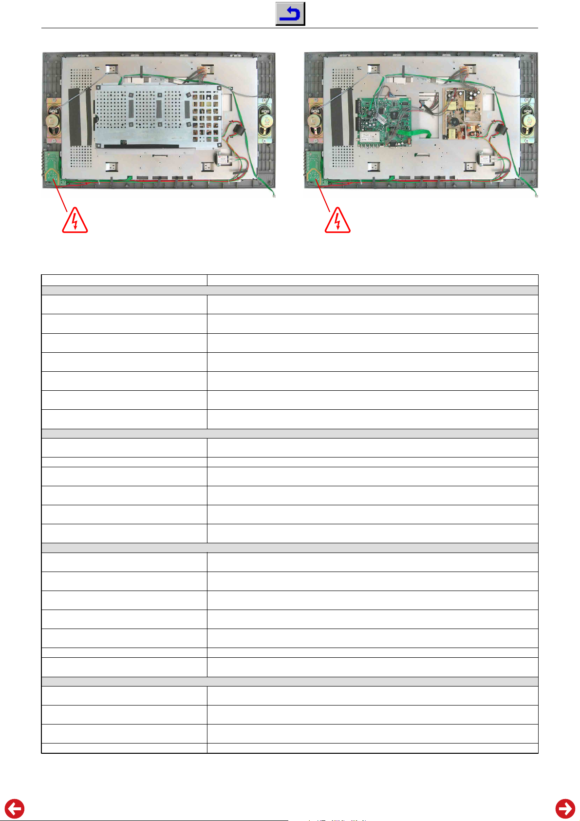
Leitungsverlegung
Bevor Sie die Leitungen und insbesondere die Masseleitungen lösen,
muss die Leitungsverlegung zu den einzelnen Baugruppen beachtet
werden.
Nach erfolgter Reparatur ist es notwendig, die Leitungsführung wieder
in den werkseitigen Zustand zu versetzen um evtl. spätere Ausfälle
oder Störungen zu vermeiden.
Durchführen von Messungen
Bei Messungen mit dem Oszilloskop an Halbleitern sollten Sie nur
Tastköpfe mit 10:1 - Teiler verwenden. Außerdem ist zu beachten,
dass nach vorheriger Messung mit AC-Kopplung der Koppelkondensator des Oszilloskops aufgeladen sein kann. Durch die Entladung
über das Messobjekt können Bauteile beschädigt werden.
Messwerte und Oszillogramme
Bei den in den Schaltplänen und Oszillogrammen angegebenen
Messwerten handelt es sich um Näherungswerte!
Spare Parts Lists .................................. 3-1…3-3
General Section
General Notes
Before opening the cabinet disconnect the mains plug!
Attention: Observe the ESD safety regulations
Wiring
Before disconnecting any leads and especially the earth connecting
leads observe the way they are routed to the individual assemblies.
On completion of the repairs the leads must be laid out as originally
fitted at the factory to avoid later failures or disturbances.
Carrying out Measurements
When making measurements on semi-conductors with an oscilloscope, ensure that the test probe is set to 10:1 dividing factor. If the
previous measurement was made on AC input, please note that the
coupling capacitor in the oscilloscope will be charged. Discharge via
the item being checked can damage the components.
Measured Values and Oscillograms
The measured values given in the circuit diagrams and oscillograms
are approximates!
1 - 2
Technische Daten / Technical Data
Chassis L4GRUNDIG Service
TFT LCD Panel
Sichtbares Bild
Visible picture
Bildschirmdiagonale
Screen diagonal
Maximale Auflösung
Resolution max.
Kontrastverhältnis
Contrast ratio
Leuchtdichte
Brightness
Betrachtungswinkel
Viewing angel
Display-Trägheit
Response time
Elektronik / Electronic
Programmspeicherplätze
Programme positions
Tuner
TV-Normen
TV-Standards
Stereo Systeme
Stereo systems
Videotext
Teletext
Musikleistung
Music power
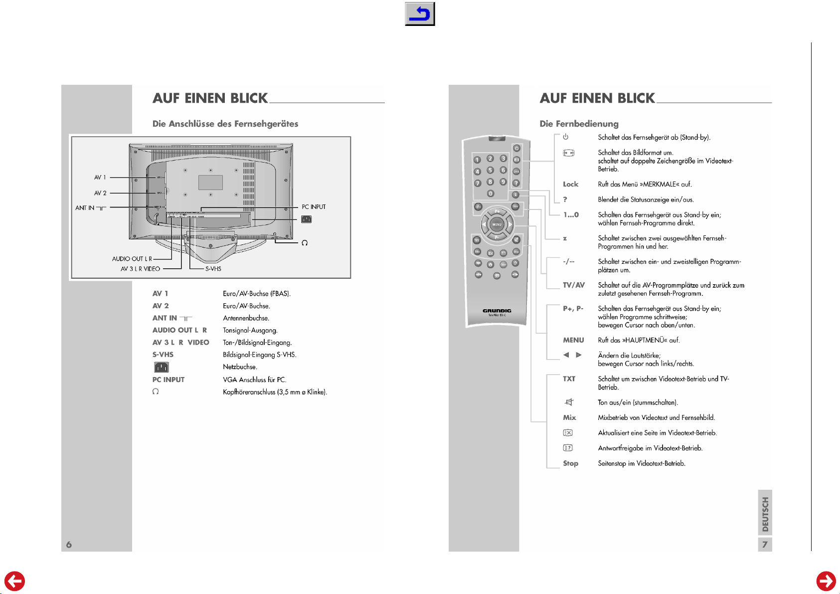
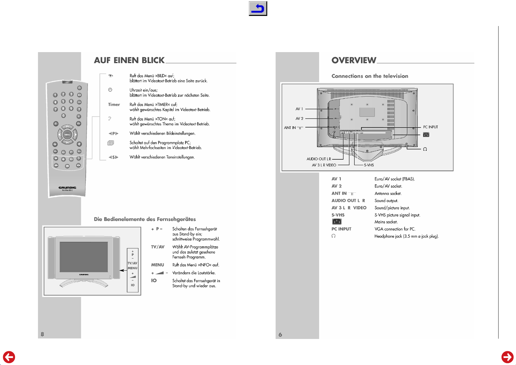
Anschlüsse Rückwand / Connections Rear Panel
Euro AV 1
Euro AV 2
Cinch-AV-Buchse Eingang
Cinch-AV socket input
S-Videoeingangsbuchse
S-Video input socket
LINE-Buchse Ausgang
LINE socket output
VGA
Kopfhörerbuchse
Headphone jack
Netzteil / Mains Stage
Netzspannung (Regelbereich)
Mains voltage (variable)
Netzfrequenz
Mains frequency
Leistungsaufnahme
Power consumption
Standby
Davio 30 LCD 76-4501 TOP
(J6F)
76cm
76cm (30")
1280 x 768 Pixel
600:1
550cd/m
2
170° horizontal, 170° vertikal
170° horizontal, 170° vertical
25ms (typ.)
99 + 5AV
1 terr. PLL Frequenz Synthesizer Tuning, global Pinning
PAL, SECAM, über/via AV NTSC 3.58/4.43MHz,
B/G, L/L', I, D/K/K'
German A2 (B/G/D/K/I)
Nicam 5.85MHz (BG, L) + 6.52MHz (I)
124-Seiten / pages
2 x 7W (2 x 5W Sinus)
FBAS Ein-/Ausgang, RGB Eingang, SBAS Eingang, Audio Ein-/Ausgang
CCVS in-/output, RGB input, SCVS input, Audio in-/output
FBAS Ein-/Ausgang, Audio Ein-/Ausgang
CCVS in-/output, Audio in-/output
FBAS Eingang, 2x Audio Stereoeingang
CCVS input, 2x audio stereo input
4-polige Hosidenbuchse
4-pin mini-Din
2x Audio (Stereo)
2x audio (stereo)
Bildschirmauflösung / Screen resolution 1280 x 768 Pixel
Stereoklinkenbuchse mit Lautsprecher Abschaltung (3,5mm)
Stereo minijack with speaker cut off (3.5mm)
220-240V AC
50 / 60Hz
ca. 180W
ca. 3W
1 - 3
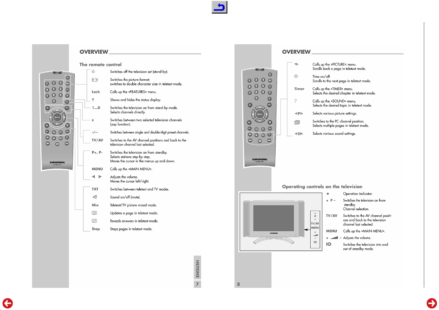
Bedienhinweise Dieses Kapitel enthält Auszüge aus der Bedienungsanleitung.
Weitergehende Informationen entnehmen Sie bitte der gerätespezifischen Bedienungsanleitung, deren Materialnummer Sie in der entsprechenden Ersatzteilliste finden.
1 - 4
Chassis L4GRUNDIG Service
1 - 5
Operating Hints This chapter contains excerpts from the operating instructions.
For further particulars please refer to the appropriate user instructions the
part number of which is indicated in the relevant spare parts list.
Chassis L4GRUNDIG Service
1 - 6
Chassis L4GRUNDIG Service
Chassis L4GRUNDIG Service
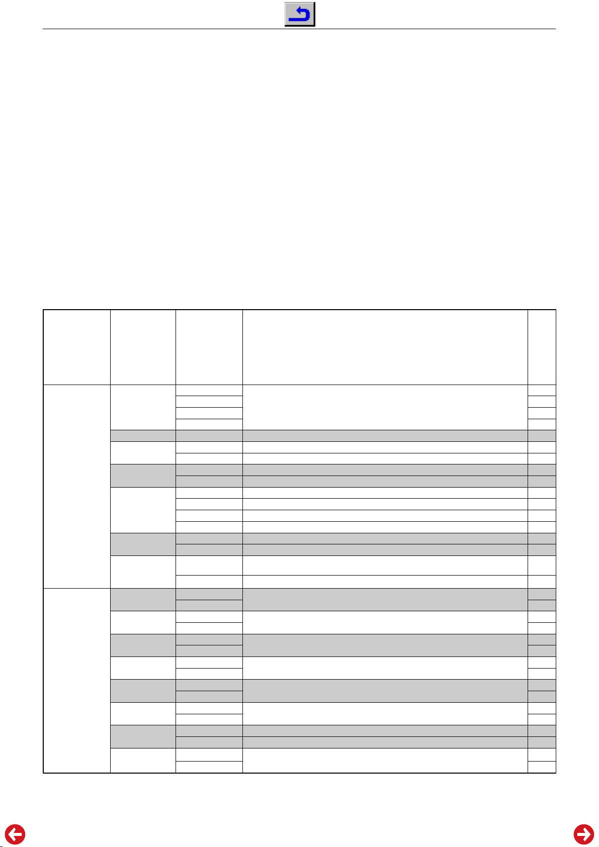
Service- und Sonderfunktionen
Tastenfunktionen
MENU
"
rot
" Service Menü 1
"
blau
" Service Menü 2
"
grün
" Service Menü 3
P+/P–
ǸǸ
ǸǸ
/ Ƿ Wert ändern
TXT
Service-Mode aktivieren
– Tas t e "
– Zahlenfolge "8500" eingeben. Auf dem Bildschirm wird das
Service Menü 1 angezeigt.
– Service Menüs 1 bis 3 mit den Tasten "
fen.
Service-Mode beenden
– Tas t e "
Die Software-Versionsnummer wird kurzzeitig angezeigt.
1. Grundeinstellwerte
Die Grundeinstellwerte im Service Mode sind in der Tabelle enthalten.
Service Menü
Service Menu
Aufrufen des Dialog Centers
Menü-Zeile (Menüpunkt) wählen
Beenden des Service Mode
MENU
" (Hauptmenü) drücken.
TXT
" drücken.
Menüpunkt
Point of Menu
P+ / P–
TUNER
"
blue
" / button "
blau
Taste "
AGC
STANDBY
SWAP/ZAPP
TEXT
SECAM AUD
LANGUAGE
BG
DK
I
L
NICAM
HEADPHONE
CARR.MUTE
MONITOR
"
red
" / button "
rot
Taste "
Service Menü 1 / Service Menu 1
Menü 2 / Menu 2
rot
", "
blau
" oder "
Einstellung
Adjustment
Ǹ / Ƿ
PHILIPS-ME
PHILIPS-MEPT
SAMSUNG-28A
SAMSUNG-27D
0…7
YES
NO
SWAP
ZAPP
DEFAULT
FASTEXT
TOPTEXT
TOP&FAST
BY TUNER
BY MSP
GROUP0
GROUP1
YES
NO
YES
NO
YES
NO
YES
NO
YES
NO
YES
NO
BY MSP
BY MICRO
YES
NO
grün
" aufru-
eingebautes Display wählen
select used display
Netz-Ein –> Standby / Power on –> standby
Netz-Ein –> Programm 1 / Power on – programme 1
Fast-Text
TOP-Text
TOP & Fast-Text x
English, German, French, Italian, Spanish, Portuguese, Turkish, Svenska, Norwegian, Danish, Dutch, Suomi, Polish, Greek, Russian, Hebrew
TV-Norm BG
TV-Norm DK – nur bei Ost-Europa / only for east europe "YES"
TV-Norm I
TV-Norm L – nur bei West-Europa / only for west europe "YES"
NICAM-Ton / Sound
Kopfhörer vorhanden / Headphone available
VGA-Buchse vorhanden / VGA socket available
Service and Special Functions
Functions of the buttons
MENU
"
red
" Call up the Service Menu 1
"
blue
" Call up the Service Menu 2
"
green
" Call up the Service Menu 3
P+/P–
ǸǸ
ǸǸ
/ Ƿ Changing the settings in the Service Menu
TXT
Calling up the Service Mode
– Press button "
– Enter the code number "8500". The Service Menu 1 is shown on
the screen.
– Call up the Service Menu 1 to 3 with the buttons "
"
green
Exit the Service Mode
– Press button "
The software version number is shown.
1. Basic Settings
The table shows all basic specific settings in the service mode.
Call up the Dialog Center
Call up te dialogue line (point of menu)
Exit the Service Mode
MENU
" (Main Menu).
".
TXT
".
Hinweis
Hint
red
", "
blue
" or
Davio 30
3
x
x
x
x
x
x
x
x
x
x
x
x
LW 76-4501 TOP
1 - 7
Chassis L4GRUNDIG Service
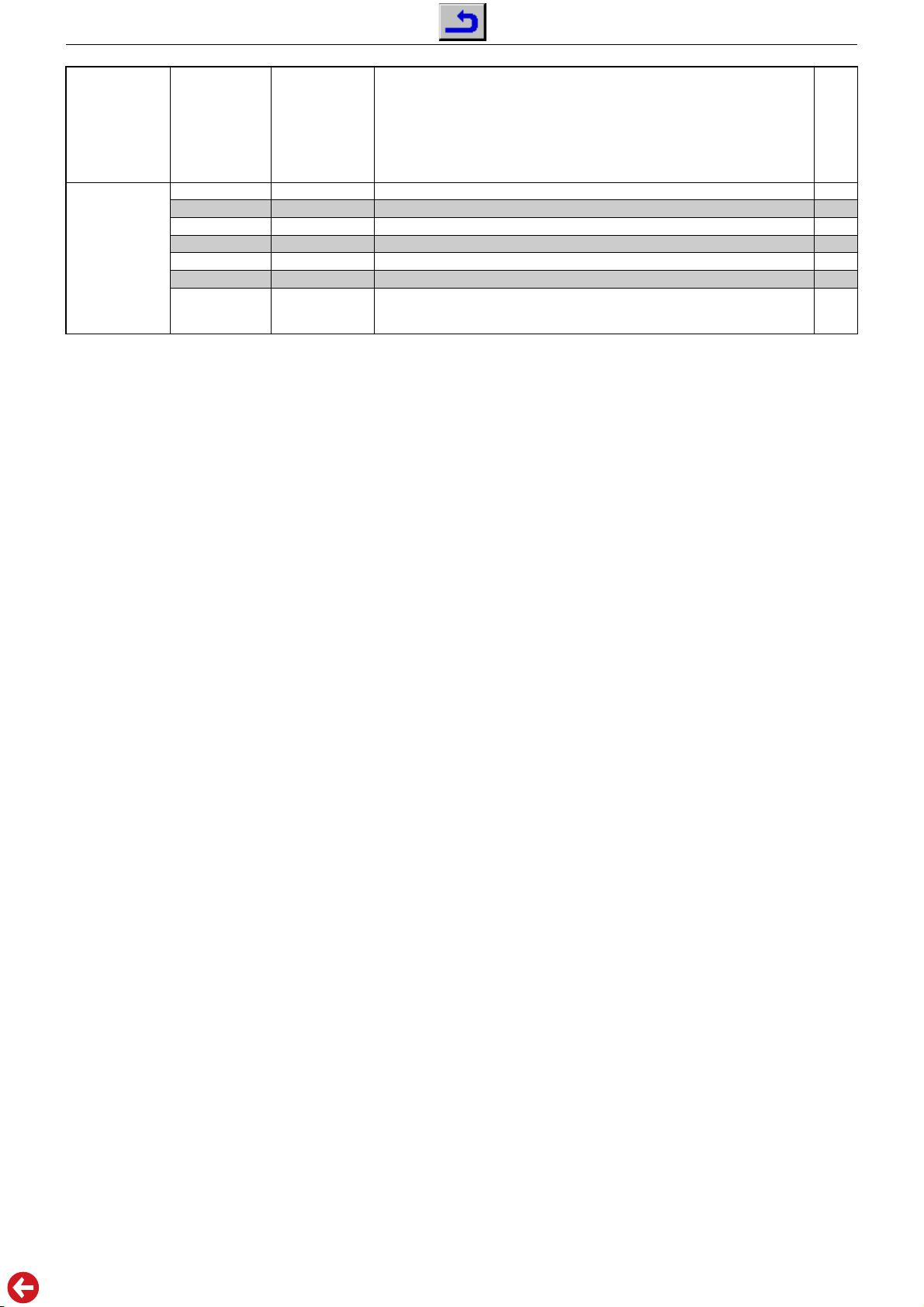
Service Menü
Service Menu
"
"
grün
green
Taste "
button "
Service Menü / Menu 3
* Wert gegebenenfalls so verändern, dass die dunklen Bildberei-
che eines Grautreppentestbildes unbunt sind.
** Wert gegebenenfalls so verändern, dass die hellen Bildbereiche
eines Grautreppentestbildes unbunt sind.
2. Austausch der Hauptplatte oder des U506
Nach dem Austausch der Hauptplatte oder des U506 sind alle Einstellungen im Service Mode entsprechend der Tabelle "Grundeinstellwerte" (Punkt 1) durchzuführen.
3. Software-Versionsnummer
Die Software-Versionsnummer wird nach dem Beenden des Service Modes angezeigt, z.B.:
Menüpunkt
Point of Menu
P+ / P–
R. CUT
G. CUT
B. CUT
R. DRV
G. DRV
B. DRV
BACKLIGHT
SL430WGC04
TEST:03 20/08/04
Einstellung
Adjustment
Ǹ / Ƿ
0…255
0…255
0…255
0…255
0…255
0…255
0…4
Cut off-Wert "rot" / Cut off value "red" 1*
Cut off-Wert "grün" / Cut off value "green"
Cut off-Wert "blau" / Cut off value "blue"
Weißabgleich "rot" / White balance "red"
Weißabgleich "grün" / White balance "green"
Weißabgleich "blau" / White balance "blue"
Hintergrundbeleuchtung / Backlight:
0 = hell / bright
4 = dunkel / dark
Hinweis
Hint
Davio 30
LW 76-4501 TOP
3*
0*
0**
0**
5**
0
* If nesessary change the settings so that the dark part of the
greyscale test pattern is achromatic.
** If nesessary change the settings so that the bright part of the
greyscale test pattern is achromatic.
2. Change of Main Board or U506
After changing the Main Board or U506 all settings in the service
mode must be done according to the table "Basic Settings"
(point 1).
3. Software Version Number
The software version number is shown after ending the service
mode, e.g.:
SL430WGC04
TEST:03 20/08/04
3. Programmsuchlauf
– Taste "
– "SUCHLAUF / ABSTIMMUNG" mit den Tasten
– "PROGRAMMSUCHLAUF" mit den Tasten
– Land mit den Tasten
Zum Abbrechen des Suchlaufes die Taste "
MENU
" (Hauptmenü) drücken.
und mit der Taste "
mit der Taste "
MENU
" bestätigen.
"
Das automatische Sendersuchsystem stoppt bei jedem empfangswürdigen Sender (AFC und Koinzidenz) und speichert automatisch die entsprechenden Senderdaten mit dem jeweiligen
Standard. Danach wird der Suchlauf fortgesetzt.
MENU
MENU
" bestätigen.
" bestätigen.
P+ / P–
, Ǹ / Ƿ auswählen und mit der Taste
P+ / P–
MENU
P+ / P–
anwählen und
" drücken.
anwählen
3. Programme Search
– Press button "
– Select "SETUP" with the buttons
"
MENU
– Select "AUTOPROGRAM" with the buttons
with button "
– Select the Country with the buttons
with button "
The autoprogram system stops at every station of acceptable reception quality (AFC and coincidence) and stores the station data
and the respective standard automatically. The system then continues searching.
Pressing the "
MENU
" (Main Menu).
".
MENU
".
MENU
".
MENU
" button stops the programme search.
P+ / P–
and confirm with button
P+
/
P+ / P–
, Ǹ / Ƿ and confirm
P–
and confirm
1 - 8
 Loading...